EP4068216A1 - 3d digital model surface rendering and conversion - Google Patents
3d digital model surface rendering and conversion Download PDFInfo
- Publication number
- EP4068216A1 EP4068216A1 EP22159068.0A EP22159068A EP4068216A1 EP 4068216 A1 EP4068216 A1 EP 4068216A1 EP 22159068 A EP22159068 A EP 22159068A EP 4068216 A1 EP4068216 A1 EP 4068216A1
- Authority
- EP
- European Patent Office
- Prior art keywords
- digital model
- action
- color values
- coordinate space
- lighting color
- Prior art date
- Legal status (The legal status is an assumption and is not a legal conclusion. Google has not performed a legal analysis and makes no representation as to the accuracy of the status listed.)
- Granted
Links
Images




Classifications
-
- G—PHYSICS
- G06—COMPUTING OR CALCULATING; COUNTING
- G06T—IMAGE DATA PROCESSING OR GENERATION, IN GENERAL
- G06T15/00—Three-dimensional [3D] image rendering
- G06T15/10—Geometric effects
- G06T15/20—Perspective computation
-
- G—PHYSICS
- G06—COMPUTING OR CALCULATING; COUNTING
- G06T—IMAGE DATA PROCESSING OR GENERATION, IN GENERAL
- G06T15/00—Three-dimensional [3D] image rendering
- G06T15/10—Geometric effects
- G06T15/20—Perspective computation
- G06T15/205—Image-based rendering
-
- G—PHYSICS
- G06—COMPUTING OR CALCULATING; COUNTING
- G06T—IMAGE DATA PROCESSING OR GENERATION, IN GENERAL
- G06T15/00—Three-dimensional [3D] image rendering
- G06T15/04—Texture mapping
-
- G—PHYSICS
- G06—COMPUTING OR CALCULATING; COUNTING
- G06T—IMAGE DATA PROCESSING OR GENERATION, IN GENERAL
- G06T15/00—Three-dimensional [3D] image rendering
- G06T15/50—Lighting effects
-
- G—PHYSICS
- G06—COMPUTING OR CALCULATING; COUNTING
- G06T—IMAGE DATA PROCESSING OR GENERATION, IN GENERAL
- G06T15/00—Three-dimensional [3D] image rendering
- G06T15/50—Lighting effects
- G06T15/506—Illumination models
-
- G—PHYSICS
- G06—COMPUTING OR CALCULATING; COUNTING
- G06T—IMAGE DATA PROCESSING OR GENERATION, IN GENERAL
- G06T17/00—Three-dimensional [3D] modelling for computer graphics
- G06T17/20—Finite element generation, e.g. wire-frame surface description, tesselation
-
- G—PHYSICS
- G06—COMPUTING OR CALCULATING; COUNTING
- G06T—IMAGE DATA PROCESSING OR GENERATION, IN GENERAL
- G06T19/00—Manipulating three-dimensional [3D] models or images for computer graphics
-
- H—ELECTRICITY
- H04—ELECTRIC COMMUNICATION TECHNIQUE
- H04N—PICTORIAL COMMUNICATION, e.g. TELEVISION
- H04N13/00—Stereoscopic video systems; Multi-view video systems; Details thereof
- H04N13/20—Image signal generators
- H04N13/275—Image signal generators from three-dimensional [3D] object models, e.g. computer-generated stereoscopic image signals
-
- H—ELECTRICITY
- H04—ELECTRIC COMMUNICATION TECHNIQUE
- H04N—PICTORIAL COMMUNICATION, e.g. TELEVISION
- H04N13/00—Stereoscopic video systems; Multi-view video systems; Details thereof
- H04N13/20—Image signal generators
- H04N13/282—Image signal generators for generating image signals corresponding to three or more geometrical viewpoints, e.g. multi-view systems
Definitions
- the present invention provides a method and a system according to the independent claims to better comply with this need.
- the present application discloses systems and methods for performing three-dimensional (3D) digital model surface rendering and conversion that overcome the drawbacks and deficiencies in the conventional art.
- the solution disclosed in the present application enables the automated conversion of a large portion of the information that captures the appearance of a high complexity rendered 3D digital model to a flexible, pipeline agnostic format that that allows the converted model to be interoperable among different pipelines and studios.
- the expression "high complexity,” when used to describe a digital object, such as a 3D digital model for example refers to a digital object of such extensive detail that it cannot be rendered fast enough for use in real-time applications.
- pipeline agnostic when used to describe a feature, refers to a feature that is not limited to use with a specific pipeline architecture, but may be used and processed in several or substantially all of the different pipelines utilized by various studios.
- the pipeline agnostic format is easily scalable so that the data describing the converted model can be represented at the full original resolution or a reduced representation that compresses the large set of data available from the original high complexity 3D digital model.
- the present solution advantageously captures and converts lighting information of the scene as well as non-lighting specific information such as normal, ambient occlusion, and the original UV texture coordinates of the 3D digital model.
- the present solution improves on present state-of-the-art light baking techniques by capturing many layers of information about the rendered 3D digital model beyond merely lighting contributions.
- the terms “automation,” “automated,” and “automating” refer to systems and processes that do not require human intervention.
- a human artist or editor may review or even modify a surface projection of a 3D digital object produced by the systems described herein, that human involvement is optional.
- the methods for performing 3D digital model surface rendering and conversion described in the present application may be performed under the control of hardware processing components executing them.
- FIG. 1 shows a diagram of an exemplary image processing system for performing 3D digital model surface rendering and conversion, according to one implementation.
- image processing system 100 includes computing platform 102 having processing hardware 104, display 112, and system memory 106 implemented as a computer-readable non-transitory storage medium.
- image processing system 100 may exist in a use environment including communication network 114, workstation terminal 130 including display 132, and artist or user 118 (hereinafter "user 118") utilizing workstation terminal 130.
- FIG. 1 Also shown in Figure 1 are 3D digital model 134, software code 110, and surface projection 146 of 3D digital model 134 (hereinafter “surface projection 146") produced by software code 110, as well as network communication links 116 interactively connecting workstation terminal 130 and image processing system 100 via communication network 114.
- surface projection 146 3D digital model 134
- network communication links 116 interactively connecting workstation terminal 130 and image processing system 100 via communication network 114.
- system memory 106 may take the form of any computer-readable non-transitory storage medium.
- computer-readable non-transitory storage medium refers to any medium, excluding a carrier wave or other transitory signal that provides instructions to a hardware processor of a computing platform, such as processing hardware 104 of computing platform 102.
- a computer-readable non-transitory storage medium may correspond to various types of media, such as volatile media and non-volatile media, for example.
- Volatile media may include dynamic memory, such as dynamic random access memory (dynamic RAM), while non-volatile memory may include optical, magnetic, or electrostatic storage devices.
- Common forms of computer-readable non-transitory storage media include, for example, optical discs, RAM, programmable read-only memory (PROM), erasable PROM (EPROM), and FLASH memory.
- Figure 1 depicts software code 110 and surface projection 146 as being located together in system memory 106 that representation is also merely provided as an aid to conceptual clarity.
- image processing system 100 may include one or more computing platforms, such as computer servers for example, which may be co-located, or may form an interactively linked but distributed system, such as a cloud-based system, for instance.
- processing hardware 104 and system memory 106 may correspond to distributed processor and memory resources within image processing system 100.
- software code 110 and surface projection 146 may be stored remotely from one another within the distributed memory resources of image processing system 100.
- Figure 1 depicts surface projection 146 as residing in system memory 106, in some implementations, surface projection 146 may be copied to non-volatile storage.
- Processing hardware 104 may include multiple hardware processing units, such as one or more central processing units, one or more graphics processing units, and one or more tensor processing units.
- CPU central processing unit
- GPU graphics processing unit
- TPU tensor processing unit
- a CPU includes an Arithmetic Logic Unit (ALU) for carrying out the arithmetic and logical operations of computing platform 102, as well as a Control Unit (CU) for retrieving programs, such as software code 110, from system memory 106, while a GPU may be implemented to reduce the processing overhead of the CPU by performing computationally intensive graphics or other processing tasks.
- a TPU is an application-specific integrated circuit (ASIC) configured specifically for artificial intelligence (AI) processes such as machine learning.
- ASIC application-specific integrated circuit
- computing platform 102 may correspond to one or more web servers, accessible over a packet-switched network such as the Internet, for example.
- computing platform 102 may correspond to one or more computer servers supporting a private wide area network (WAN), local area network (LAN), or included in another type of limited distribution or private network.
- communication network 114 may be a high-speed network suitable for high performance computing (HPC), for example a 10 GigE network or an Infiniband network.
- HPC high performance computing
- workstation terminal 130 is shown as a desktop computer in Figure 1 , that representation is provided merely as an example as well. More generally, workstation terminal 130 may be any suitable mobile or stationary computing device or system that includes display 132 and implements data processing capabilities sufficient to implement the functionality ascribed to workstation terminal 130 herein.
- workstation terminal 130 may take the form of a laptop computer, tablet computer, or smartphone, for example.
- workstation terminal 130 may be a dumb terminal existing as a peripheral feature of image processing system 100.
- display 132 of workstation terminal 130 may be controlled by processing hardware 104 and software code 110 of computing platform 102.
- displays 112 and 132 may be implemented as liquid crystal displays (LCDs), light-emitting diode (LED) displays, organic light-emitting diode (OLED) displays, quantum dot (QD) displays, or any other suitable display screens that perform a physical transformation of signals to light.
- display 132 may be physically integrated with workstation terminal 130 or may be communicatively coupled to but physically separate from workstation terminal 130.
- display 132 may take the form of a monitor separate from workstation terminal 130 in the form of a computer tower.
- Figure 2A shows flowchart 200 presenting an exemplary method for performing 3D digital model surface rendering and conversion, according to one implementation, while Figures 3 and 4 depict exemplary intermediate actions included in flowchart 200, and Figure 5 shows an exemplary surface projection of a 3D digital model, according to one implementation.
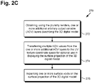
- Figure 2B shows a flowchart outlining action 260 in flowchart 200 in greater detail, according to one implementation, while Figure 2C shows a flowchart outlining action 270 in greater detail, according to one implementation.
- the present method relies solely on rendered images of 3D digital model 134.
- the present method works by generating a set of virtual cameras surrounding 3D digital model 134.
- Each of the virtual cameras is then rendered and projected back onto a 3D mesh representing 3D digital model 134, resulting in surface projection 146.
- surface projection 146 By projecting the renders in this way, all of the information stored in the renders can be captured on surface projection 146 of 3D digital model 134.
- VFX studio visual effects
- 3D digital model 134 may be a high complexity 3D model of a human being, character, animal, inanimate object, or may depict a scene including multiple digital objects.
- 3D digital model 134 may be represented by a mesh having a mesh element count in the millions, or tens of millions.
- 3D digital model 134 may be a VFX digital asset created for use in a feature film.
- the feature "mesh element count” refers to the number of individual surface components included in a surface conforming mesh representation.
- the mesh element count of a triangle mesh is its triangle count
- the mesh element count of a more generalized polygon mesh is its polygon count.
- 3D digital model 134 may be received from user 118 via workstation terminal 130, communication network 114, and network communication links 116.
- 3D digital model 134 may be stored in system memory 106 and may be received in action 210 as a data transfer within system memory 106.
- 3D digital model 134 may be received in action 210 by software code 110, executed by processing hardware 104 of computing platform 102.
- Flowchart 200 further includes surrounding 3D digital model 134 with multiple virtual cameras oriented toward 3D digital model 134 (action 220).
- 3D digital model 134 may be a high complexity 3D model of a human being, character, animal, or inanimate object.
- 3D digital model 334 may take the form of a 3D sculpted bust. It is noted that 3D digital model 334 corresponds in general to 3D digital model 134, in Figure 1 , and those corresponding features may share any of the characteristics attributed to either feature by the present disclosure.
- 3D digital model 334 may be represented by a mesh having a mesh element count in the millions, or tens of millions.
- 3D digital model 334 may be a film quality VFX digital asset.
- action 220 may include generating a two-dimensional (2D) closed surface, such as a sphere for example, surrounding 3D digital model 134/334, and situating multiple virtual cameras corresponding to exemplary virtual cameras 340a and 340b on that 2D closed surface.
- virtual cameras 340a and 340b may be placed on any one or more 2D closed surfaces surrounding 3D digital model 134/334 and having shapes that are not limited to spheres.
- An exemplary technique for surrounding 3D digital model 134 with multiple virtual cameras is described in U.S. Patent Application Serial No. 17/211,724, filed on March 24, 2021 , and titled "Volumetric Representation of Digital Objects from Depth Renderings," which is hereby incorporated fully by reference into the present application.
- action 220 includes surrounding 3D digital model 134/334 by a sufficient number of virtual cameras having locations such that substantially all external feature of 3D digital model 134/334 can be captured by at least one of the virtual cameras, i.e., substantially the entire external surface of 3D digital model 134/334 may be viewed or mapped by the multiple virtual cameras surrounding 3D digital model 134/334.
- Figure 3 explicitly identifies two virtual cameras 340a and 340b, more generally virtual cameras 340a and 340b may correspond to tens or hundreds of virtual cameras each located so as to have a unique perspective of 3D digital model 134/334.
- virtual cameras 340a and 340b may be implemented using a variety of different camera configurations and lens parameters, such as different focal lengths.
- virtual cameras 340a and 340b may take the form of panoramic cameras.
- Action 220 may be performed by software code 110, executed by processing hardware 104 of computing platform 102.
- flowchart 200 may further include determining a best virtual camera among virtual cameras 340a and 340b for rendering each of multiple surface portions of 3D digital model 134/334 (action 230).
- Figure 4 shows virtual camera 440a having perspective 442a of 3D digital model 434 and virtual camera 440b having another perspective 442b of 3D digital model 434.
- 3D digital model 434 corresponds in general to 3D digital model 134/334, in Figures 1 and 3 .
- 3D digital model 434 may share any of the characteristics attributed to 3D digital model 134/334 by the present disclosure, and vice versa.
- virtual cameras 440a and 440b, in Figure 4 correspond respectively in general to virtual cameras 340a and 340b, in Figure 3 , and those corresponding features may share any of the characteristics attributed to either corresponding feature by the present disclosure.
- virtual cameras 440a and 440b may correspond to tens or hundreds of virtual cameras each located so as to have a unique perspective of 3D digital model 134/334/434.
- 3D digital model 134/334/434 may be viewed by more than one of virtual cameras 340a/440a and 340b/440b.
- a determination of the "best" virtual camera to use in rendering each surface portion of 3D digital model 134/334/434 may be made.
- a metric to make such a determination based on one or both of two factors: 1) the pixel density on a particular surface portion from the perspective of a given virtual camera, and 2) a measure of how perpendicular the camera lens is to a normal vector of that surface portion. That is to say, the respective best virtual camera for rendering each surface portion of 3D digital model 134/334/434 may be determined based on at least one of a pixel density of each of the surface portions from the perspective of the respective best virtual camera or a lens orientation of the respective best virtual camera relative to an axis perpendicular to each of the surface portions. In some implementations, for example, the determination may be made using a weighted combination of these two factors.
- Action 230 may be performed by software code 110, executed by processing hardware 104 of computing platform 102.
- Flowchart 200 further includes generating, using each of virtual cameras 340a/440a and 340b/440b, a respective render of 3D digital model 134/334/434, resulting in multiple renders of 3D digital model 134/334/434 (action 240).
- generating the multiple renders of 3D digital model 134/334/434 in action 240 may include rendering each surface portion using the respective best virtual camera determined for that surface portion.
- action 240 results in substantially all surface portions of 3D digital model 134/334/434 being included in at least one of the multiple renders of 3D digital model 134/334/434.
- Action 240 may be performed by software code 110, executed by processing hardware 104 of computing platform 102. It is noted that, in some implementations, action 240 may follow directly from action 220, while action 230 may be omitted. However, in other implementations, action 240 may follow action 230, which may follow action 220, as shown in Figure 2A .
- Flowchart 200 further includes generating a UV texture coordinate space for surface projection 146 of 3D digital model 134/334/434 (action 250).
- a UV texture coordinate space may be utilized to store a 2D image that is mapped to a 3D surface shape.
- Such a UV texture coordinate space can be generated using traditional texture coordinate seaming and packing algorithms known in the art. It is noted that, in some implementations, multiple UV texture coordinate spaces can be generated to increase the pixel density of surface projection 146, as desired. By using renders from virtual cameras that are positioned closer or further away from 3D digital model 134/334/434, the final resolution of surface projection 146 can be adjusted to be higher or lower accordingly.
- Action 250 may be performed by software code 110, executed by processing hardware 104 of computing platform 102.
- Flowchart 200 further includes transferring, using the multiple renders generated in action 240, lighting color values for each of the multiple surface portions of 3D digital model 134/334/434 to the UV texture coordinate space generated in action 250 (action 260).
- action 260 which may include actions 262, 264, 266, and 268, may be performed by software code 110, executed by processing hardware 104 of computing platform 102.
- action 260 may include sampling, using the multiple renders, red-green-blue (RGB) color values corresponding respectively to each of the multiple surface portions of 3D digital model 134/334/434 (action 262).
- Action 260 may further include omitting view dependent lighting color values corresponding to light that is one or both of reflected or refracted from one or more of the surface portions of 3D digital model 134/334/434 from the RGB color values sampled in action 262, to produce the lighting color values for transferring to the UV texture coordinate space (action 264).
- the lighting color values transferred to the UV texture coordinate space in action 260 may be view independent lighting color values. It is noted that without the omission of view dependent lighting color values in action 264 there would typically be undesirable visible seams in surface projection 146 as the lighting color changes depending on the respective locations of virtual cameras 340a/440 and 340b/440b.
- action 260 may include transferring the view independent lighting color values produced in action 264 to the UV texture coordinate space generated in action 250 as a beauty lighting layer that stores the final fully lit pixel rendering of surface projection 146 (action 266). Moreover, in some implementations, action 260 may further include transferring the omitted view dependent lighting color values to the UV texture coordinate space as a view dependent lighting layer of surface projection 146 (action 268). It is noted that, in some implementations, action 260 may conclude with action 266 and action 268 may be omitted. Moreover, in some implementations in which action 268 is performed, action 266 and 268 may be performed in parallel, i.e., substantially concurrently.
- flowchart 200 may conclude with action 260 described above. However, in other implementations, flowchart 200 may continue and conclude with executing one or more additional image processing techniques to enhance surface projection 146 of 3D digital model 134/334/434 (action 270).
- action 270 may include actions 272, 274, and 276, may be performed by software code 110, executed by processing hardware 104 of computing platform 102.
- action 270 may include obtaining, using the renders generated in action 240, one or more additional output AOV layers describing 3D digital model 134/334/434 action (372), and transferring AOV values from the one or more additional AOV layers to the UV texture coordinate space for optional use in displaying surface projection 146 (action 374).
- the additional one or more AOV layers may include one or both of an ambient occlusion layer that stores data describing how exposed each position on the surface of 3D digital model 134/334/434 is, and a normal vector layer that stores the surface orientation of each position on the surface of 3D digital model 134/334/434 in 3D space, for example, each of which is very useful when re-lighting 3D digital model 134/334/434 in a new pipeline.
- the one or more additional AOV layers may include a layer identifying the UV texture coordinates of the 3D digital model 134/334/434. That is to say, in some implementations, the AOV values transferred to the UV texture coordinate space for surface projection 146 may include the UV texture coordinates of original 3D digital model 134/334/434.
- Warping the original material textures of 3D digital model 134/334/434 advantageously allows for a significant reduction/compression of the original data describing 3D digital model 134/334/434 in an automated way.
- the new textures can be used to re-light the 3D digital model in a variety of different render pipelines so as to be accurate to original 3D digital model 134/334/434 because they utilize the original material textures of 3D digital model 134/334/434.
- action 270 may include inpainting one or more surface voids present on surface projection 146 (action 276).
- Machine learning based inpainting techniques can be used to fill these surface voids with new data, or non-machine learning interpolation techniques can be used, based on average color from surrounding pixels, for example.
- inpainting of each of the one or more surface voids may be performed using a non-machine learning partial differential equation (PDE) interpolation technique based on one or more lighting color values at pixels of surface projection 146 at a boundary of each of the one or more surface voids.
- PDE partial differential equation
- action 270 may include action 272 and 274, while omitting action 276. However, in other implementations, action 270 may omit action 272 and 274, but include action 276. It is further noted that in some implementations, action 270 may be omitted entirely. In those implementations, subsequent action 280, described below, may follow directly from action 260.
- flowchart 200 may conclude with action 260, or with action 270
- flowchart 200 may continue and conclude with displaying surface projection 146 of 3D digital model 134/334/434 on display 112, or on display 132 of workstation terminal 130 (action 280). That is to say, in some implementations action 280 may follow action 260 and action 270 may be omitted, while in other implementations action 270 may follow action 260 and precede action 280.
- One or both of the view independent lighting color values and the view dependent color values identified in action 264, as well as the one or more of the AOV values transferred to the UV texture coordinate space for surface projection 146 in action 274 may be used to display surface projection 146 of 3D digital model 134/334/434 on the display 112 or 132.
- Action 280 may be performed by software code 110, executed by processing hardware 104 of computing platform 102.
- workstation terminal 130 may be a dumb terminal existing as a peripheral feature of image processing system 100.
- display 132 of workstation terminal 130 may be controlled by software code 110 and processing hardware 104.
- Figure 5 shows exemplary surface projection 546 of 3D digital model 134/334/434, according to one implementation.
- Surface projection 546 corresponds in general to surface projection 146, in Figure 1 .
- surface projection 146 may share any of the characteristics attributed to corresponding surface projection 546 by the present disclosure, and vice versa.
- surface projection 146/546 may take the form of a mesh representation of 3D digital model 134/334/434 having a reduced mesh element count relative to the original high complexity 3D digital model 134/334/434.
- 3D digital model 134/334/434 may be represented by a mesh having a mesh element count in the millions, or tens of millions.
- the mesh representation of surface projection 146/546 of 3D digital model 134/334/434 may have a mesh element count that is at least an order of magnitude less, i.e., a factor of ten less, than the mesh element count of the mesh representative of 3D digital model 134/334/434.
- actions 210, 220, 240, 250, and 260 including actions 262, 264, and 266, or actions 210, 220, 240, 250, and 260 including actions 262, 264, 266, and 268, or actions 210, 220, 230, 240, 250, and 260 including actions 262, 264, and 266, or actions 210, 220, 230, 240, 250, and 260 including actions 262, 264, 266, and 268, or actions 210, 220, 240, 250, 260 including actions 262, 264, and 266, and action 280, or actions 210, 220, 240, 250, 260 including actions 262, 264, 266, and 268, and action 280, or actions 210, 220, 240, 250, 260 including actions 262, 264, 266, and 268, and action 280, or actions 210, 220, 230, 240, 250, 260 including actions 262, 264, and 266, and action 280, or actions 210, 220, 230, 240,
- the present application discloses systems and methods for performing 3D digital model surface rendering and conversion that overcome the drawbacks and deficiencies in the conventional art.
- Conventional approaches to lighting 3D digital models that are typically used in game engine pipelines to bake complex lighting scenes into the texture space of a model in order to capture detailed lighting that cannot be rendered in real time, or to make the rendering cheaper when the lighting does not need to be dynamic.
- Such conventional approaches require the rendering engine itself to support light baking.
- the proprietary rendering tools and shaders of a VFX pipeline may not support light baking, and if the light baking were done external to the pipeline it would fail to capture the exact look produced by the pipeline, for instance details such as render-time displacements and procedural geometries. Because the solution disclosed in the present application relies on renders output directly from the image processing pipeline, it is not subject to this limitation.
- the ability to resample arbitrary output variables and warp original source model material textures advances the present solution far beyond what traditional state-of-the-art light baking techniques are able to accomplish.
- using projections from virtual cameras surrounding a 3D digital model as the means to transfer surface lighting information is more tolerant than the method used by most baking techniques, which typically rely on ray intersection in a local area around the surface.
- the present solution is focused on purely digital use cases and is directed to capturing additional lighting information that is only available from virtual representations. Examples of such additional lighting information include diffuse lighting, reflections, transmission of light, ambient occlusions, UV texture coordinates, and normal maps, to name a few.
- An image processing system comprising:
- the image processing system wherein the lighting color values comprise view independent lighting color values, and wherein to transfer the lighting color values to the UV texture coordinate space, the processing hardware is further configured to execute the software code to:
- the image processing system wherein the lighting color values are transferred to the UV texture coordinate space as a beauty lighting layer of the surface projection of the 3D digital model.
- the image processing system wherein the processing hardware is further configured to execute the software code to: transfer the omitted view dependent lighting color values to the UV texture coordinate space as a view dependent lighting layer of the surface projection of the 3D digital model.
- the image processing system wherein before generating the plurality of renders of the 3D digital model, the processing hardware is further configured to execute the software code to:
- the image processing system wherein the respective best virtual camera is determined based on at least one of a pixel density of each of the surface portions from the perspective of the respective best virtual camera or a lens orientation of the respective best virtual camera relative to an axis perpendicular to each of the surface portions.
- the image processing system wherein the processing hardware is further configured to execute the software code to:
- the image processing system wherein the plurality of AOV values comprise UV texture coordinates of the 3D digital model.
- the image processing system wherein the at least one additional AOV layer comprises at least one of an ambient occlusion layer or a normal vector layer.
- the image processing system wherein the surface projection of the 3D digital model includes one or more surface voids, and wherein the processing hardware is further configured to execute the software code to: inpaint the one or more surface voids.
- the image processing system wherein the processing hardware is further configured to execute the software code to inpaint each of the one or more surface voids using a partial differential equation (PDE) interpolation technique based on one or more lighting color values at pixels of the surface projection of the 3D digital model at a boundary of each of the one or more surface voids.
- PDE partial differential equation
- a method for use by an image processing system including a computing platform having a processing hardware, a display, and a system memory storing a software code, the method comprising:
- the method wherein the lighting color values comprise view independent lighting color values, and wherein transferring the lighting color values to the UV texture coordinate space further comprises:
- the method wherein the lighting color values are transferred to the UV texture coordinate space as a beauty lighting layer of the surface projection of the 3D digital model.
- the method further comprising: transferring, by the software code executed by the processing hardware, the omitted view dependent lighting color values to the UV texture coordinate space as a view dependent lighting layer of the surface projection of the 3D digital model.
- the method wherein before generating the plurality of renders of the 3D digital model, the method further comprises:
- the method wherein the respective best virtual camera is determined based on at least one of a pixel density of each of the surface portions from the perspective of the respective best virtual camera or a lens orientation of the respective best virtual camera relative to an axis perpendicular to each of the surface portions.
- the method further comprising:
- the method of claim 18, wherein the plurality of AOV values comprise UV texture coordinates of the 3D digital model.
- the method wherein the at least one additional AOV layer comprises at least one of an ambient occlusion layer or a normal vector layer.
- the method wherein the surface projection of the 3D digital model includes one or more surface voids, the method further comprising: inpainting, by the software code executed by the processing hardware, the one or more surface voids.
- the method wherein inpainting each of the one or more surface voids is performed using a partial differential equation (PDE) interpolation technique based on one or more lighting color values at pixels of the surface projection of the 3D digital model at a boundary of each of the one or more surface voids.
- PDE partial differential equation
Landscapes
- Engineering & Computer Science (AREA)
- Physics & Mathematics (AREA)
- Theoretical Computer Science (AREA)
- General Physics & Mathematics (AREA)
- Computer Graphics (AREA)
- Geometry (AREA)
- Multimedia (AREA)
- Signal Processing (AREA)
- Software Systems (AREA)
- Computing Systems (AREA)
- Computer Hardware Design (AREA)
- General Engineering & Computer Science (AREA)
- Image Generation (AREA)
- Processing Or Creating Images (AREA)
Abstract
Description
- The process for creating and rendering the types of three-dimensional (3D) digital assets used in content production is complicated and very often proprietary to the studio producing the asset. Complex custom pipelines that involve many steps and the participation of many artists are typically needed to generate the final image render. Production tools and shaders are developed in-house. Even entirely proprietary renderer engines, which are functional only in the specific pipeline of a particular studio, may be used to produce the final render of the asset. Moreover, a production pipeline within the same studio typically evolves to meet the needs of each new production project. Therefore, an asset produced using a legacy version of a particular pipeline may not be compatible with that pipeline in its evolved form.
- For the foregoing reasons, interoperability of 3D digital assets among studios, or among different pipeline versions in the same studio can be a difficult and often labor intensive process. Additionally, taking an off-line rendered digital asset and recreating an accurate representation of it in a real-time game engine pipeline presents further difficulties. In many cases the original model, shaders, and renders can only be used for visual reference, and the asset must be entirely recreated in a manual process. Due to its intense reliance on human participation, this manual re-modeling, re-texturing, and re-shading is both undesirably costly and time consuming. It also risks a result that does not accurately match the original art direction, as simplifications may be required and some aspects are only generated at render-time, such as displacement maps that offset the surface of a mesh thereby changing its shape, and procedural geometries that are generated with code as opposed to being created externally and loaded, to name merely two examples. Consequently, there is a need in the art for a solution for converting high complexity digital assets produced by a particular studio or using a particular pipeline so as to be interoperable with other studios, pipelines, and platforms.
- The present invention provides a method and a system according to the independent claims to better comply with this need.
-
-
Figure 1 shows a diagram of an exemplary image processing system for performing three-dimensional (3D) digital model surface rendering and conversion, according to one implementation; -
Figure 2A shows a flowchart presenting an exemplary method for performing 3D digital model surface rendering and conversion, according to one implementation; -
Figure 2B shows a flowchart outlining an intermediate action in the flowchart shown inFigure 2A , in greater detail, according to one implementation; -
Figure 2C shows a flowchart outlining another intermediate action in the flowchart shown inFigure 2A , in greater detail, according to one implementation; -
Figure 3 depicts yet another intermediate action in the flowchart shown inFigure 2A , according to one implementation; -
Figure 4 depicts another intermediate action in the flowchart shown inFigure 2A , according to one implementation; and -
Figure 5 shows an exemplary surface projection of a 3D digital model, according to one implementation. - The following description contains specific information pertaining to implementations in the present disclosure. One skilled in the art will recognize that the present disclosure may be implemented in a manner different from that specifically discussed herein. The drawings in the present application and their accompanying detailed description are directed to merely exemplary implementations. Unless noted otherwise, like or corresponding elements among the figures may be indicated by like or corresponding reference numerals. Moreover, the drawings and illustrations in the present application are generally not to scale, and are not intended to correspond to actual relative dimensions.
- The present application discloses systems and methods for performing three-dimensional (3D) digital model surface rendering and conversion that overcome the drawbacks and deficiencies in the conventional art. The solution disclosed in the present application enables the automated conversion of a large portion of the information that captures the appearance of a high complexity rendered 3D digital model to a flexible, pipeline agnostic format that that allows the converted model to be interoperable among different pipelines and studios. It is noted that, as used herein, the expression "high complexity," when used to describe a digital object, such as a 3D digital model for example, refers to a digital object of such extensive detail that it cannot be rendered fast enough for use in real-time applications. It is further noted that, as used herein, the expression "pipeline agnostic," when used to describe a feature, refers to a feature that is not limited to use with a specific pipeline architecture, but may be used and processed in several or substantially all of the different pipelines utilized by various studios.
- The pipeline agnostic format is easily scalable so that the data describing the converted model can be represented at the full original resolution or a reduced representation that compresses the large set of data available from the original
high complexity 3D digital model. The present solution advantageously captures and converts lighting information of the scene as well as non-lighting specific information such as normal, ambient occlusion, and the original UV texture coordinates of the 3D digital model. Thus, the present solution improves on present state-of-the-art light baking techniques by capturing many layers of information about the rendered 3D digital model beyond merely lighting contributions. - It is noted that, as used in the present application, the terms "automation," "automated," and "automating" refer to systems and processes that do not require human intervention. Although, in some implementations, a human artist or editor may review or even modify a surface projection of a 3D digital object produced by the systems described herein, that human involvement is optional. Thus, in some implementations, the methods for performing 3D digital model surface rendering and conversion described in the present application may be performed under the control of hardware processing components executing them.
-
Figure 1 shows a diagram of an exemplary image processing system for performing 3D digital model surface rendering and conversion, according to one implementation. As shown inFigure 1 ,image processing system 100 includescomputing platform 102 havingprocessing hardware 104,display 112, andsystem memory 106 implemented as a computer-readable non-transitory storage medium. As further shown inFigure 1 ,image processing system 100 may exist in a use environment includingcommunication network 114,workstation terminal 130 includingdisplay 132, and artist or user 118 (hereinafter "user 118") utilizingworkstation terminal 130. Also shown inFigure 1 are 3Ddigital model 134,software code 110, andsurface projection 146 of 3D digital model 134 (hereinafter "surface projection 146") produced bysoftware code 110, as well asnetwork communication links 116 interactively connectingworkstation terminal 130 andimage processing system 100 viacommunication network 114. - It is further noted that although
software code 110 andsurface projection 146 are depicted as being stored insystem memory 106, more generally,system memory 106 may take the form of any computer-readable non-transitory storage medium. The expression "computer-readable non-transitory storage medium," as used in the present application, refers to any medium, excluding a carrier wave or other transitory signal that provides instructions to a hardware processor of a computing platform, such asprocessing hardware 104 ofcomputing platform 102. Thus, a computer-readable non-transitory storage medium may correspond to various types of media, such as volatile media and non-volatile media, for example. Volatile media may include dynamic memory, such as dynamic random access memory (dynamic RAM), while non-volatile memory may include optical, magnetic, or electrostatic storage devices. Common forms of computer-readable non-transitory storage media include, for example, optical discs, RAM, programmable read-only memory (PROM), erasable PROM (EPROM), and FLASH memory. - Moreover, although
Figure 1 depictssoftware code 110 andsurface projection 146 as being located together insystem memory 106 that representation is also merely provided as an aid to conceptual clarity. More generally,image processing system 100 may include one or more computing platforms, such as computer servers for example, which may be co-located, or may form an interactively linked but distributed system, such as a cloud-based system, for instance. As a result,processing hardware 104 andsystem memory 106 may correspond to distributed processor and memory resources withinimage processing system 100. Thus, it is to be understood that in some implementations,software code 110 andsurface projection 146 may be stored remotely from one another within the distributed memory resources ofimage processing system 100. It is also noted that althoughFigure 1 depictssurface projection 146 as residing insystem memory 106, in some implementations,surface projection 146 may be copied to non-volatile storage. -
Processing hardware 104 may include multiple hardware processing units, such as one or more central processing units, one or more graphics processing units, and one or more tensor processing units. By way of definition, as used in the present application, the terms "central processing unit" (CPU), "graphics processing unit" (GPU), and "tensor processing unit" (TPU) have their customary meaning in the art. That is to say, a CPU includes an Arithmetic Logic Unit (ALU) for carrying out the arithmetic and logical operations ofcomputing platform 102, as well as a Control Unit (CU) for retrieving programs, such assoftware code 110, fromsystem memory 106, while a GPU may be implemented to reduce the processing overhead of the CPU by performing computationally intensive graphics or other processing tasks. A TPU is an application-specific integrated circuit (ASIC) configured specifically for artificial intelligence (AI) processes such as machine learning. - In some implementations,
computing platform 102 may correspond to one or more web servers, accessible over a packet-switched network such as the Internet, for example. Alternatively,computing platform 102 may correspond to one or more computer servers supporting a private wide area network (WAN), local area network (LAN), or included in another type of limited distribution or private network. Moreover, in some implementations,communication network 114 may be a high-speed network suitable for high performance computing (HPC), for example a 10 GigE network or an Infiniband network. - Although
workstation terminal 130 is shown as a desktop computer inFigure 1 , that representation is provided merely as an example as well. More generally,workstation terminal 130 may be any suitable mobile or stationary computing device or system that includesdisplay 132 and implements data processing capabilities sufficient to implement the functionality ascribed toworkstation terminal 130 herein. For example, in other implementations,workstation terminal 130 may take the form of a laptop computer, tablet computer, or smartphone, for example. Moreover, in some implementations,workstation terminal 130 may be a dumb terminal existing as a peripheral feature ofimage processing system 100. In those latter implementations, display 132 ofworkstation terminal 130 may be controlled by processinghardware 104 andsoftware code 110 ofcomputing platform 102. - With respect to display 112 of
image processing system 100 anddisplay 132 ofworkstation terminal 130,displays display 132 may be physically integrated withworkstation terminal 130 or may be communicatively coupled to but physically separate fromworkstation terminal 130. For example, whereworkstation terminal 130 is implemented as a smartphone, laptop computer, or tablet computer,display 132 will typically be integrated withworkstation terminal 130. By contrast, whereworkstation terminal 130 is implemented as a desktop computer,display 132 may take the form of a monitor separate fromworkstation terminal 130 in the form of a computer tower. - The functionality of
software code 110 will be further described by reference toFigure 2A in combination withFigures 1 ,2B ,2C ,3 ,4 , and5 .Figure 2A showsflowchart 200 presenting an exemplary method for performing 3D digital model surface rendering and conversion, according to one implementation, whileFigures 3 and4 depict exemplary intermediate actions included inflowchart 200, andFigure 5 shows an exemplary surface projection of a 3D digital model, according to one implementation.Figure 2B shows aflowchart outlining action 260 inflowchart 200 in greater detail, according to one implementation, whileFigure 2C shows aflowchart outlining action 270 in greater detail, according to one implementation. - With respect to the method described by
Figures 2A ,2B , and2C , by way of overview, it is noted that in the interests of optimal interoperability the present method relies solely on rendered images of 3Ddigital model 134. Thus there is no need to export and convert complex shader networks or to ingest and translate model textures manually. As discussed below, the present method works by generating a set of virtual cameras surrounding 3Ddigital model 134. Each of the virtual cameras is then rendered and projected back onto a 3D mesh representing 3Ddigital model 134, resulting insurface projection 146. By projecting the renders in this way, all of the information stored in the renders can be captured onsurface projection 146 of 3Ddigital model 134. Because all studio visual effects (VFX) pipelines, for example, produce image sequences as their end result, this makes for easy interoperability between all VFX studios and is agnostic to their specific pipelines. Any VFX studio can produce a sequence of images for the given cameras using their existing pipeline rather than having to conform to a specific import/export format. - Referring now to
Figure 2A in combination withFigure 1 ,flowchart 200 begins with receiving 3D digital model 134 (action 210). 3Ddigital model 134 may be ahigh complexity 3D model of a human being, character, animal, inanimate object, or may depict a scene including multiple digital objects. 3Ddigital model 134 may be represented by a mesh having a mesh element count in the millions, or tens of millions. As a specific example, in one implementation, 3Ddigital model 134 may be a VFX digital asset created for use in a feature film. It is noted that, as defined in the present application, the feature "mesh element count" refers to the number of individual surface components included in a surface conforming mesh representation. Thus, by way of example, the mesh element count of a triangle mesh is its triangle count, while the mesh element count of a more generalized polygon mesh is its polygon count. - As shown in
Figure 1 , in some implementations, 3Ddigital model 134 may be received fromuser 118 viaworkstation terminal 130,communication network 114, and network communication links 116. In other implementations, 3Ddigital model 134 may be stored insystem memory 106 and may be received inaction 210 as a data transfer withinsystem memory 106. 3Ddigital model 134 may be received inaction 210 bysoftware code 110, executed by processinghardware 104 ofcomputing platform 102. -
Flowchart 200 further includes surrounding 3Ddigital model 134 with multiple virtual cameras oriented toward 3D digital model 134 (action 220). As noted above, 3Ddigital model 134 may be ahigh complexity 3D model of a human being, character, animal, or inanimate object. As shown inFigure 3 , for example, in someuse cases 3Ddigital model 334 may take the form of a 3D sculpted bust. It is noted that 3Ddigital model 334 corresponds in general to 3Ddigital model 134, inFigure 1 , and those corresponding features may share any of the characteristics attributed to either feature by the present disclosure. That is to say, like 3Ddigital model digital model 334 may be represented by a mesh having a mesh element count in the millions, or tens of millions. As a specific example, in one implementation, 3Ddigital model 334 may be a film quality VFX digital asset. - As further shown in
Figure 3 , in some implementations,action 220 may include generating a two-dimensional (2D) closed surface, such as a sphere for example, surrounding 3Ddigital model 134/334, and situating multiple virtual cameras corresponding to exemplaryvirtual cameras 340a and 340b on that 2D closed surface. Alternatively,virtual cameras 340a and 340b may be placed on any one or more 2D closed surfaces surrounding 3Ddigital model 134/334 and having shapes that are not limited to spheres. An exemplary technique for surrounding 3Ddigital model 134 with multiple virtual cameras is described inU.S. Patent Application Serial No. 17/211,724, filed on March 24, 2021 - It is noted that
action 220 includes surrounding 3Ddigital model 134/334 by a sufficient number of virtual cameras having locations such that substantially all external feature of 3Ddigital model 134/334 can be captured by at least one of the virtual cameras, i.e., substantially the entire external surface of 3Ddigital model 134/334 may be viewed or mapped by the multiple virtual cameras surrounding 3Ddigital model 134/334. Thus, althoughFigure 3 explicitly identifies twovirtual cameras 340a and 340b, more generallyvirtual cameras 340a and 340b may correspond to tens or hundreds of virtual cameras each located so as to have a unique perspective of 3Ddigital model 134/334. Moreovervirtual cameras 340a and 340b may be implemented using a variety of different camera configurations and lens parameters, such as different focal lengths. For example in one implementation,virtual cameras 340a and 340b may take the form of panoramic cameras.Action 220 may be performed bysoftware code 110, executed by processinghardware 104 ofcomputing platform 102. - In some implementations,
flowchart 200 may further include determining a best virtual camera amongvirtual cameras 340a and 340b for rendering each of multiple surface portions of 3Ddigital model 134/334 (action 230). Referring toFigure 4, Figure 4 showsvirtual camera 440a havingperspective 442a of 3Ddigital model 434 and virtual camera 440b having anotherperspective 442b of 3Ddigital model 434. It is noted that 3Ddigital model 434 corresponds in general to 3Ddigital model 134/334, inFigures 1 and3 . Thus, 3Ddigital model 434 may share any of the characteristics attributed to 3Ddigital model 134/334 by the present disclosure, and vice versa. Moreover,virtual cameras 440a and 440b, inFigure 4 , correspond respectively in general tovirtual cameras 340a and 340b, inFigure 3 , and those corresponding features may share any of the characteristics attributed to either corresponding feature by the present disclosure. In other words, likevirtual cameras 340a and 340b,virtual cameras 440a and 440b may correspond to tens or hundreds of virtual cameras each located so as to have a unique perspective of 3Ddigital model 134/334/434. - Because there are many
virtual cameras 340a/440a and 340b/440b surrounding 3Ddigital model 134/334/434, a given surface portion of 3Ddigital model 134/334/434 may be viewed by more than one ofvirtual cameras 340a/440a and 340b/440b. As a result, in some implementations, a determination of the "best" virtual camera to use in rendering each surface portion of 3Ddigital model 134/334/434 may be made. In some implementations, it may be advantageous or desirable to utilize a metric to make such a determination based on one or both of two factors: 1) the pixel density on a particular surface portion from the perspective of a given virtual camera, and 2) a measure of how perpendicular the camera lens is to a normal vector of that surface portion. That is to say, the respective best virtual camera for rendering each surface portion of 3Ddigital model 134/334/434 may be determined based on at least one of a pixel density of each of the surface portions from the perspective of the respective best virtual camera or a lens orientation of the respective best virtual camera relative to an axis perpendicular to each of the surface portions. In some implementations, for example, the determination may be made using a weighted combination of these two factors.Action 230 may be performed bysoftware code 110, executed by processinghardware 104 ofcomputing platform 102. -
Flowchart 200 further includes generating, using each ofvirtual cameras 340a/440a and 340b/440b, a respective render of 3Ddigital model 134/334/434, resulting in multiple renders of 3Ddigital model 134/334/434 (action 240). In implementations in which the method outlined byflowchart 200 includes determining a best camera for each surface portion of 3Ddigital model 134/334/434 inaction 230, generating the multiple renders of 3Ddigital model 134/334/434 inaction 240 may include rendering each surface portion using the respective best virtual camera determined for that surface portion. In implementations in whichaction 230 is omitted from the method outlined byflowchart 200,action 240 results in substantially all surface portions of 3Ddigital model 134/334/434 being included in at least one of the multiple renders of 3Ddigital model 134/334/434.Action 240 may be performed bysoftware code 110, executed by processinghardware 104 ofcomputing platform 102. It is noted that, in some implementations,action 240 may follow directly fromaction 220, whileaction 230 may be omitted. However, in other implementations,action 240 may followaction 230, which may followaction 220, as shown inFigure 2A . -
Flowchart 200 further includes generating a UV texture coordinate space forsurface projection 146 of 3Ddigital model 134/334/434 (action 250). As known in the art, a UV texture coordinate space may be utilized to store a 2D image that is mapped to a 3D surface shape. Such a UV texture coordinate space can be generated using traditional texture coordinate seaming and packing algorithms known in the art. It is noted that, in some implementations, multiple UV texture coordinate spaces can be generated to increase the pixel density ofsurface projection 146, as desired. By using renders from virtual cameras that are positioned closer or further away from 3Ddigital model 134/334/434, the final resolution ofsurface projection 146 can be adjusted to be higher or lower accordingly.Action 250 may be performed bysoftware code 110, executed by processinghardware 104 ofcomputing platform 102. -
Flowchart 200 further includes transferring, using the multiple renders generated inaction 240, lighting color values for each of the multiple surface portions of 3Ddigital model 134/334/434 to the UV texture coordinate space generated in action 250 (action 260). Referring toFigure 2B , as noted above,Figure 2B shows aflowchart outlining action 260 in greater detail. It is noted thataction 260, which may includeactions software code 110, executed by processinghardware 104 ofcomputing platform 102. - As shown in
Figure 2B ,action 260 may include sampling, using the multiple renders, red-green-blue (RGB) color values corresponding respectively to each of the multiple surface portions of 3Ddigital model 134/334/434 (action 262).Action 260 may further include omitting view dependent lighting color values corresponding to light that is one or both of reflected or refracted from one or more of the surface portions of 3Ddigital model 134/334/434 from the RGB color values sampled inaction 262, to produce the lighting color values for transferring to the UV texture coordinate space (action 264). Thus, the lighting color values transferred to the UV texture coordinate space inaction 260 may be view independent lighting color values. It is noted that without the omission of view dependent lighting color values inaction 264 there would typically be undesirable visible seams insurface projection 146 as the lighting color changes depending on the respective locations ofvirtual cameras 340a/440 and 340b/440b. - As further shown in
Figure 2B , in some implementations,action 260 may include transferring the view independent lighting color values produced inaction 264 to the UV texture coordinate space generated inaction 250 as a beauty lighting layer that stores the final fully lit pixel rendering of surface projection 146 (action 266). Moreover, in some implementations,action 260 may further include transferring the omitted view dependent lighting color values to the UV texture coordinate space as a view dependent lighting layer of surface projection 146 (action 268). It is noted that, in some implementations,action 260 may conclude withaction 266 andaction 268 may be omitted. Moreover, in some implementations in whichaction 268 is performed,action - Referring back to
Figure 2A , in some implementations, the method outlined byflowchart 200 may conclude withaction 260 described above. However, in other implementations,flowchart 200 may continue and conclude with executing one or more additional image processing techniques to enhancesurface projection 146 of 3Ddigital model 134/334/434 (action 270). Referring toFigure 2C , as noted above,Figure 2C shows aflowchart outlining action 270 in greater detail. It is noted thataction 270, which may includeactions software code 110, executed by processinghardware 104 ofcomputing platform 102. - In addition to the lighting color values transferred in
action 260, any data that can be output from the renders as an arbitrary output variable (AOV) layer can be transferred into the UV texture coordinate space generated inaction 250. Consequently, and as shown inFigure 2C ,action 270 may include obtaining, using the renders generated inaction 240, one or more additional output AOV layers describing 3Ddigital model 134/334/434 action (372), and transferring AOV values from the one or more additional AOV layers to the UV texture coordinate space for optional use in displaying surface projection 146 (action 374). - The additional one or more AOV layers may include one or both of an ambient occlusion layer that stores data describing how exposed each position on the surface of 3D
digital model 134/334/434 is, and a normal vector layer that stores the surface orientation of each position on the surface of 3Ddigital model 134/334/434 in 3D space, for example, each of which is very useful when re-lighting 3Ddigital model 134/334/434 in a new pipeline. Alternatively, or additionally, the one or more additional AOV layers may include a layer identifying the UV texture coordinates of the 3Ddigital model 134/334/434. That is to say, in some implementations, the AOV values transferred to the UV texture coordinate space forsurface projection 146 may include the UV texture coordinates of original 3Ddigital model 134/334/434. - Using the additional AOV layer including the UV texture coordinates of 3D
digital model 134/334/434 it is possible to obtain "warp textures" that enable warping of the original 3D digital model material textures into the UV coordinate texture space forsurface projection 146. In this way, hundreds of 4K texture images can be resampled into a single or several images. Warping the original material textures of 3Ddigital model 134/334/434 advantageously allows for a significant reduction/compression of the original data describing 3Ddigital model 134/334/434 in an automated way. The new textures can be used to re-light the 3D digital model in a variety of different render pipelines so as to be accurate to original 3Ddigital model 134/334/434 because they utilize the original material textures of 3Ddigital model 134/334/434. - One limitation of the actions described above is that although substantially the entire external surface of 3D
digital model 134/334/434 may be viewed or mapped by the multiple virtual cameras surrounding 3Ddigital model 134/334/434, nevertheless there are typically small areas of 3Ddigital model 134/334/434 that are not covered by any of the virtual camera renders. In such areas, there is a void of data, which results in small empty or black holes (hereinafter "surface voids") onsurface projection 146 that can detract from the final result. As a result, in some implementations,action 270 may include inpainting one or more surface voids present on surface projection 146 (action 276). Machine learning based inpainting techniques can be used to fill these surface voids with new data, or non-machine learning interpolation techniques can be used, based on average color from surrounding pixels, for example. In one implementation, for example, inpainting of each of the one or more surface voids may be performed using a non-machine learning partial differential equation (PDE) interpolation technique based on one or more lighting color values at pixels ofsurface projection 146 at a boundary of each of the one or more surface voids. - It is noted that, in some implementations,
action 270 may includeaction action 276. However, in other implementations,action 270 may omitaction action 276. It is further noted that in some implementations,action 270 may be omitted entirely. In those implementations,subsequent action 280, described below, may follow directly fromaction 260. - Although, as noted above, in various implementations the method outlined by
flowchart 200 may conclude withaction 260, or withaction 270, in some implementations,flowchart 200 may continue and conclude with displayingsurface projection 146 of 3Ddigital model 134/334/434 ondisplay 112, or ondisplay 132 of workstation terminal 130 (action 280). That is to say, in someimplementations action 280 may followaction 260 andaction 270 may be omitted, while inother implementations action 270 may followaction 260 and precedeaction 280. One or both of the view independent lighting color values and the view dependent color values identified inaction 264, as well as the one or more of the AOV values transferred to the UV texture coordinate space forsurface projection 146 inaction 274 may be used to displaysurface projection 146 of 3Ddigital model 134/334/434 on thedisplay -
Action 280 may be performed bysoftware code 110, executed by processinghardware 104 ofcomputing platform 102. For example, as noted above, in some implementations,workstation terminal 130 may be a dumb terminal existing as a peripheral feature ofimage processing system 100. In those latter implementations, display 132 ofworkstation terminal 130 may be controlled bysoftware code 110 andprocessing hardware 104. - Referring to
Figure 5, Figure 5 showsexemplary surface projection 546 of 3Ddigital model 134/334/434, according to one implementation.Surface projection 546 corresponds in general tosurface projection 146, inFigure 1 . Thus,surface projection 146 may share any of the characteristics attributed tocorresponding surface projection 546 by the present disclosure, and vice versa. It is noted thatsurface projection 146/546 may take the form of a mesh representation of 3Ddigital model 134/334/434 having a reduced mesh element count relative to the originalhigh complexity 3Ddigital model 134/334/434. For example as noted above, 3Ddigital model 134/334/434 may be represented by a mesh having a mesh element count in the millions, or tens of millions. By contrast, the mesh representation ofsurface projection 146/546 of 3Ddigital model 134/334/434 may have a mesh element count that is at least an order of magnitude less, i.e., a factor of ten less, than the mesh element count of the mesh representative of 3Ddigital model 134/334/434. - With respect to the actions outlined by
Figures 2A ,2B , and2C , it is emphasized that actions 210, 220, 240, 250, and 260 including actions 262, 264, and 266, or actions 210, 220, 240, 250, and 260 including actions 262, 264, 266, and 268, or actions 210, 220, 230, 240, 250, and 260 including actions 262, 264, and 266, or actions 210, 220, 230, 240, 250, and 260 including actions 262, 264, 266, and 268, or actions 210, 220, 240, 250, 260 including actions 262, 264, and 266, and action 280, or actions 210, 220, 240, 250, 260 including actions 262, 264, 266, and 268, and action 280, or actions 210, 220, 230, 240, 250, 260 including actions 262, 264, and 266, and action 280, or actions 210, 220, 230, 240, 250, 260 including actions 262, 264, 266, and 268, and action 280, or actions 210, 220, 240, 250, 260 including actions 262, 264, and 266, and action 270 including actions 272 and 274, or actions 210, 220, 240, 250, 260 including actions 262, 264, 266, and 268, and action 270 including actions 272 and 274, or actions 210, 220, 240, 250, 260 including actions 262, 264, and 266, and action 270 including actions 272, 274, and 276, or actions 210, 220, 240, 250, 260 including actions 262, 264, 266, and 268, and action 270 including actions 272, 274, and 276, or actions 210, 220, 230, 240, 250, 260 including actions 262, 264, and 266, and action 270 including actions 272 and 274, or actions 210, 220, 230, 240, 250, 260 including actions 262, 264, 266, and 268, and action 270 including actions 272 and 274, or actions 210, 220, 230, 240, 250, 260 including actions 262, 264, and 266, and action 270 including actions 272, 274, and 276, or actions 210, 220, 230, 240, 250, 260 including actions 262, 264, 266, and 268, and action 270 including actions 272, 274, and 276, or actions 210, 220, 240, 250, 260 including actions 262, 264, and 266, and action 270 including actions 272 and 274, and action 280, or actions 210, 220, 240, 250, 260 including actions 262, 264, 266, and 268, and action 270 including actions 272 and 274, and action 280, or actions 210, 220, 240, 250, 260 including actions 262, 264, and 266, and action 270 including actions 272, 274, and 276, and action 280, or actions 210, 220, 240, 250, 260 including actions 262, 264, 266, and 268, and action 270 including actions 272, 274, and 276, and action 280, or actions 210, 220, 230, 240, 250, 260 including actions 262, 264, and 266, and action 270 including actions 272 and 274, and action 280, or actions 210, 220, 230, 240, 250, 260 including actions 262, 264, 266, and 268, and action 270 including actions 272 and 274, and action 280, or actions 210, 220, 230, 240, 250, 260 including actions 262, 264, and 266, and action 270 including actions 272, 274, and 276, and action 280, or actions 210, 220, 230, 240, 250, 260 including actions 262, 264, 266, and 268, and action 270 including actions 272, 274, and 276, and action 280 may be performed in an automated process from which human involvement may be omitted. - Thus, the present application discloses systems and methods for performing 3D digital model surface rendering and conversion that overcome the drawbacks and deficiencies in the conventional art. Conventional approaches to
lighting 3D digital models that are typically used in game engine pipelines to bake complex lighting scenes into the texture space of a model in order to capture detailed lighting that cannot be rendered in real time, or to make the rendering cheaper when the lighting does not need to be dynamic. Such conventional approaches require the rendering engine itself to support light baking. The proprietary rendering tools and shaders of a VFX pipeline, for example, may not support light baking, and if the light baking were done external to the pipeline it would fail to capture the exact look produced by the pipeline, for instance details such as render-time displacements and procedural geometries. Because the solution disclosed in the present application relies on renders output directly from the image processing pipeline, it is not subject to this limitation. - In addition, the ability to resample arbitrary output variables and warp original source model material textures advances the present solution far beyond what traditional state-of-the-art light baking techniques are able to accomplish. Furthermore, using projections from virtual cameras surrounding a 3D digital model as the means to transfer surface lighting information is more tolerant than the method used by most baking techniques, which typically rely on ray intersection in a local area around the surface. Moreover, the present solution is focused on purely digital use cases and is directed to capturing additional lighting information that is only available from virtual representations. Examples of such additional lighting information include diffuse lighting, reflections, transmission of light, ambient occlusions, UV texture coordinates, and normal maps, to name a few.
- Examples and embodiments of the present invention are as follows:
An image processing system comprising: - a computing platform including a processing hardware, a display, and a system memory storing a software code;
- the processing hardware configured to execute the software code to:
- receive a three-dimensional (3D) digital model;
- surround the 3D digital model with a plurality of virtual cameras oriented toward the 3D digital model;
- generate, using the plurality of virtual cameras, a plurality of renders of the 3D digital model;
- generate a UV texture coordinate space for a surface projection of the 3D digital model; and
- transfer, using the plurality of renders, lighting color values for each of a plurality of surface portions of the 3D digital model to the UV texture coordinate space.
- According to an embodiment, the image processing system, wherein the lighting color values comprise view independent lighting color values, and wherein to transfer the lighting color values to the UV texture coordinate space, the processing hardware is further configured to execute the software code to:
- sample, using the plurality of renders, a plurality of red-green-blue (RGB) color values corresponding respectively to each of the plurality of surface portions of the 3D digital model; and
- omit view dependent lighting color values corresponding to light that is at least one of reflected or refracted from one or more of the plurality of surface portions from the RGB color values corresponding to the one or more of the plurality of surface portions to produce the lighting color values for transferring to the UV texture coordinate space.
- According to an embodiment, the image processing system, wherein the lighting color values are transferred to the UV texture coordinate space as a beauty lighting layer of the surface projection of the 3D digital model.
- According to an embodiment, the image processing system, wherein the processing hardware is further configured to execute the software code to:
transfer the omitted view dependent lighting color values to the UV texture coordinate space as a view dependent lighting layer of the surface projection of the 3D digital model. - According to an embodiment, the image processing system, wherein before generating the plurality of renders of the 3D digital model, the processing hardware is further configured to execute the software code to:
- determine, from among the plurality of virtual cameras, a respective best virtual camera for rendering each of the plurality of surface portions of the 3D digital model;
- wherein generating the plurality of renders of the 3D digital model comprises rendering each of the plurality of surface portions using the respective best virtual camera.
- According to an embodiment, the image processing system, wherein the respective best virtual camera is determined based on at least one of a pixel density of each of the surface portions from the perspective of the respective best virtual camera or a lens orientation of the respective best virtual camera relative to an axis perpendicular to each of the surface portions.
- According to an embodiment, the image processing system, wherein the processing hardware is further configured to execute the software code to:
- obtain, using the plurality of renders, at least one additional arbitrary output variable (AOV) layer describing the 3D digital model; and
- transfer a plurality of AOV values from the at least one additional AOV layer to the UV texture coordinate space.
- According to an embodiment, the image processing system, wherein the plurality of AOV values comprise UV texture coordinates of the 3D digital model.
- According to an embodiment, the image processing system, wherein the at least one additional AOV layer comprises at least one of an ambient occlusion layer or a normal vector layer.
- According to an embodiment, the image processing system, wherein the surface projection of the 3D digital model includes one or more surface voids, and wherein the processing hardware is further configured to execute the software code to:
inpaint the one or more surface voids. - According to an embodiment, the image processing system, wherein the processing hardware is further configured to execute the software code to inpaint each of the one or more surface voids using a partial differential equation (PDE) interpolation technique based on one or more lighting color values at pixels of the surface projection of the 3D digital model at a boundary of each of the one or more surface voids.
- According to an embodiment, a method for use by an image processing system including a computing platform having a processing hardware, a display, and a system memory storing a software code, the method comprising:
- receiving, by the software code executed by the processing hardware, a three-dimensional (3D) digital model;
- surrounding, by the software code executed by the processing hardware, the 3D digital model with a plurality of virtual cameras oriented toward the 3D digital model;
- generating, by the software code executed by the processing hardware and using the plurality of virtual cameras, a plurality of renders of the 3D digital model;
- generating, by the software code executed by the processing hardware, a UV texture coordinate space for a surface projection of the 3D digital model; and
- transferring, by the software code executed by the processing hardware and using the plurality of renders, lighting color values for each of a plurality of surface portions of the 3D digital model to the UV texture coordinate space.
- According to an embodiment, the method, wherein the lighting color values comprise view independent lighting color values, and wherein transferring the lighting color values to the UV texture coordinate space further comprises:
- sampling, by the software code executed by the processing hardware and using the plurality of renders, a plurality of red-green-blue (RGB) color values corresponding respectively to each of the plurality of surface portions of the 3D digital model; and
- omitting, by the software code executed by the processing hardware, view dependent lighting color values corresponding to light that is at least one of reflected or refracted from one or more of the plurality of surface portions from the RGB color values corresponding to the one or more of the plurality of surface portions to produce the lighting color values for transferring to the UV texture coordinate space.
- According to an embodiment, the method, wherein the lighting color values are transferred to the UV texture coordinate space as a beauty lighting layer of the surface projection of the 3D digital model.
- According to an embodiment, the method, further comprising:
transferring, by the software code executed by the processing hardware, the omitted view dependent lighting color values to the UV texture coordinate space as a view dependent lighting layer of the surface projection of the 3D digital model. - According to an embodiment, the method, wherein before generating the plurality of renders of the 3D digital model, the method further comprises:
- determining, by the software code executed by the processing hardware, from among the plurality of virtual cameras, a respective best virtual camera for rendering each of the plurality of surface portions of the 3D digital model;
- wherein generating the plurality of renders of the 3D digital model comprises rendering each of the plurality of surface portions using the respective best virtual camera.
- According to an embodiment, the method, wherein the respective best virtual camera is determined based on at least one of a pixel density of each of the surface portions from the perspective of the respective best virtual camera or a lens orientation of the respective best virtual camera relative to an axis perpendicular to each of the surface portions.
- According to an embodiment, the method, further comprising:
- obtaining, by the software code executed by the processing hardware and using the plurality of renders, at least one additional arbitrary output variable (AOV) layer describing the 3D digital model; and
- transferring, by the software code executed by the processing hardware, a plurality of AOV values from the at least one additional AOV layer to the UV texture coordinate space.
- According to an embodiment, the method of claim 18, wherein the plurality of AOV values comprise UV texture coordinates of the 3D digital model.
- According to an embodiment, the method, wherein the at least one additional AOV layer comprises at least one of an ambient occlusion layer or a normal vector layer.
- According to an embodiment, the method, wherein the surface projection of the 3D digital model includes one or more surface voids, the method further comprising:
inpainting, by the software code executed by the processing hardware, the one or more surface voids. - According to an embodiment, the method, wherein inpainting each of the one or more surface voids is performed using a partial differential equation (PDE) interpolation technique based on one or more lighting color values at pixels of the surface projection of the 3D digital model at a boundary of each of the one or more surface voids.
Claims (12)
- A method comprising:receiving a three-dimensional (3D) digital model;surrounding the 3D digital model with a plurality of virtual cameras oriented toward the 3D digital model;generating, using the plurality of virtual cameras, a plurality of renders of the 3D digital model;generating a UV texture coordinate space for a surface projection of the 3D digital model; andtransferring, using the plurality of renders, lighting color values for each of a plurality of surface portions of the 3D digital model to the UV texture coordinate space.
- The method of claim 1, wherein the lighting color values comprise view independent lighting color values, and wherein transferring the lighting color values to the UV texture coordinate space further comprises:sampling, using the plurality of renders, a plurality of red-green-blue (RGB) color values corresponding respectively to each of the plurality of surface portions of the 3D digital model; andomitting view dependent lighting color values corresponding to light that is at least one of reflected or refracted from one or more of the plurality of surface portions from the RGB color values corresponding to the one or more of the plurality of surface portions to produce the lighting color values for transferring to the UV texture coordinate space.
- The method of claim 1 or 2, wherein the lighting color values are transferred to the UV texture coordinate space as a beauty lighting layer of the surface projection of the 3D digital model.
- The method of at least one of claims 1 to 3, further comprising:
transferring the omitted view dependent lighting color values to the UV texture coordinate space as a view dependent lighting layer of the surface projection of the 3D digital model. - The method of at least one of claims 1 to 4, wherein before generating the plurality of renders of the 3D digital model, the method further comprises:determining from among the plurality of virtual cameras, a respective best virtual camera for rendering each of the plurality of surface portions of the 3D digital model;wherein generating the plurality of renders of the 3D digital model comprises rendering each of the plurality of surface portions using the respective best virtual camera.
- The method of claim 5, wherein the respective best virtual camera is determined based on at least one of a pixel density of each of the surface portions from the perspective of the respective best virtual camera or a lens orientation of the respective best virtual camera relative to an axis perpendicular to each of the surface portions.
- The method of at least one of claims 1 to 6, further comprising:obtaining, by using the plurality of renders, at least one additional arbitrary output variable (AOV) layer describing the 3D digital model; andtransferring a plurality of AOV values from the at least one additional AOV layer to the UV texture coordinate space.
- The method of claim 7, wherein the plurality of AOV values comprise UV texture coordinates of the 3D digital model.
- The method of claim 7 or 8, wherein the at least one additional AOV layer comprises at least one of an ambient occlusion layer or a normal vector layer.
- The method of at least one of claims 1 to 9, wherein the surface projection of the 3D digital model includes one or more surface voids, the method further comprising:
inpainting the one or more surface voids. - The method of claim 10, wherein inpainting each of the one or more surface voids is performed using a partial differential equation (PDE) interpolation technique based on one or more lighting color values at pixels of the surface projection of the 3D digital model at a boundary of each of the one or more surface voids.
- An image processing system comprising:a computing platform having a processing hardware, and a system memory storing a software code;the hardware processor being adapted to execute the software code to perform the method of any of claims 1-11.
Applications Claiming Priority (1)
| Application Number | Priority Date | Filing Date | Title |
|---|---|---|---|
| US17/218,920 US11804007B2 (en) | 2021-03-31 | 2021-03-31 | 3D digital model surface rendering and conversion |
Publications (2)
| Publication Number | Publication Date |
|---|---|
| EP4068216A1 true EP4068216A1 (en) | 2022-10-05 |
| EP4068216B1 EP4068216B1 (en) | 2026-05-06 |
Family
ID=80623916
Family Applications (1)
| Application Number | Title | Priority Date | Filing Date |
|---|---|---|---|
| EP22159068.0A Active EP4068216B1 (en) | 2021-03-31 | 2022-02-28 | 3d digital model surface rendering and conversion |
Country Status (3)
| Country | Link |
|---|---|
| US (1) | US11804007B2 (en) |
| EP (1) | EP4068216B1 (en) |
| JP (1) | JP7333437B2 (en) |
Cited By (1)
| Publication number | Priority date | Publication date | Assignee | Title |
|---|---|---|---|---|
| CN116188698A (en) * | 2023-04-23 | 2023-05-30 | 阿里巴巴达摩院(杭州)科技有限公司 | Object processing method and electronic device |
Families Citing this family (1)
| Publication number | Priority date | Publication date | Assignee | Title |
|---|---|---|---|---|
| US12502603B2 (en) * | 2023-07-10 | 2025-12-23 | Nintendo Co., Ltd. | Simulated lighting system and method for composited elements in a virtual environment |
Citations (1)
| Publication number | Priority date | Publication date | Assignee | Title |
|---|---|---|---|---|
| KR101817753B1 (en) * | 2016-12-28 | 2018-01-11 | (주)앤미디어 | PTM making system with improved shape of 3D model and method using the same |
Family Cites Families (28)
| Publication number | Priority date | Publication date | Assignee | Title |
|---|---|---|---|---|
| US5894308A (en) * | 1996-04-30 | 1999-04-13 | Silicon Graphics, Inc. | Interactively reducing polygon count in three-dimensional graphic objects |
| US6639594B2 (en) * | 2001-06-03 | 2003-10-28 | Microsoft Corporation | View-dependent image synthesis |
| US7038697B2 (en) * | 2003-02-25 | 2006-05-02 | Microsoft Corporation | Color gradient paths |
| GB2415344B (en) * | 2004-06-14 | 2010-10-06 | Canon Europa Nv | Texture data compression and rendering in 3D computer graphics |
| US7283140B2 (en) * | 2005-06-21 | 2007-10-16 | Microsoft Corporation | Texture montage |
| US8217940B2 (en) * | 2007-07-23 | 2012-07-10 | Disney Enterprises, Inc. | Directable lighting method and apparatus |
| WO2009096891A1 (en) * | 2008-02-01 | 2009-08-06 | Donya Labs Ab | Real-time user guided optimization of general 3d data |
| US8941642B2 (en) * | 2008-10-17 | 2015-01-27 | Kabushiki Kaisha Square Enix | System for the creation and editing of three dimensional models |
| KR101697184B1 (en) * | 2010-04-20 | 2017-01-17 | 삼성전자주식회사 | Apparatus and Method for generating mesh, and apparatus and method for processing image |
| US9659398B2 (en) * | 2013-03-15 | 2017-05-23 | Dreamworks Animation Llc | Multiple visual representations of lighting effects in a computer animation scene |
| US10198865B2 (en) * | 2014-07-10 | 2019-02-05 | Seiko Epson Corporation | HMD calibration with direct geometric modeling |
| KR101635730B1 (en) * | 2014-10-08 | 2016-07-20 | 한국과학기술연구원 | Apparatus and method for generating montage, recording medium for performing the method |
| US20160155261A1 (en) * | 2014-11-26 | 2016-06-02 | Bevelity LLC | Rendering and Lightmap Calculation Methods |
| US20160307368A1 (en) * | 2015-04-17 | 2016-10-20 | Lytro, Inc. | Compression and interactive playback of light field pictures |
| US9842436B2 (en) * | 2015-05-05 | 2017-12-12 | Autodesk, Inc. | Seamless texture transfer |
| US10650569B2 (en) * | 2015-08-19 | 2020-05-12 | Adobe Inc. | Browser-based texture map generation and application |
| US10930071B2 (en) * | 2016-06-09 | 2021-02-23 | Microsoft Technology Licensing, Llc | Adaptive decimation using 3D video features |
| US10453244B2 (en) * | 2016-10-07 | 2019-10-22 | Sony Corporation | Multi-layer UV map based texture rendering for free-running FVV applications |
| US20190272346A1 (en) * | 2016-11-10 | 2019-09-05 | Singapore University Of Technology And Design | Multi-material optimization for 4d printing of active rod structures |
| US10452226B2 (en) * | 2017-03-15 | 2019-10-22 | Facebook, Inc. | Visual editor for designing augmented-reality effects |
| US10579898B2 (en) * | 2017-04-16 | 2020-03-03 | Facebook, Inc. | Systems and methods for provisioning content using barrel projection representation |
| JP6778163B2 (en) | 2017-08-31 | 2020-10-28 | Kddi株式会社 | Video synthesizer, program and method for synthesizing viewpoint video by projecting object information onto multiple surfaces |
| US10922878B2 (en) * | 2017-10-04 | 2021-02-16 | Google Llc | Lighting for inserted content |
| US11315321B2 (en) * | 2018-09-07 | 2022-04-26 | Intel Corporation | View dependent 3D reconstruction mechanism |
| KR102304124B1 (en) * | 2019-02-21 | 2021-09-24 | 한국전자통신연구원 | Method and appartus for learning-based generating 3d model |
| US11272158B2 (en) * | 2019-03-01 | 2022-03-08 | Tencent America LLC | Method and apparatus for point cloud compression |
| JP7353782B2 (en) | 2019-04-09 | 2023-10-02 | キヤノン株式会社 | Information processing device, information processing method, and program |
| GB2584896B (en) * | 2019-06-20 | 2022-10-05 | De Beers Uk Ltd | Gemstone planning |
-
2021
- 2021-03-31 US US17/218,920 patent/US11804007B2/en active Active
-
2022
- 2022-02-25 JP JP2022028642A patent/JP7333437B2/en active Active
- 2022-02-28 EP EP22159068.0A patent/EP4068216B1/en active Active
Patent Citations (1)
| Publication number | Priority date | Publication date | Assignee | Title |
|---|---|---|---|---|
| KR101817753B1 (en) * | 2016-12-28 | 2018-01-11 | (주)앤미디어 | PTM making system with improved shape of 3D model and method using the same |
Non-Patent Citations (3)
| Title |
|---|
| ANONYMOUS: "Polynomial Texture Map (PTM) File Format", 6 December 2018 (2018-12-06), XP055952446, Retrieved from the Internet <URL:https://web.archive.org/web/20181206113813/https://www.loc.gov/preservation/digital/formats/fdd/fdd000487.shtml> [retrieved on 20220817] * |
| ANONYMOUS: "UV mapping - Wikipedia", 19 November 2020 (2020-11-19), XP055837924, Retrieved from the Internet <URL:https://en.wikipedia.org/w/index.php?title=UV_mapping&oldid=989544342> [retrieved on 20210906] * |
| NIEM ET AL: "Mapping Texture from Multiple Camera Views onto 3D-Object Models for Computer Animation", PROCEEDINGS OF THE INTERNATIONAL WORKSHOP ON STEREOSCOPIC ANDTHREE DIMENSIONAL IMAGING, XX, XX, 6 September 1995 (1995-09-06), pages 1 - 7, XP002347355 * |
Cited By (2)
| Publication number | Priority date | Publication date | Assignee | Title |
|---|---|---|---|---|
| CN116188698A (en) * | 2023-04-23 | 2023-05-30 | 阿里巴巴达摩院(杭州)科技有限公司 | Object processing method and electronic device |
| CN116188698B (en) * | 2023-04-23 | 2023-09-12 | 阿里巴巴达摩院(杭州)科技有限公司 | Object processing method and electronic equipment |
Also Published As
| Publication number | Publication date |
|---|---|
| US20220319104A1 (en) | 2022-10-06 |
| JP2022158959A (en) | 2022-10-17 |
| EP4068216B1 (en) | 2026-05-06 |
| US11804007B2 (en) | 2023-10-31 |
| JP7333437B2 (en) | 2023-08-24 |
Similar Documents
| Publication | Publication Date | Title |
|---|---|---|
| US11069135B2 (en) | On-set facial performance capture and transfer to a three-dimensional computer-generated model | |
| LeGendre et al. | Deeplight: Learning illumination for unconstrained mobile mixed reality | |
| US10665011B1 (en) | Dynamically estimating lighting parameters for positions within augmented-reality scenes based on global and local features | |
| CN108986195B (en) | Single-lens mixed reality implementation method combining environment mapping and global illumination rendering | |
| Mandl et al. | Learning lightprobes for mixed reality illumination | |
| EP1913559B1 (en) | Method and devices for visualising a digital model in a real environment | |
| Yemez et al. | 3D reconstruction of real objects with high resolution shape and texture | |
| CN108475327A (en) | three-dimensional acquisition and rendering | |
| CN114255313B (en) | Three-dimensional reconstruction method and device for mirror surface object, computer equipment and storage medium | |
| US11232627B2 (en) | Arbitrary view generation | |
| CN114842127B (en) | Terrain rendering method and device, electronic equipment, medium and product | |
| EP4068216B1 (en) | 3d digital model surface rendering and conversion | |
| CN115830202B (en) | A method and apparatus for rendering three-dimensional models | |
| US20190385357A1 (en) | Arbitrary view generation | |
| KR20250108619A (en) | Appearance capture | |
| WO2022133569A1 (en) | Methods and system for reconstructing textured meshes from point cloud data | |
| US12400402B2 (en) | Personalized digital visual representation system and method | |
| WO2025214083A1 (en) | Shadow generation method and apparatus for three-dimensional model, and device, medium and program product | |
| JP7432634B2 (en) | Three-dimensional representation of digital objects from depth rendering | |
| Chen et al. | Dynamic omnidirectional texture synthesis for photorealistic virtual content creation | |
| US11636578B1 (en) | Partial image completion | |
| Schwandt et al. | Environment estimation for glossy reflections in mixed reality applications using a neural network | |
| US20260030764A1 (en) | Rendered image data processing and optical flow calculation | |
| KR102965352B1 (en) | Method for operating an apparatus for three-dimensional(3d) data generation and digital compositing using gaussian splatting | |
| Güssefeld et al. | Are reflectance field renderings appropriate for optical flow evaluation? |
Legal Events
| Date | Code | Title | Description |
|---|---|---|---|
| PUAI | Public reference made under article 153(3) epc to a published international application that has entered the european phase |
Free format text: ORIGINAL CODE: 0009012 |
|
| STAA | Information on the status of an ep patent application or granted ep patent |
Free format text: STATUS: THE APPLICATION HAS BEEN PUBLISHED |
|
| AK | Designated contracting states |
Kind code of ref document: A1 Designated state(s): AL AT BE BG CH CY CZ DE DK EE ES FI FR GB GR HR HU IE IS IT LI LT LU LV MC MK MT NL NO PL PT RO RS SE SI SK SM TR |
|
| STAA | Information on the status of an ep patent application or granted ep patent |
Free format text: STATUS: REQUEST FOR EXAMINATION WAS MADE |
|
| 17P | Request for examination filed |
Effective date: 20230324 |
|
| RBV | Designated contracting states (corrected) |
Designated state(s): AL AT BE BG CH CY CZ DE DK EE ES FI FR GB GR HR HU IE IS IT LI LT LU LV MC MK MT NL NO PL PT RO RS SE SI SK SM TR |
|
| P01 | Opt-out of the competence of the unified patent court (upc) registered |
Effective date: 20230524 |
|
| GRAP | Despatch of communication of intention to grant a patent |
Free format text: ORIGINAL CODE: EPIDOSNIGR1 |
|
| STAA | Information on the status of an ep patent application or granted ep patent |
Free format text: STATUS: GRANT OF PATENT IS INTENDED |
|
| INTG | Intention to grant announced |
Effective date: 20260218 |
|
| GRAS | Grant fee paid |
Free format text: ORIGINAL CODE: EPIDOSNIGR3 |
|
| GRAA | (expected) grant |
Free format text: ORIGINAL CODE: 0009210 |
|
| STAA | Information on the status of an ep patent application or granted ep patent |
Free format text: STATUS: THE PATENT HAS BEEN GRANTED |
|
| AK | Designated contracting states |
Kind code of ref document: B1 Designated state(s): AL AT BE BG CH CY CZ DE DK EE ES FI FR GB GR HR HU IE IS IT LI LT LU LV MC MK MT NL NO PL PT RO RS SE SI SK SM TR |
|
| REG | Reference to a national code |
Ref country code: CH Ref legal event code: F10 Free format text: ST27 STATUS EVENT CODE: U-0-0-F10-F00 (AS PROVIDED BY THE NATIONAL OFFICE) Effective date: 20260506 Ref country code: GB Ref legal event code: FG4D |