EP4068095A1 - Remote pairing device and method - Google Patents
Remote pairing device and method Download PDFInfo
- Publication number
- EP4068095A1 EP4068095A1 EP21204261.8A EP21204261A EP4068095A1 EP 4068095 A1 EP4068095 A1 EP 4068095A1 EP 21204261 A EP21204261 A EP 21204261A EP 4068095 A1 EP4068095 A1 EP 4068095A1
- Authority
- EP
- European Patent Office
- Prior art keywords
- force
- restart
- controlled elements
- shutdown
- electronic device
- Prior art date
- Legal status (The legal status is an assumption and is not a legal conclusion. Google has not performed a legal analysis and makes no representation as to the accuracy of the status listed.)
- Granted
Links
Images


Classifications
-
- H—ELECTRICITY
- H04—ELECTRIC COMMUNICATION TECHNIQUE
- H04L—TRANSMISSION OF DIGITAL INFORMATION, e.g. TELEGRAPHIC COMMUNICATION
- H04L67/00—Network arrangements or protocols for supporting network services or applications
- H04L67/01—Protocols
- H04L67/02—Protocols based on web technology, e.g. hypertext transfer protocol [HTTP]
- H04L67/025—Protocols based on web technology, e.g. hypertext transfer protocol [HTTP] for remote control or remote monitoring of applications
-
- G—PHYSICS
- G06—COMPUTING OR CALCULATING; COUNTING
- G06F—ELECTRIC DIGITAL DATA PROCESSING
- G06F9/00—Arrangements for program control, e.g. control units
- G06F9/06—Arrangements for program control, e.g. control units using stored programs, i.e. using an internal store of processing equipment to receive or retain programs
- G06F9/46—Multiprogramming arrangements
- G06F9/54—Interprogram communication
- G06F9/542—Event management; Broadcasting; Multicasting; Notifications
-
- G—PHYSICS
- G06—COMPUTING OR CALCULATING; COUNTING
- G06F—ELECTRIC DIGITAL DATA PROCESSING
- G06F1/00—Details not covered by groups G06F3/00 - G06F13/00 and G06F21/00
- G06F1/24—Resetting means
-
- G—PHYSICS
- G06—COMPUTING OR CALCULATING; COUNTING
- G06F—ELECTRIC DIGITAL DATA PROCESSING
- G06F11/00—Error detection; Error correction; Monitoring
- G06F11/30—Monitoring
- G06F11/3089—Monitoring arrangements determined by the means or processing involved in sensing the monitored data, e.g. interfaces, connectors, sensors, probes, agents
-
- G—PHYSICS
- G06—COMPUTING OR CALCULATING; COUNTING
- G06F—ELECTRIC DIGITAL DATA PROCESSING
- G06F9/00—Arrangements for program control, e.g. control units
- G06F9/06—Arrangements for program control, e.g. control units using stored programs, i.e. using an internal store of processing equipment to receive or retain programs
- G06F9/44—Arrangements for executing specific programs
- G06F9/4401—Bootstrapping
-
- G—PHYSICS
- G06—COMPUTING OR CALCULATING; COUNTING
- G06F—ELECTRIC DIGITAL DATA PROCESSING
- G06F9/00—Arrangements for program control, e.g. control units
- G06F9/06—Arrangements for program control, e.g. control units using stored programs, i.e. using an internal store of processing equipment to receive or retain programs
- G06F9/44—Arrangements for executing specific programs
- G06F9/4401—Bootstrapping
- G06F9/442—Shutdown
-
- H—ELECTRICITY
- H04—ELECTRIC COMMUNICATION TECHNIQUE
- H04L—TRANSMISSION OF DIGITAL INFORMATION, e.g. TELEGRAPHIC COMMUNICATION
- H04L41/00—Arrangements for maintenance, administration or management of data switching networks, e.g. of packet switching networks
- H04L41/12—Discovery or management of network topologies
-
- H—ELECTRICITY
- H04—ELECTRIC COMMUNICATION TECHNIQUE
- H04L—TRANSMISSION OF DIGITAL INFORMATION, e.g. TELEGRAPHIC COMMUNICATION
- H04L67/00—Network arrangements or protocols for supporting network services or applications
- H04L67/2866—Architectures; Arrangements
- H04L67/2871—Implementation details of single intermediate entities
-
- H—ELECTRICITY
- H04—ELECTRIC COMMUNICATION TECHNIQUE
- H04L—TRANSMISSION OF DIGITAL INFORMATION, e.g. TELEGRAPHIC COMMUNICATION
- H04L67/00—Network arrangements or protocols for supporting network services or applications
- H04L67/2866—Architectures; Arrangements
- H04L67/30—Profiles
- H04L67/303—Terminal profiles
-
- H—ELECTRICITY
- H04—ELECTRIC COMMUNICATION TECHNIQUE
- H04L—TRANSMISSION OF DIGITAL INFORMATION, e.g. TELEGRAPHIC COMMUNICATION
- H04L67/00—Network arrangements or protocols for supporting network services or applications
- H04L67/50—Network services
- H04L67/51—Discovery or management thereof, e.g. service location protocol [SLP] or web services
-
- G—PHYSICS
- G06—COMPUTING OR CALCULATING; COUNTING
- G06F—ELECTRIC DIGITAL DATA PROCESSING
- G06F11/00—Error detection; Error correction; Monitoring
- G06F11/30—Monitoring
- G06F11/3003—Monitoring arrangements specially adapted to the computing system or computing system component being monitored
- G06F11/3006—Monitoring arrangements specially adapted to the computing system or computing system component being monitored where the computing system is distributed, e.g. networked systems, clusters, multiprocessor systems
-
- G—PHYSICS
- G06—COMPUTING OR CALCULATING; COUNTING
- G06F—ELECTRIC DIGITAL DATA PROCESSING
- G06F11/00—Error detection; Error correction; Monitoring
- G06F11/30—Monitoring
- G06F11/3051—Monitoring arrangements for monitoring the configuration of the computing system or of the computing system component, e.g. monitoring the presence of processing resources, peripherals, I/O links, software programs
-
- H—ELECTRICITY
- H04—ELECTRIC COMMUNICATION TECHNIQUE
- H04L—TRANSMISSION OF DIGITAL INFORMATION, e.g. TELEGRAPHIC COMMUNICATION
- H04L41/00—Arrangements for maintenance, administration or management of data switching networks, e.g. of packet switching networks
- H04L41/08—Configuration management of networks or network elements
- H04L41/0893—Assignment of logical groups to network elements
-
- H—ELECTRICITY
- H04—ELECTRIC COMMUNICATION TECHNIQUE
- H04L—TRANSMISSION OF DIGITAL INFORMATION, e.g. TELEGRAPHIC COMMUNICATION
- H04L43/00—Arrangements for monitoring or testing data switching networks
- H04L43/08—Monitoring or testing based on specific metrics, e.g. QoS, energy consumption or environmental parameters
- H04L43/0805—Monitoring or testing based on specific metrics, e.g. QoS, energy consumption or environmental parameters by checking availability
- H04L43/0817—Monitoring or testing based on specific metrics, e.g. QoS, energy consumption or environmental parameters by checking availability by checking functioning
Definitions
- the present disclosure is related to a pairing device and method, and in particular it is related to a remote pairing device and method.
- the present disclosure provides a remote pairing device and method, allowing the remote site to figure out the pairing relationship between the controlled elements and the electronic devices.
- An embodiment of the present disclosure provides a remote pairing device, including a processor.
- the processor executes the following tasks.
- a plurality of controlled elements is divided into a restart group and a force-shutdown group.
- the controlled elements are each connected to a plurality of electronic devices.
- a restart command is sent to the controlled elements in the restart group, to cause the controlled elements in the restart group to perform a restart operation on the electronic devices connected thereto.
- a force-shutdown command is sent to the controlled elements in the force-shutdown group, to cause the controlled elements in the force-shutdown group to perform a force-shutdown operation on the electronic devices connected thereto.
- a plurality of pairing candidate lists each corresponding to the controlled elements is updated according to a plurality of connection statuses each corresponding to the electronic devices received during a specific time period after sending the restart command or the force-shutdown command.
- a determination is made that the controlled elements corresponding to the pairing candidates lists having only one of the electronic devices therein are successfully-paired The above steps are repeated until all of the controlled elements are successfully paired.
- the step of updating the pairing candidate lists each corresponding to the controlled elements according to the connection status each corresponding to the electronic devices received during the specific time period after sending the restart command or the force-shutdown command includes the following steps. It is determined whether each of the connection statuses corresponding to each of the electronic devices points to a restart operation or a force-shutdown operation. The electronic devices each corresponding to the connection status that do not point to a restart operation are removed from the pairing candidate lists each corresponding to the controlled elements in the restart group. The electronic devices each corresponding to the connection status that do not point to a force-shutdown operation are removed from the pairing candidate lists each corresponding to the controlled elements in the force-shutdown group.
- each connection status that points to a restart operation includes an online notification and an offline notification.
- Each connection status that points to a force-shutdown operation includes an unknown notification, and does not include the online notification or the offline notification.
- the processor further executes the following steps. It removes the only electronic device in the pairing candidate lists corresponding to the controlled elements that has successfully paired from the pairing candidate lists having a plurality of the electronic devices therein. It rules out the controlled elements that have successfully paired from subsequent calculations.
- the electronic device and the controlled element communicate with the remote pairing device via different networks.
- an embodiment of the present disclosure provides a remote pairing method, including the following steps.
- a plurality of controlled elements is divided into a restart group and a force-shutdown group.
- the controlled elements are each connected to a plurality of electronic devices.
- a restart command is sent to the controlled elements in the restart group, to cause the controlled elements in the restart group to perform a restart operation on the electronic devices connected to the controlled elements in the restart group.
- a force-shutdown command is sent to the controlled elements in the force-shutdown group, to cause the controlled elements in the force-shutdown group to perform a force-shutdown operation on the electronic devices connected to the controlled elements in the force-shutdown group.
- a plurality of pairing candidate lists each corresponding to the controlled elements are updated according to a plurality of connection statuses each corresponding to the electronic devices received during a specific time period after sending the restart command or the force-shutdown command.
- a determination is made that the controlled elements corresponding to the pairing candidates lists having only one of the electronic devices therein are successfully-paired. The above steps are repeated until all of the controlled elements are successfully paired.
- the remote pairing method further includes the following steps.
- the only electronic device in the pairing candidate lists corresponding to the controlled elements that is successfully paired is removed from the pairing candidate lists having a plurality of the electronic devices therein.
- the controlled elements that have successfully paired are ruled out from subsequent calculations.
- the remote pairing device and method provided by the present disclosure allows the remote control site to figure out the pairing relationship between these controlled elements and the electronic devices when there are multiple controlled elements and multiple electronic devices, so that the control commands from the remote site are transmitted to the correct electronic devices.
- FIG. 1 illustrates a network architecture diagram of a communication environment 10 in which an exemplary remote pairing device 100 is operating, according to an embodiment of the present disclosure.
- the communication environment 10 includes not only the remote pairing device 100, but also a controlled element 101, a controlled element 103, a controlled element 105, a controlled element 107, a controlled element 109, an electronic device 102, an electronic device 104, an electronic device 106, an electronic device 108, an electronic device 110, and a cloud connection system 130.
- the controlled element 101, the controlled element 103, the controlled element 105, the controlled element 107, and the controlled element 109 are respectively connected to the cloud connection system 130 via a network 111, a network 113, a network 115, a network 117, and a network 119.
- the electronic device 102, the electronic device 104, the electronic device 106, the electronic device 108, and the electronic device 110 are respectively connected to the cloud connection system 130 via a network 112, a network 114, a network 116, a network 118, and a network 120.
- the controlled element 101, the controlled element 103, the controlled element 105, the controlled element 107, and the controlled element 109 are respectively set up on the mainboard (not shown in FIG.
- the cloud connection system 130 is connected to the remote pairing device 100 by wire or wirelessly.
- the electronic device 102, the electronic device 104, the electronic device 106, the electronic device 108, the electronic device 110, and the remote pairing device 100 in the communication environment 10 can be any device that includes a processor (not shown in Fig. 1 ) and communicates with other devices through a network, such as various desktops, laptops, servers, mobile devices, workstations, or terminals.
- the processor can be any device that is used for executing commands, such as a CPU, a microprocessor, a controller, a microcontroller, or a state machine, although embodiments of the present disclosure are not limited thereto.
- the cloud connection system 130 in the communication environment 10 can be a cloud infrastructure such as a private cloud, a public cloud, and/or a mixed cloud.
- the cloud connection system 130 may include one or more computerized devices, and each computerized device may include hardware elements that are electrically coupled via bus.
- the hardware elements may include at least one central processing unit (CPU), at least one input device (such as a mouse, a keyboard, a touch screen, or a small keyboard), and at least one output device (such as a display device, a printer, or a loudspeaker).
- the cloud connection system 130 may also include one or more storage devices, such as disk drivers, optical storage elements, and solid-state storage devices like random access memory (RAM), read-only memory (ROM), removable media devices, memory cards, flash memory cards, etc.
- the network 111-120 can be, for example, a local area network (LAN), a wide area network (WAN), a virtual private network, the Internet, an intranet, an extranet, a public switched telephone network, an infrared network, a wireless network, and/or any combination thereof.
- LAN local area network
- WAN wide area network
- VPN virtual private network
- the Internet an intranet
- extranet an extranet
- public switched telephone network an infrared network
- wireless network and/or any combination thereof.
- each of the controlled element 101, the controlled element 103, the controlled element 105, the controlled element 107, and the controlled element 109 in the communication environment 10 can be an external power that includes a rechargeable battery, and can be set up on the mainboard of the electronic device.
- the controlled element 101, the controlled element 103, the controlled element 105, the controlled element 107, and the controlled element 109 are allowed to directly perform the booting or shutdown operation on the electronic device 102, the electronic device 104, the electronic device 106, the electronic device 108, and the electronic device 110 connected thereto respectively.
- the controlled element 101, the controlled element 103, the controlled element 105, the controlled element 107, and the controlled element 109 further have network connection capability, allowing receiving the control command from the remote site (e.g., the remote pairing device 100) through the network 111, the network 113, the network 115, the network 117, and the network 119.
- the remote site e.g., the remote pairing device 100
- the cloud connection system in the communication environment 10 may collect the connection information returned by the electronic device 102, the electronic device 104, the electronic device 106, the electronic device 108, and the electronic device 110, via the network 112, the network 114, the network 116, the network 118, and the network 120 respectively.
- the cloud connection system 130 may send a status notification corresponding to each of the electronic devices based on the connection information returned by each of the electronic devices.
- the cloud connection system 130 in response to the electronic device 102 having just connected to the cloud connection system 130 (e.g., booting), the cloud connection system 130 will send an online notice corresponding to the electronic device 102 to the remote pairing device 100.
- the cloud connection system 130 In response to the electronic device 102 voluntarily disconnecting from the cloud connection system 130 (e.g., normal shutdown), the cloud connection system 130 will send an offline notification corresponding to the electronic device 102 to the remote pairing device 100. In response to the electronic device 102 involuntarily disconnecting from the cloud connection system 130 (e.g., abnormal shutdown, system failure, or the network wire being unplugged), the cloud connection system 130 will send an unknown notification corresponding to the electronic device 102 to the remote pairing device 100 after a first specific time period (e.g., one minute, although embodiments of the present disclosure are not limited thereto) from when the disconnection happens.
- a first specific time period e.g., one minute, although embodiments of the present disclosure are not limited thereto
- the behavior of the cloud connection system 130 is the same as described above.
- the remote pairing device 100 can figure out the connection status of each electronic device based on the status notification that has been received.
- the problem to be overcome is how the control site figure out the pairing relationship between the controlled elements and the electronic devices when there are multiple controlled elements each set up on multiple electronic devices. For example, how does the control site (i.e., the remote pairing device 100) figure out that the controlled element 101, the controlled element 103, the controlled element 105, the controlled element 107, and the controlled element 109 are connected to the electronic device 102, the electronic device 104, the electronic device 106, the electronic device 108, and the electronic device 110 respectively in the communication environment 10.
- the control site i.e., the remote pairing device 100
- the remote pairing device 100 may send a restart command or a force-shutdown command to the controlled element of each electronic device in the communication environment 10, and thereby filter a pairing candidate list (i.e., the list of all the electronic devices that are possible to be connected with the controlled element) corresponding to each controlled element according to the connection status corresponding to each controlled element that is received during a second specific time period (e.g., three minutes, although embodiments of the present disclosure are not limited thereto, as long as the second specific time period is longer than the first specific time period) after sending the restart command or the force-shutdown command.
- a second specific time period e.g., three minutes, although embodiments of the present disclosure are not limited thereto, as long as the second specific time period is longer than the first specific time period
- the remote pairing device 100 may send the restart command to the controlled element 101, to cause the controlled element 101 to perform a restart operation on the electronic device 102.
- the electronic device will shut down first, and then boot again.
- the remote pairing device 100 will receive the offline notification corresponding to the electronic device 102.
- the remote pairing device 100 will also receive an online notification corresponding to the electronic device 102.
- the remote pairing device 100 may then remove the electronic devices corresponding to the connection status (which does not include an online notification and an offline notification) received during the second specific time period (e.g., three minutes) after sending the restart command from the pairing candidate list corresponding to the controlled element 101. This is because the electronic devices corresponding to the connection status (that does not include an online notification and an offline notification) have not restarted during the second specific time period, and so they can't be the electronic device connected to the controlled element 101.
- the remote pairing device 100 may send the force-shutdown command to the controlled element 103, to cause the controlled element 103 to perform a force-shutdown operation on the electronic device 104.
- the remote pairing device 100 will receive the unknown notification corresponding to the electronic device 104 after the first specific time period (e.g., one minute).
- the remote pairing device 100 may then remove the electronic devices corresponding to the connection status received during the second specific time period (e.g., three minutes) after sending the force-shutdown command that do not include the unknown notification and that includes the online notification or the offline notification from the pairing candidate list corresponding to the controlled element 103.
- the electronic devices corresponding to the connection status not including the unknown notification have not been force shutdown during the second specific time period, and so they can't be the electronic device connected to the controlled element 103. Also, the electronic devices corresponding to the connection status including the online notification or the offline notification can't be the electronic device connected to the controlled element 103, because the electronic devices are not possible to have the booting behavior or the shutdown behavior during the second specific time period after being shut down.
- FIG. 2 illustrates a flow diagram of a remote pairing method 20 executed by the remote pairing device 100 in FIG. 1 , according to an embodiment of the present disclosure. As shown in FIG. 2 , the remote pairing method 20 includes steps 201-206.
- the remote pairing method 20 starts from step 201.
- step 201 a plurality of controlled elements are divided into a restart group and a force-shutdown group, wherein the each of the controlled elements is connected to an electronic device. Then, the remote pairing method 20 proceeds to step 202.
- step 202 a restart command is sent to the controlled elements in the restart group, to cause the controlled elements in the restart group to perform a restart operation on the electronic devices connected to the controlled elements in the restart group; and a force-shutdown command is sent to the controlled elements in the force-shutdown group, to cause the controlled elements in the force-shutdown group to perform a force-shutdown operation on the electronic devices connected to the controlled elements in the force-shutdown group.
- the remote pairing method 20 proceeds to step 203.
- step 203 a candidate list corresponding to each of the controlled elements is updated, according to the connection status corresponding to each of the electronic devices received during the second specific time period after sending the restart command or the force-shutdown command.
- Each candidate list may have one or more electronic devices. Then, the remote pairing method 20 proceeds to step 204.
- step 204 the controlled elements corresponding to the pairing candidates lists having only one electronic device are determined to be successfully paired. Then, the remote pairing method 20 proceeds to step 205.
- step 205 the only electronic device in the pairing candidate lists corresponding to the successfully paired controlled elements is removed from the pairing candidate lists having a plurality of the electronic devices therein, and the successfully paired controlled elements are ruled out from subsequent calculation. Then, the remote pairing method 20 proceeds to step 206.
- step 206 a check is made whether all of the controlled elements are successfully paired. In other words, it is checked whether all of the controlled elements are ruled out from subsequent calculation. If yes, then the remote pairing method 20 ends. If not, it is indicated that there are controlled elements that have not been successfully paired yet, and the remote pairing method 20 returns to step 201.
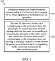
- FIG. 3 illustrates a flow diagram of an embodiment of the step 203 in FIG. 2 .
- the embodiment of FIG. 3 may include step 301 and step 302.
- step 203 starts from step 301.
- step 301 whether the connection status corresponding to the electronic devices point to the restart operation or the force-shutdown operation is determined. Then, the embodiment of step 203 proceeds to step 302.
- step 302 the electronic devices corresponding to the connection status not pointing to the restart operation are removed from the pairing candidate lists corresponding to the controlled elements in the restart group, and the electronic devices corresponding to the connection status not pointing to the force-shutdown operation are removed from the pairing candidate lists corresponding to the controlled elements in the force-shutdown group.
- connection status pointing to the restart operation must include the online notification and the offline notification at the same time.
- each connection status of the electronic devices removed from the pairing candidate lists corresponding to the controlled elements in the restart group does not include the online notification and the offline notification at the same time.
- connection status pointing to the force-shutdown operation must include the unknown notification, and must not include the online notification or the offline notification.
- each connection status of the electronic devices removed from the pairing candidate lists corresponding to the controlled elements in the force-shutdown group may include the online notification or the offline notification, or may not include the unknown notification.
- the following description will take the communication environment 10 illustrated in FIG. 1 as an example to elaborate on the process of using the method 20 illustrated in FIG. 2 to pair each of the controlled elements and each of the electronic devices.
- the controlled elements to be paired are the controlled element 101, the controlled element 103, the controlled element 105, the controlled element 107, and the controlled element 109 in FIG. 1 .
- the controlled elements to be paired are shown to be connected to the electronic device 102, the electronic device 104, the electronic device 106, the electronic device 108, and the electronic device 110 respectively in FIG. 1 , it is only for readers to readily understand the actual paring relationship between the controlled elements and the electronic devices.
- the remote pairing device 100 does not know the pairing relationship between the controlled elements and the electronic devices yet, until the method 20 is completed.
- the remote pairing device may send the restart command to the controlled element 101, the controlled element 103, the controlled element 105, the controlled element 107, and the controlled element 109, to cause the controlled element 101, the controlled element 103, the controlled element 105, the controlled element 107, and the controlled element 109 performs the restart operation on the electronic device 102, the electronic device 104, the electronic device 106, the electronic device 108, and the electronic device 110 respectively, and then observe the connection status received during the second specific time period (e.g., three minutes) after sending the restart command, so as to determine the pairing candidate lists each corresponding to the controlled element 101, the controlled element 103, the controlled element 105, the controlled element 107, and the controlled element 109.
- the second specific time period e.g., three minutes
- the electronic devices corresponding to the connection status not pointing to the restart operation can't be the one paired with the controlled element 101, the controlled element 103, the controlled element 105, the controlled element 107, or the controlled element 109, so they will not be listed in the pairing candidate lists each corresponding to the controlled elements. It is assumed hereby that among the 100 electronic devices, besides the electronic device 102, the electronic device 104, the electronic device 106, the electronic device 108, and the electronic device 110, the electronic device A and the electronic device B also happen to restart soon after the remote pairing device 100 sends the restart command.
- the pairing candidate lists each corresponding to the controlled element 101, the controlled element 103, the controlled element 105, the controlled element 107, and the controlled element 109 are as shown in Table I below.
- Table I Controlled Element Paring Candidate List controlled element 101 electronic device 102, electronic device 104, electronic device 106, electronic device 108, electronic device 110, electronic device A, electronic device B controlled element 103 electronic device 102, electronic device 104, electronic device 106, electronic device 108, electronic device 110, electronic device A, electronic device B controlled element 105 electronic device 102, electronic device 104, electronic device 106, electronic device 108, electronic device 110, electronic device A, electronic device B controlled element 107 electronic device 102, electronic device 104, electronic device 106, electronic device 108, electronic device 110, electronic device A, electronic device B controlled element 109 electronic device 102, electronic device 104, electronic device 106, electronic device 108, electronic device 110, electronic device A, electronic device B controlled element 109 electronic device 102, electronic device 104, electronic device 106, electronic device
- step 201 the controlled element 101, the controlled element 103, the controlled element 105, the controlled element 107, and the controlled element 109 are sorted into the restart group or the force-shutdown group.
- the controlled element 101 at the first, the controlled element 105 at the third, and the controlled element 109 at the fifth are assigned to the restart group, while the controlled element 103 at the second order and the controlled element 207 at the fourth order are assigned to the force-shutdown group.
- the method proceeds to step 202.
- step 202 the remote pairing device 100 will send the restart command to the controlled element 101, the controlled element 105, and the controlled element 109 in the restart group, to cause the controlled element 101, the controlled element 105, and the controlled element 109 to perform the restart operation on the electronic device 102, the electronic device 106, and the electronic device 110 connected thereto respectively.
- the remote pairing device 100 will send the force-shutdown command to the controlled element 103 and the controlled element 107 in the force-shutdown group, to cause the controlled element 103 and the controlled element 107 to perform the force-shutdown operation on the electronic device 104 and the electronic device 108 connected thereto respectively.
- the method proceeds to step 203.
- connection status corresponding to the electronic device 102, the electronic device 106, and the electronic device 110 received by the remote pairing device 100 will point to the restart operation but not the force-shutdown operation, while the connection status corresponding to the electronic device 104 and the electronic device 108 received by the remote pairing device 100 will point to the force-shutdown operation but not the restart operation.
- step 203 the electronic device 104 and the electronic device 108 of which the connection status not pointing to the restart operation will be removed from the pairing candidate lists each corresponding to the controlled element 101, the controlled element 105, and the controlled element 109 in the restart group, while the electronic device 102, the electronic device 106, and the electronic device 110 of which the connection status not pointing to the force-shutdown operation will be removed from the pairing candidate lists each corresponding to controlled element 103 and the controlled element 107 in the force-shutdown group.
- the electronic device A and the electronic device B since the electronic device A and the electronic device B is not connected to any of the controlled element 101, the controlled element 103, the controlled element 105, the controlled element 107, and the controlled element 109, these controlled elements will not cause the electronic device A and the electronic device B to restart or to force shut down. Furthermore, it is assumed hereby that the electronic device A and the electronic device B does not restart or force shut down for other reasons during the second specific time period, and thus the connection status corresponding to them will not point to the restart operation or the force-shutdown operation, so the electronic device A and the electronic device B will be removed from the pairing candidate lists each corresponding to the controlled element 101, the controlled element 103, the controlled element 105, the controlled element 107, and the controlled element 109.
- the method proceeds to step 204.
- the pairing candidate lists each corresponding to the controlled element 101, the controlled element 103, the controlled element 105, the controlled element 107, and the controlled element 109 are as shown in Table II below.
- Table II> Controlled Element Paring Candidate List controlled element 101 electronic device 102, electronic device 106, electronic device 110 controlled element 103 electronic device 104, electronic device 108 controlled element 105 electronic device 102, electronic device 106, electronic device 110 controlled element 107 electronic device 104, electronic device 108 controlled element 109 electronic device 102, electronic device 106, electronic device 110
- step 204 since the pairing candidates lists each corresponding to the controlled element 101, the controlled element 103, the controlled element 105, the controlled element 107, and the controlled element 109 have more than one electronic device (as shown in Table II above), no controlled element is determined to be successfully paired yet. Then, the method proceeds to step 205.
- step 205 since no controlled element is determined to be successfully paired yet at this moment, the method just proceeds to step 206.
- step 206 since there are controlled elements (i.e., the controlled element 101, the controlled element 103, the controlled element 105, the controlled element 107, and the controlled element 109) not determined to be successfully paired yet, the method returns to step 201.
- controlled elements i.e., the controlled element 101, the controlled element 103, the controlled element 105, the controlled element 107, and the controlled element 109
- step 201 the controlled element 101, the controlled element 103, the controlled element 105, the controlled element 107, and the controlled element 109 will be divided into the restart group and the force-shutdown group again.
- the controlled element 101, the controlled element 103, the controlled element 105, the controlled element 107, and the controlled element 109 are sorted first, based on the similarity between the pairing candidate lists each corresponding to these controlled elements, such that the two controlled elements having higher similarity (i.e., the two pairing candidate lists having higher ratio of the same electronic devices) are arranged nearer from each other.
- the pairing candidate lists each corresponding to the controlled element 101, the controlled element 105, and the controlled element 109 have the same electronic devices (i.e., the electronic device 102, the electronic device 106, and the electronic device 110, as shown in Table II above), while the pairing candidate lists each corresponding to the controlled element 103 and the controlled element 107 have the electronic devices (i.e., the electronic device 104 and the electronic device 108), the order of these controlled elements set to be "controlled element 101, controlled element 105, controlled element 109, controlled element 103, controlled element 107".
- the controlled element 101 at the first order, the controlled element 109 at the third order, and the controlled element 107 at the fifth order are then interweavingly assigned to the restart group, while the controlled element 105 at the second order and the controlled element 103 at the fourth order are assigned to the force-shutdown group. Then, the method proceeds to step 202.
- step 202 the remote pairing device 100 will send the restart command to the controlled element 101, the controlled element 107, and the controlled element 109 in the restart group, to cause the controlled element 101, the controlled element 107, and the controlled element 109 to perform the restart operation on the electronic device 102, the electronic device 108, and the electronic device 110 connected thereto respectively.
- the remote pairing device 100 will send the force-shutdown command to the controlled element 103 and the controlled element 105, to cause the controlled element 103 and the controlled element 105 to perform the restart operation on the electronic device 104 and the electronic device 106 connected thereto respectively.
- the method proceeds to step 203.
- connection status corresponding to the electronic device 102, the electronic device 108, and the electronic device 110 received by the remote pairing device 100 will point to the restart operation but not the force-shutdown operation, while the connection status corresponding to the electronic device 104 and the electronic device 106 received by the remote pairing device 100 will point to the force-shutdown operation but not the restart operation.
- step 203 the electronic device 104 and the electronic device 106 of which the connection status not pointing to the restart operation will be removed from the pairing candidate lists each corresponding to the controlled element 101, the controlled element 107, and the controlled element 109 in the restart group, while the electronic device 102, the electronic device 108, and the electronic device 110 of which the connection status not pointing to the force-shutdown operation will be removed from the pairing candidate lists each corresponding to the controlled element 103 and the controlled element 105 in the force-shutdown group.
- the method proceeds to step 204.
- the pairing candidate lists each corresponding to the controlled element 101, the controlled element 103, the controlled element 105, the controlled element 107, and the controlled element 109 are as shown in Table III below.
- Table II> Controlled Element Paring Candidate List controlled element 101 electronic device 102, electronic device 110 controlled element 103 electronic device 104 controlled element 105 electronic device 106 controlled element 107 electronic device 108 controlled element 109 electronic device 102, electronic device 110
- step 204 since the pairing candidates lists each corresponding to the controlled element 103, the controlled element 105, and the controlled element 107 all have only one electronic device, the controlled element 103, the controlled element 105, and the controlled element 107 are determined to be successfully paired. In other words, at this moment, it is known that the controlled element 103 is paired with the electronic device 104, the controlled element 105 is paired with the electronic device 106, and the controlled element 107 is paired with the electronic device 108. Then, the method proceeds to step 205.
- step 205 the electronic device 104 paired with the controlled element 103, the electronic device 10 paired with the controlled element 105, and the electronic device 108 paired with the controlled element 107 are removed from the pairing candidate list corresponding to other controlled elements, and the controlled element 103, the controlled element 105, and the controlled element 107 are ruled out from subsequent calculation. Then, the method proceeds to step 206.
- step 206 since there are controlled elements (i.e., the controlled element 101 and the controlled element 109) not determined to be successfully paired yet, the method returns to step 201.
- step 201 the controlled element 101 and the controlled element 109 will be divided into the restart group and the force-shutdown group again.
- the controlled element 101 is assigned to the restart group
- the controlled element 109 is assigned to the force-shutdown group. Then, the method proceeds to step 202.
- step 202 the remote pairing device will send the restart command to the controlled element 101 in the restart group, to cause the controlled element 101 to perform the restart operation on the electronic device 102 connected thereto.
- the remote pairing device 100 will send the force-shutdown operation to the controlled element 109 in the force-shutdown group, to cause the controlled element 109 to perform the force-shutdown operation on the electronic device 110 connected thereto. Then, the method proceeds to step 203.
- step 203 the electronic device 110 of which the connection status not pointing to the restart operation will be removed from the pairing candidate list corresponding to the controlled element 101 in the restart group, while the electronic device 102 of which the connection status not pointing to the force-shutdown operation will be removed from the pairing candidate list corresponding to the controlled element 109 in the force-shutdown group.
- step 204 the pairing candidate lists each corresponding to the controlled element 101 and the controlled element 109 are as shown in Table IV below.
- step 204 since the pairing candidates lists each corresponding to the controlled element 101 and the controlled element 109 both have only one electronic device, the controlled element 101 and the controlled element 109 are determined to be successfully paired. In other words, at this moment, it is known that the controlled element 101 is paired with the electronic device 102, and the controlled element 109 is paired with the electronic device 108. Then, the method proceeds to step 205.
- step 205 the electronic device 102 paired with the controlled element 101, and the electronic device 110 paired with the controlled element 109 are removed from the pairing candidate lists corresponding to other controlled elements, and the controlled element 101 and the controlled element 109 are ruled out from subsequent calculation. Then, the method proceeds to step 206.
- step 206 since the controlled element 101, the controlled element 103, the controlled element 105, the controlled element 107, and the controlled element 109 are all determined to be successfully paired, the remote pairing device 100 will end the pairing process.
- the remote pairing device and method provided by the present disclosure allows the remote control site to figure out the pairing relationship between these controlled elements and the electronic devices when there are multiple controlled elements each set up on multiple electronic devices, so that the control commands from the remote site are transmitted to the correct electronic devices.
Landscapes
- Engineering & Computer Science (AREA)
- Theoretical Computer Science (AREA)
- Software Systems (AREA)
- Computer Networks & Wireless Communication (AREA)
- Signal Processing (AREA)
- General Physics & Mathematics (AREA)
- General Engineering & Computer Science (AREA)
- Physics & Mathematics (AREA)
- Computer Security & Cryptography (AREA)
- Quality & Reliability (AREA)
- Multimedia (AREA)
- Selective Calling Equipment (AREA)
- Telephone Function (AREA)
Abstract
Description
- This Application claims priority of
Taiwan Patent Application No. 110111871, filed on March 31, 2021 - The present disclosure is related to a pairing device and method, and in particular it is related to a remote pairing device and method.
- Nowadays, there is a need for many enterprises to boot or shutdown their remote electronic devices. The uncertainty of network stability occasionally results in an inability to remotely control these electronic devices. Furthermore, when an electronic device crashes, users may not be able to perform a restart operation on it. In order to solve the problems described above, some firms may provide an additional element for the electronic device. Directly performing the booting or shutdown operation on an electronic device from the hardware site is allowed by setting up a controlled element on the mainboard of the electronic device and connecting the controlled element to the power pins of the mainboard. In addition, the controlled element itself may have independent network connection capability, so that the controlled element and the electronic device can use different networks. This provides a redundancy option for the remote-control site to perform the booting or shutdown operation on the electronic device via another network when the electronic device is disconnected.
- However, since the controlled element and the electronic device use different networks, and there is no connection between the controlled element and the electronic device other than the power pins. Hence, this raises a problem that needs to be solved: when there are multiple controlled elements each set up on multiple electronic devices, how does the control site figure out the pairing relationship between these controlled elements and the electronic devices?
- In order to overcome the problem described above, the present disclosure provides a remote pairing device and method, allowing the remote site to figure out the pairing relationship between the controlled elements and the electronic devices.
- An embodiment of the present disclosure provides a remote pairing device, including a processor. The processor executes the following tasks. A plurality of controlled elements is divided into a restart group and a force-shutdown group. The controlled elements are each connected to a plurality of electronic devices. A restart command is sent to the controlled elements in the restart group, to cause the controlled elements in the restart group to perform a restart operation on the electronic devices connected thereto. A force-shutdown command is sent to the controlled elements in the force-shutdown group, to cause the controlled elements in the force-shutdown group to perform a force-shutdown operation on the electronic devices connected thereto. A plurality of pairing candidate lists each corresponding to the controlled elements is updated according to a plurality of connection statuses each corresponding to the electronic devices received during a specific time period after sending the restart command or the force-shutdown command. A determination is made that the controlled elements corresponding to the pairing candidates lists having only one of the electronic devices therein are successfully-paired The above steps are repeated until all of the controlled elements are successfully paired.
- In some embodiments, the step of updating the pairing candidate lists each corresponding to the controlled elements according to the connection status each corresponding to the electronic devices received during the specific time period after sending the restart command or the force-shutdown command includes the following steps. It is determined whether each of the connection statuses corresponding to each of the electronic devices points to a restart operation or a force-shutdown operation. The electronic devices each corresponding to the connection status that do not point to a restart operation are removed from the pairing candidate lists each corresponding to the controlled elements in the restart group. The electronic devices each corresponding to the connection status that do not point to a force-shutdown operation are removed from the pairing candidate lists each corresponding to the controlled elements in the force-shutdown group.
- In some embodiments, each connection status that points to a restart operation includes an online notification and an offline notification. Each connection status that points to a force-shutdown operation includes an unknown notification, and does not include the online notification or the offline notification.
- In some embodiments, the processor further executes the following steps. It removes the only electronic device in the pairing candidate lists corresponding to the controlled elements that has successfully paired from the pairing candidate lists having a plurality of the electronic devices therein. It rules out the controlled elements that have successfully paired from subsequent calculations.
- In some embodiments, the electronic device and the controlled element communicate with the remote pairing device via different networks.
- In addition, an embodiment of the present disclosure provides a remote pairing method, including the following steps. A plurality of controlled elements is divided into a restart group and a force-shutdown group. The controlled elements are each connected to a plurality of electronic devices. A restart command is sent to the controlled elements in the restart group, to cause the controlled elements in the restart group to perform a restart operation on the electronic devices connected to the controlled elements in the restart group. A force-shutdown command is sent to the controlled elements in the force-shutdown group, to cause the controlled elements in the force-shutdown group to perform a force-shutdown operation on the electronic devices connected to the controlled elements in the force-shutdown group. A plurality of pairing candidate lists each corresponding to the controlled elements are updated according to a plurality of connection statuses each corresponding to the electronic devices received during a specific time period after sending the restart command or the force-shutdown command. A determination is made that the controlled elements corresponding to the pairing candidates lists having only one of the electronic devices therein are successfully-paired. The above steps are repeated until all of the controlled elements are successfully paired.
- In some embodiments, the remote pairing method further includes the following steps. The only electronic device in the pairing candidate lists corresponding to the controlled elements that is successfully paired is removed from the pairing candidate lists having a plurality of the electronic devices therein. The controlled elements that have successfully paired are ruled out from subsequent calculations.
- The remote pairing device and method provided by the present disclosure allows the remote control site to figure out the pairing relationship between these controlled elements and the electronic devices when there are multiple controlled elements and multiple electronic devices, so that the control commands from the remote site are transmitted to the correct electronic devices.
- The present disclosure can be more fully understood by reading the subsequent detailed description and examples with references made to the accompanying drawings, wherein:
-
FIG. 1 illustrates a network architecture diagram of acommunication environment 10 in which an exemplaryremote pairing device 100 is operating, according to an embodiment of the present disclosure; -
FIG. 2 illustrates a flow diagram of aremote pairing method 20 executed by theremote pairing device 100 inFIG. 1 , according to an embodiment of the present disclosure; and -
FIG. 3 illustrates a flow diagram of an embodiment of thestep 203 inFIG. 2 . -
FIG. 1 illustrates a network architecture diagram of acommunication environment 10 in which an exemplaryremote pairing device 100 is operating, according to an embodiment of the present disclosure. As shown inFIG. 1 , thecommunication environment 10 includes not only theremote pairing device 100, but also a controlledelement 101, a controlledelement 103, a controlledelement 105, a controlledelement 107, a controlledelement 109, anelectronic device 102, anelectronic device 104, anelectronic device 106, anelectronic device 108, anelectronic device 110, and acloud connection system 130. In thecommunication environment 10, the controlledelement 101, the controlledelement 103, the controlledelement 105, the controlledelement 107, and the controlledelement 109 are respectively connected to thecloud connection system 130 via anetwork 111, anetwork 113, anetwork 115, anetwork 117, and anetwork 119. Theelectronic device 102, theelectronic device 104, theelectronic device 106, theelectronic device 108, and theelectronic device 110 are respectively connected to thecloud connection system 130 via anetwork 112, anetwork 114, anetwork 116, anetwork 118, and anetwork 120. The controlledelement 101, the controlledelement 103, the controlledelement 105, the controlledelement 107, and the controlledelement 109 are respectively set up on the mainboard (not shown inFIG. 1 ) of theelectronic device 102, theelectronic device 104, theelectronic device 106, theelectronic device 108, and theelectronic device 110, and connected to the power pins of the mainboard. Thecloud connection system 130 is connected to theremote pairing device 100 by wire or wirelessly. - According to an embodiment of the present disclosure, the
electronic device 102, theelectronic device 104, theelectronic device 106, theelectronic device 108, theelectronic device 110, and theremote pairing device 100 in thecommunication environment 10 can be any device that includes a processor (not shown inFig. 1 ) and communicates with other devices through a network, such as various desktops, laptops, servers, mobile devices, workstations, or terminals. The processor can be any device that is used for executing commands, such as a CPU, a microprocessor, a controller, a microcontroller, or a state machine, although embodiments of the present disclosure are not limited thereto. - According to an embodiment of the present disclosure, the
cloud connection system 130 in thecommunication environment 10 can be a cloud infrastructure such as a private cloud, a public cloud, and/or a mixed cloud. Thecloud connection system 130 may include one or more computerized devices, and each computerized device may include hardware elements that are electrically coupled via bus. The hardware elements may include at least one central processing unit (CPU), at least one input device (such as a mouse, a keyboard, a touch screen, or a small keyboard), and at least one output device (such as a display device, a printer, or a loudspeaker). Thecloud connection system 130 may also include one or more storage devices, such as disk drivers, optical storage elements, and solid-state storage devices like random access memory (RAM), read-only memory (ROM), removable media devices, memory cards, flash memory cards, etc. - According to an embodiment of the present disclosure, the network 111-120 can be, for example, a local area network (LAN), a wide area network (WAN), a virtual private network, the Internet, an intranet, an extranet, a public switched telephone network, an infrared network, a wireless network, and/or any combination thereof.
- According to an embodiment of the present disclosure, each of the controlled
element 101, the controlledelement 103, the controlledelement 105, the controlledelement 107, and the controlledelement 109 in thecommunication environment 10 can be an external power that includes a rechargeable battery, and can be set up on the mainboard of the electronic device. By connecting to the power pins of the mainboard of each electronic device, the controlledelement 101, the controlledelement 103, the controlledelement 105, the controlledelement 107, and the controlledelement 109 are allowed to directly perform the booting or shutdown operation on theelectronic device 102, theelectronic device 104, theelectronic device 106, theelectronic device 108, and theelectronic device 110 connected thereto respectively. The controlledelement 101, the controlledelement 103, the controlledelement 105, the controlledelement 107, and the controlledelement 109 further have network connection capability, allowing receiving the control command from the remote site (e.g., the remote pairing device 100) through thenetwork 111, thenetwork 113, thenetwork 115, thenetwork 117, and thenetwork 119. - According to an embodiment of the present disclosure, the cloud connection system in the
communication environment 10 may collect the connection information returned by theelectronic device 102, theelectronic device 104, theelectronic device 106, theelectronic device 108, and theelectronic device 110, via thenetwork 112, thenetwork 114, thenetwork 116, thenetwork 118, and thenetwork 120 respectively. Thecloud connection system 130 may send a status notification corresponding to each of the electronic devices based on the connection information returned by each of the electronic devices. In some embodiments, in response to theelectronic device 102 having just connected to the cloud connection system 130 (e.g., booting), thecloud connection system 130 will send an online notice corresponding to theelectronic device 102 to theremote pairing device 100. In response to theelectronic device 102 voluntarily disconnecting from the cloud connection system 130 (e.g., normal shutdown), thecloud connection system 130 will send an offline notification corresponding to theelectronic device 102 to theremote pairing device 100. In response to theelectronic device 102 involuntarily disconnecting from the cloud connection system 130 (e.g., abnormal shutdown, system failure, or the network wire being unplugged), thecloud connection system 130 will send an unknown notification corresponding to theelectronic device 102 to theremote pairing device 100 after a first specific time period (e.g., one minute, although embodiments of the present disclosure are not limited thereto) from when the disconnection happens. For any electronic devices in thecommunication environment 10 other than theelectronic device 102, such as theelectronic device 104, theelectronic device 106, theelectronic device 108, theelectronic device 110, and/or other electronic devices that are not shown inFIG. 1 , the behavior of thecloud connection system 130 is the same as described above. Thus, theremote pairing device 100 can figure out the connection status of each electronic device based on the status notification that has been received. - As previously described, for the present application, the problem to be overcome is how the control site figure out the pairing relationship between the controlled elements and the electronic devices when there are multiple controlled elements each set up on multiple electronic devices. For example, how does the control site (i.e., the remote pairing device 100) figure out that the controlled
element 101, the controlledelement 103, the controlledelement 105, the controlledelement 107, and the controlledelement 109 are connected to theelectronic device 102, theelectronic device 104, theelectronic device 106, theelectronic device 108, and theelectronic device 110 respectively in thecommunication environment 10. - The
remote pairing device 100 provided by the present disclosure may send a restart command or a force-shutdown command to the controlled element of each electronic device in thecommunication environment 10, and thereby filter a pairing candidate list (i.e., the list of all the electronic devices that are possible to be connected with the controlled element) corresponding to each controlled element according to the connection status corresponding to each controlled element that is received during a second specific time period (e.g., three minutes, although embodiments of the present disclosure are not limited thereto, as long as the second specific time period is longer than the first specific time period) after sending the restart command or the force-shutdown command. After filtering the pairing candidate list for sufficient number of times, the electronic device connected to each controlled element will be figured out. - For example, the
remote pairing device 100 may send the restart command to the controlledelement 101, to cause the controlledelement 101 to perform a restart operation on theelectronic device 102. In other words, the electronic device will shut down first, and then boot again. In response to theelectronic device 102 shutting down, theremote pairing device 100 will receive the offline notification corresponding to theelectronic device 102. In response to theelectronic device 102 booting up, theremote pairing device 100 will also receive an online notification corresponding to theelectronic device 102. Theremote pairing device 100 may then remove the electronic devices corresponding to the connection status (which does not include an online notification and an offline notification) received during the second specific time period (e.g., three minutes) after sending the restart command from the pairing candidate list corresponding to the controlledelement 101. This is because the electronic devices corresponding to the connection status (that does not include an online notification and an offline notification) have not restarted during the second specific time period, and so they can't be the electronic device connected to the controlledelement 101. - In another example, the
remote pairing device 100 may send the force-shutdown command to the controlledelement 103, to cause the controlledelement 103 to perform a force-shutdown operation on theelectronic device 104. In response to theelectronic device 104 shutting down, theremote pairing device 100 will receive the unknown notification corresponding to theelectronic device 104 after the first specific time period (e.g., one minute). Theremote pairing device 100 may then remove the electronic devices corresponding to the connection status received during the second specific time period (e.g., three minutes) after sending the force-shutdown command that do not include the unknown notification and that includes the online notification or the offline notification from the pairing candidate list corresponding to the controlledelement 103. This is because the electronic devices corresponding to the connection status not including the unknown notification have not been force shutdown during the second specific time period, and so they can't be the electronic device connected to the controlledelement 103. Also, the electronic devices corresponding to the connection status including the online notification or the offline notification can't be the electronic device connected to the controlledelement 103, because the electronic devices are not possible to have the booting behavior or the shutdown behavior during the second specific time period after being shut down. -
FIG. 2 illustrates a flow diagram of aremote pairing method 20 executed by theremote pairing device 100 inFIG. 1 , according to an embodiment of the present disclosure. As shown inFIG. 2 , theremote pairing method 20 includes steps 201-206. - The
remote pairing method 20 starts fromstep 201. Instep 201, a plurality of controlled elements are divided into a restart group and a force-shutdown group, wherein the each of the controlled elements is connected to an electronic device. Then, theremote pairing method 20 proceeds to step 202. - In
step 202, a restart command is sent to the controlled elements in the restart group, to cause the controlled elements in the restart group to perform a restart operation on the electronic devices connected to the controlled elements in the restart group; and a force-shutdown command is sent to the controlled elements in the force-shutdown group, to cause the controlled elements in the force-shutdown group to perform a force-shutdown operation on the electronic devices connected to the controlled elements in the force-shutdown group. Then, theremote pairing method 20 proceeds to step 203. - In
step 203, a candidate list corresponding to each of the controlled elements is updated, according to the connection status corresponding to each of the electronic devices received during the second specific time period after sending the restart command or the force-shutdown command. Each candidate list may have one or more electronic devices. Then, theremote pairing method 20 proceeds to step 204. - In
step 204, the controlled elements corresponding to the pairing candidates lists having only one electronic device are determined to be successfully paired. Then, theremote pairing method 20 proceeds to step 205. - In
step 205, the only electronic device in the pairing candidate lists corresponding to the successfully paired controlled elements is removed from the pairing candidate lists having a plurality of the electronic devices therein, and the successfully paired controlled elements are ruled out from subsequent calculation. Then, theremote pairing method 20 proceeds to step 206. - In
step 206, a check is made whether all of the controlled elements are successfully paired. In other words, it is checked whether all of the controlled elements are ruled out from subsequent calculation. If yes, then theremote pairing method 20 ends. If not, it is indicated that there are controlled elements that have not been successfully paired yet, and theremote pairing method 20 returns to step 201. -
FIG. 3 illustrates a flow diagram of an embodiment of thestep 203 inFIG. 2 . As shown inFIG. 3 , the embodiment ofFIG. 3 may includestep 301 andstep 302. - The embodiment of
step 203 starts fromstep 301. Instep 301, whether the connection status corresponding to the electronic devices point to the restart operation or the force-shutdown operation is determined. Then, the embodiment ofstep 203 proceeds to step 302. - In
step 302, the electronic devices corresponding to the connection status not pointing to the restart operation are removed from the pairing candidate lists corresponding to the controlled elements in the restart group, and the electronic devices corresponding to the connection status not pointing to the force-shutdown operation are removed from the pairing candidate lists corresponding to the controlled elements in the force-shutdown group. - In some embodiments, the connection status pointing to the restart operation must include the online notification and the offline notification at the same time. In other words, in
step 302, each connection status of the electronic devices removed from the pairing candidate lists corresponding to the controlled elements in the restart group does not include the online notification and the offline notification at the same time. - In some embodiments, the connection status pointing to the force-shutdown operation must include the unknown notification, and must not include the online notification or the offline notification. In other words, in
step 302, each connection status of the electronic devices removed from the pairing candidate lists corresponding to the controlled elements in the force-shutdown group may include the online notification or the offline notification, or may not include the unknown notification. - The following description will take the
communication environment 10 illustrated inFIG. 1 as an example to elaborate on the process of using themethod 20 illustrated inFIG. 2 to pair each of the controlled elements and each of the electronic devices. In this example, it is assumed that in thecommunication environment 10, there are 100 electronic devices (not all of these devices are shown inFIG. 1 ) connected to thecloud connection system 130, and the controlled elements to be paired are the controlledelement 101, the controlledelement 103, the controlledelement 105, the controlledelement 107, and the controlledelement 109 inFIG. 1 . It should be appreciated that although the controlled elements to be paired are shown to be connected to theelectronic device 102, theelectronic device 104, theelectronic device 106, theelectronic device 108, and theelectronic device 110 respectively inFIG. 1 , it is only for readers to readily understand the actual paring relationship between the controlled elements and the electronic devices. In this example, it is assumed that theremote pairing device 100 does not know the pairing relationship between the controlled elements and the electronic devices yet, until themethod 20 is completed. - First, the remote pairing device may send the restart command to the controlled
element 101, the controlledelement 103, the controlledelement 105, the controlledelement 107, and the controlledelement 109, to cause the controlledelement 101, the controlledelement 103, the controlledelement 105, the controlledelement 107, and the controlledelement 109 performs the restart operation on theelectronic device 102, theelectronic device 104, theelectronic device 106, theelectronic device 108, and theelectronic device 110 respectively, and then observe the connection status received during the second specific time period (e.g., three minutes) after sending the restart command, so as to determine the pairing candidate lists each corresponding to the controlledelement 101, the controlledelement 103, the controlledelement 105, the controlledelement 107, and the controlledelement 109. Among the 100 electronic devices, the electronic devices corresponding to the connection status not pointing to the restart operation can't be the one paired with the controlledelement 101, the controlledelement 103, the controlledelement 105, the controlledelement 107, or the controlledelement 109, so they will not be listed in the pairing candidate lists each corresponding to the controlled elements. It is assumed hereby that among the 100 electronic devices, besides theelectronic device 102, theelectronic device 104, theelectronic device 106, theelectronic device 108, and theelectronic device 110, the electronic device A and the electronic device B also happen to restart soon after theremote pairing device 100 sends the restart command. At this moment, the pairing candidate lists each corresponding to the controlledelement 101, the controlledelement 103, the controlledelement 105, the controlledelement 107, and the controlledelement 109 are as shown in Table I below.<Table I> Controlled Element Paring Candidate List controlled element 101electronic device 102,electronic device 104,electronic device 106,electronic device 108,electronic device 110, electronic device A, electronic device Bcontrolled element 103electronic device 102,electronic device 104,electronic device 106,electronic device 108,electronic device 110, electronic device A, electronic device Bcontrolled element 105electronic device 102,electronic device 104,electronic device 106,electronic device 108,electronic device 110, electronic device A, electronic device Bcontrolled element 107electronic device 102,electronic device 104,electronic device 106,electronic device 108,electronic device 110, electronic device A, electronic device Bcontrolled element 109electronic device 102,electronic device 104,electronic device 106,electronic device 108,electronic device 110, electronic device A, electronic device B - Then, in
step 201, the controlledelement 101, the controlledelement 103, the controlledelement 105, the controlledelement 107, and the controlledelement 109 are sorted into the restart group or the force-shutdown group. In this embodiment, based on the order of "controlledelement 101, controlledelement 103, controlledelement 105, controlledelement 107, controlledelement 109", the controlledelement 101 at the first, the controlledelement 105 at the third, and the controlledelement 109 at the fifth are assigned to the restart group, while the controlledelement 103 at the second order and the controlled element 207 at the fourth order are assigned to the force-shutdown group. Then, the method proceeds to step 202. - In
step 202, theremote pairing device 100 will send the restart command to the controlledelement 101, the controlledelement 105, and the controlledelement 109 in the restart group, to cause the controlledelement 101, the controlledelement 105, and the controlledelement 109 to perform the restart operation on theelectronic device 102, theelectronic device 106, and theelectronic device 110 connected thereto respectively. Theremote pairing device 100 will send the force-shutdown command to the controlledelement 103 and the controlledelement 107 in the force-shutdown group, to cause the controlledelement 103 and the controlledelement 107 to perform the force-shutdown operation on theelectronic device 104 and theelectronic device 108 connected thereto respectively. Then, the method proceeds to step 203. - During the second specific time period after sending the commands, the connection status corresponding to the
electronic device 102, theelectronic device 106, and theelectronic device 110 received by theremote pairing device 100 will point to the restart operation but not the force-shutdown operation, while the connection status corresponding to theelectronic device 104 and theelectronic device 108 received by theremote pairing device 100 will point to the force-shutdown operation but not the restart operation. In view of the above, instep 203, theelectronic device 104 and theelectronic device 108 of which the connection status not pointing to the restart operation will be removed from the pairing candidate lists each corresponding to the controlledelement 101, the controlledelement 105, and the controlledelement 109 in the restart group, while theelectronic device 102, theelectronic device 106, and theelectronic device 110 of which the connection status not pointing to the force-shutdown operation will be removed from the pairing candidate lists each corresponding to controlledelement 103 and the controlledelement 107 in the force-shutdown group. Besides, since the electronic device A and the electronic device B is not connected to any of the controlledelement 101, the controlledelement 103, the controlledelement 105, the controlledelement 107, and the controlledelement 109, these controlled elements will not cause the electronic device A and the electronic device B to restart or to force shut down. Furthermore, it is assumed hereby that the electronic device A and the electronic device B does not restart or force shut down for other reasons during the second specific time period, and thus the connection status corresponding to them will not point to the restart operation or the force-shutdown operation, so the electronic device A and the electronic device B will be removed from the pairing candidate lists each corresponding to the controlledelement 101, the controlledelement 103, the controlledelement 105, the controlledelement 107, and the controlledelement 109. Then, the method proceeds to step 204. At this moment, the pairing candidate lists each corresponding to the controlledelement 101, the controlledelement 103, the controlledelement 105, the controlledelement 107, and the controlledelement 109 are as shown in Table II below.<Table II> Controlled Element Paring Candidate List controlled element 101electronic device 102,electronic device 106,electronic device 110controlled element 103electronic device 104,electronic device 108controlled element 105electronic device 102,electronic device 106,electronic device 110controlled element 107electronic device 104,electronic device 108controlled element 109electronic device 102,electronic device 106,electronic device 110 - In
step 204, since the pairing candidates lists each corresponding to the controlledelement 101, the controlledelement 103, the controlledelement 105, the controlledelement 107, and the controlledelement 109 have more than one electronic device (as shown in Table II above), no controlled element is determined to be successfully paired yet. Then, the method proceeds to step 205. - In
step 205, since no controlled element is determined to be successfully paired yet at this moment, the method just proceeds to step 206. - In
step 206, since there are controlled elements (i.e., the controlledelement 101, the controlledelement 103, the controlledelement 105, the controlledelement 107, and the controlled element 109) not determined to be successfully paired yet, the method returns to step 201. - In
step 201, the controlledelement 101, the controlledelement 103, the controlledelement 105, the controlledelement 107, and the controlledelement 109 will be divided into the restart group and the force-shutdown group again. In this embodiment, the controlledelement 101, the controlledelement 103, the controlledelement 105, the controlledelement 107, and the controlledelement 109 are sorted first, based on the similarity between the pairing candidate lists each corresponding to these controlled elements, such that the two controlled elements having higher similarity (i.e., the two pairing candidate lists having higher ratio of the same electronic devices) are arranged nearer from each other. In this example, in view of the pairing candidate lists each corresponding to the controlledelement 101, the controlledelement 105, and the controlledelement 109 have the same electronic devices (i.e., theelectronic device 102, theelectronic device 106, and theelectronic device 110, as shown in Table II above), while the pairing candidate lists each corresponding to the controlledelement 103 and the controlledelement 107 have the electronic devices (i.e., theelectronic device 104 and the electronic device 108), the order of these controlled elements set to be "controlledelement 101, controlledelement 105, controlledelement 109, controlledelement 103, controlledelement 107". The controlledelement 101 at the first order, the controlledelement 109 at the third order, and the controlledelement 107 at the fifth order are then interweavingly assigned to the restart group, while the controlledelement 105 at the second order and the controlledelement 103 at the fourth order are assigned to the force-shutdown group. Then, the method proceeds to step 202. - In
step 202, theremote pairing device 100 will send the restart command to the controlledelement 101, the controlledelement 107, and the controlledelement 109 in the restart group, to cause the controlledelement 101, the controlledelement 107, and the controlledelement 109 to perform the restart operation on theelectronic device 102, theelectronic device 108, and theelectronic device 110 connected thereto respectively. Theremote pairing device 100 will send the force-shutdown command to the controlledelement 103 and the controlledelement 105, to cause the controlledelement 103 and the controlledelement 105 to perform the restart operation on theelectronic device 104 and theelectronic device 106 connected thereto respectively. Then, the method proceeds to step 203. - During the second specific time period after sending the commands, the connection status corresponding to the
electronic device 102, theelectronic device 108, and theelectronic device 110 received by theremote pairing device 100 will point to the restart operation but not the force-shutdown operation, while the connection status corresponding to theelectronic device 104 and theelectronic device 106 received by theremote pairing device 100 will point to the force-shutdown operation but not the restart operation. In view of the above, instep 203, theelectronic device 104 and theelectronic device 106 of which the connection status not pointing to the restart operation will be removed from the pairing candidate lists each corresponding to the controlledelement 101, the controlledelement 107, and the controlledelement 109 in the restart group, while theelectronic device 102, theelectronic device 108, and theelectronic device 110 of which the connection status not pointing to the force-shutdown operation will be removed from the pairing candidate lists each corresponding to the controlledelement 103 and the controlledelement 105 in the force-shutdown group. Then, the method proceeds to step 204. At this moment, the pairing candidate lists each corresponding to the controlledelement 101, the controlledelement 103, the controlledelement 105, the controlledelement 107, and the controlledelement 109 are as shown in Table III below.<Table II> Controlled Element Paring Candidate List controlled element 101electronic device 102,electronic device 110controlled element 103electronic device 104controlled element 105electronic device 106controlled element 107electronic device 108controlled element 109electronic device 102,electronic device 110 - In
step 204, since the pairing candidates lists each corresponding to the controlledelement 103, the controlledelement 105, and the controlledelement 107 all have only one electronic device, the controlledelement 103, the controlledelement 105, and the controlledelement 107 are determined to be successfully paired. In other words, at this moment, it is known that the controlledelement 103 is paired with theelectronic device 104, the controlledelement 105 is paired with theelectronic device 106, and the controlledelement 107 is paired with theelectronic device 108. Then, the method proceeds to step 205. - In
step 205, theelectronic device 104 paired with the controlledelement 103, theelectronic device 10 paired with the controlledelement 105, and theelectronic device 108 paired with the controlledelement 107 are removed from the pairing candidate list corresponding to other controlled elements, and the controlledelement 103, the controlledelement 105, and the controlledelement 107 are ruled out from subsequent calculation. Then, the method proceeds to step 206. - In
step 206, since there are controlled elements (i.e., the controlledelement 101 and the controlled element 109) not determined to be successfully paired yet, the method returns to step 201. - In
step 201, the controlledelement 101 and the controlledelement 109 will be divided into the restart group and the force-shutdown group again. In this example, the controlledelement 101 is assigned to the restart group, and the controlledelement 109 is assigned to the force-shutdown group. Then, the method proceeds to step 202. - In
step 202, the remote pairing device will send the restart command to the controlledelement 101 in the restart group, to cause the controlledelement 101 to perform the restart operation on theelectronic device 102 connected thereto. Theremote pairing device 100 will send the force-shutdown operation to the controlledelement 109 in the force-shutdown group, to cause the controlledelement 109 to perform the force-shutdown operation on theelectronic device 110 connected thereto. Then, the method proceeds to step 203. - During the second specific time period after sending the commands, the connection status corresponding to the
electronic device 102 received by theremote pairing device 100 will point to the restart operation but not the force-shutdown operation, while the connection status corresponding to theelectronic device 110 received by theremote pairing device 100 will point to the force-shutdown operation but not the restart operation. In view of the above, instep 203, theelectronic device 110 of which the connection status not pointing to the restart operation will be removed from the pairing candidate list corresponding to the controlledelement 101 in the restart group, while theelectronic device 102 of which the connection status not pointing to the force-shutdown operation will be removed from the pairing candidate list corresponding to the controlledelement 109 in the force-shutdown group. Then, the method proceeds to step 204. At this moment, the pairing candidate lists each corresponding to the controlledelement 101 and the controlledelement 109 are as shown in Table IV below.<Table IV> Controlled Element Paring Candidate List controlled element 101electronic device 102controlled element 109electronic device 110 - In
step 204, since the pairing candidates lists each corresponding to the controlledelement 101 and the controlledelement 109 both have only one electronic device, the controlledelement 101 and the controlledelement 109 are determined to be successfully paired. In other words, at this moment, it is known that the controlledelement 101 is paired with theelectronic device 102, and the controlledelement 109 is paired with theelectronic device 108. Then, the method proceeds to step 205. - In
step 205, theelectronic device 102 paired with the controlledelement 101, and theelectronic device 110 paired with the controlledelement 109 are removed from the pairing candidate lists corresponding to other controlled elements, and the controlledelement 101 and the controlledelement 109 are ruled out from subsequent calculation. Then, the method proceeds to step 206. - In
step 206, since the controlledelement 101, the controlledelement 103, the controlledelement 105, the controlledelement 107, and the controlledelement 109 are all determined to be successfully paired, theremote pairing device 100 will end the pairing process. - As per the embodiments described above, the remote pairing device and method provided by the present disclosure allows the remote control site to figure out the pairing relationship between these controlled elements and the electronic devices when there are multiple controlled elements each set up on multiple electronic devices, so that the control commands from the remote site are transmitted to the correct electronic devices.
- Ordinal terms used in the claims, such as "first," "second," "third," etc., are used to modify the elements appearing in the claims, and do not imply any prioritization, precedence relation, or a component is higher than the other component, or the chronological order in which the method steps are performed. The intention is to make a distinction between elements with the same name.
- The above paragraphs are described with multiple aspects. Obviously, the teachings of the specification may be performed in multiple ways. Any specific structure or function disclosed in examples is only a representative situation. According to the teachings of the specification, it should be noted by those skilled in the art that any aspect disclosed may be performed individually, or that more than two aspects could be combined and performed.
- While the invention has been described by way of example and in terms of the preferred embodiments, it should be understood that the invention is not limited to the disclosed embodiments. On the contrary, it is intended to cover various modifications and similar arrangements (as would be apparent to those skilled in the art). Therefore, the scope of the appended claims should be accorded the broadest interpretation so as to encompass all such modifications and similar arrangements.
Claims (9)
- A remote pairing device, comprising a processor to execute:dividing a plurality of controlled elements into a restart group and a force-shutdown group, wherein the controlled elements are each connected to a plurality of electronic devices;sending a restart command to the controlled elements in the restart group, to cause the controlled elements in the restart group to perform a restart operation on the electronic devices connected to the controlled elements in the restart group;sending a force-shutdown command to the controlled elements in the force-shutdown group, to cause the controlled elements in the force-shutdown group to perform a force-shutdown operation on the electronic devices connected to the controlled elements in the force-shutdown group;updating a plurality of pairing candidate lists each corresponding to the controlled elements, according to a plurality of connection statuses each corresponding to the electronic devices received during a specific time period after sending the restart command or the force-shutdown command;determining that the controlled elements corresponding to the pairing candidates lists having only one of the electronic devices therein are successfully-paired;repeating the above steps until all of the controlled elements are successfully paired.
- The remote pairing device as claimed in claim 1, wherein the pairing candidate lists each corresponding to the controlled elements are updated according to the connection statuses each corresponding to the electronic devices received during the specific time period after sending the restart command or the force-shutdown command, comprising:determining whether each of the connection statuses corresponding to each of the electronic devices points to the restart operation or the force-shutdown operation;removing the electronic devices each corresponding to the connection status not pointing to the restart operation from the pairing candidate lists each corresponding to the controlled elements in the restart group; andremoving the electronic devices each corresponding to the connection status not pointing to the force-shutdown operation from the pairing candidate lists each corresponding to the controlled elements in the force-shutdown group.
- The remote pairing device as claimed in claim 2, wherein each of the connection statuses pointing to the restart operation comprises an online notification and an offline notification; and
wherein each of the connection statuses pointing to the force-shutdown operation comprises an unknown notification, and does not comprise an online notification or an offline notification. - The remote pairing device as claimed in claim 1, wherein the processor further executes:removing the only one of the electronic devices in the pairing candidate lists corresponding to the successfully paired controlled elements from the pairing candidate lists having a plurality of electronic devices therein; andruling out the successfully paired controlled elements from subsequent calculation.
- The remote pairing device as claimed in claim 1, wherein each of the electronic devices and the controlled element connected thereto communicate with the remote pairing device via different networks.
- A remote pairing method, comprising:dividing a plurality of controlled elements into a restart group and a force-shutdown group, wherein the controlled elements are each connected to a plurality of electronic devices;sending a restart command to the controlled elements in the restart group, to cause the controlled elements in the restart group to perform a restart operation on the electronic devices connected to the controlled elements in the restart group;sending a force-shutdown command to the controlled elements in the force-shutdown group, to cause the controlled elements in the force-shutdown group to perform a force-shutdown operation on the electronic devices connected to the controlled elements in the force-shutdown group;updating a plurality of pairing candidate lists each corresponding to the controlled elements, according to a plurality of connection statuses each corresponding to the electronic devices received during a specific time period after sending the restart command or the force-shutdown command;determining that the controlled elements corresponding to the pairing candidates lists having only one of the electronic devices therein are successfully-paired;repeating the above steps until all of the controlled elements are successfully paired.
- The remote pairing method as claimed in claim 6, wherein the pairing candidate lists each corresponding to the controlled elements are updated according to the connection statuses each corresponding to the electronic devices received during the specific time period after sending the restart command or the force-shutdown command, comprising:determining whether each of the connection statuses corresponding to each of the electronic devices points to the restart operation or the force-shutdown operation;removing the electronic devices each corresponding to the connection statuses not pointing to the restart operation from the pairing candidate lists each corresponding to the controlled elements in the restart group; andremoving the electronic devices each corresponding to the connection status not pointing to the force-shutdown operation from the pairing candidate lists each corresponding to the controlled elements in the force-shutdown group.
- The remote pairing method as claimed in claim 7, wherein each of the connection statuses pointing to the restart operation comprises an online notification and an offline notification; and
wherein each of the connection statuses pointing to the force-shutdown operation comprises an unknown notification, and does not comprise an online notification or an offline notification. - The remote pairing method as claimed in claim 6, further comprising:removing the only one of the electronic devices in the pairing candidate lists corresponding to the successfully paired controlled elements from the pairing candidate lists having a plurality of electronic devices therein; andruling out the successfully paired controlled elements from subsequent calculation.
Applications Claiming Priority (1)
| Application Number | Priority Date | Filing Date | Title |
|---|---|---|---|
| TW110111871A TWI779542B (en) | 2021-03-31 | 2021-03-31 | Remote pairing apparatus and method |
Publications (2)
| Publication Number | Publication Date |
|---|---|
| EP4068095A1 true EP4068095A1 (en) | 2022-10-05 |
| EP4068095B1 EP4068095B1 (en) | 2025-12-03 |
Family
ID=78592447
Family Applications (1)
| Application Number | Title | Priority Date | Filing Date |
|---|---|---|---|
| EP21204261.8A Active EP4068095B1 (en) | 2021-03-31 | 2021-10-22 | Remote pairing device and method |
Country Status (3)
| Country | Link |
|---|---|
| US (1) | US12034795B2 (en) |
| EP (1) | EP4068095B1 (en) |
| TW (1) | TWI779542B (en) |
Citations (2)
| Publication number | Priority date | Publication date | Assignee | Title |
|---|---|---|---|---|
| US20060126603A1 (en) * | 2004-11-22 | 2006-06-15 | Kabushiki Kaisha Toshiba | Information terminal remote operation system, remote access terminal, gateway server, information terminal control apparatus, information terminal apparatus, and remote operation method therefor |
| US7774633B1 (en) * | 2006-12-21 | 2010-08-10 | Google Inc. | Controlled power cycling in computing devices |
Family Cites Families (17)
| Publication number | Priority date | Publication date | Assignee | Title |
|---|---|---|---|---|
| US7017085B2 (en) * | 2002-05-30 | 2006-03-21 | Capital One Financial Corporation | Systems and methods for remote tracking of reboot status |
| JP4939102B2 (en) * | 2006-04-21 | 2012-05-23 | 株式会社日立製作所 | Reliable method for network boot computer system |
| US20090164994A1 (en) * | 2007-12-20 | 2009-06-25 | Virtual Computer, Inc. | Virtual computing management systems and methods |
| CN102375765A (en) * | 2010-08-19 | 2012-03-14 | 鸿富锦精密工业(深圳)有限公司 | Server power failure detection system and method |
| CN103197933A (en) * | 2012-01-06 | 2013-07-10 | 华硕电脑股份有限公司 | Computer and its quick start method |
| US9405526B2 (en) * | 2012-08-07 | 2016-08-02 | Microsoft Technology Licensing, Llc | Initiating update operations |
| CN104238480A (en) * | 2013-06-21 | 2014-12-24 | 鸿富锦精密工业(深圳)有限公司 | Cabinet server BMC startup and shutdown control system and method |
| US9721660B2 (en) * | 2014-10-24 | 2017-08-01 | Microsoft Technology Licensing, Llc | Configurable volatile memory without a dedicated power source for detecting a data save trigger condition |
| US11057285B2 (en) * | 2014-11-24 | 2021-07-06 | ZPE Systems, Inc. | Non-intrusive IT device monitoring and performing action based on IT device state |
| US9928151B1 (en) * | 2014-12-12 | 2018-03-27 | Amazon Technologies, Inc. | Remote device interface for testing computing devices |
| US20160306677A1 (en) * | 2015-04-14 | 2016-10-20 | Globalfoundries Inc. | Automatic Analytical Cloud Scaling of Hardware Using Resource Sub-Cloud |
| US10073753B2 (en) * | 2016-02-14 | 2018-09-11 | Dell Products, Lp | System and method to assess information handling system health and resource utilization |
| EP3549350A4 (en) * | 2016-11-29 | 2021-03-24 | Intel Corporation | MILLIMETRIC WAVE CHASSIS INTERCONNECTION TECHNOLOGIES |
| CN109557993B (en) * | 2018-12-11 | 2020-06-16 | 英业达科技有限公司 | Power cycle devices and servers |
| CN110673710B (en) * | 2019-09-12 | 2021-06-11 | 苏州浪潮智能科技有限公司 | Server case resetting method, device, equipment and medium |
| TWI713325B (en) * | 2019-09-17 | 2020-12-11 | 宜鼎國際股份有限公司 | System and method capable of remotely controlling electronic apparatus |
| US11573551B2 (en) * | 2020-11-11 | 2023-02-07 | Mapped Inc. | Automatic discovery of relationships among equipment through automated cycling and observation |
-
2021
- 2021-03-31 TW TW110111871A patent/TWI779542B/en active
- 2021-08-11 US US17/399,179 patent/US12034795B2/en active Active
- 2021-10-22 EP EP21204261.8A patent/EP4068095B1/en active Active
Patent Citations (2)
| Publication number | Priority date | Publication date | Assignee | Title |
|---|---|---|---|---|
| US20060126603A1 (en) * | 2004-11-22 | 2006-06-15 | Kabushiki Kaisha Toshiba | Information terminal remote operation system, remote access terminal, gateway server, information terminal control apparatus, information terminal apparatus, and remote operation method therefor |
| US7774633B1 (en) * | 2006-12-21 | 2010-08-10 | Google Inc. | Controlled power cycling in computing devices |
Also Published As
| Publication number | Publication date |
|---|---|
| EP4068095B1 (en) | 2025-12-03 |
| TW202241086A (en) | 2022-10-16 |
| TWI779542B (en) | 2022-10-01 |
| US20220321637A1 (en) | 2022-10-06 |
| US12034795B2 (en) | 2024-07-09 |
Similar Documents
| Publication | Publication Date | Title |
|---|---|---|
| CN108228374B (en) | A fault processing method, device and system for equipment | |
| US10346041B2 (en) | Method for using BMC as proxy NVMeoF discovery controller to provide NVM subsystems to host | |
| RU2614569C2 (en) | Rack with automatic recovery function and method of automatic recovery for this rack | |
| CN111726413B (en) | Device connection method and device | |
| EP3865998B1 (en) | Cluster management method, apparatus and system | |
| CN117215859B (en) | Active and standby BIOS automatic switching method, automatic switching device and computer | |
| CN104079454A (en) | Equipment exception detecting method and equipment | |
| CN113220378A (en) | Flow processing method and device, electronic equipment, storage medium and system | |
| CN113641388A (en) | Cloud mobile phone update method, related device and computer program product | |
| CN103761131A (en) | Multi-board-card automatic updating method and system based on internal storage sharing | |
| US10691562B2 (en) | Management node failover for high reliability systems | |
| CN106713507B (en) | Management method and management system for batch cloud terminal equipment | |
| US20210021720A1 (en) | Information processing method, information processing apparatus, and non-transitory recording medium storing instructions for executing an information processing method | |
| US12034795B2 (en) | Remote pairing device and method | |
| CN117421177A (en) | Method and device for monitoring server operating status | |
| EP4174668A1 (en) | Communication interface adapter, method for dynamic pid assignment, and method for automatically diagnosing peripheral device and recovering peripheral device found to be in abnormal operation | |
| CN110958139B (en) | Network control method, orchestrator, controller, and computer-readable storage medium | |
| CN110321251B (en) | Data backup method, device, equipment and storage medium based on network block equipment | |
| US9330030B2 (en) | Bridge decoder for a vehicle infotainment system | |
| CN115208706B (en) | Remote pairing device and method | |
| CN110928872A (en) | Processing system and method | |
| CN116208660A (en) | Method, device, system, equipment and medium for dynamically connecting remote desktop with cloud server | |
| CN114443439A (en) | Control method, device and equipment based on ARM server and storage medium | |
| CN121029475B (en) | Server storage controller recovery methods, electronic devices | |
| CN111694300A (en) | Automatic configuration method and device for control panel input and output ports |
Legal Events
| Date | Code | Title | Description |
|---|---|---|---|
| PUAI | Public reference made under article 153(3) epc to a published international application that has entered the european phase |
Free format text: ORIGINAL CODE: 0009012 |
|
| STAA | Information on the status of an ep patent application or granted ep patent |
Free format text: STATUS: REQUEST FOR EXAMINATION WAS MADE |
|
| 17P | Request for examination filed |
Effective date: 20220808 |
|
| AK | Designated contracting states |
Kind code of ref document: A1 Designated state(s): AL AT BE BG CH CY CZ DE DK EE ES FI FR GB GR HR HU IE IS IT LI LT LU LV MC MK MT NL NO PL PT RO RS SE SI SK SM TR |
|
| STAA | Information on the status of an ep patent application or granted ep patent |
Free format text: STATUS: EXAMINATION IS IN PROGRESS |
|
| 17Q | First examination report despatched |
Effective date: 20240708 |
|
| GRAP | Despatch of communication of intention to grant a patent |
Free format text: ORIGINAL CODE: EPIDOSNIGR1 |
|
| STAA | Information on the status of an ep patent application or granted ep patent |
Free format text: STATUS: GRANT OF PATENT IS INTENDED |
|
| RIC1 | Information provided on ipc code assigned before grant |
Ipc: H04L 41/0893 20220101ALN20250523BHEP Ipc: H04L 43/0817 20220101ALN20250523BHEP Ipc: G06F 11/30 20060101ALN20250523BHEP Ipc: G06F 1/24 20060101ALN20250523BHEP Ipc: H04L 41/12 20220101ALN20250523BHEP Ipc: G06F 11/14 20060101ALN20250523BHEP Ipc: G06F 9/4401 20180101ALN20250523BHEP Ipc: G06F 9/54 20060101AFI20250523BHEP |
|
| INTG | Intention to grant announced |
Effective date: 20250624 |
|
| GRAS | Grant fee paid |
Free format text: ORIGINAL CODE: EPIDOSNIGR3 |
|
| GRAA | (expected) grant |
Free format text: ORIGINAL CODE: 0009210 |
|
| STAA | Information on the status of an ep patent application or granted ep patent |
Free format text: STATUS: THE PATENT HAS BEEN GRANTED |
|
| AK | Designated contracting states |
Kind code of ref document: B1 Designated state(s): AL AT BE BG CH CY CZ DE DK EE ES FI FR GB GR HR HU IE IS IT LI LT LU LV MC MK MT NL NO PL PT RO RS SE SI SK SM TR |
|
| REG | Reference to a national code |
Ref country code: CH Ref legal event code: F10 Free format text: ST27 STATUS EVENT CODE: U-0-0-F10-F00 (AS PROVIDED BY THE NATIONAL OFFICE) Effective date: 20251203 Ref country code: GB Ref legal event code: FG4D |
|
| REG | Reference to a national code |
Ref country code: DE Ref legal event code: R096 Ref document number: 602021043521 Country of ref document: DE |
|
| REG | Reference to a national code |
Ref country code: IE Ref legal event code: FG4D |
|
| REG | Reference to a national code |
Ref country code: NL Ref legal event code: MP Effective date: 20251203 |
|
| PG25 | Lapsed in a contracting state [announced via postgrant information from national office to epo] |
Ref country code: ES Free format text: LAPSE BECAUSE OF FAILURE TO SUBMIT A TRANSLATION OF THE DESCRIPTION OR TO PAY THE FEE WITHIN THE PRESCRIBED TIME-LIMIT Effective date: 20251203 |
|
| REG | Reference to a national code |
Ref country code: LT Ref legal event code: MG9D |
|
| PG25 | Lapsed in a contracting state [announced via postgrant information from national office to epo] |
Ref country code: NO Free format text: LAPSE BECAUSE OF FAILURE TO SUBMIT A TRANSLATION OF THE DESCRIPTION OR TO PAY THE FEE WITHIN THE PRESCRIBED TIME-LIMIT Effective date: 20260303 |
|
| PG25 | Lapsed in a contracting state [announced via postgrant information from national office to epo] |
Ref country code: FI Free format text: LAPSE BECAUSE OF FAILURE TO SUBMIT A TRANSLATION OF THE DESCRIPTION OR TO PAY THE FEE WITHIN THE PRESCRIBED TIME-LIMIT Effective date: 20251203 Ref country code: HR Free format text: LAPSE BECAUSE OF FAILURE TO SUBMIT A TRANSLATION OF THE DESCRIPTION OR TO PAY THE FEE WITHIN THE PRESCRIBED TIME-LIMIT Effective date: 20251203 |
|
| PG25 | Lapsed in a contracting state [announced via postgrant information from national office to epo] |
Ref country code: RS Free format text: LAPSE BECAUSE OF FAILURE TO SUBMIT A TRANSLATION OF THE DESCRIPTION OR TO PAY THE FEE WITHIN THE PRESCRIBED TIME-LIMIT Effective date: 20260303 |
|
| PG25 | Lapsed in a contracting state [announced via postgrant information from national office to epo] |
Ref country code: PL Free format text: LAPSE BECAUSE OF FAILURE TO SUBMIT A TRANSLATION OF THE DESCRIPTION OR TO PAY THE FEE WITHIN THE PRESCRIBED TIME-LIMIT Effective date: 20251203 |
|
| PG25 | Lapsed in a contracting state [announced via postgrant information from national office to epo] |
Ref country code: LV Free format text: LAPSE BECAUSE OF FAILURE TO SUBMIT A TRANSLATION OF THE DESCRIPTION OR TO PAY THE FEE WITHIN THE PRESCRIBED TIME-LIMIT Effective date: 20251203 |
|
| PG25 | Lapsed in a contracting state [announced via postgrant information from national office to epo] |
Ref country code: BG Free format text: LAPSE BECAUSE OF FAILURE TO SUBMIT A TRANSLATION OF THE DESCRIPTION OR TO PAY THE FEE WITHIN THE PRESCRIBED TIME-LIMIT Effective date: 20251203 |
|
| REG | Reference to a national code |
Ref country code: AT Ref legal event code: MK05 Ref document number: 1864385 Country of ref document: AT Kind code of ref document: T Effective date: 20251203 |
|
| PG25 | Lapsed in a contracting state [announced via postgrant information from national office to epo] |
Ref country code: NL Free format text: LAPSE BECAUSE OF FAILURE TO SUBMIT A TRANSLATION OF THE DESCRIPTION OR TO PAY THE FEE WITHIN THE PRESCRIBED TIME-LIMIT Effective date: 20251203 |
|
| PG25 | Lapsed in a contracting state [announced via postgrant information from national office to epo] |
Ref country code: LT Free format text: LAPSE BECAUSE OF FAILURE TO SUBMIT A TRANSLATION OF THE DESCRIPTION OR TO PAY THE FEE WITHIN THE PRESCRIBED TIME-LIMIT Effective date: 20251203 |
|
| PG25 | Lapsed in a contracting state [announced via postgrant information from national office to epo] |
Ref country code: SM Free format text: LAPSE BECAUSE OF FAILURE TO SUBMIT A TRANSLATION OF THE DESCRIPTION OR TO PAY THE FEE WITHIN THE PRESCRIBED TIME-LIMIT Effective date: 20251203 |
|
| PG25 | Lapsed in a contracting state [announced via postgrant information from national office to epo] |
Ref country code: IT Free format text: LAPSE BECAUSE OF FAILURE TO SUBMIT A TRANSLATION OF THE DESCRIPTION OR TO PAY THE FEE WITHIN THE PRESCRIBED TIME-LIMIT Effective date: 20251203 |
|
| PG25 | Lapsed in a contracting state [announced via postgrant information from national office to epo] |
Ref country code: AT Free format text: LAPSE BECAUSE OF FAILURE TO SUBMIT A TRANSLATION OF THE DESCRIPTION OR TO PAY THE FEE WITHIN THE PRESCRIBED TIME-LIMIT Effective date: 20251203 |
|
| PG25 | Lapsed in a contracting state [announced via postgrant information from national office to epo] |
Ref country code: EE Free format text: LAPSE BECAUSE OF FAILURE TO SUBMIT A TRANSLATION OF THE DESCRIPTION OR TO PAY THE FEE WITHIN THE PRESCRIBED TIME-LIMIT Effective date: 20251203 |
|
| PG25 | Lapsed in a contracting state [announced via postgrant information from national office to epo] |
Ref country code: IS Free format text: LAPSE BECAUSE OF FAILURE TO SUBMIT A TRANSLATION OF THE DESCRIPTION OR TO PAY THE FEE WITHIN THE PRESCRIBED TIME-LIMIT Effective date: 20260403 Ref country code: PT Free format text: LAPSE BECAUSE OF FAILURE TO SUBMIT A TRANSLATION OF THE DESCRIPTION OR TO PAY THE FEE WITHIN THE PRESCRIBED TIME-LIMIT Effective date: 20260406 |
|
| PG25 | Lapsed in a contracting state [announced via postgrant information from national office to epo] |
Ref country code: CZ Free format text: LAPSE BECAUSE OF FAILURE TO SUBMIT A TRANSLATION OF THE DESCRIPTION OR TO PAY THE FEE WITHIN THE PRESCRIBED TIME-LIMIT Effective date: 20251203 |
|
| PG25 | Lapsed in a contracting state [announced via postgrant information from national office to epo] |
Ref country code: SK Free format text: LAPSE BECAUSE OF FAILURE TO SUBMIT A TRANSLATION OF THE DESCRIPTION OR TO PAY THE FEE WITHIN THE PRESCRIBED TIME-LIMIT Effective date: 20251203 |
|
| PG25 | Lapsed in a contracting state [announced via postgrant information from national office to epo] |
Ref country code: SE Free format text: LAPSE BECAUSE OF FAILURE TO SUBMIT A TRANSLATION OF THE DESCRIPTION OR TO PAY THE FEE WITHIN THE PRESCRIBED TIME-LIMIT Effective date: 20251203 |