EP4068046A1 - Method and apparatus for obtaining data indicating direction, and storage medium - Google Patents
Method and apparatus for obtaining data indicating direction, and storage medium Download PDFInfo
- Publication number
- EP4068046A1 EP4068046A1 EP22153181.7A EP22153181A EP4068046A1 EP 4068046 A1 EP4068046 A1 EP 4068046A1 EP 22153181 A EP22153181 A EP 22153181A EP 4068046 A1 EP4068046 A1 EP 4068046A1
- Authority
- EP
- European Patent Office
- Prior art keywords
- equivalent
- angle
- sub
- display
- electronic device
- Prior art date
- Legal status (The legal status is an assumption and is not a legal conclusion. Google has not performed a legal analysis and makes no representation as to the accuracy of the status listed.)
- Pending
Links
Images




Classifications
-
- G—PHYSICS
- G06—COMPUTING OR CALCULATING; COUNTING
- G06F—ELECTRIC DIGITAL DATA PROCESSING
- G06F1/00—Details not covered by groups G06F3/00 - G06F13/00 and G06F21/00
- G06F1/16—Constructional details or arrangements
- G06F1/1613—Constructional details or arrangements for portable computers
- G06F1/1633—Constructional details or arrangements of portable computers not specific to the type of enclosures covered by groups G06F1/1615 - G06F1/1626
- G06F1/1684—Constructional details or arrangements related to integrated I/O peripherals not covered by groups G06F1/1635 - G06F1/1675
- G06F1/1694—Constructional details or arrangements related to integrated I/O peripherals not covered by groups G06F1/1635 - G06F1/1675 the I/O peripheral being a single or a set of motion sensors for pointer control or gesture input obtained by sensing movements of the portable computer
-
- G—PHYSICS
- G06—COMPUTING OR CALCULATING; COUNTING
- G06F—ELECTRIC DIGITAL DATA PROCESSING
- G06F3/00—Input arrangements for transferring data to be processed into a form capable of being handled by the computer; Output arrangements for transferring data from processing unit to output unit, e.g. interface arrangements
- G06F3/01—Input arrangements or combined input and output arrangements for interaction between user and computer
- G06F3/03—Arrangements for converting the position or the displacement of a member into a coded form
- G06F3/041—Digitisers, e.g. for touch screens or touch pads, characterised by the transducing means
- G06F3/046—Digitisers, e.g. for touch screens or touch pads, characterised by the transducing means by electromagnetic means
-
- G—PHYSICS
- G06—COMPUTING OR CALCULATING; COUNTING
- G06F—ELECTRIC DIGITAL DATA PROCESSING
- G06F1/00—Details not covered by groups G06F3/00 - G06F13/00 and G06F21/00
- G06F1/16—Constructional details or arrangements
- G06F1/1613—Constructional details or arrangements for portable computers
- G06F1/1615—Constructional details or arrangements for portable computers with several enclosures having relative motions, each enclosure supporting at least one I/O or computing function
- G06F1/1616—Constructional details or arrangements for portable computers with several enclosures having relative motions, each enclosure supporting at least one I/O or computing function with folding flat displays, e.g. laptop computers or notebooks having a clamshell configuration, with body parts pivoting to an open position around an axis parallel to the plane they define in closed position
- G06F1/1618—Constructional details or arrangements for portable computers with several enclosures having relative motions, each enclosure supporting at least one I/O or computing function with folding flat displays, e.g. laptop computers or notebooks having a clamshell configuration, with body parts pivoting to an open position around an axis parallel to the plane they define in closed position the display being foldable up to the back of the other housing with a single degree of freedom, e.g. by 360° rotation over the axis defined by the rear edge of the base enclosure
-
- G—PHYSICS
- G06—COMPUTING OR CALCULATING; COUNTING
- G06F—ELECTRIC DIGITAL DATA PROCESSING
- G06F1/00—Details not covered by groups G06F3/00 - G06F13/00 and G06F21/00
- G06F1/16—Constructional details or arrangements
- G06F1/1613—Constructional details or arrangements for portable computers
- G06F1/1633—Constructional details or arrangements of portable computers not specific to the type of enclosures covered by groups G06F1/1615 - G06F1/1626
- G06F1/1637—Details related to the display arrangement, including those related to the mounting of the display in the housing
- G06F1/1641—Details related to the display arrangement, including those related to the mounting of the display in the housing the display being formed by a plurality of foldable display components
-
- G—PHYSICS
- G06—COMPUTING OR CALCULATING; COUNTING
- G06F—ELECTRIC DIGITAL DATA PROCESSING
- G06F1/00—Details not covered by groups G06F3/00 - G06F13/00 and G06F21/00
- G06F1/16—Constructional details or arrangements
- G06F1/1613—Constructional details or arrangements for portable computers
- G06F1/1633—Constructional details or arrangements of portable computers not specific to the type of enclosures covered by groups G06F1/1615 - G06F1/1626
- G06F1/1637—Details related to the display arrangement, including those related to the mounting of the display in the housing
- G06F1/1647—Details related to the display arrangement, including those related to the mounting of the display in the housing including at least an additional display
-
- G—PHYSICS
- G06—COMPUTING OR CALCULATING; COUNTING
- G06F—ELECTRIC DIGITAL DATA PROCESSING
- G06F1/00—Details not covered by groups G06F3/00 - G06F13/00 and G06F21/00
- G06F1/16—Constructional details or arrangements
- G06F1/1613—Constructional details or arrangements for portable computers
- G06F1/1633—Constructional details or arrangements of portable computers not specific to the type of enclosures covered by groups G06F1/1615 - G06F1/1626
- G06F1/1637—Details related to the display arrangement, including those related to the mounting of the display in the housing
- G06F1/1652—Details related to the display arrangement, including those related to the mounting of the display in the housing the display being flexible, e.g. mimicking a sheet of paper, or rollable
-
- G—PHYSICS
- G06—COMPUTING OR CALCULATING; COUNTING
- G06F—ELECTRIC DIGITAL DATA PROCESSING
- G06F1/00—Details not covered by groups G06F3/00 - G06F13/00 and G06F21/00
- G06F1/16—Constructional details or arrangements
- G06F1/1613—Constructional details or arrangements for portable computers
- G06F1/1633—Constructional details or arrangements of portable computers not specific to the type of enclosures covered by groups G06F1/1615 - G06F1/1626
- G06F1/1656—Details related to functional adaptations of the enclosure, e.g. to provide protection against EMI, shock, water, or to host detachable peripherals like a mouse or removable expansions units like PCMCIA cards, or to provide access to internal components for maintenance or to removable storage supports like CDs or DVDs, or to mechanically mount accessories
-
- G—PHYSICS
- G06—COMPUTING OR CALCULATING; COUNTING
- G06F—ELECTRIC DIGITAL DATA PROCESSING
- G06F1/00—Details not covered by groups G06F3/00 - G06F13/00 and G06F21/00
- G06F1/16—Constructional details or arrangements
- G06F1/1613—Constructional details or arrangements for portable computers
- G06F1/1633—Constructional details or arrangements of portable computers not specific to the type of enclosures covered by groups G06F1/1615 - G06F1/1626
- G06F1/1675—Miscellaneous details related to the relative movement between the different enclosures or enclosure parts
- G06F1/1677—Miscellaneous details related to the relative movement between the different enclosures or enclosure parts for detecting open or closed state or particular intermediate positions assumed by movable parts of the enclosure, e.g. detection of display lid position with respect to main body in a laptop, detection of opening of the cover of battery compartment
-
- G—PHYSICS
- G06—COMPUTING OR CALCULATING; COUNTING
- G06F—ELECTRIC DIGITAL DATA PROCESSING
- G06F3/00—Input arrangements for transferring data to be processed into a form capable of being handled by the computer; Output arrangements for transferring data from processing unit to output unit, e.g. interface arrangements
- G06F3/01—Input arrangements or combined input and output arrangements for interaction between user and computer
- G06F3/03—Arrangements for converting the position or the displacement of a member into a coded form
- G06F3/033—Pointing devices displaced or positioned by the user, e.g. mice, trackballs, pens or joysticks; Accessories therefor
- G06F3/0346—Pointing devices displaced or positioned by the user, e.g. mice, trackballs, pens or joysticks; Accessories therefor with detection of the device orientation or free movement in a three-dimensional [3D] space, e.g. 3D mice, 6-DOF [six degrees of freedom] pointers using gyroscopes, accelerometers or tilt-sensors
Definitions
- the present disclosure relates to, but is not limited to, the field of communications technology, and in particular to a method and apparatus for obtaining data indicating direction, electronic device, and storage medium.
- Foldable screens are an emerging form for display in electronic devices.
- the electronic device when the foldable screen is folded, the electronic device can be displayed using the outer screen, and when the foldable screen is expanded, the electronic device can be displayed using the inner screen or the outer screen.
- foldable screens for electronic devices can be used in at least: a folded state, a half-folded state (or a half-expanded state) and an expanded state, depending on the degree of folding.
- the half-folded state and expanded state can also be considered as non-folded state.
- the use of electronic devices with foldable screens in different forms brings many changes to the use of the electronic devices' sensors (e.g., acceleration sensors or magnetic sensors).
- the output of the sensor data needs to be adjusted according to the different usage forms of the electronic devices with foldable screens.
- the magnetic sensor of an electronic device with a foldable screen does not accurately indicate the direction of the electronic device when it is used in a non-folded state.
- the present disclosure provides a method and apparatus for obtaining data indicating direction, an electronic device, and a storage medium.
- a method for obtaining data indicating direction applied to an electronic device.
- the electronic device includes a foldable screen with a magnetic sensor.
- the method for obtaining data indicating direction includes: determining, in response to the foldable screen being in a non-folded state, an equivalent plane to which the magnetic sensor is equivalent; mapping detected motion data to the equivalent plane, and obtaining equivalent motion data; and mapping directional data detected by the magnetic sensor to the equivalent plane, and obtaining equivalent directional data; where the equivalent motion data and the equivalent directional data indicate a motion direction of the electronic device.
- the method further includes: obtaining an opening and closing angle of the foldable screen in the non-folded state; determining, based on the opening and closing angle, an equivalent angle of the foldable screen relative to the equivalent plane; and obtaining the equivalent motion data and the equivalent directional data further includes obtaining the equivalent motion data by mapping the motion data to the equivalent plane based on the equivalent angle; and obtaining the equivalent directional data by mapping the directional data to the equivalent plane based on the equivalent angle.
- the foldable screen includes at least: a first sub-display and a second sub-display, the first sub-display includes a first acceleration sensor, and the second sub-display includes a second acceleration sensor; and obtaining the opening and closing angle of the foldable screen in the non-folded state further includes at least one of following acts: obtaining, based on the first acceleration sensor, a first angle between the first sub-display and a horizontal plane; obtaining, based on the second acceleration sensor, a second angle between the second sub-display and the horizontal plane; or obtaining, based on the first angle and the second angle, the opening and closing angle of the foldable screen.
- determining, based on the opening and closing angle, the equivalent angle of the foldable screen relative to the equivalent plane further includes: determining, in response to the electronic device being in a stationary state, the equivalent angle based on the opening and closing angle; and determining, in response to the electronic device being in a moving state, the equivalent angle based on the opening and closing angle and whether the magnetic sensor is provided in a sub-display directed within a visual range.
- the magnetic sensor is provided in the first sub-display and the method further includes determining, in response to the electronic device being in the stationary state, the equivalent angle based on a difference between the first angle of the opening and closing angle and 90 degrees.
- the method further includes: determining, in response to the electronic device being in the moving state and the magnetic sensor being provided in the first sub-display directed within the visual range, the equivalent angle based on the difference between the first angle of the opening and closing angle and 90 degrees; and determining, in response to the electronic device being in the moving state, and the magnetic sensor being provided in the second sub-display instead of being provided in the first sub-display directed within the visual range, the equivalent angle based on the opening and closing angle.
- the method further includes: determining that the equivalent angle is 0 degrees in response to the magnetic sensor being provided in the first sub-display directed within the visual range and the first sub-display being parallel to the equivalent plane.
- obtaining the equivalent motion data by mapping the motion data to the equivalent plane further includes obtaining the equivalent motion data by mapping motion data detected by the first acceleration sensor to the equivalent plane and mapping motion data detected by the second acceleration sensor to the equivalent plane; and obtaining, in response to the magnetic sensor being provided in the first sub-display directed within the visual range and the first sub-display being parallel to the equivalent plane, the equivalent motion data by mapping the motion data detected by the first acceleration sensor to the equivalent plane.
- determining the equivalent plane to which the magnetic sensor is equivalent further includes determining a plane perpendicular to a horizontal plane as the equivalent plane to which the magnetic sensor is equivalent; or determining a plane parallel to a horizontal plane as the equivalent plane to which the magnetic sensor is equivalent.
- an apparatus for obtaining data indicating direction applied to an electronic device.
- the electronic device includes: a foldable screen with a magnetic sensor.
- the apparatus for obtaining data indicating direction includes a determination module, configured to determine, in response to the foldable screen being in a non-folded state, an equivalent plane to which the magnetic sensor is equivalent; and a processing module, configured to obtain equivalent motion data by mapping motion data detected by the electronic to the equivalent plane; and obtain equivalent directional data by mapping directional data detected by the magnetic sensor to the equivalent plane.
- the equivalent motion data and the equivalent directional data indicate a motion direction of the electronic device.
- the apparatus further includes: an obtaining module, configured to obtain an opening and closing angle of the foldable screen in the non-folded state.
- the determination module is further configured to determine, based on the opening and closing angle, an equivalent angle of the foldable screen relative to the equivalent plane; and the processing module is further configured to obtain the equivalent motion data by mapping the detected motion data to the equivalent plane based on the equivalent angle, and obtain the equivalent directional data by mapping the directional data detected by the magnetic sensor to the equivalent plane based on the equivalent angle.
- the foldable screen includes at least: a first sub-display and a second sub-display, the first sub-display includes a first acceleration sensor and the second sub-display includes a second acceleration sensor; and the obtaining module is further configured to perform at least one of following acts: obtaining, based on the first acceleration sensor, a first angle between the first sub-display and a horizontal plane; obtaining, based on the second acceleration sensor, a second angle between the second sub-display and the horizontal plane; or obtaining, based on the first angle and the second angle, the opening and closing angle of the foldable screen.
- the determination module is further configured to determine, in response to the electronic device being in a stationary state, the equivalent angle based on the opening and closing angle; or the determination module is further configured to determine, in response to the electronic device being in a moving state, the equivalent angle based on the opening and closing angle and whether the magnetic sensor is provided in a sub-display directed within a visual range.
- the magnetic sensor is provided in the first sub-display; and the determination module is further configured to determine, in response to the electronic device being in the stationary state, the equivalent angle based on a difference between the first angle of the opening and closing angle and 90 degrees.
- the determination module is further configured to determine, in response to the electronic device being in the moving state and the magnetic sensor being provided in the first sub-display directed within the visual range, the equivalent angle based on the difference between the first angle of the opening and closing angle and 90 degrees; or the determination module is further configured to determine, in response to the electronic device being in the moving state, and the magnetic sensor being provided in the second sub-display instead of being provided in the first sub-display directed within the visual range, the equivalent angle based on the opening and closing angle.
- the determination module is further configured to determine that the equivalent angle is 0 degrees in response to the magnetic sensor being provided in the first sub-display directed within the visual range and the first sub-display being parallel to the equivalent plane.
- the processing module is further configured to obtain the equivalent motion data by mapping motion data detected by the first acceleration sensor to the equivalent plane and mapping motion data detected by the second acceleration sensor to the equivalent plane; and the processing module is further configured to obtain, in response to the magnetic sensor being provided in the first sub-display directed within the visual range and the first sub-display being parallel to the equivalent plane, the equivalent motion data by mapping the motion data detected by the first acceleration sensor to the equivalent plane.
- the determination module is further configured to determine a plane perpendicular to a horizontal plane as the equivalent plane to which the magnetic sensor is equivalent; or the determination module is further configured to determine a plane parallel to a horizontal plane as the equivalent plane to which the magnetic sensor is equivalent.
- an electronic device including: a foldable screen with a magnetic sensor; a processor; and a memory configured to store one or more executable instructions for the processor.
- the processor is configured to implement, when running the one or more executable instructions, the method for obtaining data indicating direction described in the first aspect of the present disclosure.
- a non-transitory computer readable storage medium storing an executable program.
- the executable program implements, when executed by a processor, the method for obtaining data indicating direction described in the first aspect of the present disclosure.
- the equivalent plane to which the magnetic sensor is equivalent in response to the foldable screen being in a non-folded state, the equivalent plane to which the magnetic sensor is equivalent is determined; the equivalent motion data is obtained by mapping the detected motion data to the equivalent plane, and the equivalent directional data is obtained by mapping directional data detected by the magnetic sensor to the equivalent plane.
- the equivalent motion data and the equivalent directional data are used for indicating a motion direction of the electronic device.
- first, second, third, and the like are used in the present disclosure to describe various information, the information is not limited to the terms. These terms are merely used to differentiate information of a same type. For example, without departing from the scope of the present disclosure, first information is also referred to as second information, and similarly the second information is also referred to as the first information. Depending on the context, for example, the term “if' used herein may be explained as “when” or “while”, or “in response to ..., it is determined that”.
- module may include memory (shared, dedicated, or group) that stores code or instructions that can be executed by one or more processors.
- a module may include one or more circuits with or without stored code or instructions.
- the module or circuit may include one or more components that are directly or indirectly connected. These components may or may not be physically attached to, or located adjacent to, one another.
- a unit or module may be implemented purely by software, purely by hardware, or by a combination of hardware and software.
- the unit or module may include functionally related code blocks or software components, that are directly or indirectly linked together, so as to perform a particular function.
- FIG. 1 illustrates a flowchart of a method for obtaining data indicating direction provided in examples of the present disclosure. As shown in FIG. 1 , the method for obtaining data indicating direction is applied to an electronic device including a foldable screen with a magnetic sensor, and the method includes the following steps.
- mapping detected motion data to the equivalent plane, and obtaining equivalent motion data mapping detected motion data to the equivalent plane, and obtaining equivalent motion data; and mapping directional data detected by the magnetic sensor to the equivalent plane, and obtaining equivalent directional data.
- the equivalent motion data and the equivalent directional data are used for indicating a motion direction of the electronic device.
- the method for obtaining data indicating direction is applied to an electronic device, and the electronic device includes a foldable screen.
- the electronic device herein is a mobile terminal or fixed terminal of any kind.
- the electronic device may be, but is not limited to, a mobile phone, a computer, a tablet, or a television, and the like.
- the foldable screen includes at least two sub-displays.
- the foldable screen includes a first sub-display and a second sub-display.
- the first sub-display includes the magnetic sensor; alternatively, the second sub-display includes the magnetic sensor.
- the magnetic sensor may be considered a compass.
- the magnetic sensor may be replaced with magnetic components that are capable of detecting the directional data used for indicating the direction of the electronic device, without limitation herein.
- the magnetic sensor is a three-axis magnetic sensor.
- the three axes of the three-axis magnetic sensor may include an X-axis, a Y-axis and a Z-axis.
- the X and Y axes here are two components indicating a plane parallel to the horizontal plane, the X and Y axes are perpendicular to each other and the Z axis is used for indicating a component perpendicular to the horizontal plane.
- the magnetic sensor may be any other type of magnetic sensor or magnetic component, without limitation herein.
- the foldable screen includes one or more acceleration sensors.
- S12 includes: mapping motion data detected by the one or more acceleration sensors to the equivalent plane, and obtaining the equivalent motion data; and mapping directional data detected by the magnetic sensor to the equivalent plane, and obtaining the equivalent directional data.
- the equivalent motion data is used for indicating the motion direction of the electronic device by the magnetic sensor which is equivalent to the equivalent plane.
- the acceleration sensor(s) and the magnetic sensor of the electronic device can be equivalent to the same plane, such that the acceleration sensor(s) can compensate for tilt angle of the magnetic sensor to achieve accurate positioning of the electronic device even if the foldable screen of the electronic device is in a non-folded state.
- the one or more acceleration sensors include a first acceleration sensor and a second acceleration sensor, and the first acceleration sensor is provided in the first sub-display and the second acceleration sensor is provided in the second sub-display.
- a first acceleration sensor 111 is built into the first sub-display 11
- a second acceleration sensor 121 is built into the second sub-display 12.
- the acceleration sensor may be replaced with motion detection components that are capable of detecting the motion data used for indicating the velocity and acceleration of the electronic device, without limitation herein.
- the acceleration sensor is a three-axis acceleration sensor.
- the three axes of the three-axis acceleration sensor may include an X-axis, a Y-axis and a Z-axis.
- the X and Y axes here are two components indicating a plane parallel to the horizontal plane, the X and Y axes are perpendicular to each other and the Z axis is used for indicating a component perpendicular to the horizontal plane.
- the acceleration sensor may be any other type of acceleration sensor or motion detection component, without limitation herein.
- the first acceleration sensor and the second acceleration sensor may be provided symmetrically based on a folding line of the foldable screen.
- the first acceleration sensor and the second acceleration sensor may also be provided symmetrically without being based on the folding line of the foldable screen.
- the foldable screen herein may be in a folded state or a non-folded state.
- the non-folded state includes a half-expanded state and an expanded state.
- an angle between the first sub-display and the second sub-display is 0 degrees; when the foldable screen is in the half-expanded state, the angle between the first sub-display and the second sub-display is greater than 0 degrees and less than 180 degrees; and when the foldable screen is in the expanded state, the angle between the first sub-display and the second sub-display is 180 degrees.
- the half-expanded state herein may also be considered as a half-folded state.
- the non-folded state of the foldable screen may include: an expanded state, a half-folded state where the foldable screen is folded outwardly, or a half-folded state where the foldable screen is folded inwardly.
- an expanded state a half-folded state where the foldable screen is folded outwardly
- a half-folded state where the foldable screen is folded inwardly.
- the non-folded state of the foldable screen may include: a non-folded state with the foldable screen being in landscape orientation, or a non-folded state with the foldable screen being in portrait orientation.
- the motion data detected by the acceleration sensors herein which may include motion data detected by the first sensor at the first sub-display and/or motion data detected by the second sensor at the second sub-display.
- the motion data includes data on the velocity and/or acceleration of the motion of the foldable screen.
- the directional data detected by the magnetic sensor herein, which may include: directional data detected by the magnetic sensor at the first sub-display, or directional data detected by the magnetic sensor at the second sub-display.
- the equivalent plane includes, but not limited to, at least one of: a plane perpendicular to the horizontal plane, and a plane parallel to the horizontal plane.
- the determining the equivalent plane to which the magnetic sensor is equivalent includes:
- the plane parallel to the horizontal plane is set by default to be the equivalent plane.
- the plane perpendicular to the horizontal plane is set by default to be the equivalent plane.
- the equivalent magnetic sensor when the magnetic sensor is equivalent to the equivalent plane, the equivalent magnetic sensor may be at any position in the equivalent plane; for example, it may be at position 10 of the equivalent plane.
- the magnetic sensor can be equivalent to a horizontal plane or a plane perpendicular to the horizontal plane.
- the equivalent magnetic sensor on the horizontal plane or the plane perpendicular to the horizontal plane can be considered as not tilted or tilted by 90 degrees, thereby enabling the equivalent magnetic sensor to achieve more accurate direction indication.
- the equivalent plane may also be any of the planes.
- accurate indication of the direction of the electronic device is achieved by simply allowing the data detected by the acceleration sensor to correspond to the same plane as the data detected by the magnetic sensor, so that the acceleration sensor can compensate for the tilt angle of the magnetic sensor as well.
- the direction of motion of the electronic device includes: the direction of motion of the electronic device when it is stationary or the direction of motion of the electronic device when it is moving.
- the electronic device is statically placed on a table, such as being in a direction due north.
- Another example is when the electronic device is moving forward, such as in a direction 30 degrees southeast, or in a direction in which the electronic device is moving backward, to the left or right, or to the right.
- equivalent plane to which the magnetic sensor is equivalent may be determined in response to the foldable screen of the electronic device being in the non-folded state; the equivalent motion data is obtained by mapping the detected motion data to the equivalent plane; and the equivalent directional data is obtained by mapping the directional data detected by the magnetic sensor to the equivalent plane.
- the equivalent motion data and the equivalent directional data are used for indicating the motion direction of the electronic device.
- the electronic device with the foldable screen in the non-folded state can make the detected motion data and the directional data detected by the magnetic sensor both equivalent to the equivalent plane to which the magnetic sensor needs to be equivalent, so that the equivalent motion data after equivalence can compensate for the tilt of the acceleration sensor.
- the magnetic sensor can accurately determine the motion direction of the electronic device, even when the foldable screen is unfolded at a certain angle.
- the method for obtaining data indicating direction further includes the following steps.
- S12 includes the following steps.
- mapping based on the equivalent angle, the detected motion data to the equivalent plane, and obtaining the equivalent motion data.
- mapping based on the equivalent angle, the directional data detected by the magnetic sensor to the equivalent plane, and obtaining the equivalent directional data.
- the foldable screen herein includes a first sub-display and a second sub-display, the first sub-display includes a first acceleration sensor and the second sub-display includes a second acceleration sensor.
- the opening and closing angle of the foldable screen in the non-folded state is the angle between the first sub-display and the second sub-display.
- S121 includes mapping, based on the equivalent angle, the motion data detected by the acceleration sensor to the equivalent plane, and obtaining the equivalent motion data.
- a manner of achieving S121 is to convert the motion data detected by the acceleration sensor in a first coordinate system to a second coordinate system differing by an equivalent angle from the first coordinate system to obtain the equivalent motion data in the second coordinate system.
- a manner of achieving S122 is to convert the directional data detected by the magnetic sensor in a first coordinate system to a second coordinate system differing by an equivalent angle from the first coordinate system to obtain the equivalent directional data in the second coordinate system.
- S13 may include: determining the equivalent angle based on the opening and closing angle and the equivalent plane.
- the equivalent angle is an angle between the sub-display provided with the magnetic sensor and the equivalent plane.
- S13 includes at least one of the following steps:
- obtaining the opening and closing angle of the foldable screen based on the first angle and the second angle includes: obtaining the opening and closing angle of the foldable screen based on a sum of the first angle and the second angle.
- obtaining the opening and closing angle of the foldable screen based on the first angle and the second angle includes: obtaining the opening and closing angle of the foldable screen based on a difference between the first angle and the second angle.
- determining the equivalent angle based on the opening and closing angle includes, but is limited to, at least one of the following:
- the opening and closing angle of the foldable screen can be obtained based on the non-foldable state held by the foldable screen, and based on the opening and closing angle, the equivalent angle of the magnetic sensor equivalent to the equivalent plane can be determined. In this way, accurate equivalence of motion data and directional data based on the equivalent angle can be achieved in the examples of the present disclosure, so that the equivalent directional data and equivalent motion data after equivalence can be used to determine the direction of the electronic device accurately.
- S13 includes at least one of the following steps.
- the magnetic sensor is provided in the first sub-display.
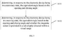
- S131 includes: determining, in response to the electronic device being in the stationary state, the equivalent angle based on a difference between the first angle of the opening and closing angle and 90 degrees.
- the opening and closing angle is the sum of the first angle and the second angle.
- the equivalent angle can be determined directly based on the display where the magnetic sensor is provided and the equivalent plane. For example, if the magnetic sensor is provided in the first sub-display, the equivalent angle is determined based on the difference between the first angle of the opening and closing angle and 90 degrees. In this way, the equivalent angle can be accurately determined so as to achieve accurate indication of the direction of the electronic device when the electronic device is in the stationary sate and the foldable screen is unfolded at a certain angle.
- S132 includes one of the following steps:
- the sub-display directed within the visual range herein is the sub-display viewed by the user.
- the first sub-display directed within the visual range is the first sub-display which is viewed by the user.
- the electronic device may include an image detection device.
- the electronic device detects image information using the image detection device, and determines, based on the image information, whether the sub-display directed within the visual range is a first sub-display or a second sub-display. In this way, in examples of the present disclosure, the sub-display viewed by the user can be determined from the images captured by the electronic device, i.e., the sub-display directed within the visual range can be determined.
- the first sub-display directed within the visual range includes the magnetic sensor, and determining the equivalent angle based on the difference between the first angle of the opening and closing angle and 90 degrees, includes one of the following steps:
- the electronic device is in the moving state. If the user is viewing the first sub-display 11, the magnetic sensor 110 is provided in the first sub-display 11, and the first sub-display 11 is parallel to the equivalent plane 20 perpendicular to the horizontal plane, then the first sub-display 11 is also perpendicular to the horizontal plane (i.e. the first angle is 90 degrees), and the equivalent angle is determined as 0 degrees (i.e. the difference between the first angle and 90 degrees).
- the direction of view of the user towards to the first sub-display can be determined to be horizontal, i.e. the direction of motion of the electronic device.
- the equivalent angle of the magnetic sensor is 0 degrees, i.e. the motion data collected by the first acceleration sensor and the directional data collected by the magnetic sensor themselves correspond to the equivalent plane, then no equivalence is necessary to achieve accurate indication of the direction of the electronic device's motion (i.e. the electronic device is moving).
- the first sub-display in response to the sub-display directed within the visual range being the first sub-display, the first sub-display including the magnetic sensor, and the first sub-display being not parallel to the equivalent plane, it can be determined that the direction in which the user looks towards the first sub-display is not horizontal, i.e. the direction is not the direction of motion of the electronic device.
- the equivalent angle of the magnetic sensor which is the difference between the first angle and 90 degrees, so that the direction in which the user looks towards the first sub-display is equivalent to the horizontal direction to achieve accurate indication of the motion direction of the electronic device.
- the electronic device is in moving state. If the user is viewing the first sub-display 11 which is parallel to the equivalent plane 20, the equivalent plane 20 is perpendicular to the horizontal plane, the magnetic sensor 110 is not provided in the first sub-display 11 but in the second sub-display 12, then the magnetic sensor needs to be equivalent to the equivalent plane 20, and the equivalent angle C is the opening and closing angle. As shown in FIG. 9 , the opening and closing angle is the difference between the first angle and the second angle.
- the magnetic sensor provided in the second sub-display in response to the magnetic sensor being not provided in the first sub-display directed within the visual range, and the first sub-display being parallel to the equivalent plane, the magnetic sensor provided in the second sub-display can be equivalent to the equivalent plane, so that the equivalent angle can be determined as the opening and closing angle, facilitating the equivalence of the motion data detected by the second acceleration sensor and the directional data detected by the magnetic sensor to the same plane, and thus realizing the accurate indication of the motion direction of the electronic device.
- FIG. 7 or FIG. 8, or FIG. 9 illustrates an example application scenario where the outer screen is directed within the visual range.
- the inner screen is directed within the visual range.
- FIG. 7 or FIG. 8, or FIG. 9 illustrates an example application scenario where the horizontal screen is directed within the visual range.
- the vertical screen is directed within the visual range.
- the equivalent angle can be determined when the electronic device is in a stationary state or a moving state; and the equivalent angle can also be determined when the electronic device is in a moving state and the sub-display directed within the visual range is provided with or without a magnetic sensor or the sub-display directed within the visual range is or is not parallel to the equivalent plane in the moving state, etc.
- the examples of the present disclosure provide a scheme for determining the equivalent angle in a variety of application scenarios, so that accurate indication of the motion direction of the electronic device in these application scenarios can be achieved.
- mapping the detected motion data to the equivalent plane and obtaining the equivalent motion data at S12 includes one of the following steps.
- mapping in response to the magnetic sensor being provided in the first sub-display directed within the visual range and the first sub-display being parallel to the equivalent plane, the motion data detected by the first acceleration sensor to the equivalent plane, and obtaining the equivalent motion data.
- the equivalent motion data can be determined by the method at S123.
- the motion data detected by both acceleration sensors can be equivalent to the equivalent plane, thereby obtaining more accurate equivalent motion data, which in tum can further improve the accuracy of indicating the direction of the electronic device.
- the equivalent angle is determined as 0 degrees, and the direction in which the user views the electronic device is the same as the direction of motion of the electronic device.
- the motion data detected by the first acceleration sensor can represent the motion of the electronic device, so that only the motion data detected by the first acceleration sensor can be equivalent to the equivalent plane, which also realizes the accurate indication of the direction of motion of the electronic device.
- FIG. 11 provides an example illustrating an apparatus for obtaining data indicating direction, applied to an electronic device.
- the electronic device includes a foldable screen with a magnetic sensor, and the apparatus includes:
- the apparatus further includes:
- the foldable screen includes at least a first sub-display and a second sub-display, the first sub-display includes a first acceleration sensor and the second sub-display includes a second acceleration sensor; and the obtaining module 43 is further configured to perform at least one of following:
- the determination module 41 is further configured to determine, in response to the electronic device being in a stationary state, the equivalent angle based on the opening and closing angle; or the determination module 41 is further configured to determine, in response to the electronic device being in a moving state, the equivalent angle based on the opening and closing angle and whether the magnetic sensor is provided in a sub-display directed within a visual range.
- the magnetic sensor is provided in the first sub-display; and the determination module 41 is further configured to determine, in response to the electronic device being in the stationary state, the equivalent angle based on a difference between the first angle of the opening and closing angle and 90 degrees.
- the determination module 41 is further configured to determine, in response to the electronic device being in the moving state and the magnetic sensor being provided in the first sub-display directed within the visual range, the equivalent angle based on the difference between the first angle of the opening and closing angle and 90 degrees; or the determination module 41 is further configured to determine, in response to the electronic device being in the moving state, and the magnetic sensor being provided in the second sub-display instead of being provided in the first sub-display directed within the visual range, the equivalent angle based on the opening and closing angle.
- the determination module 41 is further configured to determine that the equivalent angle is 0 degrees in response to the magnetic sensor being provided in the first sub-display directed within the visual range and the first sub-display being parallel to the equivalent plane.
- the processing module 42 is further configured to obtain the equivalent motion data by mapping motion data detected by the first acceleration sensor to the equivalent plane and mapping motion data detected by the second acceleration sensor to the equivalent plane; or the processing module 42 is further configured to obtain, in response to the magnetic sensor being provided in the first sub-display directed within the visual range and the first sub-display being parallel to the equivalent plane, the equivalent motion data by mapping the motion data detected by the first acceleration sensor to the equivalent plane.
- the determination module 41 is further configured to determine a plane perpendicular to a horizontal plane as the equivalent plane to which the magnetic sensor is equivalent; or the determination module 41 is further configured to determine a plane parallel to a horizontal plane as the equivalent plane to which the magnetic sensor is equivalent.
- Examples of the present disclosure further provide an electronic device, which includes:
- the memory may include various types of storage media that are non-transitory computer storage media capable of continuing to remember to store information thereon after the communication device has been powered down.
- the processor may be connected to the memory via a bus or the like for reading an executable program stored on the memory, to implement at least one of the methods, for example, as shown in FIGS. 1 , 4 , 5 and 10 .
- Examples of the present disclosure further provide a computer readable storage medium.
- the computer readable storage medium stores an executable program that, when executed by a processor, implements the method for obtaining data indicating direction described in any example of the present disclosure, e.g., at least one of the methods as shown in FIGS. 1 , 4 , 5 and 10 .
- FIG. 12 illustrates a block diagram of an electronic device 800 according to some examples.
- the electronic device 800 may be a mobile phone, a computer, a digital broadcast electronic device, a message sending and receiving device, a gaming console, a tablet device, a medical device, a fitness device, a personal digital assistant, and the like.
- the electronic device 800 may include one or more of the following components: processing component 802, memory 804, power component 806, multimedia component 808, audio component 810, and interface 812 for input/output (I/O), sensor component 814 and communication component 816.
- processing component 802 memory 804, power component 806, multimedia component 808, audio component 810, and interface 812 for input/output (I/O), sensor component 814 and communication component 816.
- the processing component 802 typically controls the overall operation of the electronic device 800, such as operations associated with display, telephone call, data communication camera operation, and recording operations.
- the processing component 802 may include one or more processors 820 to execute instructions to complete all or some of the steps of the method for obtaining data indicating direction described above.
- processing component 802 may include one or more modules that facilitate interaction between processing component 802 and other components.
- processing component 802 may include a multimedia module to facilitate interaction between multimedia component 808 and processing component 802.
- the memory 804 is configured to store various types of data to support operation at the device 800. Examples of such data include instructions for any application or method to operate on the electronic device 800, contact data, phonebook data, messages, pictures, videos, and the like.
- the memory 804 may be implemented by any type of volatile or non-volatile storage device or a combination thereof, such as static random access memory (SRAM), electrically erasable programmable read-only memory (EEPROM), erasable programmable read-only memory (EPROM), programmable read-only memory (PROM), read-only memory (ROM), and magnetic memory, flash memory Disk or CD-ROM.
- SRAM static random access memory
- EEPROM electrically erasable programmable read-only memory
- EPROM erasable programmable read-only memory
- PROM programmable read-only memory
- ROM read-only memory
- magnetic memory flash memory Disk or CD-ROM.
- the power component 806 provides power to various components of the electronic device 800.
- the power component 806 may include a power management system, one or more power supplies, and other components associated with generating, managing, and distributing power for the electronic device 800.
- the multimedia component 808 includes a screen that provides an output interface between the electronic device 800 and a user.
- the screen may include a liquid crystal display (LCD) and a touch panel (TP). If the screen includes a touch panel, the screen may be implemented as a touch screen to receive an input signal from a user.
- the touch panel includes one or more touch sensors to sense touches, swipes, and gestures on the touch panel. The touch sensors may not only sense the boundaries of the touch or swipe action, but also detect the duration and pressure associated with said touch or swipe action.
- the multimedia component 808 includes a front-facing camera and/or a rear-facing camera. The front camera and/or rear camera may receive external multimedia data when the device 800 is in an operating mode, such as a shooting mode or a video mode. Each front camera and rear camera may be a fixed optical lens system or have a focal length and optical zoom capability.
- the audio component 810 is configured to output and/or input an audio signal.
- the audio component 810 includes a microphone (MIC) configured to receive external audio signals when the electronic device 800 is in an operating mode, such as a call mode, a recording mode, and a voice recognition mode.
- the received audio signal may be further stored in memory 804 or sent via communication component 816.
- audio component 810 further includes a speaker for outputting an audio signal.
- the I/O interface 812 provides an interface between the processing component 802 and a peripheral interface module.
- the peripheral interface module may be a keypad, click wheel button, etc. These buttons may include, but are not limited to, a home button, a volume button, a start button and a lock button.
- the sensor component 814 includes one or more sensors for providing a status assessment of various aspects of the electronic device 800.
- sensor component 814 may detect the open/closed state of device 800, relative positioning of components, such as the components being a display and keypad of electronic device 800, sensor component 814 may also detect a change in position of electronic device 800 or a component of electronic device 800, the presence or absence of user contact with electronic device 800, orientation or acceleration/deceleration of the electronic device 800 and a change in temperature of the electronic device 800.
- the sensor component 814 may include a proximity sensor configured to detect the presence of a nearby object in the absence of any physical contact.
- the sensor component 814 may also include a light sensor, such as a CMOS or CCD image sensor, for use in an imaging application.
- the sensor component 814 may also include an acceleration sensor, a gyroscope sensor, a magnetic sensor, a pressure sensor, or a temperature sensor.
- the communication component 816 is configured to facilitate communication between the electronic device 800 and other devices by wired or wireless means.
- the electronic device 800 may access a wireless network based on a communication standard, such as WiFi, 2G or 3G, or a combination thereof.
- communication component 816 receives a broadcast signal or broadcast-related information from an external broadcast management system via a broadcast channel.
- the communication component 816 further includes a near-field communication (NFC) module to facilitate short-range communication.
- NFC near-field communication
- the NFC module may be implemented based on radio frequency identification (RFID) technology, infrared data association (IrDA) technology, ultra-wideband (UWB) technology, Bluetooth (BT) technology, and other technologies.
- RFID radio frequency identification
- IrDA infrared data association
- UWB ultra-wideband
- Bluetooth Bluetooth
- the electronic device 800 may be implemented by one or more application-specific integrated circuits (ASICs), digital signal processors (DSPs), digital signal processing devices (DSPDs), programmable logic devices (PLDs), field-programmable gate arrays (FPGAs), controllers, microcontrollers, microprocessors, or other electronic components for performing the methods described above.
- ASICs application-specific integrated circuits
- DSPs digital signal processors
- DSPDs digital signal processing devices
- PLDs programmable logic devices
- FPGAs field-programmable gate arrays
- controllers microcontrollers, microprocessors, or other electronic components for performing the methods described above.
- non-transitory computer readable storage medium including one or more instructions, such as a memory 804 including one or more instructions, the one or more instructions being executable by a processor 820 of the electronic device 800 to accomplish the method for obtaining data indicating direction described above.
- the non-transitory computer readable storage medium may be ROM, random access memory (RAM), CD-ROM, magnetic tape, floppy disk, and optical data storage devices, among others.
Landscapes
- Engineering & Computer Science (AREA)
- Theoretical Computer Science (AREA)
- Computer Hardware Design (AREA)
- General Engineering & Computer Science (AREA)
- Physics & Mathematics (AREA)
- Human Computer Interaction (AREA)
- General Physics & Mathematics (AREA)
- Mathematical Physics (AREA)
- Electromagnetism (AREA)
- User Interface Of Digital Computer (AREA)
Abstract
Description
- The present disclosure relates to, but is not limited to, the field of communications technology, and in particular to a method and apparatus for obtaining data indicating direction, electronic device, and storage medium.
- With the development of technology, the form of the display screens for electronic devices has also undergone great changes. Foldable screens are an emerging form for display in electronic devices. For example, when the foldable screen is folded, the electronic device can be displayed using the outer screen, and when the foldable screen is expanded, the electronic device can be displayed using the inner screen or the outer screen. For another example, foldable screens for electronic devices can be used in at least: a folded state, a half-folded state (or a half-expanded state) and an expanded state, depending on the degree of folding. Here, the half-folded state and expanded state can also be considered as non-folded state.
- The use of electronic devices with foldable screens in different forms brings many changes to the use of the electronic devices' sensors (e.g., acceleration sensors or magnetic sensors). The output of the sensor data needs to be adjusted according to the different usage forms of the electronic devices with foldable screens. For example, the magnetic sensor of an electronic device with a foldable screen does not accurately indicate the direction of the electronic device when it is used in a non-folded state.
- The present disclosure provides a method and apparatus for obtaining data indicating direction, an electronic device, and a storage medium.
- According to a first aspect of the present disclosure, there is provided a method for obtaining data indicating direction, applied to an electronic device. The electronic device includes a foldable screen with a magnetic sensor. The method for obtaining data indicating direction includes: determining, in response to the foldable screen being in a non-folded state, an equivalent plane to which the magnetic sensor is equivalent; mapping detected motion data to the equivalent plane, and obtaining equivalent motion data; and mapping directional data detected by the magnetic sensor to the equivalent plane, and obtaining equivalent directional data; where the equivalent motion data and the equivalent directional data indicate a motion direction of the electronic device.
- In some embodiments, the method further includes: obtaining an opening and closing angle of the foldable screen in the non-folded state; determining, based on the opening and closing angle, an equivalent angle of the foldable screen relative to the equivalent plane; and obtaining the equivalent motion data and the equivalent directional data further includes obtaining the equivalent motion data by mapping the motion data to the equivalent plane based on the equivalent angle; and obtaining the equivalent directional data by mapping the directional data to the equivalent plane based on the equivalent angle.
- In some embodiments, the foldable screen includes at least: a first sub-display and a second sub-display, the first sub-display includes a first acceleration sensor, and the second sub-display includes a second acceleration sensor; and obtaining the opening and closing angle of the foldable screen in the non-folded state further includes at least one of following acts: obtaining, based on the first acceleration sensor, a first angle between the first sub-display and a horizontal plane; obtaining, based on the second acceleration sensor, a second angle between the second sub-display and the horizontal plane; or obtaining, based on the first angle and the second angle, the opening and closing angle of the foldable screen.
- In some embodiments, determining, based on the opening and closing angle, the equivalent angle of the foldable screen relative to the equivalent plane further includes: determining, in response to the electronic device being in a stationary state, the equivalent angle based on the opening and closing angle; and determining, in response to the electronic device being in a moving state, the equivalent angle based on the opening and closing angle and whether the magnetic sensor is provided in a sub-display directed within a visual range.
- In some embodiments, the magnetic sensor is provided in the first sub-display and the method further includes determining, in response to the electronic device being in the stationary state, the equivalent angle based on a difference between the first angle of the opening and closing angle and 90 degrees.
- In some embodiments, the method further includes: determining, in response to the electronic device being in the moving state and the magnetic sensor being provided in the first sub-display directed within the visual range, the equivalent angle based on the difference between the first angle of the opening and closing angle and 90 degrees; and determining, in response to the electronic device being in the moving state, and the magnetic sensor being provided in the second sub-display instead of being provided in the first sub-display directed within the visual range, the equivalent angle based on the opening and closing angle.
- In some embodiments, the method further includes: determining that the equivalent angle is 0 degrees in response to the magnetic sensor being provided in the first sub-display directed within the visual range and the first sub-display being parallel to the equivalent plane.
- In some embodiments, obtaining the equivalent motion data by mapping the motion data to the equivalent plane further includes obtaining the equivalent motion data by mapping motion data detected by the first acceleration sensor to the equivalent plane and mapping motion data detected by the second acceleration sensor to the equivalent plane; and obtaining, in response to the magnetic sensor being provided in the first sub-display directed within the visual range and the first sub-display being parallel to the equivalent plane, the equivalent motion data by mapping the motion data detected by the first acceleration sensor to the equivalent plane.
- In some embodiments, determining the equivalent plane to which the magnetic sensor is equivalent further includes determining a plane perpendicular to a horizontal plane as the equivalent plane to which the magnetic sensor is equivalent; or determining a plane parallel to a horizontal plane as the equivalent plane to which the magnetic sensor is equivalent.
- According to a second aspect of the present disclosure, there is provided an apparatus for obtaining data indicating direction, applied to an electronic device. The electronic device includes: a foldable screen with a magnetic sensor. The apparatus for obtaining data indicating direction includes a determination module, configured to determine, in response to the foldable screen being in a non-folded state, an equivalent plane to which the magnetic sensor is equivalent; and a processing module, configured to obtain equivalent motion data by mapping motion data detected by the electronic to the equivalent plane; and obtain equivalent directional data by mapping directional data detected by the magnetic sensor to the equivalent plane. The equivalent motion data and the equivalent directional data indicate a motion direction of the electronic device.
- In some embodiments, the apparatus further includes: an obtaining module, configured to obtain an opening and closing angle of the foldable screen in the non-folded state. The determination module is further configured to determine, based on the opening and closing angle, an equivalent angle of the foldable screen relative to the equivalent plane; and the processing module is further configured to obtain the equivalent motion data by mapping the detected motion data to the equivalent plane based on the equivalent angle, and obtain the equivalent directional data by mapping the directional data detected by the magnetic sensor to the equivalent plane based on the equivalent angle.
- In some embodiments, the foldable screen includes at least: a first sub-display and a second sub-display, the first sub-display includes a first acceleration sensor and the second sub-display includes a second acceleration sensor; and the obtaining module is further configured to perform at least one of following acts: obtaining, based on the first acceleration sensor, a first angle between the first sub-display and a horizontal plane; obtaining, based on the second acceleration sensor, a second angle between the second sub-display and the horizontal plane; or obtaining, based on the first angle and the second angle, the opening and closing angle of the foldable screen.
- In some embodiments, the determination module is further configured to determine, in response to the electronic device being in a stationary state, the equivalent angle based on the opening and closing angle; or the determination module is further configured to determine, in response to the electronic device being in a moving state, the equivalent angle based on the opening and closing angle and whether the magnetic sensor is provided in a sub-display directed within a visual range.
- In some embodiments, the magnetic sensor is provided in the first sub-display; and the determination module is further configured to determine, in response to the electronic device being in the stationary state, the equivalent angle based on a difference between the first angle of the opening and closing angle and 90 degrees.
- In some embodiments, the determination module is further configured to determine, in response to the electronic device being in the moving state and the magnetic sensor being provided in the first sub-display directed within the visual range, the equivalent angle based on the difference between the first angle of the opening and closing angle and 90 degrees; or the determination module is further configured to determine, in response to the electronic device being in the moving state, and the magnetic sensor being provided in the second sub-display instead of being provided in the first sub-display directed within the visual range, the equivalent angle based on the opening and closing angle.
- In some embodiments, the determination module is further configured to determine that the equivalent angle is 0 degrees in response to the magnetic sensor being provided in the first sub-display directed within the visual range and the first sub-display being parallel to the equivalent plane.
- In some embodiments, the processing module is further configured to obtain the equivalent motion data by mapping motion data detected by the first acceleration sensor to the equivalent plane and mapping motion data detected by the second acceleration sensor to the equivalent plane; and the processing module is further configured to obtain, in response to the magnetic sensor being provided in the first sub-display directed within the visual range and the first sub-display being parallel to the equivalent plane, the equivalent motion data by mapping the motion data detected by the first acceleration sensor to the equivalent plane.
- In some embodiments, the determination module is further configured to determine a plane perpendicular to a horizontal plane as the equivalent plane to which the magnetic sensor is equivalent; or the determination module is further configured to determine a plane parallel to a horizontal plane as the equivalent plane to which the magnetic sensor is equivalent.
- According to a third aspect of the present disclosure, there is provided an electronic device, including: a foldable screen with a magnetic sensor; a processor; and a memory configured to store one or more executable instructions for the processor. The processor is configured to implement, when running the one or more executable instructions, the method for obtaining data indicating direction described in the first aspect of the present disclosure.
- According to a fourth aspect of the present disclosure, there is provided a non-transitory computer readable storage medium storing an executable program. The executable program implements, when executed by a processor, the method for obtaining data indicating direction described in the first aspect of the present disclosure.
- In the embodiments of the present disclosure, in response to the foldable screen being in a non-folded state, the equivalent plane to which the magnetic sensor is equivalent is determined; the equivalent motion data is obtained by mapping the detected motion data to the equivalent plane, and the equivalent directional data is obtained by mapping directional data detected by the magnetic sensor to the equivalent plane. The equivalent motion data and the equivalent directional data are used for indicating a motion direction of the electronic device. Thus, by the method described in the embodiments of the present disclosure, the electronic device, with the foldable screen in the non-folded state, can equate both the detected motion data and the directional data detected by the magnetic sensor to the equivalent plane to which the magnetic sensor needs to be equivalent, so that the equivalent motion data after the equivalent can compensate for the tilt of the acceleration sensor. This allows the foldable screen, even when unfolded at a certain angle, to enable the magnetic sensor to accurately determine the motion direction of the electronic device.
- It should be understood that the above general description and the following detailed description are exemplary and explanatory only and cannot limit the present disclosure. The scope of the invention is defined by the claims.
- The accompanying drawings herein are incorporated into and form part of this description, illustrate embodiments consistent with this disclosure, and are used with the description to explain the principles of this disclosure.
-
FIG. 1 illustrates a flowchart of a method for obtaining data indicating direction according to one or more examples of the present disclosure. -
FIG. 2 illustrates a schematic diagram of a foldable screen according to one or more examples of the present disclosure. -
FIG. 3 illustrates a schematic diagram of a foldable screen according to one or more examples of the present disclosure. -
FIG. 4 illustrates a flowchart of a method for obtaining data indicating direction according to one or more examples of the present disclosure. -
FIG. 5 illustrates a flowchart of a method for obtaining data indicating direction according to one or more examples of the present disclosure. -
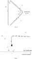
FIG. 6 illustrates a schematic diagram of a foldable screen according to one or more examples of the present disclosure. -
FIG. 7 illustrates a schematic diagram of a foldable screen according to one or more examples of the present disclosure. -
FIG. 8 illustrates a schematic diagram of a foldable screen according to one or more examples of the present disclosure. -
FIG. 9 illustrates a schematic diagram of a foldable screen according to one or more examples of the present disclosure. -
FIG. 10 illustrates a flowchart of a method for obtaining data indicating direction according to one or more examples of the present disclosure. -
FIG, 11 illustrates a block diagram of a method for obtaining data indicating direction according to one or more examples of the present disclosure. -
FIG. 12 illustrates a block diagram of an electronic device according to one or more examples of the present disclosure. - Reference will now be described in detail to examples, which are illustrated in the accompanying drawings. The following description refers to the accompanying drawings in which the same numbers in different drawings represent the same or similar elements unless otherwise represented. The examples described below do not represent all examples consistent with the present disclosure. Instead, they are merely examples of devices and methods consistent with aspects of the disclosure as defined by the appended claims.
- Terms used in the present disclosure are merely for describing specific examples and are not intended to limit the present disclosure. The singular forms "one", "the", and "this" used in the present disclosure and the appended claims are also intended to include a multiple form, unless other meanings are clearly represented in the context. It should also be understood that the term "and/or" used in the present disclosure refers to any or all of possible combinations including one or more associated listed items.
- Reference throughout this specification to "one embodiment," "an embodiment," "an example," "some embodiments," "some examples," or similar language means that a particular feature, structure, or characteristic described is included in at least one embodiment or example. Features, structures, elements, or characteristics described in connection with one or some embodiments are also applicable to other embodiments, unless expressly specified otherwise.
- It should be understood that although terms "first", "second", "third", and the like are used in the present disclosure to describe various information, the information is not limited to the terms. These terms are merely used to differentiate information of a same type. For example, without departing from the scope of the present disclosure, first information is also referred to as second information, and similarly the second information is also referred to as the first information. Depending on the context, for example, the term "if' used herein may be explained as "when" or "while", or "in response to ..., it is determined that".
- The terms "module," "sub-module," "circuit," "sub-circuit," "circuitry," "sub-circuitry," "unit," or "sub-unit" may include memory (shared, dedicated, or group) that stores code or instructions that can be executed by one or more processors. A module may include one or more circuits with or without stored code or instructions. The module or circuit may include one or more components that are directly or indirectly connected. These components may or may not be physically attached to, or located adjacent to, one another.
- A unit or module may be implemented purely by software, purely by hardware, or by a combination of hardware and software. In a pure software implementation, for example, the unit or module may include functionally related code blocks or software components, that are directly or indirectly linked together, so as to perform a particular function.
-
FIG. 1 illustrates a flowchart of a method for obtaining data indicating direction provided in examples of the present disclosure. As shown inFIG. 1 , the method for obtaining data indicating direction is applied to an electronic device including a foldable screen with a magnetic sensor, and the method includes the following steps. - At S11, determining, in response to the foldable screen being in a non-folded state, an equivalent plane to which the magnetic sensor is equivalent.
- At S12, mapping detected motion data to the equivalent plane, and obtaining equivalent motion data; and mapping directional data detected by the magnetic sensor to the equivalent plane, and obtaining equivalent directional data.
- The equivalent motion data and the equivalent directional data are used for indicating a motion direction of the electronic device.
- The method for obtaining data indicating direction, described in examples of the present disclosure, is applied to an electronic device, and the electronic device includes a foldable screen. The electronic device herein is a mobile terminal or fixed terminal of any kind. For example, the electronic device may be, but is not limited to, a mobile phone, a computer, a tablet, or a television, and the like.
- Here, the foldable screen includes at least two sub-displays.
- In some examples, the foldable screen includes a first sub-display and a second sub-display.
- In some examples, the first sub-display includes the magnetic sensor; alternatively, the second sub-display includes the magnetic sensor. For example, as shown in
FIG. 2 , there is amagnetic sensor 110 built into thefirst sub-display 11. In some examples, the magnetic sensor may be considered a compass. - Of course, in other examples, the magnetic sensor may be replaced with magnetic components that are capable of detecting the directional data used for indicating the direction of the electronic device, without limitation herein.
- In some examples, the magnetic sensor is a three-axis magnetic sensor. The three axes of the three-axis magnetic sensor may include an X-axis, a Y-axis and a Z-axis. The X and Y axes here are two components indicating a plane parallel to the horizontal plane, the X and Y axes are perpendicular to each other and the Z axis is used for indicating a component perpendicular to the horizontal plane. Of course, in other examples, the magnetic sensor may be any other type of magnetic sensor or magnetic component, without limitation herein.
- In some examples, the foldable screen includes one or more acceleration sensors.
- S12 includes: mapping motion data detected by the one or more acceleration sensors to the equivalent plane, and obtaining the equivalent motion data; and mapping directional data detected by the magnetic sensor to the equivalent plane, and obtaining the equivalent directional data.
- The equivalent motion data, together with the equivalent directional data, is used for indicating the motion direction of the electronic device by the magnetic sensor which is equivalent to the equivalent plane.
- In this way, in examples of the present disclosure, the acceleration sensor(s) and the magnetic sensor of the electronic device can be equivalent to the same plane, such that the acceleration sensor(s) can compensate for tilt angle of the magnetic sensor to achieve accurate positioning of the electronic device even if the foldable screen of the electronic device is in a non-folded state.
- In some examples, the one or more acceleration sensors include a first acceleration sensor and a second acceleration sensor, and the first acceleration sensor is provided in the first sub-display and the second acceleration sensor is provided in the second sub-display. For example, as shown in
FIG. 2 , afirst acceleration sensor 111 is built into thefirst sub-display 11, and asecond acceleration sensor 121 is built into thesecond sub-display 12. - Of course, in other examples, the acceleration sensor may be replaced with motion detection components that are capable of detecting the motion data used for indicating the velocity and acceleration of the electronic device, without limitation herein.
- In some examples, the acceleration sensor is a three-axis acceleration sensor. The three axes of the three-axis acceleration sensor may include an X-axis, a Y-axis and a Z-axis. The X and Y axes here are two components indicating a plane parallel to the horizontal plane, the X and Y axes are perpendicular to each other and the Z axis is used for indicating a component perpendicular to the horizontal plane. Of course, in other examples, the acceleration sensor may be any other type of acceleration sensor or motion detection component, without limitation herein.
- In some examples, the first acceleration sensor and the second acceleration sensor may be provided symmetrically based on a folding line of the foldable screen. Of course, in other examples, the first acceleration sensor and the second acceleration sensor may also be provided symmetrically without being based on the folding line of the foldable screen.
- The foldable screen herein may be in a folded state or a non-folded state. The non-folded state includes a half-expanded state and an expanded state. For example, in some examples, when the foldable screen is in the folded state, an angle between the first sub-display and the second sub-display is 0 degrees; when the foldable screen is in the half-expanded state, the angle between the first sub-display and the second sub-display is greater than 0 degrees and less than 180 degrees; and when the foldable screen is in the expanded state, the angle between the first sub-display and the second sub-display is 180 degrees. The half-expanded state herein may also be considered as a half-folded state.
- In some examples, the non-folded state of the foldable screen may include: an expanded state, a half-folded state where the foldable screen is folded outwardly, or a half-folded state where the foldable screen is folded inwardly. For example, as shown in
FIG. 3 , when the foldable screen is in a half-folded state folded outwardly, content may be displayed on anouter screen 21 of the foldable screen, and when the foldable screen is in a half-folded state folded inwardly, content may be displayed on aninner screen 22 of the foldable screen. - In some examples, the non-folded state of the foldable screen may include: a non-folded state with the foldable screen being in landscape orientation, or a non-folded state with the foldable screen being in portrait orientation.
- The motion data detected by the acceleration sensors herein, which may include motion data detected by the first sensor at the first sub-display and/or motion data detected by the second sensor at the second sub-display. The motion data includes data on the velocity and/or acceleration of the motion of the foldable screen.
- The directional data detected by the magnetic sensor herein, which may include: directional data detected by the magnetic sensor at the first sub-display, or directional data detected by the magnetic sensor at the second sub-display.
- In some examples, the equivalent plane includes, but not limited to, at least one of: a plane perpendicular to the horizontal plane, and a plane parallel to the horizontal plane.
- In some examples, the determining the equivalent plane to which the magnetic sensor is equivalent, includes:
- determining the plane perpendicular to the horizontal plane as the equivalent plane to which the magnetic sensor is equivalent; or
- determining the plane parallel to the horizontal plane as the equivalent plane to which the magnetic sensor is equivalent.
- In some examples, if the foldable screen is in the non-folded state, the plane parallel to the horizontal plane is set by default to be the equivalent plane. In another example, if the foldable screen is in the non-folded state, the plane perpendicular to the horizontal plane is set by default to be the equivalent plane.
- Referring again to
FIG. 2 , when the magnetic sensor is equivalent to the equivalent plane, the equivalent magnetic sensor may be at any position in the equivalent plane; for example, it may be atposition 10 of the equivalent plane. - In this way, in this example, the magnetic sensor can be equivalent to a horizontal plane or a plane perpendicular to the horizontal plane. Thus, the equivalent magnetic sensor on the horizontal plane or the plane perpendicular to the horizontal plane can be considered as not tilted or tilted by 90 degrees, thereby enabling the equivalent magnetic sensor to achieve more accurate direction indication.
- Of course, in other examples, the equivalent plane may also be any of the planes. In this way, in this example, accurate indication of the direction of the electronic device is achieved by simply allowing the data detected by the acceleration sensor to correspond to the same plane as the data detected by the magnetic sensor, so that the acceleration sensor can compensate for the tilt angle of the magnetic sensor as well.
- In some examples, the direction of motion of the electronic device includes: the direction of motion of the electronic device when it is stationary or the direction of motion of the electronic device when it is moving. For example, the electronic device is statically placed on a table, such as being in a direction due north. Another example is when the electronic device is moving forward, such as in a direction 30 degrees southeast, or in a direction in which the electronic device is moving backward, to the left or right, or to the right.
- In the examples of the present disclosure, equivalent plane to which the magnetic sensor is equivalent may be determined in response to the foldable screen of the electronic device being in the non-folded state; the equivalent motion data is obtained by mapping the detected motion data to the equivalent plane; and the equivalent directional data is obtained by mapping the directional data detected by the magnetic sensor to the equivalent plane. The equivalent motion data and the equivalent directional data are used for indicating the motion direction of the electronic device. In this way, with the method described in the example of the present disclosure, the electronic device with the foldable screen in the non-folded state can make the detected motion data and the directional data detected by the magnetic sensor both equivalent to the equivalent plane to which the magnetic sensor needs to be equivalent, so that the equivalent motion data after equivalence can compensate for the tilt of the acceleration sensor. Thus, the magnetic sensor can accurately determine the motion direction of the electronic device, even when the foldable screen is unfolded at a certain angle.
- As shown in
FIG. 4 , in some examples, the method for obtaining data indicating direction further includes the following steps. - At S10, obtaining an opening and closing angle of the foldable screen in the non-folded state.
- At S13, determining, based on the opening and closing angle, an equivalent angle of the foldable screen relative to the equivalent plane.
- S12 includes the following steps.
- At S121, mapping, based on the equivalent angle, the detected motion data to the equivalent plane, and obtaining the equivalent motion data.
- At S122, mapping, based on the equivalent angle, the directional data detected by the magnetic sensor to the equivalent plane, and obtaining the equivalent directional data.
- The foldable screen herein includes a first sub-display and a second sub-display, the first sub-display includes a first acceleration sensor and the second sub-display includes a second acceleration sensor.
- The opening and closing angle of the foldable screen in the non-folded state here is the angle between the first sub-display and the second sub-display.
- In some examples, S121 includes mapping, based on the equivalent angle, the motion data detected by the acceleration sensor to the equivalent plane, and obtaining the equivalent motion data.
- A manner of achieving S121 is to convert the motion data detected by the acceleration sensor in a first coordinate system to a second coordinate system differing by an equivalent angle from the first coordinate system to obtain the equivalent motion data in the second coordinate system.
- In some examples, if the detected motion data is data with components on the X, Y and Z axes, which are VX1, Vy1, and Vz1 respectively, the foldable screen is a vertical screen in the non-folded state at the equivalent angle C, then the equivalent motion data has components on the X, Y and Z axes, which are VX2= cosC×VX1, Vy2= sinC×Vy1, Vz2=Vz1 respectively, and the equivalent motion data relative to the equivalent plane are obtained based on VX2, Vy2, and Vz2.
- A manner of achieving S122 is to convert the directional data detected by the magnetic sensor in a first coordinate system to a second coordinate system differing by an equivalent angle from the first coordinate system to obtain the equivalent directional data in the second coordinate system.
- In some examples, if the directional data detected by the acceleration sensor is data with components on the X, Y and Z axes, which are LX1, Ly1, and Lz1 respectively, the foldable screen is a vertical screen in the non-folded state at the equivalent angle C, then the equivalent motion data has components on the X, Y and Z axes, which are LX2= cosC×LX1, Ly2= sinC×Ly1, Lz2=Lz1, and the equivalent motion data relative to the equivalent plane are obtained based on LX2, Ly2, and Lz2.
- Of course, in other examples, there may be any of the other achievable equivalent manners, as long as the equivalence for the motion data and directional data is realized based on the same principle, which is not limited herein.
- In some examples, S13 may include: determining the equivalent angle based on the opening and closing angle and the equivalent plane. Here, the equivalent angle is an angle between the sub-display provided with the magnetic sensor and the equivalent plane.
- In some examples, S13 includes at least one of the following steps:
- obtaining, based on the first acceleration sensor, a first angle between the first sub-display and a horizontal plane;
- obtaining, based on the second acceleration sensor, a second angle between the second sub-display and the horizontal plane;
- obtaining, based on the first angle and the second angle, the opening and closing angle of the foldable screen.
- In some examples, obtaining the opening and closing angle of the foldable screen based on the first angle and the second angle, includes: obtaining the opening and closing angle of the foldable screen based on a sum of the first angle and the second angle.
- In another example, obtaining the opening and closing angle of the foldable screen based on the first angle and the second angle, includes: obtaining the opening and closing angle of the foldable screen based on a difference between the first angle and the second angle.
- In some examples, determining the equivalent angle based on the opening and closing angle, includes, but is limited to, at least one of the following:
- determining the equivalent angle based on the opening and closing angle;
- determining, based on the first angle of the opening and closing angle, the equivalent angle in response to the magnetic sensor being in the first sub-display;
- determining, based on the second angle of the opening and closing angle, the equivalent angle in response to the magnetic sensor being in the second sub-display.
- In the examples of the present disclosure, the opening and closing angle of the foldable screen can be obtained based on the non-foldable state held by the foldable screen, and based on the opening and closing angle, the equivalent angle of the magnetic sensor equivalent to the equivalent plane can be determined. In this way, accurate equivalence of motion data and directional data based on the equivalent angle can be achieved in the examples of the present disclosure, so that the equivalent directional data and equivalent motion data after equivalence can be used to determine the direction of the electronic device accurately.
- As shown in
FIG. 5 , in some examples, S13 includes at least one of the following steps. - At S131, determining, in response to the electronic device being in a stationary state, the equivalent angle based on the opening and closing angle.
- At S132, determining, in response to the electronic device being in a moving state, the equivalent angle based on the opening and closing angle and whether the magnetic sensor is provided in a sub-display directed within a visual range.
- In some examples, the magnetic sensor is provided in the first sub-display.
- S131 includes: determining, in response to the electronic device being in the stationary state, the equivalent angle based on a difference between the first angle of the opening and closing angle and 90 degrees.
- In some examples, as shown in
FIG. 6 , assuming that the electronic device is in the stationary state, the first angle between thefirst sub-display 11 and the horizontal plane is denoted as A, the second angle between thesecond sub-display 12 and the horizontal plane is denoted as B, and theequivalent plane 20 is a plane perpendicular to the horizontal plane, the equivalent angle C can be determined based on the first angle A of the opening and closing angle, i.e., C=90°-A. InFIG. 6 , the opening and closing angle is the sum of the first angle and the second angle. - In the above example, if the magnetic sensor is provided in the second sub-display, then the equivalent angle C=90°-B.
- In the examples of the present disclosure, if the electronic device is in the stationary state, it is not possible to determine the sub-display viewed by the user. The equivalent angle can be determined directly based on the display where the magnetic sensor is provided and the equivalent plane. For example, if the magnetic sensor is provided in the first sub-display, the equivalent angle is determined based on the difference between the first angle of the opening and closing angle and 90 degrees. In this way, the equivalent angle can be accurately determined so as to achieve accurate indication of the direction of the electronic device when the electronic device is in the stationary sate and the foldable screen is unfolded at a certain angle.
- In some examples, S132 includes one of the following steps:
- determining, in response to the electronic device being in the moving state and the magnetic sensor being provided in the first sub-display directed within the visual range, the equivalent angle based on the difference between the first angle of the opening and closing angle and 90 degrees;
- determining, in response to the electronic device being in the moving state, and the magnetic sensor being provided in the second sub-display instead of being provided in the first sub-display directed within the visual range, the equivalent angle based on the opening and closing angle.
- The sub-display directed within the visual range herein is the sub-display viewed by the user. For example, the first sub-display directed within the visual range is the first sub-display which is viewed by the user.
- In some examples, the electronic device may include an image detection device. In some examples, the electronic device detects image information using the image detection device, and determines, based on the image information, whether the sub-display directed within the visual range is a first sub-display or a second sub-display. In this way, in examples of the present disclosure, the sub-display viewed by the user can be determined from the images captured by the electronic device, i.e., the sub-display directed within the visual range can be determined.
- In some examples, the first sub-display directed within the visual range includes the magnetic sensor, and determining the equivalent angle based on the difference between the first angle of the opening and closing angle and 90 degrees, includes one of the following steps:
- determining that the equivalent angle is 0 degrees in response to the magnetic sensor being provided in the first sub-display directed within the visual range and the first sub-display being parallel to the equivalent plane;
- determining that the equivalent angle is the difference between the first angle and 90 degrees in response to the magnetic sensor being provided in the first sub-display directed within the visual range and the first sub-display being not parallel to the equivalent plane.
- In some examples, as shown in
FIG. 7 , the electronic device is in the moving state. If the user is viewing thefirst sub-display 11, themagnetic sensor 110 is provided in thefirst sub-display 11, and thefirst sub-display 11 is parallel to theequivalent plane 20 perpendicular to the horizontal plane, then thefirst sub-display 11 is also perpendicular to the horizontal plane (i.e. the first angle is 90 degrees), and the equivalent angle is determined as 0 degrees (i.e. the difference between the first angle and 90 degrees). - In this way, in the examples of the present disclosure, in response to the sub-display directed within the visual range (i.e. the sub-display viewed by the user) being the first sub-display and the first sub-display including a magnetic sensor, and the first sub-display being parallel to the equivalent plane, the direction of view of the user towards to the first sub-display can be determined to be horizontal, i.e. the direction of motion of the electronic device. In this way, it can be determined that the equivalent angle of the magnetic sensor is 0 degrees, i.e. the motion data collected by the first acceleration sensor and the directional data collected by the magnetic sensor themselves correspond to the equivalent plane, then no equivalence is necessary to achieve accurate indication of the direction of the electronic device's motion (i.e. the electronic device is moving).
- In some examples, as shown in
FIG. 8 , the electronic device is in the moving state. If the user is viewing thefirst sub-display 11, themagnetic sensor 110 is provided in thefirst sub-display 11, thefirst sub-display 11 is not parallel to theequivalent plane 20, there is an angle between thefirst sub-display 11 and the horizontal plane denoted as a first angle A, and theequivalent plane 20 is perpendicular to the horizontal plane, then the equivalent angle C=90°-A. - In this way, in the examples of the present disclosure, in response to the sub-display directed within the visual range being the first sub-display, the first sub-display including the magnetic sensor, and the first sub-display being not parallel to the equivalent plane, it can be determined that the direction in which the user looks towards the first sub-display is not horizontal, i.e. the direction is not the direction of motion of the electronic device. In this way, it is necessary to determine the equivalent angle of the magnetic sensor which is the difference between the first angle and 90 degrees, so that the direction in which the user looks towards the first sub-display is equivalent to the horizontal direction to achieve accurate indication of the motion direction of the electronic device.
- In some examples, as shown in
FIG. 9 , the electronic device is in moving state. If the user is viewing thefirst sub-display 11 which is parallel to theequivalent plane 20, theequivalent plane 20 is perpendicular to the horizontal plane, themagnetic sensor 110 is not provided in thefirst sub-display 11 but in thesecond sub-display 12, then the magnetic sensor needs to be equivalent to theequivalent plane 20, and the equivalent angle C is the opening and closing angle. As shown inFIG. 9 , the opening and closing angle is the difference between the first angle and the second angle. - In this way, in the examples of the present disclosure, in response to the magnetic sensor being not provided in the first sub-display directed within the visual range, and the first sub-display being parallel to the equivalent plane, the magnetic sensor provided in the second sub-display can be equivalent to the equivalent plane, so that the equivalent angle can be determined as the opening and closing angle, facilitating the equivalence of the motion data detected by the second acceleration sensor and the directional data detected by the magnetic sensor to the same plane, and thus realizing the accurate indication of the motion direction of the electronic device.
-
FIG. 7 orFIG. 8, or FIG. 9 , illustrates an example application scenario where the outer screen is directed within the visual range. Of course, in other examples, it may also be an application scenario where the inner screen is directed within the visual range. -
FIG. 7 orFIG. 8, or FIG. 9 , illustrates an example application scenario where the horizontal screen is directed within the visual range. Of course, in other examples, it may also be an application scenario where the vertical screen is directed within the visual range. - In examples of the present disclosure, the equivalent angle can be determined when the electronic device is in a stationary state or a moving state; and the equivalent angle can also be determined when the electronic device is in a moving state and the sub-display directed within the visual range is provided with or without a magnetic sensor or the sub-display directed within the visual range is or is not parallel to the equivalent plane in the moving state, etc. Thus, the examples of the present disclosure provide a scheme for determining the equivalent angle in a variety of application scenarios, so that accurate indication of the motion direction of the electronic device in these application scenarios can be achieved.
- As shown in
FIG. 10 , in some examples, mapping the detected motion data to the equivalent plane and obtaining the equivalent motion data at S12, includes one of the following steps. - At S123, mapping motion data detected by the first acceleration sensor to the equivalent plane and mapping motion data detected by the second acceleration sensor to the equivalent plane, and obtaining the equivalent motion data.
- At S124, mapping, in response to the magnetic sensor being provided in the first sub-display directed within the visual range and the first sub-display being parallel to the equivalent plane, the motion data detected by the first acceleration sensor to the equivalent plane, and obtaining the equivalent motion data.
- In any of the above examples, the equivalent motion data can be determined by the method at S123. In this way, the motion data detected by both acceleration sensors can be equivalent to the equivalent plane, thereby obtaining more accurate equivalent motion data, which in tum can further improve the accuracy of indicating the direction of the electronic device.
- In the examples of the present disclosure, in response to the first sub-display directed within the visual range being provided with the magnetic sensor, and the first sub-display being parallel to the equivalent plane, the equivalent angle is determined as 0 degrees, and the direction in which the user views the electronic device is the same as the direction of motion of the electronic device. In this way, the motion data detected by the first acceleration sensor can represent the motion of the electronic device, so that only the motion data detected by the first acceleration sensor can be equivalent to the equivalent plane, which also realizes the accurate indication of the direction of motion of the electronic device.
-
FIG. 11 provides an example illustrating an apparatus for obtaining data indicating direction, applied to an electronic device. The electronic device includes a foldable screen with a magnetic sensor, and the apparatus includes: - a
determination module 41, configured to determine, in response to the foldable screen being in a non-folded state, an equivalent plane to which the magnetic sensor is equivalent; and - a
processing module 42, configured to obtain equivalent motion data by mapping motion data detected by the electronic device to the equivalent plane; and obtain equivalent directional data by mapping directional data detected by the magnetic sensor to the equivalent plane; - where the equivalent motion data and the equivalent directional data are used for indicating a motion direction of the electronic device.
- In some examples, the apparatus further includes:
- an obtaining
module 43, configured to obtain an opening and closing angle of the foldable screen in the non-folded state; - the
determination module 41 is further configured to determine, based on the opening and closing angle, an equivalent angle of the foldable screen relative to the equivalent plane; and - the
processing module 42 is further configured to obtain the equivalent motion data by mapping the detected motion data to the equivalent plane based on the equivalent angle, and obtain the equivalent directional data by mapping the directional data detected by the magnetic sensor to the equivalent plane based on the equivalent angle. - In some examples, the foldable screen includes at least a first sub-display and a second sub-display, the first sub-display includes a first acceleration sensor and the second sub-display includes a second acceleration sensor; and
the obtainingmodule 43 is further configured to perform at least one of following: - obtaining, based on the first acceleration sensor, a first angle between the first sub-display and a horizontal plane;
- obtaining, based on the second acceleration sensor, a second angle between the second sub-display and the horizontal plane;
- obtaining, based on the first angle and the second angle, the opening and closing angle of the foldable screen.
- In some example, the
determination module 41 is further configured to determine, in response to the electronic device being in a stationary state, the equivalent angle based on the opening and closing angle; or
thedetermination module 41 is further configured to determine, in response to the electronic device being in a moving state, the equivalent angle based on the opening and closing angle and whether the magnetic sensor is provided in a sub-display directed within a visual range. - In some examples, the magnetic sensor is provided in the first sub-display; and
thedetermination module 41 is further configured to determine, in response to the electronic device being in the stationary state, the equivalent angle based on a difference between the first angle of the opening and closing angle and 90 degrees. - In some examples, the
determination module 41 is further configured to determine, in response to the electronic device being in the moving state and the magnetic sensor being provided in the first sub-display directed within the visual range, the equivalent angle based on the difference between the first angle of the opening and closing angle and 90 degrees; or
thedetermination module 41 is further configured to determine, in response to the electronic device being in the moving state, and the magnetic sensor being provided in the second sub-display instead of being provided in the first sub-display directed within the visual range, the equivalent angle based on the opening and closing angle. - In some examples, the
determination module 41 is further configured to determine that the equivalent angle is 0 degrees in response to the magnetic sensor being provided in the first sub-display directed within the visual range and the first sub-display being parallel to the equivalent plane. - In some examples, the
processing module 42 is further configured to obtain the equivalent motion data by mapping motion data detected by the first acceleration sensor to the equivalent plane and mapping motion data detected by the second acceleration sensor to the equivalent plane; or
theprocessing module 42 is further configured to obtain, in response to the magnetic sensor being provided in the first sub-display directed within the visual range and the first sub-display being parallel to the equivalent plane, the equivalent motion data by mapping the motion data detected by the first acceleration sensor to the equivalent plane. - In some example, the
determination module 41 is further configured to determine a plane perpendicular to a horizontal plane as the equivalent plane to which the magnetic sensor is equivalent; or
thedetermination module 41 is further configured to determine a plane parallel to a horizontal plane as the equivalent plane to which the magnetic sensor is equivalent. - With respect to the apparatus in the above-described examples, the specific manner in which the individual modules perform operations has been described in detail in the examples relating to the method for obtaining data indicating direction, and will not be described in detail here.
- Examples of the present disclosure further provide an electronic device, which includes:
- a processor; and
- a memory configured to store one or more executable instructions for the processor;
- where the processor is configured to implement, when running the one or more executable instructions thereon, the method for obtaining data indicating direction described in any example of the present disclosure.
- The memory may include various types of storage media that are non-transitory computer storage media capable of continuing to remember to store information thereon after the communication device has been powered down.
- The processor may be connected to the memory via a bus or the like for reading an executable program stored on the memory, to implement at least one of the methods, for example, as shown in
FIGS. 1 ,4 ,5 and10 . - Examples of the present disclosure further provide a computer readable storage medium. The computer readable storage medium stores an executable program that, when executed by a processor, implements the method for obtaining data indicating direction described in any example of the present disclosure, e.g., at least one of the methods as shown in
FIGS. 1 ,4 ,5 and10 . - With respect to the apparatus described in the above examples, the specific manner in which the individual modules perform operations has been described in detail in the examples relating to the method for obtaining data indicating direction, and will not be described in detail here.
-
FIG. 12 illustrates a block diagram of anelectronic device 800 according to some examples. For example, theelectronic device 800 may be a mobile phone, a computer, a digital broadcast electronic device, a message sending and receiving device, a gaming console, a tablet device, a medical device, a fitness device, a personal digital assistant, and the like. - Referring to
FIG. 12 , theelectronic device 800 may include one or more of the following components: processingcomponent 802,memory 804,power component 806,multimedia component 808,audio component 810, andinterface 812 for input/output (I/O),sensor component 814 andcommunication component 816. - The
processing component 802 typically controls the overall operation of theelectronic device 800, such as operations associated with display, telephone call, data communication camera operation, and recording operations. Theprocessing component 802 may include one ormore processors 820 to execute instructions to complete all or some of the steps of the method for obtaining data indicating direction described above. In addition,processing component 802 may include one or more modules that facilitate interaction betweenprocessing component 802 and other components. For example,processing component 802 may include a multimedia module to facilitate interaction betweenmultimedia component 808 andprocessing component 802. - The
memory 804 is configured to store various types of data to support operation at thedevice 800. Examples of such data include instructions for any application or method to operate on theelectronic device 800, contact data, phonebook data, messages, pictures, videos, and the like. Thememory 804 may be implemented by any type of volatile or non-volatile storage device or a combination thereof, such as static random access memory (SRAM), electrically erasable programmable read-only memory (EEPROM), erasable programmable read-only memory (EPROM), programmable read-only memory (PROM), read-only memory (ROM), and magnetic memory, flash memory Disk or CD-ROM. - The
power component 806 provides power to various components of theelectronic device 800. Thepower component 806 may include a power management system, one or more power supplies, and other components associated with generating, managing, and distributing power for theelectronic device 800. - The
multimedia component 808 includes a screen that provides an output interface between theelectronic device 800 and a user. In some examples, the screen may include a liquid crystal display (LCD) and a touch panel (TP). If the screen includes a touch panel, the screen may be implemented as a touch screen to receive an input signal from a user. The touch panel includes one or more touch sensors to sense touches, swipes, and gestures on the touch panel. The touch sensors may not only sense the boundaries of the touch or swipe action, but also detect the duration and pressure associated with said touch or swipe action. In some examples, themultimedia component 808 includes a front-facing camera and/or a rear-facing camera. The front camera and/or rear camera may receive external multimedia data when thedevice 800 is in an operating mode, such as a shooting mode or a video mode. Each front camera and rear camera may be a fixed optical lens system or have a focal length and optical zoom capability. - The
audio component 810 is configured to output and/or input an audio signal. For example, theaudio component 810 includes a microphone (MIC) configured to receive external audio signals when theelectronic device 800 is in an operating mode, such as a call mode, a recording mode, and a voice recognition mode. The received audio signal may be further stored inmemory 804 or sent viacommunication component 816. In some examples,audio component 810 further includes a speaker for outputting an audio signal. - The I/
O interface 812 provides an interface between theprocessing component 802 and a peripheral interface module. The peripheral interface module may be a keypad, click wheel button, etc. These buttons may include, but are not limited to, a home button, a volume button, a start button and a lock button. - The
sensor component 814 includes one or more sensors for providing a status assessment of various aspects of theelectronic device 800. For example,sensor component 814 may detect the open/closed state ofdevice 800, relative positioning of components, such as the components being a display and keypad ofelectronic device 800,sensor component 814 may also detect a change in position ofelectronic device 800 or a component ofelectronic device 800, the presence or absence of user contact withelectronic device 800, orientation or acceleration/deceleration of theelectronic device 800 and a change in temperature of theelectronic device 800. Thesensor component 814 may include a proximity sensor configured to detect the presence of a nearby object in the absence of any physical contact. Thesensor component 814 may also include a light sensor, such as a CMOS or CCD image sensor, for use in an imaging application. In some examples, thesensor component 814 may also include an acceleration sensor, a gyroscope sensor, a magnetic sensor, a pressure sensor, or a temperature sensor. - The
communication component 816 is configured to facilitate communication between theelectronic device 800 and other devices by wired or wireless means. Theelectronic device 800 may access a wireless network based on a communication standard, such as WiFi, 2G or 3G, or a combination thereof. In some examples,communication component 816 receives a broadcast signal or broadcast-related information from an external broadcast management system via a broadcast channel. In some examples, thecommunication component 816 further includes a near-field communication (NFC) module to facilitate short-range communication. For example, in the NFC module may be implemented based on radio frequency identification (RFID) technology, infrared data association (IrDA) technology, ultra-wideband (UWB) technology, Bluetooth (BT) technology, and other technologies. - In some examples, the
electronic device 800 may be implemented by one or more application-specific integrated circuits (ASICs), digital signal processors (DSPs), digital signal processing devices (DSPDs), programmable logic devices (PLDs), field-programmable gate arrays (FPGAs), controllers, microcontrollers, microprocessors, or other electronic components for performing the methods described above. - In some examples, there is also provided a non-transitory computer readable storage medium including one or more instructions, such as a
memory 804 including one or more instructions, the one or more instructions being executable by aprocessor 820 of theelectronic device 800 to accomplish the method for obtaining data indicating direction described above. For example, the non-transitory computer readable storage medium may be ROM, random access memory (RAM), CD-ROM, magnetic tape, floppy disk, and optical data storage devices, among others. - Other examples of the disclosure will readily come to the mind of those skilled in the art upon consideration of the description and practice of the content disclosed herein. The present application is intended to cover any variations, uses or adaptations of the present disclosure which follow the general principles of the application and include commonly known or customary technical means in the art not disclosed herein. The description and examples are considered exemplary only, and the scope of the invention is degined by the following claims.
- It should be understood that the present disclosure is not limited to the precise construction already described above and illustrated in the accompanying drawings, and that various modifications and changes may be made without departing from scope of the appended claims.
Claims (15)
- A method for obtaining data indicating direction, comprising:determining (S11), by an electronic device comprising a foldable screen with a magnetic sensor, in response to the foldable screen being in a non-folded state, an equivalent plane to which the magnetic sensor is equivalent;obtaining (S12) equivalent motion data by mapping motion data detected by the electronic device to the equivalent plane; andobtaining (S12) equivalent directional data by mapping directional data detected by the magnetic sensor to the equivalent plane,wherein the equivalent motion data and the equivalent directional data indicate a motion direction of the electronic device.
- The method of claim 1, further comprising:obtaining (S10) an opening and closing angle of the foldable screen in the non-folded state;determining (S13), based on the opening and closing angle, an equivalent angle of the foldable screen relative to the equivalent plane; andobtaining (S12) the equivalent motion data and the equivalent directional data further comprises:obtaining (S121) the equivalent motion data by mapping the motion data to the equivalent plane based on the equivalent angle; andobtaining (S122) the equivalent directional data by mapping the directional data to the equivalent plane based on the equivalent angle.
- The method of claim 2, wherein the foldable screen comprises at least: a first sub-display and a second sub-display, the first sub-display comprises a first acceleration sensor, and the second sub-display comprises a second acceleration sensor; and
wherein obtaining (S10) the opening and closing angle of the foldable screen in the non-folded state further comprises at least one of following acts:obtaining, based on the first acceleration sensor, a first angle between the first sub-display and a horizontal plane;obtaining, based on the second acceleration sensor, a second angle between the second sub-display and the horizontal plane; orobtaining, based on the first angle and the second angle, the opening and closing angle of the foldable screen. - The method of claim 2 or 3, wherein determining (S13), based on the opening and closing angle, the equivalent angle of the foldable screen relative to the equivalent plane further comprises:determining (S 131), in response to the electronic device being in a stationary state, the equivalent angle based on the opening and closing angle; anddetermining (S132), in response to the electronic device being in a moving state, the equivalent angle based on the opening and closing angle and whether the magnetic sensor is provided in a sub-display directed within a visual range.
- The method of claim 4, wherein the magnetic sensor is provided in the first sub-display and the method further comprises:
determining, in response to the electronic device being in the stationary state, the equivalent angle based on a difference between the first angle of the opening and closing angle and 90 degrees. - The method of claim 4, wherein
the method further comprises:determining, in response to the electronic device being in the moving state and the magnetic sensor being provided in the first sub-display directed within the visual range, the equivalent angle based on the difference between the first angle of the opening and closing angle and 90 degrees; anddetermining, in response to the electronic device being in the moving state, and the magnetic sensor being provided in the second sub-display instead of being provided in the first sub-display directed within the visual range, the equivalent angle based on the opening and closing angle;or the method further comprises:determining, in response to the electronic device being in the moving state, the magnetic sensor being provided in the first sub-display directed within the visual range, and the first sub-display being parallel to the equivalent plan, that the equivalent angle is 0 degrees; anddetermining, in response to the electronic device being in the moving state, and the magnetic sensor being provided in the second sub-display instead of being provided in the first sub-display directed within the visual range, the equivalent angle based on the opening and closing angle. - The method of claim 3, wherein obtaining (S12) the equivalent motion data by mapping the motion data to the equivalent plane further comprises:obtaining (S 123) the equivalent motion data by mapping motion data detected by the first acceleration sensor to the equivalent plane and mapping motion data detected by the second acceleration sensor to the equivalent plane; andobtaining (S 124), in response to the magnetic sensor being provided in the first sub-display directed within the visual range and the first sub-display being parallel to the equivalent plane, the equivalent motion data by mapping the motion data detected by the first acceleration sensor to the equivalent plane.
- An apparatus for obtaining data indicating direction, applied to an electronic device, wherein the electronic device comprises a foldable screen with a magnetic sensor, and the apparatus comprises:a determination module (41) configured to determine, in response to the foldable screen being in a non-folded state, an equivalent plane to which the magnetic sensor is equivalent; anda processing module (42) configured to obtain equivalent motion data by mapping motion data detected by the electronic device to the equivalent plane and obtain equivalent directional data by mapping directional data detected by the magnetic sensor to the equivalent plane,wherein the equivalent motion data and the equivalent directional data indicate a motion direction of the electronic device.
- The apparatus of claim 8, further comprising:an obtaining module (43) configured to obtain an opening and closing angle of the foldable screen in the non-folded state;the determination module (41) is further configured to determine, based on the opening and closing angle, an equivalent angle of the foldable screen relative to the equivalent plane; andthe processing module (42) is further configured to obtain the equivalent motion data by mapping the motion data to the equivalent plane based on the equivalent angle and obtain the equivalent directional data by mapping the directional data to the equivalent plane based on the equivalent angle.
- The apparatus of claim 9, wherein the foldable screen comprises at least: a first sub-display and a second sub-display, the first sub-display comprises a first acceleration sensor and the second sub-display comprises a second acceleration sensor; and
wherein the obtaining module (43) is further configured to perform at least one of following acts:obtaining, based on the first acceleration sensor, a first angle between the first sub-display and a horizontal plane;obtaining, based on the second acceleration sensor, a second angle between the second sub-display and the horizontal plane; orobtaining, based on the first angle and the second angle, the opening and closing angle of the foldable screen. - The apparatus of claim 9 or 10, wherein the determination module (41) is further configured to:determine, in response to the electronic device being in a stationary state, the equivalent angle based on the opening and closing angle; anddetermine, in response to the electronic device being in a moving state, the equivalent angle based on the opening and closing angle and whether the magnetic sensor is provided in a sub-display directed within a visual range.
- The apparatus of claim 11, wherein the magnetic sensor is provided in the first sub-display and the determination module (41) is further configured to:
determine, in response to the electronic device being in the stationary state, the equivalent angle based on a difference between the first angle of the opening and closing angle and 90 degrees. - The apparatus of claim 11, wherein
the determination module (41) is further configured to:determine, in response to the electronic device being in the moving state and the magnetic sensor being provided in the first sub-display directed within the visual range, the equivalent angle based on the difference between the first angle of the opening and closing angle and 90 degrees; anddetermine, in response to the electronic device being in the moving state, and the magnetic sensor being provided in the second sub-display instead of being provided in the first sub-display directed within the visual range, the equivalent angle based on the opening and closing angle;or the determination module (41) is further configured to:determine, in response to the electronic device being in the moving state, the magnetic sensor being provided in the first sub-display directed within the visual range, and the first sub-display being parallel to the equivalent plan, that the equivalent angle is 0 degrees; anddetermine, in response to the electronic device being in the moving state, and the magnetic sensor being provided in the second sub-display instead of being provided in the first sub-display directed within the visual range, the equivalent angle based on the opening and closing angle. - The apparatus of claim 10, wherein the processing module (42) is further configured to:obtain the equivalent motion data by mapping motion data detected by the first acceleration sensor to the equivalent plane and mapping motion data detected by the second acceleration sensor to the equivalent plane; andobtain, in response to the magnetic sensor being provided in the first sub-display directed within the visual range and the first sub-display being parallel to the equivalent plane, the equivalent motion data by mapping the motion data detected by the first acceleration sensor to the equivalent plane.
- A non-transitory computer readable storage medium storing an executable program, wherein the executable program implements, when executed by a processor, the method for obtaining data indicating direction of any one of claims 1-7.
Applications Claiming Priority (1)
| Application Number | Priority Date | Filing Date | Title |
|---|---|---|---|
| CN202110334452.3A CN115145428B (en) | 2021-03-29 | 2021-03-29 | Pointing method, pointing device, electronic equipment and storage medium |
Publications (1)
| Publication Number | Publication Date |
|---|---|
| EP4068046A1 true EP4068046A1 (en) | 2022-10-05 |
Family
ID=80682849
Family Applications (1)
| Application Number | Title | Priority Date | Filing Date |
|---|---|---|---|
| EP22153181.7A Pending EP4068046A1 (en) | 2021-03-29 | 2022-01-25 | Method and apparatus for obtaining data indicating direction, and storage medium |
Country Status (3)
| Country | Link |
|---|---|
| US (1) | US12298816B2 (en) |
| EP (1) | EP4068046A1 (en) |
| CN (1) | CN115145428B (en) |
Families Citing this family (3)
| Publication number | Priority date | Publication date | Assignee | Title |
|---|---|---|---|---|
| CN113888961B (en) * | 2021-03-05 | 2022-08-12 | 荣耀终端有限公司 | An electronic device with a folding screen and a control method |
| CN118824115B (en) * | 2023-04-20 | 2026-01-06 | 华为技术有限公司 | Display methods, devices and electronic devices for foldable screens |
| WO2025014041A1 (en) * | 2023-07-11 | 2025-01-16 | 삼성전자주식회사 | Electronic device, method, and storage medium for identifying state of electronic device by using sensor |
Citations (4)
| Publication number | Priority date | Publication date | Assignee | Title |
|---|---|---|---|---|
| US20130201093A1 (en) * | 2012-02-06 | 2013-08-08 | Yongsin Kim | Portable device and method for controlling the same |
| US20130265225A1 (en) * | 2007-01-05 | 2013-10-10 | Invensense, Inc. | Controlling and accessing content using motion processing on mobile devices |
| KR20200126317A (en) * | 2019-04-29 | 2020-11-06 | 일진머티리얼즈 주식회사 | Method of measuring angle between two bodies of foldable device and apparatus therefor |
| CN112099717A (en) * | 2020-09-15 | 2020-12-18 | 北京小米移动软件有限公司 | Folding screen state detection method and device, electronic equipment and display system |
Family Cites Families (12)
| Publication number | Priority date | Publication date | Assignee | Title |
|---|---|---|---|---|
| JP2004165333A (en) * | 2002-11-12 | 2004-06-10 | Tohoku Ricoh Co Ltd | Magnetic sensor, and azimuth detection system and portable communication terminal using the same |
| KR101661526B1 (en) * | 2012-04-08 | 2016-10-04 | 삼성전자주식회사 | Flexible display apparatus and user interface providing method thereof |
| KR20140023066A (en) * | 2012-08-16 | 2014-02-26 | 삼성전자주식회사 | Flexible display apparatus and feedback providing method thereof |
| KR20140107788A (en) * | 2013-02-28 | 2014-09-05 | 삼성전자주식회사 | Method of controlling event and electronic device thereof |
| KR20140117120A (en) * | 2013-03-26 | 2014-10-07 | 삼성전자주식회사 | Method of compensating azimuth and electronic device thereof |
| EP3640767B1 (en) | 2018-10-17 | 2024-09-11 | Siemens Schweiz AG | Method for determining at least one area in at least one input model for at least one element to be placed |
| CN111258375B (en) * | 2018-11-30 | 2022-02-08 | 北京小米移动软件有限公司 | State switching method, device and storage medium |
| US20200340794A1 (en) * | 2019-04-29 | 2020-10-29 | Iljin Materials Co., Ltd. | Method and apparatus for measuring angle between two bodies of foldable device |
| CN110307821A (en) * | 2019-07-01 | 2019-10-08 | 三星电子(中国)研发中心 | A kind of angle measurement method and mobile terminal |
| KR102810004B1 (en) * | 2019-08-06 | 2025-05-20 | 삼성전자 주식회사 | Foldable electronic device for detecting folding angle and operating method thereof |
| CN112860359A (en) * | 2019-11-28 | 2021-05-28 | 华为技术有限公司 | Display method and related device of folding screen |
| CN111256704B (en) * | 2020-01-21 | 2022-06-10 | 华为技术有限公司 | Navigation method and related device of folding screen |
-
2021
- 2021-03-29 CN CN202110334452.3A patent/CN115145428B/en active Active
-
2022
- 2022-01-14 US US17/576,820 patent/US12298816B2/en active Active
- 2022-01-25 EP EP22153181.7A patent/EP4068046A1/en active Pending
Patent Citations (4)
| Publication number | Priority date | Publication date | Assignee | Title |
|---|---|---|---|---|
| US20130265225A1 (en) * | 2007-01-05 | 2013-10-10 | Invensense, Inc. | Controlling and accessing content using motion processing on mobile devices |
| US20130201093A1 (en) * | 2012-02-06 | 2013-08-08 | Yongsin Kim | Portable device and method for controlling the same |
| KR20200126317A (en) * | 2019-04-29 | 2020-11-06 | 일진머티리얼즈 주식회사 | Method of measuring angle between two bodies of foldable device and apparatus therefor |
| CN112099717A (en) * | 2020-09-15 | 2020-12-18 | 北京小米移动软件有限公司 | Folding screen state detection method and device, electronic equipment and display system |
Also Published As
| Publication number | Publication date |
|---|---|
| US12298816B2 (en) | 2025-05-13 |
| CN115145428B (en) | 2025-10-31 |
| US20220308638A1 (en) | 2022-09-29 |
| CN115145428A (en) | 2022-10-04 |
Similar Documents
| Publication | Publication Date | Title |
|---|---|---|
| US11010020B2 (en) | Method, apparatus and storage medium for displaying shortcut operation panel | |
| US11315336B2 (en) | Method and device for editing virtual scene, and non-transitory computer-readable storage medium | |
| US20220116672A1 (en) | Method, device, and storage medium for interacting information | |
| EP3786778A1 (en) | Method and device for screen projection, terminal and storage medium | |
| EP4068046A1 (en) | Method and apparatus for obtaining data indicating direction, and storage medium | |
| US20120281129A1 (en) | Camera control | |
| CN113539192A (en) | Ambient light detection method and device, electronic device and storage medium | |
| EP3147802B1 (en) | Method and apparatus for processing information | |
| CN106354758A (en) | Method and device for processing house information | |
| CN112068760A (en) | Terminal, display method, display device, and storage medium | |
| CN115033121A (en) | Anti-mistouch method, device, equipment and storage medium | |
| CN106485660B (en) | Electronic map zooming method and device | |
| EP3131282A1 (en) | Method and apparatus for controlling video image and terminal | |
| CN111880873B (en) | Display processing method and device, and computer storage medium | |
| CN111897465B (en) | Popup display method, device, equipment and storage medium | |
| CN112099574A (en) | Method, device, electronic device and storage medium for determining display state | |
| EP4068749A1 (en) | Electronic terminal, photographing method and device, and storage medium | |
| CN106502522A (en) | The method of controlling operation thereof and device of mobile terminal | |
| US11016660B2 (en) | Method and apparatus for responding to gesture operation and storage medium | |
| CN112230827B (en) | Interactive interface switching method and device and electronic equipment | |
| CN113534974B (en) | Direction detection method and device, and storage medium | |
| CN112150554B (en) | Picture display method, device, terminal and storage medium | |
| CN113190313B (en) | Display control method and device, electronic device and storage medium | |
| US20220269464A1 (en) | Method for acquiring sensor data, terminal, and storage medium | |
| CN117519458A (en) | Screen control method, device, equipment and storage medium |
Legal Events
| Date | Code | Title | Description |
|---|---|---|---|
| PUAI | Public reference made under article 153(3) epc to a published international application that has entered the european phase |
Free format text: ORIGINAL CODE: 0009012 |
|
| STAA | Information on the status of an ep patent application or granted ep patent |
Free format text: STATUS: THE APPLICATION HAS BEEN PUBLISHED |
|
| AK | Designated contracting states |
Kind code of ref document: A1 Designated state(s): AL AT BE BG CH CY CZ DE DK EE ES FI FR GB GR HR HU IE IS IT LI LT LU LV MC MK MT NL NO PL PT RO RS SE SI SK SM TR |
|
| STAA | Information on the status of an ep patent application or granted ep patent |
Free format text: STATUS: REQUEST FOR EXAMINATION WAS MADE |
|
| 17P | Request for examination filed |
Effective date: 20230331 |
|
| RBV | Designated contracting states (corrected) |
Designated state(s): AL AT BE BG CH CY CZ DE DK EE ES FI FR GB GR HR HU IE IS IT LI LT LU LV MC MK MT NL NO PL PT RO RS SE SI SK SM TR |
|
| STAA | Information on the status of an ep patent application or granted ep patent |
Free format text: STATUS: EXAMINATION IS IN PROGRESS |
|
| 17Q | First examination report despatched |
Effective date: 20250214 |