EP4067960A1 - Splice closure with high-density splice cassettes - Google Patents

Splice closure with high-density splice cassettes Download PDF

Info

Publication number
EP4067960A1
EP4067960A1 EP21199842.2A EP21199842A EP4067960A1 EP 4067960 A1 EP4067960 A1 EP 4067960A1 EP 21199842 A EP21199842 A EP 21199842A EP 4067960 A1 EP4067960 A1 EP 4067960A1
Authority
EP
European Patent Office
Prior art keywords
cassettes
splice
splicing
sub
foldable
Prior art date
Legal status (The legal status is an assumption and is not a legal conclusion. Google has not performed a legal analysis and makes no representation as to the accuracy of the status listed.)
Pending
Application number
EP21199842.2A
Other languages
German (de)
French (fr)
Inventor
Matteo VILLANI
Sam Leeman
Current Assignee (The listed assignees may be inaccurate. Google has not performed a legal analysis and makes no representation or warranty as to the accuracy of the list.)
Sterlite Technologies Ltd
Original Assignee
Sterlite Technologies Ltd
Priority date (The priority date is an assumption and is not a legal conclusion. Google has not performed a legal analysis and makes no representation as to the accuracy of the date listed.)
Filing date
Publication date
Application filed by Sterlite Technologies Ltd filed Critical Sterlite Technologies Ltd
Publication of EP4067960A1 publication Critical patent/EP4067960A1/en
Pending legal-status Critical Current

Links

Images

Classifications

    • GPHYSICS
    • G02OPTICS
    • G02BOPTICAL ELEMENTS, SYSTEMS OR APPARATUS
    • G02B6/00Light guides; Structural details of arrangements comprising light guides and other optical elements, e.g. couplings
    • G02B6/44Mechanical structures for providing tensile strength and external protection for fibres, e.g. optical transmission cables
    • G02B6/4439Auxiliary devices
    • G02B6/444Systems or boxes with surplus lengths
    • G02B6/4453Cassettes
    • G02B6/4454Cassettes with splices
    • GPHYSICS
    • G02OPTICS
    • G02BOPTICAL ELEMENTS, SYSTEMS OR APPARATUS
    • G02B6/00Light guides; Structural details of arrangements comprising light guides and other optical elements, e.g. couplings
    • G02B6/24Coupling light guides
    • G02B6/255Splicing of light guides, e.g. by fusion or bonding
    • G02B6/2558Reinforcement of splice joint

Definitions

  • Embodiments of the present disclosure relate to the field optical communications. And more particularly, relates to splice closure with high-density splice cassettes.
  • optical communication networks play a vital role in today's networking infrastructure and long-haul communication.
  • the optical communication networks are designed to meet the demands, such as high bandwidth, of end-users that lead to data, video, audio, or the like transmissions.
  • Endeavors to meet the demands and to provide high bandwidth have been made using various techniques such as digital subscriber line, asynchronous digital subscriber line, integrated services digital network or the like.
  • these conventional techniques fail to provide adequate bandwidth as well as are not economical for all the end-users.
  • the optical fiber distribution systems include fiber management trays mounted in telecommunications enclosures or splice closures or at other suitable locations.
  • the fiber management trays are used in managing and storing optical fibers and optical splices.
  • the fiber management trays comprise fiber routing paths that allow storage of excess length of the optical fibers without degrading optical properties of the optical fibers.
  • SC single circuit
  • SE single elements
  • the conventional fiber management trays come with limited splicing capacity. Further, for example, with intermittently bonded optical fiber ribbons, although the splicing capacity may be increased in the single thicker tray, however, this leads to inability to differentiate between two fiber elements, such as the optical fibers, spliced in the single thicker tray. In cases, if two intermittently bonded optical fiber ribbons are spliced in the single thicker tray, then colour of the optical fibers will appear twice in the single thicker tray leading to confusion and faulty fiber links.
  • the present disclosure focuses to ameliorate the aforementioned problems by providing a high-density splice closure.
  • Embodiments of the present disclosure provide a splice closure with high density splice cassettes.
  • the splice closure comprises one or more splicing cassettes.
  • each of one or more splicing cassettes has a plurality of foldable sub-cassettes.
  • each of the plurality of foldable sub-cassettes has one or more splice protectors.
  • the splicing cassettes are arranged in an open configuration.
  • each of the plurality of foldable sub-cassettes is hinged to adjacent foldable sub-cassettes.
  • the sub-cassettes are hinged such that each of the plurality of foldable sub-cassettes of one or more splicing cassettes is arranged horizontally.
  • the horizontally arranged one or more splicing cassette enables splicing of one intermittently bonded ribbon (IBR) or a ribbon.
  • IBR intermittently bonded ribbon
  • the intermittently bonded ribbon has 12 optical transmission elements on each of the plurality of foldable sub-cassettes.
  • each of the 12 optical transmission elements has a different colour.
  • the splicing cassettes are arranged in a closed configuration.
  • the plurality of foldable sub-cassettes is folded on to a base cassette to form one or more splicing cassettes.
  • one or more splicing cassettes are stacked parallel to each other in the splice closure.
  • one or more splice protectors on the plurality of foldable sub-cassettes of a splicing cassette are arranged in such a manner that each of one or more splice protectors is unaligned to the adjacent foldable sub-cassettes of the splicing cassette.
  • each of the plurality of foldable sub-cassettes has one or more cavities to accommodate one or more splice protectors of the adjacent foldable sub-cassettes in one or more splicing cassette.
  • the splice protectors are defined by a splice protector thickness and each of the plurality of foldable sub-cassettes is defined by a sub-cassette thickness.
  • the splice protector thickness is greater than the sub-cassette thickness.
  • each of the plurality of foldable sub-cassettes is used to splice the intermittently bonded ribbon.
  • each optical transmission element of the intermittently bonded ribbon is differently coloured.
  • one or more splice protectors are a ribbon protector.
  • the number of one or more splice protectors is 12.
  • the method includes arranging one or more splicing cassettes in anyone configuration selected from an open configuration and a closed configuration.
  • Another embodiment of the present disclosure relates to a method for creating a splice closure with high density splice cassettes.
  • the method includes creating one or more splicing cassettes, and each of one or more splicing cassettes has a plurality of foldable sub-cassettes, and each of the plurality of foldable sub-cassettes has one or more splice protectors.
  • the method includes arranging one or more splicing cassettes in anyone configuration selected from an open configuration and a closed configuration.
  • the each of the plurality of foldable sub-cassettes is hinged to adjacent foldable sub-cassette and arranged horizontally for splicing of one intermittently bonded ribbon (IBR) or a ribbon.
  • IBR intermittently bonded ribbon
  • the plurality of foldable sub-cassettes in the closed configuration of one or more splicing cassettes, is folded on to a base cassette forming one or more splicing cassettes.
  • the high-density splice closure has double density single element splicing cassettes with improved splicing capacity.
  • the double density single element splicing cassettes provides optical transmission elements such as optical fibers and optical fiber ribbons.
  • An optical fiber refers to a medium associated with transmission of information over long distances in form of light pulses.
  • the optical fiber uses light to transmit voice and data over long distances.
  • the intermittently bonded optical fiber ribbon comprises a plurality of optical fibers placed in parallel to each other and bonded intermittently with a special material such as matrix material to impart rolling capability along a width of the intermittently bonded optical fiber ribbon.
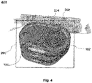
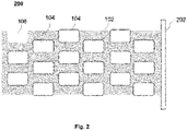
  • Fig.1 , Fig. 2 , Fig. 3 and Fig. 4 are pictorial representation illustrating a side cross-section 100 of one or more splicing cassettes 102 without a plurality of foldable sub-cassettes, a side cross-section of one or more splicing cassettes stack 200 without the plurality of foldable sub-cassettes, where one or more splicing cassettes stacked on top of each other, a perspective view 300 of one or more splicing cassettes stack 200 without the plurality of foldable sub-cassettes, a perspective view 400 of one or more splicing cassettes, without the plurality of foldable sub-cassettes, having one or more splice protectors 104 respectively in accordance with one or more embodiments of the present disclosure.
  • a splice closure comprises one or more splicing cassettes.
  • Each of one or more splicing cassettes has a plurality of foldable sub-cassettes and each of the plurality of foldable sub-cassettes has one or more splice protectors.
  • each of the plurality of foldable sub-cassettes is hinged to adjacent foldable sub-cassettes such that each of the plurality of foldable sub-cassettes of one or more splicing cassettes is arranged horizontally to enable splicing of one intermittently bonded ribbon (IBR) or a ribbon with 12 optical transmission elements on each of the plurality of foldable sub-cassettes.
  • IBR intermittently bonded ribbon
  • Each of the 12 optical transmission elements has a different colour.
  • the plurality of foldable sub-cassettes is folded on to a base cassette to form one or more splicing cassettes, and one or more splicing cassettes are stacked parallel to each other in the splice closure.
  • one or more splice protectors on the plurality of foldable sub-cassettes of a splicing cassette are arranged in such a manner that each of one or more splice protectors is unaligned to the adjacent foldable sub-cassettes of the splicing cassette.
  • Each of the plurality of foldable sub-cassettes has one or more cavities to accommodate one or more splice protectors of the adjacent foldable sub-cassettes in one or more splicing cassette.
  • the one or more splice protectors are defined by a splice protector thickness, and each of the plurality of foldable sub-cassettes is defined by a sub-cassette thickness.
  • the splice protector thickness is greater than the sub-cassette thickness.
  • Each of the plurality of foldable sub-cassettes is used to splice the intermittently bonded ribbon, and each optical transmission element of the intermittently bonded ribbon is differently coloured.
  • the splice protectors are a ribbon protector and the number of splice protectors is 12.
  • one or more splicing cassettes stack 200 may be formed by one or more splicing cassettes 102 arranged in a stacked manner. Particularly, one or more splicing cassettes (trays) may be used or incorporated in a splice closure or enclosure.
  • one or more splicing cassettes 102 may include one or more cavities 106 to accommodate one or more splice protectors 104. Each of one or more splice protectors 104 may protect spliced plurality of optical transmission elements such as optical fibers, intermittently bonded optical fiber ribbons etc.
  • each of one or more splice protectors 104 may protect spliced 12 fiber intermittently bonded optical fiber ribbon.
  • one or more cavities 106 may accommodate any other suitable components used in conjunction with the splice closure.
  • one or more splicing cassettes 102 may be connected with each other removably and rotatably via hinged structures or any other suitable means. Particularly, one or more splicing cassettes 102 may be rotatably hinged to each other along an axis at the same backplane.
  • one or more splicing cassettes stack 200 may be removably hinged to a supporting structure 202 along an axis through an attachment means 204 (as shown in Fig. 4 ) from one side.
  • the attachment means 204 may be any type of fasteners, screws or elements having snap-fit capabilities.
  • one or more splicing cassettes stack 200, and one or more splice protectors 104 may be protruded on adjacent cassettes/trays and may be placed in such a manner that one or more splice protectors are unaligned i.e., not under each other.
  • each splicing cassette of one or more splicing cassettes 102 may be defined by a thickness and each splice protector of one or more splice protectors 104 may be defined by a splice protector diameter and a splice protector thickness.
  • each of the one or more splicing cassettes 102 may have the thickness less than the splice protector diameter. This dimensional aspect allows the protrusion of each of the one or more splice protectors 104 on the adjacent cassettes/trays in the one or more splicing cassettes stack 200.
  • each of the one or more splice protectors 104 may have the splice protector diameter of 5.8mm.
  • the splice protector diameter of each of the one or more splice protectors 104 may vary.
  • each of the one or more splicing cassettes 102 has three splice protectors that can accommodate three intermittently bonded optical fiber ribbons in each of the three splice protectors.
  • the number of splice protectors may be more than or less than three in each of the one or more splicing cassettes 102.
  • each intermittently bonded optical fiber ribbon may accommodate 12 optical fibers of different colour.
  • the number and colour of the optical fibers in the intermittently bonded optical fiber ribbon may vary.
  • each of the one or more splicing cassettes 102 may have three optical fibers of the same colour.
  • each of the one or more splicing cassettes 102 may have the one or more cavities to accommodate protruded splice protectors (or any other component) on the adjacent cassettes that leads to high density packing of the plurality of optical transmission elements.
  • Fig. 5 , Fig. 6 , Fig. 7 and Fig. 8 are pictorial representation illustrating a side cross-section of one or more splicing cassettes/trays 500 with a base cassette 502 and the plurality of foldable sub-cassettes (trays) 502a, 502b in a closed configuration, a side cross-section of the one or more splicing cassettes/trays 500 in a semi-open configuration, a side cross-section of the one or more splicing cassettes/trays 500 in an open configuration and a side cross-section of the one or more splicing cassettes stack 600 comprising the one or more splicing cassettes 500 having the base cassette 502 and the plurality of foldable sub-cassettes 502a, 502b stacked in parallel respectively in accordance with one or more embodiments of the present disclosure.
  • the one or more splicing cassettes/trays 500 may be incorporated in the splice enclosure (or closure).
  • the one or more splicing cassettes 500 having the plurality of foldable sub-cassettes 502a, 502b are formed using a main cassette/tray 502 and the plurality of foldable sub-cassettes/sub-trays 502a, 502b, where the main cassette 502 acts as the base cassette/tray.
  • Each of the plurality of foldable sub-cassettes 502a, 502b is connected with each other through a connecting means 504 that allows connection as well as movement of the plurality of foldable sub-cassettes 502a, 502b in operational condition (as illustrated in FIG. 6 and FIG. 7 ).
  • the plurality of foldable sub-cassettes 502a, 502b is foldable in accordance with an axis of the base cassette/tray 502.
  • the number of the plurality of foldable sub-cassettes may be more than two 502a, 502b, 502c Vietnamese502n.
  • each of the base cassette 502 and the plurality of foldable sub-cassettes 502a, 502b may include the one or more splice protectors 104. This arrangement forms the one or more splicing cassettes 500 with three splice protectors.
  • the one or more splicing cassettes 500 having the base cassette 502 and the plurality of foldable sub-cassettes 502a, 502b may have the one or more cavities 106.
  • each of the one or more splice protectors 104 may be protruded into adjacent sub-cassette and the base cassette and may be unaligned to each other.
  • one or more splicing cassettes 500 having the base cassette 502 and the plurality of foldable sub-cassettes 502a, 502b may have the one or more cavities 106 to accommodate the one or more splice protectors 104 in the adjacent cassettes (as illustrated in FIGS. 5-7 ).
  • the base cassette 502 may be a thicker cassette.
  • the plurality of foldable sub-cassettes 502a, 502b may be thinner sub-cassettes as compared to the base cassette 502.
  • each of the plurality of foldable sub-cassettes may be defined by a sub-cassette thickness, where the splice protector thickness is greater than the sub-cassette thickness.
  • the base cassette 502 has plurality of foldable sub-cassettes 502a, 502b, that are hinged and foldable, creates two separate zones (i.e., the base cassette and the plurality of foldable sub-cassettes arranged horizontally).
  • the plurality of optical transmission elements may be spliced in each of the base cassette 502 and the plurality of foldable sub-cassettes 502a, 502b, i.e., in the two separate zones.
  • one 12F intermittently bonded optical fiber ribbon or a ribbon with 12 optical transmission elements, and each of the 12 optical transmission elements may have different colour, may be spliced in each of the thick cassettes and thin sub-cassettes in two separate zones.
  • the one or more splicing cassettes stack 600 may be formed by the one or more splicing cassettes 500 arranged in a stacked manner.
  • the one or more splicing cassettes stack 600 may be removably hinged to the supporting structure 202 along an axis through the attachment means from one side.
  • Fig. 9 and Fig. 10 are pictorial representations illustrating a different exemplary foldable configuration utilized in the one or more splicing cassettes without the plurality of foldable sub cassettes and with the plurality of the foldable sub-cassettes respectively in accordance with one or more embodiments of the present disclosure.
  • the plurality of foldable sub-cassettes 502a, 502b may be folded endlessly from the base cassette 502 like an endless chain.
  • the plurality of foldable sub-cassettes 502a, 502b, 502c may hinge at one axis i.e., at the same backplane with the help of the hinge/ connecting means 504.
  • the one or more splicing cassette 500 may utilize a book-fold configuration 700 as shown in FIG. 9 and a Z-fold configuration 800 as shown in FIG. 10 to stack the plurality of foldable sub-cassettes 502a, 502b, 502c... 502n one to the other.
  • the plurality of the optical transmission elements such as two intermittently bonded optical fiber ribbons, may be spliced in the same thickness as the conventional single thicker cassette (or single element cassette) by keeping each of the plurality of the optical transmission elements to be separated.
  • the one or more splicing tray 500 consists of the plurality of foldable sub-cassettes 502a, 502b ,....502n that fold into each other and into the base cassette 502, doubles the amount of splicing in the same space whilst keeping the cassettes perfectly separated.
  • the high-density splicing cassette is a double-density single element splicing cassette that helps increasing capacity of telecommunications enclosures such as splice enclosures/closures or terminals.
  • the splice enclosures/closures may be mounted in indoor as well as in outdoor environments and are used to protect cable elements such as stripped fiber optic cable and fiber optic splices.
  • the splice enclosures may be mounted on poles or walls, in junction boxes, in below-grade vaults or the like.
  • the splice enclosures act as a housing, in which a plurality of optical transmission elements is fanned out that are situated at the end of fiber routing paths.
  • the splicing cassette(s), also termed as a splicing tray(s), mounted in the splice enclosures picks up the plurality of optical transmission elements and their reserves.
  • the splicing cassette may be made from plastic and other suitable material.
  • the splicing cassette is a removable element in order to assemble the plurality of optical transmission elements with a splice unit.
  • the plurality of optical transmission elements may be, but not limited to, optical fibers and optical fiber ribbons such as intermittently bonded optical fiber ribbons or the like.
  • Fig. 11 is a pictorial representation illustrating a splice protector from the one or more splice protectors in accordance with an embodiment of the present disclosure.
  • one or more splice protectors 104 includes an outer tube 902, a strength member 904 and an inner tube 906.
  • the outer tube 902 is a shrink tube that encapsulates the strength member 904 and the inner tube 906.
  • the outer tube 902 may be made from any suitable material, such as, but not limited to, polymers, having capability of shrinking.
  • the strength member 904 may be made from ceramic, stainless steel or other suitable material.
  • the inner tube 906 is a fiber tube, where the fiber tube encapsulates the plurality of optical transmission elements. Subsequently, the outer tube 902 and the strength member 904 protects the inner tube 906, thereby protecting the plurality of optical transmission elements to avoid losses in optical properties of the plurality of optical transmission elements.
  • one or more splice protectors 104 may have the splice protector diameter of 5.8 millimeters.
  • one or more splice protectors 104 may be made flexible and formed in such a way that when inserted/placed in a cavity of the one or more cavities 106, the splice protector may deform and take the shape of the cavity.
  • the splice protector may be a ribbon protector.
  • the number of the one or more splice protectors may be 12.
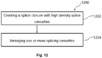
  • Fig. 12 is a flowchart illustrating a method for creating the splice closure with high density splice cassettes in accordance with an embodiment of the present disclosure.
  • the method 1200 starts at step 1202 and proceeds to step 1204.
  • creating a splice closure with high density splice cassettes comprises creating one or more splicing cassettes (500), and each of the one or more splicing cassettes (500) has a plurality of foldable sub-cassettes (502a, 502b), and each of the plurality of foldable sub-cassettes (502a, 502b) has one or more splice protectors (104).
  • step 1204 arranging the one or more splicing cassettes (500) in anyone configuration selected from an open configuration and a closed configuration.
  • the aforementioned arrangement allows packing more splices in a given volume and increases density of the splice enclosure.
  • the above-mentioned arrangements double the amount of splicing in the same space whilst keeping the trays perfectly separated.
  • the present disclosure provides a unique design and arrangement of splicing cassettes in order to achieve a high-density splicing cassette.

Landscapes

  • Physics & Mathematics (AREA)
  • General Physics & Mathematics (AREA)
  • Optics & Photonics (AREA)
  • Light Guides In General And Applications Therefor (AREA)
  • Connections Effected By Soldering, Adhesion, Or Permanent Deformation (AREA)

Abstract

The present disclosure discloses a splice closure includes one or more splicing cassettes (500), and each of the one or more splicing cassettes (500) has foldable sub-cassettes (502a, 502b). In particular, each of the plurality of foldable sub-cassettes (502a, 502b) further has one or more splice protectors (104). Moreover, the one or more splicing cassettes (500) are arranged in anyone configuration selected from an open configuration and a closed configuration.

Description

    TECHNICAL FIELD
  • Embodiments of the present disclosure relate to the field optical communications. And more particularly, relates to splice closure with high-density splice cassettes.
  • The present application claims the benefit of Indian Application No. 202111014652 titled "Splice Closure With High-density Splice Cassettes" filed by the applicant on 31st March 2021, which is incorporated herein by reference in its entirety.
  • Background Art
  • Optical communication networks play a vital role in today's networking infrastructure and long-haul communication. The optical communication networks are designed to meet the demands, such as high bandwidth, of end-users that lead to data, video, audio, or the like transmissions. Endeavors to meet the demands and to provide high bandwidth have been made using various techniques such as digital subscriber line, asynchronous digital subscriber line, integrated services digital network or the like. However, these conventional techniques fail to provide adequate bandwidth as well as are not economical for all the end-users.
  • With the advent of technology and to meet the demands, various optical fiber distribution systems and equipment have been introduced. Typically, the optical fiber distribution systems include fiber management trays mounted in telecommunications enclosures or splice closures or at other suitable locations. In general, the fiber management trays are used in managing and storing optical fibers and optical splices. Further, the fiber management trays comprise fiber routing paths that allow storage of excess length of the optical fibers without degrading optical properties of the optical fibers.
  • Generally, operators splice optical fibers in different fiber management trays. Firstly, single circuit (SC) trays are used to connect individual customers by splicing typically two fibers in one single thin tray. When cable elements such as the optical fibers are spliced to cable elements, mostly 12 optical fibers of that cable element are spliced in one single thicker tray. These trays are called single elements (SE) trays or cassettes.
  • The conventional fiber management trays come with limited splicing capacity. Further, for example, with intermittently bonded optical fiber ribbons, although the splicing capacity may be increased in the single thicker tray, however, this leads to inability to differentiate between two fiber elements, such as the optical fibers, spliced in the single thicker tray. In cases, if two intermittently bonded optical fiber ribbons are spliced in the single thicker tray, then colour of the optical fibers will appear twice in the single thicker tray leading to confusion and faulty fiber links.
  • Thus, there is an urgent need for a technical solution that overcomes the above stated limitations in the prior and addresses above hardware constraints by improvements in the fiber management trays for increasing the splicing capacity.
  • Hence, the present disclosure focuses to ameliorate the aforementioned problems by providing a high-density splice closure.
  • SUMMARY OF THE DISCLOSURE
  • Embodiments of the present disclosure provide a splice closure with high density splice cassettes. In particular, the splice closure comprises one or more splicing cassettes. Moreover, each of one or more splicing cassettes has a plurality of foldable sub-cassettes. Further, each of the plurality of foldable sub-cassettes has one or more splice protectors.
  • According to a first aspect, the splicing cassettes are arranged in an open configuration.
  • In accordance with an embodiment of the present disclosure, in the open configuration of one or more splicing cassettes, each of the plurality of foldable sub-cassettes is hinged to adjacent foldable sub-cassettes. In particular, the sub-cassettes are hinged such that each of the plurality of foldable sub-cassettes of one or more splicing cassettes is arranged horizontally. Moreover, the horizontally arranged one or more splicing cassette enables splicing of one intermittently bonded ribbon (IBR) or a ribbon.
  • In accordance with an embodiment of the present disclosure, the intermittently bonded ribbon (IBR) has 12 optical transmission elements on each of the plurality of foldable sub-cassettes.
  • In accordance with an embodiment of the present disclosure, each of the 12 optical transmission elements has a different colour.
  • According to a second aspect, the splicing cassettes are arranged in a closed configuration.
  • in the closed configuration of one or more splicing cassettes, the plurality of foldable sub-cassettes is folded on to a base cassette to form one or more splicing cassettes. In particular, one or more splicing cassettes are stacked parallel to each other in the splice closure. Moreover, one or more splice protectors on the plurality of foldable sub-cassettes of a splicing cassette are arranged in such a manner that each of one or more splice protectors is unaligned to the adjacent foldable sub-cassettes of the splicing cassette.
  • In accordance with an embodiment of the present disclosure, each of the plurality of foldable sub-cassettes has one or more cavities to accommodate one or more splice protectors of the adjacent foldable sub-cassettes in one or more splicing cassette.
  • In accordance with an embodiment of the present disclosure, the splice protectors are defined by a splice protector thickness and each of the plurality of foldable sub-cassettes is defined by a sub-cassette thickness.
  • In accordance with an embodiment of the present disclosure, the splice protector thickness is greater than the sub-cassette thickness.
  • In accordance with an embodiment of the present disclosure, each of the plurality of foldable sub-cassettes is used to splice the intermittently bonded ribbon. In particular, each optical transmission element of the intermittently bonded ribbon is differently coloured.
  • In accordance with an embodiment of the present disclosure, one or more splice protectors are a ribbon protector.
  • In accordance with an embodiment of the present disclosure, the number of one or more splice protectors is 12.
  • According to the fourth aspect of the disclosure, the method includes arranging one or more splicing cassettes in anyone configuration selected from an open configuration and a closed configuration.
  • Another embodiment of the present disclosure relates to a method for creating a splice closure with high density splice cassettes. The method includes creating one or more splicing cassettes, and each of one or more splicing cassettes has a plurality of foldable sub-cassettes, and each of the plurality of foldable sub-cassettes has one or more splice protectors.
  • According to the fourth aspect of the disclosure, the method includes arranging one or more splicing cassettes in anyone configuration selected from an open configuration and a closed configuration.
  • In accordance with an embodiment of the present disclosure, in the open configuration of one or more splicing cassettes, the each of the plurality of foldable sub-cassettes is hinged to adjacent foldable sub-cassette and arranged horizontally for splicing of one intermittently bonded ribbon (IBR) or a ribbon.
  • In accordance with an embodiment of the present disclosure, in the closed configuration of one or more splicing cassettes, the plurality of foldable sub-cassettes is folded on to a base cassette forming one or more splicing cassettes.
  • According to the fifth aspect of the disclosure, the high-density splice closure has double density single element splicing cassettes with improved splicing capacity.
  • According to the sixth aspect of the disclosure, the double density single element splicing cassettes provides optical transmission elements such as optical fibers and optical fiber ribbons.
  • According to the foregoing solutions are attained by employing a splice closure with high density splice cassettes and a method for creating the splice closure.
  • BRIEF DESCRIPTION OF DRAWINGS
  • To describe the technical solutions in the embodiments of the present disclosure or in the prior art more clearly, the following briefly describes the accompanying drawings required for describing the embodiments or the prior art. Apparently, the accompanying drawings in the following description merely show some embodiments of the present disclosure, and a person of ordinary skill in the art can derive other implementations from these accompanying drawings without creative efforts. All of the embodiments or the implementations shall fall within the protection scope of the present disclosure.
    • Fig.1 is a pictorial representation illustrating a side cross-section of one or more splicing cassettes (trays) without a plurality of foldable sub-cassettes in accordance with an embodiment of the present disclosure;
    • Fig. 2 is a pictorial representation illustrating a side cross-section of one or more splicing cassettes, without the plurality of foldable sub-cassettes, stacked on top of each other in accordance with an embodiment of the present disclosure;
    • Fig. 3 is a pictorial representation illustrating a perspective view of one or more splicing cassettes stack without the plurality of foldable sub-cassettes in accordance with an embodiment of the present disclosure;
    • Fig. 4 is a pictorial representation illustrating a perspective view of one or more splicing cassettes without the plurality of foldable sub-cassettes having one or more splice protectors in accordance with an embodiment of the present disclosure;
    • Fig. 5 is a pictorial representation illustrating a side cross-section of one or more splicing cassettes with the plurality of foldable sub-cassettes in accordance with one embodiment of the present disclosure;
    • Fig. 6 is a pictorial representation illustrating a side cross-section of one or more splicing cassettes with the plurality of foldable sub-cassettes in accordance with another embodiment of the present disclosure;
    • Fig. 7 is a pictorial representation illustrating a side cross-section of one or more splicing cassettes with the plurality of foldable sub-cassettes in accordance with yet another embodiment of the present disclosure;
    • Fig. 8 is a pictorial representation illustrating a side cross-section of one or more splicing cassettes, with the plurality of foldable sub-cassettes, stacked on top of each other;
    • Fig. 9 is a pictorial representation illustrating a different exemplary foldable configuration utilized in one or more splicing cassettes without the plurality of foldable sub cassettes in accordance with one embodiment of the present disclosure;
    • Fig. 10 is a pictorial representation illustrating a different exemplary foldable configuration utilized in one or more splicing cassettes with the plurality of the foldable sub-cassettes in accordance with another embodiment of the present disclosure;
    • Fig. 11 is a pictorial representation illustrating a splice protector from one or more splice protectors in accordance with an embodiment of the present disclosure;
    • Fig. 12 is a flowchart illustrating a method for creating the splice closure with high density splice cassettes in accordance with an embodiment of the present disclosure.
    REFERENCE LIST
    • Splicing Cassettes 102
    • Splice Protectors 104
    • Cavities 106
    • Splicing Cassettes Stack 200
    • Supporting Structure 202
    • Attachment Means 204
    • Base Cassette 502
    • Foldable Sub-cassettes 502a, 502b
    • Connecting Means 504
    • Outer Tube 902
    • Strength Member 904
    • Inner Tube 906
  • The method and system are illustrated in the accompanying drawings, throughout which like reference letters indicate corresponding parts in the various figures.
  • It should be noted that the accompanying figure is intended to present illustrations of exemplary embodiments of the present disclosure. This figure is not intended to limit the scope of the present disclosure. It should also be noted that the accompanying figure is not necessarily drawn to scale.
  • DESCRIPTION OF EMBODIMENTS
  • Those skilled in the art will be aware that the present disclosure is subject to variations and modifications other than those specifically described. It is to be understood that the present disclosure includes all such variations and modifications. The disclosure also includes all such steps, features, compositions and compounds referred to or indicated in this specification, individually or collectively, and any and all combinations of any or more of such steps or features.
  • Definitions:
  • For convenience, before further description of the present disclosure, certain terms employed in the specification, and examples are collected here. These definitions should be read in the light of the remainder of the disclosure and understood as by a person of skill in the art. The terms used herein have the meanings recognized and known to those of skill in the art, however, for convenience and completeness, particular terms and their meanings are set forth below.
  • The articles "a", "an" and "the" are used to refer to one or to more than one (i.e., to at least one) of the grammatical object of the article.
  • The terms "comprise" and "comprising" are used in the inclusive, open sense, meaning that additional elements may be included. It is not intended to be construed as "consists of only". Throughout this specification, unless the context requires otherwise the word "comprise", and variations such as "comprises" and "comprising", will be understood to imply the inclusion of a stated element or step or group of element or steps but not the exclusion of any other element or step or group of element or steps.
  • The term "including" is used to mean "including but not limited to". "Including" and "including but not limited to" are used interchangeably.
  • Following terms shall apply throughout the present disclosure:
  • An optical fiber refers to a medium associated with transmission of information over long distances in form of light pulses. The optical fiber uses light to transmit voice and data over long distances. Further, the intermittently bonded optical fiber ribbon comprises a plurality of optical fibers placed in parallel to each other and bonded intermittently with a special material such as matrix material to impart rolling capability along a width of the intermittently bonded optical fiber ribbon.
  • Fig.1, Fig. 2, Fig. 3 and Fig. 4 are pictorial representation illustrating a side cross-section 100 of one or more splicing cassettes 102 without a plurality of foldable sub-cassettes, a side cross-section of one or more splicing cassettes stack 200 without the plurality of foldable sub-cassettes, where one or more splicing cassettes stacked on top of each other, a perspective view 300 of one or more splicing cassettes stack 200 without the plurality of foldable sub-cassettes, a perspective view 400 of one or more splicing cassettes, without the plurality of foldable sub-cassettes, having one or more splice protectors 104 respectively in accordance with one or more embodiments of the present disclosure. In particular, a splice closure comprises one or more splicing cassettes. Each of one or more splicing cassettes has a plurality of foldable sub-cassettes and each of the plurality of foldable sub-cassettes has one or more splice protectors.
  • In an open configuration of one or more splicing cassettes, each of the plurality of foldable sub-cassettes is hinged to adjacent foldable sub-cassettes such that each of the plurality of foldable sub-cassettes of one or more splicing cassettes is arranged horizontally to enable splicing of one intermittently bonded ribbon (IBR) or a ribbon with 12 optical transmission elements on each of the plurality of foldable sub-cassettes. Each of the 12 optical transmission elements has a different colour.
  • In a closed configuration of one or more splicing cassettes, the plurality of foldable sub-cassettes is folded on to a base cassette to form one or more splicing cassettes, and one or more splicing cassettes are stacked parallel to each other in the splice closure. Particularly, one or more splice protectors on the plurality of foldable sub-cassettes of a splicing cassette are arranged in such a manner that each of one or more splice protectors is unaligned to the adjacent foldable sub-cassettes of the splicing cassette. Each of the plurality of foldable sub-cassettes has one or more cavities to accommodate one or more splice protectors of the adjacent foldable sub-cassettes in one or more splicing cassette.
  • The one or more splice protectors are defined by a splice protector thickness, and each of the plurality of foldable sub-cassettes is defined by a sub-cassette thickness. In particular, the splice protector thickness is greater than the sub-cassette thickness.
  • Each of the plurality of foldable sub-cassettes is used to splice the intermittently bonded ribbon, and each optical transmission element of the intermittently bonded ribbon is differently coloured.
  • The splice protectors are a ribbon protector and the number of splice protectors is 12.
  • Referring to FIG. 2, one or more splicing cassettes stack 200 may be formed by one or more splicing cassettes 102 arranged in a stacked manner. Particularly, one or more splicing cassettes (trays) may be used or incorporated in a splice closure or enclosure. In particular, one or more splicing cassettes 102 may include one or more cavities 106 to accommodate one or more splice protectors 104. Each of one or more splice protectors 104 may protect spliced plurality of optical transmission elements such as optical fibers, intermittently bonded optical fiber ribbons etc.
  • In an example, each of one or more splice protectors 104 may protect spliced 12 fiber intermittently bonded optical fiber ribbon.
  • Alternatively, in other embodiments of the present disclosure, one or more cavities 106 may accommodate any other suitable components used in conjunction with the splice closure.
  • Referring to Fig. 3, one or more splicing cassettes 102 may be connected with each other removably and rotatably via hinged structures or any other suitable means. Particularly, one or more splicing cassettes 102 may be rotatably hinged to each other along an axis at the same backplane.
  • In accordance with an embodiment of the present disclosure, one or more splicing cassettes stack 200 may be removably hinged to a supporting structure 202 along an axis through an attachment means 204 (as shown in Fig. 4) from one side. Particularly, the attachment means 204 may be any type of fasteners, screws or elements having snap-fit capabilities.
  • In accordance with an embodiment of the present disclosure, one or more splicing cassettes stack 200, and one or more splice protectors 104 may be protruded on adjacent cassettes/trays and may be placed in such a manner that one or more splice protectors are unaligned i.e., not under each other.
  • In accordance with an embodiment of the present disclosure, each splicing cassette of one or more splicing cassettes 102 may be defined by a thickness and each splice protector of one or more splice protectors 104 may be defined by a splice protector diameter and a splice protector thickness. In particular, each of the one or more splicing cassettes 102 may have the thickness less than the splice protector diameter. This dimensional aspect allows the protrusion of each of the one or more splice protectors 104 on the adjacent cassettes/trays in the one or more splicing cassettes stack 200.
  • In an exemplary example, each of the one or more splice protectors 104 may have the splice protector diameter of 5.8mm.
  • Alternatively in other exemplary examples and embodiments, the splice protector diameter of each of the one or more splice protectors 104 may vary.
  • For instance, each of the one or more splicing cassettes 102 has three splice protectors that can accommodate three intermittently bonded optical fiber ribbons in each of the three splice protectors.
  • Alternatively, the number of splice protectors may be more than or less than three in each of the one or more splicing cassettes 102.
  • In accordance with an embodiment of the present disclosure, each intermittently bonded optical fiber ribbon may accommodate 12 optical fibers of different colour. Alternatively, the number and colour of the optical fibers in the intermittently bonded optical fiber ribbon may vary.
  • In an example, each of the one or more splicing cassettes 102 may have three optical fibers of the same colour.
  • In accordance with another aspect of the present disclosure, each of the one or more splicing cassettes 102 may have the one or more cavities to accommodate protruded splice protectors (or any other component) on the adjacent cassettes that leads to high density packing of the plurality of optical transmission elements.
  • Fig. 5, Fig. 6, Fig. 7 and Fig. 8 are pictorial representation illustrating a side cross-section of one or more splicing cassettes/trays 500 with a base cassette 502 and the plurality of foldable sub-cassettes (trays) 502a, 502b in a closed configuration, a side cross-section of the one or more splicing cassettes/trays 500 in a semi-open configuration, a side cross-section of the one or more splicing cassettes/trays 500 in an open configuration and a side cross-section of the one or more splicing cassettes stack 600 comprising the one or more splicing cassettes 500 having the base cassette 502 and the plurality of foldable sub-cassettes 502a, 502b stacked in parallel respectively in accordance with one or more embodiments of the present disclosure. In particular, the one or more splicing cassettes/trays 500 may be incorporated in the splice enclosure (or closure).
  • In accordance with an aspect of the present disclosure, the one or more splicing cassettes 500 having the plurality of foldable sub-cassettes 502a, 502b are formed using a main cassette/tray 502 and the plurality of foldable sub-cassettes/sub-trays 502a, 502b, where the main cassette 502 acts as the base cassette/tray. Each of the plurality of foldable sub-cassettes 502a, 502b is connected with each other through a connecting means 504 that allows connection as well as movement of the plurality of foldable sub-cassettes 502a, 502b in operational condition (as illustrated in FIG. 6 and FIG. 7).
  • In particular, the plurality of foldable sub-cassettes 502a, 502b is foldable in accordance with an axis of the base cassette/tray 502. For illustration purposes, only two foldable sub-cassettes 502a, 502b have been shown, however, the number of the plurality of foldable sub-cassettes may be more than two 502a, 502b, 502c.....502n.
  • In accordance with an aspect of the present disclosure, each of the base cassette 502 and the plurality of foldable sub-cassettes 502a, 502b may include the one or more splice protectors 104. This arrangement forms the one or more splicing cassettes 500 with three splice protectors.
  • In this configuration, the one or more splicing cassettes 500 having the base cassette 502 and the plurality of foldable sub-cassettes 502a, 502b may have the one or more cavities 106. In particular, each of the one or more splice protectors 104 may be protruded into adjacent sub-cassette and the base cassette and may be unaligned to each other. Moreover, one or more splicing cassettes 500 having the base cassette 502 and the plurality of foldable sub-cassettes 502a, 502b may have the one or more cavities 106 to accommodate the one or more splice protectors 104 in the adjacent cassettes (as illustrated in FIGS. 5-7).
  • In an implementation of the present disclosure, the base cassette 502 may be a thicker cassette. And, the plurality of foldable sub-cassettes 502a, 502b may be thinner sub-cassettes as compared to the base cassette 502. In addition, each of the plurality of foldable sub-cassettes may be defined by a sub-cassette thickness, where the splice protector thickness is greater than the sub-cassette thickness. Particularly, the base cassette 502 has plurality of foldable sub-cassettes 502a, 502b, that are hinged and foldable, creates two separate zones (i.e., the base cassette and the plurality of foldable sub-cassettes arranged horizontally).
  • In accordance with an aspect of the present disclosure, the plurality of optical transmission elements may be spliced in each of the base cassette 502 and the plurality of foldable sub-cassettes 502a, 502b, i.e., in the two separate zones. For example, one 12F intermittently bonded optical fiber ribbon or a ribbon with 12 optical transmission elements, and each of the 12 optical transmission elements may have different colour, may be spliced in each of the thick cassettes and thin sub-cassettes in two separate zones.
  • In accordance with an aspect of the present disclosure, the one or more splicing cassettes stack 600 (as illustrated in Fig. 8) may be formed by the one or more splicing cassettes 500 arranged in a stacked manner. The one or more splicing cassettes stack 600 may be removably hinged to the supporting structure 202 along an axis through the attachment means from one side.
  • Fig. 9 and Fig. 10 are pictorial representations illustrating a different exemplary foldable configuration utilized in the one or more splicing cassettes without the plurality of foldable sub cassettes and with the plurality of the foldable sub-cassettes respectively in accordance with one or more embodiments of the present disclosure. In particular, the plurality of foldable sub-cassettes 502a, 502b may be folded endlessly from the base cassette 502 like an endless chain. Moreover, the plurality of foldable sub-cassettes 502a, 502b, 502c may hinge at one axis i.e., at the same backplane with the help of the hinge/ connecting means 504.
  • For example, if the number of the plurality of foldable sub-cassettes is 3, then all 3 foldable sub-cassettes may hinge at the same backplane. Similarly, if the number of the plurality of foldable sub-cassettes is 4, then all 4 foldable sub-cassettes may hinge at the same backplane.
  • The one or more splicing cassette 500 may utilize a book-fold configuration 700 as shown in FIG. 9 and a Z-fold configuration 800 as shown in FIG. 10 to stack the plurality of foldable sub-cassettes 502a, 502b, 502c... 502n one to the other.
  • In alternative embodiments of the present disclosure, other suitable folding configurations may also be utilized.
  • In accordance with an aspect of the present disclosure, with intermittently bonded optical fiber ribbons, although the splicing capacity may be increased in conventional single thicker cassettes/trays, however, this leads to inability to clearly differentiate between two optical transmission elements, such as the optical fibers, spliced in the conventional single thicker cassette/tray.
  • For example, if two intermittently bonded optical fiber ribbons are spliced in the conventional single thicker cassette, then colour of the optical fibers will appear twice in the conventional single thicker cassette leading to confusion and faulty fiber links. Thus, by splitting the conventional single thicker cassette into the plurality of foldable sub-cassettes 502a, 502b, the plurality of the optical transmission elements, such as two intermittently bonded optical fiber ribbons, may be spliced in the same thickness as the conventional single thicker cassette (or single element cassette) by keeping each of the plurality of the optical transmission elements to be separated.
  • Hence, the one or more splicing tray 500 consists of the plurality of foldable sub-cassettes 502a, 502b ,....502n that fold into each other and into the base cassette 502, doubles the amount of splicing in the same space whilst keeping the cassettes perfectly separated.
  • In accordance with an aspect of the present disclosure, the high-density splicing cassette (tray) is a double-density single element splicing cassette that helps increasing capacity of telecommunications enclosures such as splice enclosures/closures or terminals. In particular, the splice enclosures/closures may be mounted in indoor as well as in outdoor environments and are used to protect cable elements such as stripped fiber optic cable and fiber optic splices. Moreover, the splice enclosures may be mounted on poles or walls, in junction boxes, in below-grade vaults or the like. Further, the splice enclosures act as a housing, in which a plurality of optical transmission elements is fanned out that are situated at the end of fiber routing paths.
  • The splicing cassette(s), also termed as a splicing tray(s), mounted in the splice enclosures picks up the plurality of optical transmission elements and their reserves. The splicing cassette may be made from plastic and other suitable material. In particular, the splicing cassette is a removable element in order to assemble the plurality of optical transmission elements with a splice unit. The plurality of optical transmission elements may be, but not limited to, optical fibers and optical fiber ribbons such as intermittently bonded optical fiber ribbons or the like.
  • Fig. 11 is a pictorial representation illustrating a splice protector from the one or more splice protectors in accordance with an embodiment of the present disclosure. In particular, one or more splice protectors 104 includes an outer tube 902, a strength member 904 and an inner tube 906. In particular, the outer tube 902 is a shrink tube that encapsulates the strength member 904 and the inner tube 906. And, the outer tube 902 may be made from any suitable material, such as, but not limited to, polymers, having capability of shrinking. Moreover, the strength member 904 may be made from ceramic, stainless steel or other suitable material. Further, the inner tube 906 is a fiber tube, where the fiber tube encapsulates the plurality of optical transmission elements. Subsequently, the outer tube 902 and the strength member 904 protects the inner tube 906, thereby protecting the plurality of optical transmission elements to avoid losses in optical properties of the plurality of optical transmission elements.
  • In accordance with an aspect of the present disclosure, one or more splice protectors 104 may have the splice protector diameter of 5.8 millimeters. Particularly, one or more splice protectors 104 may be made flexible and formed in such a way that when inserted/placed in a cavity of the one or more cavities 106, the splice protector may deform and take the shape of the cavity. Moreover, the splice protector may be a ribbon protector. And, the number of the one or more splice protectors may be 12.
  • Fig. 12 is a flowchart illustrating a method for creating the splice closure with high density splice cassettes in accordance with an embodiment of the present disclosure. The method 1200 starts at step 1202 and proceeds to step 1204. At step 1202, creating a splice closure with high density splice cassettes comprises creating one or more splicing cassettes (500), and each of the one or more splicing cassettes (500) has a plurality of foldable sub-cassettes (502a, 502b), and each of the plurality of foldable sub-cassettes (502a, 502b) has one or more splice protectors (104).
  • At step 1204, arranging the one or more splicing cassettes (500) in anyone configuration selected from an open configuration and a closed configuration.
  • may be noted that the flowchart 900 is explained to have above stated process steps, however, those skilled in the art would appreciate that the flowchart 900 may have more/less number of process steps which may enable all the above stated embodiments of the present disclosure.
  • Therefore, the aforementioned arrangement allows packing more splices in a given volume and increases density of the splice enclosure.
  • Advantageously, the above-mentioned arrangements double the amount of splicing in the same space whilst keeping the trays perfectly separated. Also, the present disclosure provides a unique design and arrangement of splicing cassettes in order to achieve a high-density splicing cassette.
  • The foregoing descriptions of specific embodiments of the present technology have been presented for purposes of illustration and description. They are not intended to be exhaustive or to limit the present technology to the precise forms disclosed, and obviously many modifications and variations are possible in light of the above teaching. The embodiments were chosen and described in order to best explain the principles of the present technology and its practical application, to thereby enable others skilled in the art to best utilize the present technology and various embodiments with various modifications as are suited to the particular use contemplated. It is understood that various omissions and substitutions of equivalents are contemplated as circumstance may suggest or render expedient, but such are intended to cover the application or implementation without departing from the spirit or scope of the claims of the present technology.
  • While several possible embodiments of the disclosure have been described above and illustrated in some cases, it should be interpreted and understood as to have been presented only by way of illustration and example, but not by limitation. Thus, the breadth and scope of a preferred embodiment should not be limited by any of the above-described exemplary embodiments.
  • It will be apparent to those skilled in the art that other embodiments of the disclosure will be apparent to those skilled in the art from consideration of the specification and practice of the disclosure. While the foregoing written description of the disclosure enables one of ordinary skill to make and use what is considered presently to be the best mode thereof, those of ordinary skill will understand and appreciate the existence of variations, combinations, and equivalents of the specific embodiment, method, and examples herein. The disclosure should therefore not be limited by the above described embodiment, method, and examples, but by all embodiments and methods within the scope of the disclosure. It is intended that the specification and examples be considered as exemplary, with the true scope of the disclosure being indicated by the claims.

Claims (15)

  1. A splice closure characterized in that:
    one or more splicing cassettes (500), wherein each of the one or more splicing cassettes (500) has a plurality of foldable sub-cassettes (502a, 502b), and each of the plurality of foldable sub-cassettes (502a, 502b) further has one or more splice protectors (104).
  2. The splice closure as claimed in claim 1, wherein the one or more splicing cassettes (500) are arranged in any one configuration selected from an open configuration and a closed configuration.
  3. The splice closure as claimed in claim 2, wherein in the open configuration of the one or more splicing cassettes (500), each of the plurality of foldable sub-cassettes (502a, 502b) is hinged to adjacent foldable sub-cassettes.
  4. The splice closure as claimed in claim 2 or claim 3, wherein in the open configuration each of the plurality of foldable sub-cassettes (502a, 502b) are arranged horizontally for splicing of one intermittently bonded ribbon (IBR) or a ribbon.
  5. The splice closure as claimed in claim 4, wherein each of the plurality of foldable sub-cassettes (502a, 502b) have 12 optical transmission elements.
  6. The splice closure as claimed in claim 5, wherein each of the 12 optical transmission elements has a different colour.
  7. The splice closure as claimed in claim 2 to 6, wherein, in a closed configuration of the one or more splicing cassettes (500), the plurality of foldable sub-cassettes (502a, 502b) is folded on to a base cassette (502) forming the one or more splicing cassettes (500).
  8. The splice closure as claimed in claim 7, wherein in the closed configuration the one or more splicing cassettes (500) are arranged parallelly in the splice closure.
  9. The splice closure as claimed in any preceding claim, wherein the one or more splice protectors (104) on the plurality of foldable sub-cassettes (502a, 502b) of a splicing cassette (500) are arranged unaligned to an adjacent foldable sub-cassettes of the splicing cassette (500).
  10. The splice closure as claimed in any preceding claim, wherein each of the plurality of foldable sub-cassettes (502a, 502b) have one or more cavities (106) operably configured to accommodate the one or more splice protectors (104) of an adjacent foldable sub-cassettes in the one or more splicing cassettes (500).
  11. The splice closure as claimed in any preceding claim, wherein the one or more splice protectors (104) are defined by a splice protector thickness and each of the plurality of foldable sub-cassettes (502a, 502b) is defined by a sub-cassette thickness.
  12. The splice closure as claimed in claim 11, wherein the splice protector thickness is more than the sub-cassette thickness.
  13. The splice closure as claimed in any preceding claim, wherein each of the plurality of foldable sub-cassettes (502a, 502b) splices an intermittently bonded ribbon and each optical transmission element of the intermittently bonded ribbon has a different colour.
  14. The splice closure as claimed in any preceding claim, wherein the one or more splice protectors (104) is a ribbon protector.
  15. The splice closure as claimed in any preceding claim, wherein a number of the one or more splice protectors is 12.
EP21199842.2A 2021-03-31 2021-09-29 Splice closure with high-density splice cassettes Pending EP4067960A1 (en)

Applications Claiming Priority (1)

Application Number Priority Date Filing Date Title
IN202111014652 2021-03-31

Publications (1)

Publication Number Publication Date
EP4067960A1 true EP4067960A1 (en) 2022-10-05

Family

ID=78293865

Family Applications (1)

Application Number Title Priority Date Filing Date
EP21199842.2A Pending EP4067960A1 (en) 2021-03-31 2021-09-29 Splice closure with high-density splice cassettes

Country Status (4)

Country Link
US (1) US20220317403A1 (en)
EP (1) EP4067960A1 (en)
AU (1) AU2022250131A1 (en)
WO (1) WO2022208541A1 (en)

Citations (7)

* Cited by examiner, † Cited by third party
Publication number Priority date Publication date Assignee Title
US6192180B1 (en) * 1997-12-02 2001-02-20 Korea Telecom Tray for splicing optical ribbon fibers
US20080226250A1 (en) * 2007-03-15 2008-09-18 Curtis Paul Gonzales Fiber optic categorization and management tray
EP2490059A1 (en) * 2011-02-17 2012-08-22 Tyco Electronics Raychem BVBA Fibre organizer
US20130011110A1 (en) * 2010-03-26 2013-01-10 Matthew John Kerry Optical fiber apparatus
US20140079365A1 (en) * 2012-09-18 2014-03-20 Clearfield, Inc. Optical fiber management system
US20190204521A1 (en) * 2017-12-28 2019-07-04 Afl Ig Llc Wall cabinets and fiber management trays
US20210018705A1 (en) * 2019-07-16 2021-01-21 Sterlite Technologies Limited Intermittently bonded optical fibre ribbon

Family Cites Families (15)

* Cited by examiner, † Cited by third party
Publication number Priority date Publication date Assignee Title
GB8729952D0 (en) * 1987-12-23 1988-02-03 British Telecomm Mounting assembly for optical equipment
FR2687743B1 (en) * 1992-02-21 1995-06-16 Mars Actel SET OF STACKED AND ARTICULATED MODULES.
US5450518A (en) * 1994-10-13 1995-09-12 At&T Corp. Optical fiber cable splice closure
US5689605A (en) * 1995-02-09 1997-11-18 Lucent Technologies Inc. Splice holder assembly for an optical fiber cable splice closure
JP3008879B2 (en) * 1997-02-26 2000-02-14 日本電気株式会社 Lightwave circuit mounting structure
TW364953B (en) * 1997-04-15 1999-07-21 Rxs Schrumpftech Garnituren Cable closure having a holding device for cassettes for depositing and splicing optical fibres
JPH11167029A (en) * 1997-12-05 1999-06-22 Fujikura Ltd Extra storage tray
FR2789497B1 (en) * 1999-02-04 2002-06-14 Cit Alcatel OPTICAL FIBER ORGANIZER
US6353697B1 (en) * 1999-07-30 2002-03-05 Lucent Technologies, Inc. Modular layered splice holder
WO2004051337A1 (en) * 2002-11-26 2004-06-17 Ccs Technology, Inc. Device for the structured storage or handling of optical waveguides
US7031588B2 (en) * 2004-04-27 2006-04-18 Commscope Solutions Properties, Llc Articulated high density fiber optic splice and termination shelf
US7200314B2 (en) * 2004-05-06 2007-04-03 Commscope Solutions Properties, Llc Carrier for multiple splice trays
CA2626947A1 (en) * 2005-10-24 2007-05-03 Tyco Electronics Corporation Fiber optic splice storage apparatus and methods for using the same
US7889961B2 (en) * 2008-03-27 2011-02-15 Corning Cable Systems Llc Compact, high-density adapter module, housing assembly and frame assembly for optical fiber telecommunications
US8494332B2 (en) * 2010-11-15 2013-07-23 Adc Telecommunications, Inc. Tray assembly for a fiber optic enclosure

Patent Citations (7)

* Cited by examiner, † Cited by third party
Publication number Priority date Publication date Assignee Title
US6192180B1 (en) * 1997-12-02 2001-02-20 Korea Telecom Tray for splicing optical ribbon fibers
US20080226250A1 (en) * 2007-03-15 2008-09-18 Curtis Paul Gonzales Fiber optic categorization and management tray
US20130011110A1 (en) * 2010-03-26 2013-01-10 Matthew John Kerry Optical fiber apparatus
EP2490059A1 (en) * 2011-02-17 2012-08-22 Tyco Electronics Raychem BVBA Fibre organizer
US20140079365A1 (en) * 2012-09-18 2014-03-20 Clearfield, Inc. Optical fiber management system
US20190204521A1 (en) * 2017-12-28 2019-07-04 Afl Ig Llc Wall cabinets and fiber management trays
US20210018705A1 (en) * 2019-07-16 2021-01-21 Sterlite Technologies Limited Intermittently bonded optical fibre ribbon

Also Published As

Publication number Publication date
US20220317403A1 (en) 2022-10-06
AU2022250131A1 (en) 2023-09-21
WO2022208541A1 (en) 2022-10-06

Similar Documents

Publication Publication Date Title
US6621975B2 (en) Distribution terminal for network access point
US7418184B1 (en) Fiber optic categorization and management tray
US8213760B2 (en) Fiber optic enclosure
US10295771B2 (en) Telecommunications terminal with removable modules
US10606009B2 (en) Cable distribution system with fan out devices
EP3673308B1 (en) Drop terminal
EP3435130A1 (en) Splitter module and enclosure for use therein
US20040042755A1 (en) Cassette for coiling and holding splices between conductors, and an organizer for a plurality of said cassettes
US12541071B2 (en) Cable port seal assembly
US12353040B2 (en) Adapter configured to permit a heat shrink splice holder portion of a fiber splice cassette to hold a mechanical crimp splice protector
EP4067960A1 (en) Splice closure with high-density splice cassettes
US20230152546A1 (en) Cable slack management apparatus for co-packaged opto-electrical devices
US20250231365A1 (en) Fiber-optic splice storage tray
US12578542B2 (en) Fiber optic component holder having a variably sized receiving portion for holding various sizes of fiber optical components or multiple fiber optical components
US20260023217A1 (en) Flexible Optical Fiber Splitter Assembly
US20260023235A1 (en) Flexible Optical Fiber Splice Tray Assembly
EP4273603B1 (en) Fiber optic closure
EP4641278A1 (en) Enclosure having a plurality of ports and one or more co-moulded plugs
US12001072B2 (en) Telecommunications cable management component housing
WO2022046492A1 (en) Fiber management assembly for drop terminal
GB2554647A (en) Optical fibre joint
CN111239914A (en) Optical cross-connect equipment for metropolitan area backbone transport network

Legal Events

Date Code Title Description
PUAI Public reference made under article 153(3) epc to a published international application that has entered the european phase

Free format text: ORIGINAL CODE: 0009012

STAA Information on the status of an ep patent application or granted ep patent

Free format text: STATUS: THE APPLICATION HAS BEEN PUBLISHED

AK Designated contracting states

Kind code of ref document: A1

Designated state(s): AL AT BE BG CH CY CZ DE DK EE ES FI FR GB GR HR HU IE IS IT LI LT LU LV MC MK MT NL NO PL PT RO RS SE SI SK SM TR

STAA Information on the status of an ep patent application or granted ep patent

Free format text: STATUS: REQUEST FOR EXAMINATION WAS MADE

17P Request for examination filed

Effective date: 20230405

RBV Designated contracting states (corrected)

Designated state(s): AL AT BE BG CH CY CZ DE DK EE ES FI FR GB GR HR HU IE IS IT LI LT LU LV MC MK MT NL NO PL PT RO RS SE SI SK SM TR

STAA Information on the status of an ep patent application or granted ep patent

Free format text: STATUS: EXAMINATION IS IN PROGRESS

17Q First examination report despatched

Effective date: 20240618