EP4067955A1 - Distribution rack - Google Patents
Distribution rack Download PDFInfo
- Publication number
- EP4067955A1 EP4067955A1 EP21180134.5A EP21180134A EP4067955A1 EP 4067955 A1 EP4067955 A1 EP 4067955A1 EP 21180134 A EP21180134 A EP 21180134A EP 4067955 A1 EP4067955 A1 EP 4067955A1
- Authority
- EP
- European Patent Office
- Prior art keywords
- optical fiber
- cassette
- cable
- guide
- distribution rack
- Prior art date
- Legal status (The legal status is an assumption and is not a legal conclusion. Google has not performed a legal analysis and makes no representation as to the accuracy of the status listed.)
- Withdrawn
Links
- 239000013307 optical fiber Substances 0.000 claims description 158
- 230000003287 optical effect Effects 0.000 claims description 3
- 239000000835 fiber Substances 0.000 abstract description 80
- 238000005452 bending Methods 0.000 description 17
- 238000005192 partition Methods 0.000 description 7
- 230000000717 retained effect Effects 0.000 description 5
- 238000007665 sagging Methods 0.000 description 5
- 230000004927 fusion Effects 0.000 description 4
- 238000000034 method Methods 0.000 description 3
- 238000010586 diagram Methods 0.000 description 2
- 238000009434 installation Methods 0.000 description 2
- 230000000149 penetrating effect Effects 0.000 description 2
- 239000011347 resin Substances 0.000 description 2
- 229920005989 resin Polymers 0.000 description 2
- 239000004760 aramid Substances 0.000 description 1
- 229920006231 aramid fiber Polymers 0.000 description 1
- 230000005540 biological transmission Effects 0.000 description 1
- 239000011248 coating agent Substances 0.000 description 1
- 238000000576 coating method Methods 0.000 description 1
- 239000011521 glass Substances 0.000 description 1
- 239000002184 metal Substances 0.000 description 1
- 230000001681 protective effect Effects 0.000 description 1
- 229910001220 stainless steel Inorganic materials 0.000 description 1
- 239000010935 stainless steel Substances 0.000 description 1
- 238000004804 winding Methods 0.000 description 1
Images









Classifications
-
- G—PHYSICS
- G02—OPTICS
- G02B—OPTICAL ELEMENTS, SYSTEMS OR APPARATUS
- G02B6/00—Light guides; Structural details of arrangements comprising light guides and other optical elements, e.g. couplings
- G02B6/44—Mechanical structures for providing tensile strength and external protection for fibres, e.g. optical transmission cables
- G02B6/4439—Auxiliary devices
- G02B6/444—Systems or boxes with surplus lengths
- G02B6/4453—Cassettes
- G02B6/4455—Cassettes characterised by the way of extraction or insertion of the cassette in the distribution frame, e.g. pivoting, sliding, rotating or gliding
-
- G—PHYSICS
- G02—OPTICS
- G02B—OPTICAL ELEMENTS, SYSTEMS OR APPARATUS
- G02B6/00—Light guides; Structural details of arrangements comprising light guides and other optical elements, e.g. couplings
- G02B6/44—Mechanical structures for providing tensile strength and external protection for fibres, e.g. optical transmission cables
- G02B6/4439—Auxiliary devices
- G02B6/444—Systems or boxes with surplus lengths
- G02B6/4452—Distribution frames
- G02B6/44524—Distribution frames with frame parts or auxiliary devices mounted on the frame and collectively not covering a whole width of the frame or rack
-
- G—PHYSICS
- G02—OPTICS
- G02B—OPTICAL ELEMENTS, SYSTEMS OR APPARATUS
- G02B6/00—Light guides; Structural details of arrangements comprising light guides and other optical elements, e.g. couplings
- G02B6/44—Mechanical structures for providing tensile strength and external protection for fibres, e.g. optical transmission cables
- G02B6/4439—Auxiliary devices
- G02B6/444—Systems or boxes with surplus lengths
- G02B6/4453—Cassettes
- G02B6/4454—Cassettes with splices
Definitions
- the present invention relates to a distribution rack.
- a distribution rack is used to distribute a plurality of optical fiber cables extending from the outside such as a telecom company, to the servers.
- the distribution rack is internally provided with a fiber connection section for connecting a telecom company-side optical fiber cable to a server-side optical fiber cable.
- a cassette-type fiber connection section is widely used which is capable being housed in a rack, as described in, e.g., the below-mentioned Patent Documents 1 and 2.
- a telecom company-side optical fiber cable and a server-side optical fiber cable are introduced into the cassette from one side and the other side thereof, respectively, and then connected together in an internal space of the cassette via an adapter.
- an allowable bending radius is specified for an optical fiber, because if excessive bending is imposed on the optical fiber, failures in data transmission will occur.
- the optical fibers are connected using the above cassette movable back and forth in the front-rear direction, the optical fibers are likely to be bent at a bending radius less than the allowable bending radius, in an introduction zone where each of the optical fibers is introduced into the cassette, during pulling-out or pushing-in of the cassette.
- the present invention has been made in view of the above problem, and we have appreciated that it would be desirable to, even in a case where optical fibers are connected together in a back-and-forth movable cassette, prevent the optical fibers from undergoing excessive bending.
- the present invention provides a distribution rack which comprises a connection section connecting an end of a first optical fiber and an end of a second optical fiber together, wherein the connection section has a plurality of cassettes each internally formed with a housing space capable of housing an end portion of the first optical fiber and movable in a given range in a front-rear direction, wherein each of the cassettes has a pair of laterally opposed sidewalls, one sidewall of which is formed with a first introduction port capable of introducing the first optical fiber into the housing space therethrough, each of the cassettes comprising an adapter configured to allow the end of the first optical fiber introduced through the first introduction port to be connected thereto, and allow the end of the second optical fiber to be connected thereto; and wherein a guide portion is formed at the first introduction port, the guide portion having a pair of front and rear guide walls forming therebetween a guide space expanding in the front-rear direction toward a lateral direction, wherein each of the front and rear guide walls is formed in a curved shape which is convex toward the
- the first introduction port for introducing the first optical fiber therethrough is provided with the guide portion having the front and rear guide walls each formed in a curved shape which is convex toward the guide space, so that it is possible to prevent the first optical fiber from undergoing excessive bending, even when the cassette is moved in the front-rear direction.
- the guide portion has an arm extending above the guide space.
- the arm part can prevent the first optical fiber from being curved upwardly, thereby preventing the first optical fiber from undergoing excessive curvedness or up-down directional flexure.
- the distribution rack of the present invention comprises a lateral guide member provided beside the one sidewalls of the plurality of cassettes, and formed in a frontwardly curved shape in plan view, wherein the first optical fiber is introduced into the first introduction port while being guided along a side surface of the lateral guide member.
- the lateral guide member is disposed such that a frontwardmost area of the lateral guide member is located rearward of the first introduction port of the cassette when the cassette is moved to a frontwardmost position, and is located frontward of the first introduction port when the cassette is moved to a rearwardmost position.
- the above distribution rack further comprises a first optical fiber fixing member provided beside and rearward of the lateral guide member and capable of fixing a part of the first optical fiber.
- the cassette is formed with a second housing space located frontward of the adapter and capable of housing an end portion of the second optical fiber, and the other sidewall of the cassette is formed with a second introduction port located frontward of the adapter and capable of introducing the end portion of the second optical fiber into the second housing space therethrough.
- the second optical fiber is housed in a front region of the cassette, so that the first optical fiber can be isolated from the second housing space, thereby preventing interference between the first optical fiber and the second optical fiber.
- the cassette is bilaterally symmetrical, wherein the cassette has a second introduction port formed at a position symmetrically opposed to the first introduction port, the second introduction port being provided with a second supporting member configured to guide the second optical fiber.
- one cassette can be used to handle both cases where the first optical fiber is introduced from the right side and from the left side. Further, the introduction of the first optical fiber and the installation of the second optical fiber-supporting member can be performed using the first and second optical fiber introduction ports formed bilaterally symmetrically.
- the second supporting member has a restraint portion configured to restrain the second optical fiber in a vertical direction.
- the restraint portion can restrain the second optical fiber in the vertical direction, so that it is possible to prevent the second optical fiber from bending in the vertical direction, even when the cassette is moved in the front-rear direction.
- the cassette has a swingable portion located on a front side thereof to define the second housing space and configured to be swingable about a swing axis extending in the lateral direction, the swingable portion having a restraint portion configured to restrain the second optical fiber in a vertical direction.
- the swingable portion can be swung to facilitate housing the second optical fiber in the second housing space, and to prevent the second optical fiber from getting out of the second housing space, even when the cassette is moved in the front-rear direction.
- the distribution rack of the present invention comprises a second fixing portion provided beside the second sidewalls of the plurality cassettes and capable of fixing a part of the second optical fiber.
- the present invention makes it possible to, even in a case where optical fibers are connected together in a back-and-forth movable cassette, prevent the optical fibers from undergoing excessive bending.
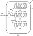
- FIG. 1 is a diagram showing one example of a cabling system in a data center including a distribution rack according to one embodiment of the present invention.
- This cabling system 1 is a system for connecting a plurality of optical fiber-containing cables extending from a telecom company to servers disposed on various floors.
- a bundle of cables C1 from a telecom company extends around a data center 2, and optical fibers contained in the cables C1 are distributed to servers S11 to S34 installed on floors via first to fourth distribution racks 10A, 10B, 10C, 10D.
- FIG. 1 is a diagram showing one example of a cabling system in a data center including a distribution rack according to one embodiment of the present invention.
- This cabling system 1 is a system for connecting a plurality of optical fiber-containing cables extending from a telecom company to servers disposed on various floors.
- a bundle of cables C1 from a telecom company extends around a data center 2, and optical fibers contained in the cables C1 are distributed to servers S11 to S34 installed on
- the first distribution rack 10A connects a part of a bundle of optical fiber-containing cables C1 extending from a telecom company, to two bundles of optical fiber-containing cables C2, C3 each extending from a respective one of the second distribution rack 10B and the third distribution rack 10C.
- the second distribution rack 10B couples the bundle of optical fiber-containing cables C2 extending from the first distribution rack 10A, to optical fiber-containing cables C5 extending from the servers S11 to S14.
- the third distribution rack 10C couples the bundle of optical fiber-containing cables C3 extending from the first distribution rack 10A, to optical fiber-containing cables C6 extending from the servers S21 to S24 and the bundle of optical fiber-containing cables C4 extending from the fourth distribution rack 10D.
- the fourth distribution rack 10D couples the bundle of optical fiber-containing cables C4 extending from the third distribution rack 10C, to optical fiber-containing cables C7 extending from the servers S31 to S34.
- optical fiber cable includes a multi-core cable containing a plurality of core wires, and a few-core cable containing a single core wire.
- optical fibers of the cable C1 extending from the telecom company to the first distribution rack 10A a part of the optical fibers are communicably connected to the servers S11 to S14 via the second distribution rack 10B, and a part of the remaining optical fibers are communicably connected to the servers S21 to S24 via the third distribution rack 10C. Further, the ultimately remaining optical fibers are communicably connected to the servers S31 to S34 via the third distribution rack 10C and the fourth distribution rack 10D. Cables led in each distribution rack and cables led out from each distribution rack are arranged, e.g., under system floors or behind system ceilings.
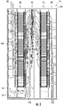
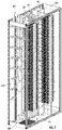
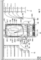
- FIGS. 2 and 3 show the distribution rack according to this embodiment, wherein FIG. 2 is a front view, and FIG. 3 is a perspective view.
- a distribution rack 10 has a frame 90, and comprises, inside the frame 90: a jumper management section 20 provided in a laterally central region thereof; a left termination section 30 and a right termination section 40 provided on both lateral sides of the jumper management section 20; a left cable fixing section 50 and a right cable fixing section 60 each disposed laterally outward of a respective one of the termination sections 30, 40; a left few-core cable fixing section 70 provided on the left side of the bottom of the frame; and a few-core cable management section 80 provided just above the left few-core cable fixing section (cable fixing section) 70.
- the distribution rack 10 is designed to connect an optical fiber of an optical fiber cable inserted from a left top or bottom portion of the frame 90, to an optical fiber of an optical fiber cable inserted from a right top or bottom portion of the frame 90. It may also be configured to connect an optical fiber of an optical fiber cable inserted from a left upper portion of the frame 90 and an optical fiber of an optical fiber cable inserted from a left or right bottom portion of the frame 90, to an optical fiber of an optical fiber cable inserted from a right or left top or bottom portion of the frame 90.
- the left cable fixing section 50 is a region configured to fix a bundle 110 of optical fiber cables 100 inserted from a left region of a top portion of the frame 90, and lead the optical fiber cables toward the left termination section 30 at different height positions.
- a sheath of each of the optical fiber cables is removed, and only a ribbon fiber extends toward the left termination section 30.
- the left termination section 30 is a region configured to connect a fiber core wire extending from the left cable fixing section 50, to one end of a jumper cable 150 or a single-core cable extending from the left few-core cable fixing section 70.
- the one end of the jumper cable 150 is connected to the optical fiber core wire of the optical fiber cable 100 via an adapter.
- the jumper cable 150 is bridged between right and left sides thereof in a sagging state.
- the right cable fixing section 60 is a region configured to fix a bundle 110 of optical fiber cables 100 inserted from a left region of a bottom portion of the frame 90, and lead the optical fiber cables toward the right termination section 40 at different height positions.
- a sheath of each of the optical fiber cables is removed, and only a ribbon fiber extends toward the right termination section 40.
- the right termination section 40 is a region configured to connect a fiber core wire extending from the right cable fixing section 60, to the other end of the jumper cable 150.
- the other end of the jumper cable 150 is connected to the optical fiber core wire via an adapter.
- the left few-core cable fixing section 70 is configured to fix an optical fiber cable inserted from the left region of the bottom portion of the frame 90, and lead the optical fiber cable as a single-core cable toward the left termination section 30 via the jumper management section. It should be noted here that the location of the left few-core cable fixing section 70 is not limited to the bottom portion of the distribution rack 10, but may be any lower portion of the distribution rack 10.
- the few-core cable management section 80 is configured to support the optical fiber extending from the left few-core cable fixing section 70.
- the frame 90 comprises a rectangular-shaped front frame 91, a rear frame 92 having the same shape as that of the front frame 91, and a plurality of cross members 93 ( FIG. 5 ) are bridged between the front frame 91 and the rear frame 92.
- the front frame 91 and the rear frame 92 are held in parallel with a given distance therebetween by the cross members 93.
- the cable fixing section in the distribution rack illustrated in FIG. 2 will be described below. Although the following description will be made about the left cable fixing section, the right cable fixing section also has a bilaterally symmetrical similar configuration.
- FIGS. 4 and 5 are perspective views showing the left cable fixing section illustrated in FIG. 2 , in the distribution rack according to this embodiment, wherein FIG. 4 shows a state in which cables are installed in the left cable fixing section, and FIG. 5 shows a state in which cables are omitted.
- a plurality of bundle 110 of optical fiber cables 100 is inserted into the left cable fixing section 50.
- a plurality of guide members 502A to 502H are arranged side-by-side in an up-down (vertical) direction.
- Each of the guide members 502A to 502H is bridged between and fixed to a pair of vertically-extending pillar members 92A, 92B arranged, in a laterally space-apart relation, inside the rear frame 92 of the frame 90 constituting the distribution rack 10.
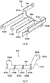
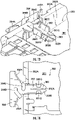
- FIGS. 6 and 7 show the guide member of the cable fixing section in the distribution rack according to this embodiment, wherein FIG. 6 is a perspective view, and FIG. 7 is a side view.
- the guide member 502 comprises: a base part 504 extending in a front-rear direction; an attaching part 508 expending laterally from a rear end of the base part 504; and a plurality of arm parts 510A, 510B, 510C, 510D, 510Z extending from the base part 504.
- the base part 504 is a plate-shaped part whose surface becomes a vertical surface in an attached state and which extends in the front-rear direction.
- the base part 504 has an intermediate area 504C extending in a constant up-down directional width, a front end area 504B extending obliquely upwardly with respect to the intermediate area 504C, and a rear end area 504A having an up-down directional width expanding upwardly.
- the attaching part 508 is a plate-shaped part whose surface becomes vertical in the attached state and which extends laterally inwardly from an upper area of the rear end area 504A.
- Each of the arm parts 510A, 510B, 510C, 510D, 510Z is a plate-shaped part whose surface becomes a vertical surface in the attached state and which extends laterally outwardly from the base part 504. Front-rear directional intervals between adjacent ones of the arm parts 510A, 510B, 510C, 510D, 510Z are set to become approximately equal. Further, in all the guide members 502 of the left cable fixing section 50, the front-rear directional intervals between adjacent ones of the arm parts 510 are set to be equal to each other. It is to be understood that the interval may be arbitrarily set depending on the diameter of a cable to be routed or the number of the cables.
- the frontwardmost arm part 504A is connected to a front end of the front end area 504B.
- Each of upper and lower edges of the frontwardmost arm part 504A is formed in a wave shape with a continuous undulation.
- the second-frontwardmost arm part 510B is connected to a boundary between the intermediate area 504C and the front end area 504B.
- Each of upper and lower edges of the second-frontwardmost arm part 504B is formed in a wave shape with a continuous undulation.
- the rearwardmost arm part 510Z extends laterally outwardly from a lower area of the rear end area 504A of the base part 504.
- receiving spaces 512A, 512b, 512C, 512Z each opened laterally outwardly are formed between adjacent ones of the arm parts 510A, 510B, 510C, 510D, 510Z.
- Each of the receiving spaces 512A, 512b, 512C, 512Z is opened laterally.
- the first to eighth guide members 502 are attached to the left cable fixing section 50 at approximately even intervals in the downward direction from the top.
- Each of the guide members 502 is fixed by screwing distal ends of the rearwardmost arm part 510Z and the attaching part 508 to the pair of pillar members 92A, 92B, respectively.
- the number of the arm parts 510 in a lower one of the guide members 502 is set to be equal to or less than that in an upper one of the guide members 502.
- each of the first guide member 502A and the second guide member 502B has eight arm parts 510
- the third guide member 502C, the fourth guide member 502D and the fifth guide member 502E have, respectively, seven arm parts 510, six arm parts 510 and five arm parts 510
- the sixth guide member 502F, the seventh guide member 502G and the eighth guide member 502H have, respectively, four arm parts 510, three arm parts 510 and two arm parts 510.
- optical fiber cables extend downwardly from the top of the left cable fixing section 50, while being aligned to form a plurality of rows in the right-left (lateral) direction and a plurality of columns in the front-rear direction.
- the optical fiber cables 100 are received in each of the receiving spaces 512 in a state in which they are aligned to form one or two columns in the front-rear direction and three to five rows in the right-left direction.
- Each of the optical fiber cables 100 is received in up-down directionally corresponding ones of the receiving spaces 512 of the guide members 502.
- the rearwardmost column of optical fiber cables 100 are received in and guided by the rearwardmost receiving spaces 512Z of the first to eighth guide members 502A to 502H, and fixed to the eighth guide member 502H, wherein a sheath of each of them is peeled off at a position below the eighth guide member 502H.
- the second-and third-rearwardmost columns of optical fiber cables 100 are received in and guided by the second-rearwardmost receiving spaces 512 of the first to seventh guide members 502A to 502G, and fixed to the seventh guide member 502G, wherein a sheath of each of them is peeled off at a position below the seventh guide member 502G.
- the fourth-and fifth-rearwardmost columns of optical fiber cables 100 are received in and guided by the third-rearwardmost receiving spaces 512 of the first to sixth guide members 502Ato 502F, and fixed to the sixth guide member 502F, wherein a sheath of each of them is peeled off at a position below the sixth guide member 502F.
- the sixth-and seventh-rearwardmost columns of optical fiber cables 100 are received in and guided by the fourth-rearwardmost receiving spaces 512 of the first to fifth guide members 502A to 502E, and fixed to the fifth guide member 502E, wherein a sheath of each of them is peeled off at a position below the fifth guide member 502E.
- the eighth-and ninth-rearwardmost columns of optical fiber cables 100 are received in and guided by the fifth-rearwardmost receiving spaces 512 of the first to fourth guide members 502A to 502D, and fixed to the fourth guide member 502D, wherein a sheath of each of them is peeled off at a position below the fourth guide member 502D.
- the tenth-and eleventh-rearwardmost columns of optical fiber cables 100 are received in and guided by the sixth-rearwardmost receiving spaces 512 of the first to third guide members 502A to 502C, and fixed to the third guide member 502C, wherein a sheath of each of them is peeled off at a position below the third guide member 502C.
- the twelfth-and thirteenth-rearwardmost columns of optical fiber cables 100 are received in and guided by the seventh-rearwardmost receiving spaces 512 of the first and second guide members 502A, 502B, and fixed to the second guide member 502B, wherein a sheath of each of them is peeled off at a position below the second guide member 502B.
- FIG. 8 is a perspective view showing a state in which an optical fiber cable is fixed to the guide member illustrated in FIG. 6 .
- FIG. 8 for the purpose of illustration, only one of a front column of optical fiber cables 100A and one of a rear column of optical fiber cables 100B, in the frontwardmost receiving space 512A, are shown, and the remaining optical fiber cables 100 are omitted.
- the optical fiber cable 100 comprises: an optical fiber core wire 120 obtained by covering a bare fiber made of glass and composed of a core and a clad, with UV coating or the like; and a sheath (outer covering) surrounding one or more optical fiber core wires.
- the optical fiber core wire is used to form a cable, in the form of a tape core wire (ribbon fiber) obtained by forming a plurality of optical fiber core wires aligned side-by-side, into a tape-like shape.
- Each of the front column of optical fiber cables 100A among optical fiber cables 100 received in the frontwardmost receiving space 512A is fixed to the frontwardmost arm part 510A by a binding band 520.
- Each of the upper and lower edges of the frontwardmost arm part 510A is formed with an undulation, as mentioned above.
- a sheath 115 of each of the front column of optical fiber cables 100A is removed at a position below the frontwardmost arm part 510A, so as to expose the ribbon fiber 120.
- Each of the rear column of optical fiber cables 100B among the optical fiber cables 100 received in the frontwardmost receiving space 512A is fixed to the second-frontwardmost arm part 510B by a binding band 520.
- Each of the upper and lower edges of the second-frontwardmost arm part 510B is formed with an undulation, and thus, during the fixing, it is possible to restrain the optical fiber cable 100B from moving laterally.
- a sheath 115 of each of the front column of optical fiber cables 100B is removed at a position below the second-frontwardmost arm part 510B, so as to expose the ribbon fiber 120.
- FIG. 8 shows a single-core optical fiber cable, a multi-core optical fiber cable can be fixed in a similar manner.
- the ribbon fiber 120 of the optical fiber cable 100 whose sheath had been peeled off in the above manner is led to the cassettes 320 of the left termination section 30 located at approximately the same height position as that of the ribbon fiber 120.
- the first to eighth guide members 502 of the left cable fixing section 50 has the arm parts 510A, 510B, 510C, 510D, 510Z, and the receiving spaces 512A, 512b, 512C, 512Z each opened laterally outwardly are formed between adjacent ones of the arm parts.
- the optical fiber cables 100 when optical fiber cables 100 is arranged in a single column in the front-rear direction, the optical fiber cables 100 can be fixed to the frontwardmost arm part 510A, and, when optical fiber cables 100 are arranged in a plurality of columns in the front-rear direction, the optical fiber cables 100 can be fixed to the frontwardmost arm part 510A and the second-frontwardmost arm part 510B, in two groups, and thus, even in a case where optical fiber cables 100 are arranged in high density, it is possible to easily fix the optical fiber cables 100.
- the frontwardmost arm part 510A is provided above the second-frontwardmost arm part 510B.
- the columns of optical fiber cables 100 can be fixed, respectively, to the arm parts at different height positions.
- the cables are fixed to the second-frontwardmost arm part 510B, it is possible to prevent the second-frontwardmost arm part 510B from hiding behind the frontwardmost arm part 510A, thereby improving working efficiency of the fixing operation.
- each of the upper and lower edges of the frontwardmost arm part 510A and the upper and lower edges of the second-frontwardmost arm part 510B is formed with an undulation. This makes it possible to prevent an optical fiber cable 100 from moving laterally even when fixing the optical fiber cable 100 using the binding band 520 or the like. It should be noted here that such an undulation may be provided in only one of the upper and lower edges, or may be provided in one of the frontwardmost arm part 510A and the second-frontwardmost arm part 510B.
- the first to eighth guide members 502 are configured such that a lower one thereof is gradually reduced in terms of the number of arm parts. This makes it possible to fix a front-side column of optical fiber cables 100 to the arm part on a relatively upper side of the cable fixing section, and fix a rear-side column of optical fiber cables 100 to the arm part on a relatively lower side of the cable fixing section, thereby facilitating the fixing operation for optical fiber cables 100.
- FIG. 9 is an enlarged perspective view showing the configuration of the left termination section in the distribution rack illustrated in FIG. 2 .
- FIG. 10 is a perspective view showing the cassette constituting the left termination section illustrated in FIG. 9 .
- FIGS. 11 and 12 show the cassette of the left termination section illustrated in FIG. 9 and the vicinity thereof, wherein FIG. 11 shows a state in which the cassette is retracted, and FIG. 12 shows a state in which the cassette is pulled out such that a jumper cable-side connector can be attached/detached.
- the left termination section comprises: a rail frame 310 fixed to the frame 90 with a given lateral distance therebetween; a plurality of cassettes 320 supported by the rail frame 310; a lateral guide member 330 provided at a position front of the rail frame 310 on the side of the left cable fixing section 50; a core wire fixing portion (optical fiber cable fixing member) 340 disposed on the lateral side of the lateral guide member 330; and a jumper cable fixing portion 350 disposed front of a right portion of the rail frame 310 on the side of the jumper management section 20.
- the rail frame 310 is composed of a plurality of pairs of left and right rails 310A, 310B arranged with a given distance therebetween in the up-down direction.
- Each of the left and right rails 310A, 310B is composed of a member formed to extend in the front-rear direction, wherein a groove is formed in each of opposed surfaces of the rails 310A, 310B to extend in the front-rear direction.
- Each of the cassettes 320 is made of metal such as stainless steel, resin or the like, and comprised a cassette body 360, and a swingable portion 370 swingably attached to a front end of the cassette body 360.
- the cassette 320 is configured such that the after-mentioned sliders 363A, 363B thereof are supported, respectively, by the rails 310A, 310B, slidably in the front-rear direction.
- the cassette 320 can selectively take a detached position where it is detached from the rail frame 310, a pullout position where it is pulled out while being supported by the rails 310A, 310B, and a retracted position where it is retracted while being supported by the rails 310A, 310B.
- optical fibers are routed inside the cassette 320, it is desirable to conduct such an operation in a state in which the cassette 320 is taken out from the rail frame 310.
- the cassette body 360 comprises: a bottom plate part 361; a pair of sidewall parts 362A, 362B each provided to stand from a respective one of opposed lateral edges of the bottom plate part 361; and a rear wall part 363 provided to stand from a rear edge of the bottom plate part 361.
- the bottom plate part 361 is a region formed in an approximately rectangular plate shape.
- the pair of sidewall parts 362A, 362B are standingly provided to extend in the front-rear direction, respectively, along the opposed lateral side edges of the bottom plate part 361.
- a front-rear directional length of each of the sidewall parts 362A, 362B is greater than that of the bottom plate part 361, and a part of each of the sidewall parts 362A, 362B extends frontwardly beyond the bottom plate part 361.
- a pair of slide parts 363A, 363B are provided to extend, respectively, from upper edges of the sidewall parts 362A, 362B, laterally outwardly.
- Each of the slide parts 363A, 363B is formed over the entire front-rear directional length of a corresponding one of the sidewall parts 362A, 362B to have an approximately constant width.
- the pair of the sidewall parts 362A, 362B are formed, respectively, with two opening (first and second introduction ports) 364A, 364B at positions on the rear side of the after-mentioned adapters 322.
- the opening 364A on the side of the left cable fixing section 50 functions as an opening for introducing a core wire of an optical fiber cable 100 therethrough, wherein a core wire guide member 380 is attached thereto.
- the opening 364B on the side of the jumper management section 20 functions as a region for attaching a jumper cable supporting member 326 thereto.
- the pair of the sidewall parts 362A, 362B are formed, respectively, with cutouts 365A, 365B opened upwardly at front ends of the sidewall parts 362A, 362B.
- the rear wall part 363 is provided to extend between the pair of the sidewall parts 362A, 362B.
- An adapter retaining portion 322A is provided along a front edge of the bottom plate part 361 swingably in the front-rear direction, and a plurality of adapters 322 are attached to the adapter retaining portion 322A such that they are arranged side-by-side in the lateral direction over the entire width of the bottom plate part 361.
- a part of the bottom plate part 361 facing the core wire housing space 366 is formed with a left front-side guide protrusion 361A, a left intermediate guide protrusion 361B, a left rear-side guide protrusion 361C, a right front-side guide protrusion 361D, a right intermediate guide protrusion 361E, and a right rear-side guide protrusion 361F.
- Each of these guide protrusions 361A, 361B, 361C, 361D, 361E, 361F are composed of a plate-shaped member provided to stand perpendicularly to the bottom plate part 361.
- Each of the left front-side guide protrusion 361A and the right front-side guide protrusion 361D is located rearward of a respective one of the openings 364A, 364B.
- Each of the left front-side guide protrusion 361A and the right front-side guide protrusion 361D has a rear part formed in a plate shape extending in the front-rear direction, and a front part extending frontwardly while curving toward a central region of the cassette.
- Each of the left rear-side guide protrusion 361C and the right rear-side guide protrusion 361F is located around a respective one of two rear corners of the bottom plate part 361.
- Each of the left rear-side guide protrusion 361C and the right rear-side guide protrusion 361F has a front part formed in a plate shape extending in the front-rear direction, and a rear part extending rearwardly while curving toward the central region of the cassette.
- the left intermediate guide protrusion 361B is located between the rear part of the left front-side guide protrusion 361A and the front part of the left rear-side guide protrusion 361C, in a state in which they are aligned with each other in the front-rear direction.
- the right intermediate guide protrusion 361E is located between the rear part of the right front-side guide protrusion 361D and the front part of the right rear-side guide protrusion 361F, in a state in which they are aligned with each other in the front-rear direction.
- the swingable portion 370 comprises: a bottom plate part 371; a pair of sidewall parts 372 each provided to stand along a respective one of opposed lateral edges of the bottom plate part 371; a front face-forming part 373 provided to stand along a front edge of the bottom plate part 371 perpendicularly to the bottom plate part 371; and a fold-back part 374 provided to extend rearwardly from an upper edge of the front face-forming part 373.
- the swingable portion 370 is configured such that rear ends of the pair of sidewall parts 372 is pivotally connected, respectively, to the sidewall parts 362A, 362B of the cassette 320 at positions frontward of the adapters 322.
- the swingable portion 370 is configured to be swingable between a state in which the bottom plate part 371 is set horizontally and located on the same plane as that of the bottom plate part 361 of the cassette 320, and a state in which the bottom plate part 371 is tilted obliquely downwardly and frontwardly.
- the pair of sidewall parts 372, the front face-forming part 373, the fold-back part 374 and the adapters 322 surroundingly define a jumper housing space 375.
- FIGS. 13 and 14 enlargedly show the core wire guide member of the cassette illustrated in FIG. 10 and the vicinity thereof, wherein FIG. 13 is a perspective view, and FIG. 14 is a top plan view.
- the core wire guide member 380 has a base end part 382, and a widened part 384 extending from the base end part 382 toward the lateral direction while gradually expanding in the front-rear direction.
- the base end part 382 is a region in which it extends in an approximately constant width and which is located inside the core wire housing space 366 in an attached state thereof.
- the base end part 382 is formed with a slit 382A extending from a top end of the base end part 382 along a widthwise center line thereof.
- the top end 382 B of the base end part 382 is formed to have a width larger than that of a part of the base end part 382 on the side of the widened part 384.
- a pair of guide walls 382C are formed, respectively, along opposed edges of the part of the base end part 382 on the side of the widened part 384.
- the widened part 384 is formed such that a front-rear directional width thereof is expanded toward a laterally outward direction.
- a pair of guide walls 384A are formed, respectively, along front-rear directionally opposed edges of a widening part of the widened part 384.
- the pair of guide walls 384A extend in a laterally frontward direction and in a laterally rearward direction, respectively.
- Each of the guide walls 384A is formed in a curved shape which is convex toward a front-rear directionally central region of the widened part 384.
- the widened part 384 is provided with a pair of arms 384B each extending thereabove in a covering manner.
- the bottom plate part 361 has a pair of holding protrusions 361G formed in the vicinity of the opening 364A such that they are opposed to each other in the front-rear direction.
- the holding protrusions 361G stand from the bottom plate part 361 and then bend such that they extend toward each other.
- the base end part 382 is inserted into the opening 364A from the outside, and then fitted between the pair of holding protrusions 361G, the base end part 382 is placed in a state in which the top end 382B thereof is located inside the holding protrusions 361G, and an upper surface thereof is covered by the pair of holding protrusions 361G, whereby the core wire guide member 380 can be fixed to the cassette body 360.
- a part of the bottom plate part 361 corresponding to the front-rear directionally intermediate region of the core wire housing space 366 is formed with the after-mentioned sleeve retaining part 3611, and a branching portion retaining part 361H for retaining the after-mentioned branching portion 130.
- the branching portion retaining part 361H is provided on both lateral sides of the sleeve retaining part 3611.
- the jumper cable supporting member 390 has a member body 392 located on a laterally outward side of the cutout 365B, and an attaching part 394 extending from the member body 392 along the sidewall part 362B.
- the attaching part 394 extends in the front-rear direction along an outer surface of the sidewall part 362B, and a distal end thereof is bent toward the cassette 320.
- the distal end of the attaching part 394 is formed in a similar shape to that of the base end part 382 of the core wire guide portion 324, and the jumper cable supporting member 390 is fixed to the cassette body 360 by inserting the attaching part into the opening 364B.
- the member body 392 In an attached state, the member body 392 is located beside the cutout 365B.
- the member body 392 has: a base plate part 392A extending toward the jumper management section 20; a standing part 392B standing upwardly from an edge of the base plate part 392A on the side of the jumper management section 20; and a fold-back part 392C extending from an upper edge of the standing part 392B toward the swingable portion 370.
- the slide parts 363A, 363B of the cassette body 360 are set, respectively, in the grooves of the rails 310A, 310B, so as to allow the cassette 320 to be held movably in the front-rear direction.
- the cassette 320 can selectively take the retracted position where it is pushed rearwardly, the pullout position where it is pulled frontwardly, and the detached position where it is detached from the rail frame 310. In the pullout position, it is possible to swing the swingable portion 370 with respect to the cassette body 360.
- this operation When laying out a ribbon fiber 120 of an optical cable 100, this operation may be conducted in a state in which the cassette 320 is set in the detached position, and, when laying out a jumper cable 150, this operation may be conducted in a state in which the cassette 320 is set in the pullout position, and further the swingable portion 370 is swung downwardly.
- the lateral guide member 330 In a state in which the cassette 320 is set in the retracted position, the lateral guide member 330 is disposed laterally outward of and adjacent to the core wire guide member 380.
- the lateral guide member 330 extends vertically with a constant horizontal sectional shape.
- the lateral guide member 330 includes: a flat surface part 332 extending along a top end of the widened part 384 of the core wire guide member 380 in the state in which the cassette 320 is set in the retracted position; and a curved surface part 334 arcuately extending from a front end of the flat surface part 332 to the core wire fixing portion 340.
- a front end of the flat surface part 332 is approximately aligned, in the front-rear direction, with a front end of the widened part 384 of the core wire guide member 380.
- the core wire fixing portion 340 is provided rearward of and continuous with the curved surface part 334 of the lateral guide member 330.
- the core wire fixing portion 340 has a plurality of slits 342 provided at given intervals and each opened laterally, frontwardly and rearwardly in a horizontal direction.
- the jumper cable fixing portion 350 is disposed rearward of the jumper cable supporting member 390.
- the jumper cable fixing portion 350 has a plurality of slits 352 provided at given intervals and each opened laterally, frontwardly and rearwardly in a horizontal direction. Each of the slits 352 is opened on the front and rear side of the jumper cable fixing portion 350 and the lateral side of the jumper cable fixing portion 350 facing the jumper management section 20.
- a ribbon fiber 120 of an optical fiber cable 100 whose sheath had been peeled off in the left cable fixing section 50 is led to extend toward the core wire fixing portion 340, and clamped by one of the slits 342 of the core wire fixing portion 340, so that it is fixed to the core wire fixing portion 340.
- one of the slits 342 of the core wire fixing portion 340 to which the ribbon fiber 120 is fixed has a height position corresponding to that of one of the cassettes 320 into which the ribbon fiber 120 is subsequently introduced.
- the ribbon fiber 120 fixed to the core wire fixing portion 340 is led along the lateral guide member 330, and further lead between the pair of guide walls 384A of the widened part 384 of the core wire guide member 380. Then, the ribbon fiber 120 is introduced from the opening 364A of the cassette 320 into the core wire housing space 366. As shown in FIGS. 13 and 14 , after the ribbon fiber 120 introduced into the core wire housing space 366 extends rightwardly, it is lead rearwardly along the right front-side guide protrusion 361D. Then, after extending rearwardly, the ribbon fiber 120 is led laterally outwardly (leftwardly) by the right rear-side guide protrusion 361F.
- the ribbon fiber 120 is led frontwardly by the left rear-side guide protrusion 361C. Then, after extending frontwardly, the ribbon fiber 120 is led laterally inwardly (rightwardly) by the left front-side guide protrusion 361A. Then, after extending laterally inwardly, the ribbon fiber 120 is led rearwardly by the right front-side guide protrusion 361D. Then, after extending rearwardly, the ribbon fiber 120 is led toward a central region of the core wire housing space 366 by the right rear-side guide protrusion 361F, and connected to a tape core wire 122 from a fan-out branching portion 130 by a fusion sleeve 132.
- the fan-out branching portion 130 is configured to divide the tape core wire 122 connected to the ribbon fiber 120 by the fusion sleeve 132, into a plurality of single-core fibers 140.
- Each of the single-core fibers 140 is surrounded by a protective tube or a sheath, and a connector 140A is attached to an end thereof.
- Each of the single-core fibers 140 extends frontwardly from the branching portion 130, and the connector 140A at the end of the single-core fiber 140 is connected to one of the adapters 322 from the rear side of the adapter 322.
- a connector 152 of a jumper cable 150 is connected to one of the adapters 322 from the front side of the adapter 322.
- a jumper cable 150 is led to extend from the jumper management section 20, and clamped by one of the slits 342 of the jumper cable fixing portion 350 located at a height position corresponding to that of one of the cassettes 320 to which the jumper cable 150 is introduced. Then, the jumper cable 150 is introduced from the jumper cable fixing portion 350 into the jumper cable supporting member 390 from the rear side of the jumper cable supporting member 390.
- the jumper cable 150 is guided into the cutout 365B while being held by the standing part 392B and the fold-back part 392C of the jumper cable supporting member 390. Then, the jumper cable 150 is guided from the cutout 365B into the jumper housing space 375, and the connector at the end thereof is connected to one of the adapter 322 from the front side of the adapter 322.
- the cassette 320 When laying out the ribbon fiber 120 within the cassette 320, the cassette 320 is set in the detached position where it is moved frontwardly and detached, to conduct this operation.
- the ribbon fiber 120 is introduced from the opening 364A of the cassette 320 into the core wire housing space 366. Then, the ribbon fiber 120 introduced into the core wire housing space 366 is led to go around the core wire housing space 366 as many times as needed, along the right front-side guide protrusion 361D, the right rear-side guide protrusion 361F, the left rear-side guide protrusion 361C and the left front-side guide protrusion 361A, and further bent toward the central region of the core wire housing space 366, along the right front-side guide protrusion 361D and the right rear-side guide protrusion 361F.
- the ribbon fiber 120 is connected to the tape core wire 122, and reinforced by the fusion sleeve 132.
- the fan-out branching portion 130 and the single-core fibers 140 and the tape core wire 122 connected to the branching portion 130 may be preliminarily attached to the cassette 320, and the connectors 140A of the single-core fibers 140 may be preliminarily connected to the adapters.
- the cassette 320 is attached to the rail frame 310, and set in the pullout position. Then, in this pullout position, the ribbon fiber 120 is disposed to extend along the lateral guide member 330 such that no excessive bending is applied thereto, and inserted in one of the slits 342 of the core wire fixing portion 340.
- the ribbon fiber 120 can be led to extend from the core wire fixing portion 340 along an outer surface of the lateral guide member 330, and further guided to the opening 364A along the rear guide wall 384A of the core wire guide member 380. This makes it possible to prevent the ribbon fiber 120 from undergoing excessive bending.
- this operation is conducted in a state in which the cassette 320 is moved frontwardly, and further the swingable portion 370 is swung such that it is tilted obliquely downwardly with respect to the cassette body 360.
- the jumper cable 150 extending from the jumper management section 20 is inserted in one of the slits 352 of the jumper cable fixing portion 350 corresponding to one of the cassettes 320 to which the jumper cable 150 is laid out. Then, the jumper cable 150 is guided frontwardly from the jumper cable fixing portion 350, and led to the cutout 365B while being placed on the jumper cable supporting member 390. In this process, the jumper cable 150 is surrounded by a restraint portion 392D composed of the base plate part 392A, the standing part 392B and the fold-back part 392C of the jumper cable supporting member 390, so that it is possible to hold the jumper cable 150 so as not to spread in a height direction and in the lateral direction.
- the connector 152 at the end of the jumper cable 150 is connected to one of the adapters 322 from the front side of the adapter 322. Then, after all of the jumper cables 150 to be housed in this cassette 320 are laid out in the same manner, the swingable portion 370 is swung such that it becomes parallel to the cassette body 360. In this process, the jumper cable 150 is disposed such that it is surrounded by a restraint portion 376 composed of the bottom plate part 371, the front face-forming part 373 and the fold-back part 374. This allows the jumper cable 150 to be housed in the jumper housing space 375 so as not to spread in the up-down direction.
- the cassette 320 is pushed and returned to the retracted position.
- the ribbon fiber 120 is guided such that it is bent along the front guide wall 384A of the core wire guide member 380, so that it is possible to prevent the ribbon fiber 120 from undergoing excessive bending.
- the core wire guide member 380 is provided in the above manner. This, when the cassette 320 is set in a cabling position where it is pulled out frontwardly, the ribbon fiber 120 is guided by the lateral guide member 330 and the rear guide wall 384A, and, when the cassette 320 is set in the retracted position where it is pushed rearwardly, the ribbon fiber 120 is guided by the lateral guide member 330 and the front guide wall 384A, so that it is possible to prevent excessive bending.
- the core wire guide member 380 is formed as a separate component from the cassette 320. Alternatively, it may be formed integrally with the cassette 320.
- the core wire guide member 380 having the front and rear guide walls 384A each formed in a curved shape which is convex toward a guide space defined therebetween is provided in the opening 364A for introduction of the ribbon fiber 120, so that it is possible to prevent the ribbon fiber 120 from undergoing excessive bending, even when the cassette 320 is moved in the front-rear direction.
- the core wire guide member 380 has the arms 384B extending above the guide space, so that, even when the cassette 320 is moved in the front-rear direction, the arms 384B can prevent the ribbon fiber 120 from bending upwardly, thereby preventing the ribbon fiber 120 from undergoing excessive curvedness or up-down directional flexure.
- the lateral guide member 330 is provided beside the sidewalls 362A of the plurality of cassettes 320, and formed in a frontwardly curved shape in plan view, wherein the ribbon fiber 120 is introduced into the opening 364A while being in contact with along a side surface of the lateral guide member 330. This makes it possible to prevent a portion of the ribbon fiber 120 outside the cassette 320 from undergoing excessive curvedness
- the lateral guide member 330 is disposed such that a frontwardmost area of a front surface of the lateral guide member 330 is located rearward of the opening 364A of the cassette 320 when the cassette 320 is moved to a frontwardmost position, and is located frontward of the opening 364A of the cassette 320 when the cassette 320 is moved to a rearwardmost position. This makes it possible to suppress the movement of the portion of the ribbon fiber 120 outside the cassette 320 due to the movement of the cassette 320.
- the core wire fixing member 340 capable of fixing a part of the ribbon fiber 120 is further provided beside and rearward of the lateral guide member 330. This makes it possible to reliably guide the ribbon fiber 120 along the lateral guide member 330.
- the cassette 320 is formed with the jumper housing space 375 located frontward of the adapter 322 and capable of housing an end portion of the jumper cable 150
- the right sidewall 362B of the cassette 320 is formed with the cutout 365B located frontward of the adapter 322 and capable of introducing the end portion of the jumper cable 150 into the jumper housing space 375 therethrough.
- the jumper cable 150 can be housed in a front region of the cassette 320, so that it is possible to isolate the ribbon fiber 120 from the jumper housing space, thereby preventing interference between the ribbon fiber 120 and the jumper cable 150.
- the cassette 320 is bilaterally symmetrical, wherein the cassette 320 has the opening 364B formed in the right sidewall 362B at a position symmetrically opposed to the opening 364A, and wherein the opening 364B is provided with the jumper cable supporting member 390 configured to guide the jumper cable 150.
- the cassette 320 can be used to handle both cases where the ribbon fiber 120 is introduced from the right side and from the left side. Further, the introduction of the ribbon fiber 120 and the installation of the jumper cable supporting member can be performed using the openings 364A, 354B formed bilaterally symmetrically.
- the jumper cable supporting member 390 has the restraint portion 392D configured to restrain the jumper cable 150 in the up-down direction.
- the restraint portion 392D can restrain the jumper cable 150 in the up-down direction, so that it is possible to prevent the jumper cable from bending in the up-down direction, even when the cassette 320 is moved in the front-rear direction.
- the cassette 320 has the swingable portion 370 located on a front side thereof to define the jumper housing space 375 and configured to be swingable about a swing axis extending in the lateral direction, wherein the swingable portion 370 has the restraint portion 376 configured to restrain the jumper cable 150 in the up-down direction.
- the swingable portion 370 can be swung to facilitate housing the jumper cable 150 in the jumper housing space 375, and to prevent the jumper cable 150 from getting out of the jumper housing space 375, even when the cassette 320 is moved in the front-rear direction.
- the jumper cable fixing portion 350 capable of fixing a part of the jumper cable 150 is provided beside the second sidewalls 362B of the plurality cassettes 320. This makes it possible to, even when the cassette 320 is moved, prevent the jumper cable 150 from moving along with the movement of the cassette 320.
- FIG. 15 is a front view enlargedly showing the jumper management section of the distribution rack illustrated in FIG. 2 .
- FIG. 16 is a perspective view showing a cable manager constituting the jumper management section illustrated in FIG. 15 .
- the jumper management section 20 is composed of two groups of cable managers 210, which are arranged bilaterally symmetrically. As shown in FIG. 16 , each of the cable managers 210 comprised a center member 212 extending like a rod, and a plurality of partition plates 214 provided on the center member 212 at given intervals.
- the center plate 212 has a base end fixed to a rear part of the frame 90, and extends frontwardly in a horizontal direction.
- the center member 212 is formed in an approximately semicircular shape in cross-section, and disposed at a tilt such that one lateral end thereof on the side of a lateral center of the jumper management section 20 is located lower than the other lateral end.
- the plurality of partition plates 214 are provided in evenly spaced-apart relation from a front end of the center member 212.
- Each of the partition plates 214 has an outer shape approximately similar to the cross-sectional shape of the center member 212, and annularly surrounds the entire circumference of the center member 212.
- Concave areas 216 are formed between adjacent ones of the partition plates 214 and between a rearwardmost one of the partition plates 214 and the frame.
- the cable managers of the left group are arranged side-by-side such that they gradually spread leftwardly toward a downward direction
- the cable managers of the right group are arranged side-by-side such that they gradually spread rightwardly toward the downward direction. That is, the right and left groups of cable managers are arranged such that the overall width thereof gradually increases toward the downward direction.
- a jumper cable 150 is bridged between laterally corresponding two of the right and left groups of cable managers 210 in a sagging state, and a left end and a right end thereof are introduced, respectively, into the left termination section 30 and the right termination section 40.
- Jumper cables 150 extending from two or more of the plurality of cassettes 320 are hung on each of the jumper cables 210.
- six jumper cables 150 extending from the uppermost and second-to sixth-uppermost cassettes 320 are hung on the uppermost jumper manager 210 in FIG. 16 .
- the jumper cables 150 each corresponding to a respective one of the cassette 320 are received, respectively, in different ones of the concave areas 216, for example, such that a jumper cable 150 to be connected to the uppermost cassette 320Ais received in the frontmost concave area 216, and a jumper cable 150 to be connected to the second-uppermost cassette 320B is received in the second-frontmost concave area 216.
- a plurality of jumper cables 150 are bridged between the cassettes 320 of the left termination section 30 and the cassettes 320 of the right termination section 40.
- the left few-core cable fixing section of the distribution rack illustrated in FIG. 2 will be described below.
- FIG. 17 is a perspective view showing a base frame of the left few-core cable fixing section of the distribution rack illustrated in FIG. 2 .
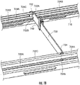
- FIG. 18 is a perspective view enlargedly showing the left few-core cable fixing section of the distribution rack illustrated in FIG. 2 , in a state in which a few-core cable is fixed thereto.
- FIG. 19 shows only one slidable support bar 730 for the purpose of illustration.
- Examples of a few-core cable 160 to be fixed to the left few-core cable fixing section include: a cable having the same structure as that of a jumper cable obtained by covering a single fiber core wire with a circular external sheath, together with tensile fibers such as aramid fibers; a cable (eyeglasses type) in which a plurality of the above cables are arranged in parallel wherein central portions thereof are coupled to each other; and a cable obtained by covering one or two pieces of the round-type cables with an outer sheath, together with one or more pieces of tensile members.
- the left few-core cable fixing section (cable fixing section) 70 comprises: a rectangular-shaped base frame 710; a front rail 722 and a rear rail 724 each held along a respective one of a front edge and a rear edge of the base frame 710; and a slidable support bar 730 bridged between the front rail 722 and the rear rail 724.
- Each of the front rail 722 and the rear rail 724 has laterally opposite ends supported such that a gap is formed with respect to the base frame in a height direction thereof.
- Each of the front rail 722 and the rear rail 724 is formed by bending a plate into a cross-sectionally angular-C shape which has: a vertical wall 722A, 724A extending vertically; a lower wall 724B extending inwardly in the front-rear direction from a lower edge of the vertical wall 722A, 724A; an upper wall 722C, 724C extending inwardly in the front-rear direction from an upper edge of the vertical wall 722A, 724A.
- the slidable support bar 730 is formed by bending opposite ends 732, 734 of a plate perpendicularly in one direction. Each of the opposite ends of the slidable support bar 730 is formed with a pair of slits 732A, 732B; 734A, and the edges of the upper walls 722C, 724C and the lower walls 722B, 724B of the front rail 722 and the rear rail 724 are inserted, respectively, in the slits 734A, 732A, 732B. In this way, the slidable support bar 730 is held laterally slidably along the front rail 722 and the rear rail 724, in a state in which the surface thereof extend in the up-down direction and in the front-rear direction.
- the left few-core cable fixing section is configured such that each of the front rail 722 and the rear rail 724 extends in the right-left (lateral) direction, and the slidable support bar 730 extends in the front-rear direction.
- the left few-core cable fixing section may be configured such that a pair of rails are arranged to extend in the front-rear direction, and the slidable support bar is bridged between the pair of rails in the right-left direction, such that it is movable along the pair of rails in the front-rear direction. That is, after arranging a pair of rails in parallel, the slidable support bar may be disposed in a direction intersecting the rails.
- the left few-core cable fixing section 70 also comprises a clip member 740.
- FIGS. 19 and 20 are perspective views showing the clip member to be used in the left few-core cable fixing section, wherein FIG. 19 shows a state in which a cover thereof is opened, and FIG. 20 shows a state in which the cover is closed to fix an optical fiber cable thereto.
- the clip member 740 is formed of an elastic resin or the like, and comprises a clip-like attaching portion 750 and a cable retaining portion 760.
- the attaching portion 750 has an H shape in cross-section, and comprises an obverse wall part 752, a reverse wall part 754, and a pivotal connection part 756.
- Each of the obverse wall part 752 and the reverse wall part 754 has an up-down directionally elongate shape.
- the obverse wall part 752 and the reverse wall part 754 are connected together by the pivotal connection part 756 extending between opposed surfaces of the wall parts at a position upward of an up-down directionally midpoint thereof.
- a pawl 752A is formed on an inner surface of a lower end of the obverse wall part 752 to extend laterally.
- the pawl may be provided on the reverse wall part 752, or may be provided on each of the obverse wall part 752 and the reverse wall part 754.
- the obverse wall part 752 and the reverse wall part 754 can be swung about the pivotal connection part 756 so as to expand a gap between lower ends of the obverse wall part 752 and the reverse wall part 754.
- a deformed shape returns to the original state, so that the gap between lower ends of the obverse wall part 752 and the reverse wall part 754 is closed.
- the attaching portion has a clip-like configuration.
- clip-like configuration means a configuration in which a pair of members (the obverse wall part 752 and the reverse wall part 754) are provided swingably about a connection part (the pivotal connection part 756), wherein the slidable support bar 730 can be clamped by the pair of members.
- the attaching portion 750 can be attached to the slidable support bar 730 by: pinching the upper ends of the obverse wall part 752 and the reverse wall part 754 to open the lower ends of the obverse wall part 752 and the reverse wall part 754; disposing the attaching portion 750 such that the slidable support bar 730 is located between the obverse wall part 752 and the reverse wall part 754; and closing the lower ends of the obverse wall part 752 and the reverse wall part 754.
- the cable holding portion 760 comprises a pair of first and second sidewall parts 762, 764 each extending in the up-down direction, and a cover part 766 swingably connected to the first sidewall part 762.
- Each of the first and second sidewall parts 762, 764 is provided on an outer surface of the obverse wall part to stand in a direction perpendicular to the outer surface, and extend in the up-down direction.
- One of opposed side edges of the cover part 766 is connected along a distal edge of the first sidewall part 762, so as to allow the cover part 766 to be swung about this connection area extending in the up-down direction.
- a pawl 766A is formed on the other edge of the cover part 766 to extend in the up-down direction.
- a pawl 764A is formed on a distal edge of an outer surface of the second sidewall part 764.
- a cross-sectionally triangular-shaped protrusion 768a is formed on the outer surface of the obverse wall part 752 to extend between the first and second sidewall parts 762, 764 in the lateral direction, and a cross-sectionally triangular-shaped protrusion 768B is formed in a lower region of an inner surface of the cover part 766 to extend in the lateral direction.
- the cable retaining portion 760 can hold a few-core cable 160 by disposing a part of the few-core cable 160 between the first and second sidewall parts 762, 764 and closing the cover part 766.
- the cover part 766 When the cover part 766 is closed, the pawl 766A of the cover part 766 is engaged with the pawl 764A of the second sidewall part 764, so that the cover part 766 is fixed.
- the protrusion 768B on the outer surface of the obverse wall part 752 and the protrusion 768B of the cover part 766 come into contact with the sheath of the few-core cable 160, so that the few-core cable 160 is fixed to the cable retaining portion 760.
- slidable support bars 730 on both sides of a target slidable support bar 730 to which the few-core cable 160 is to be fixed are moved to provide a space around the target slidable support bar 730.
- the few-core cable 160 is led to pass through the base frame 710 from therebelow.
- a part of the few-core cable 160 is disposed between the first and second sidewall parts 762, 764 of the clip member 740, and the cover part 766 is closed to fix the few-core cable 160 to the clip member 740.
- the upper ends of the obverse wall part 752 and the reverse wall part 754 of the attaching portion 750 are pinched to open the lower ends of the obverse wall part 752 and the reverse wall part 754, so as to clamp the slidable support bar 730 between the obverse wall part 752 and the reverse wall part 754.
- the clip member 740 is attached to the slidable support bar 730.
- the slidable support bar 730 with the clip member 740 attached thereto is appropriately moved along the front rail 722 and the rear rail 724.
- the sheath of the few-core cable 160 is removed at a position above a position where it is retained by the clip member 740, and single-core fibers 170 are exposed. Then, each of the single-core fibers 170 is led to extend upwardly, and introduced into the left termination section 30.
- the single-core fiber 170 is connected to the front side of the adapter 322 in a similar manner to that for the jumper cable 150. In this embodiment, the single-core fibers 170 are introduced into the left termination section 30. Alternatively, they may be introduced into the right termination section 40.
- FIG. 21 is a perspective view showing a clip member having another configuration.
- a clip member 1740 comprises an attaching portion 750 and a cable retaining portion 1760.
- the configuration of the attaching portion 750 is similar to the configuration of the attaching portion 750 in the clip member 740 illustrated in FIGS. 19 and 20 .
- the cable retaining portion 1760 has a protrusion 1764 formed on an outer surface of an obverse wall part 1752 of the attaching portion 750, and a binding band member 1770.
- the protrusion 1764 is formed with an opening 1766 penetrating through the protrusion 1764 in the lateral direction.
- the binding band member 1770 is wound around the few-core cable 160 while penetrating through the opening 1766 of the protrusion 1764.
- the few-core cable 160 can also be retained by such a configuration.
- the few-core cable management section of the distribution rack illustrated in FIG. 2 will be described below.
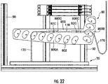
- FIG. 22 is a front view showing the few-core cable management section of the distribution rack illustrated in FIG. 2 .
- the few-core cable management section 80 comprises a base plate 800 attached to the rear frame 92, and a cable manager 802 attached to the base plate 800.
- the base plate 800 has a laterally-extending part 800A, and an obliquely-extending part 800B extending obliquely upwardly from an inner end of lateral laterally-extending part 800A.
- the base plate 800 is formed with a pair of laterally elongate holes 800C.
- a pair of support members 92C each standingly extending frontwardly from the rear frame 92 are inserted, respectively, into the laterally elongate holes 800C, so as to allow the base plate 800 to be supported to the rear frame 92 such that it is movable in the lateral direction.
- a plurality of the cable managers 802 are standingly provided on the laterally-extending part 800A such that they are arranged side-by-side in the lateral direction.
- the cable managers 802 standingly provided on the laterally-extending part 800A are arranged such that they are gradually located at a lower position toward the inward side.
- a plurality of the cable managers 802 are standingly provided on the obliquely-extending part 800B such that they are arranged side-by-side in the up-down direction.
- the cable managers 802 standingly provided on the obliquely-extending part 800B are arranged such that they are gradually located at a more inward position toward the upward side.
- the configuration of the cable manager 802 is substantially the same as that of the cable manager 210 in the jumper management section 20, wherein a plurality of partition plates are attached onto a center member at even intervals.
- the few-core cable management section 80 is configured to guide a single-core fiber 170 extending from the left few-core cable fixing section 70.
- FIG. 22 shows a case where the single-core fiber 170 is introduced into the left termination section 30.
- the single-core fiber 170 extending from the left few-core cable fixing section 70 is guided to one of the cable managers 802 of the laterally-extending part 800A to extend toward a laterally central region, and hung on one of the cable managers 802 of the obliquely-extending part 800B to form a sagging once.
- the single-core fiber 170 is introduced into the jumper management section 20.
- the single-core fiber 170 introduced into the jumper management section 20 is guided by one of the cable managers 210 of the jumper management section 20 toward one of the cassettes 320 of the left termination section 30, and connected to one of the adapters from the front side of the adapter. Based on the above sagging, the single-core fiber 170 receives a force pulling toward the jumper management section 20, so that it is possible to prevent the single-core fiber 170 from sagging between the clip member and the cable manager of the laterally-extending part 800A.
- the left few-core cable management section 80 can lead a single-core fiber 170 to the right region of the distribution rack.
- the single-core fiber 170 extending from the left few-core cable fixing section 70 is guided toward the obliquely-extending part 800B by one of the cable managers 802 of the laterally-extending part 800A, and further led toward the right region of the distribution rack by one of the cable managers 802 of the obliquely-extending part 800B.
- the single-core fiber 170 can be guided upwardly by the right few-core cable fixing section, and led to one of the cassettes of the right termination section 40.
- a few-core cable 160 can be fixed to the left few-core cable fixing section 70 by attaching the attaching portion 750 to the support bar 730 in the state in which the few-core cable 160 is retained by the cable retaining portion 760.
- the clip member 740 can be preliminarily attached to the few-core cable 160, and then attached to the support bar 730, so that an operation of fixing the few-core cable 160 needs not be conducted in a limited space and can be conducted without taking time and effort.
- the clip member 740 with the few-core cable 160 attached thereto can be attached to the support bar 730, so that it is possible to densely fix the few-core cables 160.
- the clip member 740 may be detached from the few-core cable 160, so that it is possible to facilitate the detaching operation.
- the left few-core cable fixing section 70 comprises the front rail 722 and the rear rail 724 each extending in the right-left direction, wherein the support bar 730 is movable along the front rail 722 and the rear rail 724 in the right-left direction.
- the few-core cables 160 can be densely arranged by moving the support bar 730 with the few-core cable 160 attached thereto by the clip member 740.
- the attaching portion 750 has a clip-like configuration, so that the clip member 740 can be attached to the support bar 730 by clipping the attaching portion 750 to the support bar 730.
- the cable retaining portion 760 comprises the cover part 766 which is swingable about a pivot axis extending longitudinally and formed along one of laterally-opposed edges thereof, wherein the other edge of the cover is configured to be fixable, whereby the few-core cable 160 can be retained by the cable retaining portion 760 in a state in which the few-core cable 160 is covered with the cover part 766, and the other end of the cover is fixed.
- the few-core cable 160 can be attached to the clip member 740 by a simple operation of swinging the cover part 766.
- the cable retaining portion 1760 is configured to retain the binding band member 1770 wound around the clip member 1740.
- the few-core cable 160 can be easily attached to the clip member 1740 by winding the binding band member 1770 around the few-core cable 160, and allowing the binding band member 1770 to be retained by the clip retaining portion 1760.
- the left few-core cable fixing section 70 is provided just below the left cable fixing section 50.
- the few-core cable 160 extending from a lower side can be introduced into the left termination section 30 in a state in which it is held by the left few-core cable fixing section 70.
- the distribution rack comprises the few-core cable management section 80 provided just above the left few-core cable fixing section 70 and configured to retain the few-core cable 160. According to this feature, an upper part of the few-core cable 160 is held by the few-core cable management section 80, so that it is possible to facilitate an operation of attaching the few-core cable 160 to the left few-core cable fixing section 70.
Landscapes
- Physics & Mathematics (AREA)
- General Physics & Mathematics (AREA)
- Optics & Photonics (AREA)
- Light Guides In General And Applications Therefor (AREA)
Abstract
Description
- The present invention relates to a distribution rack.
- In a data center in which a plurality of servers are arranged, a distribution rack is used to distribute a plurality of optical fiber cables extending from the outside such as a telecom company, to the servers. The distribution rack is internally provided with a fiber connection section for connecting a telecom company-side optical fiber cable to a server-side optical fiber cable.
- As a configuration of such a fiber connection section, a cassette-type fiber connection section is widely used which is capable being housed in a rack, as described in, e.g., the below-mentioned
Patent Documents 1 and 2. Specifically, after providing a cassette movable back and forth in a front-rear direction with respect to a rack, a telecom company-side optical fiber cable and a server-side optical fiber cable are introduced into the cassette from one side and the other side thereof, respectively, and then connected together in an internal space of the cassette via an adapter. - Patent Document 1:
JP4795884B - Patent Document 2:
JP3883113B - Here, an allowable bending radius is specified for an optical fiber, because if excessive bending is imposed on the optical fiber, failures in data transmission will occur. However, when optical fibers are connected using the above cassette movable back and forth in the front-rear direction, the optical fibers are likely to be bent at a bending radius less than the allowable bending radius, in an introduction zone where each of the optical fibers is introduced into the cassette, during pulling-out or pushing-in of the cassette.
- The present invention has been made in view of the above problem, and we have appreciated that it would be desirable to, even in a case where optical fibers are connected together in a back-and-forth movable cassette, prevent the optical fibers from undergoing excessive bending.
- The present invention provides a distribution rack which comprises a connection section connecting an end of a first optical fiber and an end of a second optical fiber together, wherein the connection section has a plurality of cassettes each internally formed with a housing space capable of housing an end portion of the first optical fiber and movable in a given range in a front-rear direction, wherein each of the cassettes has a pair of laterally opposed sidewalls, one sidewall of which is formed with a first introduction port capable of introducing the first optical fiber into the housing space therethrough, each of the cassettes comprising an adapter configured to allow the end of the first optical fiber introduced through the first introduction port to be connected thereto, and allow the end of the second optical fiber to be connected thereto; and wherein a guide portion is formed at the first introduction port, the guide portion having a pair of front and rear guide walls forming therebetween a guide space expanding in the front-rear direction toward a lateral direction, wherein each of the front and rear guide walls is formed in a curved shape which is convex toward the guide space in plan view.
- In the distribution rack of the present invention having the above feature, the first introduction port for introducing the first optical fiber therethrough is provided with the guide portion having the front and rear guide walls each formed in a curved shape which is convex toward the guide space, so that it is possible to prevent the first optical fiber from undergoing excessive bending, even when the cassette is moved in the front-rear direction.
- Preferably, in the distribution rack of the present invention, the guide portion has an arm extending above the guide space.
- According to this feature, even when the cassette is moved in the front-rear direction, the arm part can prevent the first optical fiber from being curved upwardly, thereby preventing the first optical fiber from undergoing excessive curvedness or up-down directional flexure.
- Preferably, the distribution rack of the present invention comprises a lateral guide member provided beside the one sidewalls of the plurality of cassettes, and formed in a frontwardly curved shape in plan view, wherein the first optical fiber is introduced into the first introduction port while being guided along a side surface of the lateral guide member.
- According to this feature, it is possible to prevent a portion of the first optical fiber outside the cassette from undergoing excessing curvedness.
- More preferably, the lateral guide member is disposed such that a frontwardmost area of the lateral guide member is located rearward of the first introduction port of the cassette when the cassette is moved to a frontwardmost position, and is located frontward of the first introduction port when the cassette is moved to a rearwardmost position.
- According to this feature, it is possible to suppress the movement of the portion of the first optical fiber outside the cassette due to the movement of the cassette.
- More preferably, the above distribution rack further comprises a first optical fiber fixing member provided beside and rearward of the lateral guide member and capable of fixing a part of the first optical fiber.
- According to this feature, it is possible to reliably guide the first optical fiber along the lateral guide member.
- Preferably, in the distribution rack of the present invention, the cassette is formed with a second housing space located frontward of the adapter and capable of housing an end portion of the second optical fiber, and the other sidewall of the cassette is formed with a second introduction port located frontward of the adapter and capable of introducing the end portion of the second optical fiber into the second housing space therethrough.
- According to this feature, the second optical fiber is housed in a front region of the cassette, so that the first optical fiber can be isolated from the second housing space, thereby preventing interference between the first optical fiber and the second optical fiber.
- Preferably, in the distribution rack of the present invention, the cassette is bilaterally symmetrical, wherein the cassette has a second introduction port formed at a position symmetrically opposed to the first introduction port, the second introduction port being provided with a second supporting member configured to guide the second optical fiber.
- According to this feature, one cassette can be used to handle both cases where the first optical fiber is introduced from the right side and from the left side. Further, the introduction of the first optical fiber and the installation of the second optical fiber-supporting member can be performed using the first and second optical fiber introduction ports formed bilaterally symmetrically.
- More preferably, the second supporting member has a restraint portion configured to restrain the second optical fiber in a vertical direction.
- According to this feature, the restraint portion can restrain the second optical fiber in the vertical direction, so that it is possible to prevent the second optical fiber from bending in the vertical direction, even when the cassette is moved in the front-rear direction.
- More preferably, in the above distribution rack, the cassette has a swingable portion located on a front side thereof to define the second housing space and configured to be swingable about a swing axis extending in the lateral direction, the swingable portion having a restraint portion configured to restrain the second optical fiber in a vertical direction.
- According to this feature, the swingable portion can be swung to facilitate housing the second optical fiber in the second housing space, and to prevent the second optical fiber from getting out of the second housing space, even when the cassette is moved in the front-rear direction.
- Preferably, the distribution rack of the present invention comprises a second fixing portion provided beside the second sidewalls of the plurality cassettes and capable of fixing a part of the second optical fiber.
- According to this feature, it is possible to, even when the cassette is moved, prevent the second optical fiber from moving along with the movement of the cassette.
- The present invention makes it possible to, even in a case where optical fibers are connected together in a back-and-forth movable cassette, prevent the optical fibers from undergoing excessive bending.
-
-
FIG. 1 is a diagram showing one example of a cabling system in a data center including a distribution rack according to one embodiment of the present invention. -
FIG. 2 is a front view showing the distribution rack according to this embodiment. -
FIG. 3 is a perspective view showing the distribution rack according to this embodiment. -
FIG. 4 is a perspective view showing a left cable fixing section illustrated inFIG. 2 , in the distribution rack according to this embodiment, wherein it shows a state in which cables are installed in the left cable fixing section. -
FIG. 5 is a perspective view showing the left cable fixing section illustrated inFIG. 2 , in the distribution rack according to this embodiment, wherein it shows a state in which cables are omitted. -
FIG. 6 is a perspective view showing a guide member of each cable fixing section in the distribution rack according to this embodiment. -
FIG. 7 is a side view showing the guide member of the cable fixing section in the distribution rack according to this embodiment. -
FIG. 8 is a perspective view showing a state in which an optical fiber cable is fixed to the guide member illustrated inFIG. 6 . -
FIG. 9 is an enlarged perspective view showing the configuration of a left termination section in the distribution rack illustrated inFIG. 2 . -
FIG. 10 is a perspective view showing a cassette constituting the left termination section illustrated inFIG. 9 . -
FIG. 11 is a top plan view showing the cassette of the left termination section illustrated inFIG. 9 and the vicinity thereof, wherein it shows a state in which the cassette is retracted. -
FIG. 12 is a top plan view showing the cassette of the left termination section illustrated inFIG. 9 and the vicinity thereof, wherein it shows a state in which the cassette is pulled out. -
FIG. 13 is a perspective view enlargedly showing a core wire guide member of the cassette illustrated inFIG. 10 and the vicinity thereof. -
FIG. 14 is a top plan view enlargedly showing the core wire guide member of the cassette illustrated inFIG. 10 and the vicinity thereof. -
FIG. 15 is a front view enlargedly showing a jumper management section of the distribution rack illustrated inFIG. 2 . -
FIG. 16 is a perspective view showing a cable manager constituting the jumper management section illustrated inFIG. 15 . -
FIG. 17 is a perspective view showing a base frame of a left few-core cable fixing section of the distribution rack illustrated inFIG. 2 . -
FIG. 18 is a perspective view enlargedly showing the left few-core cable fixing section of the distribution rack illustrated inFIG. 2 , in a state in which a few-core cable is fixed thereto. -
FIG. 19 is a perspective view showing a clip member to be used in the left few-core cable fixing section, in a state in which a cover thereof is opened. -
FIG. 20 is a perspective view showing the clip member to be used in the left few-core cable fixing section, in a state in which the cover is closed to fix an optical fiber cable thereto. -
FIG. 21 is a perspective view showing a clip member having another configuration. -
FIG. 22 is a front view showing a few-core cable management section of the distribution rack illustrated inFIG. 2 . - With reference to the drawings, a distribution rack according to one embodiment of the present invention will now be described in detail. It should be noted that optical fiber cables are partly omitted in the drawings for the purpose of illustration.
-
FIG. 1 is a diagram showing one example of a cabling system in a data center including a distribution rack according to one embodiment of the present invention. This cabling system 1 is a system for connecting a plurality of optical fiber-containing cables extending from a telecom company to servers disposed on various floors. As shown inFIG. 1 , a bundle of cables C1 from a telecom company extends around adata center 2, and optical fibers contained in the cables C1 are distributed to servers S11 to S34 installed on floors via first to fourth distribution racks 10A, 10B, 10C, 10D. Specifically, as shown inFIG. 1 , thefirst distribution rack 10A connects a part of a bundle of optical fiber-containing cables C1 extending from a telecom company, to two bundles of optical fiber-containing cables C2, C3 each extending from a respective one of thesecond distribution rack 10B and thethird distribution rack 10C. Thesecond distribution rack 10B couples the bundle of optical fiber-containing cables C2 extending from thefirst distribution rack 10A, to optical fiber-containing cables C5 extending from the servers S11 to S14. Thethird distribution rack 10C couples the bundle of optical fiber-containing cables C3 extending from thefirst distribution rack 10A, to optical fiber-containing cables C6 extending from the servers S21 to S24 and the bundle of optical fiber-containing cables C4 extending from thefourth distribution rack 10D. Thefourth distribution rack 10D couples the bundle of optical fiber-containing cables C4 extending from thethird distribution rack 10C, to optical fiber-containing cables C7 extending from the servers S31 to S34. It should be noted that, in the following description, the term "optical fiber cable" includes a multi-core cable containing a plurality of core wires, and a few-core cable containing a single core wire. - Based on the above configuration, among optical fibers of the cable C1 extending from the telecom company to the
first distribution rack 10A, a part of the optical fibers are communicably connected to the servers S11 to S14 via thesecond distribution rack 10B, and a part of the remaining optical fibers are communicably connected to the servers S21 to S24 via thethird distribution rack 10C. Further, the ultimately remaining optical fibers are communicably connected to the servers S31 to S34 via thethird distribution rack 10C and thefourth distribution rack 10D. Cables led in each distribution rack and cables led out from each distribution rack are arranged, e.g., under system floors or behind system ceilings. -
FIGS. 2 and3 show the distribution rack according to this embodiment, whereinFIG. 2 is a front view, andFIG. 3 is a perspective view. As shown inFIGS. 2 and3 , adistribution rack 10 has aframe 90, and comprises, inside the frame 90: ajumper management section 20 provided in a laterally central region thereof; aleft termination section 30 and aright termination section 40 provided on both lateral sides of thejumper management section 20; a leftcable fixing section 50 and a rightcable fixing section 60 each disposed laterally outward of a respective one of thetermination sections cable fixing section 70 provided on the left side of the bottom of the frame; and a few-corecable management section 80 provided just above the left few-core cable fixing section (cable fixing section) 70. - The
distribution rack 10 is designed to connect an optical fiber of an optical fiber cable inserted from a left top or bottom portion of theframe 90, to an optical fiber of an optical fiber cable inserted from a right top or bottom portion of theframe 90. It may also be configured to connect an optical fiber of an optical fiber cable inserted from a left upper portion of theframe 90 and an optical fiber of an optical fiber cable inserted from a left or right bottom portion of theframe 90, to an optical fiber of an optical fiber cable inserted from a right or left top or bottom portion of theframe 90. - The following description will be made about a case where core wires of a plurality of multi-core cables led in the
distribution rack 10 from a left upper side ofFIG. 2 and a few-core cable led in thedistribution rack 10 from a left lower side ofFIG. 2 are coupled to core wires of a plurality of multi-core cables led in thedistribution rack 10 from a right lower side ofFIG. 2 , within thedistribution rack 10. - The left
cable fixing section 50 is a region configured to fix abundle 110 ofoptical fiber cables 100 inserted from a left region of a top portion of theframe 90, and lead the optical fiber cables toward theleft termination section 30 at different height positions. In the leftcable fixing section 50, a sheath of each of the optical fiber cables is removed, and only a ribbon fiber extends toward theleft termination section 30. - The
left termination section 30 is a region configured to connect a fiber core wire extending from the leftcable fixing section 50, to one end of ajumper cable 150 or a single-core cable extending from the left few-corecable fixing section 70. The one end of thejumper cable 150 is connected to the optical fiber core wire of theoptical fiber cable 100 via an adapter. - In the
jumper management section 20, thejumper cable 150 is bridged between right and left sides thereof in a sagging state. - The right
cable fixing section 60 is a region configured to fix abundle 110 ofoptical fiber cables 100 inserted from a left region of a bottom portion of theframe 90, and lead the optical fiber cables toward theright termination section 40 at different height positions. In the rightcable fixing section 60, a sheath of each of the optical fiber cables is removed, and only a ribbon fiber extends toward theright termination section 40. - The
right termination section 40 is a region configured to connect a fiber core wire extending from the rightcable fixing section 60, to the other end of thejumper cable 150. The other end of thejumper cable 150 is connected to the optical fiber core wire via an adapter. - The left few-core
cable fixing section 70 is configured to fix an optical fiber cable inserted from the left region of the bottom portion of theframe 90, and lead the optical fiber cable as a single-core cable toward theleft termination section 30 via the jumper management section. It should be noted here that the location of the left few-corecable fixing section 70 is not limited to the bottom portion of thedistribution rack 10, but may be any lower portion of thedistribution rack 10. - The few-core
cable management section 80 is configured to support the optical fiber extending from the left few-corecable fixing section 70. - The
frame 90 comprises a rectangular-shapedfront frame 91, arear frame 92 having the same shape as that of thefront frame 91, and a plurality of cross members 93 (FIG. 5 ) are bridged between thefront frame 91 and therear frame 92. Thefront frame 91 and therear frame 92 are held in parallel with a given distance therebetween by thecross members 93. - The cable fixing section in the distribution rack illustrated in
FIG. 2 will be described below. Although the following description will be made about the left cable fixing section, the right cable fixing section also has a bilaterally symmetrical similar configuration. -
FIGS. 4 and5 are perspective views showing the left cable fixing section illustrated inFIG. 2 , in the distribution rack according to this embodiment, whereinFIG. 4 shows a state in which cables are installed in the left cable fixing section, andFIG. 5 shows a state in which cables are omitted. As shown inFIGS. 4 and5 , a plurality ofbundle 110 ofoptical fiber cables 100 is inserted into the leftcable fixing section 50. In the leftcable fixing section 50, a plurality ofguide members 502A to 502H are arranged side-by-side in an up-down (vertical) direction. Each of theguide members 502A to 502H is bridged between and fixed to a pair of vertically-extendingpillar members rear frame 92 of theframe 90 constituting thedistribution rack 10. -
FIGS. 6 and 7 show the guide member of the cable fixing section in the distribution rack according to this embodiment, whereinFIG. 6 is a perspective view, andFIG. 7 is a side view. As shown inFIGS. 6 and 7 , theguide member 502 comprises: abase part 504 extending in a front-rear direction; an attachingpart 508 expending laterally from a rear end of thebase part 504; and a plurality ofarm parts base part 504. - The
base part 504 is a plate-shaped part whose surface becomes a vertical surface in an attached state and which extends in the front-rear direction. Thebase part 504 has an intermediate area 504C extending in a constant up-down directional width, afront end area 504B extending obliquely upwardly with respect to the intermediate area 504C, and arear end area 504A having an up-down directional width expanding upwardly. - The attaching
part 508 is a plate-shaped part whose surface becomes vertical in the attached state and which extends laterally inwardly from an upper area of therear end area 504A. - Each of the
arm parts base part 504. Front-rear directional intervals between adjacent ones of thearm parts guide members 502 of the leftcable fixing section 50, the front-rear directional intervals between adjacent ones of the arm parts 510 are set to be equal to each other. It is to be understood that the interval may be arbitrarily set depending on the diameter of a cable to be routed or the number of the cables. - The
frontwardmost arm part 504A is connected to a front end of thefront end area 504B. Each of upper and lower edges of thefrontwardmost arm part 504A is formed in a wave shape with a continuous undulation. - The second-
frontwardmost arm part 510B is connected to a boundary between the intermediate area 504C and thefront end area 504B. Each of upper and lower edges of the second-frontwardmost arm part 504B is formed in a wave shape with a continuous undulation. - The
rearwardmost arm part 510Z extends laterally outwardly from a lower area of therear end area 504A of thebase part 504. - Based on the above configuration, receiving
spaces arm parts spaces - As shown in
FIG. 5 , the first toeighth guide members 502 are attached to the leftcable fixing section 50 at approximately even intervals in the downward direction from the top. Each of theguide members 502 is fixed by screwing distal ends of therearwardmost arm part 510Z and the attachingpart 508 to the pair ofpillar members cable fixing section 50 in which the optical fiber cables extend from the top thereof, the number of the arm parts 510 in a lower one of theguide members 502 is set to be equal to or less than that in an upper one of theguide members 502. - As shown in
FIG. 5 , each of thefirst guide member 502A and thesecond guide member 502B has eight arm parts 510, and thethird guide member 502C, thefourth guide member 502D and thefifth guide member 502E have, respectively, seven arm parts 510, six arm parts 510 and five arm parts 510. Further, thesixth guide member 502F, theseventh guide member 502G and theeighth guide member 502H have, respectively, four arm parts 510, three arm parts 510 and two arm parts 510. - As shown in
FIG. 4 , in the leftcable fixing section 50, optical fiber cables extend downwardly from the top of the leftcable fixing section 50, while being aligned to form a plurality of rows in the right-left (lateral) direction and a plurality of columns in the front-rear direction. Theoptical fiber cables 100 are received in each of the receiving spaces 512 in a state in which they are aligned to form one or two columns in the front-rear direction and three to five rows in the right-left direction. Each of theoptical fiber cables 100 is received in up-down directionally corresponding ones of the receiving spaces 512 of theguide members 502. - The rearwardmost column of
optical fiber cables 100 are received in and guided by therearwardmost receiving spaces 512Z of the first toeighth guide members 502A to 502H, and fixed to theeighth guide member 502H, wherein a sheath of each of them is peeled off at a position below theeighth guide member 502H. - The second-and third-rearwardmost columns of
optical fiber cables 100 are received in and guided by the second-rearwardmost receiving spaces 512 of the first toseventh guide members 502A to 502G, and fixed to theseventh guide member 502G, wherein a sheath of each of them is peeled off at a position below theseventh guide member 502G. - The fourth-and fifth-rearwardmost columns of
optical fiber cables 100 are received in and guided by the third-rearwardmost receiving spaces 512 of the first to sixthguide members 502Ato 502F, and fixed to thesixth guide member 502F, wherein a sheath of each of them is peeled off at a position below thesixth guide member 502F. - The sixth-and seventh-rearwardmost columns of
optical fiber cables 100 are received in and guided by the fourth-rearwardmost receiving spaces 512 of the first tofifth guide members 502A to 502E, and fixed to thefifth guide member 502E, wherein a sheath of each of them is peeled off at a position below thefifth guide member 502E. - The eighth-and ninth-rearwardmost columns of
optical fiber cables 100 are received in and guided by the fifth-rearwardmost receiving spaces 512 of the first tofourth guide members 502A to 502D, and fixed to thefourth guide member 502D, wherein a sheath of each of them is peeled off at a position below thefourth guide member 502D. - The tenth-and eleventh-rearwardmost columns of
optical fiber cables 100 are received in and guided by the sixth-rearwardmost receiving spaces 512 of the first tothird guide members 502A to 502C, and fixed to thethird guide member 502C, wherein a sheath of each of them is peeled off at a position below thethird guide member 502C. - The twelfth-and thirteenth-rearwardmost columns of
optical fiber cables 100 are received in and guided by the seventh-rearwardmost receiving spaces 512 of the first andsecond guide members second guide member 502B, wherein a sheath of each of them is peeled off at a position below thesecond guide member 502B. -
FIG. 8 is a perspective view showing a state in which an optical fiber cable is fixed to the guide member illustrated inFIG. 6 . InFIG. 8 , for the purpose of illustration, only one of a front column ofoptical fiber cables 100A and one of a rear column ofoptical fiber cables 100B, in thefrontwardmost receiving space 512A, are shown, and the remainingoptical fiber cables 100 are omitted. - The
optical fiber cable 100 comprises: an opticalfiber core wire 120 obtained by covering a bare fiber made of glass and composed of a core and a clad, with UV coating or the like; and a sheath (outer covering) surrounding one or more optical fiber core wires. In this embodiment, the optical fiber core wire is used to form a cable, in the form of a tape core wire (ribbon fiber) obtained by forming a plurality of optical fiber core wires aligned side-by-side, into a tape-like shape. - Each of the front column of
optical fiber cables 100A amongoptical fiber cables 100 received in thefrontwardmost receiving space 512A is fixed to thefrontwardmost arm part 510A by abinding band 520. Each of the upper and lower edges of thefrontwardmost arm part 510A is formed with an undulation, as mentioned above. Thus, during the fixing operation, it is possible to restrain theoptical fiber cable 100A from moving laterally. Asheath 115 of each of the front column ofoptical fiber cables 100A is removed at a position below thefrontwardmost arm part 510A, so as to expose theribbon fiber 120. - Each of the rear column of
optical fiber cables 100B among theoptical fiber cables 100 received in thefrontwardmost receiving space 512A is fixed to the second-frontwardmost arm part 510B by abinding band 520. Each of the upper and lower edges of the second-frontwardmost arm part 510B is formed with an undulation, and thus, during the fixing, it is possible to restrain theoptical fiber cable 100B from moving laterally. Asheath 115 of each of the front column ofoptical fiber cables 100B is removed at a position below the second-frontwardmost arm part 510B, so as to expose theribbon fiber 120. AlthoughFIG. 8 shows a single-core optical fiber cable, a multi-core optical fiber cable can be fixed in a similar manner. - The
ribbon fiber 120 of theoptical fiber cable 100 whose sheath had been peeled off in the above manner is led to thecassettes 320 of theleft termination section 30 located at approximately the same height position as that of theribbon fiber 120. - Except that the right
cable fixing section 60 is bilaterally symmetrical to the leftcable fixing section 50, they are identical in terms of configuration. - In this embodiment, the first to
eighth guide members 502 of the leftcable fixing section 50 has thearm parts spaces optical fiber cables 100 by installing theoptical fiber cables 100 in the plurality of receivingspaces optical fiber cables 100 to one of the arm parts. - In this embodiment, when
optical fiber cables 100 is arranged in a single column in the front-rear direction, theoptical fiber cables 100 can be fixed to thefrontwardmost arm part 510A, and, whenoptical fiber cables 100 are arranged in a plurality of columns in the front-rear direction, theoptical fiber cables 100 can be fixed to thefrontwardmost arm part 510A and the second-frontwardmost arm part 510B, in two groups, and thus, even in a case whereoptical fiber cables 100 are arranged in high density, it is possible to easily fix theoptical fiber cables 100. - In this embodiment, the
frontwardmost arm part 510A is provided above the second-frontwardmost arm part 510B. Thus, in a case where a plurality of columns ofoptical fiber cables 100 arranged in the same receiving space are fixed, the columns ofoptical fiber cables 100 can be fixed, respectively, to the arm parts at different height positions. Further, when the cables are fixed to the second-frontwardmost arm part 510B, it is possible to prevent the second-frontwardmost arm part 510B from hiding behind thefrontwardmost arm part 510A, thereby improving working efficiency of the fixing operation. - In this embodiment, each of the upper and lower edges of the
frontwardmost arm part 510A and the upper and lower edges of the second-frontwardmost arm part 510B is formed with an undulation. This makes it possible to prevent anoptical fiber cable 100 from moving laterally even when fixing theoptical fiber cable 100 using thebinding band 520 or the like. It should be noted here that such an undulation may be provided in only one of the upper and lower edges, or may be provided in one of thefrontwardmost arm part 510A and the second-frontwardmost arm part 510B. - In this embodiment, the first to
eighth guide members 502 are configured such that a lower one thereof is gradually reduced in terms of the number of arm parts. This makes it possible to fix a front-side column ofoptical fiber cables 100 to the arm part on a relatively upper side of the cable fixing section, and fix a rear-side column ofoptical fiber cables 100 to the arm part on a relatively lower side of the cable fixing section, thereby facilitating the fixing operation foroptical fiber cables 100. - The configuration of the
left termination section 30 will be described below.FIG. 9 is an enlarged perspective view showing the configuration of the left termination section in the distribution rack illustrated inFIG. 2 .FIG. 10 is a perspective view showing the cassette constituting the left termination section illustrated inFIG. 9 .FIGS. 11 and12 show the cassette of the left termination section illustrated inFIG. 9 and the vicinity thereof, whereinFIG. 11 shows a state in which the cassette is retracted, andFIG. 12 shows a state in which the cassette is pulled out such that a jumper cable-side connector can be attached/detached. - As shown in
FIG. 9 , the left termination section comprises: arail frame 310 fixed to theframe 90 with a given lateral distance therebetween; a plurality ofcassettes 320 supported by therail frame 310; alateral guide member 330 provided at a position front of therail frame 310 on the side of the leftcable fixing section 50; a core wire fixing portion (optical fiber cable fixing member) 340 disposed on the lateral side of thelateral guide member 330; and a jumpercable fixing portion 350 disposed front of a right portion of therail frame 310 on the side of thejumper management section 20. - The
rail frame 310 is composed of a plurality of pairs of left andright rails right rails rails - Each of the
cassettes 320 is made of metal such as stainless steel, resin or the like, and comprised acassette body 360, and aswingable portion 370 swingably attached to a front end of thecassette body 360. Thecassette 320 is configured such that the after-mentionedsliders rails cassette 320 can selectively take a detached position where it is detached from therail frame 310, a pullout position where it is pulled out while being supported by therails rails cassette 320, it is desirable to conduct such an operation in a state in which thecassette 320 is taken out from therail frame 310. - The
cassette body 360 comprises: abottom plate part 361; a pair ofsidewall parts bottom plate part 361; and arear wall part 363 provided to stand from a rear edge of thebottom plate part 361. - The
bottom plate part 361 is a region formed in an approximately rectangular plate shape. - The pair of
sidewall parts bottom plate part 361. A front-rear directional length of each of thesidewall parts bottom plate part 361, and a part of each of thesidewall parts bottom plate part 361. A pair ofslide parts sidewall parts slide parts sidewall parts sidewall parts adapters 322. Here, as described in detail later, theopening 364A on the side of the leftcable fixing section 50 functions as an opening for introducing a core wire of anoptical fiber cable 100 therethrough, wherein a corewire guide member 380 is attached thereto. Further, the opening 364B on the side of thejumper management section 20 functions as a region for attaching a jumper cable supporting member 326 thereto. - The pair of the
sidewall parts cutouts sidewall parts - The
rear wall part 363 is provided to extend between the pair of thesidewall parts - An
adapter retaining portion 322A is provided along a front edge of thebottom plate part 361 swingably in the front-rear direction, and a plurality ofadapters 322 are attached to theadapter retaining portion 322A such that they are arranged side-by-side in the lateral direction over the entire width of thebottom plate part 361. The plurality ofadapters 322, the pair ofsidewall parts rear wall part 363 surroundingly define a corewire housing space 366 within thecassette 320. - A part of the
bottom plate part 361 facing the corewire housing space 366 is formed with a left front-side guide protrusion 361A, a leftintermediate guide protrusion 361B, a left rear-side guide protrusion 361C, a right front-side guide protrusion 361D, a rightintermediate guide protrusion 361E, and a right rear-side guide protrusion 361F. Each of theseguide protrusions bottom plate part 361. - Each of the left front-
side guide protrusion 361A and the right front-side guide protrusion 361D is located rearward of a respective one of theopenings 364A, 364B. Each of the left front-side guide protrusion 361A and the right front-side guide protrusion 361D has a rear part formed in a plate shape extending in the front-rear direction, and a front part extending frontwardly while curving toward a central region of the cassette. - Each of the left rear-
side guide protrusion 361C and the right rear-side guide protrusion 361F is located around a respective one of two rear corners of thebottom plate part 361. Each of the left rear-side guide protrusion 361C and the right rear-side guide protrusion 361F has a front part formed in a plate shape extending in the front-rear direction, and a rear part extending rearwardly while curving toward the central region of the cassette. - The left
intermediate guide protrusion 361B is located between the rear part of the left front-side guide protrusion 361A and the front part of the left rear-side guide protrusion 361C, in a state in which they are aligned with each other in the front-rear direction. - The right
intermediate guide protrusion 361E is located between the rear part of the right front-side guide protrusion 361D and the front part of the right rear-side guide protrusion 361F, in a state in which they are aligned with each other in the front-rear direction. - The
swingable portion 370 comprises: abottom plate part 371; a pair ofsidewall parts 372 each provided to stand along a respective one of opposed lateral edges of thebottom plate part 371; a front face-formingpart 373 provided to stand along a front edge of thebottom plate part 371 perpendicularly to thebottom plate part 371; and a fold-back part 374 provided to extend rearwardly from an upper edge of the front face-formingpart 373. Theswingable portion 370 is configured such that rear ends of the pair ofsidewall parts 372 is pivotally connected, respectively, to thesidewall parts cassette 320 at positions frontward of theadapters 322. Theswingable portion 370 is configured to be swingable between a state in which thebottom plate part 371 is set horizontally and located on the same plane as that of thebottom plate part 361 of thecassette 320, and a state in which thebottom plate part 371 is tilted obliquely downwardly and frontwardly. - When the
swingable portion 370 is set in a horizontal posture, the pair ofsidewall parts 372, the front face-formingpart 373, the fold-back part 374 and theadapters 322 surroundingly define ajumper housing space 375. -
FIGS. 13 and 14 enlargedly show the core wire guide member of the cassette illustrated inFIG. 10 and the vicinity thereof, whereinFIG. 13 is a perspective view, andFIG. 14 is a top plan view. - As shown in
FIGS. 13 and 14 , the corewire guide member 380 has abase end part 382, and awidened part 384 extending from thebase end part 382 toward the lateral direction while gradually expanding in the front-rear direction. - The
base end part 382 is a region in which it extends in an approximately constant width and which is located inside the corewire housing space 366 in an attached state thereof. Thebase end part 382 is formed with aslit 382A extending from a top end of thebase end part 382 along a widthwise center line thereof. Thetop end 382 B of thebase end part 382 is formed to have a width larger than that of a part of thebase end part 382 on the side of thewidened part 384. A pair ofguide walls 382C are formed, respectively, along opposed edges of the part of thebase end part 382 on the side of thewidened part 384. - The
widened part 384 is formed such that a front-rear directional width thereof is expanded toward a laterally outward direction. A pair ofguide walls 384A are formed, respectively, along front-rear directionally opposed edges of a widening part of thewidened part 384. The pair ofguide walls 384A extend in a laterally frontward direction and in a laterally rearward direction, respectively. Each of theguide walls 384A is formed in a curved shape which is convex toward a front-rear directionally central region of thewidened part 384. Further, thewidened part 384 is provided with a pair ofarms 384B each extending thereabove in a covering manner. - The
bottom plate part 361 has a pair of holdingprotrusions 361G formed in the vicinity of theopening 364A such that they are opposed to each other in the front-rear direction. The holdingprotrusions 361G stand from thebottom plate part 361 and then bend such that they extend toward each other. When thebase end part 382 is inserted into theopening 364A from the outside, and then fitted between the pair of holdingprotrusions 361G, thebase end part 382 is placed in a state in which thetop end 382B thereof is located inside the holdingprotrusions 361G, and an upper surface thereof is covered by the pair of holdingprotrusions 361G, whereby the corewire guide member 380 can be fixed to thecassette body 360. - Further, a part of the
bottom plate part 361 corresponding to the front-rear directionally intermediate region of the corewire housing space 366 is formed with the after-mentionedsleeve retaining part 3611, and a branchingportion retaining part 361H for retaining the after-mentioned branchingportion 130. The branchingportion retaining part 361H is provided on both lateral sides of thesleeve retaining part 3611. - The jumper
cable supporting member 390 has amember body 392 located on a laterally outward side of thecutout 365B, and an attachingpart 394 extending from themember body 392 along thesidewall part 362B. - The attaching
part 394 extends in the front-rear direction along an outer surface of thesidewall part 362B, and a distal end thereof is bent toward thecassette 320. The distal end of the attachingpart 394 is formed in a similar shape to that of thebase end part 382 of the core wire guide portion 324, and the jumpercable supporting member 390 is fixed to thecassette body 360 by inserting the attaching part into the opening 364B. - In an attached state, the
member body 392 is located beside thecutout 365B. Themember body 392 has: abase plate part 392A extending toward thejumper management section 20; astanding part 392B standing upwardly from an edge of thebase plate part 392A on the side of thejumper management section 20; and a fold-back part 392C extending from an upper edge of thestanding part 392B toward theswingable portion 370. - The
slide parts cassette body 360 are set, respectively, in the grooves of therails cassette 320 to be held movably in the front-rear direction. Thus, thecassette 320 can selectively take the retracted position where it is pushed rearwardly, the pullout position where it is pulled frontwardly, and the detached position where it is detached from therail frame 310. In the pullout position, it is possible to swing theswingable portion 370 with respect to thecassette body 360. When laying out aribbon fiber 120 of anoptical cable 100, this operation may be conducted in a state in which thecassette 320 is set in the detached position, and, when laying out ajumper cable 150, this operation may be conducted in a state in which thecassette 320 is set in the pullout position, and further theswingable portion 370 is swung downwardly. - In a state in which the
cassette 320 is set in the retracted position, thelateral guide member 330 is disposed laterally outward of and adjacent to the corewire guide member 380. Thelateral guide member 330 extends vertically with a constant horizontal sectional shape. - The
lateral guide member 330 includes: aflat surface part 332 extending along a top end of thewidened part 384 of the corewire guide member 380 in the state in which thecassette 320 is set in the retracted position; and acurved surface part 334 arcuately extending from a front end of theflat surface part 332 to the corewire fixing portion 340. - In the state in which the
cassette 320 is set in the retracted position, a front end of theflat surface part 332 is approximately aligned, in the front-rear direction, with a front end of thewidened part 384 of the corewire guide member 380. - The core
wire fixing portion 340 is provided rearward of and continuous with thecurved surface part 334 of thelateral guide member 330.
The corewire fixing portion 340 has a plurality ofslits 342 provided at given intervals and each opened laterally, frontwardly and rearwardly in a horizontal direction. - The jumper
cable fixing portion 350 is disposed rearward of the jumpercable supporting member 390. The jumpercable fixing portion 350 has a plurality ofslits 352 provided at given intervals and each opened laterally, frontwardly and rearwardly in a horizontal direction. Each of theslits 352 is opened on the front and rear side of the jumpercable fixing portion 350 and the lateral side of the jumpercable fixing portion 350 facing thejumper management section 20. - A
ribbon fiber 120 of anoptical fiber cable 100 whose sheath had been peeled off in the leftcable fixing section 50 is led to extend toward the corewire fixing portion 340, and clamped by one of theslits 342 of the corewire fixing portion 340, so that it is fixed to the corewire fixing portion 340. Here, it is desirable that one of theslits 342 of the corewire fixing portion 340 to which theribbon fiber 120 is fixed has a height position corresponding to that of one of thecassettes 320 into which theribbon fiber 120 is subsequently introduced. - The
ribbon fiber 120 fixed to the corewire fixing portion 340 is led along thelateral guide member 330, and further lead between the pair ofguide walls 384A of thewidened part 384 of the corewire guide member 380. Then, theribbon fiber 120 is introduced from theopening 364A of thecassette 320 into the corewire housing space 366. As shown inFIGS. 13 and 14 , after theribbon fiber 120 introduced into the corewire housing space 366 extends rightwardly, it is lead rearwardly along the right front-side guide protrusion 361D. Then, after extending rearwardly, theribbon fiber 120 is led laterally outwardly (leftwardly) by the right rear-side guide protrusion 361F. Then, after extending laterally outwardly, theribbon fiber 120 is led frontwardly by the left rear-side guide protrusion 361C. Then, after extending frontwardly, theribbon fiber 120 is led laterally inwardly (rightwardly) by the left front-side guide protrusion 361A. Then, after extending laterally inwardly, theribbon fiber 120 is led rearwardly by the right front-side guide protrusion 361D. Then, after extending rearwardly, theribbon fiber 120 is led toward a central region of the corewire housing space 366 by the right rear-side guide protrusion 361F, and connected to atape core wire 122 from a fan-out branchingportion 130 by afusion sleeve 132. - The fan-out branching
portion 130 is configured to divide thetape core wire 122 connected to theribbon fiber 120 by thefusion sleeve 132, into a plurality of single-core fibers 140. Each of the single-core fibers 140 is surrounded by a protective tube or a sheath, and aconnector 140A is attached to an end thereof. Each of the single-core fibers 140 extends frontwardly from the branchingportion 130, and theconnector 140A at the end of the single-core fiber 140 is connected to one of theadapters 322 from the rear side of theadapter 322. - Further, a
connector 152 of ajumper cable 150 is connected to one of theadapters 322 from the front side of theadapter 322. Ajumper cable 150 is led to extend from thejumper management section 20, and clamped by one of theslits 342 of the jumpercable fixing portion 350 located at a height position corresponding to that of one of thecassettes 320 to which thejumper cable 150 is introduced. Then, thejumper cable 150 is introduced from the jumpercable fixing portion 350 into the jumpercable supporting member 390 from the rear side of the jumpercable supporting member 390. Thejumper cable 150 is guided into thecutout 365B while being held by the standingpart 392B and the fold-back part 392C of the jumpercable supporting member 390. Then, thejumper cable 150 is guided from thecutout 365B into thejumper housing space 375, and the connector at the end thereof is connected to one of theadapter 322 from the front side of theadapter 322. - When laying out the
ribbon fiber 120 within thecassette 320, thecassette 320 is set in the detached position where it is moved frontwardly and detached, to conduct this operation. - In the state in which the
cassette 320 is detached from therail frame 310, theribbon fiber 120 is introduced from theopening 364A of thecassette 320 into the corewire housing space 366. Then, theribbon fiber 120 introduced into the corewire housing space 366 is led to go around the corewire housing space 366 as many times as needed, along the right front-side guide protrusion 361D, the right rear-side guide protrusion 361F, the left rear-side guide protrusion 361C and the left front-side guide protrusion 361A, and further bent toward the central region of the corewire housing space 366, along the right front-side guide protrusion 361D and the right rear-side guide protrusion 361F. Then, theribbon fiber 120 is connected to thetape core wire 122, and reinforced by thefusion sleeve 132. Here, the fan-out branchingportion 130 and the single-core fibers 140 and thetape core wire 122 connected to the branchingportion 130 may be preliminarily attached to thecassette 320, and theconnectors 140A of the single-core fibers 140 may be preliminarily connected to the adapters. - After the
ribbon fiber 120 is laid out within the corewire housing space 366 in the above manner, thecassette 320 is attached to therail frame 310, and set in the pullout position. Then, in this pullout position, theribbon fiber 120 is disposed to extend along thelateral guide member 330 such that no excessive bending is applied thereto, and inserted in one of theslits 342 of the corewire fixing portion 340. - Thus, even when the
cassette 320 is displaced in the front-rear direction, theribbon fiber 120 can be led to extend from the corewire fixing portion 340 along an outer surface of thelateral guide member 330, and further guided to theopening 364A along therear guide wall 384A of the corewire guide member 380. This makes it possible to prevent theribbon fiber 120 from undergoing excessive bending. - Further, when laying out the
jumper cable 150, this operation is conducted in a state in which thecassette 320 is moved frontwardly, and further theswingable portion 370 is swung such that it is tilted obliquely downwardly with respect to thecassette body 360. - First of all, the
jumper cable 150 extending from thejumper management section 20 is inserted in one of theslits 352 of the jumpercable fixing portion 350 corresponding to one of thecassettes 320 to which thejumper cable 150 is laid out. Then, thejumper cable 150 is guided frontwardly from the jumpercable fixing portion 350, and led to thecutout 365B while being placed on the jumpercable supporting member 390. In this process, thejumper cable 150 is surrounded by arestraint portion 392D composed of thebase plate part 392A, the standingpart 392B and the fold-back part 392C of the jumpercable supporting member 390, so that it is possible to hold thejumper cable 150 so as not to spread in a height direction and in the lateral direction. Then, theconnector 152 at the end of thejumper cable 150 is connected to one of theadapters 322 from the front side of theadapter 322. Then, after all of thejumper cables 150 to be housed in thiscassette 320 are laid out in the same manner, theswingable portion 370 is swung such that it becomes parallel to thecassette body 360. In this process, thejumper cable 150 is disposed such that it is surrounded by arestraint portion 376 composed of thebottom plate part 371, the front face-formingpart 373 and the fold-back part 374. This allows thejumper cable 150 to be housed in thejumper housing space 375 so as not to spread in the up-down direction. - Then, the
cassette 320 is pushed and returned to the retracted position. In this process, theribbon fiber 120 is guided such that it is bent along thefront guide wall 384A of the corewire guide member 380, so that it is possible to prevent theribbon fiber 120 from undergoing excessive bending. - The core
wire guide member 380 is provided in the above manner. This, when thecassette 320 is set in a cabling position where it is pulled out frontwardly, theribbon fiber 120 is guided by thelateral guide member 330 and therear guide wall 384A, and, when thecassette 320 is set in the retracted position where it is pushed rearwardly, theribbon fiber 120 is guided by thelateral guide member 330 and thefront guide wall 384A, so that it is possible to prevent excessive bending. In this embodiment, the corewire guide member 380 is formed as a separate component from thecassette 320. Alternatively, it may be formed integrally with thecassette 320. - In this embodiment, the core
wire guide member 380 having the front andrear guide walls 384A each formed in a curved shape which is convex toward a guide space defined therebetween is provided in theopening 364A for introduction of theribbon fiber 120, so that it is possible to prevent theribbon fiber 120 from undergoing excessive bending, even when thecassette 320 is moved in the front-rear direction. - In this embodiment, the core
wire guide member 380 has thearms 384B extending above the guide space, so that, even when thecassette 320 is moved in the front-rear direction, thearms 384B can prevent theribbon fiber 120 from bending upwardly, thereby preventing theribbon fiber 120 from undergoing excessive curvedness or up-down directional flexure. - In this embodiment, the
lateral guide member 330 is provided beside thesidewalls 362A of the plurality ofcassettes 320, and formed in a frontwardly curved shape in plan view, wherein theribbon fiber 120 is introduced into theopening 364A while being in contact with along a side surface of thelateral guide member 330. This makes it possible to prevent a portion of theribbon fiber 120 outside thecassette 320 from undergoing excessive curvedness - In this embodiment, the
lateral guide member 330 is disposed such that a frontwardmost area of a front surface of thelateral guide member 330 is located rearward of theopening 364A of thecassette 320 when thecassette 320 is moved to a frontwardmost position, and is located frontward of theopening 364A of thecassette 320 when thecassette 320 is moved to a rearwardmost position. This makes it possible to suppress the movement of the portion of theribbon fiber 120 outside thecassette 320 due to the movement of thecassette 320. - In this embodiment, the core
wire fixing member 340 capable of fixing a part of theribbon fiber 120 is further provided beside and rearward of thelateral guide member 330. This makes it possible to reliably guide theribbon fiber 120 along thelateral guide member 330. - In this embodiment, the
cassette 320 is formed with thejumper housing space 375 located frontward of theadapter 322 and capable of housing an end portion of thejumper cable 150, and theright sidewall 362B of thecassette 320 is formed with thecutout 365B located frontward of theadapter 322 and capable of introducing the end portion of thejumper cable 150 into thejumper housing space 375 therethrough. Thus, thejumper cable 150 can be housed in a front region of thecassette 320, so that it is possible to isolate theribbon fiber 120 from the jumper housing space, thereby preventing interference between theribbon fiber 120 and thejumper cable 150. - In this embodiment the
cassette 320 is bilaterally symmetrical, wherein thecassette 320 has the opening 364B formed in theright sidewall 362B at a position symmetrically opposed to theopening 364A, and wherein the opening 364B is provided with the jumpercable supporting member 390 configured to guide thejumper cable 150. Thus onecassette 320 can be used to handle both cases where theribbon fiber 120 is introduced from the right side and from the left side. Further, the introduction of theribbon fiber 120 and the installation of the jumper cable supporting member can be performed using theopenings 364A, 354B formed bilaterally symmetrically. - In this embodiment, the jumper
cable supporting member 390 has therestraint portion 392D configured to restrain thejumper cable 150 in the up-down direction. Thus, therestraint portion 392D can restrain thejumper cable 150 in the up-down direction, so that it is possible to prevent the jumper cable from bending in the up-down direction, even when thecassette 320 is moved in the front-rear direction. - In this embodiment, the
cassette 320 has theswingable portion 370 located on a front side thereof to define thejumper housing space 375 and configured to be swingable about a swing axis extending in the lateral direction, wherein theswingable portion 370 has therestraint portion 376 configured to restrain thejumper cable 150 in the up-down direction. Thus, theswingable portion 370 can be swung to facilitate housing thejumper cable 150 in thejumper housing space 375, and to prevent thejumper cable 150 from getting out of thejumper housing space 375, even when thecassette 320 is moved in the front-rear direction. - In this embodiment, the jumper
cable fixing portion 350 capable of fixing a part of thejumper cable 150 is provided beside thesecond sidewalls 362B of theplurality cassettes 320. This makes it possible to, even when thecassette 320 is moved, prevent thejumper cable 150 from moving along with the movement of thecassette 320. -
FIG. 15 is a front view enlargedly showing the jumper management section of the distribution rack illustrated inFIG. 2 .FIG. 16 is a perspective view showing a cable manager constituting the jumper management section illustrated inFIG. 15 . - As shown in
FIG. 15 , thejumper management section 20 is composed of two groups ofcable managers 210, which are arranged bilaterally symmetrically. As shown inFIG. 16 , each of thecable managers 210 comprised acenter member 212 extending like a rod, and a plurality ofpartition plates 214 provided on thecenter member 212 at given intervals. - The
center plate 212 has a base end fixed to a rear part of theframe 90, and extends frontwardly in a horizontal direction. Thecenter member 212 is formed in an approximately semicircular shape in cross-section, and disposed at a tilt such that one lateral end thereof on the side of a lateral center of thejumper management section 20 is located lower than the other lateral end. - The plurality of
partition plates 214 are provided in evenly spaced-apart relation from a front end of thecenter member 212. Each of thepartition plates 214 has an outer shape approximately similar to the cross-sectional shape of thecenter member 212, and annularly surrounds the entire circumference of thecenter member 212.Concave areas 216 are formed between adjacent ones of thepartition plates 214 and between a rearwardmost one of thepartition plates 214 and the frame. - The cable managers of the left group are arranged side-by-side such that they gradually spread leftwardly toward a downward direction, and the cable managers of the right group are arranged side-by-side such that they gradually spread rightwardly toward the downward direction. That is, the right and left groups of cable managers are arranged such that the overall width thereof gradually increases toward the downward direction.
- A
jumper cable 150 is bridged between laterally corresponding two of the right and left groups ofcable managers 210 in a sagging state, and a left end and a right end thereof are introduced, respectively, into theleft termination section 30 and theright termination section 40. -
Jumper cables 150 extending from two or more of the plurality ofcassettes 320 are hung on each of thejumper cables 210. For example, sixjumper cables 150 extending from the uppermost and second-to sixth-uppermost cassettes 320 are hung on theuppermost jumper manager 210 inFIG. 16 . Further, thejumper cables 150 each corresponding to a respective one of thecassette 320 are received, respectively, in different ones of theconcave areas 216, for example, such that ajumper cable 150 to be connected to the uppermost cassette 320Ais received in the frontmostconcave area 216, and ajumper cable 150 to be connected to the second-uppermost cassette 320B is received in the second-frontmostconcave area 216. In this way, a plurality ofjumper cables 150 are bridged between thecassettes 320 of theleft termination section 30 and thecassettes 320 of theright termination section 40. - The left few-core cable fixing section of the distribution rack illustrated in
FIG. 2 will be described below. -
FIG. 17 is a perspective view showing a base frame of the left few-core cable fixing section of the distribution rack illustrated inFIG. 2 .FIG. 18 is a perspective view enlargedly showing the left few-core cable fixing section of the distribution rack illustrated inFIG. 2 , in a state in which a few-core cable is fixed thereto. It should be noted here thatFIG. 19 shows only oneslidable support bar 730 for the purpose of illustration. Examples of a few-core cable 160 to be fixed to the left few-core cable fixing section include: a cable having the same structure as that of a jumper cable obtained by covering a single fiber core wire with a circular external sheath, together with tensile fibers such as aramid fibers; a cable (eyeglasses type) in which a plurality of the above cables are arranged in parallel wherein central portions thereof are coupled to each other; and a cable obtained by covering one or two pieces of the round-type cables with an outer sheath, together with one or more pieces of tensile members. - As shown in
FIGS. 17 and18 , the left few-core cable fixing section (cable fixing section) 70 comprises: a rectangular-shapedbase frame 710; afront rail 722 and arear rail 724 each held along a respective one of a front edge and a rear edge of thebase frame 710; and aslidable support bar 730 bridged between thefront rail 722 and therear rail 724. - Each of the
front rail 722 and therear rail 724 has laterally opposite ends supported such that a gap is formed with respect to the base frame in a height direction thereof. Each of thefront rail 722 and therear rail 724 is formed by bending a plate into a cross-sectionally angular-C shape which has: avertical wall lower wall 724B extending inwardly in the front-rear direction from a lower edge of thevertical wall upper wall vertical wall - The
slidable support bar 730 is formed by bending opposite ends 732, 734 of a plate perpendicularly in one direction. Each of the opposite ends of theslidable support bar 730 is formed with a pair ofslits upper walls lower walls 722B, 724B of thefront rail 722 and therear rail 724 are inserted, respectively, in theslits slidable support bar 730 is held laterally slidably along thefront rail 722 and therear rail 724, in a state in which the surface thereof extend in the up-down direction and in the front-rear direction. In this embodiment, the left few-core cable fixing section is configured such that each of thefront rail 722 and therear rail 724 extends in the right-left (lateral) direction, and theslidable support bar 730 extends in the front-rear direction. Alternatively, the left few-core cable fixing section may be configured such that a pair of rails are arranged to extend in the front-rear direction, and the slidable support bar is bridged between the pair of rails in the right-left direction, such that it is movable along the pair of rails in the front-rear direction. That is, after arranging a pair of rails in parallel, the slidable support bar may be disposed in a direction intersecting the rails. - The left few-core
cable fixing section 70 also comprises aclip member 740. -
FIGS. 19 and20 are perspective views showing the clip member to be used in the left few-core cable fixing section, whereinFIG. 19 shows a state in which a cover thereof is opened, andFIG. 20 shows a state in which the cover is closed to fix an optical fiber cable thereto. As shown inFIGS. 10 and20 , theclip member 740 is formed of an elastic resin or the like, and comprises a clip-like attachingportion 750 and acable retaining portion 760. - The attaching
portion 750 has an H shape in cross-section, and comprises anobverse wall part 752, areverse wall part 754, and apivotal connection part 756. Each of theobverse wall part 752 and thereverse wall part 754 has an up-down directionally elongate shape. Theobverse wall part 752 and thereverse wall part 754 are connected together by thepivotal connection part 756 extending between opposed surfaces of the wall parts at a position upward of an up-down directionally midpoint thereof. Apawl 752A is formed on an inner surface of a lower end of theobverse wall part 752 to extend laterally. It is to be understood that the pawl may be provided on thereverse wall part 752, or may be provided on each of theobverse wall part 752 and thereverse wall part 754. In the above configuration, by pinching upper ends of theobverse wall part 752 and thereverse wall part 754 such that they come closer to each other, theobverse wall part 752 and thereverse wall part 754 can be swung about thepivotal connection part 756 so as to expand a gap between lower ends of theobverse wall part 752 and thereverse wall part 754. Then, by releasing the pinching, a deformed shape returns to the original state, so that the gap between lower ends of theobverse wall part 752 and thereverse wall part 754 is closed. In this embodiment, the attaching portion has a clip-like configuration. The term "clip-like configuration" means a configuration in which a pair of members (theobverse wall part 752 and the reverse wall part 754) are provided swingably about a connection part (the pivotal connection part 756), wherein theslidable support bar 730 can be clamped by the pair of members. - As shown in
FIG. 19 , the attachingportion 750 can be attached to theslidable support bar 730 by: pinching the upper ends of theobverse wall part 752 and thereverse wall part 754 to open the lower ends of theobverse wall part 752 and thereverse wall part 754; disposing the attachingportion 750 such that theslidable support bar 730 is located between theobverse wall part 752 and thereverse wall part 754; and closing the lower ends of theobverse wall part 752 and thereverse wall part 754. In this state, upper and lower edges of theslidable support bar 730 are clamped by thepivotal connection part 756 and thepawl 752A, and opposite lateral surfaces of theslidable support bar 730 are clamped by theobverse wall part 752 and thereverse wall part 754, whereby the attachingportion 750 is attached to theslidable support bar 730. - The
cable holding portion 760 comprises a pair of first andsecond sidewall parts cover part 766 swingably connected to thefirst sidewall part 762. Each of the first andsecond sidewall parts cover part 766 is connected along a distal edge of thefirst sidewall part 762, so as to allow thecover part 766 to be swung about this connection area extending in the up-down direction. Apawl 766A is formed on the other edge of thecover part 766 to extend in the up-down direction. Further, apawl 764A is formed on a distal edge of an outer surface of thesecond sidewall part 764. Further, a cross-sectionally triangular-shaped protrusion 768a is formed on the outer surface of theobverse wall part 752 to extend between the first andsecond sidewall parts protrusion 768B is formed in a lower region of an inner surface of thecover part 766 to extend in the lateral direction. - The
cable retaining portion 760 can hold a few-core cable 160 by disposing a part of the few-core cable 160 between the first andsecond sidewall parts cover part 766. When thecover part 766 is closed, thepawl 766A of thecover part 766 is engaged with thepawl 764A of thesecond sidewall part 764, so that thecover part 766 is fixed. Further, theprotrusion 768B on the outer surface of theobverse wall part 752 and theprotrusion 768B of thecover part 766 come into contact with the sheath of the few-core cable 160, so that the few-core cable 160 is fixed to thecable retaining portion 760. - In an operation of fixing the few-
core cable 160, first of all, slidable support bars 730 on both sides of a targetslidable support bar 730 to which the few-core cable 160 is to be fixed are moved to provide a space around the targetslidable support bar 730. In this state, the few-core cable 160 is led to pass through thebase frame 710 from therebelow. Then, a part of the few-core cable 160 is disposed between the first andsecond sidewall parts clip member 740, and thecover part 766 is closed to fix the few-core cable 160 to theclip member 740. Then, the upper ends of theobverse wall part 752 and thereverse wall part 754 of the attachingportion 750 are pinched to open the lower ends of theobverse wall part 752 and thereverse wall part 754, so as to clamp theslidable support bar 730 between theobverse wall part 752 and thereverse wall part 754. In this way, theclip member 740 is attached to theslidable support bar 730. Then, theslidable support bar 730 with theclip member 740 attached thereto is appropriately moved along thefront rail 722 and therear rail 724. - The sheath of the few-
core cable 160 is removed at a position above a position where it is retained by theclip member 740, and single-core fibers 170 are exposed. Then, each of the single-core fibers 170 is led to extend upwardly, and introduced into theleft termination section 30. The single-core fiber 170 is connected to the front side of theadapter 322 in a similar manner to that for thejumper cable 150. In this embodiment, the single-core fibers 170 are introduced into theleft termination section 30. Alternatively, they may be introduced into theright termination section 40. - It should be noted here that the
clip member 740 is not limited to the configuration illustrated inFIGS. 19 and20 .FIG. 21 is a perspective view showing a clip member having another configuration. As shown inFIG. 21 , aclip member 1740 comprises an attachingportion 750 and acable retaining portion 1760. The configuration of the attachingportion 750 is similar to the configuration of the attachingportion 750 in theclip member 740 illustrated inFIGS. 19 and20 . Thecable retaining portion 1760 has aprotrusion 1764 formed on an outer surface of an obverse wall part 1752 of the attachingportion 750, and abinding band member 1770. Theprotrusion 1764 is formed with anopening 1766 penetrating through theprotrusion 1764 in the lateral direction. Thebinding band member 1770 is wound around the few-core cable 160 while penetrating through theopening 1766 of theprotrusion 1764. The few-core cable 160 can also be retained by such a configuration. - The few-core cable management section of the distribution rack illustrated in
FIG. 2 will be described below. -
FIG. 22 is a front view showing the few-core cable management section of the distribution rack illustrated inFIG. 2 . As shown inFIG. 22 , the few-corecable management section 80 comprises abase plate 800 attached to therear frame 92, and acable manager 802 attached to thebase plate 800. - The
base plate 800 has a laterally-extendingpart 800A, and an obliquely-extendingpart 800B extending obliquely upwardly from an inner end of lateral laterally-extendingpart 800A. Thebase plate 800 is formed with a pair of laterallyelongate holes 800C. A pair ofsupport members 92C each standingly extending frontwardly from therear frame 92 are inserted, respectively, into the laterallyelongate holes 800C, so as to allow thebase plate 800 to be supported to therear frame 92 such that it is movable in the lateral direction. - A plurality of the
cable managers 802 are standingly provided on the laterally-extendingpart 800A such that they are arranged side-by-side in the lateral direction. Thecable managers 802 standingly provided on the laterally-extendingpart 800A are arranged such that they are gradually located at a lower position toward the inward side. - A plurality of the
cable managers 802 are standingly provided on the obliquely-extendingpart 800B such that they are arranged side-by-side in the up-down direction. Thecable managers 802 standingly provided on the obliquely-extendingpart 800B are arranged such that they are gradually located at a more inward position toward the upward side. - The configuration of the
cable manager 802 is substantially the same as that of thecable manager 210 in thejumper management section 20, wherein a plurality of partition plates are attached onto a center member at even intervals. - The few-core
cable management section 80 is configured to guide a single-core fiber 170 extending from the left few-corecable fixing section 70.FIG. 22 shows a case where the single-core fiber 170 is introduced into theleft termination section 30. In this case, the single-core fiber 170 extending from the left few-corecable fixing section 70 is guided to one of thecable managers 802 of the laterally-extendingpart 800A to extend toward a laterally central region, and hung on one of thecable managers 802 of the obliquely-extendingpart 800B to form a sagging once. Then, the single-core fiber 170 is introduced into thejumper management section 20. The single-core fiber 170 introduced into thejumper management section 20 is guided by one of thecable managers 210 of thejumper management section 20 toward one of thecassettes 320 of theleft termination section 30, and connected to one of the adapters from the front side of the adapter. Based on the above sagging, the single-core fiber 170 receives a force pulling toward thejumper management section 20, so that it is possible to prevent the single-core fiber 170 from sagging between the clip member and the cable manager of the laterally-extendingpart 800A. - Further, for example, in a case where another few-core
cable management section 80 is provided in a right region of the distribution rack, the left few-corecable management section 80 can lead a single-core fiber 170 to the right region of the distribution rack. In this case, the single-core fiber 170 extending from the left few-corecable fixing section 70 is guided toward the obliquely-extendingpart 800B by one of thecable managers 802 of the laterally-extendingpart 800A, and further led toward the right region of the distribution rack by one of thecable managers 802 of the obliquely-extendingpart 800B. Then, the single-core fiber 170 can be guided upwardly by the right few-core cable fixing section, and led to one of the cassettes of theright termination section 40. - In this embodiment, a few-
core cable 160 can be fixed to the left few-corecable fixing section 70 by attaching the attachingportion 750 to thesupport bar 730 in the state in which the few-core cable 160 is retained by thecable retaining portion 760. In this way, theclip member 740 can be preliminarily attached to the few-core cable 160, and then attached to thesupport bar 730, so that an operation of fixing the few-core cable 160 needs not be conducted in a limited space and can be conducted without taking time and effort. Further, theclip member 740 with the few-core cable 160 attached thereto can be attached to thesupport bar 730, so that it is possible to densely fix the few-core cables 160. Further, in an operation of detaching the few-core cable 160, after detaching theclip member 740 from thesupport bar 730, theclip member 740 may be detached from the few-core cable 160, so that it is possible to facilitate the detaching operation. - In this embodiment, the left few-core
cable fixing section 70 comprises thefront rail 722 and therear rail 724 each extending in the right-left direction, wherein thesupport bar 730 is movable along thefront rail 722 and therear rail 724 in the right-left direction. According to this feature, the few-core cables 160 can be densely arranged by moving thesupport bar 730 with the few-core cable 160 attached thereto by theclip member 740. - In this embodiment, the attaching
portion 750 has a clip-like configuration, so that theclip member 740 can be attached to thesupport bar 730 by clipping the attachingportion 750 to thesupport bar 730. - In this embodiment, the
cable retaining portion 760 comprises thecover part 766 which is swingable about a pivot axis extending longitudinally and formed along one of laterally-opposed edges thereof, wherein the other edge of the cover is configured to be fixable, whereby the few-core cable 160 can be retained by thecable retaining portion 760 in a state in which the few-core cable 160 is covered with thecover part 766, and the other end of the cover is fixed. According to this feature, the few-core cable 160 can be attached to theclip member 740 by a simple operation of swinging thecover part 766. - In the modified embodiment illustrated in
FIG. 21 , thecable retaining portion 1760 is configured to retain thebinding band member 1770 wound around theclip member 1740. According to this feature, the few-core cable 160 can be easily attached to theclip member 1740 by winding thebinding band member 1770 around the few-core cable 160, and allowing thebinding band member 1770 to be retained by theclip retaining portion 1760. - In this embodiment, the left few-core
cable fixing section 70 is provided just below the leftcable fixing section 50. Thus, the few-core cable 160 extending from a lower side can be introduced into theleft termination section 30 in a state in which it is held by the left few-corecable fixing section 70. - In this embodiment, the distribution rack comprises the few-core
cable management section 80 provided just above the left few-corecable fixing section 70 and configured to retain the few-core cable 160. According to this feature, an upper part of the few-core cable 160 is held by the few-corecable management section 80, so that it is possible to facilitate an operation of attaching the few-core cable 160 to the left few-corecable fixing section 70. -
- 1: cabling system
- 2: data center
- 10, 10A, 10B, 10C, 10D: distribution rack
- 20: jumper management section
- 30: left termination section
- 40: right termination section
- 50: left cable fixing section
- 60: right cable fixing section
- 70: left few-core cable fixing section
- 80: few-core cable management section
- 90: frame
- 91: front frame
- 92: rear frame
- 92A, 92B: pillar member
- 92C: support member
- 93: cross member
- 100, 100A, 100B: optical fiber cable
- 110: bundle of optical fiber cables
- 115: sheath
- 120: ribbon fiber
- 122: ribbon fiber
- 130: branching portion
- 132: fusion sleeve
- 140: single-core fiber
- 140A: connector
- 150: jumper cable
- 160: few-core cable
- 170: single-core fiber
- 210: cable manager
- 212: center member
- 214: partition plate
- 216: concave area
- 310: rail frame
- 310A, 310B: rail
- 320, 320A, 320B: cassette
- 322: adapter
- 324: core-wire guide member
- 326: jumper support member
- 330: lateral guide member
- 332: flat surface part
- 334: curved surface part
- 340: core wire fixing portion
- 342: slit
- 350: jumper cable fixing portion
- 352: slit
- 360: cassette body
- 361: bottom plate part
- 361A: left front-side guide protrusion
- 361B: left intermediate guide protrusion
- 361C: left rear-side guide protrusion
- 361D: right front-side guide protrusion
- 361E: right intermediate guide protrusion
- 361F: right rear-side guide protrusion
- 361G: holding protrusion
- 361H: branching portion retaining part
- 362A, 362B: sidewall part
- 363: rear wall part
- 363A, 363B: slide part
- 364A: opening
- 365A, 365B: cutout
- 366: core wire housing space
- 370: swingable portion
- 371: bottom plate part
- 372: sidewall part
- 373: front face-forming part
- 374: fold-back part
- 375: jumper housing space
- 376: restraint portion
- 380: core wire guide member
- 382: base end part
- 382A: slit
- 382B: top end
- 382C: guide wall
- 384: widened part
- 384A: guide wall
- 384B: arm
- 390: jumper support member
- 392: member body
- 392A: base plate part
- 392B: standing part
- 392C: fold-back part
- 392D: restraint portion
- 394: attaching part
- 502, 502A, 502B, 502C, 502D, 502E, 502F, 502G, 502H: guide member
- 504: base part
- 504A: rear end area
- 504B: front end area
- 504C: intermediate area
- 508: attaching part
- 510, 510A, 510B, 510C, 510D, 510Z: arm part
- 512, 512A, 512B, 512C, 512Z: receiving space
- 520: binding band
- 710: base frame
- 722: front rail
- 722A: vertical wall
- 722C: upper wall
- 724: rear rail
- 724A: vertical wall
- 724B: lower wall
- 724C: upper wall
- 730: slidable support bar
- 732, 734: end
- 732A, 734A, 72B3, 734B: slit
- 740: clip member
- 750: attaching portion
- 752: obverse wall part
- 752A: pawl
- 754: reverse wall part
- 756: pivotal connection part
- 760: cable retaining portion
- 762, 764: sidewall part
- 764A, 766A: pawl
- 766: cover part
- 768A, 768B: protrusion
- 800: base plate
- 800A: laterally-extending part
- 800B: obliquely-extending part
- 800C: laterally elongate hole
- 802: cable manager
- 1740: clip member
- 1752: obverse wall part
- 1760: cable retaining portion
- 1764: protrusion
- 1766: opening
- 1770: binding band member
Claims (10)
- A distribution rack, comprising a connection section (30) connecting an end of a first optical fiber (120) and an end of a second optical fiber (150) together,
wherein the connection section (30) has a plurality of cassettes (320) each internally formed with a housing space (366) capable of housing an end portion of the first optical fiber (120) and movable in a given range in a front-rear direction,
wherein each of the cassettes (320) has a pair of laterally opposed sidewalls (362A, 362B), one sidewall (362A) of which is formed with a first introduction port (364A) capable of introducing the first optical fiber (120) into the housing space (366) therethrough,
each of the cassettes (320) comprising an adapter (322) configured to allow the end of the first optical fiber (120) introduced through the first introduction port (364A) to be connected thereto, and allow the end of the second optical fiber (150) to be connected thereto; and
wherein a guide portion (380) is formed at the first introduction port (364A), the guide portion (380) having a pair of front and rear guide walls (384A) forming therebetween a guide space expanding in the front-rear direction toward a lateral direction, wherein each of the front and rear guide walls (384A) is formed in a curved shape which is convex toward the guide space in plan view. - The distribution rack according to claim 1, wherein the guide portion (380) has an arm (384B) extending above the guide space.
- The distribution rack according to claim 1 or 2, comprising a lateral guide member (330) provided beside the one sidewalls (362A) of the plurality of cassettes (320), and formed in a frontwardly curved shape in plan view, wherein the first optical fiber (120) is introduced into the first introduction port (364A) while being guided along a side surface of the lateral guide member (330).
- The distribution rack according to claim 3, wherein the lateral guide member (330) is disposed such that a frontwardmost area of the lateral guide member (330) is located rearward of the first introduction port (364A) of the cassette (320) when the cassette (320) is moved to a frontwardmost position, and is located frontward of the first introduction port (364A) of the cassette (320) when the cassette (320) is moved to a rearwardmost position.
- The distribution rack according to claim 3 or 4, further comprising a first optical fiber-fixing member (340) provided beside and rearward of the lateral guide member (330) and capable of fixing a part of the first optical fiber (120).
- The distribution rack according to any one of claims 1 to 5, wherein
the cassette (320) is formed with a second housing space (375) located frontward of the adapter (322) and capable of housing an end portion of the second optical fiber (150), and
the other sidewall (362B) of the cassette (320) is formed with a second first introduction port (365B) located frontward of the adapter (322) and capable of introducing the end portion of the second optical fiber (150) into the second housing space (375) therethrough. - The distribution rack according to any one of claims 1 to 6, wherein the cassette (320) is symmetrical, wherein the cassette (320) has a second introduction port (364B) formed at a position symmetrically opposed to the first introduction port (354A), the second introduction port (364B) being provided with a second supporting member (390) configured to guide the second optical fiber (150).
- The distribution rack according to claim 7, wherein the second supporting member (390) has a restraint portion (392D) configured to restrain the second optical fiber (150) in a vertical direction.
- The distribution rack according to claim 6, wherein the cassette (320) has a swingable portion (370) located on a front side thereof to define the second housing space (357) and configured to be swingable about a swing axis extending in the lateral direction, the swingable portion (370) having a restraint portion (376) configured to restrain the second optical fiber (150) in a vertical direction.
- The distribution rack according to any one of claims 1 to 9, comprising a second fixing portion (350) provided beside the second sidewalls (362B) of the plurality cassettes (320) and capable of fixing a part of the second optical fiber (150).
Applications Claiming Priority (1)
| Application Number | Priority Date | Filing Date | Title |
|---|---|---|---|
| JP2021059191A JP2022155788A (en) | 2021-03-31 | 2021-03-31 | Wiring rack |
Publications (1)
| Publication Number | Publication Date |
|---|---|
| EP4067955A1 true EP4067955A1 (en) | 2022-10-05 |
Family
ID=76522824
Family Applications (1)
| Application Number | Title | Priority Date | Filing Date |
|---|---|---|---|
| EP21180134.5A Withdrawn EP4067955A1 (en) | 2021-03-31 | 2021-06-17 | Distribution rack |
Country Status (2)
| Country | Link |
|---|---|
| EP (1) | EP4067955A1 (en) |
| JP (1) | JP2022155788A (en) |
Cited By (1)
| Publication number | Priority date | Publication date | Assignee | Title |
|---|---|---|---|---|
| CN121115230A (en) * | 2025-11-08 | 2025-12-12 | 杭州光驰通信技术有限公司 | A rack-mounted wiring box |
Families Citing this family (1)
| Publication number | Priority date | Publication date | Assignee | Title |
|---|---|---|---|---|
| WO2024166486A1 (en) * | 2023-02-08 | 2024-08-15 | 株式会社フジクラ | Optical cabinet |
Citations (7)
| Publication number | Priority date | Publication date | Assignee | Title |
|---|---|---|---|---|
| EP0712018A1 (en) * | 1994-11-14 | 1996-05-15 | France Telecom | Cassette for housing and protection of an optical fibre and storage system for these cassettes |
| JP3883113B2 (en) | 2002-05-10 | 2007-02-21 | 日東工業株式会社 | Optical connection box cord extra length storage |
| US20080298763A1 (en) * | 2007-05-31 | 2008-12-04 | Mark David Appenzeller | Telecommunications housing with optical fiber management |
| JP4795884B2 (en) | 2006-07-26 | 2011-10-19 | 河村電器産業株式会社 | Optical wiring tray |
| US20140348480A1 (en) * | 2013-05-21 | 2014-11-27 | Corning Optical Communications LLC | Optical Cable Splice Cassettes With Slack Covers |
| US20150316740A1 (en) * | 2014-05-05 | 2015-11-05 | Corning Optical Communications LLC | Attachable and detachable fiber optic cable radius controller |
| WO2020205133A1 (en) * | 2019-03-29 | 2020-10-08 | Corning Research & Development Corporation | A terminal of an optical fiber network having a bypass module |
-
2021
- 2021-03-31 JP JP2021059191A patent/JP2022155788A/en active Pending
- 2021-06-17 EP EP21180134.5A patent/EP4067955A1/en not_active Withdrawn
Patent Citations (7)
| Publication number | Priority date | Publication date | Assignee | Title |
|---|---|---|---|---|
| EP0712018A1 (en) * | 1994-11-14 | 1996-05-15 | France Telecom | Cassette for housing and protection of an optical fibre and storage system for these cassettes |
| JP3883113B2 (en) | 2002-05-10 | 2007-02-21 | 日東工業株式会社 | Optical connection box cord extra length storage |
| JP4795884B2 (en) | 2006-07-26 | 2011-10-19 | 河村電器産業株式会社 | Optical wiring tray |
| US20080298763A1 (en) * | 2007-05-31 | 2008-12-04 | Mark David Appenzeller | Telecommunications housing with optical fiber management |
| US20140348480A1 (en) * | 2013-05-21 | 2014-11-27 | Corning Optical Communications LLC | Optical Cable Splice Cassettes With Slack Covers |
| US20150316740A1 (en) * | 2014-05-05 | 2015-11-05 | Corning Optical Communications LLC | Attachable and detachable fiber optic cable radius controller |
| WO2020205133A1 (en) * | 2019-03-29 | 2020-10-08 | Corning Research & Development Corporation | A terminal of an optical fiber network having a bypass module |
Cited By (1)
| Publication number | Priority date | Publication date | Assignee | Title |
|---|---|---|---|---|
| CN121115230A (en) * | 2025-11-08 | 2025-12-12 | 杭州光驰通信技术有限公司 | A rack-mounted wiring box |
Also Published As
| Publication number | Publication date |
|---|---|
| JP2022155788A (en) | 2022-10-14 |
Similar Documents
| Publication | Publication Date | Title |
|---|---|---|
| US5946440A (en) | Optical fiber cable management device | |
| US12197025B2 (en) | Frame assemblies for optical fiber distribution elements | |
| JP3149233B2 (en) | Closure for optical fiber cable | |
| US12189188B2 (en) | Frame assemblies for optical fiber distribution elements | |
| US12197027B2 (en) | Frame assemblies for optical fiber distribution elements | |
| US12197026B2 (en) | Frame assemblies for optical fiber distribution elements | |
| US5717810A (en) | High-density fiber distribution frame | |
| CN100570422C (en) | Angled sliding fiber termination block | |
| US4630886A (en) | Lightguide distributing unit | |
| US7027706B2 (en) | Systems, apparatuses, and methods for managing cables with minimum bend radius | |
| US5758003A (en) | High density fiber management | |
| US5434944A (en) | Optical fibre connection equipment | |
| AU686385B2 (en) | Fiber optic housing with low part count | |
| US8290330B2 (en) | Patch panel assembly | |
| US6081644A (en) | Cable sleeve with a holding apparatus for cartridges or cassettes for storing and splicing light waveguides | |
| PL174633B1 (en) | Method of storing optical waveguides | |
| US20190072736A1 (en) | High density distribution frame with an integrated splicing compartment | |
| HUP0500592A2 (en) | Cable management panel for optical fiber cables | |
| JP2009015322A (en) | Rack for light distribution frame | |
| EP2403082A1 (en) | Cable guide | |
| EP4067956A1 (en) | Distribution rack and cable fixing section | |
| JP2022155788A (en) | Wiring rack | |
| US20230156377A1 (en) | Communications panel with selectable cable entry | |
| EP4513244A2 (en) | Telecommunications panel | |
| DE4336079A1 (en) | Guide element for optical waveguides (optical fibres) |
Legal Events
| Date | Code | Title | Description |
|---|---|---|---|
| PUAI | Public reference made under article 153(3) epc to a published international application that has entered the european phase |
Free format text: ORIGINAL CODE: 0009012 |
|
| STAA | Information on the status of an ep patent application or granted ep patent |
Free format text: STATUS: THE APPLICATION HAS BEEN PUBLISHED |
|
| AK | Designated contracting states |
Kind code of ref document: A1 Designated state(s): AL AT BE BG CH CY CZ DE DK EE ES FI FR GB GR HR HU IE IS IT LI LT LU LV MC MK MT NL NO PL PT RO RS SE SI SK SM TR |
|
| RIN1 | Information on inventor provided before grant (corrected) |
Inventor name: SATO, HIROYUKI Inventor name: YAMAUCHI, TAKAYA |
|
| STAA | Information on the status of an ep patent application or granted ep patent |
Free format text: STATUS: REQUEST FOR EXAMINATION WAS MADE |
|
| 17P | Request for examination filed |
Effective date: 20230405 |
|
| RBV | Designated contracting states (corrected) |
Designated state(s): AL AT BE BG CH CY CZ DE DK EE ES FI FR GB GR HR HU IE IS IT LI LT LU LV MC MK MT NL NO PL PT RO RS SE SI SK SM TR |
|
| STAA | Information on the status of an ep patent application or granted ep patent |
Free format text: STATUS: THE APPLICATION HAS BEEN WITHDRAWN |
|
| 18W | Application withdrawn |
Effective date: 20250310 |