EP4067942B1 - Asymmetric dual-mode ionization systems and methods - Google Patents
Asymmetric dual-mode ionization systems and methods Download PDFInfo
- Publication number
- EP4067942B1 EP4067942B1 EP22165887.5A EP22165887A EP4067942B1 EP 4067942 B1 EP4067942 B1 EP 4067942B1 EP 22165887 A EP22165887 A EP 22165887A EP 4067942 B1 EP4067942 B1 EP 4067942B1
- Authority
- EP
- European Patent Office
- Prior art keywords
- mode
- plate
- voltage
- radiation
- ionization chamber
- Prior art date
- Legal status (The legal status is an assumption and is not a legal conclusion. Google has not performed a legal analysis and makes no representation as to the accuracy of the status listed.)
- Active
Links
Images


Classifications
-
- A—HUMAN NECESSITIES
- A61—MEDICAL OR VETERINARY SCIENCE; HYGIENE
- A61N—ELECTROTHERAPY; MAGNETOTHERAPY; RADIATION THERAPY; ULTRASOUND THERAPY
- A61N5/00—Radiation therapy
- A61N5/10—X-ray therapy; Gamma-ray therapy; Particle-irradiation therapy
- A61N5/1048—Monitoring, verifying, controlling systems and methods
-
- G—PHYSICS
- G01—MEASURING; TESTING
- G01T—MEASUREMENT OF NUCLEAR OR X-RADIATION
- G01T1/00—Measuring X-radiation, gamma radiation, corpuscular radiation, or cosmic radiation
- G01T1/02—Dosimeters
- G01T1/14—Electrostatic dosimeters
-
- G—PHYSICS
- G01—MEASURING; TESTING
- G01T—MEASUREMENT OF NUCLEAR OR X-RADIATION
- G01T1/00—Measuring X-radiation, gamma radiation, corpuscular radiation, or cosmic radiation
- G01T1/02—Dosimeters
- G01T1/14—Electrostatic dosimeters
- G01T1/142—Charging devices; Read-out devices
-
- G—PHYSICS
- G01—MEASURING; TESTING
- G01T—MEASUREMENT OF NUCLEAR OR X-RADIATION
- G01T1/00—Measuring X-radiation, gamma radiation, corpuscular radiation, or cosmic radiation
- G01T1/16—Measuring radiation intensity
- G01T1/185—Measuring radiation intensity with ionisation chamber arrangements
-
- G—PHYSICS
- G01—MEASURING; TESTING
- G01T—MEASUREMENT OF NUCLEAR OR X-RADIATION
- G01T7/00—Details of radiation-measuring instruments
- G01T7/005—Details of radiation-measuring instruments calibration techniques
-
- H—ELECTRICITY
- H01—ELECTRIC ELEMENTS
- H01J—ELECTRIC DISCHARGE TUBES OR DISCHARGE LAMPS
- H01J47/00—Tubes for determining the presence, intensity, density or energy of radiation or particles
- H01J47/02—Ionisation chambers
-
- A—HUMAN NECESSITIES
- A61—MEDICAL OR VETERINARY SCIENCE; HYGIENE
- A61N—ELECTROTHERAPY; MAGNETOTHERAPY; RADIATION THERAPY; ULTRASOUND THERAPY
- A61N5/00—Radiation therapy
- A61N5/10—X-ray therapy; Gamma-ray therapy; Particle-irradiation therapy
- A61N2005/1085—X-ray therapy; Gamma-ray therapy; Particle-irradiation therapy characterised by the type of particles applied to the patient
- A61N2005/1087—Ions; Protons
Definitions
- Radiotherapy utilizes ionizing radiation to control or kill tumors, or prevent the recurrence of tumors after other medical procedures.
- ionizing radiation can damage the DNA of cancerous tissue leading to cellular death.
- Common types of radiation therapy include radiotherapy and radiosurgery. Radiotherapy is typically delivered in relatively smaller doses, five days a week for four to six weeks. Radiosurgery is typically delivered in relatively larger doses in one to five treatments. The number and frequency of treatments is typically referred to as the fractionation schedule.
- Conventional radiation therapy modalities typically deliver dose rates of 0.6-180 centigray per seconds (cGy/sec).
- An emerging radiotherapy modality referred to as flash, is typically delivered at a high dose rate of 40-120 Gy/sec over a period of a few seconds or less in one treatment.
- Ionization chambers suitable i. a. for RT are disclosed in document US3008051 A , for instance.
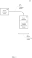
- the radiation therapy system 100 can include a particle source and accelerator or an energy source 110 (herein after referred to as a particle or energy source), a beam transport system 120, a beam applicator 130, an ionization chamber measurement system 140 and a patient positioning system 150.
- the radiation therapy system 100 typically also includes numerous other components such as vacuum components, power supply components, cooling components, mechanical support components, gantry components and the like, that are not necessary for an understanding of aspects of the present technology and therefore are not described further herein.
- the particle or energy source 110 can include a proton, electron or other particle source and a particle accelerator to accelerate a stream of protons, electrons or other particles.
- the particle or energy source 110 can include a photon, x-ray, gamma-ray or other energy source to generate a stream of photons, x-rays, gamma-rays or other energy.
- the stream of particles or energy can be output from the particle or energy source 110 onto the beam transport system 120.
- the beam transport system 120 can include various bending magnets, focus magnets and the like to direct the particles along the beam transport system 120.
- the beam applicator 130 can be configured to scan the particle stream within a target area to deliver specific amount of the dose to specific areas within the target.
- the beam applicator 130 can be a multi-leaf collimator configured to scan the energy stream within the target area.
- the beam applicator 130 can be any other device for directing the particle or energy stream to the target area.
- the ionization chamber measurement system 140 can be configured to measure the radiation rate, flux, beam fluence or the like of the particle stream before it is directed out to the target area of the patient.
- the patient positioning system 150 can include a table, chair or the like that moves in one or more directions to position patients.
- the ionization chamber measurement system 140 measures the charge from the number of ion pairs (e.g., electron and positively charged atom) created by incident radiation as the particle stream passes through the chamber.
- the ionization chamber can include two electrodes, a high-voltage source that applies a high-voltage potential between the two electrodes, and a circuit that measures a current generated by the ion pairs as the ionizing radiation of the particle streams passes through the gas in the chamber.
- the conventional art ionization chamber is calibrated to indicate a radiation rate, flux, beam fluence or the like based on the measured current for a particle stream having a given range of rate, flux, fluence or the like.
- a radiation therapy system 100 may be utilized for a first treatment modality, such as conventional radiotherapy, that delivers a dose rate of 0.6-180 cGy/sec.
- the radiation therapy system 100 may also be utilized for a second treatment modality, such as flash radiotherapy, that delivers a dose rate of 40-120 Gy/sec.
- a first treatment modality such as conventional radiotherapy
- a second treatment modality such as flash radiotherapy
- enabling the two very different treatment modalities currently requires an exchange of the ionization chamber measurement system 140. After the exchange, a long calibration process is required.
- the present invention provides an asymmetric dual-mode ionization chamber measurement system as defined in claim 1.
- the present invention provides an asymmetric dual-mode ionization measurement method as defined in claim 9.
- the present invention provides a radiation therapy system as defined in claim 14.
- Optional features are specified in the dependent claims.
- an ionization chamber measurement system can include a high-voltage supply, a readout plate, a first high-voltage plate, a second high-volage plate, a switch matrix and an ion charge measurement circuit.
- the high-voltage supply can be configured to generate a high-voltage potential.
- the first high-voltage plate can be disposed to form a first active volume between the first high-voltage plate and the readout plate.
- the second high-voltage plate can be disposed to form a second active volume between second high-voltage plate and the readout plate.
- the switch matrix can be configured to couple the high-voltage potential to the first high-voltage plate during a first mode, and to couple the high-voltage potential to the second high-voltage plate during a second mode.
- the ion charge measurement circuit can be coupled to the readout plate.
- a radiation stream can be configured to pass through the first and second active volumes.
- the ion charge measurement circuit can be configured to measure ions generated by the radiation stream passing through the first active volume during the first mode and to measure ions generated by the radiation stream passing through the second active volume during the second mode.
- a dual-mode ionization measurement method can include receiving an indication of a first mode or a second mode.
- a high-voltage potential can be coupled to a first high-voltage plate of an ionization chamber.
- the first high-voltage plate can be separated from a readout plate by a first gap.
- An ionizing radiation can be passed through the first gap of the ionization chamber when the first mode is indicated. Ion charge generated by the ionizing radiation passing through the first gap can be measured on the readout plate in the first mode.
- the high-voltage potential can be coupled to a second high-voltage plate of the ionization chamber.
- the second high-voltage plate can be separated from the readout plate by a second gap.
- An ionizing radiation can be passed through the second gap of the ionization chamber when the second mode is indicated. Ion charge generated by the ionizing radiation passing through the second gap can be measured on the readout plate in the second mode.
- a measurement of the radiation rate of the ionizing radiation can be determined as a function of the measured ion charge and the state of the ionization mode signal.
- a radiation therapy system can comprise:
- routines, modules, logic blocks, and other symbolic representations of operations on data within one or more electronic devices are presented in terms of routines, modules, logic blocks, and other symbolic representations of operations on data within one or more electronic devices.
- the descriptions and representations are the means used by those skilled in the art to most effectively convey the substance of their work to others skilled in the art.
- a routine, module, logic block and/or the like is herein, and generally, conceived to be a self-consistent sequence of processes or instructions leading to a desired result.
- the processes are those including physical manipulations of physical quantities.
- these physical manipulations take the form of electric or magnetic signals capable of being stored, transferred, compared and otherwise manipulated in an electronic device.
- these signals are referred to as data, bits, values, elements, symbols, characters, terms, numbers, strings, and/or the like with reference to embodiments of the present technology.
- the use of the disjunctive is intended to include the conjunctive.
- the use of definite or indefinite articles is not intended to indicate cardinality.
- a reference to “the” object or “a” object is intended to denote also one of a possible plurality of such objects.
- the use of the terms “comprises,” “comprising,” “includes,” “including” and the like specify the presence of stated elements, but do not preclude the presence or addition of one or more other elements and or groups thereof. It is also to be understood that although the terms first, second, etc. may be used herein to describe various elements, such elements should not be limited by these terms. These terms are used herein to distinguish one element from another.
- first element could be termed a second element, and similarly a second element could be termed a first element, without departing from the scope of embodiments.
- first element could be termed a second element, and similarly a second element could be termed a first element, without departing from the scope of embodiments.
- second element when an element is referred to as being “coupled” to another element, it may be directly or indirectly connected to the other element, or an intervening element may be present. In contrast, when an element is referred to as being “directly connected” to another element, there are not intervening elements present.
- the term “and or” includes any and all combinations of one or more of the associated elements. It is also to be understood that the phraseology and terminology used herein is for the purpose of description and should not be regarded as limiting.
- the asymmetric dual-mode ionization system can include a high-voltage supply 210, a switch matrix 220, an ionization chamber 230, a first high-voltage plate 240, a second high-voltage plate 250, a readout plate 260 and an ion charge measurement circuit 270.
- the asymmetric dual-mode ionization system can be configured for use in a first mode as illustrated in FIG. 2A , and a second mode as illustrated in FIG. 2B .
- the ionization chamber 230 can be configured for passage of the ionizing radiation through a gas in the ionization chamber 230.
- the ionizing radiation can be, but is not limited to, a proton stream, an electron stream, a photon stream or other similar radiation stream.
- the ionization chamber 230 is open to the atmosphere.
- the ionization chamber 230 can be sealed and filled with one or more specific gases, and can be maintained at a predetermined pressure and temperature.
- the first high-voltage plate 240, the second high-voltage plate 250 and the readout plate 260 can be contained within the structure of the ionization chamber 230.
- the first high-voltage plate 240, the second high-voltage plate 250 and the readout plate 260 can comprise the ionization chamber 230 itself.
- the first high-voltage plate 240 can be disposed to form a first active volume between the first high-voltage plate 240 and the readout plate 260.
- the second high-voltage plate 250 can be disposed to form a second active volume between the second high-voltage plate 250 and the readout plate 260.
- the readout plate 260 can be disposed between the first high-voltage plate 240 and the second high-voltage plate 250, wherein the first high-voltage plate 240 is separated from the readout plate 260 by a first predetermined gap (gap 1) and the second high-voltage plate 250 is separated from the readout plate 250 by a second predetermined gap (gap2).
- the first predetermined gap (gap1) can be greater than the second predetermined gap (gap2).
- the structure of the readout plate 260, and the first and second high-voltage plates 240, 250 within the ionization chamber 230 is also referred to herein as a double-stack dual-mode ionization chamber.
- the first high-voltage plate 240, the second high-voltage plate 250 and the readout plate 260 can be metal plates.
- the first high-voltage plate 240, the second high-voltage plate 250 and the readout plate 260 can be formed of a conductive layer disposed on an isolating substrate including, but not limited to, a polyimide layer.
- the first high-voltage plate 240, the second high-voltage plate 250 and the readout plate 260 can be of a given size and shape, including but not limited to round, square or rectangular.
- first high-voltage plate 240 and the second high-voltage plate 250 can be separated from the readout plate 260 by first and second predetermined gaps (gap1, gap2) within 0.1 millimeters (mm) to 10 centimeters (cm).
- first and second predetermined gaps may be smaller than 0.1 millimeters (mm) or larger than 10 centimeters (cm).
- Ionizing radiation 280 can be configured to pass through the first and second active volumes.
- the ionizing radiation 280 can pass through the first high-voltage plate 240, the first active volume, the readout plate 260, the second active volume, and then through the second high-voltage plate 250.
- the first active volume, or first predetermined gap (gap2) can be larger for a lower radiation rate so that a number of ion pairs generated by the lower radiation rate is within a given range.
- the second active volume, or second predetermined gap (gap2) can be smaller for a higher radiation rate so that the number of ion pairs generated by the higher radiation rate will be within the same given range.
- the switch matrix 220 can be configured to couple the high-voltage power supply 210 to the first high-voltage plate 240 during the first mode.
- the switch matrix 220 can be configured to couple the high-voltage power supply 210 to the second high-voltage plate 250 during the second mode.
- the switch matrix 220 can include a first switch configured to couple a high-voltage potential from the high-voltage power supply 210 to the first high-voltage plate 240 during the first mode and to the second high-voltage plate 250 during the second mode.
- a second switch of the switch matrix 220 can couple a ground potential to the first high-voltage plate 240 during the second mode, and to the second high-voltage plate 250 during the first mode.
- the switching can be automated and activated by an appropriate ionization mode control signal 290.
- the high voltage potential from the high-voltage power supply 210 applied to the first high-voltage plate 240 during the first mode and the second high-voltage plate 250 during the second mode can generate an electric field strength within the range of 100 to 1000 Volts per millimeter (V/mm) in the first and second active volumes during the respective first and second modes.
- ion pairs e.g., electrons and charged particles
- the free electrons and charged particles are accelerated toward the respective high-voltage plate 240, 250 and the readout plate where they are collected by the respective plates.
- the first mode can be characterized by a first radiation rate and the second mode can be characterized by a second radiation rate, wherein the second radiation rate is greater than the first radiation rate by an order of magnitude or greater.
- the first mode can be a conventional radiation therapy treatment modality such as, but not limited to, proton radiotherapy.
- the second mode can be a second radiation therapy treatment modality such as, but not limited to, flash proton radiotherapy.
- the first active volume, or the first predetermined gap may be determined based upon the radiation rate (e.g., dose rate) of the ionization radiation in the first mode, and the second active volume, or the second predetermined gap, may be determined based on the radiation rate (e.g., dose rate) of the ionizing radiation in the second mode.
- the radiation rate e.g., dose rate
- the second active volume, or the second predetermined gap may be determined based on the radiation rate (e.g., dose rate) of the ionizing radiation in the second mode.
- the ion charge measurement circuit 270 can be coupled to the readout plate 260 and configured to measure ions generated by the ionizing radiation 280 passing through the first active volume during the first mode, and to measure the ions generated by the ionizing radiation 280 passing through the second active volume during the second mode.
- the ion charge measurement circuit 270 can measure a current generated between the readout plate 260 and ground in a first mode.
- the ion charge measurement circuit 270 can measure the current generated between the readout plate 260 and ground.
- a lower ionization radiation rate (e.g., dose rates) generates a relatively low number of ion pairs from gas amplification in a given volume.
- ion pairs are generated corresponding to the ionizing radiation rate, and the resulting current can be measured by the ion charge measurement circuit 270.
- the measured current can be calibrated to indicate the ionizing radiation rate, beam flux, beam fluence or the like in the first mode.
- ion pairs are generated corresponding to the ionizing radiation, and the resulting current can be measured by the ion charge measurement circuit 270.
- the measured current can be calibrated to indicate the ionizing radiation rate, beam flux, beam fluence or the like in the first mode and the second mode.
- the measured current can be correlated to indicate the dose rate for both conventional proton radiotherapy and flash proton radiotherapy modalities without making changes to the ionization chamber 230 and/or ion charge measurement circuit 270. Therefore, the calibration can advantageously be performed once or on a periodic schedule, and not each time the mode changes, because there are no changes that need to be made with regard to ionization chamber 230 and/or ion charge measurement circuit 270.
- the dual-mode ionization measurement method can begin with receiving an indication of a first mode or a second mode, at 310.
- an ionization mode control signal indicating a first radiation therapy mode or a second radiation therapy mode, can be received.
- the ionization mode control signal can indicate a conventional proton radiotherapy modality or a flash proton radiotherapy modality.
- the ionization mode control signal can indicate a conventional electron radiotherapy modality or a flash electron radiotherapy modality.
- the ionization mode control signal can indicate a conventional photon radiotherapy modality or a flash photon radiotherapy modality.
- a high-voltage potential can be coupled to a first high-voltage plate when the first mode is indicated.
- the high-voltage potential can be coupled to the first high-voltage plate of an ionization chamber when the ionization mode control signal indicates the first radiation therapy mode, where the first high-voltage plate is separated from a readout plate by a first gap.
- the high-voltage potential can generate an electric field strength within a range of 100 to 1000 V/mm across the first gap.
- an ionizing radiation having a first range of rates can be passed through the ionization chamber when the first mode is indicated.
- a particle stream for a conventional proton radiotherapy modality can pass 0.6-180 cGy/sec of proton radiation through the ionization chamber when the ionization mode control signal indicates the conventional proton radiotherapy modality.
- free electrons and ions are generated by the ionizing radiation across the first gap.
- the free electrons and charged particles are collected by the respective first high-voltage plate and the readout plate.
- ion charge generated between the first high-voltage plate and the readout plate can be measured when the first mode is indicated.
- a current between the readout plate and ground can be measured when the ionizing radiation having a first range of rate passes through the ionization chamber in the first mode.
- the high-voltage potential can be coupled to a second high-voltage plate when the second mode is indicated, at 350.
- the high-voltage potential can be coupled to the second high-voltage plate of the ionization chamber when the ionization mode control signal indicates the second radiation therapy mode, wherein the second high-voltage plate is separated from the readout plate by a second gap.
- the high-voltage potential can generate an electric field strength within a range of 100 to 1000 V/mm across the second gap.
- an ionizing radiation having a second range of rates can be passed through the ionization chamber when the second mode is indicated.
- a particle stream for a flash proton radiotherapy modality can pass 40-120 Gy/sec of proton radiation through the ionization chamber when the ionization mode control signal indicates the flash proton radiotherapy modality.
- free electrons and charged particles are generated by the ionizing radiation across the second gap.
- the free electrons and charged particles are collected by the respective second high-voltage plate and the readout plate.
- ion charge generated between the second high-voltage plate and the readout plate can be measured when the second mode is indicated.
- a current between the readout plate and ground can be measured when the ionizing radiation having a second range of rates passes through the ionization chamber in the second mode.
- a measurement of the rate, flux density, beam fluence or the like of the ionizing radiation determined as a function of the measured ion charge and the corresponding first mode or second mode, can be output.
- the measured current for the given mode can be calibrated to indicate the ionizing radiation rate, flux density, beam fluence or the like. Accordingly, the measure current for example can be correlated to indicate the dose rate for both conventional proton radiotherapy and flash proton radiotherapy modalities without making changes each time the mode changes.
- the dual-mode ionization chamber measurement system 200 and method 300 can be utilized in the ionization chamber measurement system 150 of radiation therapy systems 100.
- the dual-mode ionization chamber measurement system 200 can be utilized to measure the dose rate or the like of a proton, electron or photon radiation stream of a radiation therapy system 100 that can switch between a conventional radiotherapy modality and a flash radiotherapy modality, without the need for recalibration after each switch between modalities.
- the particle or energy therapy system is just one possible application of the dual-mode ionization chamber measurement system in accordance with aspects of the present technology.
- Other possible applications can include nuclear magnetic resonance (NMR), magnetic resonance imaging (MRI), accelerator magnets for high energy physics (HEP) research, and nuclear fusion system.
- NMR nuclear magnetic resonance
- MRI magnetic resonance imaging
- HEP accelerator magnets for high energy physics
- nuclear fusion system nuclear fusion system.
- the dual-mode ionization chamber measurement system in accordance with aspects of the present technology can be further utilized in any other devices and methods where particles or energy streams that have significantly different ranges of radiation rates flux, beam fluence or the like need to be measured.
Landscapes
- Health & Medical Sciences (AREA)
- Life Sciences & Earth Sciences (AREA)
- Physics & Mathematics (AREA)
- Engineering & Computer Science (AREA)
- Biomedical Technology (AREA)
- Spectroscopy & Molecular Physics (AREA)
- Molecular Biology (AREA)
- High Energy & Nuclear Physics (AREA)
- General Physics & Mathematics (AREA)
- Nuclear Medicine, Radiotherapy & Molecular Imaging (AREA)
- Veterinary Medicine (AREA)
- Public Health (AREA)
- General Health & Medical Sciences (AREA)
- Animal Behavior & Ethology (AREA)
- Radiology & Medical Imaging (AREA)
- Pathology (AREA)
- Radiation-Therapy Devices (AREA)
Description
- Radiation Therapy (RT) utilizes ionizing radiation to control or kill tumors, or prevent the recurrence of tumors after other medical procedures. In cancerous tumors, ionizing radiation can damage the DNA of cancerous tissue leading to cellular death. Common types of radiation therapy include radiotherapy and radiosurgery. Radiotherapy is typically delivered in relatively smaller doses, five days a week for four to six weeks. Radiosurgery is typically delivered in relatively larger doses in one to five treatments. The number and frequency of treatments is typically referred to as the fractionation schedule. Conventional radiation therapy modalities typically deliver dose rates of 0.6-180 centigray per seconds (cGy/sec). An emerging radiotherapy modality, referred to as flash, is typically delivered at a high dose rate of 40-120 Gy/sec over a period of a few seconds or less in one treatment. Ionization chambers suitable i. a. for RT are disclosed in document
US3008051 A , for instance. - Referring now to
FIG. 1 , an exemplary radiation therapy system is shown. Theradiation therapy system 100 can include a particle source and accelerator or an energy source 110 (herein after referred to as a particle or energy source), abeam transport system 120, abeam applicator 130, an ionizationchamber measurement system 140 and apatient positioning system 150. Theradiation therapy system 100 typically also includes numerous other components such as vacuum components, power supply components, cooling components, mechanical support components, gantry components and the like, that are not necessary for an understanding of aspects of the present technology and therefore are not described further herein. - In one implementation, the particle or
energy source 110 can include a proton, electron or other particle source and a particle accelerator to accelerate a stream of protons, electrons or other particles. In another implementation, the particle orenergy source 110 can include a photon, x-ray, gamma-ray or other energy source to generate a stream of photons, x-rays, gamma-rays or other energy. The stream of particles or energy can be output from the particle orenergy source 110 onto thebeam transport system 120. In one implementation, thebeam transport system 120 can include various bending magnets, focus magnets and the like to direct the particles along thebeam transport system 120. In one implementation, thebeam applicator 130 can be configured to scan the particle stream within a target area to deliver specific amount of the dose to specific areas within the target. In another implementation, thebeam applicator 130 can be a multi-leaf collimator configured to scan the energy stream within the target area. In other implementation, thebeam applicator 130 can be any other device for directing the particle or energy stream to the target area. The ionizationchamber measurement system 140 can be configured to measure the radiation rate, flux, beam fluence or the like of the particle stream before it is directed out to the target area of the patient. Thepatient positioning system 150 can include a table, chair or the like that moves in one or more directions to position patients. - In one implementation, the ionization
chamber measurement system 140 measures the charge from the number of ion pairs (e.g., electron and positively charged atom) created by incident radiation as the particle stream passes through the chamber. In the conventional art, the ionization chamber can include two electrodes, a high-voltage source that applies a high-voltage potential between the two electrodes, and a circuit that measures a current generated by the ion pairs as the ionizing radiation of the particle streams passes through the gas in the chamber. The conventional art ionization chamber is calibrated to indicate a radiation rate, flux, beam fluence or the like based on the measured current for a particle stream having a given range of rate, flux, fluence or the like. However,radiation therapy systems 100 are now designed to deliver particle or energy streams for different treatment modalities that have significantly different ranges of radiation rates, flux, beam fluence or the like. For example, aradiation therapy system 100 may be utilized for a first treatment modality, such as conventional radiotherapy, that delivers a dose rate of 0.6-180 cGy/sec. Theradiation therapy system 100 may also be utilized for a second treatment modality, such as flash radiotherapy, that delivers a dose rate of 40-120 Gy/sec. However, enabling the two very different treatment modalities currently requires an exchange of the ionizationchamber measurement system 140. After the exchange, a long calibration process is required. Therefore, switching between two different treatment modalities, such as conventional radiotherapy and flash radiotherapy, requires that the treatment room be taken out of operation for a couple of hours. Accordingly, there is a need to improve the availability ofradiation therapy systems 100 when switching between different treatment modalities. - The invention and its advantageous embodiments are defined in the appended set of claims.
- The present technology may best be understood by referring to the following description and accompanying drawings that are used to illustrate embodiments of the present technology directed toward asymmetric dual-mode ionization systems.
- In one aspect, the present invention provides an asymmetric dual-mode ionization chamber measurement system as defined in claim 1. In another aspect, the present invention provides an asymmetric dual-mode ionization measurement method as defined in claim 9. In a further aspect, the present invention provides a radiation therapy system as defined in claim 14. Optional features are specified in the dependent claims.
- In one embodiment, an ionization chamber measurement system can include a high-voltage supply, a readout plate, a first high-voltage plate, a second high-volage plate, a switch matrix and an ion charge measurement circuit. The high-voltage supply can be configured to generate a high-voltage potential. The first high-voltage plate can be disposed to form a first active volume between the first high-voltage plate and the readout plate. The second high-voltage plate can be disposed to form a second active volume between second high-voltage plate and the readout plate. The switch matrix can be configured to couple the high-voltage potential to the first high-voltage plate during a first mode, and to couple the high-voltage potential to the second high-voltage plate during a second mode. The ion charge measurement circuit can be coupled to the readout plate. A radiation stream can be configured to pass through the first and second active volumes. The ion charge measurement circuit can be configured to measure ions generated by the radiation stream passing through the first active volume during the first mode and to measure ions generated by the radiation stream passing through the second active volume during the second mode.
- In another embodiment, a dual-mode ionization measurement method can include receiving an indication of a first mode or a second mode. In the first mode, a high-voltage potential can be coupled to a first high-voltage plate of an ionization chamber. The first high-voltage plate can be separated from a readout plate by a first gap. An ionizing radiation can be passed through the first gap of the ionization chamber when the first mode is indicated. Ion charge generated by the ionizing radiation passing through the first gap can be measured on the readout plate in the first mode. In the second mode, the high-voltage potential can be coupled to a second high-voltage plate of the ionization chamber. The second high-voltage plate can be separated from the readout plate by a second gap. An ionizing radiation can be passed through the second gap of the ionization chamber when the second mode is indicated. Ion charge generated by the ionizing radiation passing through the second gap can be measured on the readout plate in the second mode. A measurement of the radiation rate of the ionizing radiation can be determined as a function of the measured ion charge and the state of the ionization mode signal.
- In a further embodiment, a radiation therapy system can comprise:
- a particle or energy source;
- a beam transport system coupled to the particle or energy source;
- a beam applicator coupled to the beam transport system; and
- an ionization chamber measurement system coupled to the beam applicator, wherein the ionization chamber measurement system includes;
- a high-voltage supply configured to generate a high-voltage potential;
- an readout plate, wherein the readout plate is coupled to an ion charge measurement circuit;
- a first high-voltage plate disposed to form a first active volume between the first high-voltage plate and the readout plate, wherein a particle radiation stream is configured to pass through the first active volume;
- a second high-voltage plate disposed to form a second active volume between second high-voltage plate and the readout plate, and wherein the particle radiation stream is configured to pass through the second active volume;
- a switch matrix configured to couple the high-voltage potential to the first high-voltage plate during a first mode, and couple the high-voltage potential to the second high-voltage plate during a second mode; and
- the ion charge measurement circuit coupled to the readout plate and configured to measure ions generated by the ionizing radiation passing through the first active volume during the first mode and measure ions generated by the ionizing radiation passing through the second active volume during the second mode.
- This Summary is provided to introduce a selection of concepts in a simplified form that are further described below in the Detailed Description. This Summary is not intended to identify key features or essential features of the claimed subject matter, nor is it intended to be used to limit the scope of the claimed subject matter.
- Embodiments of the present technology are illustrated by way of example and not by way of limitation, in the figures of the accompanying drawings and in which like reference numerals refer to similar elements and in which:
-
FIG. 1 shows an exemplary particle therapy system. -
FIGS. 2A and 2B show an asymmetric dual-mode ionization system, in accordance with aspects of the present technology. -
FIG. 3 shows a dual-mode ionization measurement method, in accordance with aspects of the present technology. - Reference will now be made in detail to the embodiments of the present technology, examples of which are illustrated in the accompanying drawings. While the present technology will be described in conjunction with these embodiments, it will be understood that they are not intended to limit the technology to these embodiments. On the contrary, the invention is intended to cover alternatives, modifications and equivalents, which may be included within the scope of the invention as defined by the appended claims. Furthermore, in the following detailed description of the present technology, numerous specific details are set forth in order to provide a thorough understanding of the present technology. However, it is understood that the present technology may be practiced without these specific details. In other instances, well-known methods, procedures, components, and circuits have not been described in detail as not to unnecessarily obscure aspects of the present technology.
- Some embodiments of the present technology which follow are presented in terms of routines, modules, logic blocks, and other symbolic representations of operations on data within one or more electronic devices. The descriptions and representations are the means used by those skilled in the art to most effectively convey the substance of their work to others skilled in the art. A routine, module, logic block and/or the like, is herein, and generally, conceived to be a self-consistent sequence of processes or instructions leading to a desired result. The processes are those including physical manipulations of physical quantities. Usually, though not necessarily, these physical manipulations take the form of electric or magnetic signals capable of being stored, transferred, compared and otherwise manipulated in an electronic device. For reasons of convenience, and with reference to common usage, these signals are referred to as data, bits, values, elements, symbols, characters, terms, numbers, strings, and/or the like with reference to embodiments of the present technology.
- It should be borne in mind, however, that these terms are to be interpreted as referencing physical manipulations and quantities and are merely convenient labels and are to be interpreted further in view of terms commonly used in the art. Unless specifically stated otherwise as apparent from the following discussion, it is understood that through discussions of the present technology, discussions utilizing the terms such as "receiving," and/or the like, refer to the actions and processes of an electronic device such as an electronic computing device that manipulates and transforms data. The data is represented as physical (e.g., electronic) quantities within the electronic device's logic circuits, registers, memories and/or the like, and is transformed into other data similarly represented as physical quantities within the electronic device.
- In this application, the use of the disjunctive is intended to include the conjunctive. The use of definite or indefinite articles is not intended to indicate cardinality. In particular, a reference to "the" object or "a" object is intended to denote also one of a possible plurality of such objects. The use of the terms "comprises," "comprising," "includes," "including" and the like specify the presence of stated elements, but do not preclude the presence or addition of one or more other elements and or groups thereof. It is also to be understood that although the terms first, second, etc. may be used herein to describe various elements, such elements should not be limited by these terms. These terms are used herein to distinguish one element from another. For example, a first element could be termed a second element, and similarly a second element could be termed a first element, without departing from the scope of embodiments. It is also to be understood that when an element is referred to as being "coupled" to another element, it may be directly or indirectly connected to the other element, or an intervening element may be present. In contrast, when an element is referred to as being "directly connected" to another element, there are not intervening elements present. It is also to be understood that the term "and or" includes any and all combinations of one or more of the associated elements. It is also to be understood that the phraseology and terminology used herein is for the purpose of description and should not be regarded as limiting.
- Referring now to
FIGS. 2A and 2B , an asymmetric dual-mode ionization system, in accordance with aspects of the present technology, is shown. The asymmetric dual-mode ionization system can include a high-voltage supply 210, aswitch matrix 220, anionization chamber 230, a first high-voltage plate 240, a second high-voltage plate 250, areadout plate 260 and an ioncharge measurement circuit 270. The asymmetric dual-mode ionization system can be configured for use in a first mode as illustrated inFIG. 2A , and a second mode as illustrated inFIG. 2B . - The
ionization chamber 230 can be configured for passage of the ionizing radiation through a gas in theionization chamber 230. The ionizing radiation can be, but is not limited to, a proton stream, an electron stream, a photon stream or other similar radiation stream. In one implementation, theionization chamber 230 is open to the atmosphere. In other implementation, theionization chamber 230 can be sealed and filled with one or more specific gases, and can be maintained at a predetermined pressure and temperature. In one implementation, the first high-voltage plate 240, the second high-voltage plate 250 and thereadout plate 260 can be contained within the structure of theionization chamber 230. In another implementation, the first high-voltage plate 240, the second high-voltage plate 250 and thereadout plate 260 can comprise theionization chamber 230 itself. The first high-voltage plate 240 can be disposed to form a first active volume between the first high-voltage plate 240 and thereadout plate 260. The second high-voltage plate 250 can be disposed to form a second active volume between the second high-voltage plate 250 and thereadout plate 260. In one implementation, thereadout plate 260 can be disposed between the first high-voltage plate 240 and the second high-voltage plate 250, wherein the first high-voltage plate 240 is separated from thereadout plate 260 by a first predetermined gap (gap 1) and the second high-voltage plate 250 is separated from thereadout plate 250 by a second predetermined gap (gap2). The first predetermined gap (gap1) can be greater than the second predetermined gap (gap2). The structure of thereadout plate 260, and the first and second high-voltage plates ionization chamber 230 is also referred to herein as a double-stack dual-mode ionization chamber. In one implementation, the first high-voltage plate 240, the second high-voltage plate 250 and thereadout plate 260 can be metal plates. In another implementation, the first high-voltage plate 240, the second high-voltage plate 250 and thereadout plate 260 can be formed of a conductive layer disposed on an isolating substrate including, but not limited to, a polyimide layer. The first high-voltage plate 240, the second high-voltage plate 250 and thereadout plate 260 can be of a given size and shape, including but not limited to round, square or rectangular. In an exemplary implementation, the first high-voltage plate 240 and the second high-voltage plate 250 can be separated from thereadout plate 260 by first and second predetermined gaps (gap1, gap2) within 0.1 millimeters (mm) to 10 centimeters (cm). In other implementations the predetermined gaps may be smaller than 0.1 millimeters (mm) or larger than 10 centimeters (cm). - Ionizing
radiation 280 can be configured to pass through the first and second active volumes. For example, theionizing radiation 280 can pass through the first high-voltage plate 240, the first active volume, thereadout plate 260, the second active volume, and then through the second high-voltage plate 250. For a higher radiation rate more ion pairs will be generated (e.g., gas amplification) in a given volume as compared to a lower radiation rate. Therefore, the first active volume, or first predetermined gap (gap2), can be larger for a lower radiation rate so that a number of ion pairs generated by the lower radiation rate is within a given range. Similarly, the second active volume, or second predetermined gap (gap2), can be smaller for a higher radiation rate so that the number of ion pairs generated by the higher radiation rate will be within the same given range. - The
switch matrix 220 can be configured to couple the high-voltage power supply 210 to the first high-voltage plate 240 during the first mode. In a second mode, theswitch matrix 220 can be configured to couple the high-voltage power supply 210 to the second high-voltage plate 250 during the second mode. For example, theswitch matrix 220 can include a first switch configured to couple a high-voltage potential from the high-voltage power supply 210 to the first high-voltage plate 240 during the first mode and to the second high-voltage plate 250 during the second mode. A second switch of theswitch matrix 220 can couple a ground potential to the first high-voltage plate 240 during the second mode, and to the second high-voltage plate 250 during the first mode. The switching can be automated and activated by an appropriate ionizationmode control signal 290. In an exemplary implementation, the high voltage potential from the high-voltage power supply 210 applied to the first high-voltage plate 240 during the first mode and the second high-voltage plate 250 during the second mode can generate an electric field strength within the range of 100 to 1000 Volts per millimeter (V/mm) in the first and second active volumes during the respective first and second modes. As theionizing radiation 280 passes through the first or second active volumes during the respective first and second mode, ion pairs (e.g., electrons and charged particles) are generated in the respective active volume between the respective high-voltage plate readout plate 260. The free electrons and charged particles are accelerated toward the respective high-voltage plate - In one implementation, the first mode can be characterized by a first radiation rate and the second mode can be characterized by a second radiation rate, wherein the second radiation rate is greater than the first radiation rate by an order of magnitude or greater. In one implementation, the first mode can be a conventional radiation therapy treatment modality such as, but not limited to, proton radiotherapy. The second mode can be a second radiation therapy treatment modality such as, but not limited to, flash proton radiotherapy. The first active volume, or the first predetermined gap, may be determined based upon the radiation rate (e.g., dose rate) of the ionization radiation in the first mode, and the second active volume, or the second predetermined gap, may be determined based on the radiation rate (e.g., dose rate) of the ionizing radiation in the second mode.
- The ion
charge measurement circuit 270 can be coupled to thereadout plate 260 and configured to measure ions generated by theionizing radiation 280 passing through the first active volume during the first mode, and to measure the ions generated by theionizing radiation 280 passing through the second active volume during the second mode. For example, the ioncharge measurement circuit 270 can measure a current generated between thereadout plate 260 and ground in a first mode. In a second mode, the ioncharge measurement circuit 270 can measure the current generated between thereadout plate 260 and ground. In the first mode, a lower ionization radiation rate (e.g., dose rates) generates a relatively low number of ion pairs from gas amplification in a given volume. Therefore, in the large active volume in the first mode, ion pairs are generated corresponding to the ionizing radiation rate, and the resulting current can be measured by the ioncharge measurement circuit 270. The measured current can be calibrated to indicate the ionizing radiation rate, beam flux, beam fluence or the like in the first mode. Similarly, in the small active volume in the second mode, ion pairs are generated corresponding to the ionizing radiation, and the resulting current can be measured by the ioncharge measurement circuit 270. The measured current can be calibrated to indicate the ionizing radiation rate, beam flux, beam fluence or the like in the first mode and the second mode. For example, the measured current can be correlated to indicate the dose rate for both conventional proton radiotherapy and flash proton radiotherapy modalities without making changes to theionization chamber 230 and/or ioncharge measurement circuit 270. Therefore, the calibration can advantageously be performed once or on a periodic schedule, and not each time the mode changes, because there are no changes that need to be made with regard toionization chamber 230 and/or ioncharge measurement circuit 270. - Referring now to
FIG. 3 , a dual-mode ionization measurement method, in accordance with aspects of the present technology, is shown. The dual-mode ionization measurement method can begin with receiving an indication of a first mode or a second mode, at 310. In one implementation, an ionization mode control signal, indicating a first radiation therapy mode or a second radiation therapy mode, can be received. For example, the ionization mode control signal can indicate a conventional proton radiotherapy modality or a flash proton radiotherapy modality. In another example, the ionization mode control signal can indicate a conventional electron radiotherapy modality or a flash electron radiotherapy modality. In yet another example, the ionization mode control signal can indicate a conventional photon radiotherapy modality or a flash photon radiotherapy modality. - At 320, a high-voltage potential can be coupled to a first high-voltage plate when the first mode is indicated. In one implementation, the high-voltage potential can be coupled to the first high-voltage plate of an ionization chamber when the ionization mode control signal indicates the first radiation therapy mode, where the first high-voltage plate is separated from a readout plate by a first gap. In an exemplary implementation, the high-voltage potential can generate an electric field strength within a range of 100 to 1000 V/mm across the first gap. At 330, an ionizing radiation having a first range of rates can be passed through the ionization chamber when the first mode is indicated. For example, a particle stream for a conventional proton radiotherapy modality can pass 0.6-180 cGy/sec of proton radiation through the ionization chamber when the ionization mode control signal indicates the conventional proton radiotherapy modality. In one implementation, free electrons and ions are generated by the ionizing radiation across the first gap. The free electrons and charged particles are collected by the respective first high-voltage plate and the readout plate. At 340, ion charge generated between the first high-voltage plate and the readout plate can be measured when the first mode is indicated. In one implementation, a current between the readout plate and ground can be measured when the ionizing radiation having a first range of rate passes through the ionization chamber in the first mode.
- Alternatively, the high-voltage potential can be coupled to a second high-voltage plate when the second mode is indicated, at 350. In one implementation, the high-voltage potential can be coupled to the second high-voltage plate of the ionization chamber when the ionization mode control signal indicates the second radiation therapy mode, wherein the second high-voltage plate is separated from the readout plate by a second gap. In an exemplary implementation, the high-voltage potential can generate an electric field strength within a range of 100 to 1000 V/mm across the second gap. At 360, an ionizing radiation having a second range of rates can be passed through the ionization chamber when the second mode is indicated. For example, a particle stream for a flash proton radiotherapy modality can pass 40-120 Gy/sec of proton radiation through the ionization chamber when the ionization mode control signal indicates the flash proton radiotherapy modality. In one implementation, free electrons and charged particles are generated by the ionizing radiation across the second gap. The free electrons and charged particles are collected by the respective second high-voltage plate and the readout plate. At 370, ion charge generated between the second high-voltage plate and the readout plate can be measured when the second mode is indicated. In one implementation, a current between the readout plate and ground can be measured when the ionizing radiation having a second range of rates passes through the ionization chamber in the second mode.
- At 380, a measurement of the rate, flux density, beam fluence or the like of the ionizing radiation, determined as a function of the measured ion charge and the corresponding first mode or second mode, can be output. In one implementation, the measured current for the given mode can be calibrated to indicate the ionizing radiation rate, flux density, beam fluence or the like. Accordingly, the measure current for example can be correlated to indicate the dose rate for both conventional proton radiotherapy and flash proton radiotherapy modalities without making changes each time the mode changes.
- Referring again to
FIG. 1 , the dual-mode ionizationchamber measurement system 200 andmethod 300 can be utilized in the ionizationchamber measurement system 150 ofradiation therapy systems 100. For example, the dual-mode ionizationchamber measurement system 200 can be utilized to measure the dose rate or the like of a proton, electron or photon radiation stream of aradiation therapy system 100 that can switch between a conventional radiotherapy modality and a flash radiotherapy modality, without the need for recalibration after each switch between modalities. - The particle or energy therapy system is just one possible application of the dual-mode ionization chamber measurement system in accordance with aspects of the present technology. Other possible applications can include nuclear magnetic resonance (NMR), magnetic resonance imaging (MRI), accelerator magnets for high energy physics (HEP) research, and nuclear fusion system. The dual-mode ionization chamber measurement system in accordance with aspects of the present technology can be further utilized in any other devices and methods where particles or energy streams that have significantly different ranges of radiation rates flux, beam fluence or the like need to be measured.
- The foregoing descriptions of specific embodiments of the present technology have been presented for purposes of illustration and description. They are not intended to be exhaustive or to limit the present technology to the precise forms disclosed, and obviously many modifications and variations are possible in light of the above teaching. The embodiments were chosen and described in order to best explain the principles of the present technology and its practical application, to thereby enable others skilled in the art to best utilize the present technology and various embodiments with various modifications as are suited to the particular use contemplated. It is intended that the scope of the invention be defined by the claims appended hereto.
Claims (15)
- An asymmetric dual-mode ionization chamber measurement system comprising:a high-voltage supply configured to generate a high-voltage potential;an ionization chamber (230) including:a readout plate (260);a first high-voltage plate (240) disposed to form a first active volume between the first high-voltage plate and the readout plate, wherein a radiation stream is configured to pass through the first active volume; anda second high-voltage plate (250) disposed to form a second active volume between the second high-voltage plate and the readout plate, and wherein the radiation stream is configured to pass through the second active volume;a switch matrix (220) configured to couple the high-voltage potential to the first high-voltage plate during a first mode, and couple the high-voltage potential to the second high-voltage plate during a second mode; andan ion charge measurement circuit (270) coupled to the readout plate and configured to measure ions generated by the radiation stream passing through the first active volume during the first mode and to measure ions generated by the radiation stream passing through the second active volume during the second mode.
- The asymmetric dual-mode ionization chamber measurement system of Claim 1, wherein:a range of rates of the radiation stream in the second mode is greater than a range of rates of the radiation stream in the first mode; andthe first active volume is greater than the second active volume.
- The asymmetric dual-mode ionization chamber measurement system of Claim 1 or 2, wherein:the radiation stream comprises a proton radiation stream;the first mode comprises a conventional proton radiotherapy modality; andthe second mode comprises a flash proton radiotherapy modality.
- The asymmetric dual-mode ionization chamber measurement system of Claim 1 or 2, wherein:the radiation stream comprises an electron radiation stream;the first mode comprises a conventional electron radiotherapy modality; andthe second mode comprises a flash electron radiotherapy modality.
- The asymmetric dual-mode ionization chamber measurement system of Claim 1 or 2, wherein:the radiation stream comprises a photon radiation stream;the first mode comprises a conventional photon radiotherapy modality; andthe second mode comprises a flash photon radiotherapy modality.
- The asymmetric dual-mode ionization chamber measurement system of any one of Claims 1 to 5, wherein the switch matrix comprises:a first switch configured to couple the high-voltage potential to the first high-voltage plate during the first mode and couple the high-voltage potential to the second high-voltage plate during the second mode; anda second switch configured to couple a ground potential to the second high-voltage plate during the first mode and couple the ground potential to the first high-voltage plate during the second mode.
- The asymmetric dual-mode ionization chamber measurement system of any one of Claims 1 to 6, wherein the ion charge measurement circuit comprises a current measurement circuit configured to measure a current generated by ions flowing between the readout plate and a ground potential during the first mode and by the ions flowing between the readout plate and the ground potential during the second mode.
- The asymmetric dual-mode ionization chamber measurement system of any one of Claims 1 to 7, wherein the high-voltage potential generates an electric field strength between 100 to 1000 V/mm across the first active volume during the first mode and across the second active volume during the second mode.
- An asymmetric dual-mode ionization measurement method comprising:receiving an indication of a first mode or a second mode;coupling a high-voltage potential to a first high-voltage plate of an ionization chamber when the first mode is indicated, wherein the first high-voltage plate is separated from an readout plate by a first gap;coupling the high-voltage potential to a second high-voltage plate of the ionization chamber when the second mode is indicated, wherein the second high-voltage plate is separated from the readout plate by a second gap;passing an ionizing radiation having a first density range through the ionization chamber when the first mode is indicated;passing an ionizing radiation having a second density range through the ionization chamber when the second mode is indicated; andmeasuring ion charge on the readout plate when the ionization mode control signal is in the first state, wherein the ion charge is generated by the ionizing radiation passing through the ionization chamber;measuring the ion charge on the readout plate when the ionization mode control signal is in the second state, wherein the ion charge is generated by the ionizing radiation passing through the ionization chamber; andoutputting a measurement of the radiation rate of the ionizing radiation determined as a function of the measured ion charge and the state of the ionization mode signal.
- The asymmetric dual-mode ionization measurement method according to Claim 9, wherein:the ionizing radiation comprises proton radiation;the first mode comprises a conventional proton radiotherapy modality; andthe second mode comprises a flash proton radiotherapy modality.
- The asymmetric dual-mode ionization measurement method according to Claim 9, wherein:the ionizing radiation comprises electron radiation;the first mode comprises a conventional electron radiotherapy modality; andthe second mode comprises a flash electron radiotherapy modality.
- The asymmetric dual-mode ionization measurement method according to Claim 9, wherein:the ionizing radiation comprises photon radiation;the first mode comprises a conventional photon radiotherapy modality; andthe second mode comprises a flash photon radiotherapy modality.
- The asymmetric dual-mode ionization measurement method according to Claim 9, 10, 11 or 12, further comprising:coupling a ground potential to the second high-voltage plate of the ionization chamber when the first mode is indicated; andcoupling the ground potential to a first high-voltage plate of the ionization chamber when the second mode is indicated.
- A radiation therapy system comprising:a particle or energy source;a beam transport system coupled to the particle or energy source;a beam applicator coupled to the beam transport system; andan asymmetric dual-mode ionization chamber measurement system as defined in any one of claims 1 to 8;wherein:the ionization chamber measurement system is coupled to the beam applicator; andthe readout plate is coupled to an ion charge measurement circuit.
- The radiation therapy system of Claim 14, wherein at least one of:the particle or energy source comprises a proton source and accelerator;the particle or energy source comprises an electron source and accelerator;the particle or energy source comprises a photon source;the ion charge measurement circuit comprises a current measurement circuit;the readout plate, the first high-voltage plate and second high-voltage plate comprise conductive plates; andthe readout plate, the first high-voltage plate and second high-voltage plate comprise plates of a conductive layer on an isolating substrate.
Applications Claiming Priority (1)
| Application Number | Priority Date | Filing Date | Title |
|---|---|---|---|
| US17/219,542 US11534626B2 (en) | 2021-03-31 | 2021-03-31 | Asymmetric dual-mode ionization systems and methods |
Publications (2)
| Publication Number | Publication Date |
|---|---|
| EP4067942A1 EP4067942A1 (en) | 2022-10-05 |
| EP4067942B1 true EP4067942B1 (en) | 2023-08-02 |
Family
ID=81324898
Family Applications (1)
| Application Number | Title | Priority Date | Filing Date |
|---|---|---|---|
| EP22165887.5A Active EP4067942B1 (en) | 2021-03-31 | 2022-03-31 | Asymmetric dual-mode ionization systems and methods |
Country Status (3)
| Country | Link |
|---|---|
| US (2) | US11534626B2 (en) |
| EP (1) | EP4067942B1 (en) |
| CN (1) | CN115144887B (en) |
Families Citing this family (2)
| Publication number | Priority date | Publication date | Assignee | Title |
|---|---|---|---|---|
| US11534626B2 (en) * | 2021-03-31 | 2022-12-27 | Varian Medical Systems Particle Therapy Gmbh & Co. Kg | Asymmetric dual-mode ionization systems and methods |
| CN120132247B (en) * | 2025-05-15 | 2025-08-19 | 合肥中科离子医学技术装备有限公司 | Dual-mode accurate regulation and control method and device for proton treatment system |
Family Cites Families (18)
| Publication number | Priority date | Publication date | Assignee | Title |
|---|---|---|---|---|
| GB890741A (en) | 1957-05-20 | 1962-03-07 | Mullard Ltd | Improvements in or relating to radiation meters |
| AU6574694A (en) | 1993-04-28 | 1994-11-21 | University Of Surrey | Radiation detectors |
| FR2739941B1 (en) | 1995-10-11 | 1997-11-14 | Commissariat Energie Atomique | HIGH RESOLUTION POSITION DETECTOR FOR HIGH IONIZING PARTICLE FLOWS |
| SE514472C2 (en) * | 1999-04-14 | 2001-02-26 | Xcounter Ab | Radiation detector and apparatus for use in radiography |
| JP4499262B2 (en) * | 2000-09-07 | 2010-07-07 | アロカ株式会社 | Ionization chamber type radiation detector and ionization chamber inspection method |
| US7432510B2 (en) * | 2005-09-13 | 2008-10-07 | In Hwan Yeo | Dosimeter based on a gas electron multiplier for dose measurements of therapeutic radiation |
| US7700925B2 (en) * | 2007-12-28 | 2010-04-20 | Varian Semiconductor Equipment Associates, Inc. | Techniques for providing a multimode ion source |
| EP2088613B1 (en) * | 2008-02-08 | 2015-10-14 | ICT, Integrated Circuit Testing Gesellschaft für Halbleiterprüftechnik mbH | Use of a dual mode gas field ion source |
| US7812321B2 (en) * | 2008-06-11 | 2010-10-12 | Varian Semiconductor Equipment Associates, Inc. | Techniques for providing a multimode ion source |
| US9437093B2 (en) * | 2011-10-06 | 2016-09-06 | Microchip Technology Incorporated | Differential current measurements to determine ION current in the presence of leakage current |
| US9408286B1 (en) * | 2013-09-03 | 2016-08-02 | Sandia Corporation | Short pulse neutron generator |
| US10183181B2 (en) | 2015-07-22 | 2019-01-22 | Viewray Technologies, Inc. | Ion chamber for radiation measurement |
| GB2563194B (en) * | 2016-04-21 | 2020-08-05 | Waters Technologies Corp | Dual mode ionization device |
| US10751553B2 (en) * | 2016-06-28 | 2020-08-25 | Hitachi, Ltd. | Radiation therapy apparatus |
| US9978554B1 (en) * | 2017-01-26 | 2018-05-22 | Varian Semiconductor Equipment Associates, Inc. | Dual cathode ion source |
| US20210210326A1 (en) * | 2018-05-28 | 2021-07-08 | Shimadzu Corporation | Analytical device |
| CN110556281B (en) * | 2018-06-01 | 2024-01-23 | 日新离子机器株式会社 | Ion beam irradiation apparatus |
| US11534626B2 (en) * | 2021-03-31 | 2022-12-27 | Varian Medical Systems Particle Therapy Gmbh & Co. Kg | Asymmetric dual-mode ionization systems and methods |
-
2021
- 2021-03-31 US US17/219,542 patent/US11534626B2/en active Active
-
2022
- 2022-03-10 CN CN202210230533.3A patent/CN115144887B/en active Active
- 2022-03-31 EP EP22165887.5A patent/EP4067942B1/en active Active
- 2022-12-23 US US18/088,242 patent/US11944845B2/en active Active
Also Published As
| Publication number | Publication date |
|---|---|
| EP4067942A1 (en) | 2022-10-05 |
| CN115144887A (en) | 2022-10-04 |
| US11534626B2 (en) | 2022-12-27 |
| US20220314030A1 (en) | 2022-10-06 |
| CN115144887B (en) | 2025-09-19 |
| US20230125731A1 (en) | 2023-04-27 |
| US11944845B2 (en) | 2024-04-02 |
Similar Documents
| Publication | Publication Date | Title |
|---|---|---|
| JP6292813B2 (en) | Radiation measurement apparatus, particle beam therapy apparatus equipped with the same, and dose distribution calculation method for particle beam | |
| US11944845B2 (en) | Asymmetric dual-mode ionization systems and methods | |
| Kutsaev et al. | Compact X-Band electron linac for radiotherapy and security applications | |
| US11596806B2 (en) | Dose rate monitor, system and method | |
| CN103977506A (en) | Method and device for proton tomography | |
| US12318634B2 (en) | Monitor for high dose rate electron therapy, system and method | |
| US9545526B1 (en) | System and method for projection image tracking of tumors during radiotherapy | |
| EP3815744A1 (en) | Radiotherapy apparatus for animal | |
| Akulinichev et al. | Possibilities of proton FLASH therapy on the accelerator at the Russian Academy of Sciences’ Institute for Nuclear Research | |
| CN115015997B (en) | A large-area online neutron detector and detection method | |
| Boucher et al. | Compact, inexpensive X-band linacs as radioactive isotope source replacements | |
| Yamada et al. | HIMAC and medical accelerator projects in Japan | |
| Klimpki | Pre-report on the dissertation Development of a treatment verification system for continuous scanning in proton therapy | |
| Arora | An investigation of the polarity effects in small field based on the orientation of the micro ionization chamber | |
| Pugatcha et al. | Hybrid and Metal Microdetector Systems for measuring in real time spatial distribution of charged particles and X-rays beams | |
| Wilk-Kohlbrecher et al. | Session 9. Radiation therapy II–Particle therapy I | |
| Miller | Characterization and optimization of microionization chambers | |
| Blais | Modified fermi-eyges electron scattering in tissue equivalent media | |
| Ahmed | Dosimetric Measurements in the Medical Linear Accelerator at (RICK) In Khartoum State | |
| Reynard | Rotational total skin electron irradiation (RTSEI) with a 6 MeV electron linear accelerator | |
| Zinov'ev et al. | Possibilities of JINR synchrophasotron application to medical and biological purposes | |
| Sagia | Silicon microdosimetry in hadron therapy fields | |
| Fan | Characterization of an Amorphous Silicon Electronic Portal Imaging Device for use as | |
| Souza | Comparative study of the parameters associated with quality control and absorbed dose in linear accelerators with (FF) and without (FFF) flattening filter | |
| Partridge | Joint Department of Physics, The Institute of Cancer Research & The Royal |
Legal Events
| Date | Code | Title | Description |
|---|---|---|---|
| PUAI | Public reference made under article 153(3) epc to a published international application that has entered the european phase |
Free format text: ORIGINAL CODE: 0009012 |
|
| STAA | Information on the status of an ep patent application or granted ep patent |
Free format text: STATUS: THE APPLICATION HAS BEEN PUBLISHED |
|
| AK | Designated contracting states |
Kind code of ref document: A1 Designated state(s): AL AT BE BG CH CY CZ DE DK EE ES FI FR GB GR HR HU IE IS IT LI LT LU LV MC MK MT NL NO PL PT RO RS SE SI SK SM TR |
|
| STAA | Information on the status of an ep patent application or granted ep patent |
Free format text: STATUS: REQUEST FOR EXAMINATION WAS MADE |
|
| 17P | Request for examination filed |
Effective date: 20221025 |
|
| RBV | Designated contracting states (corrected) |
Designated state(s): AL AT BE BG CH CY CZ DE DK EE ES FI FR GB GR HR HU IE IS IT LI LT LU LV MC MK MT NL NO PL PT RO RS SE SI SK SM TR |
|
| GRAP | Despatch of communication of intention to grant a patent |
Free format text: ORIGINAL CODE: EPIDOSNIGR1 |
|
| STAA | Information on the status of an ep patent application or granted ep patent |
Free format text: STATUS: GRANT OF PATENT IS INTENDED |
|
| RIC1 | Information provided on ipc code assigned before grant |
Ipc: A61N 5/10 20060101ALI20230302BHEP Ipc: H01J 47/02 20060101ALI20230302BHEP Ipc: G01T 1/185 20060101AFI20230302BHEP |
|
| INTG | Intention to grant announced |
Effective date: 20230324 |
|
| RIN1 | Information on inventor provided before grant (corrected) |
Inventor name: SCHUMACHER, BIRGER Inventor name: BUSOLD, SIMON Inventor name: SCHEDLER, MANUEL |
|
| GRAS | Grant fee paid |
Free format text: ORIGINAL CODE: EPIDOSNIGR3 |
|
| GRAA | (expected) grant |
Free format text: ORIGINAL CODE: 0009210 |
|
| STAA | Information on the status of an ep patent application or granted ep patent |
Free format text: STATUS: THE PATENT HAS BEEN GRANTED |
|
| AK | Designated contracting states |
Kind code of ref document: B1 Designated state(s): AL AT BE BG CH CY CZ DE DK EE ES FI FR GB GR HR HU IE IS IT LI LT LU LV MC MK MT NL NO PL PT RO RS SE SI SK SM TR |
|
| REG | Reference to a national code |
Ref country code: GB Ref legal event code: FG4D |
|
| REG | Reference to a national code |
Ref country code: CH Ref legal event code: EP |
|
| REG | Reference to a national code |
Ref country code: DE Ref legal event code: R096 Ref document number: 602022000268 Country of ref document: DE |
|
| REG | Reference to a national code |
Ref country code: IE Ref legal event code: FG4D |
|
| REG | Reference to a national code |
Ref country code: LT Ref legal event code: MG9D |
|
| REG | Reference to a national code |
Ref country code: NL Ref legal event code: MP Effective date: 20230802 |
|
| REG | Reference to a national code |
Ref country code: AT Ref legal event code: MK05 Ref document number: 1595420 Country of ref document: AT Kind code of ref document: T Effective date: 20230802 |
|
| PG25 | Lapsed in a contracting state [announced via postgrant information from national office to epo] |
Ref country code: GR Free format text: LAPSE BECAUSE OF FAILURE TO SUBMIT A TRANSLATION OF THE DESCRIPTION OR TO PAY THE FEE WITHIN THE PRESCRIBED TIME-LIMIT Effective date: 20231103 |
|
| PG25 | Lapsed in a contracting state [announced via postgrant information from national office to epo] |
Ref country code: IS Free format text: LAPSE BECAUSE OF FAILURE TO SUBMIT A TRANSLATION OF THE DESCRIPTION OR TO PAY THE FEE WITHIN THE PRESCRIBED TIME-LIMIT Effective date: 20231202 |
|
| PG25 | Lapsed in a contracting state [announced via postgrant information from national office to epo] |
Ref country code: SE Free format text: LAPSE BECAUSE OF FAILURE TO SUBMIT A TRANSLATION OF THE DESCRIPTION OR TO PAY THE FEE WITHIN THE PRESCRIBED TIME-LIMIT Effective date: 20230802 Ref country code: RS Free format text: LAPSE BECAUSE OF FAILURE TO SUBMIT A TRANSLATION OF THE DESCRIPTION OR TO PAY THE FEE WITHIN THE PRESCRIBED TIME-LIMIT Effective date: 20230802 Ref country code: PT Free format text: LAPSE BECAUSE OF FAILURE TO SUBMIT A TRANSLATION OF THE DESCRIPTION OR TO PAY THE FEE WITHIN THE PRESCRIBED TIME-LIMIT Effective date: 20231204 Ref country code: NO Free format text: LAPSE BECAUSE OF FAILURE TO SUBMIT A TRANSLATION OF THE DESCRIPTION OR TO PAY THE FEE WITHIN THE PRESCRIBED TIME-LIMIT Effective date: 20231102 Ref country code: NL Free format text: LAPSE BECAUSE OF FAILURE TO SUBMIT A TRANSLATION OF THE DESCRIPTION OR TO PAY THE FEE WITHIN THE PRESCRIBED TIME-LIMIT Effective date: 20230802 Ref country code: LV Free format text: LAPSE BECAUSE OF FAILURE TO SUBMIT A TRANSLATION OF THE DESCRIPTION OR TO PAY THE FEE WITHIN THE PRESCRIBED TIME-LIMIT Effective date: 20230802 Ref country code: LT Free format text: LAPSE BECAUSE OF FAILURE TO SUBMIT A TRANSLATION OF THE DESCRIPTION OR TO PAY THE FEE WITHIN THE PRESCRIBED TIME-LIMIT Effective date: 20230802 Ref country code: IS Free format text: LAPSE BECAUSE OF FAILURE TO SUBMIT A TRANSLATION OF THE DESCRIPTION OR TO PAY THE FEE WITHIN THE PRESCRIBED TIME-LIMIT Effective date: 20231202 Ref country code: HR Free format text: LAPSE BECAUSE OF FAILURE TO SUBMIT A TRANSLATION OF THE DESCRIPTION OR TO PAY THE FEE WITHIN THE PRESCRIBED TIME-LIMIT Effective date: 20230802 Ref country code: GR Free format text: LAPSE BECAUSE OF FAILURE TO SUBMIT A TRANSLATION OF THE DESCRIPTION OR TO PAY THE FEE WITHIN THE PRESCRIBED TIME-LIMIT Effective date: 20231103 Ref country code: FI Free format text: LAPSE BECAUSE OF FAILURE TO SUBMIT A TRANSLATION OF THE DESCRIPTION OR TO PAY THE FEE WITHIN THE PRESCRIBED TIME-LIMIT Effective date: 20230802 Ref country code: AT Free format text: LAPSE BECAUSE OF FAILURE TO SUBMIT A TRANSLATION OF THE DESCRIPTION OR TO PAY THE FEE WITHIN THE PRESCRIBED TIME-LIMIT Effective date: 20230802 |
|
| PG25 | Lapsed in a contracting state [announced via postgrant information from national office to epo] |
Ref country code: PL Free format text: LAPSE BECAUSE OF FAILURE TO SUBMIT A TRANSLATION OF THE DESCRIPTION OR TO PAY THE FEE WITHIN THE PRESCRIBED TIME-LIMIT Effective date: 20230802 |
|
| PG25 | Lapsed in a contracting state [announced via postgrant information from national office to epo] |
Ref country code: ES Free format text: LAPSE BECAUSE OF FAILURE TO SUBMIT A TRANSLATION OF THE DESCRIPTION OR TO PAY THE FEE WITHIN THE PRESCRIBED TIME-LIMIT Effective date: 20230802 |
|
| PG25 | Lapsed in a contracting state [announced via postgrant information from national office to epo] |
Ref country code: SM Free format text: LAPSE BECAUSE OF FAILURE TO SUBMIT A TRANSLATION OF THE DESCRIPTION OR TO PAY THE FEE WITHIN THE PRESCRIBED TIME-LIMIT Effective date: 20230802 Ref country code: RO Free format text: LAPSE BECAUSE OF FAILURE TO SUBMIT A TRANSLATION OF THE DESCRIPTION OR TO PAY THE FEE WITHIN THE PRESCRIBED TIME-LIMIT Effective date: 20230802 Ref country code: ES Free format text: LAPSE BECAUSE OF FAILURE TO SUBMIT A TRANSLATION OF THE DESCRIPTION OR TO PAY THE FEE WITHIN THE PRESCRIBED TIME-LIMIT Effective date: 20230802 Ref country code: EE Free format text: LAPSE BECAUSE OF FAILURE TO SUBMIT A TRANSLATION OF THE DESCRIPTION OR TO PAY THE FEE WITHIN THE PRESCRIBED TIME-LIMIT Effective date: 20230802 Ref country code: DK Free format text: LAPSE BECAUSE OF FAILURE TO SUBMIT A TRANSLATION OF THE DESCRIPTION OR TO PAY THE FEE WITHIN THE PRESCRIBED TIME-LIMIT Effective date: 20230802 Ref country code: CZ Free format text: LAPSE BECAUSE OF FAILURE TO SUBMIT A TRANSLATION OF THE DESCRIPTION OR TO PAY THE FEE WITHIN THE PRESCRIBED TIME-LIMIT Effective date: 20230802 Ref country code: SK Free format text: LAPSE BECAUSE OF FAILURE TO SUBMIT A TRANSLATION OF THE DESCRIPTION OR TO PAY THE FEE WITHIN THE PRESCRIBED TIME-LIMIT Effective date: 20230802 |
|
| REG | Reference to a national code |
Ref country code: DE Ref legal event code: R097 Ref document number: 602022000268 Country of ref document: DE |
|
| PG25 | Lapsed in a contracting state [announced via postgrant information from national office to epo] |
Ref country code: IT Free format text: LAPSE BECAUSE OF FAILURE TO SUBMIT A TRANSLATION OF THE DESCRIPTION OR TO PAY THE FEE WITHIN THE PRESCRIBED TIME-LIMIT Effective date: 20230802 |
|
| PLBE | No opposition filed within time limit |
Free format text: ORIGINAL CODE: 0009261 |
|
| STAA | Information on the status of an ep patent application or granted ep patent |
Free format text: STATUS: NO OPPOSITION FILED WITHIN TIME LIMIT |
|
| 26N | No opposition filed |
Effective date: 20240503 |
|
| PG25 | Lapsed in a contracting state [announced via postgrant information from national office to epo] |
Ref country code: SI Free format text: LAPSE BECAUSE OF FAILURE TO SUBMIT A TRANSLATION OF THE DESCRIPTION OR TO PAY THE FEE WITHIN THE PRESCRIBED TIME-LIMIT Effective date: 20230802 |
|
| PG25 | Lapsed in a contracting state [announced via postgrant information from national office to epo] |
Ref country code: BG Free format text: LAPSE BECAUSE OF FAILURE TO SUBMIT A TRANSLATION OF THE DESCRIPTION OR TO PAY THE FEE WITHIN THE PRESCRIBED TIME-LIMIT Effective date: 20230802 |
|
| PG25 | Lapsed in a contracting state [announced via postgrant information from national office to epo] |
Ref country code: LU Free format text: LAPSE BECAUSE OF NON-PAYMENT OF DUE FEES Effective date: 20240331 |
|
| PG25 | Lapsed in a contracting state [announced via postgrant information from national office to epo] |
Ref country code: MC Free format text: LAPSE BECAUSE OF FAILURE TO SUBMIT A TRANSLATION OF THE DESCRIPTION OR TO PAY THE FEE WITHIN THE PRESCRIBED TIME-LIMIT Effective date: 20230802 |
|
| PG25 | Lapsed in a contracting state [announced via postgrant information from national office to epo] |
Ref country code: MC Free format text: LAPSE BECAUSE OF FAILURE TO SUBMIT A TRANSLATION OF THE DESCRIPTION OR TO PAY THE FEE WITHIN THE PRESCRIBED TIME-LIMIT Effective date: 20230802 Ref country code: LU Free format text: LAPSE BECAUSE OF NON-PAYMENT OF DUE FEES Effective date: 20240331 Ref country code: BG Free format text: LAPSE BECAUSE OF FAILURE TO SUBMIT A TRANSLATION OF THE DESCRIPTION OR TO PAY THE FEE WITHIN THE PRESCRIBED TIME-LIMIT Effective date: 20230802 |
|
| REG | Reference to a national code |
Ref country code: BE Ref legal event code: MM Effective date: 20240331 |
|
| PG25 | Lapsed in a contracting state [announced via postgrant information from national office to epo] |
Ref country code: BE Free format text: LAPSE BECAUSE OF NON-PAYMENT OF DUE FEES Effective date: 20240331 |
|
| PG25 | Lapsed in a contracting state [announced via postgrant information from national office to epo] |
Ref country code: FR Free format text: LAPSE BECAUSE OF NON-PAYMENT OF DUE FEES Effective date: 20240331 |
|
| PG25 | Lapsed in a contracting state [announced via postgrant information from national office to epo] |
Ref country code: IE Free format text: LAPSE BECAUSE OF NON-PAYMENT OF DUE FEES Effective date: 20240331 |
|
| PG25 | Lapsed in a contracting state [announced via postgrant information from national office to epo] |
Ref country code: IE Free format text: LAPSE BECAUSE OF NON-PAYMENT OF DUE FEES Effective date: 20240331 Ref country code: FR Free format text: LAPSE BECAUSE OF NON-PAYMENT OF DUE FEES Effective date: 20240331 Ref country code: BE Free format text: LAPSE BECAUSE OF NON-PAYMENT OF DUE FEES Effective date: 20240331 |
|
| PGFP | Annual fee paid to national office [announced via postgrant information from national office to epo] |
Ref country code: DE Payment date: 20250520 Year of fee payment: 4 |
|
| PG25 | Lapsed in a contracting state [announced via postgrant information from national office to epo] |
Ref country code: CY Free format text: LAPSE BECAUSE OF FAILURE TO SUBMIT A TRANSLATION OF THE DESCRIPTION OR TO PAY THE FEE WITHIN THE PRESCRIBED TIME-LIMIT; INVALID AB INITIO Effective date: 20220331 |
|
| REG | Reference to a national code |
Ref country code: CH Ref legal event code: H13 Free format text: ST27 STATUS EVENT CODE: U-0-0-H10-H13 (AS PROVIDED BY THE NATIONAL OFFICE) Effective date: 20251024 |
|
| PG25 | Lapsed in a contracting state [announced via postgrant information from national office to epo] |
Ref country code: TR Free format text: LAPSE BECAUSE OF FAILURE TO SUBMIT A TRANSLATION OF THE DESCRIPTION OR TO PAY THE FEE WITHIN THE PRESCRIBED TIME-LIMIT Effective date: 20230802 |
|
| PG25 | Lapsed in a contracting state [announced via postgrant information from national office to epo] |
Ref country code: CH Free format text: LAPSE BECAUSE OF NON-PAYMENT OF DUE FEES Effective date: 20250331 |