EP4067912A1 - Capacitance reference line update method, and chip and capacitance measurement apparatus - Google Patents
Capacitance reference line update method, and chip and capacitance measurement apparatus Download PDFInfo
- Publication number
- EP4067912A1 EP4067912A1 EP21867867.0A EP21867867A EP4067912A1 EP 4067912 A1 EP4067912 A1 EP 4067912A1 EP 21867867 A EP21867867 A EP 21867867A EP 4067912 A1 EP4067912 A1 EP 4067912A1
- Authority
- EP
- European Patent Office
- Prior art keywords
- frame
- feature
- capacitance data
- raw
- capacitance
- Prior art date
- Legal status (The legal status is an assumption and is not a legal conclusion. Google has not performed a legal analysis and makes no representation as to the accuracy of the status listed.)
- Granted
Links
Images


Classifications
-
- H—ELECTRICITY
- H03—ELECTRONIC CIRCUITRY
- H03K—PULSE TECHNIQUE
- H03K17/00—Electronic switching or gating, i.e. not by contact-making and –breaking
- H03K17/94—Electronic switching or gating, i.e. not by contact-making and –breaking characterised by the way in which the control signals are generated
- H03K17/945—Proximity switches
- H03K17/955—Proximity switches using a capacitive detector
-
- G—PHYSICS
- G01—MEASURING; TESTING
- G01D—MEASURING NOT SPECIALLY ADAPTED FOR A SPECIFIC VARIABLE; ARRANGEMENTS FOR MEASURING TWO OR MORE VARIABLES NOT COVERED IN A SINGLE OTHER SUBCLASS; TARIFF METERING APPARATUS; MEASURING OR TESTING NOT OTHERWISE PROVIDED FOR
- G01D5/00—Mechanical means for transferring the output of a sensing member; Means for converting the output of a sensing member to another variable where the form or nature of the sensing member does not constrain the means for converting; Transducers not specially adapted for a specific variable
- G01D5/12—Mechanical means for transferring the output of a sensing member; Means for converting the output of a sensing member to another variable where the form or nature of the sensing member does not constrain the means for converting; Transducers not specially adapted for a specific variable using electric or magnetic means
- G01D5/14—Mechanical means for transferring the output of a sensing member; Means for converting the output of a sensing member to another variable where the form or nature of the sensing member does not constrain the means for converting; Transducers not specially adapted for a specific variable using electric or magnetic means influencing the magnitude of a current or voltage
- G01D5/24—Mechanical means for transferring the output of a sensing member; Means for converting the output of a sensing member to another variable where the form or nature of the sensing member does not constrain the means for converting; Transducers not specially adapted for a specific variable using electric or magnetic means influencing the magnitude of a current or voltage by varying capacitance
- G01D5/2403—Mechanical means for transferring the output of a sensing member; Means for converting the output of a sensing member to another variable where the form or nature of the sensing member does not constrain the means for converting; Transducers not specially adapted for a specific variable using electric or magnetic means influencing the magnitude of a current or voltage by varying capacitance by moving plates, not forming part of the capacitor itself, e.g. shields
-
- H—ELECTRICITY
- H03—ELECTRONIC CIRCUITRY
- H03K—PULSE TECHNIQUE
- H03K17/00—Electronic switching or gating, i.e. not by contact-making and –breaking
- H03K17/94—Electronic switching or gating, i.e. not by contact-making and –breaking characterised by the way in which the control signals are generated
- H03K17/96—Touch switches
- H03K17/962—Capacitive touch switches
-
- H—ELECTRICITY
- H03—ELECTRONIC CIRCUITRY
- H03K—PULSE TECHNIQUE
- H03K2217/00—Indexing scheme related to electronic switching or gating, i.e. not by contact-making or -breaking covered by H03K17/00
- H03K2217/94—Indexing scheme related to electronic switching or gating, i.e. not by contact-making or -breaking covered by H03K17/00 characterised by the way in which the control signal is generated
- H03K2217/9401—Calibration techniques
- H03K2217/94031—Calibration involving digital processing
Definitions
- Embodiments of the present disclosure relate to the technical field of capacitance detection, and in particular to a method for updating a capacitance reference, a chip, and a capacitance detection apparatus.
- a capacitance detection apparatus can identify whether a human body or other conductors are approaching based on a capacitance value variation.
- Fig. 1 shows a schematic structural diagram of a typical capacitance detection apparatus.
- the capacitance detection apparatus includes: a sensor 101, an amplifier (AMP) 102, and an analog to digital converter (ADC) 103.
- AMP amplifier
- ADC analog to digital converter
- the sensor 101 may output a detected capacitance signal to the amplifier 102, to input an amplified capacitance signal to the analog to digital converter 103, thereby obtaining a raw capacitance signal RawData.
- a difference value between the raw capacitance signal RawData and a reference signal Ref may be computed to obtain a capacitance variation signal Diff; and a signal value of the capacitance variation signal Diff may be compared with a preset threshold to identify whether a human body or other conductors are approaching or moving away from the capacitance detection apparatus.
- the reference signal Ref is a signal outputted from the capacitance detection apparatus when there is no additional input from a human body or other conductors.
- Fig. 2 shows a schematic fluctuation diagram of a raw capacitance signal RawData outputted from the above typical capacitance detection apparatus; as can be seen therefrom, at a moment t1, a signal value of the raw capacitance signal RawData is equal to a signal value of a reference signal Ref, indicating that no human body or other conductors are approaching the capacitance detection apparatus; at a moment t2, a signal value of the raw capacitance signal RawData reaches a proximity threshold ON th , indicating that a human body or other conductors have approached the capacitance detection apparatus; and at a moment t3, the signal value of the raw capacitance signal RawData decreases to an off threshold OFF th , indicating that the human body or other conductors are moving away from the capacitance detection apparatus.
- the event includes: a human body or other conductors approach the capacitance detection apparatus, or a human body or other conductors move away from the capacitance detection apparatus.
- Ref(n) is a current n-th frame of reference value of the reference signal Ref
- Ref(n-1) is an (n-1)-th frame of reference value of the reference signal Ref
- RawData(n) is the current n-th frame of raw capacitance data of the raw capacitance signal RawData
- Coef x is a filter coefficient.
- the size of the filter coefficient Coef x can affect smoothness and delayed response of the Ref(n), and the size of the filter coefficient Coef x is adjusted such that the higher the smoothness is, the greater the delayed response is; and the smaller the delayed response is, the lower the smoothness is.
- the reference updating method weighs current sampled RawData(n) and last outputted Ref(n-1), to update partial data of the raw capacitance signal RawData to a new reference signal Ref.
- this method will partially update both valid data and noise in the raw capacitance signal RawData to the reference signal Ref, resulting in noise jitter in the computed capacitance variation signal Diff. If it is intended to reduce jitter of the reference signal Ref, greater delayed response will be caused. Therefore, the above reference updating method is difficult to be adapted to an application scenario that is more sensitive to noise interference and delayed response.
- Embodiments of the present disclosure provide a method for updating a capacitance reference, a chip, and a capacitance detection apparatus, for effectively updating the capacitance reference value in real time, and reducing the impacts of noise jitter and delayed response on the capacitance detection performance.
- an embodiment of the present disclosure provides a method for updating a capacitance reference.
- the method is applied to a capacitance detection apparatus, and includes:
- the feature value Feature(n) corresponding to the n-th frame of raw capacitance data is set based on the n-th frame of raw capacitance data RawData(n) and the (n-M)-th frame of raw capacitance data RawData(n-M); and the size of the feature value Feature(n) is compared with the size of the first threshold, thereby determining whether there is an additional input from a human body or other conductors on the capacitance detection apparatus.
- the capacitance detection apparatus When the feature value Feature(n) corresponding to the n-th frame of raw capacitance data of is less than the first threshold Thr 1 , and the capacitance variation Diff(n) is less than the proximity threshold Thr on , it means that there is no additional input from a human body or other conductors on the capacitance detection apparatus, i.e., the capacitance detection apparatus is in an empty state.
- the reference value Ref(n) corresponding to the n-th frame of raw capacitance data is set to be equal to the n-th frame of raw capacitance data RawData(n) or the (n-1)-th frame of raw capacitance data RawData(n-1), thereby offsetting partial noise in a capacitance variation signal Diff, enabling the capacitance variation signal Diff to track the fluctuations of the raw capacitance signal RawData in real time, and reducing the impacts of noise jitter and delayed response on the capacitance detection performance.
- the reference value Ref(n) corresponding to the n-th frame of raw capacitance data is determined based on the reference value Ref(n-1) corresponding to the (n-1)-th frame of raw capacitance data.
- the reference value Ref(n) corresponding to the n-th frame of raw capacitance data is determined based on the feature value Feature(n) corresponding to the n-th frame of raw capacitance data, a feature value Feature(n-1) corresponding to the (n-1)-th frame of raw capacitance data, the reference value Ref(n-1) corresponding to the (n-1)-th frame of raw capacitance data, and a reference value Ref(n-2) corresponding to an (n-2)-th frame of raw capacitance data outputted from the capacitance detection apparatus; where the second threshold Thr 2 is used for determining whether the conductor is gradually disconnected from contact with the capacitance detection apparatus
- the reference value Ref(n) corresponding to the n-th frame of raw capacitance data is determined based on the reference value Ref(n-1) corresponding to the (n-1)-th frame of raw capacitance data.
- the determining, based on the n-th frame of raw capacitance data RawData(n) and the (n-M)-th frame of raw capacitance data RawData(n-M) outputted from the capacitance detection apparatus, the feature value Feature(n) corresponding to the n-th frame of raw capacitance data further includes: determining a difference value between the n-th frame of raw capacitance data RawData(n) and the (n-M)-th frame of raw capacitance data RawData(n-M) as the feature value Feature(n) corresponding to the n-th frame of raw capacitance data.
- the determining, when the feature value Feature(n) corresponding to the n-th frame of raw capacitance data is less than the first threshold Thr 1 , and the capacitance variation Diff(n) is less than the proximity threshold Thr on , the n-th frame of raw capacitance data RawData(n) or the (n-1)-th frame of raw capacitance data RawData(n-1) as the reference value Ref(n) corresponding to the n-th frame of raw capacitance data further includes: determining a minimum value of the n-th frame of raw capacitance data RawData(n) and the (n-1)-th frame of raw capacitance data RawData(n-1) as the reference value Ref(n) corresponding to the n-th frame of raw capacitance data.
- the determining, when the feature value Feature(n) corresponding to the n-th frame of raw capacitance data is greater than or equal to the first threshold Thr 1 , and the capacitance variation Diff(n) is less than the proximity threshold Thr on , the reference value Ref(n) corresponding to the n-th frame of raw capacitance data based on the reference value Ref(n-1) corresponding to the (n-1)-th frame of raw capacitance data further includes:
- the determining, when the feature value Feature(n) corresponding to the n-th frame of raw capacitance data is greater than or equal to the second threshold Thr 2 , and is less than or equal to the first threshold Thr 1 , and the capacitance variation Diff(n) is greater than or equal to the proximity threshold Thr on , the reference value Ref(n) corresponding to the n-th frame of raw capacitance data based on the feature value Feature(n) corresponding to the n-th frame of raw capacitance data, the feature value Feature(n-1) corresponding to the (n-1)-th frame of raw capacitance data, the reference value Ref(n-1) corresponding to the (n-1)-th frame of raw capacitance data, and the reference value Ref(n-2) corresponding to the (n-2)-th frame of raw capacitance data outputted from the capacitance detection apparatus further includes:
- a value of the second variation Diff_Ref(n-1) is not zero.
- the determining, when the feature value Feature(n) corresponding to the n-th frame of raw capacitance data is less than the second threshold Thr 2 or greater than the first threshold Thr 1 , and the capacitance variation Diff(n) is greater than or equal to the proximity threshold Thr on , the reference value Ref(n) corresponding to the n-th frame of raw capacitance data based on the reference value Ref(n-1) corresponding to the (n-1)-th frame of raw capacitance data further includes:
- an embodiment of the present disclosure provides a chip, including a processor and a memory, where the memory is coupled to the processor;
- an embodiment of the present disclosure provides a capacitance detection apparatus, including the chip according to the second aspect.
- an embodiment of the present disclosure provides a computer readable storage medium configured to store a computer program, where the computer program causes a computer to execute the method for updating a capacitance reference according to the first aspect or any one alternative implementation in the first aspect.
- the chip according to the second aspect, the capacitance detection apparatus according to the third aspect, and the computer readable storage medium according to the fourth aspect provided above are all configured to execute the corresponding method provided above, and therefore, the beneficial effects in the corresponding methods provided above may be referred to for the beneficial effects to be achieved whereby. The description will not be repeated here.
- each step may be performed in the specified order, or each step may be performed substantially simultaneously, each step may be performed in a reverse order, or each step may be performed in a different order.
- first and second are only used for distinguishing between similar objects, and cannot be understood as indicating or implying relative importance or implicitly indicating the number of indicated technical features.
- features defined with “first,” “second,” or the like may explicitly or implicitly include one or more of the features.
- Step S101 determining, based on an n-th frame of raw capacitance data RawData(n) and an (n-M)-th frame of raw capacitance data RawData(n-M) outputted from the capacitance detection apparatus, a feature value Feature(n) corresponding to the n-th frame of raw capacitance data.
- the feature value Feature(n) corresponding to the n-th frame of raw capacitance data may indicate a different stage in a process of a conductor (a human body or other conductors) approaching or moving away from the capacitance detection apparatus.
- Step S102 computing a difference value between the n-th frame of raw capacitance data RawData(n) and a reference value Ref(n-1) corresponding to an (n-1)-th frame of raw capacitance data outputted from the capacitance detection apparatus, to obtain a capacitance variation Diff(n).
- a capacitance variation corresponding to the n-th frame of raw capacitance data may be predicted based on the capacitance variation Diff(n), thereby determining a moving state of the conductor.
- the moving state may include: having approached the capacitance detection appearance (approached state) and not approaching the capacitance detection apparatus (non-approaching state).
- the capacitance variation corresponding to the n-th frame of raw capacitance data is the difference value between the n-th frame of raw capacitance data RawData(n) and the corresponding reference value Ref(n) thereof, i.e., RawData(n)-Ref(n), which may be used for indicating a current capacitance variation caused by the human body or other conductors.
- Step S103a determining, when the feature value Feature(n) corresponding to the n-th frame of raw capacitance data is less than a first threshold Thr 1 , and the capacitance variation Diff(n) is less than a proximity threshold Thr on , the n-th frame of raw capacitance data RawData(n) or the (n-1)-th frame of raw capacitance data RawData(n-1) as a reference value Ref(n) corresponding to the n-th frame of raw capacitance data.
- the proximity threshold Thr on may be used for determining whether the conductor has approached the capacitance detection apparatus; and the first threshold Thr 1 may be used for determining whether there is an additional input from the conductor on the capacitance detection apparatus.
- the capacitance variation Diff(n) may be compared with the proximity threshold Thr on , to determine whether the conductor has approached the capacitance detection apparatus, i.e., determine the moving state of the conductor. Specifically, if the capacitance variation Diff(n) reaches the proximity threshold Thr on , i.e., is greater than or equal to the proximity threshold Thr on , it may be determined that the conductor is in the approached state; and if the capacitance variation Diff(n) does not reach the proximity threshold Thr on , i.e., is less than the proximity threshold Thr on , it may be determined that the conductor is in a non-approaching state.
- the size of the proximity threshold Thr on may be generated by machine learning based on training data.
- the training data may include, but is not limited to, a corresponding capacitance variation Diff(n) when different types of conductors come in contact with the capacitance detection apparatus to different extents and a corresponding capacitance variation Diff(n) when there are different distances between different types of conductors and the capacitance detection apparatus.
- the size of the proximity threshold Thr on may also be adjusted accordingly based on subsequent actual applications of a user, thereby more accurately distinguishing whether the human body or other conductors have approached the capacitance detection apparatus, and better adapting to different application scenarios.
- Step S103b determining, when the feature value Feature(n) corresponding to the n-th frame of raw capacitance data is greater than or equal to the first threshold Thr 1 , and the capacitance variation Diff(n) is less than the proximity threshold Thr on , the reference value Ref(n) corresponding to the n-th frame of raw capacitance data based on the reference value Ref(n-1) corresponding to the (n-1)-th frame of raw capacitance data.
- Step S103c determining, when the feature value Feature(n) corresponding to the n-th frame of raw capacitance data is greater than or equal to a second threshold Thr 2 , and is less than or equal to the first threshold Thr 1 , and the capacitance variation Diff(n) is greater than or equal to the proximity threshold Thr on , the reference value Ref(n) corresponding to the n-th frame of raw capacitance data based on the feature value Feature(n) corresponding to the n-th frame of raw capacitance data, a feature value Feature(n-1) corresponding to the (n-1)-th frame of raw capacitance data, the reference value Ref(n-1) corresponding to the (n-1)-th frame of raw capacitance data, and a reference value Ref(n-2) corresponding to an (n-2)-th frame of raw capacitance data outputted from the capacitance detection apparatus.
- the second threshold Thr 2 is less than the first threshold Thr 1 .
- the second threshold Thr 2 may be used for determining whether the conductor is gradually disconnected from contact with the capacitance detection apparatus, and specifically may be used for further determining whether a moving trend of the conductor in the approached state is to maintain stable contact with the capacitance detection apparatus or to start to move away from the capacitance detection apparatus.
- Step S103d determining, when the feature value Feature(n) corresponding to the n-th frame of raw capacitance data is less than the second threshold Thr 2 or greater than the first threshold Thr 1 , and the capacitance variation Diff(n) is greater than or equal to the proximity threshold Thr on , the reference value Ref(n) corresponding to the n-th frame of raw capacitance data based on the reference value Ref(n-1) corresponding to the (n-1)-th frame of raw capacitance data.
- n is a positive integer greater than 2
- M is a positive integer greater than or equal to 1
- M ⁇ n a value of Ref (1) or Ref (2) may be set to be equal to a signal value of a raw capacitance signal outputted from the capacitance detection apparatus when there is no additional input from a human body or other conductors.
- setting of the first threshold Thr 1 may also be generated by machine learning based on training data.
- the training data may include, but is not limited to: a capacitance variation when there is no additional input from a human body or other conductors on the capacitance detection apparatus, a capacitance variation when a human body or other conductors start to approach the capacitance detection apparatus, and a capacitance variation when a human body or other conductors start to move away from the capacitance detection apparatus.
- the second threshold Thr 2 may be set as a negative value, and its absolute value may be from 2 to 3 times as much as the first threshold Thr 1 .
- the feature value Feature(n) is set based on the n-th frame of raw capacitance data RawData(n) and the (n-M)-th frame of raw capacitance data RawData(n-M), the size of the feature value Feature(n) is compared with the size of a preset threshold, a process of a human body or other conductors approaching or moving away from the capacitance detection apparatus may be classified into different stages, and a corresponding capacitance reference updating approach may be set based on different moving states (approached/non-approaching) and moving trends (approaching, maintaining contact, moving away) of a conductor in each stage, thereby effectively updating the reference value in real time.
- Feature(n) ⁇ Thr 1 and Diff(n) ⁇ Thr on may indicate that there is no additional input caused by a conductor on the capacitance detection apparatus, including: no conductor starts to approach the capacitance detection apparatus, and a conductor has moved away from the capacitance detection apparatus; and the raw capacitance data RawData(n) in this stage only indicates a capacitance variation caused by an environmental noise, such that this stage may be referred to as a noise stage.
- Feature(n) ⁇ Thr 1 and Diff(n) ⁇ Thr on may indicate that a conductor is slowly/rapidly approaching the capacitance detection apparatus, but the conductor is still in a non-approaching state, such that this stage may be referred to as a pre-approaching stage.
- Thr 2 ⁇ Feature(n) ⁇ Thr 1 and Diff(n) ⁇ Thr on may indicate that a conductor maintains stable contact with the capacitance detection apparatus, and has reached a most approaching state; and Feature(n)> Thr 1 or Feature(n) ⁇ Thr 2 and Diff(n) ⁇ Thr on means that the conductor is in the approached state and is further approaching the capacitance detection apparatus, or is gradually disconnected from contact with the capacitance detection apparatus, i.e., starts to leave from the capacitance detection apparatus.
- the two stages may be referred to as an approaching stage.
- the determining, based on the n-th frame of raw capacitance data RawData(n) and the (n-M)-th frame of raw capacitance data RawData(n-M) outputted from the capacitance detection apparatus, the feature value Feature(n) corresponding to the n-th frame of raw capacitance data further includes: determining a difference value between the n-th frame of raw capacitance data RawData(n) and the (n-M)-th frame of raw capacitance data RawData(n-M) as the feature value Feature(n) corresponding to the n-th frame of raw capacitance data.
- a value of M may be set based on an actual application scenario and to-be-achieved application objective, and may be at least 1. Further, the smaller the value of M is, the better the timeliness of the capacitor reference update is, but the higher the computing workload is.
- the determining, when the feature value Feature(n) corresponding to the n-th frame of raw capacitance data is less than the first threshold Thr 1 , and the capacitance variation Diff(n) is less than the proximity threshold Thr on , the n-th frame of raw capacitance data RawData(n) or the (n-1)-th frame of raw capacitance data RawData(n-1) as the reference value Ref(n) corresponding to the n-th frame of raw capacitance data further includes: determining a minimum value of the n-th frame of raw capacitance data RawData(n) and the (n-1)-th frame of raw capacitance data RawData(n-1) as the reference value Ref(n) corresponding to the n-th frame of raw capacitance data.
- This reference updating approach may enable a noise in a capacitance variation signal Diff in this stage to merely have a one-way variation, thereby effectively reducing a noise of a reverse variation in the capacitance variation signal Diff, can reduce a noise variance in the capacitance variation signal Diff in this stage by half compared with first-order hysteresis filtering commonly used in the prior art, will not consume a valid signal component in the capacitance variation signal Diff, and in addition, may also enable the reference signal Ref to track the fluctuations of the raw capacitance signal RawData in real time, thereby reducing the impacts of noise jitter and delayed response on the capacitance detection performance.
- the determining, when the feature value Feature(n) corresponding to the n-th frame of raw capacitance data is greater than or equal to the first threshold Thr 1 , and the capacitance variation Diff(n) is less than the proximity threshold Thr on , the reference value Ref(n) corresponding to the n-th frame of raw capacitance data based on the reference value Ref(n-1) corresponding to the (n-1)-th frame of raw capacitance data further includes: When the feature value Feature(n) corresponding to the n-th frame of raw capacitance data is greater than or equal to the first threshold Thr 1 , and is less than a third threshold Thr 3 , and the capacitance variation Diff(n) is less than the proximity threshold Thr on , a sum of the reference value Ref(n-1) corresponding to the (n-1)-th frame of raw capacitance data and a first correction value Corr 1 is determined as the reference value Ref(n) corresponding to the n-
- the third threshold Thr 3 may be used for determining an extent to which the conductor is approaching the capacitance detection apparatus, and the third threshold Thr 3 is greater than the first threshold Thr 1 ; and the first correction value Corr 1 and the second correction value Corr 2 may be used for characterizing an offset of a reference value caused by an environmental factor in a corresponding stage, respectively.
- this reference updating approach can reduce the reference drift noise caused by an environmental factor such as temperature, improve the signal-to-noise ratio of the capacitance variation signal Diff, and update the reference signal Ref in real time, thereby reducing the impacts of noise jitter and delayed response on the capacitance detection performance.
- the pre-approaching stage may be further divided into two sub-stages, and a human body or other conductors approach the capacitance detection apparatus to different extents in the two sub-stages.
- a human body or other conductors approach the capacitance detection apparatus to different extents in the two sub-stages.
- the approaching extent in the second pre-approaching stage is higher than that in the first pre-approaching stage.
- the first correction value Corr 1 may be set to be about 20% of the proximity threshold Thr on
- the second correction value Corr 2 may be set to be equal to the first correction value Corr 1 or slightly smaller than the first correction value Corr 1 .
- the third threshold Thr 3 may be set as an opposite number of the second threshold Thr 2 , i.e., 2 to 3 times as much as the first threshold Thr 1 .
- the determining, when the feature value Feature(n) corresponding to the n-th frame of raw capacitance data is greater than or equal to the second threshold Thr 2 , and is less than or equal to the first threshold Thr 1 , and the capacitance variation Diff(n) is greater than or equal to the proximity threshold Thr on , the reference value Ref(n) corresponding to the n-th frame of raw capacitance data based on the feature value Feature(n) corresponding to the n-th frame of raw capacitance data, the feature value Feature(n-1) corresponding to the (n-1)-th frame of raw capacitance data, the reference value Ref(n-1) corresponding to the (n-1)-th frame of raw capacitance data, and the reference value Ref(n-2) corresponding to the (n-2)-th frame of raw capacitance data outputted from the capacitance detection apparatus further includes:
- the second variation Diff_Ref(n-1) ⁇ 0. If in this stage, Ref(n-1) is equal to Ref(n-2), the second variation Diff_Ref(n-1) may be set as a non-zero constant value, for example, may be set to be equal to a value of a non-zero second variation Diff_Ref(n-1) in a previous frame.
- the conductor steadily maintains contact with the capacitance detection apparatus, and is in the most approaching state.
- the conductor generally shakes to a certain extent or has a temperature difference from a sensor in the capacitance detection apparatus, which tends to cause abnormal jitter variation of the raw capacitance signal RawData, further makes the capacitance variation signal Diff have an obvious noise component, and affects the accuracy of the capacitance detection result, while the updating the capacitance reference value in real time by the above approach can extract the jitter variation in the raw capacitance signal RawData in a process of the conductor maintaining continuous and stable contact with the capacitance detection apparatus, and superimpose the jitter variation to the reference signal Ref, thereby reducing low-frequency noise in the capacitance variation signal Diff, and effectively reducing the probability of misrecognition or missed recognition of an event.
- the determining, when the feature value Feature(n) corresponding to the n-th frame of raw capacitance data is less than the second threshold Thr 2 or greater than the first threshold Thr 1 , and the capacitance variation Diff(n) is greater than or equal to the proximity threshold Thr on , the reference value Ref(n) corresponding to the n-th frame of raw capacitance data based on the reference value Ref(n-1) corresponding to the (n-1)-th frame of raw capacitance data further includes: determining, when the feature value Feature(n) corresponding to the n-th frame of raw capacitance data is greater than the first threshold Thr 1 , and the capacitance variation Diff(n) is greater than or equal to the proximity threshold Thr on , the sum of the reference value Ref(n-1) corresponding to the (n-1)-th frame of raw capacitance data and the second correction value Corr 2 as the reference value Ref(n) corresponding to the n-th frame of raw capacitance
- the third correction value Corr 3 may be used for characterizing an offset of a reference value caused by an environmental factor in a corresponding stage. Specifically, the third correction value Corr 3 may be set based on an actual application scenario, and may be equal to the first correction value Corr 1 and the second correction value Corr 2 , or slightly smaller than the first correction value Corr 1 .
- this stage may be further divided into two sub-stages.
- Feature(n)> Thr 1 and Diff(n) ⁇ Thr on means that the conductor is in an approached state and is further approaching the capacitance detection apparatus.
- Feature(n) ⁇ Thr 2 and Diff(n) ⁇ Thr on means that the conductor is in the approached state, but is gradually disconnected from contact with the capacitance detection apparatus, i.e., starts to leave from the capacitance detection apparatus.
- the above reference updating approach can reduce the reference drift noise caused by an environmental factor such as temperature, improve the signal-to-noise ratio of the capacitance variation signal Diff, and enable the reference signal Ref to promptly track the variation of the raw capacitance signal RawData in real time, thereby reducing the impacts of noise jitter and delayed response on the capacitance detection performance.
- a schematic fluctuation diagram of a raw capacitance signal and a feature signal in a process of a conductor approaching and moving away provided in an embodiment of the present disclosure is shown. It can be seen that by comparing the Feature(n) with the first threshold Thr 1 , the second threshold Thr 2 , and the third threshold Thr 3 , the process of the conductor approaching and moving away from a capacitance detection apparatus may be divided into different stages, including a noise stage (T 1 and T 4 ), a pre-approaching stage (T 2 ), and an approaching stage (T 3 ), where, in the T 1 period of the noise stage, there is no additional input from the conductor on the capacitance detection apparatus, and in the T 4 period of the noise stage, the conductor has moved away from the capacitor detection apparatus; and the pre-approaching stage may be further divided into two sub-stages based on different approaching extents, and the approaching stage may be further divided into three sub-stages based on different moving trends. In addition, it can be seen that by comparing the Feature
- FIG. 5 a schematic diagram of updating a reference signal in a process of a conductor approaching and moving away provided in an embodiment of the present disclosure is shown; where the method for updating a capacitance reference provided in the above embodiments is used respectively in each stage of the conductor approaching and moving away from a capacitance detection apparatus.
- T 1 period there is no additional input from a human body or other conductors on the capacitance detection apparatus, and a reference signal Ref can be updated in real time to track the variation of a raw capacitance signal RawData
- T 2 period pre-approaching stage
- the reference signal Ref can track rise and variation of the raw capacitance signal RawData in time and update the raw capacitance signal in real time
- T 3 period approximately
- the reference signal Ref can also track the jitter variation of the raw capacitance signal RawData in real time, effectively reduce a low-frequency noise component in the capacitance variation signal Diff, and improve the signal-to-noise ratio of the capacitance variation signal Diff, thereby improving the accuracy of the capacitance detection result
- a schematic fluctuation diagram of a capacitance variation signal in a process of a conductor approaching and moving away provided in an embodiment of the present disclosure is shown, where the method for updating a capacitance reference provided in the above embodiments is used respectively in each stage of the conductor rapidly/slowly approaching and moving away from a capacitance detection apparatus. It can be seen that in the process of a human body or other conductors are rapidly/slowly approaching and moving away from the capacitance detection apparatus, the capacitance variation signal can quickly reach a target level, and can accurately reflect whether the human body or other conductors are approaching the capacitance detection apparatus in real time, thereby improving the sensitivity and accuracy of capacitance detection.
- the method for updating a capacitance reference provided in the embodiments of the present disclosure can be well adapted to this application scenario.
- a proportional coefficient of a feature value Feature(n) corresponding to an n-th frame of raw capacitance data may be scaled accordingly.
- the method for updating a capacitance reference can be adapted to various scenarios where accurate detection of capacitance is required, including wearing detection, touch detection, SAR (Specific Absorption Rate) application, and the like.
- wearing detection touch detection
- SAR Specific Absorption Rate
- the method can accurately identify whether a user has worn the Bluetooth headset.
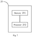
- a chip 20 includes a memory 201 and a processor 202; where the memory 201 may store computer program instructions, and the processor 202 may invoke the computer program instructions stored in the memory 201, such that the chip 20 may execute the method for updating a capacitor reference provided in the first aspect or any one of the possible implementations in the first aspect described above.
- the memory 201 may be a volatile memory (VM) such as a random access memory (RAM), or a non-volatile memory (NVM) such as a hard disk drive (HDD) or a solid state drive (SSD), or a circuit or any other apparatus capable of realizing storage functions.
- VM volatile memory
- RAM random access memory
- NVM non-volatile memory
- HDD hard disk drive
- SSD solid state drive
- the memory 201 is, and is not limited to, any other medium that may store or carry desired program codes in the form of instructions or data structures and can be accessed by a computer.
- the processor 202 may be, and is not limited to, a general purpose processor (such as a microprocessor), a digital signal processor, an application specific integrated circuit, a transistor logic device, a field programmable gate array, or other programmable logic devices, and may implement or execute the methods, steps, and logic block diagrams provided in the embodiments of the present disclosure.
- the methods and steps provided in the embodiments of the present disclosure may be directly embodied as being executed and completed by a hardware processor, or being executed and completed by a combination of hardware and software modules in the processor.
- the chip 20 may also be referred to as a system chip, a system-on-chip, and so on.
- an embodiment of the present disclosure provides a capacitance detection apparatus, including the chip as provided in the above second aspect.
- the capacitance detection apparatus may execute the method for updating a capacitance reference provided in the first aspect or any one of the possible implementations in the first aspect described above.
- an embodiment of the present disclosure provides a computer readable storage medium that may store a computer program, where the computer program may cause a computer to execute the method for updating a capacitance reference provided in the first aspect or any one of the possible implementations in the first aspect described above.
- the computer readable storage medium may be any available medium accessible to the computer, or may be a data storage device, such as a server or a data center, integrated with one or more available mediums.
- the available medium may be, and is not limited to, a magnetic medium (such as a hard disk drive, a floppy disk, or a magnetic tape), a semiconductor medium (such as a solid state drive), or an optical medium (such as a digital video disk (DVD).
- the methods provided in the embodiments of the present application may be implemented completely or partially by software, hardware, firmware, or any combination thereof, and when implemented by software, may be implemented completely or partially in the form of a computer program product, where the computer program product includes one or more computer instructions.
- the computer instructions When the computer instructions are loaded and executed on a computer, the processes or functions described according to the embodiments of the present disclosure may be generated completely or partially; the computer may be a general purpose computer, a special purpose computer, a computer network, a network device, a user device, or other programmable apparatuses; and the computer instructions may be stored in a computer readable storage medium, or transmitted from one computer readable storage medium to another computer readable storage medium, for example, the computer instructions may be transmitted from a computer, server, website, or data center to another computer, server, website, or data center by wired transmission (such as light, coaxial cable, or digital subscriber line (DSL)) or wireless transmission (such as microwave, millimeter wave, or infrared).
- wired transmission
Landscapes
- Engineering & Computer Science (AREA)
- Power Engineering (AREA)
- Physics & Mathematics (AREA)
- General Physics & Mathematics (AREA)
- Electronic Switches (AREA)
- Measurement Of Length, Angles, Or The Like Using Electric Or Magnetic Means (AREA)
Abstract
Description
- Embodiments of the present disclosure relate to the technical field of capacitance detection, and in particular to a method for updating a capacitance reference, a chip, and a capacitance detection apparatus.
- A capacitance detection apparatus can identify whether a human body or other conductors are approaching based on a capacitance value variation.
Fig. 1 shows a schematic structural diagram of a typical capacitance detection apparatus. The capacitance detection apparatus includes: asensor 101, an amplifier (AMP) 102, and an analog to digital converter (ADC) 103. When a human body or other conductors are approaching, a capacitance value of a capacitor Cx of thesensor 101 to the system ground GND will vary. Thesensor 101 may output a detected capacitance signal to theamplifier 102, to input an amplified capacitance signal to the analog todigital converter 103, thereby obtaining a raw capacitance signal RawData. A difference value between the raw capacitance signal RawData and a reference signal Ref may be computed to obtain a capacitance variation signal Diff; and a signal value of the capacitance variation signal Diff may be compared with a preset threshold to identify whether a human body or other conductors are approaching or moving away from the capacitance detection apparatus. The reference signal Ref is a signal outputted from the capacitance detection apparatus when there is no additional input from a human body or other conductors. -
Fig. 2 shows a schematic fluctuation diagram of a raw capacitance signal RawData outputted from the above typical capacitance detection apparatus; as can be seen therefrom, at a moment t1, a signal value of the raw capacitance signal RawData is equal to a signal value of a reference signal Ref, indicating that no human body or other conductors are approaching the capacitance detection apparatus; at a moment t2, a signal value of the raw capacitance signal RawData reaches a proximity threshold ONth, indicating that a human body or other conductors have approached the capacitance detection apparatus; and at a moment t3, the signal value of the raw capacitance signal RawData decreases to an off threshold OFFth, indicating that the human body or other conductors are moving away from the capacitance detection apparatus. - However, in a practical application, factors such as an ambient temperature or noise interference will cause reference drift. Therefore, if the signal value of the reference signal Ref is not updated in real time, a signal value of a capacitance variation signal Diff will tend to deviate from a capacitance variation with respect to an actual operation, thus further resulting in misrecognition or missed recognition of an event. The event includes: a human body or other conductors approach the capacitance detection apparatus, or a human body or other conductors move away from the capacitance detection apparatus.
- In the prior art, a common reference updating method is first-order hysteresis filtering, which may be described by an equation below:

- Ref(n) is a current n-th frame of reference value of the reference signal Ref, Ref(n-1) is an (n-1)-th frame of reference value of the reference signal Ref, RawData(n) is the current n-th frame of raw capacitance data of the raw capacitance signal RawData, and Coefx is a filter coefficient. The size of the filter coefficient Coefx can affect smoothness and delayed response of the Ref(n), and the size of the filter coefficient Coefx is adjusted such that the higher the smoothness is, the greater the delayed response is; and the smaller the delayed response is, the lower the smoothness is.
- The reference updating method weighs current sampled RawData(n) and last outputted Ref(n-1), to update partial data of the raw capacitance signal RawData to a new reference signal Ref. However, this method will partially update both valid data and noise in the raw capacitance signal RawData to the reference signal Ref, resulting in noise jitter in the computed capacitance variation signal Diff. If it is intended to reduce jitter of the reference signal Ref, greater delayed response will be caused. Therefore, the above reference updating method is difficult to be adapted to an application scenario that is more sensitive to noise interference and delayed response.
- Embodiments of the present disclosure provide a method for updating a capacitance reference, a chip, and a capacitance detection apparatus, for effectively updating the capacitance reference value in real time, and reducing the impacts of noise jitter and delayed response on the capacitance detection performance.
- In a first aspect, an embodiment of the present disclosure provides a method for updating a capacitance reference. The method is applied to a capacitance detection apparatus, and includes:
- determining, based on an n-th frame of raw capacitance data RawData(n) and an (n-M)-th frame of raw capacitance data RawData(n-M) outputted from the capacitance detection apparatus, a feature value Feature(n) corresponding to the n-th frame of raw capacitance data; where the feature value Feature(n) corresponding to the n-th frame of raw capacitance data is used for indicating different stages in a process of a conductor approaching or moving away from the capacitance detection apparatus;
- computing a difference value between the n-th frame of raw capacitance data RawData(n) and a reference value Ref(n-1) corresponding to an (n-1)-th frame of raw capacitance data outputted from the capacitance detection apparatus, to obtain a capacitance variation Diff(n); and
- determining, when the feature value Feature(n) corresponding to the n-th frame of raw capacitance data is less than a first threshold Thr1 , and the capacitance variation Diff(n) is less than a proximity threshold Thron , the n-th frame of raw capacitance data RawData(n) or the (n-1)-th frame of raw capacitance data RawData(n-1) as a reference value Ref(n) corresponding to the n-th frame of raw capacitance data; where the proximity threshold Thron is used for determining whether the conductor has approached the capacitance detection apparatus; and the first threshold Thr1 is used for determining whether there is an additional input from the conductor on the capacitance detection apparatus;
- where n is a positive integer greater than 2, M is a positive integer greater than or equal to 1, and M <n.
- The feature value Feature(n) corresponding to the n-th frame of raw capacitance data is set based on the n-th frame of raw capacitance data RawData(n) and the (n-M)-th frame of raw capacitance data RawData(n-M); and the size of the feature value Feature(n) is compared with the size of the first threshold, thereby determining whether there is an additional input from a human body or other conductors on the capacitance detection apparatus. When the feature value Feature(n) corresponding to the n-th frame of raw capacitance data of is less than the first threshold Thr1 , and the capacitance variation Diff(n) is less than the proximity threshold Thron , it means that there is no additional input from a human body or other conductors on the capacitance detection apparatus, i.e., the capacitance detection apparatus is in an empty state. In this stage, the reference value Ref(n) corresponding to the n-th frame of raw capacitance data is set to be equal to the n-th frame of raw capacitance data RawData(n) or the (n-1)-th frame of raw capacitance data RawData(n-1), thereby offsetting partial noise in a capacitance variation signal Diff, enabling the capacitance variation signal Diff to track the fluctuations of the raw capacitance signal RawData in real time, and reducing the impacts of noise jitter and delayed response on the capacitance detection performance.
- Alternatively, when the feature value Feature(n) corresponding to the n-th frame of raw capacitance data is greater than or equal to the first threshold Thr1 , and the capacitance variation Diff(n) is less than the proximity threshold Thron , the reference value Ref(n) corresponding to the n-th frame of raw capacitance data is determined based on the reference value Ref(n-1) corresponding to the (n-1)-th frame of raw capacitance data.
- Alternatively, when the feature value Feature(n) corresponding to the n-th frame of raw capacitance data is greater than or equal to a second threshold Thr2 , and is less than or equal to the first threshold Thr1 , and the capacitance variation Diff(n) is greater than or equal to the proximity threshold Thron , the reference value Ref(n) corresponding to the n-th frame of raw capacitance data is determined based on the feature value Feature(n) corresponding to the n-th frame of raw capacitance data, a feature value Feature(n-1) corresponding to the (n-1)-th frame of raw capacitance data, the reference value Ref(n-1) corresponding to the (n-1)-th frame of raw capacitance data, and a reference value Ref(n-2) corresponding to an (n-2)-th frame of raw capacitance data outputted from the capacitance detection apparatus; where the second threshold Thr2 is used for determining whether the conductor is gradually disconnected from contact with the capacitance detection apparatus;
where the second threshold Thr2 is less than the first threshold Thr1. - Alternatively, when the feature value Feature(n) corresponding to the n-th frame of raw capacitance data is less than the second threshold Thr2 or greater than the first threshold Thr1 , and the capacitance variation Diff(n) is greater than or equal to the proximity threshold Thron , the reference value Ref(n) corresponding to the n-th frame of raw capacitance data is determined based on the reference value Ref(n-1) corresponding to the (n-1)-th frame of raw capacitance data.
- Alternatively, the determining, based on the n-th frame of raw capacitance data RawData(n) and the (n-M)-th frame of raw capacitance data RawData(n-M) outputted from the capacitance detection apparatus, the feature value Feature(n) corresponding to the n-th frame of raw capacitance data further includes:
determining a difference value between the n-th frame of raw capacitance data RawData(n) and the (n-M)-th frame of raw capacitance data RawData(n-M) as the feature value Feature(n) corresponding to the n-th frame of raw capacitance data. - Alternatively, the determining, when the feature value Feature(n) corresponding to the n-th frame of raw capacitance data is less than the first threshold Thr1 , and the capacitance variation Diff(n) is less than the proximity threshold Thron , the n-th frame of raw capacitance data RawData(n) or the (n-1)-th frame of raw capacitance data RawData(n-1) as the reference value Ref(n) corresponding to the n-th frame of raw capacitance data further includes:
determining a minimum value of the n-th frame of raw capacitance data RawData(n) and the (n-1)-th frame of raw capacitance data RawData(n-1) as the reference value Ref(n) corresponding to the n-th frame of raw capacitance data. - Alternatively, the determining, when the feature value Feature(n) corresponding to the n-th frame of raw capacitance data is greater than or equal to the first threshold Thr1 , and the capacitance variation Diff(n) is less than the proximity threshold Thron , the reference value Ref(n) corresponding to the n-th frame of raw capacitance data based on the reference value Ref(n-1) corresponding to the (n-1)-th frame of raw capacitance data further includes:
- determining, when the feature value Feature(n) corresponding to the n-th frame of raw capacitance data is greater than or equal to the first threshold Thr1 , and is less than a third threshold Thr3 , and the capacitance variation Diff(n) is less than the proximity threshold Thron , a sum of the reference value Ref(n-1) corresponding to the (n-1)-th frame of raw capacitance data and a first correction value Corr1 as the reference value Ref(n) corresponding to the n-th frame of raw capacitance data;
- determining, when the feature value Feature(n) corresponding to the n-th frame of raw capacitance data is greater than or equal to the third threshold Thr3 , and the capacitance variation Diff(n) is less than the proximity threshold Thron , a sum of the reference value Ref(n-1) corresponding to the (n-1)-th frame of raw capacitance data and a second correction value Corr2 as the reference value Ref(n) corresponding to the n-th frame of raw capacitance data; where the third threshold Thr3 is used for determining an extent to which the conductor is approaching the capacitance detection apparatus; and
- the first correction value Corr1 and the second correction value Corr2 are used for characterizing an offset of a reference value caused by an environmental factor in a corresponding stage, respectively;
- where the third threshold Thr3 is greater than the first threshold Thr1.
- Alternatively, the determining, when the feature value Feature(n) corresponding to the n-th frame of raw capacitance data is greater than or equal to the second threshold Thr2 , and is less than or equal to the first threshold Thr1 , and the capacitance variation Diff(n) is greater than or equal to the proximity threshold Thron , the reference value Ref(n) corresponding to the n-th frame of raw capacitance data based on the feature value Feature(n) corresponding to the n-th frame of raw capacitance data, the feature value Feature(n-1) corresponding to the (n-1)-th frame of raw capacitance data, the reference value Ref(n-1) corresponding to the (n-1)-th frame of raw capacitance data, and the reference value Ref(n-2) corresponding to the (n-2)-th frame of raw capacitance data outputted from the capacitance detection apparatus further includes:
- computing a difference value between the feature value Feature(n) corresponding to the n-th frame of raw capacitance data and the feature value Feature(n-1) corresponding to the (n-1)-th frame of raw capacitance data, to obtain a first variation Diff Feature(n);
- computing a difference value between the reference value Ref(n-1) corresponding to the (n-1)-th frame of raw capacitance data and the reference value Ref(n-2) corresponding to the (n-2)-th frame of raw capacitance data, to obtain a second variation Diff-Ref(n-1); and
- enabling the reference value Ref(n) corresponding to the n-th frame of raw capacitance data to satisfy an equation below:
- A value of the second variation Diff_Ref(n-1) is not zero.
- Alternatively, the determining, when the feature value Feature(n) corresponding to the n-th frame of raw capacitance data is less than the second threshold Thr2 or greater than the first threshold Thr1 , and the capacitance variation Diff(n) is greater than or equal to the proximity threshold Thron , the reference value Ref(n) corresponding to the n-th frame of raw capacitance data based on the reference value Ref(n-1) corresponding to the (n-1)-th frame of raw capacitance data further includes:
- determining, when the feature value Feature(n) corresponding to the n-th frame of raw capacitance data is greater than the first threshold Thr1 , and the capacitance variation Diff(n) is greater than or equal to the proximity threshold Thron , the sum of the reference value Ref(n-1) corresponding to the (n-1)-th frame of raw capacitance data and the second correction value Corr2 as the reference value Ref(n) corresponding to the n-th frame of raw capacitance data; and
- determining, when the feature value Feature(n) corresponding to the n-th frame of raw capacitance data is less than the second threshold Thr2 , and the capacitance variation Diff(n) is greater than or equal to the proximity threshold Thron , a sum of the reference value Ref(n-1) corresponding to the (n-1)-th frame of raw capacitance data and a third correction value Corr3 as the reference value Ref(n) corresponding to the n-th frame of raw capacitance data;
- where the third correction value Corr3 is used for characterizing an offset of a reference value caused by an environmental factor in a corresponding stage.
- In a second aspect, an embodiment of the present disclosure provides a chip, including a processor and a memory, where the memory is coupled to the processor;
- the memory is configured to store computer program instructions; and
- the processor is configured to invoke the computer program instructions stored in the memory, such that the chip executes the method for updating a capacitance reference according to the first aspect or any one alternative implementation in the first aspect.
- In a third aspect, an embodiment of the present disclosure provides a capacitance detection apparatus, including the chip according to the second aspect.
- In a fourth aspect, an embodiment of the present disclosure provides a computer readable storage medium configured to store a computer program, where the computer program causes a computer to execute the method for updating a capacitance reference according to the first aspect or any one alternative implementation in the first aspect.
- It is understandable that the chip according to the second aspect, the capacitance detection apparatus according to the third aspect, and the computer readable storage medium according to the fourth aspect provided above are all configured to execute the corresponding method provided above, and therefore, the beneficial effects in the corresponding methods provided above may be referred to for the beneficial effects to be achieved whereby. The description will not be repeated here.
- One or more embodiments are illustrated with reference to the pictures in the corresponding drawings, but these illustrations do not constitute a limitation on the embodiments. In addition, unless otherwise particularly stated, the figures in the accompanying drawings do not constitute a limitation of scale.
-
Fig. 1 is a schematic structural diagram of a typical capacitance detection apparatus; -
Fig. 2 is a schematic fluctuation diagram of a raw capacitance signal RawData outputted from the capacitance detection apparatus shown inFig. 1 ; -
Fig. 3 is a schematic block diagram of a method for updating a capacitance reference provided in an embodiment of the present disclosure; -
Fig. 4 is a schematic fluctuation diagram of a raw capacitance signal and a feature signal in a process of a conductor approaching and moving away provided in an embodiment of the present disclosure; -
Fig. 5 is a schematic diagram of updating a reference signal in a process of a conductor approaching and moving away provided in an embodiment of the present disclosure; -
Fig. 6 is a schematic fluctuation diagram of a capacitance variation signal in a process of a conductor approaching and moving away provided in an embodiment of the present disclosure; and -
Fig. 7 is a schematic structural diagram of a chip provided in an embodiment of the present disclosure. - The technical solutions in embodiments of the present disclosure will be clearly and completely described below with reference to the accompanying drawings. Apparently, the embodiments described below are a part, instead of all, of the embodiments of the present disclosure.
- The terms used in the present disclosure are intended merely to describe particular embodiments, and are not intended to limit the present disclosure. The singular forms of "a" and "the" used in the present disclosure and the appended claims are also intended to include plural forms, unless the context clearly indicates other meanings.
- It should also be understood that unless a specified order is clearly stated in the context of the present disclosure, the processing steps described herein may be performed differently from the specified order. That is, each step may be performed in the specified order, or each step may be performed substantially simultaneously, each step may be performed in a reverse order, or each step may be performed in a different order.
- In addition, the terms such as "first" and "second" are only used for distinguishing between similar objects, and cannot be understood as indicating or implying relative importance or implicitly indicating the number of indicated technical features. Thus, features defined with "first," "second," or the like may explicitly or implicitly include one or more of the features.
- As shown in
Fig. 3 , a schematic block diagram of a method for updating a capacitance reference provided in an embodiment of the present disclosure is shown. The method may be applied to a capacitance detection apparatus, and specifically includes the following steps:
Step S101: determining, based on an n-th frame of raw capacitance data RawData(n) and an (n-M)-th frame of raw capacitance data RawData(n-M) outputted from the capacitance detection apparatus, a feature value Feature(n) corresponding to the n-th frame of raw capacitance data. - The feature value Feature(n) corresponding to the n-th frame of raw capacitance data may indicate a different stage in a process of a conductor (a human body or other conductors) approaching or moving away from the capacitance detection apparatus.
- Step S102: computing a difference value between the n-th frame of raw capacitance data RawData(n) and a reference value Ref(n-1) corresponding to an (n-1)-th frame of raw capacitance data outputted from the capacitance detection apparatus, to obtain a capacitance variation Diff(n).
- By setting the capacitance variation Diff(n)=RawData(n)-Ref(n-1), a capacitance variation corresponding to the n-th frame of raw capacitance data may be predicted based on the capacitance variation Diff(n), thereby determining a moving state of the conductor. Specifically, the moving state may include: having approached the capacitance detection appearance (approached state) and not approaching the capacitance detection apparatus (non-approaching state). The capacitance variation corresponding to the n-th frame of raw capacitance data is the difference value between the n-th frame of raw capacitance data RawData(n) and the corresponding reference value Ref(n) thereof, i.e., RawData(n)-Ref(n), which may be used for indicating a current capacitance variation caused by the human body or other conductors.
- Step S103a: determining, when the feature value Feature(n) corresponding to the n-th frame of raw capacitance data is less than a first threshold Thr1 , and the capacitance variation Diff(n) is less than a proximity threshold Thron , the n-th frame of raw capacitance data RawData(n) or the (n-1)-th frame of raw capacitance data RawData(n-1) as a reference value Ref(n) corresponding to the n-th frame of raw capacitance data. The proximity threshold Thron may be used for determining whether the conductor has approached the capacitance detection apparatus; and the first threshold Thr1 may be used for determining whether there is an additional input from the conductor on the capacitance detection apparatus.
- The capacitance variation Diff(n) may be compared with the proximity threshold Thron , to determine whether the conductor has approached the capacitance detection apparatus, i.e., determine the moving state of the conductor. Specifically, if the capacitance variation Diff(n) reaches the proximity threshold Thron , i.e., is greater than or equal to the proximity threshold Thron , it may be determined that the conductor is in the approached state; and if the capacitance variation Diff(n) does not reach the proximity threshold Thron , i.e., is less than the proximity threshold Thron , it may be determined that the conductor is in a non-approaching state. In addition, the size of the proximity threshold Thron may be generated by machine learning based on training data. The training data may include, but is not limited to, a corresponding capacitance variation Diff(n) when different types of conductors come in contact with the capacitance detection apparatus to different extents and a corresponding capacitance variation Diff(n) when there are different distances between different types of conductors and the capacitance detection apparatus. In addition, the size of the proximity threshold Thron may also be adjusted accordingly based on subsequent actual applications of a user, thereby more accurately distinguishing whether the human body or other conductors have approached the capacitance detection apparatus, and better adapting to different application scenarios.
- Step S103b: determining, when the feature value Feature(n) corresponding to the n-th frame of raw capacitance data is greater than or equal to the first threshold Thr1 , and the capacitance variation Diff(n) is less than the proximity threshold Thron , the reference value Ref(n) corresponding to the n-th frame of raw capacitance data based on the reference value Ref(n-1) corresponding to the (n-1)-th frame of raw capacitance data.
- Step S103c: determining, when the feature value Feature(n) corresponding to the n-th frame of raw capacitance data is greater than or equal to a second threshold Thr2 , and is less than or equal to the first threshold Thr1 , and the capacitance variation Diff(n) is greater than or equal to the proximity threshold Thron , the reference value Ref(n) corresponding to the n-th frame of raw capacitance data based on the feature value Feature(n) corresponding to the n-th frame of raw capacitance data, a feature value Feature(n-1) corresponding to the (n-1)-th frame of raw capacitance data, the reference value Ref(n-1) corresponding to the (n-1)-th frame of raw capacitance data, and a reference value Ref(n-2) corresponding to an (n-2)-th frame of raw capacitance data outputted from the capacitance detection apparatus.
- The second threshold Thr2 is less than the first threshold Thr1. The second threshold Thr2 may be used for determining whether the conductor is gradually disconnected from contact with the capacitance detection apparatus, and specifically may be used for further determining whether a moving trend of the conductor in the approached state is to maintain stable contact with the capacitance detection apparatus or to start to move away from the capacitance detection apparatus.
- Step S103d: determining, when the feature value Feature(n) corresponding to the n-th frame of raw capacitance data is less than the second threshold Thr2 or greater than the first threshold Thr1 , and the capacitance variation Diff(n) is greater than or equal to the proximity threshold Thron , the reference value Ref(n) corresponding to the n-th frame of raw capacitance data based on the reference value Ref(n-1) corresponding to the (n-1)-th frame of raw capacitance data.
- In the above, n is a positive integer greater than 2, M is a positive integer greater than or equal to 1, and M <n. When n is greater than 1 or 2, a value of Ref (1) or Ref (2) may be set to be equal to a signal value of a raw capacitance signal outputted from the capacitance detection apparatus when there is no additional input from a human body or other conductors.
- Specifically, setting of the first threshold Thr1 may also be generated by machine learning based on training data. The training data may include, but is not limited to: a capacitance variation when there is no additional input from a human body or other conductors on the capacitance detection apparatus, a capacitance variation when a human body or other conductors start to approach the capacitance detection apparatus, and a capacitance variation when a human body or other conductors start to move away from the capacitance detection apparatus. In addition, the second threshold Thr2 may be set as a negative value, and its absolute value may be from 2 to 3 times as much as the first threshold Thr1.
- The feature value Feature(n) is set based on the n-th frame of raw capacitance data RawData(n) and the (n-M)-th frame of raw capacitance data RawData(n-M), the size of the feature value Feature(n) is compared with the size of a preset threshold, a process of a human body or other conductors approaching or moving away from the capacitance detection apparatus may be classified into different stages, and a corresponding capacitance reference updating approach may be set based on different moving states (approached/non-approaching) and moving trends (approaching, maintaining contact, moving away) of a conductor in each stage, thereby effectively updating the reference value in real time.
- Specifically, Feature(n)<Thr1 and Diff(n)<Thron may indicate that there is no additional input caused by a conductor on the capacitance detection apparatus, including: no conductor starts to approach the capacitance detection apparatus, and a conductor has moved away from the capacitance detection apparatus; and the raw capacitance data RawData(n) in this stage only indicates a capacitance variation caused by an environmental noise, such that this stage may be referred to as a noise stage.
- Feature(n)≥Thr1 and Diff(n)<Thron may indicate that a conductor is slowly/rapidly approaching the capacitance detection apparatus, but the conductor is still in a non-approaching state, such that this stage may be referred to as a pre-approaching stage.
- Thr2 ≤Feature(n)≤Thr1 and Diff(n)≥Thron may indicate that a conductor maintains stable contact with the capacitance detection apparatus, and has reached a most approaching state; and Feature(n)>Thr1 or Feature(n) <Thr2 and Diff(n) ≥Thron means that the conductor is in the approached state and is further approaching the capacitance detection apparatus, or is gradually disconnected from contact with the capacitance detection apparatus, i.e., starts to leave from the capacitance detection apparatus. The two stages may be referred to as an approaching stage.
- As a possible implementation, the determining, based on the n-th frame of raw capacitance data RawData(n) and the (n-M)-th frame of raw capacitance data RawData(n-M) outputted from the capacitance detection apparatus, the feature value Feature(n) corresponding to the n-th frame of raw capacitance data further includes: determining a difference value between the n-th frame of raw capacitance data RawData(n) and the (n-M)-th frame of raw capacitance data RawData(n-M) as the feature value Feature(n) corresponding to the n-th frame of raw capacitance data.
- Therefore, Feature(n)=RawData(n)-RawData(n-M) may be set. A value of M may be set based on an actual application scenario and to-be-achieved application objective, and may be at least 1. Further, the smaller the value of M is, the better the timeliness of the capacitor reference update is, but the higher the computing workload is.
- As a possible implementation, the determining, when the feature value Feature(n) corresponding to the n-th frame of raw capacitance data is less than the first threshold Thr1 , and the capacitance variation Diff(n) is less than the proximity threshold Thron , the n-th frame of raw capacitance data RawData(n) or the (n-1)-th frame of raw capacitance data RawData(n-1) as the reference value Ref(n) corresponding to the n-th frame of raw capacitance data further includes: determining a minimum value of the n-th frame of raw capacitance data RawData(n) and the (n-1)-th frame of raw capacitance data RawData(n-1) as the reference value Ref(n) corresponding to the n-th frame of raw capacitance data.
- Therefore, Ref(n)=min{RawData(n), RawData(n-1)} may be set in the noise stage. This reference updating approach may enable a noise in a capacitance variation signal Diff in this stage to merely have a one-way variation, thereby effectively reducing a noise of a reverse variation in the capacitance variation signal Diff, can reduce a noise variance in the capacitance variation signal Diff in this stage by half compared with first-order hysteresis filtering commonly used in the prior art, will not consume a valid signal component in the capacitance variation signal Diff, and in addition, may also enable the reference signal Ref to track the fluctuations of the raw capacitance signal RawData in real time, thereby reducing the impacts of noise jitter and delayed response on the capacitance detection performance.
- As a possible implementation, the determining, when the feature value Feature(n) corresponding to the n-th frame of raw capacitance data is greater than or equal to the first threshold Thr1 , and the capacitance variation Diff(n) is less than the proximity threshold Thron , the reference value Ref(n) corresponding to the n-th frame of raw capacitance data based on the reference value Ref(n-1) corresponding to the (n-1)-th frame of raw capacitance data further includes:
When the feature value Feature(n) corresponding to the n-th frame of raw capacitance data is greater than or equal to the first threshold Thr1 , and is less than a third threshold Thr3 , and the capacitance variation Diff(n) is less than the proximity threshold Thron , a sum of the reference value Ref(n-1) corresponding to the (n-1)-th frame of raw capacitance data and a first correction value Corr1 is determined as the reference value Ref(n) corresponding to the n-th frame of raw capacitance data; and when the feature value Feature(n) corresponding to the n-th frame of raw capacitance data is greater than or equal to the third threshold Thr3 , and the capacitance variation Diff(n) is less than the proximity threshold Thron , a sum of the reference value Ref(n-1) corresponding to the (n-1)-th frame of raw capacitance data and a second correction value Corr2 is determined as the reference value Ref(n) corresponding to the n-th frame of raw capacitance data. The third threshold Thr3 may be used for determining an extent to which the conductor is approaching the capacitance detection apparatus, and the third threshold Thr3 is greater than the first threshold Thr1; and the first correction value Corr1 and the second correction value Corr2 may be used for characterizing an offset of a reference value caused by an environmental factor in a corresponding stage, respectively. - Therefore, in the pre-approaching stage, this reference updating approach can reduce the reference drift noise caused by an environmental factor such as temperature, improve the signal-to-noise ratio of the capacitance variation signal Diff, and update the reference signal Ref in real time, thereby reducing the impacts of noise jitter and delayed response on the capacitance detection performance.
- Therefore, the pre-approaching stage may be further divided into two sub-stages, and a human body or other conductors approach the capacitance detection apparatus to different extents in the two sub-stages. Specifically, when Thr1 ≤Feature(n)<Thr3 , and Diff(n)<Thron , Ref(n)=Ref(n-1)+Corr1 is set, and this stage may be referred to as a first pre-approaching sub-stage; and when Feature(n)≥Thr3 and Diff(n)<Thron , Ref(n)=Ref(n-1)+Corr2 is set, and this stage may be referred to as a second pre-approaching sub-stage. The approaching extent in the second pre-approaching stage is higher than that in the first pre-approaching stage. Specifically, the first correction value Corr1 may be set to be about 20% of the proximity threshold Thron , and the second correction value Corr2 may be set to be equal to the first correction value Corr1 or slightly smaller than the first correction value Corr1. The third threshold Thr3 may be set as an opposite number of the second threshold Thr2 , i.e., 2 to 3 times as much as the first threshold Thr1.
- As a possible implementation, the determining, when the feature value Feature(n) corresponding to the n-th frame of raw capacitance data is greater than or equal to the second threshold Thr2 , and is less than or equal to the first threshold Thr1 , and the capacitance variation Diff(n) is greater than or equal to the proximity threshold Thron , the reference value Ref(n) corresponding to the n-th frame of raw capacitance data based on the feature value Feature(n) corresponding to the n-th frame of raw capacitance data, the feature value Feature(n-1) corresponding to the (n-1)-th frame of raw capacitance data, the reference value Ref(n-1) corresponding to the (n-1)-th frame of raw capacitance data, and the reference value Ref(n-2) corresponding to the (n-2)-th frame of raw capacitance data outputted from the capacitance detection apparatus further includes:
- computing a difference value between the feature value Feature(n) corresponding to the n-th frame of raw capacitance data and the feature value Feature(n-1) corresponding to the (n-1)-th frame of raw capacitance data, to obtain a first variation Diff_Feature(n); computing a difference value between the reference value Ref(n-1) corresponding to the (n-1)-th frame of raw capacitance data and the reference value Ref(n-2) corresponding to the (n-2)-th frame of raw capacitance data outputted from the capacitance detection apparatus, to obtain a second variation Diff-Ref(n-1); and enabling the reference value Ref(n) corresponding to the n-th frame of raw capacitance data to satisfy an equation below:

- The second variation Diff_Ref(n-1)≠0. If in this stage, Ref(n-1) is equal to Ref(n-2), the second variation Diff_Ref(n-1) may be set as a non-zero constant value, for example, may be set to be equal to a value of a non-zero second variation Diff_Ref(n-1) in a previous frame.
- In this stage, the conductor steadily maintains contact with the capacitance detection apparatus, and is in the most approaching state. The conductor generally shakes to a certain extent or has a temperature difference from a sensor in the capacitance detection apparatus, which tends to cause abnormal jitter variation of the raw capacitance signal RawData, further makes the capacitance variation signal Diff have an obvious noise component, and affects the accuracy of the capacitance detection result, while the updating the capacitance reference value in real time by the above approach can extract the jitter variation in the raw capacitance signal RawData in a process of the conductor maintaining continuous and stable contact with the capacitance detection apparatus, and superimpose the jitter variation to the reference signal Ref, thereby reducing low-frequency noise in the capacitance variation signal Diff, and effectively reducing the probability of misrecognition or missed recognition of an event.
- As a possible implementation, the determining, when the feature value Feature(n) corresponding to the n-th frame of raw capacitance data is less than the second threshold Thr2 or greater than the first threshold Thr1 , and the capacitance variation Diff(n) is greater than or equal to the proximity threshold Thron , the reference value Ref(n) corresponding to the n-th frame of raw capacitance data based on the reference value Ref(n-1) corresponding to the (n-1)-th frame of raw capacitance data further includes:
determining, when the feature value Feature(n) corresponding to the n-th frame of raw capacitance data is greater than the first threshold Thr1 , and the capacitance variation Diff(n) is greater than or equal to the proximity threshold Thron , the sum of the reference value Ref(n-1) corresponding to the (n-1)-th frame of raw capacitance data and the second correction value Corr2 as the reference value Ref(n) corresponding to the n-th frame of raw capacitance data; and determining, when the feature value Feature(n) corresponding to the n-th frame of raw capacitance data is less than the second threshold Thr2 , and the capacitance variation Diff(n) is greater than or equal to the proximity threshold Thron , a sum of the reference value Ref(n-1) corresponding to the (n-1)-th frame of raw capacitance data and a third correction value Corr3 as the reference value Ref(n) corresponding to the n-th frame of raw capacitance data. - The third correction value Corr3 may be used for characterizing an offset of a reference value caused by an environmental factor in a corresponding stage. Specifically, the third correction value Corr3 may be set based on an actual application scenario, and may be equal to the first correction value Corr1 and the second correction value Corr2 , or slightly smaller than the first correction value Corr1.
- Therefore, this stage may be further divided into two sub-stages. Feature(n)>Thr1 and Diff(n) ≥Thron means that the conductor is in an approached state and is further approaching the capacitance detection apparatus. Ref(n)=Ref(n-1)+Corr2 is set to ensure that the signal value of the reference signal Ref in this stage is continuous with the signal value in the last stage (the second pre-approaching sub-stage). Feature(n)<Thr2 and Diff(n) ≥Thron means that the conductor is in the approached state, but is gradually disconnected from contact with the capacitance detection apparatus, i.e., starts to leave from the capacitance detection apparatus. Ref(n)=Ref (n-1)+Corr3 is set to ensure that the reference signal Ref can be promptly updated in real time following the raw capacitance signal RawData.
- In this stage, the above reference updating approach can reduce the reference drift noise caused by an environmental factor such as temperature, improve the signal-to-noise ratio of the capacitance variation signal Diff, and enable the reference signal Ref to promptly track the variation of the raw capacitance signal RawData in real time, thereby reducing the impacts of noise jitter and delayed response on the capacitance detection performance.
- As shown in
Fig. 4 , a schematic fluctuation diagram of a raw capacitance signal and a feature signal in a process of a conductor approaching and moving away provided in an embodiment of the present disclosure is shown. It can be seen that by comparing the Feature(n) with the first threshold Thr1 , the second threshold Thr2 , and the third threshold Thr3 , the process of the conductor approaching and moving away from a capacitance detection apparatus may be divided into different stages, including a noise stage (T1 and T4), a pre-approaching stage (T2), and an approaching stage (T3), where, in the T1 period of the noise stage, there is no additional input from the conductor on the capacitance detection apparatus, and in the T4 period of the noise stage, the conductor has moved away from the capacitor detection apparatus; and the pre-approaching stage may be further divided into two sub-stages based on different approaching extents, and the approaching stage may be further divided into three sub-stages based on different moving trends. In addition, it can be seen that a feature signal Feature corresponding to M=10 has a smaller delayed response than a feature signal Feature corresponding to M=20. - As shown in
Fig. 5 , a schematic diagram of updating a reference signal in a process of a conductor approaching and moving away provided in an embodiment of the present disclosure is shown; where the method for updating a capacitance reference provided in the above embodiments is used respectively in each stage of the conductor approaching and moving away from a capacitance detection apparatus. It can be seen that in T1 period (noise stage), there is no additional input from a human body or other conductors on the capacitance detection apparatus, and a reference signal Ref can be updated in real time to track the variation of a raw capacitance signal RawData; in T2 period (pre-approaching stage), a human body or other conductors are approaching the capacitance detection apparatus, but are still in a non-approaching state, and the reference signal Ref can track rise and variation of the raw capacitance signal RawData in time and update the raw capacitance signal in real time; in T3 period (approaching stage), when a human body or other conductors are in an approached state and maintain stable contact with the capacitance detection apparatus, the reference signal Ref can also track the jitter variation of the raw capacitance signal RawData in real time, effectively reduce a low-frequency noise component in the capacitance variation signal Diff, and improve the signal-to-noise ratio of the capacitance variation signal Diff, thereby improving the accuracy of the capacitance detection result; and when the human body or other conductors are in an approached state and are further approaching the capacitance detection apparatus or are gradually disconnected from contact with the capacitance detection apparatus, the reference signal Ref can update the raw capacitance signal RawData in real time based on the variation; and in T4 period (noise stage), the human body or other conductors have moved away from the capacitance detection apparatus, the reference signal Ref can be quickly updated and quickly restored to a regular reference level, thereby reducing the impacts of delayed response on the sensitivity and accuracy of subsequent capacitance detection. - As shown in
Fig. 6 , a schematic fluctuation diagram of a capacitance variation signal in a process of a conductor approaching and moving away provided in an embodiment of the present disclosure is shown, where the method for updating a capacitance reference provided in the above embodiments is used respectively in each stage of the conductor rapidly/slowly approaching and moving away from a capacitance detection apparatus. It can be seen that in the process of a human body or other conductors are rapidly/slowly approaching and moving away from the capacitance detection apparatus, the capacitance variation signal can quickly reach a target level, and can accurately reflect whether the human body or other conductors are approaching the capacitance detection apparatus in real time, thereby improving the sensitivity and accuracy of capacitance detection. - In a practical application, it is often necessary to accurately recognize the process of a human body or other conductors slowly approaching and rapidly moving away in real time. Therefore, the method for updating a capacitance reference provided in the embodiments of the present disclosure can be well adapted to this application scenario.
- It should be noted that in order to adapt to sizes of different thresholds, a proportional coefficient of a feature value Feature(n) corresponding to an n-th frame of raw capacitance data may be scaled accordingly. For example, Feature(n)=[RawData(n)-RawData(nM)]∗ a may be set, where a may be a constant greater than 0, such that a value of Feature(n) corresponds to the size of a preset threshold, to effectively distinguish between different stages in the process of the conductor approaching or moving away from the capacitance detection apparatus, and different reference updating methods are set for different stages to effectively update the reference value in real time, thereby reducing the impacts of noise jitter and delayed response on the capacitance detection performance, improving the accuracy of the capacitance detection result, and reducing the probability of misrecognition or missed recognition of an event.
- The method for updating a capacitance reference provided in the embodiments of the present disclosure can be adapted to various scenarios where accurate detection of capacitance is required, including wearing detection, touch detection, SAR (Specific Absorption Rate) application, and the like. For example, in an ear detection application of a Bluetooth headset (such as a TWS earbud), the method can accurately identify whether a user has worn the Bluetooth headset.
- As shown in
Fig. 7 , a schematic structural diagram of a chip provided in an embodiment of the present disclosure is shown. Achip 20 includes amemory 201 and aprocessor 202; where thememory 201 may store computer program instructions, and theprocessor 202 may invoke the computer program instructions stored in thememory 201, such that thechip 20 may execute the method for updating a capacitor reference provided in the first aspect or any one of the possible implementations in the first aspect described above. - Specifically, the
memory 201 may be a volatile memory (VM) such as a random access memory (RAM), or a non-volatile memory (NVM) such as a hard disk drive (HDD) or a solid state drive (SSD), or a circuit or any other apparatus capable of realizing storage functions. Thememory 201 is, and is not limited to, any other medium that may store or carry desired program codes in the form of instructions or data structures and can be accessed by a computer. - The
processor 202 may be, and is not limited to, a general purpose processor (such as a microprocessor), a digital signal processor, an application specific integrated circuit, a transistor logic device, a field programmable gate array, or other programmable logic devices, and may implement or execute the methods, steps, and logic block diagrams provided in the embodiments of the present disclosure. The methods and steps provided in the embodiments of the present disclosure may be directly embodied as being executed and completed by a hardware processor, or being executed and completed by a combination of hardware and software modules in the processor. - The
chip 20 may also be referred to as a system chip, a system-on-chip, and so on. - In a third aspect, an embodiment of the present disclosure provides a capacitance detection apparatus, including the chip as provided in the above second aspect.
- The capacitance detection apparatus may execute the method for updating a capacitance reference provided in the first aspect or any one of the possible implementations in the first aspect described above.
- In a fourth aspect, an embodiment of the present disclosure provides a computer readable storage medium that may store a computer program, where the computer program may cause a computer to execute the method for updating a capacitance reference provided in the first aspect or any one of the possible implementations in the first aspect described above.
- The computer readable storage medium may be any available medium accessible to the computer, or may be a data storage device, such as a server or a data center, integrated with one or more available mediums. The available medium may be, and is not limited to, a magnetic medium (such as a hard disk drive, a floppy disk, or a magnetic tape), a semiconductor medium (such as a solid state drive), or an optical medium (such as a digital video disk (DVD).
- The methods provided in the embodiments of the present application may be implemented completely or partially by software, hardware, firmware, or any combination thereof, and when implemented by software, may be implemented completely or partially in the form of a computer program product, where the computer program product includes one or more computer instructions. When the computer instructions are loaded and executed on a computer, the processes or functions described according to the embodiments of the present disclosure may be generated completely or partially; the computer may be a general purpose computer, a special purpose computer, a computer network, a network device, a user device, or other programmable apparatuses; and the computer instructions may be stored in a computer readable storage medium, or transmitted from one computer readable storage medium to another computer readable storage medium, for example, the computer instructions may be transmitted from a computer, server, website, or data center to another computer, server, website, or data center by wired transmission (such as light, coaxial cable, or digital subscriber line (DSL)) or wireless transmission (such as microwave, millimeter wave, or infrared).
- It should be understood that the specific implementations in the embodiments of the present disclosure are provided only to help those skilled in the art to better understand the embodiments of the present disclosure, rather than limiting the scope of the embodiments of the present disclosure. Those skilled in the art may make various improvements and modifications on the basis of the above embodiments, and these improvements or modifications all fall into the scope of protection of the present disclosure.

Claims (12)
- A method for updating a capacitance reference, being applied to a capacitance detection apparatus, the method comprising:determining, based on an n-th frame of raw capacitance data RawData(n) and an (n-M)-th frame of raw capacitance data RawData(n-M) outputted from the capacitance detection apparatus, a feature value Feature(n) corresponding to the n-th frame of raw capacitance data; where the feature value Feature(n) corresponding to the n-th frame of raw capacitance data is used for indicating different stages in a process of a conductor approaching or moving away from the capacitance detection apparatus;computing a difference value between the n-th frame of raw capacitance data RawData(n) and a reference value Ref(n-1) corresponding to an (n-1)-th frame of raw capacitance data outputted from the capacitance detection apparatus, to obtain a capacitance variation Diff(n); anddetermining, when the feature value Feature(n) corresponding to the n-th frame of raw capacitance data is less than a first threshold Thr1 , and the capacitance variation Diff(n) is less than a proximity threshold Thron , the n-th frame of raw capacitance data RawData(n) or the (n-1)-th frame of raw capacitance data RawData(n-1) as a reference value Ref(n) corresponding to the n-th frame of raw capacitance data; where the proximity threshold Thron is used for determining whether the conductor has approached the capacitance detection apparatus; and the first threshold Thr1 is used for determining whether there is an additional input from the conductor on the capacitance detection apparatus;wherein n is a positive integer greater than 2, M is a positive integer greater than or equal to 1, and M <n.
- The method according to claim 1, wherein the method further comprises:
determining, when the feature value Feature(n) corresponding to the n-th frame of raw capacitance data is greater than or equal to the first threshold Thr1 , and the capacitance variation Diff(n) is less than the proximity threshold Thron , the reference value Ref(n) corresponding to the n-th frame of raw capacitance data based on the reference value Ref(n-1) corresponding to the (n-1)-th frame of raw capacitance data. - The method according to claim 2, wherein the method further comprises:determining, when the feature value Feature(n) corresponding to the n-th frame of raw capacitance data is greater than or equal to a second threshold Thr2 , and is less than or equal to the first threshold Thr1 , and the capacitance variation Diff(n) is greater than or equal to the proximity threshold Thron , the reference value Ref(n) corresponding to the n-th frame of raw capacitance data based on the feature value Feature(n) corresponding to the n-th frame of raw capacitance data, a feature value Feature(n-1) corresponding to the (n-1)-th frame of raw capacitance data, the reference value Ref(n-1) corresponding to the (n-1)-th frame of raw capacitance data, and a reference value Ref(n-2) corresponding to an (n-2)-th frame of raw capacitance data outputted from the capacitance detection apparatus; wherein the second threshold Thr2 is used for determining whether the conductor is gradually disconnected from contact with the capacitance detection apparatus;wherein the second threshold Thr2 is less than the first threshold Thr1.
- The method according to claim 3, wherein the method further comprises:
determining, when the feature value Feature(n) corresponding to the n-th frame of raw capacitance data is less than the second threshold Thr2 or greater than the first threshold Thr1 , and the capacitance variation Diff(n) is greater than or equal to the proximity threshold Thron , the reference value Ref(n) corresponding to the n-th frame of raw capacitance data based on the reference value Ref(n-1) corresponding to the (n-1)-th frame of raw capacitance data. - The method according to any one of claims 1 to 4, wherein the determining, based on the n-th frame of raw capacitance data RawData(n) and the (n-M)-th frame of raw capacitance data RawData(n-M) outputted from the capacitance detection apparatus, the feature value Feature(n) corresponding to the n-th frame of raw capacitance data further comprises:
determining a difference value between the n-th frame of raw capacitance data RawData(n) and the (n-M)-th frame of raw capacitance data RawData(n-M) as the feature value Feature(n) corresponding to the n-th frame of raw capacitance data. - The method according to claim 5, wherein the determining, when the feature value Feature(n) corresponding to the n-th frame of raw capacitance data is less than the first threshold Thr1 , and the capacitance variation Diff(n) is less than the proximity threshold Thron , the n-th frame of raw capacitance data RawData(n) or the (n-1)-th frame of raw capacitance data RawData(n-1) as the reference value Ref(n) corresponding to the n-th frame of raw capacitance data further comprises:
determining a minimum value of the n-th frame of raw capacitance data RawData(n) and the (n-1)-th frame of raw capacitance data RawData(n-1) as the reference value Ref(n) corresponding to the n-th frame of raw capacitance data. - The method according to claim 6, wherein the determining, when the feature value Feature(n) corresponding to the n-th frame of raw capacitance data is greater than or equal to the first threshold Thr1 , and the capacitance variation Diff(n) is less than the proximity threshold Thron , the reference value Ref(n) corresponding to the n-th frame of raw capacitance data based on the reference value Ref(n-1) corresponding to the (n-1)-th frame of raw capacitance data further comprises:determining, when the feature value Feature(n) corresponding to the n-th frame of raw capacitance data is greater than or equal to the first threshold Thr1 , and is less than a third threshold Thr3 , and the capacitance variation Diff(n) is less than the proximity threshold Thron , a sum of the reference value Ref(n-1) corresponding to the (n-1)-th frame of raw capacitance data and a first correction value Corr1 as the reference value Ref(n) corresponding to the n-th frame of raw capacitance data;determining, when the feature value Feature(n) corresponding to the n-th frame of raw capacitance data is greater than or equal to the third threshold Thr3 , and the capacitance variation Diff(n) is less than the proximity threshold Thron , a sum of the reference value Ref(n-1) corresponding to the (n-1)-th frame of raw capacitance data and a second correction value Corr2 as the reference value Ref(n) corresponding to the n-th frame of raw capacitance data; wherein the third threshold Thr3 is used for determining an extent to which the conductor is approaching the capacitance detection apparatus; andthe first correction value Corr1 and the second correction value Corr2 are used for characterizing an offset of a reference value caused by an environmental factor in a corresponding stage, respectively;wherein the third threshold Thr3 is greater than the first threshold Thr1.
- The method according to claim 7, wherein the determining, when the feature value Feature(n) corresponding to the n-th frame of raw capacitance data is greater than or equal to the second threshold Thr2 , and is less than or equal to the first threshold Thr1 , and the capacitance variation Diff(n) is greater than or equal to the proximity threshold Thron , the reference value Ref(n) corresponding to the n-th frame of raw capacitance data based on the feature value Feature(n) corresponding to the n-th frame of raw capacitance data, the feature value Feature(n-1) corresponding to the (n-1)-th frame of raw capacitance data, the reference value Ref(n-1) corresponding to the (n-1)-th frame of raw capacitance data, and the reference value Ref(n-2) corresponding to the (n-2)-th frame of raw capacitance data outputted from the capacitance detection apparatus further comprises:computing a difference value between the feature value Feature(n) corresponding to the n-th frame of raw capacitance data and the feature value Feature(n-1) corresponding to the (n-1)-th frame of raw capacitance data, to obtain a first variation Diff Feature(n);computing a difference value between the reference value Ref(n-1) corresponding to the (n-1)-th frame of raw capacitance data and the reference value Ref(n-2) corresponding to the (n-2)-th frame of raw capacitance data, to obtain a second variation Diff-Ref(n-1); andenabling the reference value Ref(n) corresponding to the n-th frame of raw capacitance data to satisfy an equation below:

- The method according to claim 8, wherein the determining, when the feature value Feature(n) corresponding to the n-th frame of raw capacitance data is less than the second threshold Thr2 or greater than the first threshold Thr1 , and the capacitance variation Diff(n) is greater than or equal to the proximity threshold Thron , the reference value Ref(n) corresponding to the n-th frame of raw capacitance data based on the reference value Ref(n-1) corresponding to the (n-1)-th frame of raw capacitance data further comprises:determining, when the feature value Feature(n) corresponding to the n-th frame of raw capacitance data is greater than the first threshold Thr1 , and the capacitance variation Diff(n) is greater than or equal to the proximity threshold Thron , the sum of the reference value Ref(n-1) corresponding to the (n-1)-th frame of raw capacitance data and the second correction value Corr2 as the reference value Ref(n) corresponding to the n-th frame of raw capacitance data; anddetermining, when the feature value Feature(n) corresponding to the n-th frame of raw capacitance data is less than the second threshold Thr2 , and the capacitance variation Diff(n) is greater than or equal to the proximity threshold Thron , a sum of the reference value Ref(n-1) corresponding to the (n-1)-th frame of raw capacitance data and a third correction value Corr3 as the reference value Ref(n) corresponding to the n-th frame of raw capacitance data;wherein the third correction value Corr3 is used for characterizing an offset of a reference value caused by an environmental factor in a corresponding stage.
- A chip, comprising: a processor and a memory, the memory being coupled to the processor; whereinthe memory is configured to store computer program instructions; andthe processor is configured to invoke the computer program instructions stored in the memory, such that the chip executes the method for updating a capacitance reference according to any one of claims 1 to 9.
- A capacitance detection apparatus, comprising the chip according to claim 10.
- A computer readable storage medium, configured to store a computer program, wherein the computer program causes a computer to execute the method for updating a capacitance reference according to any one of claims 1 to 9.
Applications Claiming Priority (1)
| Application Number | Priority Date | Filing Date | Title |
|---|---|---|---|
| PCT/CN2021/075882 WO2022165816A1 (en) | 2021-02-07 | 2021-02-07 | Capacitance reference line update method, and chip and capacitance measurement apparatus |
Publications (3)
| Publication Number | Publication Date |
|---|---|
| EP4067912A1 true EP4067912A1 (en) | 2022-10-05 |
| EP4067912A4 EP4067912A4 (en) | 2022-10-19 |
| EP4067912B1 EP4067912B1 (en) | 2025-05-28 |
Family
ID=82741950
Family Applications (1)
| Application Number | Title | Priority Date | Filing Date |
|---|---|---|---|
| EP21867867.0A Active EP4067912B1 (en) | 2021-02-07 | 2021-02-07 | Capacitance reference line update method, and chip and capacitance measurement apparatus |
Country Status (3)
| Country | Link |
|---|---|
| US (1) | US12092497B2 (en) |
| EP (1) | EP4067912B1 (en) |
| WO (1) | WO2022165816A1 (en) |
Families Citing this family (1)
| Publication number | Priority date | Publication date | Assignee | Title |
|---|---|---|---|---|
| JP7752983B2 (en) * | 2021-07-16 | 2025-10-14 | アルプスアルパイン株式会社 | Contact determination device |
Family Cites Families (12)
| Publication number | Priority date | Publication date | Assignee | Title |
|---|---|---|---|---|
| JP2004281682A (en) | 2003-03-14 | 2004-10-07 | Sumitomo Electric Ind Ltd | Optical transmitter |
| DE202006005148U1 (en) | 2006-03-29 | 2007-08-09 | Ic-Haus Gmbh | Circuit arrangement for generating fast laser pulses |
| JP4438842B2 (en) | 2007-08-31 | 2010-03-24 | セイコーエプソン株式会社 | DRIVE CIRCUIT FOR SEMICONDUCTOR LIGHT EMITTING ELEMENT AND LIGHT SOURCE DEVICE, LIGHTING DEVICE, MONITOR DEVICE, AND IMAGE DISPLAY DEVICE USING THE SAME |
| CN101963873B (en) * | 2010-10-08 | 2012-10-10 | 展触光电科技股份有限公司 | Capacitive touch panel capacitance baseline value setting and calibration method |
| CN102855032B (en) * | 2011-06-27 | 2016-03-02 | 比亚迪股份有限公司 | Baseline update method and contactor control device |
| US10394393B2 (en) * | 2015-10-09 | 2019-08-27 | Synaptics Incorporated | Compensating force baseline artifacts in a capacitive sensor |
| DE102016208431A1 (en) | 2016-05-17 | 2017-11-23 | Osram Opto Semiconductors Gmbh | Arrangement with an electrical component |
| CN109601015B (en) * | 2017-07-31 | 2022-06-07 | 深圳市汇顶科技股份有限公司 | Touch screen reference determination method and device, touch screen and electronic terminal |
| EP3462293A4 (en) | 2017-08-01 | 2019-08-07 | Shenzhen Goodix Technology Co., Ltd. | TACTILE CONTACT POSITION DETERMINATION METHOD AND TOUCH CONTROL CHIP |
| CN109238314B (en) | 2018-07-17 | 2020-12-01 | 上海阿柚信息科技有限公司 | Detection method and device for proximity sensing |
| US10795518B2 (en) * | 2018-10-30 | 2020-10-06 | Synaptics Incorporated | Baseline update for input object detection |
| JP7120725B2 (en) * | 2018-11-14 | 2022-08-17 | アルパイン株式会社 | ELECTRONIC DEVICE WITH TOUCH PANEL, BASELINE VALUE UPDATE METHOD AND UPDATE PROGRAM |
-
2021
- 2021-02-07 WO PCT/CN2021/075882 patent/WO2022165816A1/en not_active Ceased
- 2021-02-07 EP EP21867867.0A patent/EP4067912B1/en active Active
-
2022
- 2022-03-15 US US17/695,351 patent/US12092497B2/en active Active
Also Published As
| Publication number | Publication date |
|---|---|
| US12092497B2 (en) | 2024-09-17 |
| EP4067912A4 (en) | 2022-10-19 |
| US20220260393A1 (en) | 2022-08-18 |
| WO2022165816A1 (en) | 2022-08-11 |
| EP4067912B1 (en) | 2025-05-28 |
Similar Documents
| Publication | Publication Date | Title |
|---|---|---|
| CN112986693B (en) | Capacitor baseline updating method, chip and capacitor detection device | |
| KR102693432B1 (en) | Method for estimating electromagnatic signal and an electronic device thereof | |
| EP3106970B1 (en) | Signal adaptive filtering for touch detection | |
| US9898949B2 (en) | Electronic device for adjusting brightness of display screen of the electronic device and method using the same | |
| CN101896878B (en) | Touch sensor device, control method, touch panel device | |
| CN107731223B (en) | Voice activity detection method, related device and equipment | |
| US20200133458A1 (en) | Touch Control Method and Apparatus | |
| CN107133361B (en) | Gesture recognition method and device and terminal equipment | |
| US12092497B2 (en) | Method for updating capacitance reference, chip, and capacitance detection apparatus | |
| US9690425B2 (en) | Systems and methods for tracking baseline signals for touch detection | |
| WO2023197933A1 (en) | Signal processing method and apparatus, and electronic device and medium | |
| CN119127006A (en) | Multi-scenario matching control method, system, device and medium for touch screen sensitivity | |
| CN120361346A (en) | Infusion pump control method, equipment and storage medium based on dynamic compensation | |
| CN112286386B (en) | Touch screen point stabilization processing method, system, device and medium | |
| CN112990163B (en) | Fingerprint calibration method, electronic device and storage medium | |
| CN115951128A (en) | Capacitance detection method, device, chip and electronic equipment | |
| US20240230435A1 (en) | Force sensing method, force sensing system and force sensor calibration method | |
| CN112950672B (en) | Method and device for determining positions of key points and electronic equipment | |
| US12613597B2 (en) | System and method for discerning human input on a sensing device | |
| CN117687535A (en) | Capacitance touch key reference value correction method, device, equipment and readable medium | |
| US9933884B2 (en) | Correcting coordinate jitter in touch screen displays due to forceful touches | |
| US8243037B2 (en) | System and a method for processing a signal from an electric device | |
| US10203805B2 (en) | Touch detection method of a touch detection device for obtaining a calibrated variation for determining whether a touch event has been triggered | |
| CN115824271A (en) | Capacitance detection method, capacitance detection device and electronic equipment | |
| CN113904682A (en) | OSC frequency calibration method, device, electronic device and storage medium |
Legal Events
| Date | Code | Title | Description |
|---|---|---|---|
| STAA | Information on the status of an ep patent application or granted ep patent |
Free format text: STATUS: UNKNOWN |
|
| STAA | Information on the status of an ep patent application or granted ep patent |
Free format text: STATUS: THE INTERNATIONAL PUBLICATION HAS BEEN MADE |
|
| PUAI | Public reference made under article 153(3) epc to a published international application that has entered the european phase |
Free format text: ORIGINAL CODE: 0009012 |
|
| STAA | Information on the status of an ep patent application or granted ep patent |
Free format text: STATUS: REQUEST FOR EXAMINATION WAS MADE |
|
| REG | Reference to a national code |
Ref country code: DE Ref legal event code: R079 Free format text: PREVIOUS MAIN CLASS: G01R0027260000 Ipc: H03K0017955000 Ref country code: DE Ref legal event code: R079 Ref document number: 602021031525 Country of ref document: DE Free format text: PREVIOUS MAIN CLASS: G01R0027260000 Ipc: H03K0017955000 |
|
| 17P | Request for examination filed |
Effective date: 20220321 |
|
| AK | Designated contracting states |
Kind code of ref document: A1 Designated state(s): AL AT BE BG CH CY CZ DE DK EE ES FI FR GB GR HR HU IE IS IT LI LT LU LV MC MK MT NL NO PL PT RO RS SE SI SK SM TR |
|
| A4 | Supplementary search report drawn up and despatched |
Effective date: 20220916 |
|
| RIC1 | Information provided on ipc code assigned before grant |
Ipc: H03K 17/96 20060101ALI20220912BHEP Ipc: H03K 17/955 20060101AFI20220912BHEP |
|
| DAV | Request for validation of the european patent (deleted) | ||
| DAX | Request for extension of the european patent (deleted) | ||
| GRAP | Despatch of communication of intention to grant a patent |
Free format text: ORIGINAL CODE: EPIDOSNIGR1 |
|
| STAA | Information on the status of an ep patent application or granted ep patent |
Free format text: STATUS: GRANT OF PATENT IS INTENDED |
|
| RIC1 | Information provided on ipc code assigned before grant |
Ipc: H03K 17/96 20060101ALI20241115BHEP Ipc: H03K 17/955 20060101AFI20241115BHEP |
|
| INTG | Intention to grant announced |
Effective date: 20241205 |
|
| GRAJ | Information related to disapproval of communication of intention to grant by the applicant or resumption of examination proceedings by the epo deleted |
Free format text: ORIGINAL CODE: EPIDOSDIGR1 |
|
| STAA | Information on the status of an ep patent application or granted ep patent |
Free format text: STATUS: REQUEST FOR EXAMINATION WAS MADE |
|
| GRAS | Grant fee paid |
Free format text: ORIGINAL CODE: EPIDOSNIGR3 |
|
| STAA | Information on the status of an ep patent application or granted ep patent |
Free format text: STATUS: GRANT OF PATENT IS INTENDED |
|
| GRAP | Despatch of communication of intention to grant a patent |
Free format text: ORIGINAL CODE: EPIDOSNIGR1 |
|
| INTC | Intention to grant announced (deleted) | ||
| GRAA | (expected) grant |
Free format text: ORIGINAL CODE: 0009210 |
|
| STAA | Information on the status of an ep patent application or granted ep patent |
Free format text: STATUS: THE PATENT HAS BEEN GRANTED |
|
| INTG | Intention to grant announced |
Effective date: 20250401 |
|
| AK | Designated contracting states |
Kind code of ref document: B1 Designated state(s): AL AT BE BG CH CY CZ DE DK EE ES FI FR GB GR HR HU IE IS IT LI LT LU LV MC MK MT NL NO PL PT RO RS SE SI SK SM TR |
|
| REG | Reference to a national code |
Ref country code: GB Ref legal event code: FG4D |
|
| REG | Reference to a national code |
Ref country code: CH Ref legal event code: EP |
|
| REG | Reference to a national code |
Ref country code: DE Ref legal event code: R096 Ref document number: 602021031525 Country of ref document: DE |
|
| REG | Reference to a national code |
Ref country code: IE Ref legal event code: FG4D |
|
| REG | Reference to a national code |
Ref country code: NL Ref legal event code: MP Effective date: 20250528 |
|
| PG25 | Lapsed in a contracting state [announced via postgrant information from national office to epo] |
Ref country code: ES Free format text: LAPSE BECAUSE OF FAILURE TO SUBMIT A TRANSLATION OF THE DESCRIPTION OR TO PAY THE FEE WITHIN THE PRESCRIBED TIME-LIMIT Effective date: 20250528 Ref country code: FI Free format text: LAPSE BECAUSE OF FAILURE TO SUBMIT A TRANSLATION OF THE DESCRIPTION OR TO PAY THE FEE WITHIN THE PRESCRIBED TIME-LIMIT Effective date: 20250528 |
|
| REG | Reference to a national code |
Ref country code: LT Ref legal event code: MG9D |
|
| PG25 | Lapsed in a contracting state [announced via postgrant information from national office to epo] |
Ref country code: NO Free format text: LAPSE BECAUSE OF FAILURE TO SUBMIT A TRANSLATION OF THE DESCRIPTION OR TO PAY THE FEE WITHIN THE PRESCRIBED TIME-LIMIT Effective date: 20250828 Ref country code: GR Free format text: LAPSE BECAUSE OF FAILURE TO SUBMIT A TRANSLATION OF THE DESCRIPTION OR TO PAY THE FEE WITHIN THE PRESCRIBED TIME-LIMIT Effective date: 20250829 |
|
| PG25 | Lapsed in a contracting state [announced via postgrant information from national office to epo] |
Ref country code: PL Free format text: LAPSE BECAUSE OF FAILURE TO SUBMIT A TRANSLATION OF THE DESCRIPTION OR TO PAY THE FEE WITHIN THE PRESCRIBED TIME-LIMIT Effective date: 20250528 Ref country code: NL Free format text: LAPSE BECAUSE OF FAILURE TO SUBMIT A TRANSLATION OF THE DESCRIPTION OR TO PAY THE FEE WITHIN THE PRESCRIBED TIME-LIMIT Effective date: 20250528 |
|
| PG25 | Lapsed in a contracting state [announced via postgrant information from national office to epo] |
Ref country code: BG Free format text: LAPSE BECAUSE OF FAILURE TO SUBMIT A TRANSLATION OF THE DESCRIPTION OR TO PAY THE FEE WITHIN THE PRESCRIBED TIME-LIMIT Effective date: 20250528 |
|
| PG25 | Lapsed in a contracting state [announced via postgrant information from national office to epo] |
Ref country code: HR Free format text: LAPSE BECAUSE OF FAILURE TO SUBMIT A TRANSLATION OF THE DESCRIPTION OR TO PAY THE FEE WITHIN THE PRESCRIBED TIME-LIMIT Effective date: 20250528 |
|
| PG25 | Lapsed in a contracting state [announced via postgrant information from national office to epo] |
Ref country code: RS Free format text: LAPSE BECAUSE OF FAILURE TO SUBMIT A TRANSLATION OF THE DESCRIPTION OR TO PAY THE FEE WITHIN THE PRESCRIBED TIME-LIMIT Effective date: 20250828 |
|
| PG25 | Lapsed in a contracting state [announced via postgrant information from national office to epo] |
Ref country code: IS Free format text: LAPSE BECAUSE OF FAILURE TO SUBMIT A TRANSLATION OF THE DESCRIPTION OR TO PAY THE FEE WITHIN THE PRESCRIBED TIME-LIMIT Effective date: 20250928 |
|
| PG25 | Lapsed in a contracting state [announced via postgrant information from national office to epo] |
Ref country code: LV Free format text: LAPSE BECAUSE OF FAILURE TO SUBMIT A TRANSLATION OF THE DESCRIPTION OR TO PAY THE FEE WITHIN THE PRESCRIBED TIME-LIMIT Effective date: 20250528 |
|
| REG | Reference to a national code |
Ref country code: AT Ref legal event code: MK05 Ref document number: 1799240 Country of ref document: AT Kind code of ref document: T Effective date: 20250528 |
|
| PG25 | Lapsed in a contracting state [announced via postgrant information from national office to epo] |
Ref country code: DK Free format text: LAPSE BECAUSE OF FAILURE TO SUBMIT A TRANSLATION OF THE DESCRIPTION OR TO PAY THE FEE WITHIN THE PRESCRIBED TIME-LIMIT Effective date: 20250528 Ref country code: AT Free format text: LAPSE BECAUSE OF FAILURE TO SUBMIT A TRANSLATION OF THE DESCRIPTION OR TO PAY THE FEE WITHIN THE PRESCRIBED TIME-LIMIT Effective date: 20250528 Ref country code: SM Free format text: LAPSE BECAUSE OF FAILURE TO SUBMIT A TRANSLATION OF THE DESCRIPTION OR TO PAY THE FEE WITHIN THE PRESCRIBED TIME-LIMIT Effective date: 20250528 |
|
| PG25 | Lapsed in a contracting state [announced via postgrant information from national office to epo] |
Ref country code: CZ Free format text: LAPSE BECAUSE OF FAILURE TO SUBMIT A TRANSLATION OF THE DESCRIPTION OR TO PAY THE FEE WITHIN THE PRESCRIBED TIME-LIMIT Effective date: 20250528 |
|
| PG25 | Lapsed in a contracting state [announced via postgrant information from national office to epo] |
Ref country code: EE Free format text: LAPSE BECAUSE OF FAILURE TO SUBMIT A TRANSLATION OF THE DESCRIPTION OR TO PAY THE FEE WITHIN THE PRESCRIBED TIME-LIMIT Effective date: 20250528 |
|
| PG25 | Lapsed in a contracting state [announced via postgrant information from national office to epo] |
Ref country code: SK Free format text: LAPSE BECAUSE OF FAILURE TO SUBMIT A TRANSLATION OF THE DESCRIPTION OR TO PAY THE FEE WITHIN THE PRESCRIBED TIME-LIMIT Effective date: 20250528 |
|
| PG25 | Lapsed in a contracting state [announced via postgrant information from national office to epo] |
Ref country code: IT Free format text: LAPSE BECAUSE OF FAILURE TO SUBMIT A TRANSLATION OF THE DESCRIPTION OR TO PAY THE FEE WITHIN THE PRESCRIBED TIME-LIMIT Effective date: 20250528 |
|
| REG | Reference to a national code |
Ref country code: DE Ref legal event code: R097 Ref document number: 602021031525 Country of ref document: DE |
|
| PLBE | No opposition filed within time limit |
Free format text: ORIGINAL CODE: 0009261 |
|
| STAA | Information on the status of an ep patent application or granted ep patent |
Free format text: STATUS: NO OPPOSITION FILED WITHIN TIME LIMIT |
|
| PGFP | Annual fee paid to national office [announced via postgrant information from national office to epo] |
Ref country code: GB Payment date: 20260216 Year of fee payment: 6 |
|
| REG | Reference to a national code |
Ref country code: CH Ref legal event code: L10 Free format text: ST27 STATUS EVENT CODE: U-0-0-L10-L00 (AS PROVIDED BY THE NATIONAL OFFICE) Effective date: 20260409 |
|
| PGFP | Annual fee paid to national office [announced via postgrant information from national office to epo] |
Ref country code: DE Payment date: 20260211 Year of fee payment: 6 |
|
| 26N | No opposition filed |
Effective date: 20260303 |
|
| PG25 | Lapsed in a contracting state [announced via postgrant information from national office to epo] |
Ref country code: LT Free format text: LAPSE BECAUSE OF FAILURE TO SUBMIT A TRANSLATION OF THE DESCRIPTION OR TO PAY THE FEE WITHIN THE PRESCRIBED TIME-LIMIT Effective date: 20250528 |
|
| PG25 | Lapsed in a contracting state [announced via postgrant information from national office to epo] |
Ref country code: SE Free format text: LAPSE BECAUSE OF FAILURE TO SUBMIT A TRANSLATION OF THE DESCRIPTION OR TO PAY THE FEE WITHIN THE PRESCRIBED TIME-LIMIT Effective date: 20250528 |