EP4067877A1 - Oil mist detection device - Google Patents
Oil mist detection device Download PDFInfo
- Publication number
- EP4067877A1 EP4067877A1 EP20894901.6A EP20894901A EP4067877A1 EP 4067877 A1 EP4067877 A1 EP 4067877A1 EP 20894901 A EP20894901 A EP 20894901A EP 4067877 A1 EP4067877 A1 EP 4067877A1
- Authority
- EP
- European Patent Office
- Prior art keywords
- oil mist
- explosion
- detection device
- sensor unit
- proof
- Prior art date
- Legal status (The legal status is an assumption and is not a legal conclusion. Google has not performed a legal analysis and makes no representation as to the accuracy of the status listed.)
- Pending
Links
Images




Classifications
-
- G—PHYSICS
- G01—MEASURING; TESTING
- G01N—INVESTIGATING OR ANALYSING MATERIALS BY DETERMINING THEIR CHEMICAL OR PHYSICAL PROPERTIES
- G01N21/00—Investigating or analysing materials by the use of optical means, i.e. using sub-millimetre waves, infrared, visible or ultraviolet light
- G01N21/17—Systems in which incident light is modified in accordance with the properties of the material investigated
- G01N21/47—Scattering, i.e. diffuse reflection
- G01N21/49—Scattering, i.e. diffuse reflection within a body or fluid
- G01N21/53—Scattering, i.e. diffuse reflection within a body or fluid within a flowing fluid, e.g. smoke
-
- G—PHYSICS
- G01—MEASURING; TESTING
- G01N—INVESTIGATING OR ANALYSING MATERIALS BY DETERMINING THEIR CHEMICAL OR PHYSICAL PROPERTIES
- G01N21/00—Investigating or analysing materials by the use of optical means, i.e. using sub-millimetre waves, infrared, visible or ultraviolet light
- G01N21/17—Systems in which incident light is modified in accordance with the properties of the material investigated
- G01N21/47—Scattering, i.e. diffuse reflection
- G01N21/49—Scattering, i.e. diffuse reflection within a body or fluid
-
- G—PHYSICS
- G01—MEASURING; TESTING
- G01N—INVESTIGATING OR ANALYSING MATERIALS BY DETERMINING THEIR CHEMICAL OR PHYSICAL PROPERTIES
- G01N21/00—Investigating or analysing materials by the use of optical means, i.e. using sub-millimetre waves, infrared, visible or ultraviolet light
- G01N21/84—Systems specially adapted for particular applications
- G01N21/85—Investigating moving fluids or granular solids
- G01N21/8507—Probe photometers, i.e. with optical measuring part dipped into fluid sample
-
- G—PHYSICS
- G01—MEASURING; TESTING
- G01N—INVESTIGATING OR ANALYSING MATERIALS BY DETERMINING THEIR CHEMICAL OR PHYSICAL PROPERTIES
- G01N33/00—Investigating or analysing materials by specific methods not covered by groups G01N1/00 - G01N31/00
- G01N33/26—Oils; Viscous liquids; Paints; Inks
- G01N33/28—Oils, i.e. hydrocarbon liquids
-
- H—ELECTRICITY
- H02—GENERATION; CONVERSION OR DISTRIBUTION OF ELECTRIC POWER
- H02H—EMERGENCY PROTECTIVE CIRCUIT ARRANGEMENTS
- H02H9/00—Emergency protective circuit arrangements for limiting excess current or voltage without disconnection
- H02H9/008—Intrinsically safe circuits
-
- G—PHYSICS
- G01—MEASURING; TESTING
- G01N—INVESTIGATING OR ANALYSING MATERIALS BY DETERMINING THEIR CHEMICAL OR PHYSICAL PROPERTIES
- G01N21/00—Investigating or analysing materials by the use of optical means, i.e. using sub-millimetre waves, infrared, visible or ultraviolet light
- G01N21/17—Systems in which incident light is modified in accordance with the properties of the material investigated
- G01N21/47—Scattering, i.e. diffuse reflection
- G01N2021/4704—Angular selective
- G01N2021/4709—Backscatter
-
- G—PHYSICS
- G01—MEASURING; TESTING
- G01N—INVESTIGATING OR ANALYSING MATERIALS BY DETERMINING THEIR CHEMICAL OR PHYSICAL PROPERTIES
- G01N2201/00—Features of devices classified in G01N21/00
- G01N2201/02—Mechanical
- G01N2201/022—Casings
-
- G—PHYSICS
- G01—MEASURING; TESTING
- G01N—INVESTIGATING OR ANALYSING MATERIALS BY DETERMINING THEIR CHEMICAL OR PHYSICAL PROPERTIES
- G01N2201/00—Features of devices classified in G01N21/00
- G01N2201/02—Mechanical
- G01N2201/023—Controlling conditions in casing
- G01N2201/0236—Explosion proof
-
- G—PHYSICS
- G01—MEASURING; TESTING
- G01N—INVESTIGATING OR ANALYSING MATERIALS BY DETERMINING THEIR CHEMICAL OR PHYSICAL PROPERTIES
- G01N2201/00—Features of devices classified in G01N21/00
- G01N2201/06—Illumination; Optics
- G01N2201/069—Supply of sources
- G01N2201/0693—Battery powered circuitry
-
- G—PHYSICS
- G01—MEASURING; TESTING
- G01N—INVESTIGATING OR ANALYSING MATERIALS BY DETERMINING THEIR CHEMICAL OR PHYSICAL PROPERTIES
- G01N33/00—Investigating or analysing materials by specific methods not covered by groups G01N1/00 - G01N31/00
- G01N33/26—Oils; Viscous liquids; Paints; Inks
- G01N33/28—Oils, i.e. hydrocarbon liquids
- G01N33/2888—Lubricating oil characteristics, e.g. deterioration
Definitions
- This invention relates to an oil mist detection device that detects oil mist.
- Patent Document 1 there is an oil mist detection device of this type that is mounted on, for example, a crankcase of an internal combustion engine for ship and that detects oil mist generated in the crankcase.
- Patent document 1 Japanese unexamined patent application publication No. 2008-157648
- a main object of this invention is to provide an oil mist detection device having unprecedentedly explosion-proof specification without incurring a high cost.
- the oil mist detection device in accordance with the present claimed invention is an oil mist detection device that detects oil mist in a casing and that comprises a sensor unit that is housed in the casing and arranged in an explosion-proof area that requires explosion-proof measures, a wiring member that is connected to the sensor unit, a barrier circuit that is connected to the sensor unit through the wiring member, and a bulkhead member through which the wiring member penetrates and that is housed in the casing and that seals the explosion-proof area, and is characterized by that the barrier circuit is arranged in a non-explosion-proof area that is isolated from the explosion-proof area by the bulkhead member.
- a gas in the crankcase might slip through the gaps between a plurality of the conductors that constitute the twisted wire and might flow from the explosion-proof area into the non-explosion-proof area.
- a plurality of the wiring members connect the sensor unit and the barrier circuit in a state wherein each of the wiring members is non-contact.
- the wiring member is a single wire.
- the wiring member is covered with an insulating member, the gas in the crank case might slip through between the gap between the insulating member and the wiring member, Then, it is preferable that the wiring member connects the sensor unit and the barrier circuit without being covered by an insulating member.
- the gas in the crank will flow from the explosion-proof area to the non-explosion-proof area through the gap. Then, it is preferable that the wiring member airtightly penetrates the bulkhead member.
- the bulkhead member is an elastic body made of resin.
- barrier circuit that meets requirements for explosion-proof measures represented is the barrier circuit that limits the energy supplied to the sensor unit.
- the oil mist detection device 100 of this embodiment is a light scattering type that is mounted on a crankcase (C) of an internal combustion engine, for example, for ship and is used to detect oil mist generated in the crankcase (C) due to overheating of a bearing.
- the application of the oil mist detection device 100 is not limited to this, and it may also be used on internal combustion engines other than ships.
- the oil mist detection device 100 comprises a detection section 10 that is mounted on a mounting bore arranged on a wall of the crank case (C) from the outside in a state wherein a distal end side of the detection section 10 protrudes to an inside of the crankcase (C) and a control section 20 that is connected to a proximal end of the detection section 10.
- the detection section 10 has a casing 11 and a sensor unit 12 that is housed in the casing 11.
- the casing 11 is in a generally cylindrical shape with a sealed distal end surface and has an oil mist inlet port 10a that leads the oil mist to the inside of the casing 11 and an oil mist outlet port 10b that is formed to discharge the oil mist to the outside thereof. Screw threads (not shown in drawings) that are screwed into the mounting bore of the crankcase (C) are formed on an outer peripheral surface of the casing 11.
- an oil mist inlet chamber 10c is formed on the distal end side of the casing 11 to introduce and diffuse the oil mist into the casing 1, and a sensor housing chamber 10d is formed on the proximal end side of the casing 11 to accommodate the sensor unit 12.
- a translucent window (W) such as a lens is interposed between the oil mist inlet chamber 10c and the sensor housing chamber 10d so that the oil mist is prevented from flowing from the oil mist inlet chamber 10c into the sensor housing chamber 10d.
- the sensor unit 12 detects the oil mist introduced into the oil mist inlet chamber 10c and comprises a light emitting section 13 and a light receiving section 14.
- the light emitting section 13 is, for example, LEDs with its respective light emitting surface arranged to face the translucent window (W). In this embodiment used is the light emitting section 13 that emits wavelength band light that conforms to a particle size of the oil mist. It is a matter of course that other light emitting section 13 such as LDs (laser diodes) may also be used.
- LDs laser diodes
- the light receiving section 14 is, for example, PDs (photo diodes) with its respective light receiving surface arranged to face the translucent window (W) and outputs an electrical signal corresponding to an intensity of the light received on its light receiving surface. It is a matter of course that other light receiving section 14 such as, for example, CCDs may also be used.
- the irradiation light emitted from the light emitting section 13 is irradiated to the oil mist introduced into the oil mist inlet chamber 10c through the translucent window (W), and the scattered light produced by this is received by the light receiving section 14 after passing through the translucent window (W).
- the light emitting section 13 and the light receiving section 14 are arranged in parallel so that the optical axes of the emitted light and the optical axis of the received light are parallel to each other, and the light emitting section 13 and the light receiving section 14 are mounted, for example, on an identical same substrate 15.
- the optical axes of the light emitting section 13 and light receiving section 14 are not necessarily parallel, and the light emitting section 13 and light receiving section 14 may be mounted on separate substrates.
- the substrate 15, together with the light emitting section 13 and the light receiving section 14, constitutes the sensor unit 12 and is housed in the sensor housing chamber 10d.
- One or more wiring members (P) are connected to this substrate 15, and the sensor unit 12 and the control section 20 are connected by the wiring members (P).
- One or more wiring members (P) are provided.
- some wiring member (P) is to supply energy (current and/or voltage) from the control section 20 to the light emitting section 13 and some wiring member (P) is to transmit a detection signal which is an electrical signal corresponding to the intensity of the scattered light received by the light receiving section 14 to the control section 20.
- the control section 20 is structurally a so-called computer circuit 21 having a CPU, an internal memory, an AD converter or the like.
- the control section 20 performs information processing by operating according to programs stored in a predetermined area of the internal memory.
- the control section 20 detects whether there is the oil mist or not based on the detection signal transmitted from the light receiving section 14 or measures the concentration of the oil mist based on the detection signal.
- the control section 20 further comprises a second casing 22 that houses the above-mentioned computer circuit 21.
- An internal space of the second casing 22 forms the sensor housing chamber 10d by communicating with the internal space of the casing 11 that constitutes the above-mentioned detection section 10.
- the second casing 22 has an approximate cylindrical shape, however, it may also have, for example, a rectangular shape.
- an explosive (flammable) gas such as a natural gas
- the explosive gas is supplied to the inside of the crankcase (C), at least a part arranged in the crankcase (C), into which the explosive gas can flow, of the oil mist detection device 100, more concretely a part in the crankcase (C) into which the explosive gas can flow is an explosion-proof area (X) where explosion-proof measures are required.
- the oil mist inlet chamber 10c is the explosion-proof area (X) that requires explosion-proof measures.
- the oil mist inlet chamber 10c since there is no component constituting the oil mist inlet chamber 10c that requires explosion-proof measures, there is no need of taking concrete explosion-proof measures for the oil mist inlet chamber 10c.
- the sensor housing chamber 10d and the oil mist inlet chamber 10c are partitioned by the translucent window (W), there is a small gap through which the gas can pass and that is interposed between the sensor housing chamber 10d and the oil mist inlet chamber 10c.
- the sensor housing chamber 10d also is the explosion-proof area (X) that requires explosion-proof measures.
- the sensor unit 12 is arranged in this sensor housing chamber 10d, and the light emitting section 13, the light receiving section 14, and the substrate 15 that constitute the sensor unit 12 can be an ignition source, the concrete intrinsically safe explosion-proof measures are required for the sensor housing chamber 10d.
- the oil mist detection device 100 of this embodiment further comprises a barrier circuit 30 that is connected to the sensor unit 12 through the wiring member (P) and that limits the energy supplied to the sensor unit 12.
- the barrier circuit 30 of this embodiment is arranged on the same substrate as the computer circuit 21 that constitutes the above-mentioned control section 20 and is housed in the second casing 22.
- the barrier circuit 30 may be arranged on a substrate separated from the computer circuit 21.
- the barrier circuit 30 is to secure the intrinsically safe explosion-proof structure of the oil mist detection device 100 and comprises a function to limit the energy supplied to the sensor unit 12 so that various electronic components that constituts the sensor unit 12 cannot be an ignition source.
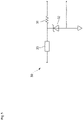
- the barrier circuit 30 has at least a current limiting element 31 that limits the current flowing in the sensor unit 12 to a predetermined current value or less and a voltage limiting element 32 that limits the voltage applied to the sensor unit 12 to a predetermined voltage value or less.
- the barrier circuit 30 further has a protection element 33 that protects the voltage limiting element 32.
- the oil mist detection device 100 of this embodiment further comprises a bulkhead member 40 that seals the explosion-proof area (X) by being housed in the above-mentioned casing 11 as shown in Fig. 2 and the barrier circuit 30 is arranged in the non-explosion-proof area (Y) that is isolated from the explosion-proof area (X) by the bulkhead member 40.
- the bulkhead member 40 airtightly seals the oil mist inlet chamber 10c and the sensor housing chamber 10d as being the explosion-proof area (X) while the above-mentioned wiring member (P) penetrates the bulkhead member 40.
- the bulkhead member 40 is a roughly cylindrical shape arranged in the casing 11 so that a whole circumference of the outer peripheral surface of the bulkhead member 40 airtightly contacts an inner peripheral surface of the casing 11.
- the bulkhead member 40 of this embodiment is an elastic material made of resin such as a liquid gasket that becomes silicone rubber when cured and an outer diameter of the bulkhead member 40 tightly attaches to the inner wall of the casing 11.
- a material of the bulkhead member 40 is not limited to this, and may be changed as needed, for example, to glass or ceramics, as far as the material does not pass the gas.
- An inside of the oil mist detection device 100 (an inside of the casing 11 and an inside of the second casing 22) is partitioned by the bulkhead member 40 into the explosion-proof area (X) locating in a distal end side from the bulkhead member 40 and the non-explosion-proof area (Y) locating in a proximal end side from the bulkhead member 40.
- the explosion-proof area (X) is an area arranged inside the crankcase (C)
- the non-explosion-proof area (Y) is an area arranged outside the crankcase (C). With this arrangement, no gas circulates between the explosion-proof area (X) and the non-explosion-proof area (Y).
- the above-mentioned barrier circuit 30 is arranged in the non-explosion-proof area (Y).
- the oil mist detection device 100 of this embodiment is so configured to prevent the gas from flowing from the explosion-proof area (X) to the non-explosion-proof area (Y) caused by the wiring member (P).
- the wiring member (P) is, for example, a twisted wire consisting of a plurality of conductors (wires) twisted together
- the gas in the crankcase (C) slips through a gap between a plurality of the conductors (wires) that constitute the twisted wire and flows from the explosion-proof area (X) to the non-explosion-proof area (Y).
- a plurality of the wiring members (P) connect the sensor unit 12 and the barrier circuit 30 without the wiring members (P) being in touch each other, namely, in state wherein each of the wiring members is non-contact.
- the wiring members (P) are linear or pin-shaped metal referred to as a single wire or a single needle and used in a state that the surface of the wiring member (P) is exposed without being covered by a coating material such as an insulating member.
- All of the outer peripheral surface of the wiring members (P) airtightly make contact with the inner peripheral surface of a through bore formed in the bulkhead member 40 so that the wiring members (P) penetrate the bulkhead member 40 without any gap through which the gas can pass.
- the barrier circuit 30 is arranged in the non-explosion-proof area (Y), it is possible to implement the barrier circuit 30 and the sensor unit 12, which require explosion-proof measures, in a single device.
- the bulkhead member 40 is the elastic body made of resin and has good adhesion, it is possible to securely seal the explosion-proof area (X).
- the invention is not limited to the above-mentioned embodiment.
- the bulkhead member 40 is cylindrical, however, it may be concave or convex as shown in Fig. 4 , and in short, the bulkhead member 40 may be changed to various shapes as far as the entire circumference of the outer peripheral surface of the bulkhead member 40 is airtightly attached to the inner peripheral surface of the casing 11.
- the explosion-proof area (X) may extend partly to the outside of the crankcase (C) as shown in an upper part of Fig. 5
- the non-explosion-proof area (Y) may extend partly to the inside part of the crankcase (C) as shown in a lower part of Fig. 5 .
Landscapes
- Chemical & Material Sciences (AREA)
- Health & Medical Sciences (AREA)
- Life Sciences & Earth Sciences (AREA)
- Biochemistry (AREA)
- Pathology (AREA)
- Immunology (AREA)
- General Physics & Mathematics (AREA)
- General Health & Medical Sciences (AREA)
- Physics & Mathematics (AREA)
- Analytical Chemistry (AREA)
- Engineering & Computer Science (AREA)
- Oil, Petroleum & Natural Gas (AREA)
- Medicinal Chemistry (AREA)
- Food Science & Technology (AREA)
- General Chemical & Material Sciences (AREA)
- Chemical Kinetics & Catalysis (AREA)
- Investigating Or Analysing Materials By Optical Means (AREA)
- Lubrication Details And Ventilation Of Internal Combustion Engines (AREA)
Abstract
Description
- This invention relates to an oil mist detection device that detects oil mist.
- As shown in Patent Document 1, there is an oil mist detection device of this type that is mounted on, for example, a crankcase of an internal combustion engine for ship and that detects oil mist generated in the crankcase.
- In recent years, environmental regulations have led to the use of a natural gas as fuel for internal combustion engines in place of a conventional heavy oil. In such cases, since the oil mist detection device is exposed to an explosive (flammable) natural gas, it is required to take explosion-proof measures. As concrete measures, for example, it is required to adopt an intrinsically safe explosion-proof structure, in which a barrier circuit is required to be provided to limit the energy supplied to a sensor unit of the oil mist detection device.
- However, in case of using a device with a barrier circuit that is separated from the oil mist detection device, a manufacturing cost of the separated device would be high. In addition, even if a conventional oil mist detection device comprises a barrier circuit, since the barrier circuit is in danger of being exposed to the natural gas, resulting in failure of meeting the requirements.
- Patent document 1:
Japanese unexamined patent application publication No. 2008-157648 - A main object of this invention is to provide an oil mist detection device having unprecedentedly explosion-proof specification without incurring a high cost.
- The oil mist detection device in accordance with the present claimed invention is an oil mist detection device that detects oil mist in a casing and that comprises a sensor unit that is housed in the casing and arranged in an explosion-proof area that requires explosion-proof measures, a wiring member that is connected to the sensor unit, a barrier circuit that is connected to the sensor unit through the wiring member, and a bulkhead member through which the wiring member penetrates and that is housed in the casing and that seals the explosion-proof area, and is characterized by that the barrier circuit is arranged in a non-explosion-proof area that is isolated from the explosion-proof area by the bulkhead member.
- In accordance with the oil mist detection device having the above-mentioned configuration, since the barrier circuit is arranged in the non-explosion-proof area, it is possible to implement the barrier circuit and the sensor unit that is required to be explosion-proof in a single device.
- With this arrangement, there is no need of manufacturing a device comprising a barrier circuit separated from the oil mist detection device so that it is possible to provide the oil mist detection device of the explosion-proof specification without incurring higher costs.
- For example, in case that a twisted wire consisting of multiple conductors is used to connect the sensor unit to the barrier circuit, a gas in the crankcase might slip through the gaps between a plurality of the conductors that constitute the twisted wire and might flow from the explosion-proof area into the non-explosion-proof area.
- In order to prevent the gas from slipping through, it is preferable that a plurality of the wiring members connect the sensor unit and the barrier circuit in a state wherein each of the wiring members is non-contact.
- In order to prevent the gas from slipping though more securely, it is preferable that the wiring member is a single wire.
- Even in case that the wiring member is covered with an insulating member, the gas in the crank case might slip through between the gap between the insulating member and the wiring member, Then, it is preferable that the wiring member connects the sensor unit and the barrier circuit without being covered by an insulating member.
- If there is a gap between the wiring member and the bulkhead member, the gas in the crank will flow from the explosion-proof area to the non-explosion-proof area through the gap. Then, it is preferable that the wiring member airtightly penetrates the bulkhead member.
- It is preferable that the bulkhead member is an elastic body made of resin.
- In accordance with this arrangement, it is possible to allow the bulkhead member to adhere closely to the casing so that the explosion-proof area can be sealed securely.
- As an embodiment of the barrier circuit that meets requirements for explosion-proof measures represented is the barrier circuit that limits the energy supplied to the sensor unit.
- In accordance with the present claimed invention having the above-mentioned configuration, it is possible to provide an unprecedented explosion-proof oil mist detection device without incurring high costs.
-
- [
Fig. 1 ] A schematic diagram showing an overall configuration of an oil mist detection device of this embodiment. - [
Fig. 2 ] A schematic diagram showing an internal configuration of the oil mist detection device of this embodiment. - [
Fig. 3 ] A circuit diagram showing a configuration of a barrier circuit of this embodiment. - [
Fig. 4 ] A schematic diagram showing a shape of a bulkhead member of other embodiments. - [
Fig. 5 ] A schematic diagram showing an internal configuration of the oil mist detection device of the other embodiment. -
- 100
- oil mist detection device
- C
- crankcase
- 10
- detection section
- 10a
- inlet port
- 10b
- outlet port
- 10c
- oil mist inlet chamber
- 10d
- sensor housing chamber
- 11
- casing
- 12
- sensor unit
- 13
- light emitting section
- 14
- light receiving section
- 15
- substrate
- W
- translucent window
- 20
- control section
- 21
- computer circuit
- 22
- second casing
- P
- wiring member
- 30
- barrier circuit
- 40
- bulkhead member
- X
- explosion-proof area
- Y
- non-explosion-proof area
- One embodiment of an oil mist detection device in accordance with the present claimed invention is explained below with reference to drawings.
- As shown in
Fig. 1 , the oilmist detection device 100 of this embodiment is a light scattering type that is mounted on a crankcase (C) of an internal combustion engine, for example, for ship and is used to detect oil mist generated in the crankcase (C) due to overheating of a bearing. The application of the oilmist detection device 100 is not limited to this, and it may also be used on internal combustion engines other than ships. - Concretely, the oil
mist detection device 100 comprises adetection section 10 that is mounted on a mounting bore arranged on a wall of the crank case (C) from the outside in a state wherein a distal end side of thedetection section 10 protrudes to an inside of the crankcase (C) and acontrol section 20 that is connected to a proximal end of thedetection section 10. - As shown in
Fig. 1 andFig. 2 , thedetection section 10 has acasing 11 and asensor unit 12 that is housed in thecasing 11. - The
casing 11 is in a generally cylindrical shape with a sealed distal end surface and has an oilmist inlet port 10a that leads the oil mist to the inside of thecasing 11 and an oilmist outlet port 10b that is formed to discharge the oil mist to the outside thereof. Screw threads (not shown in drawings) that are screwed into the mounting bore of the crankcase (C) are formed on an outer peripheral surface of thecasing 11. - As shown in
Fig. 2 , an oilmist inlet chamber 10c is formed on the distal end side of thecasing 11 to introduce and diffuse the oil mist into the casing 1, and asensor housing chamber 10d is formed on the proximal end side of thecasing 11 to accommodate thesensor unit 12. A translucent window (W) such as a lens is interposed between the oilmist inlet chamber 10c and thesensor housing chamber 10d so that the oil mist is prevented from flowing from the oilmist inlet chamber 10c into thesensor housing chamber 10d. - The
sensor unit 12 detects the oil mist introduced into the oilmist inlet chamber 10c and comprises alight emitting section 13 and alight receiving section 14. - The
light emitting section 13 is, for example, LEDs with its respective light emitting surface arranged to face the translucent window (W). In this embodiment used is thelight emitting section 13 that emits wavelength band light that conforms to a particle size of the oil mist. It is a matter of course that otherlight emitting section 13 such as LDs (laser diodes) may also be used. - The
light receiving section 14 is, for example, PDs (photo diodes) with its respective light receiving surface arranged to face the translucent window (W) and outputs an electrical signal corresponding to an intensity of the light received on its light receiving surface. It is a matter of course that otherlight receiving section 14 such as, for example, CCDs may also be used. - The irradiation light emitted from the
light emitting section 13 is irradiated to the oil mist introduced into the oilmist inlet chamber 10c through the translucent window (W), and the scattered light produced by this is received by thelight receiving section 14 after passing through the translucent window (W). - The
light emitting section 13 and thelight receiving section 14 are arranged in parallel so that the optical axes of the emitted light and the optical axis of the received light are parallel to each other, and thelight emitting section 13 and thelight receiving section 14 are mounted, for example, on an identicalsame substrate 15. However, the optical axes of thelight emitting section 13 andlight receiving section 14 are not necessarily parallel, and thelight emitting section 13 andlight receiving section 14 may be mounted on separate substrates. - The
substrate 15, together with thelight emitting section 13 and thelight receiving section 14, constitutes thesensor unit 12 and is housed in thesensor housing chamber 10d. One or more wiring members (P) are connected to thissubstrate 15, and thesensor unit 12 and thecontrol section 20 are connected by the wiring members (P). - One or more wiring members (P) are provided. In this embodiment, some wiring member (P) is to supply energy (current and/or voltage) from the
control section 20 to thelight emitting section 13 and some wiring member (P) is to transmit a detection signal which is an electrical signal corresponding to the intensity of the scattered light received by thelight receiving section 14 to thecontrol section 20. - The
control section 20 is structurally a so-called computer circuit 21 having a CPU, an internal memory, an AD converter or the like. Thecontrol section 20 performs information processing by operating according to programs stored in a predetermined area of the internal memory. In this embodiment, thecontrol section 20 detects whether there is the oil mist or not based on the detection signal transmitted from thelight receiving section 14 or measures the concentration of the oil mist based on the detection signal. - The
control section 20 further comprises asecond casing 22 that houses the above-mentioned computer circuit 21. An internal space of thesecond casing 22 forms thesensor housing chamber 10d by communicating with the internal space of thecasing 11 that constitutes the above-mentioneddetection section 10. In this embodiment, thesecond casing 22 has an approximate cylindrical shape, however, it may also have, for example, a rectangular shape. - In case that an explosive (flammable) gas such as a natural gas is used as the fuel for ships, since the explosive gas is supplied to the inside of the crankcase (C), at least a part arranged in the crankcase (C), into which the explosive gas can flow, of the oil
mist detection device 100, more concretely a part in the crankcase (C) into which the explosive gas can flow is an explosion-proof area (X) where explosion-proof measures are required. - If explained in more detail, in case that the explosive gas is supplied to the crankcase (C), since the explosive gas is introduced into the above-mentioned oil
mist inlet chamber 10c, the oilmist inlet chamber 10c is the explosion-proof area (X) that requires explosion-proof measures. In this embodiment, since there is no component constituting the oilmist inlet chamber 10c that requires explosion-proof measures, there is no need of taking concrete explosion-proof measures for the oilmist inlet chamber 10c. - On the other hand, although the
sensor housing chamber 10d and the oilmist inlet chamber 10c are partitioned by the translucent window (W), there is a small gap through which the gas can pass and that is interposed between thesensor housing chamber 10d and the oilmist inlet chamber 10c. With this arrangement, since the explosive gas flows into thesensor housing chamber 10d, thesensor housing chamber 10d also is the explosion-proof area (X) that requires explosion-proof measures. In addition, since thesensor unit 12 is arranged in thissensor housing chamber 10d, and thelight emitting section 13, thelight receiving section 14, and thesubstrate 15 that constitute thesensor unit 12 can be an ignition source, the concrete intrinsically safe explosion-proof measures are required for thesensor housing chamber 10d. - As shown in
Fig. 2 , the oilmist detection device 100 of this embodiment further comprises abarrier circuit 30 that is connected to thesensor unit 12 through the wiring member (P) and that limits the energy supplied to thesensor unit 12. - The
barrier circuit 30 of this embodiment is arranged on the same substrate as the computer circuit 21 that constitutes the above-mentionedcontrol section 20 and is housed in thesecond casing 22. Thebarrier circuit 30 may be arranged on a substrate separated from the computer circuit 21. - The
barrier circuit 30 is to secure the intrinsically safe explosion-proof structure of the oilmist detection device 100 and comprises a function to limit the energy supplied to thesensor unit 12 so that various electronic components that constituts thesensor unit 12 cannot be an ignition source. Concretely, as shown inFig. 3 , thebarrier circuit 30 has at least a current limitingelement 31 that limits the current flowing in thesensor unit 12 to a predetermined current value or less and avoltage limiting element 32 that limits the voltage applied to thesensor unit 12 to a predetermined voltage value or less. In this embodiment, thebarrier circuit 30 further has aprotection element 33 that protects thevoltage limiting element 32. - Then, the oil
mist detection device 100 of this embodiment further comprises abulkhead member 40 that seals the explosion-proof area (X) by being housed in the above-mentionedcasing 11 as shown inFig. 2 and thebarrier circuit 30 is arranged in the non-explosion-proof area (Y) that is isolated from the explosion-proof area (X) by thebulkhead member 40. - If explained in more detail, the
bulkhead member 40 airtightly seals the oilmist inlet chamber 10c and thesensor housing chamber 10d as being the explosion-proof area (X) while the above-mentioned wiring member (P) penetrates thebulkhead member 40. Concretely, thebulkhead member 40 is a roughly cylindrical shape arranged in thecasing 11 so that a whole circumference of the outer peripheral surface of thebulkhead member 40 airtightly contacts an inner peripheral surface of thecasing 11. - In addition, the
bulkhead member 40 of this embodiment is an elastic material made of resin such as a liquid gasket that becomes silicone rubber when cured and an outer diameter of thebulkhead member 40 tightly attaches to the inner wall of thecasing 11. A material of thebulkhead member 40 is not limited to this, and may be changed as needed, for example, to glass or ceramics, as far as the material does not pass the gas. - An inside of the oil mist detection device 100 (an inside of the
casing 11 and an inside of the second casing 22) is partitioned by thebulkhead member 40 into the explosion-proof area (X) locating in a distal end side from thebulkhead member 40 and the non-explosion-proof area (Y) locating in a proximal end side from thebulkhead member 40. In this embodiment, the explosion-proof area (X) is an area arranged inside the crankcase (C), and the non-explosion-proof area (Y) is an area arranged outside the crankcase (C). With this arrangement, no gas circulates between the explosion-proof area (X) and the non-explosion-proof area (Y). The above-mentionedbarrier circuit 30 is arranged in the non-explosion-proof area (Y). - The oil
mist detection device 100 of this embodiment is so configured to prevent the gas from flowing from the explosion-proof area (X) to the non-explosion-proof area (Y) caused by the wiring member (P). - Concretely, if the wiring member (P) is, for example, a twisted wire consisting of a plurality of conductors (wires) twisted together, the gas in the crankcase (C) slips through a gap between a plurality of the conductors (wires) that constitute the twisted wire and flows from the explosion-proof area (X) to the non-explosion-proof area (Y).
- Then in this embodiment, a plurality of the wiring members (P) connect the
sensor unit 12 and thebarrier circuit 30 without the wiring members (P) being in touch each other, namely, in state wherein each of the wiring members is non-contact. - More concretely, the wiring members (P) are linear or pin-shaped metal referred to as a single wire or a single needle and used in a state that the surface of the wiring member (P) is exposed without being covered by a coating material such as an insulating member.
- All of the outer peripheral surface of the wiring members (P) airtightly make contact with the inner peripheral surface of a through bore formed in the
bulkhead member 40 so that the wiring members (P) penetrate thebulkhead member 40 without any gap through which the gas can pass. - In accordance with the oil
mist detection device 100 having the above-mentioned configuration, since thebarrier circuit 30 is arranged in the non-explosion-proof area (Y), it is possible to implement thebarrier circuit 30 and thesensor unit 12, which require explosion-proof measures, in a single device. - With this configuration, there is no need of manufacturing a device comprising a
barrier circuit 30 separated from the oilmist detection device 100 so that it is possible to provide the oilmist detection device 100 of the explosion-proof specification without incurring higher costs. - In addition, since a single wire or a single needle that does not contact each other is used as a plurality of the wiring members (P) without using twisted wires, it is possible to prevent the gas from slipping through that occurs in case that twisted wires are used. In addition, since the wiring members (P) airtightly penetrate the
bulkhead member 40 without being covered by a covering member, it is possible to securely prevent the gas from flowing from the explosion-proof area (X) to the non-explosion-proof area (Y). - Furthermore, since the
bulkhead member 40 is the elastic body made of resin and has good adhesion, it is possible to securely seal the explosion-proof area (X). - The invention is not limited to the above-mentioned embodiment.
- For example, in the above-mentioned embodiment, the
bulkhead member 40 is cylindrical, however, it may be concave or convex as shown inFig. 4 , and in short, thebulkhead member 40 may be changed to various shapes as far as the entire circumference of the outer peripheral surface of thebulkhead member 40 is airtightly attached to the inner peripheral surface of thecasing 11. - In addition, the explosion-proof area (X) may extend partly to the outside of the crankcase (C) as shown in an upper part of
Fig. 5 , and the non-explosion-proof area (Y) may extend partly to the inside part of the crankcase (C) as shown in a lower part ofFig. 5 . - It is a matter of course that the present claimed invention is not limited to the above-mentioned embodiments, and various other variations are possible without departing from the spirit of the invention.
- In accordance with the present claimed invention, it is possible to provide an unprecedented explosion-proof oil mist detection device without incurring higher costs.
Claims (7)
- An oil mist detection device that detects oil mist in a casing and that comprisesa sensor unit that is housed in the casing and arranged in an explosion-proof area that requires explosion-proof measures,a wiring member that is connected to the sensor unit,a barrier circuit that is connected to the sensor unit through the wiring member, anda bulkhead member through which the wiring member penetrates and that is housed in the casing and that seals the explosion-proof area, whereinthe barrier circuit is arranged in a non-explosion-proof area that is isolated from the explosion-proof area by the bulkhead member.
- The oil mist detection device described in claim 1, wherein a plurality of the wiring members connect the sensor unit and the barrier circuit in a state wherein each of the wiring members is non-contact.
- The oil mist detection device described in claim 1 or 2, wherein the wiring member is a single wire.
- The oil mist detection device described in either one of claim 1 through claim 3, wherein the wiring member connects the sensor unit and the barrier circuit without being covered by an insulating member.
- The oil mist detection device described in either one of claim 1 through claim 4, wherein the wiring member airtightly penetrates the bulkhead member.
- The oil mist detection device described in either one of claim 1 through claim 5, wherein the bulkhead member is an elastic body made of resin.
- The oil mist detection device described in either one of claim 1 through claim 6, wherein the barrier circuit limits energy supplied to the sensor unit.
Applications Claiming Priority (2)
| Application Number | Priority Date | Filing Date | Title |
|---|---|---|---|
| JP2019217277A JP7388894B2 (en) | 2019-11-29 | 2019-11-29 | Oil mist detection device |
| PCT/JP2020/044003 WO2021107004A1 (en) | 2019-11-29 | 2020-11-26 | Oil mist detection device |
Publications (2)
| Publication Number | Publication Date |
|---|---|
| EP4067877A1 true EP4067877A1 (en) | 2022-10-05 |
| EP4067877A4 EP4067877A4 (en) | 2023-12-20 |
Family
ID=76087762
Family Applications (1)
| Application Number | Title | Priority Date | Filing Date |
|---|---|---|---|
| EP20894901.6A Pending EP4067877A4 (en) | 2019-11-29 | 2020-11-26 | OIL DISPERSION DETECTION DEVICE |
Country Status (5)
| Country | Link |
|---|---|
| EP (1) | EP4067877A4 (en) |
| JP (1) | JP7388894B2 (en) |
| KR (1) | KR102929357B1 (en) |
| CN (1) | CN114729884B (en) |
| WO (1) | WO2021107004A1 (en) |
Families Citing this family (1)
| Publication number | Priority date | Publication date | Assignee | Title |
|---|---|---|---|---|
| JP7691293B2 (en) * | 2021-07-07 | 2025-06-11 | 明陽電機株式会社 | Oil mist measuring device |
Family Cites Families (20)
| Publication number | Priority date | Publication date | Assignee | Title |
|---|---|---|---|---|
| US4841157A (en) * | 1988-01-06 | 1989-06-20 | Downing Jr John P | Optical backscatter turbidimeter sensor |
| JPH05249038A (en) * | 1992-03-06 | 1993-09-28 | Tabai Espec Corp | Oil mist concentration measuring apparatus |
| EP0766086A3 (en) * | 1995-09-29 | 2000-01-19 | Ngk Insulators, Ltd. | Multiple element particle sensor and signal processing electronics |
| JP3869384B2 (en) | 2003-04-01 | 2007-01-17 | 大起理化工業株式会社 | Sampling aid |
| JP2006145397A (en) * | 2004-11-19 | 2006-06-08 | Denso Corp | Gas sensor |
| JP4414915B2 (en) | 2004-12-02 | 2010-02-17 | エナジーサポート株式会社 | Gas analyzer |
| JP4757044B2 (en) * | 2006-01-27 | 2011-08-24 | オリンパス株式会社 | Explosion-proof device drive |
| JP5032836B2 (en) * | 2006-12-21 | 2012-09-26 | 株式会社堀場製作所 | Oil mist detection device |
| KR100880147B1 (en) * | 2008-05-23 | 2009-01-23 | 주식회사 스펙스 | Oil mist detector |
| JP5415123B2 (en) | 2009-03-31 | 2014-02-12 | 日本碍子株式会社 | Gripping jig, and measuring device and gripping apparatus using the same |
| EP3979634A1 (en) * | 2009-06-16 | 2022-04-06 | Leonard Pool | Intrinsically safe video inspection system |
| KR101153901B1 (en) * | 2010-05-18 | 2012-06-18 | (주)광산 | Oil mist detecting apparatus |
| CN103424334A (en) * | 2012-05-24 | 2013-12-04 | 上海海事大学 | Oil mist concentration measurement device and method based on micro-differential pressure measurement |
| DE102012105379B3 (en) | 2012-06-21 | 2013-07-25 | Bernd Donner | Sensor and method for measuring particles in media |
| JP5973399B2 (en) | 2013-09-11 | 2016-08-23 | 株式会社クボタ | Optical grain evaluation device and combine equipped with optical grain evaluation device |
| WO2016145119A1 (en) * | 2015-03-09 | 2016-09-15 | Spectrasensors, Inc. | Intrinsically safe spectroscopic analyzer |
| JP6522404B2 (en) * | 2015-04-22 | 2019-05-29 | 株式会社堀場製作所 | Oil mist detection device, oil mist detection method |
| RU2687141C1 (en) | 2015-08-25 | 2019-05-07 | Фенвал Контролз Оф Джэпэн, Лтд. | Photoelectric smoke detector |
| CN109073619A (en) | 2016-02-12 | 2018-12-21 | 德康有限公司 | wireless gas detection sensor |
| US10670054B2 (en) * | 2017-10-25 | 2020-06-02 | Dresser, Llc | Constructing valve positioners for hazardous areas |
-
2019
- 2019-11-29 JP JP2019217277A patent/JP7388894B2/en active Active
-
2020
- 2020-11-26 EP EP20894901.6A patent/EP4067877A4/en active Pending
- 2020-11-26 WO PCT/JP2020/044003 patent/WO2021107004A1/en not_active Ceased
- 2020-11-26 CN CN202080081802.3A patent/CN114729884B/en active Active
- 2020-11-26 KR KR1020227017888A patent/KR102929357B1/en active Active
Also Published As
| Publication number | Publication date |
|---|---|
| CN114729884B (en) | 2025-06-20 |
| CN114729884A (en) | 2022-07-08 |
| JP2021085854A (en) | 2021-06-03 |
| KR102929357B1 (en) | 2026-02-23 |
| KR20220104173A (en) | 2022-07-26 |
| EP4067877A4 (en) | 2023-12-20 |
| WO2021107004A1 (en) | 2021-06-03 |
| JP7388894B2 (en) | 2023-11-29 |
Similar Documents
| Publication | Publication Date | Title |
|---|---|---|
| JP6510709B2 (en) | Sensor unit and pressure detection device including the same | |
| EP2647979A1 (en) | Speed reducer for industrial robot | |
| RU2665351C2 (en) | Wire sealing for the detector unit | |
| WO2012074109A1 (en) | Lubricating oil degradation sensor | |
| KR102929357B1 (en) | Oil mist detection device | |
| CN1237860C (en) | Electronic equipment having its casing | |
| US11605918B2 (en) | Protection device for a plug-in connection | |
| EP1818667A2 (en) | Gas sensor | |
| CN112823452A (en) | Plug-in connector | |
| EP1034421B1 (en) | Liquid level gauge | |
| HUP9602509A2 (en) | A probe with one side protruding cap | |
| HK40076472B (en) | Oil mist detection device | |
| HK40076472A (en) | Oil mist detection device | |
| EP3859288B1 (en) | Electro-optic sensor | |
| ES2183580T3 (en) | CONTROL SYSTEM FOR AN INTERNAL COMBUSTION ENGINE, WITH A SENSOR AND WITH AN INTERCONNECTION POINT FOR DIGITALIZING MEASURED VALUES. | |
| KR102554162B1 (en) | Photoelectric smoke detector | |
| US20160363552A1 (en) | Electrically Conductive Fluid Detector | |
| US7244895B1 (en) | Electrical feedthrough for varied environmental conditions | |
| CN213600669U (en) | Explosion-proof structure of diffusion type gas detection probe | |
| KR101079699B1 (en) | portable explosion-proof computer | |
| CN112654816B (en) | lighting device | |
| US5044753A (en) | Environmentally sealed colorimeter for industrial environments | |
| US20240410558A1 (en) | Electrical appliance with housing | |
| US20050023027A1 (en) | Illuminating bus cable | |
| US20240288299A1 (en) | Level measuring device for use in high-pressure applications |
Legal Events
| Date | Code | Title | Description |
|---|---|---|---|
| STAA | Information on the status of an ep patent application or granted ep patent |
Free format text: STATUS: THE INTERNATIONAL PUBLICATION HAS BEEN MADE |
|
| PUAI | Public reference made under article 153(3) epc to a published international application that has entered the european phase |
Free format text: ORIGINAL CODE: 0009012 |
|
| STAA | Information on the status of an ep patent application or granted ep patent |
Free format text: STATUS: REQUEST FOR EXAMINATION WAS MADE |
|
| 17P | Request for examination filed |
Effective date: 20220615 |
|
| AK | Designated contracting states |
Kind code of ref document: A1 Designated state(s): AL AT BE BG CH CY CZ DE DK EE ES FI FR GB GR HR HU IE IS IT LI LT LU LV MC MK MT NL NO PL PT RO RS SE SI SK SM TR |
|
| DAV | Request for validation of the european patent (deleted) | ||
| DAX | Request for extension of the european patent (deleted) | ||
| REG | Reference to a national code |
Ref country code: DE Ref legal event code: R079 Free format text: PREVIOUS MAIN CLASS: G01N0021490000 Ipc: G01N0021530000 |
|
| A4 | Supplementary search report drawn up and despatched |
Effective date: 20231121 |
|
| RIC1 | Information provided on ipc code assigned before grant |
Ipc: G01N 33/28 20060101ALN20231115BHEP Ipc: G01N 21/47 20060101ALN20231115BHEP Ipc: H02H 9/00 20060101ALI20231115BHEP Ipc: G01N 21/85 20060101ALI20231115BHEP Ipc: G01N 21/53 20060101AFI20231115BHEP |
|
| STAA | Information on the status of an ep patent application or granted ep patent |
Free format text: STATUS: EXAMINATION IS IN PROGRESS |
|
| 17Q | First examination report despatched |
Effective date: 20250630 |
|
| RAP3 | Party data changed (applicant data changed or rights of an application transferred) |
Owner name: DAIHATSU INFINEARTH MFG. CO., LTD. Owner name: HORIBA, LTD. |