EP4067845A1 - Skin color chart and method for preparing same - Google Patents
Skin color chart and method for preparing same Download PDFInfo
- Publication number
- EP4067845A1 EP4067845A1 EP19954703.5A EP19954703A EP4067845A1 EP 4067845 A1 EP4067845 A1 EP 4067845A1 EP 19954703 A EP19954703 A EP 19954703A EP 4067845 A1 EP4067845 A1 EP 4067845A1
- Authority
- EP
- European Patent Office
- Prior art keywords
- skin color
- display part
- color display
- skin
- substrate
- Prior art date
- Legal status (The legal status is an assumption and is not a legal conclusion. Google has not performed a legal analysis and makes no representation as to the accuracy of the status listed.)
- Granted
Links
Images


Classifications
-
- G—PHYSICS
- G01—MEASURING; TESTING
- G01J—MEASUREMENT OF INTENSITY, VELOCITY, SPECTRAL CONTENT, POLARISATION, PHASE OR PULSE CHARACTERISTICS OF INFRARED, VISIBLE OR ULTRAVIOLET LIGHT; COLORIMETRY; RADIATION PYROMETRY
- G01J3/00—Spectrometry; Spectrophotometry; Monochromators; Measuring colours
- G01J3/46—Measurement of colour; Colour measuring devices, e.g. colorimeters
- G01J3/52—Measurement of colour; Colour measuring devices, e.g. colorimeters using colour charts
-
- G—PHYSICS
- G09—EDUCATION; CRYPTOGRAPHY; DISPLAY; ADVERTISING; SEALS
- G09F—DISPLAYING; ADVERTISING; SIGNS; LABELS OR NAME-PLATES; SEALS
- G09F5/00—Means for displaying samples
- G09F5/04—Cards of samples; Books of samples
-
- G—PHYSICS
- G01—MEASURING; TESTING
- G01J—MEASUREMENT OF INTENSITY, VELOCITY, SPECTRAL CONTENT, POLARISATION, PHASE OR PULSE CHARACTERISTICS OF INFRARED, VISIBLE OR ULTRAVIOLET LIGHT; COLORIMETRY; RADIATION PYROMETRY
- G01J3/00—Spectrometry; Spectrophotometry; Monochromators; Measuring colours
- G01J3/46—Measurement of colour; Colour measuring devices, e.g. colorimeters
-
- G—PHYSICS
- G06—COMPUTING OR CALCULATING; COUNTING
- G06V—IMAGE OR VIDEO RECOGNITION OR UNDERSTANDING
- G06V40/00—Recognition of biometric, human-related or animal-related patterns in image or video data
- G06V40/10—Human or animal bodies, e.g. vehicle occupants or pedestrians; Body parts, e.g. hands
- G06V40/16—Human faces, e.g. facial parts, sketches or expressions
- G06V40/161—Detection; Localisation; Normalisation
- G06V40/162—Detection; Localisation; Normalisation using pixel segmentation or colour matching
Definitions
- the present disclosure relates to a skin color chart and a method for manufacturing the same.
- a face authentication environment the environment for performing face authentication (hereinafter referred to as a face authentication environment) is appropriate.
- the face authentication environment varies depending on, for example, the position where a camera is installed, the orientation of the camera, and the brightness of a place where a face image is captured.
- Patent Literature 1 discloses a skin color chart for evaluating skin color reproduction in a color photograph or the like.
- Patent Literature 1 Japanese Unexamined Patent Application Publication No. 2001-074556
- the inventor has found the following problem as a result of examining a case where a skin color chart is captured by a camera and then a face authentication environment is determined using the acquired image of the skin color chart.
- the skin color chart disclosed in Patent Literature 1 is used for evaluating skin color reproduction in a color photograph or the like, and includes an average Caucasoid skin color display part and an average Negroid skin color display part.
- the face authentication environment is determined using this skin color chart, it is determined that the environment is suitable for face authentication, for example, if no blown-out highlights occur in the Caucasoid skin color display part and no blocked-up shadows occur in the Negroid skin color display part in the acquired image of the skin color chart.
- an object of the present disclosure is to provide a skin color chart that enables a more appropriate determination of a face authentication environment and a method for manufacturing the same.
- a skin color chart according to the present disclosure is a skin color chart for determining an environment where face authentication is performed, the skin color chart including:
- a method for manufacturing a skin color chart according to the present disclosure is a method for manufacturing a skin color chart for determining an environment where face authentication is performed, the method including:
- Fig. 1 is a plan view showing the skin color chart according to the first example embodiment.
- a skin color chart 10 according to the first example embodiment shown in Fig. 1 is a chart for determining a face authentication environment.
- the skin color chart 10 includes a substrate 11, a first skin color display part BK, and a second skin color display part WT.
- the substrate 11 is made of, for example, cardboard, plastic, wood, metal, glass and combinations thereof, but is not limited to being made of any particular material.
- the substrate 11 is made of cardboard, plastic, and wood, it is lightweight and thus can be easily carried.
- the substrate 11 has a rectangular planar shape, but is not limited thereto.
- the width of the substrate 11 is about 200 mm and the length thereof is about 300 mm, but the size of the substrate 11 is not limited to a particular size.
- the first skin color display part BK is formed on the substrate 11.
- the first skin color display part BK shows a skin color near the limit of the distribution of the skin colors of black people on the blackest part of the distribution.
- colors can be defined using a CIE L ⁇ a ⁇ b ⁇ color space standardized by the International Commission on Illumination (CIE) in 1976.
- Lightness L ⁇ of a skin color in the first skin color display part BK expressed in the CIE L ⁇ a ⁇ b ⁇ color space satisfies 20 ⁇ L ⁇ ⁇ 37.
- An average skin color of Negroid is lighter than the aforementioned skin color and the value of L ⁇ is greater than 37.
- the lightness L ⁇ is more preferably 20 ⁇ L ⁇ ⁇ 29.
- chromaticity a ⁇ and chromaticity b ⁇ of the first skin color display part BK satisfy, for example, 8 ⁇ a ⁇ ⁇ 12 and 7 ⁇ b ⁇ ⁇ 10, respectively.
- the chromaticity a ⁇ and the chromaticity b ⁇ are more preferably 9 ⁇ a ⁇ ⁇ 11 and 8 ⁇ b ⁇ ⁇ 9, respectively.
- the first skin color display part BK has a square planar shape, but is not limited thereto.
- the second skin color display part WT is also formed on the substrate 11.
- the second skin color display part WT shows a skin color near the limit of the distribution of the skin colors of white people on the whitest part of the distribution.
- lightness L ⁇ of a skin color in the second skin color display part WT expressed in the CIE L ⁇ a ⁇ b ⁇ color space satisfies 74 ⁇ L ⁇ ⁇ 81.
- An average skin color of Caucasoid is darker than the aforementioned skin color and the value of L ⁇ is smaller than 74.
- the lightness L ⁇ is more preferably 78 ⁇ L ⁇ ⁇ 81.
- chromaticity a ⁇ and chromaticity b ⁇ of the second skin color display part WT satisfy, for example, 10 ⁇ a ⁇ ⁇ 12 and 23 ⁇ b ⁇ ⁇ 25, respectively.
- the first skin color display part BK has a square planar shape, but is not limited thereto.
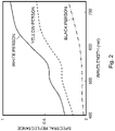
- Fig. 2 is a graph showing an example of a spectral reflectance of a skin color of each of Negroid, Caucasoid, and Mongoloid.
- the horizontal axis indicates wavelengths (nm), and the vertical axis indicates the spectral reflectance.
- the highest spectral reflectance is that of the Caucasoid
- the second highest spectral reflectance is that of the Mongoloid
- the lowest spectral reflectance is that of the Negroid.
- the values of L ⁇ , a ⁇ , and b ⁇ in the corresponding CIE L ⁇ a ⁇ b ⁇ color space are obtained together with data of a spectral reflectance like the one shown in Fig. 2 .
- a large amount of data of L ⁇ , a ⁇ , and b ⁇ of the skin colors of black and white people are acquired and then a range of the aforementioned values can be determined.
- the skin color chart 10 is captured by a camera for face authentication (not shown). Then, in the captured image of the skin color chart 10, it can be determined that the environment is suitable for face authentication if blocked-up shadows do not occur in the first skin color display part BK and blown-out highlights do not occur in the second skin color display part WT.
- the lightness L ⁇ of the skin color in the first skin color display part BK satisfies 20 ⁇ L ⁇ ⁇ 37
- the first skin color display part BK shows the skin color near the limit of the distribution of the skin colors of black people on the blackest part of the distribution.
- the lightness L ⁇ of the skin color in the second skin color display part WT satisfies 74 ⁇ L ⁇ ⁇ 81, and the second skin color display part WT shows the skin color near the limit of the distribution of the skin colors of white people on the whitest part of the distribution.
- the first skin color display part BK is formed on the substrate 11 and the second skin color display part WT is formed on the same.
- One of the first skin color display part BK and the second skin color display part WT may be formed first on the substrate 11, or these two display parts may be formed simultaneously.
- the first skin color display part BK and the second skin color display part WT prepared in advance are stuck on a mount made of cardboard.
- paints that have been adjusted to the colors of the first skin color display part BK and the second skin color display part WT are respectively applied to pieces of paper, whereby the first skin color display part BK and the second skin color display part WT can be prepared.
- the paint is, for example, a non-glossy lacquer paint, but is not limited to a particular paint.
- a black cardboard of the same size as that of the mount is prepared, and parts of the black cardboard corresponding to the first skin color display part BK and the second skin color display part WT that have been stuck on the mount are cut out. Then the black cardboard and the mount on which the first skin color display part BK and the second skin color display part WT have been stuck are bonded to each other. Note that the black cardboard has been processed so that the reflectance of the surface thereof becomes 0 (zero).
- the skin color chart 10 can be manufactured.
- the substrate 11 is formed of a mount and a black cardboard.
- the first skin color display part BK shows the skin color near the limit of the distribution of the skin colors of black people on the blackest part of the distribution
- the second skin color display part WT shows the skin color near the limit of the distribution of the skin colors of white people on the whitest part of the distribution.
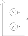
- Fig. 3 is a plan view showing the skin color chart according to the second example embodiment.
- each of the first skin color display part BK and the second skin color display part WT is formed in a flat shape (formed so as to be flat).
- each of the first skin color display part BK and the second skin color display part WT is formed in a three-dimensional shape imitating a human face. That is, in each of the first skin color display part BK and the second skin color display part WT, projections and recesses imitating a human face are formed.
- blocked-up shadows may occur in a recessed part of the face (e.g., a part of the face near the shadow formed by the nose) in the face image of Negroid, and hence there is a possibility that face authentication cannot be performed even in the environment which it has been determined is suitable for face authentication.
- blown-out highlights may occur in a projection part of the face (e.g., a part of the face near the top of the nose) in the face image of Caucasoid, and hence there is a possibility that face authentication cannot be performed.
- the skin color chart 10 according to the second example embodiment when a face authentication environment is determined, it is possible to determine that the environment in which blocked-up shadows occur in the recessed part and the like of the first skin color display part BK is not suitable for face authentication. Further, it is possible to determine that the environment in which blown-out highlights occur in the projection part and the like of the second skin color display part WT is also not suitable for face authentication.
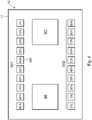
- Fig. 4 is a plan view showing the skin color chart according to the third example embodiment.
- the skin color chart 10 includes, in addition to the first skin color display part BK and the second skin color display part WT, gray scale parts GS1 and GS2 formed of a plurality of gray display parts GR having different reflectances.
- each of the two gray scale parts GS1 and GS2 includes 10 of the gray display parts GR having reflectances of 2 to 90%.
- the reflectances of the gray display parts GR are 2%, 10%, 20%, 30%, 40%, 50%, 60%, 70%, 80%, and 90%.
- the 10 gray display parts GR are arranged in a row along the long side of the rectangular skin color chart 10. Further, the gray scale parts GS1 and GS2 are disposed so as to be opposed to each other with the first skin color display part BK and the second skin color display part WT interposed therebetween.
- gray scale parts GS1 and GS2 By using the gray scale parts GS1 and GS2, it is possible, for example, to evaluate the dynamic range of the camera for face authentication (not shown) and adjust it.
- each of the gray display parts GR has a square planar shape, but is not limited thereto. Further, the number of gray display parts GR included in the gray scale parts GS1 and GS2 and the reflectance of each of the gray display parts GR may be determined as appropriate. Further, the number of gray scale parts may be one.
- the structures other than the above ones are similar to those of the first example embodiment, and thus the descriptions thereof will be omitted.
- the second example embodiment may be combined with the third example embodiment.
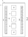
- Fig. 5 is a plan view showing the skin color chart according to the fourth example embodiment.
- the skin color chart 10 according to this example embodiment includes a third skin color display part YL in addition to the skin color chart 10 according to the third example embodiment.
- the third skin color display part YL is formed on the substrate 11.
- the position where the third skin color display part YL is disposed is not limited to a particular position; in the example shown in Fig. 5 , the third skin color display part YL is disposed between the first skin color display part BK and the second skin color display part WT.
- the third skin color display part YL shows a skin color between the skin color in the first skin color display part BK and the skin color in the second skin color display part WT.
- the third skin color display part YL shows, for example, an average skin color of Mongoloid.
- lightness L ⁇ of a skin color in the third skin color display part YL expressed in the CIE L ⁇ a ⁇ b ⁇ color space satisfies, for example, 62 ⁇ L ⁇ ⁇ 68.
- the third skin color display part YL when a face authentication environment is being determined, it is possible to evaluate the environment in more detail than it is in the cases of the first to the third example embodiments. Specifically, it can be understood that the environment in which blocked-up shadows occur in the third skin color display part YL in addition to the first skin color display part BK is blacker than the environment in which blocked-up shadows occur only in the first skin color display part BK. It can also be understood that the environment in which blown-out highlights occur in the third skin color display part YL in addition to the second skin color display part WT is brighter than the environment in which blown-out highlights occur only in the second skin color display part WT. Based on the above-described evaluations, for example, the position where a camera is installed, the orientation of the camera, and the brightness of a place where a face image is captured can be easily adjusted.
- the third skin color display part YL has a square planar shape, but is not limited thereto.
- the structures other than the above ones are similar to those of the third example embodiment, and thus the descriptions thereof will be omitted.
- the second example embodiment may be combined with the fourth example embodiment. Further, in the fourth example embodiment, the gray scale parts GS1 and GS2 may not be formed. That is, a structure in which the third skin color display part YL is added to the skin color chart 10 according to the first example embodiment may be employed.
- Fig. 6 is a plan view showing the skin color chart according to the fifth example embodiment.
- the skin color chart 10 includes a fourth skin color display part 14 and a fifth skin color display part 15 in addition to the skin color chart 10 according to the fourth example embodiment.
- the fourth skin color display part 14 and the fifth skin color display part 15 are also formed on the substrate 11.
- the position where the fourth skin color display part 14 is disposed and the position where the fifth skin color display part 15 is disposed are not limited to particular positions; in the example shown in Fig. 6 , the fourth skin color display part 14 is disposed between the first skin color display part BK and the third skin color display part YL. Further, the fifth skin color display part 15 is disposed between the second skin color display part WT and the third skin color display part YL.
- the fourth skin color display part 14 shows a skin color between the skin color in the first skin color display part BK and the skin color in the third skin color display part YL.
- the fifth skin color display part 15 shows a skin color between the skin color in the second skin color display part WT and the skin color in the third skin color display part YL.
- the fourth skin color display part 14 when a face authentication environment is being determined, the environment can be evaluated in much more detail than it is in the case of the fourth example embodiment. Specifically, it is possible to distinguish the environment in which blocked-up shadows occur in the first skin color display part BK and the fourth skin color display part 14 from the environment in which blocked-up shadows occur only in the first skin color display part BK. Further, it is possible to distinguish the environment in which blocked-up shadows occur in the first skin color display part BK, the fourth skin color display part 14, and the third skin color display part YL from the environment in which blocked-up shadows occur only in the first skin color display part BK and the fourth skin color display part 14.
- the environment can be evaluated in much more detail than it is in the case of the fourth example embodiment. Specifically, it is possible to distinguish the environment in which blown-out highlights occur in the second skin color display part WT and the fifth skin color display part 15 from the environment in which blown-out highlights occur only in the second skin color display part WT. Further, it is possible to distinguish the environment in which blown-out highlights occur in the second skin color display part WT, the fifth skin color display part 15, and the third skin color display part YL from the environment in which blown-out highlights occur only in the second skin color display part WT and the fifth skin color display part 15.
- the position where a camera is installed the orientation of the camera, and the brightness of a place where a face image is captured can be more easily adjusted.
- each of the fourth skin color display part 14 and the fifth skin color display part 15 has a square planar shape, but is not limited thereto. Further, the skin color chart 10 may include only one of the fourth skin color display part 14 and the fifth skin color display part 15.
- a plurality of fourth skin color display parts 14 showing skin colors different from each other may be provided in the skin color chart 10.
- a plurality of fifth skin color display parts 15 showing skin colors different from each other may be provided in the skin color chart 10.
- the skin colors of the third skin color display part YL, the fourth skin color display part 14, and the fifth skin color display part 15 may show, for example, average skin colors in specific countries or regions.
- the structures other than the above ones are similar to those of the fourth example embodiment, and thus the descriptions thereof will be omitted.
- the second example embodiment may be combined with the fifth example embodiment.
- the gray scale parts GS1 and GS2 may not be formed. That is, a structure in which the third skin color display part YL, the fourth skin color display part 14, and the fifth skin color display part 15 are added to the skin color chart 10 according to the first example embodiment may be employed.
- a skin color chart for determining an environment where face authentication is performed comprising:
- each of the first and the second skin color display parts is formed in a three-dimensional shape imitating a human face.
- the skin color chart according to Supplementary note 1 or 2 further comprising a plurality of gray display parts having different reflectances, the gray display parts being formed on the substrate.
- the skin color chart according to any one of Supplementary notes 1 to 3, further comprising a third skin color display part configured to show a skin color between the skin color in the first skin color display part and the skin color in the second skin color display part, the third skin color display part being formed on the substrate, wherein lightness L ⁇ of the third skin color display part in the CIE L ⁇ a ⁇ b ⁇ color space satisfies 62 ⁇ L ⁇ ⁇ 68.
- the skin color chart according to Supplementary note 4 further comprising, on the substrate, at least one of:
- the skin color chart according to any one of Supplementary notes 1 to 5, wherein the substrate is black.
- a method for manufacturing a skin color chart for determining an environment where face authentication is performed comprising:
- each of the first and the second skin color display parts is formed in a three-dimensional shape imitating a human face.
Landscapes
- Physics & Mathematics (AREA)
- Spectroscopy & Molecular Physics (AREA)
- General Physics & Mathematics (AREA)
- Engineering & Computer Science (AREA)
- Theoretical Computer Science (AREA)
- Image Processing (AREA)
- Spectrometry And Color Measurement (AREA)
- Measurement Of The Respiration, Hearing Ability, Form, And Blood Characteristics Of Living Organisms (AREA)
Abstract
Description
- The present disclosure relates to a skin color chart and a method for manufacturing the same.
- In recent years, a face authentication system that specifies a person by using a face image of the person captured by a camera has been developed. Note that, in the face image of a person with white skin such as Caucasoid, blown-out highlights tend to occur in a bright environment, and in the face image of a person with black skin such as Negroid, blocked-up shadows tend to occur in a dark environment.
- When such blown-out highlights or blocked-up shadows occur in the face image, face authentication may not be performed accurately. Therefore, for example, when a camera for a face authentication system is installed, it is necessary to determine whether or not the environment for performing face authentication (hereinafter referred to as a face authentication environment) is appropriate. The face authentication environment varies depending on, for example, the position where a camera is installed, the orientation of the camera, and the brightness of a place where a face image is captured.
- Incidentally,
Patent Literature 1 discloses a skin color chart for evaluating skin color reproduction in a color photograph or the like. - Note that, in this specification, the terms "Negroid", "Caucasoid", and "Mongoloid" are used in order to describe differences in skin color; however, the use of these terms is not intended to discriminate against any race.
- Patent Literature 1:
Japanese Unexamined Patent Application Publication No. 2001-074556 - The inventor has found the following problem as a result of examining a case where a skin color chart is captured by a camera and then a face authentication environment is determined using the acquired image of the skin color chart.
- As described above, the skin color chart disclosed in
Patent Literature 1 is used for evaluating skin color reproduction in a color photograph or the like, and includes an average Caucasoid skin color display part and an average Negroid skin color display part. When the face authentication environment is determined using this skin color chart, it is determined that the environment is suitable for face authentication, for example, if no blown-out highlights occur in the Caucasoid skin color display part and no blocked-up shadows occur in the Negroid skin color display part in the acquired image of the skin color chart. - However, even in the environment which it has been determined using the skin color chart disclosed in
Patent Literature 1 is suitable for face authentication, face authentication may not be performed accurately. Specifically, even in the environment which it has been determined is suitable for face authentication, the environment may actually be too dark and blocked-up shadows may occur in the face image of a person whose skin is blacker than the average Negroid skin color display part in the skin color chart. Conversely, the environment may actually be too bright and blown-out highlights may occur in the face image of a person whose skin is whiter than the average Caucasoid skin color display part in the skin color chart. - In view of the problem described above, an object of the present disclosure is to provide a skin color chart that enables a more appropriate determination of a face authentication environment and a method for manufacturing the same.
- A skin color chart according to the present disclosure is a skin color chart for determining an environment where face authentication is performed, the skin color chart including:
- a substrate;
- a first skin color display part configured to show a skin color of a Negroid, the first skin color display part being formed on the substrate; and
- a second skin color display part configured to show a skin color of a Caucasoid, the second skin color display part being formed on the substrate, in which
- lightness L∗ of the first skin color display part in a CIE L∗a∗b∗ color space satisfies 20≤L∗≤37, and
- lightness L∗ of the second skin color display part in the CIE L∗a∗b∗ color space satisfies 74≤L∗≤81.
- A method for manufacturing a skin color chart according to the present disclosure is a method for manufacturing a skin color chart for determining an environment where face authentication is performed, the method including:
- forming, on a substrate, a first skin color display part configured to show a skin color of a Negroid; and
- forming, on the substrate, a second skin color display part configured to show a skin color of a Caucasoid, in which
- lightness L∗ of the first skin color display part in a CIE L∗a∗b∗ color space satisfies 20≤L∗≤37, and
- lightness L∗ of the second skin color display part in the CIE L∗a∗b∗ color space satisfies 74≤L∗≤81.
- According to the present disclosure, it is possible to provide a skin color chart that enables a more appropriate determination of a face authentication environment and a method for manufacturing the same.
-
-
Fig. 1 is a plan view showing a skin color chart according to a first example embodiment; -
Fig. 2 is a graph showing an example of a spectral reflectance of a skin color of each of Negroid, Caucasoid, and Mongoloid; -
Fig. 3 is a plan view showing a skin color chart according to a second example embodiment; -
Fig. 4 is a plan view showing a skin color chart according to a third example embodiment; -
Fig. 5 is a plan view showing a skin color chart according to a fourth example embodiment; and -
Fig. 6 is a plan view showing a skin color chart according to a fifth example embodiment. - Specific example embodiments will be described hereinafter in detail with reference to the drawings. The same or corresponding elements are denoted by the same reference symbols throughout the drawings, and redundant descriptions will be omitted as necessary for the clarification of the description.
- First, a skin color chart according to a first example embodiment will be described with reference to
Fig. 1. Fig. 1 is a plan view showing the skin color chart according to the first example embodiment. Askin color chart 10 according to the first example embodiment shown inFig. 1 is a chart for determining a face authentication environment. - As shown in
Fig. 1 , theskin color chart 10 according to the first example embodiment includes asubstrate 11, a first skin color display part BK, and a second skin color display part WT. - The
substrate 11 is made of, for example, cardboard, plastic, wood, metal, glass and combinations thereof, but is not limited to being made of any particular material. When thesubstrate 11 is made of cardboard, plastic, and wood, it is lightweight and thus can be easily carried. In the example shown inFig. 1 , thesubstrate 11 has a rectangular planar shape, but is not limited thereto. As an example, the width of thesubstrate 11 is about 200 mm and the length thereof is about 300 mm, but the size of thesubstrate 11 is not limited to a particular size. In order to prevent reflection, it is preferable that, for example, the color of thesubstrate 11 be black having a reflectance of 0, but the color of thesubstrate 11 is not limited to a particular color. - As shown in
Fig. 1 , the first skin color display part BK is formed on thesubstrate 11. The first skin color display part BK shows a skin color near the limit of the distribution of the skin colors of black people on the blackest part of the distribution. Specifically, colors can be defined using a CIE L∗a∗b∗ color space standardized by the International Commission on Illumination (CIE) in 1976. Lightness L∗ of a skin color in the first skin color display part BK expressed in the CIE L∗a∗b∗ color space satisfies 20≤L∗≤37. An average skin color of Negroid is lighter than the aforementioned skin color and the value of L∗ is greater than 37. The lightness L∗ is more preferably 20≤L∗≤29. - Further, chromaticity a∗ and chromaticity b∗ of the first skin color display part BK satisfy, for example, 8≤a∗≤12 and 7≤b∗≤10, respectively. The chromaticity a∗ and the chromaticity b∗ are more preferably 9≤a∗≤11 and 8≤b∗≤9, respectively.
- Note that, in the example shown in
Fig. 1 , the first skin color display part BK has a square planar shape, but is not limited thereto. - As shown in
Fig. 1 , the second skin color display part WT is also formed on thesubstrate 11. The second skin color display part WT shows a skin color near the limit of the distribution of the skin colors of white people on the whitest part of the distribution. Specifically, lightness L∗ of a skin color in the second skin color display part WT expressed in the CIE L∗a∗b∗ color space satisfies 74≤L∗≤81. An average skin color of Caucasoid is darker than the aforementioned skin color and the value of L∗ is smaller than 74. The lightness L∗ is more preferably 78≤L∗≤81. - Further, chromaticity a∗ and chromaticity b∗ of the second skin color display part WT satisfy, for example, 10≤a∗≤12 and 23≤b∗≤25, respectively. The chromaticity a∗ and the chromaticity b∗ are more preferably a∗=11 and b∗=24, respectively.
- Note that, in the example shown in
Fig. 1 , the first skin color display part BK has a square planar shape, but is not limited thereto. - Note that
Fig. 2 is a graph showing an example of a spectral reflectance of a skin color of each of Negroid, Caucasoid, and Mongoloid. InFig. 2 , the horizontal axis indicates wavelengths (nm), and the vertical axis indicates the spectral reflectance. As shown inFig. 2 , at each wavelength, the highest spectral reflectance is that of the Caucasoid, the second highest spectral reflectance is that of the Mongoloid, and the lowest spectral reflectance is that of the Negroid. For example, when measurement is performed using a spectrophotometric colorimeter, the values of L∗, a∗, and b∗ in the corresponding CIE L∗a∗b∗ color space are obtained together with data of a spectral reflectance like the one shown inFig. 2 . A large amount of data of L∗, a∗, and b∗ of the skin colors of black and white people are acquired and then a range of the aforementioned values can be determined. - When a face authentication environment is determined using the
skin color chart 10, theskin color chart 10 is captured by a camera for face authentication (not shown). Then, in the captured image of theskin color chart 10, it can be determined that the environment is suitable for face authentication if blocked-up shadows do not occur in the first skin color display part BK and blown-out highlights do not occur in the second skin color display part WT. - As described above, in the
skin color chart 10 according to this example embodiment, the lightness L∗ of the skin color in the first skin color display part BK satisfies 20≤L∗≤37, and the first skin color display part BK shows the skin color near the limit of the distribution of the skin colors of black people on the blackest part of the distribution. Thus, it is extremely unlikely that a person whose skin is blacker than the first skin color display part BK will be a person on whom face authentication is to be performed. Therefore, in the environment which it has been determined using theskin color chart 10 according to this example embodiment is suitable for face authentication, it is also extremely unlikely that blocked-up shadows will occur in the face image and then face authentication cannot be performed. - On the other hand, the lightness L∗ of the skin color in the second skin color display part WT satisfies 74≤L∗≤81, and the second skin color display part WT shows the skin color near the limit of the distribution of the skin colors of white people on the whitest part of the distribution. Thus, it is extremely unlikely that a person whose skin is whiter than the second skin color display part WT will be a person on whom face authentication is to be performed. Therefore, in the environment which it has been determined using the
skin color chart 10 according to this example embodiment is suitable for face authentication, it is also extremely unlikely that blown-out highlights will occur in the face image and then face authentication cannot be performed. - As described above, by using the
skin color chart 10 according to this example embodiment, it is possible to more appropriately determine a face authentication environment. - Next, a method for manufacturing a skin color chart according to the first example embodiment will be described with reference to
Fig. 1 . The first skin color display part BK is formed on thesubstrate 11 and the second skin color display part WT is formed on the same. One of the first skin color display part BK and the second skin color display part WT may be formed first on thesubstrate 11, or these two display parts may be formed simultaneously. - Although a specific example of a method for manufacturing a skin color chart according to the first example embodiment will be described below, the method is not limited to this specific example.
- First, the first skin color display part BK and the second skin color display part WT prepared in advance are stuck on a mount made of cardboard. For example, paints that have been adjusted to the colors of the first skin color display part BK and the second skin color display part WT are respectively applied to pieces of paper, whereby the first skin color display part BK and the second skin color display part WT can be prepared. The paint is, for example, a non-glossy lacquer paint, but is not limited to a particular paint.
- Next, a black cardboard of the same size as that of the mount is prepared, and parts of the black cardboard corresponding to the first skin color display part BK and the second skin color display part WT that have been stuck on the mount are cut out. Then the black cardboard and the mount on which the first skin color display part BK and the second skin color display part WT have been stuck are bonded to each other. Note that the black cardboard has been processed so that the reflectance of the surface thereof becomes 0 (zero).
- In this way, the
skin color chart 10 can be manufactured. In theskin color chart 10 manufactured according to this specific example, thesubstrate 11 is formed of a mount and a black cardboard. - As described above, in the
skin color chart 10 according to this example embodiment, the first skin color display part BK shows the skin color near the limit of the distribution of the skin colors of black people on the blackest part of the distribution, and the second skin color display part WT shows the skin color near the limit of the distribution of the skin colors of white people on the whitest part of the distribution. Thus, it is extremely unlikely that a person whose skin is blacker than the first skin color display part BK or a person whose skin is whiter than the second skin color display part WT will be a person on whom face authentication is to be performed. Therefore, in the environment which it has been determined using theskin color chart 10 according to this example embodiment is suitable for face authentication, it is also extremely unlikely that blocked-up shadows or blown-out highlights will occur in the face image and then face authentication cannot be performed. That is, by using theskin color chart 10 according to this example embodiment, it is possible to more appropriately determine a face authentication environment. - Next, a skin color chart according to a second example embodiment will be described with reference to
Fig. 3. Fig. 3 is a plan view showing the skin color chart according to the second example embodiment. - In the
skin color chart 10 according to the first example embodiment shown inFig. 1 , each of the first skin color display part BK and the second skin color display part WT is formed in a flat shape (formed so as to be flat). On the other hand, in theskin color chart 10 according to the second example embodiment shown inFig. 3 , each of the first skin color display part BK and the second skin color display part WT is formed in a three-dimensional shape imitating a human face. That is, in each of the first skin color display part BK and the second skin color display part WT, projections and recesses imitating a human face are formed. - In a case in which the
skin color chart 10 according to the first example embodiment is used, for example, blocked-up shadows may occur in a recessed part of the face (e.g., a part of the face near the shadow formed by the nose) in the face image of Negroid, and hence there is a possibility that face authentication cannot be performed even in the environment which it has been determined is suitable for face authentication. Alternatively, for example, blown-out highlights may occur in a projection part of the face (e.g., a part of the face near the top of the nose) in the face image of Caucasoid, and hence there is a possibility that face authentication cannot be performed. - On the other hand, in a case in which the
skin color chart 10 according to the second example embodiment is used, when a face authentication environment is determined, it is possible to determine that the environment in which blocked-up shadows occur in the recessed part and the like of the first skin color display part BK is not suitable for face authentication. Further, it is possible to determine that the environment in which blown-out highlights occur in the projection part and the like of the second skin color display part WT is also not suitable for face authentication. - Therefore, by using the
skin color chart 10 according to this example embodiment, it is possible to further appropriately determine a face authentication environment. - The structures other than the above ones are similar to those of the first example embodiment, and thus the descriptions thereof will be omitted.
- Next, a skin color chart according to a third example embodiment will be described with reference to
Fig. 4. Fig. 4 is a plan view showing the skin color chart according to the third example embodiment. - As shown in
Fig. 4 , theskin color chart 10 according to this example embodiment includes, in addition to the first skin color display part BK and the second skin color display part WT, gray scale parts GS1 and GS2 formed of a plurality of gray display parts GR having different reflectances. - In the example shown in
Fig. 4 , each of the two gray scale parts GS1 and GS2 includes 10 of the gray display parts GR having reflectances of 2 to 90%. Specifically, the reflectances of the gray display parts GR are 2%, 10%, 20%, 30%, 40%, 50%, 60%, 70%, 80%, and 90%. - In the example shown in
Fig. 4 , in the gray scale parts GS1 and GS2, the 10 gray display parts GR are arranged in a row along the long side of the rectangularskin color chart 10. Further, the gray scale parts GS1 and GS2 are disposed so as to be opposed to each other with the first skin color display part BK and the second skin color display part WT interposed therebetween. - By using the gray scale parts GS1 and GS2, it is possible, for example, to evaluate the dynamic range of the camera for face authentication (not shown) and adjust it.
- Note that, in the example shown in
Fig. 4 , each of the gray display parts GR has a square planar shape, but is not limited thereto. Further, the number of gray display parts GR included in the gray scale parts GS1 and GS2 and the reflectance of each of the gray display parts GR may be determined as appropriate. Further, the number of gray scale parts may be one. - The structures other than the above ones are similar to those of the first example embodiment, and thus the descriptions thereof will be omitted. The second example embodiment may be combined with the third example embodiment.
- Next, a skin color chart according to a fourth example embodiment will be described with reference to
Fig. 5. Fig. 5 is a plan view showing the skin color chart according to the fourth example embodiment. - As shown in
Fig. 5 , theskin color chart 10 according to this example embodiment includes a third skin color display part YL in addition to theskin color chart 10 according to the third example embodiment. - As shown in
Fig. 5 , the third skin color display part YL, like the first skin color display part BK and the second skin color display part WT, is formed on thesubstrate 11. The position where the third skin color display part YL is disposed is not limited to a particular position; in the example shown inFig. 5 , the third skin color display part YL is disposed between the first skin color display part BK and the second skin color display part WT. - The third skin color display part YL shows a skin color between the skin color in the first skin color display part BK and the skin color in the second skin color display part WT. The third skin color display part YL shows, for example, an average skin color of Mongoloid. Specifically, lightness L∗ of a skin color in the third skin color display part YL expressed in the CIE L∗a∗b∗ color space satisfies, for example, 62≤L∗≤68. Further, chromaticity a∗ and chromaticity b∗ of the third skin color display part YL satisfy, for example, a∗=11 and 18≤b∗≤19, respectively.
- By providing the third skin color display part YL, when a face authentication environment is being determined, it is possible to evaluate the environment in more detail than it is in the cases of the first to the third example embodiments. Specifically, it can be understood that the environment in which blocked-up shadows occur in the third skin color display part YL in addition to the first skin color display part BK is blacker than the environment in which blocked-up shadows occur only in the first skin color display part BK. It can also be understood that the environment in which blown-out highlights occur in the third skin color display part YL in addition to the second skin color display part WT is brighter than the environment in which blown-out highlights occur only in the second skin color display part WT. Based on the above-described evaluations, for example, the position where a camera is installed, the orientation of the camera, and the brightness of a place where a face image is captured can be easily adjusted.
- Note that, in the example shown in
Fig. 5 , the third skin color display part YL has a square planar shape, but is not limited thereto. - The structures other than the above ones are similar to those of the third example embodiment, and thus the descriptions thereof will be omitted. The second example embodiment may be combined with the fourth example embodiment. Further, in the fourth example embodiment, the gray scale parts GS1 and GS2 may not be formed. That is, a structure in which the third skin color display part YL is added to the
skin color chart 10 according to the first example embodiment may be employed. - Next, a skin color chart according to a fifth example embodiment will be described with reference to
Fig. 6. Fig. 6 is a plan view showing the skin color chart according to the fifth example embodiment. - As shown in
Fig. 6 , theskin color chart 10 according to this example embodiment includes a fourth skincolor display part 14 and a fifth skincolor display part 15 in addition to theskin color chart 10 according to the fourth example embodiment. - As shown in
Fig. 6 , the fourth skincolor display part 14 and the fifth skincolor display part 15 are also formed on thesubstrate 11. The position where the fourth skincolor display part 14 is disposed and the position where the fifth skincolor display part 15 is disposed are not limited to particular positions; in the example shown inFig. 6 , the fourth skincolor display part 14 is disposed between the first skin color display part BK and the third skin color display part YL. Further, the fifth skincolor display part 15 is disposed between the second skin color display part WT and the third skin color display part YL. - The fourth skin
color display part 14 shows a skin color between the skin color in the first skin color display part BK and the skin color in the third skin color display part YL. - The fifth skin
color display part 15 shows a skin color between the skin color in the second skin color display part WT and the skin color in the third skin color display part YL. - By providing the fourth skin
color display part 14, when a face authentication environment is being determined, the environment can be evaluated in much more detail than it is in the case of the fourth example embodiment. Specifically, it is possible to distinguish the environment in which blocked-up shadows occur in the first skin color display part BK and the fourth skincolor display part 14 from the environment in which blocked-up shadows occur only in the first skin color display part BK. Further, it is possible to distinguish the environment in which blocked-up shadows occur in the first skin color display part BK, the fourth skincolor display part 14, and the third skin color display part YL from the environment in which blocked-up shadows occur only in the first skin color display part BK and the fourth skincolor display part 14. - Similarly, by providing the fifth skin
color display part 15, when a face authentication environment is being determined, the environment can be evaluated in much more detail than it is in the case of the fourth example embodiment. Specifically, it is possible to distinguish the environment in which blown-out highlights occur in the second skin color display part WT and the fifth skincolor display part 15 from the environment in which blown-out highlights occur only in the second skin color display part WT. Further, it is possible to distinguish the environment in which blown-out highlights occur in the second skin color display part WT, the fifth skincolor display part 15, and the third skin color display part YL from the environment in which blown-out highlights occur only in the second skin color display part WT and the fifth skincolor display part 15. - Based on the above-described evaluations, for example, the position where a camera is installed, the orientation of the camera, and the brightness of a place where a face image is captured can be more easily adjusted.
- Note that, in the example shown in
Fig. 6 , each of the fourth skincolor display part 14 and the fifth skincolor display part 15 has a square planar shape, but is not limited thereto. Further, theskin color chart 10 may include only one of the fourth skincolor display part 14 and the fifth skincolor display part 15. - Further, a plurality of fourth skin
color display parts 14 showing skin colors different from each other may be provided in theskin color chart 10. Similarly, a plurality of fifth skincolor display parts 15 showing skin colors different from each other may be provided in theskin color chart 10. - Further, in this example embodiment, the skin colors of the third skin color display part YL, the fourth skin
color display part 14, and the fifth skincolor display part 15 may show, for example, average skin colors in specific countries or regions. - The structures other than the above ones are similar to those of the fourth example embodiment, and thus the descriptions thereof will be omitted. The second example embodiment may be combined with the fifth example embodiment. Further, in the fifth example embodiment, the gray scale parts GS1 and GS2 may not be formed. That is, a structure in which the third skin color display part YL, the fourth skin
color display part 14, and the fifth skincolor display part 15 are added to theskin color chart 10 according to the first example embodiment may be employed. - Although the present disclosure has been described with reference to the example embodiments, the present disclosure is not limited to the above-described example embodiments. Various changes that may be understood by those skilled in the art may be made to the configurations and details of the present disclosure within the scope of the disclosure.
- The whole or part of the example embodiments disclosed above can be described as, but not limited to, the following supplementary notes.
- A skin color chart for determining an environment where face authentication is performed, the skin color chart comprising:
- a substrate;
- a first skin color display part configured to show a skin color of a Negroid, the first skin color display part being formed on the substrate; and
- a second skin color display part configured to show a skin color of a Caucasoid, the second skin color display part being formed on the substrate, wherein
- lightness L∗ of the first skin color display part in a CIE L∗a∗b∗ color space satisfies 20≤L∗≤37, and
- lightness L∗ of the second skin color display part in the CIE L∗a∗b∗ color space satisfies 74≤L∗≤81.
- The skin color chart according to
Supplementary note 1, wherein each of the first and the second skin color display parts is formed in a three-dimensional shape imitating a human face. - The skin color chart according to
Supplementary note - The skin color chart according to any one of
Supplementary notes 1 to 3, further comprising a third skin color display part configured to show a skin color between the skin color in the first skin color display part and the skin color in the second skin color display part, the third skin color display part being formed on the substrate,
wherein lightness L∗ of the third skin color display part in the CIE L∗a∗b∗ color space satisfies 62≤L∗≤68. - The skin color chart according to Supplementary note 4, further comprising, on the substrate, at least one of:
- a fourth skin color display part configured to show a skin color between the skin color in the first skin color display part and the skin color in the third skin color display part; and
- a fifth skin color display part configured to show a skin color between the skin color in the second skin color display part and the skin color in the third skin color display part.
- The skin color chart according to any one of
Supplementary notes 1 to 5, wherein the substrate is black. - A method for manufacturing a skin color chart for determining an environment where face authentication is performed, the method comprising:
- forming, on a substrate, a first skin color display part configured to show a skin color of a Negroid; and
- forming, on the substrate, a second skin color display part configured to show a skin color of a Caucasoid, wherein
- lightness L∗ of the first skin color display part in a CIE L∗a∗b∗ color space satisfies 20≤L∗≤37, and
- lightness L∗ of the second skin color display part in the CIE L∗a∗b∗ color space satisfies 74≤L∗≤81.
- The method according to Supplementary note 7, wherein each of the first and the second skin color display parts is formed in a three-dimensional shape imitating a human face.
- The method according to Supplementary note 7 or 8, further comprising forming a plurality of gray display parts having different reflectances on the substrate.
- The method according to any one of Supplementary notes 7 to 9, further comprising forming, on the substrate, a third skin color display part configured to show a skin color between the skin color in the first skin color display part and the skin color in the second skin color display part,
wherein lightness L∗ of the third skin color display part in the CIE L∗a∗b∗ color space satisfies 62≤L∗≤68. - The method according to
Supplementary note 10, further comprising forming, on the substrate, at least one of: - a fourth skin color display part configured to show a skin color between the skin color in the first skin color display part and the skin color in the third skin color display part; and
- a fifth skin color display part configured to show a skin color between the skin color in the second skin color display part and the skin color in the third skin color display part.
- The method according to any one of Supplementary notes 7 to 11, wherein the substrate is black.
-
- 10
- SKIN COLOR CHART
- 11
- SUBSTRATE
- BK
- FIRST SKIN COLOR DISPLAY PART
- WT
- SECOND SKIN COLOR DISPLAY PART
- YL
- THIRD SKIN COLOR DISPLAY PART
- 14
- FOURTH SKIN COLOR DISPLAY PART
- 15
- FIFTH SKIN COLOR DISPLAY PART
- GR
- GRAY DISPLAY PART
- GS1, GS2
- GRAY SCALE PART
Claims (12)
- A skin color chart for determining an environment where face authentication is performed, the skin color chart comprising:a substrate;a first skin color display part configured to show a skin color of a Negroid, the first skin color display part being formed on the substrate; anda second skin color display part configured to show a skin color of a Caucasoid, the second skin color display part being formed on the substrate, whereinlightness L∗ of the first skin color display part in a CIE L∗a∗b∗ color space satisfies 20≤L∗≤37, andlightness L∗ of the second skin color display part in the CIE L∗a∗b∗ color space satisfies 74≤L∗≤81.
- The skin color chart according to Claim 1, wherein each of the first and the second skin color display parts is formed in a three-dimensional shape imitating a human face.
- The skin color chart according to Claim 1 or 2, further comprising a plurality of gray display parts having different reflectances, the gray display parts being formed on the substrate.
- The skin color chart according to any one of Claims 1 to 3, further comprising a third skin color display part configured to show a skin color between the skin color in the first skin color display part and the skin color in the second skin color display part, the third skin color display part being formed on the sub strate,
wherein lightness L∗ of the third skin color display part in the CIE L∗a∗b∗ color space satisfies 62≤L∗≤68. - The skin color chart according to Claim 4, further comprising, on the substrate, at least one of:a fourth skin color display part configured to show a skin color between the skin color in the first skin color display part and the skin color in the third skin color display part; anda fifth skin color display part configured to show a skin color between the skin color in the second skin color display part and the skin color in the third skin color display part.
- The skin color chart according to any one of Claims 1 to 5, wherein the substrate is black.
- A method for manufacturing a skin color chart for determining an environment where face authentication is performed, the method comprising:forming, on a substrate, a first skin color display part configured to show a skin color of a Negroid; andforming, on the substrate, a second skin color display part configured to show a skin color of a Caucasoid, whereinlightness L∗ of the first skin color display part in a CIE L∗a∗b∗ color space satisfies 20≤L∗≤37, andlightness L∗ of the second skin color display part in the CIE L∗a∗b∗ color space satisfies 74≤L∗≤81.
- The method according to Claim 7, wherein each of the first and the second skin color display parts is formed in a three-dimensional shape imitating a human face.
- The method according to Claim 7 or 8, further comprising forming a plurality of gray display parts having different reflectances on the substrate.
- The method according to any one of Claims 7 to 9, further comprising forming, on the substrate, a third skin color display part configured to show a skin color between the skin color in the first skin color display part and the skin color in the second skin color display part,
wherein lightness L∗ of the third skin color display part in the CIE L∗a∗b∗ color space satisfies 62≤L∗≤68. - The method according to Claim 10, further comprising forming, on the substrate, at least one of:a fourth skin color display part configured to show a skin color between the skin color in the first skin color display part and the skin color in the third skin color display part; anda fifth skin color display part configured to show a skin color between the skin color in the second skin color display part and the skin color in the third skin color display part.
- The method according to any one of Claims 7 to 11, wherein the substrate is black.
Applications Claiming Priority (1)
| Application Number | Priority Date | Filing Date | Title |
|---|---|---|---|
| PCT/JP2019/046773 WO2021106192A1 (en) | 2019-11-29 | 2019-11-29 | Skin color chart and method for preparing same |
Publications (3)
| Publication Number | Publication Date |
|---|---|
| EP4067845A1 true EP4067845A1 (en) | 2022-10-05 |
| EP4067845A4 EP4067845A4 (en) | 2023-01-11 |
| EP4067845B1 EP4067845B1 (en) | 2025-12-31 |
Family
ID=76129422
Family Applications (1)
| Application Number | Title | Priority Date | Filing Date |
|---|---|---|---|
| EP19954703.5A Active EP4067845B1 (en) | 2019-11-29 | 2019-11-29 | SKIN COLOUR SCALE AND ITS PREPARATION PROCESS |
Country Status (4)
| Country | Link |
|---|---|
| US (1) | US20230026416A1 (en) |
| EP (1) | EP4067845B1 (en) |
| JP (1) | JP7251656B2 (en) |
| WO (1) | WO2021106192A1 (en) |
Families Citing this family (1)
| Publication number | Priority date | Publication date | Assignee | Title |
|---|---|---|---|---|
| WO2024023932A1 (en) * | 2022-07-26 | 2024-02-01 | 日本電気株式会社 | Test chart, image analysis device, image analysis system, image analysis method, and recording medium |
Family Cites Families (7)
| Publication number | Priority date | Publication date | Assignee | Title |
|---|---|---|---|---|
| JP2001074556A (en) * | 1999-09-03 | 2001-03-23 | Fuji Photo Film Co Ltd | Skin-colored color chart |
| FR2817746B1 (en) * | 2000-12-08 | 2005-03-11 | Oreal | NUANCIER REPRODUCING AN APPEARANCE CHARACTERISTIC OTHER THAN COLOR |
| FR2817745B1 (en) * | 2000-12-08 | 2003-03-28 | Oreal | MANUFACTURER AND METHOD OF MANUFACTURE |
| JP4102983B2 (en) * | 2002-09-20 | 2008-06-18 | ソニー株式会社 | Color chart set, color chart set generation method, color chart set generation apparatus, white balance performance measurement method, and image processing apparatus |
| JP2006081846A (en) * | 2004-09-17 | 2006-03-30 | Inforward Inc | Method and apparatus for estimating facial wrinkle |
| US20090080004A1 (en) * | 2007-09-26 | 2009-03-26 | Sony Corporation | System and method for determining an optimal reference color chart |
| EP2919185A4 (en) * | 2012-11-09 | 2016-07-13 | Fujifilm Corp | CAMERA SYSTEM, COLOR CONVERSION DEVICE AND ASSOCIATED METHOD, AND COLOR CONVERSION PROGRAM |
-
2019
- 2019-11-29 JP JP2021561104A patent/JP7251656B2/en active Active
- 2019-11-29 EP EP19954703.5A patent/EP4067845B1/en active Active
- 2019-11-29 US US17/777,660 patent/US20230026416A1/en active Pending
- 2019-11-29 WO PCT/JP2019/046773 patent/WO2021106192A1/en not_active Ceased
Also Published As
| Publication number | Publication date |
|---|---|
| EP4067845A4 (en) | 2023-01-11 |
| US20230026416A1 (en) | 2023-01-26 |
| JPWO2021106192A1 (en) | 2021-06-03 |
| EP4067845B1 (en) | 2025-12-31 |
| WO2021106192A1 (en) | 2021-06-03 |
| JP7251656B2 (en) | 2023-04-04 |
Similar Documents
| Publication | Publication Date | Title |
|---|---|---|
| EP2393061B1 (en) | Color image processing method, color image processing device and recording medium | |
| US20100228511A1 (en) | Method for managing metamerism of color merchandise | |
| US20240062509A1 (en) | Face authentication environment determination method, face authentication environment determination system, face authentication environment determination apparatus, and non-transitory computer readable medium | |
| EP3594658B1 (en) | Evaluator, measurement apparatus, evaluating method, and evaluating program | |
| JP3809838B2 (en) | Image highlight correction method using image source specific HSV color coordinates, image highlight correction program, and image acquisition system | |
| Bianconi et al. | On comparing colour spaces from a performance perspective: Application to automated classification of polished natural stones | |
| CN116817770A (en) | Method for detecting thickness of oxide layer of metal material based on chromaticity information | |
| US20230026416A1 (en) | Skin color chart and method for manufacturing the same | |
| US9036030B2 (en) | Color calibration of an image capture device in a way that is adaptive to the scene to be captured | |
| Hsu et al. | A novel automatic white balance method for color constancy under different color temperatures | |
| Prasad et al. | Metrics and statistics of frequency of occurrence of metamerism in consumer cameras for natural scenes | |
| US7659982B2 (en) | Quantitative evaluation of a color filter | |
| Liao et al. | Restoration of the distorted color to detect the discoloration status of a steel bridge coating using digital image measurements | |
| Gijsenij et al. | A perceptual comparison of distance measures for color constancy algorithms | |
| Van Song et al. | Towards spectral prediction of 2.5 d prints for soft-proofing applications | |
| US6922486B2 (en) | Process of identification of shadows in an image and image obtained using the process | |
| KR20100027105A (en) | Color-rendering index device | |
| US20240233114A1 (en) | Method and system for determining a pattern deviation value of a visible surface of a panel | |
| Hill | High quality color image reproduction: The multispectral solution | |
| Zhu et al. | Color calibration for colorized vision system with digital sensor and LED array illuminator | |
| JP2019153931A (en) | Measuring device, method for setting parameter for color measurement conversion in measuring device, and industrial product inspected by measuring device | |
| Crichton et al. | Skin chromaticity gamuts for illumination recovery | |
| JP7584024B1 (en) | Color correction chart | |
| WO2023119983A1 (en) | Color lens determination method, color lens determination device, and program | |
| Kirk | Chromaticity coordinates for graphic arts based on CIE 2006 LMS with even spacing of Munsell colours |
Legal Events
| Date | Code | Title | Description |
|---|---|---|---|
| STAA | Information on the status of an ep patent application or granted ep patent |
Free format text: STATUS: THE INTERNATIONAL PUBLICATION HAS BEEN MADE |
|
| PUAI | Public reference made under article 153(3) epc to a published international application that has entered the european phase |
Free format text: ORIGINAL CODE: 0009012 |
|
| STAA | Information on the status of an ep patent application or granted ep patent |
Free format text: STATUS: REQUEST FOR EXAMINATION WAS MADE |
|
| 17P | Request for examination filed |
Effective date: 20220616 |
|
| AK | Designated contracting states |
Kind code of ref document: A1 Designated state(s): AL AT BE BG CH CY CZ DE DK EE ES FI FR GB GR HR HU IE IS IT LI LT LU LV MC MK MT NL NO PL PT RO RS SE SI SK SM TR |
|
| A4 | Supplementary search report drawn up and despatched |
Effective date: 20221212 |
|
| RIC1 | Information provided on ipc code assigned before grant |
Ipc: G06V 40/00 20220101ALI20221206BHEP Ipc: G06V 10/60 20220101ALI20221206BHEP Ipc: G06V 10/56 20220101ALI20221206BHEP Ipc: G01J 3/52 20060101AFI20221206BHEP |
|
| DAV | Request for validation of the european patent (deleted) | ||
| DAX | Request for extension of the european patent (deleted) | ||
| GRAP | Despatch of communication of intention to grant a patent |
Free format text: ORIGINAL CODE: EPIDOSNIGR1 |
|
| STAA | Information on the status of an ep patent application or granted ep patent |
Free format text: STATUS: GRANT OF PATENT IS INTENDED |
|
| RIC1 | Information provided on ipc code assigned before grant |
Ipc: G01J 3/52 20060101AFI20250613BHEP Ipc: G06V 10/56 20220101ALI20250613BHEP Ipc: G06V 10/60 20220101ALI20250613BHEP Ipc: G06V 40/00 20220101ALI20250613BHEP |
|
| INTG | Intention to grant announced |
Effective date: 20250702 |
|
| GRAS | Grant fee paid |
Free format text: ORIGINAL CODE: EPIDOSNIGR3 |
|
| GRAA | (expected) grant |
Free format text: ORIGINAL CODE: 0009210 |
|
| STAA | Information on the status of an ep patent application or granted ep patent |
Free format text: STATUS: THE PATENT HAS BEEN GRANTED |
|
| AK | Designated contracting states |
Kind code of ref document: B1 Designated state(s): AL AT BE BG CH CY CZ DE DK EE ES FI FR GB GR HR HU IE IS IT LI LT LU LV MC MK MT NL NO PL PT RO RS SE SI SK SM TR |
|
| REG | Reference to a national code |
Ref country code: CH Ref legal event code: F10 Free format text: ST27 STATUS EVENT CODE: U-0-0-F10-F00 (AS PROVIDED BY THE NATIONAL OFFICE) Effective date: 20251231 Ref country code: GB Ref legal event code: FG4D |
|
| REG | Reference to a national code |
Ref country code: DE Ref legal event code: R096 Ref document number: 602019080003 Country of ref document: DE |
|
| REG | Reference to a national code |
Ref country code: IE Ref legal event code: FG4D |
|
| REG | Reference to a national code |
Ref country code: LT Ref legal event code: MG9D |
|
| PG25 | Lapsed in a contracting state [announced via postgrant information from national office to epo] |
Ref country code: NO Free format text: LAPSE BECAUSE OF FAILURE TO SUBMIT A TRANSLATION OF THE DESCRIPTION OR TO PAY THE FEE WITHIN THE PRESCRIBED TIME-LIMIT Effective date: 20260331 |
|
| PG25 | Lapsed in a contracting state [announced via postgrant information from national office to epo] |
Ref country code: FI Free format text: LAPSE BECAUSE OF FAILURE TO SUBMIT A TRANSLATION OF THE DESCRIPTION OR TO PAY THE FEE WITHIN THE PRESCRIBED TIME-LIMIT Effective date: 20251231 Ref country code: HR Free format text: LAPSE BECAUSE OF FAILURE TO SUBMIT A TRANSLATION OF THE DESCRIPTION OR TO PAY THE FEE WITHIN THE PRESCRIBED TIME-LIMIT Effective date: 20251231 |
|
| PG25 | Lapsed in a contracting state [announced via postgrant information from national office to epo] |
Ref country code: RS Free format text: LAPSE BECAUSE OF FAILURE TO SUBMIT A TRANSLATION OF THE DESCRIPTION OR TO PAY THE FEE WITHIN THE PRESCRIBED TIME-LIMIT Effective date: 20260331 |
|
| PG25 | Lapsed in a contracting state [announced via postgrant information from national office to epo] |
Ref country code: LV Free format text: LAPSE BECAUSE OF FAILURE TO SUBMIT A TRANSLATION OF THE DESCRIPTION OR TO PAY THE FEE WITHIN THE PRESCRIBED TIME-LIMIT Effective date: 20251231 |
|
| PG25 | Lapsed in a contracting state [announced via postgrant information from national office to epo] |
Ref country code: BG Free format text: LAPSE BECAUSE OF FAILURE TO SUBMIT A TRANSLATION OF THE DESCRIPTION OR TO PAY THE FEE WITHIN THE PRESCRIBED TIME-LIMIT Effective date: 20251231 |
|
| REG | Reference to a national code |
Ref country code: NL Ref legal event code: MP Effective date: 20251231 |