EP4067782A1 - Refrigeration device - Google Patents
Refrigeration device Download PDFInfo
- Publication number
- EP4067782A1 EP4067782A1 EP20894651.7A EP20894651A EP4067782A1 EP 4067782 A1 EP4067782 A1 EP 4067782A1 EP 20894651 A EP20894651 A EP 20894651A EP 4067782 A1 EP4067782 A1 EP 4067782A1
- Authority
- EP
- European Patent Office
- Prior art keywords
- flow
- inner liner
- limiting
- housing
- foaming
- Prior art date
- Legal status (The legal status is an assumption and is not a legal conclusion. Google has not performed a legal analysis and makes no representation as to the accuracy of the status listed.)
- Granted
Links
Images



Classifications
-
- F—MECHANICAL ENGINEERING; LIGHTING; HEATING; WEAPONS; BLASTING
- F25—REFRIGERATION OR COOLING; COMBINED HEATING AND REFRIGERATION SYSTEMS; HEAT PUMP SYSTEMS; MANUFACTURE OR STORAGE OF ICE; LIQUEFACTION SOLIDIFICATION OF GASES
- F25D—REFRIGERATORS; COLD ROOMS; ICE-BOXES; COOLING OR FREEZING APPARATUS NOT OTHERWISE PROVIDED FOR
- F25D23/00—General constructional features
- F25D23/06—Walls
- F25D23/062—Walls defining a cabinet
- F25D23/064—Walls defining a cabinet formed by moulding, e.g. moulding in situ
-
- F—MECHANICAL ENGINEERING; LIGHTING; HEATING; WEAPONS; BLASTING
- F25—REFRIGERATION OR COOLING; COMBINED HEATING AND REFRIGERATION SYSTEMS; HEAT PUMP SYSTEMS; MANUFACTURE OR STORAGE OF ICE; LIQUEFACTION SOLIDIFICATION OF GASES
- F25D—REFRIGERATORS; COLD ROOMS; ICE-BOXES; COOLING OR FREEZING APPARATUS NOT OTHERWISE PROVIDED FOR
- F25D23/00—General constructional features
- F25D23/10—Arrangements for mounting in particular locations, e.g. for built-in type, for corner type
-
- F—MECHANICAL ENGINEERING; LIGHTING; HEATING; WEAPONS; BLASTING
- F25—REFRIGERATION OR COOLING; COMBINED HEATING AND REFRIGERATION SYSTEMS; HEAT PUMP SYSTEMS; MANUFACTURE OR STORAGE OF ICE; LIQUEFACTION SOLIDIFICATION OF GASES
- F25D—REFRIGERATORS; COLD ROOMS; ICE-BOXES; COOLING OR FREEZING APPARATUS NOT OTHERWISE PROVIDED FOR
- F25D11/00—Self-contained movable devices, e.g. domestic refrigerators
- F25D11/02—Self-contained movable devices, e.g. domestic refrigerators with cooling compartments at different temperatures
-
- F—MECHANICAL ENGINEERING; LIGHTING; HEATING; WEAPONS; BLASTING
- F25—REFRIGERATION OR COOLING; COMBINED HEATING AND REFRIGERATION SYSTEMS; HEAT PUMP SYSTEMS; MANUFACTURE OR STORAGE OF ICE; LIQUEFACTION SOLIDIFICATION OF GASES
- F25D—REFRIGERATORS; COLD ROOMS; ICE-BOXES; COOLING OR FREEZING APPARATUS NOT OTHERWISE PROVIDED FOR
- F25D2201/00—Insulation
- F25D2201/10—Insulation with respect to heat
- F25D2201/12—Insulation with respect to heat using an insulating packing material
-
- F—MECHANICAL ENGINEERING; LIGHTING; HEATING; WEAPONS; BLASTING
- F25—REFRIGERATION OR COOLING; COMBINED HEATING AND REFRIGERATION SYSTEMS; HEAT PUMP SYSTEMS; MANUFACTURE OR STORAGE OF ICE; LIQUEFACTION SOLIDIFICATION OF GASES
- F25D—REFRIGERATORS; COLD ROOMS; ICE-BOXES; COOLING OR FREEZING APPARATUS NOT OTHERWISE PROVIDED FOR
- F25D23/00—General constructional features
- F25D23/06—Walls
- F25D23/065—Details
- F25D23/066—Liners
-
- Y—GENERAL TAGGING OF NEW TECHNOLOGICAL DEVELOPMENTS; GENERAL TAGGING OF CROSS-SECTIONAL TECHNOLOGIES SPANNING OVER SEVERAL SECTIONS OF THE IPC; TECHNICAL SUBJECTS COVERED BY FORMER USPC CROSS-REFERENCE ART COLLECTIONS [XRACs] AND DIGESTS
- Y02—TECHNOLOGIES OR APPLICATIONS FOR MITIGATION OR ADAPTATION AGAINST CLIMATE CHANGE
- Y02B—CLIMATE CHANGE MITIGATION TECHNOLOGIES RELATED TO BUILDINGS, e.g. HOUSING, HOUSE APPLIANCES OR RELATED END-USER APPLICATIONS
- Y02B40/00—Technologies aiming at improving the efficiency of home appliances, e.g. induction cooking or efficient technologies for refrigerators, freezers or dish washers
Definitions
- the present invention relates to the field of refrigerating devices, and particularly relates to a refrigerating apparatus of which a heat preservation layer has a better filling effect.
- a refrigerator or a freezer as a household appliance for freshness preservation, refrigeration or freezing of food, is owned by almost every household.
- a conventional refrigerator generally has a refrigerating compartment and a freezing compartment.
- a heat preservation material is usually disposed in a cabinet of the refrigerator.
- the common setting is that a foaming material is filled between a housing and an inner liner of the refrigerator, and a heat preservation layer is formed after the foaming material is cured.
- the heat preservation requirement of the refrigerating compartment is higher than that of the refrigerating compartment.
- the conventional refrigerator is provided that the refrigerating compartment is slightly larger than the freezing compartment, and that the thickness of the heat preservation layer around the refrigerating compartment is slightly smaller than that of the heat preservation layer around the freezing compartment.
- a one-shot filling for bottom steel is basically selected as the filling mode of the refrigerator, and there are problems that the refrigerating compartment is located above the freezing compartment and that a foaming space around the refrigerating compartment is narrow, which often lead to problems of nonuniform foaming density, foaming voids and the like. Since the two sides of the freezer are higher, sidewall foaming is problematic.
- the present invention provides a refrigerating apparatus with uniform foaming and an excellent heat preservation effect.
- a refrigerating apparatus comprising a box body, wherein the box body is provided with an inner liner and a housing between which a foaming cavity is formed; a heat preservation layer is formed by filling the foaming cavity with a foaming material; the box body is further provided with a flow-limiting plate that is fixedly disposed between the housing and the inner liner to limit a flow direction of the filled foaming material; and a width of the flow-limiting plate is smaller than a distance between the inner liner and the housing in a direction perpendicular to the housing.
- the flow-limiting plate is fixedly disposed on the housing and has a flow-limiting portion perpendicular to the housing, and a gap is formed between the flow-limiting portion and the inner liner.
- the housing is provided with a rear shell; the flow-limiting plate is fixedly disposed on the rear shell; and a width of the flow-limiting portion in a direction perpendicular to the rear shell is not more than half of a distance between the rear shell and the inner liner in a position where the flow-limiting portion is located.
- the flow-limiting plate is further provided with a fixing portion connected to the flow-limiting portion, and the fixing portion is perpendicularly connected to the flow-limiting portion, and secured to the rear shell in a bonded manner.
- the box body is further provided with a fixture by which the flow-limiting plate and the housing or the inner liner are fixedly connected;
- the fixture is provided with a fixing portion secured to the rear shell in a bonded manner, and a mounting portion perpendicularly connected to the fixing portion; and the mounting portion is provided with a mounting groove matched with an end portion of the flow-limiting plate.
- the mounting portion is provided with a limiting wall that limits movement of the flow-limiting plate towards the inner liner.
- the fixture is further provided with a reinforcing portion, and the reinforcing portion extends obliquely and is connected between the fixing portion and the mounting portion.
- the flow-limiting plate is made from a material having a melting point higher than a melting point of the foaming material.
- the inner liner is provided with a refrigerating inner liner and a freezing inner liner located below the refrigerating inner liner; a filling port communicated with the foaming cavity is disposed at a bottom of the housing; the number of the flow-limiting plates is two, and the two flow-limiting plates obliquely extend from inside to outside and from bottom to top in an inverted splayed shape respectively; and lower ends of the flow-limiting plates are disposed close to the filling port.
- the inner liner is provided with a refrigerating inner liner and a freezing inner liner located below the refrigerating inner liner
- a filling port communicated with the foaming cavity is disposed at a bottom of the housing;
- the number of the flow-limiting plates is two, and the two flow-limiting plates are located on a lower side behind the refrigerating inner liner;
- the two flow-limiting plates extend in an arc shape from middle to two sides; and a motion space for the foaming material to pass through is formed between the two flow-limiting plates.
- the present invention has the following beneficial effects: the flow-limiting plate capable of limiting the flow direction of the filled foaming material is fixedly disposed between the housing and the inner liner of the cabinet to limit the positions where the foaming material is accumulated a lot, such that the foaming material can flow to the positions prone to foaming voids or nonuniform foaming, and the effect of uniform foaming can be achieved without changing the structure of the filling port. Therefore, the refrigerating apparatus provided by the present invention has a better heat preservation property.
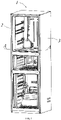
- the present invention relates to a refrigerating apparatus. As shown in FIG. 1 , a detailed explanation is mainly made by taking a refrigerator as an example. Certainly, the refrigerating apparatus may be a freezer or the like.
- the refrigerating apparatus includes a cabinet 1, wherein the cabinet 1 is provided with an inner liner 2 and a housing 3 between which a foaming cavity 4 is formed.
- a heat preservation layer (not shown) is usually formed by filling the foaming cavity 4 with a foaming material.
- the cabinet 1 is further provided with a flow-limiting plate 5 fixedly disposed between the housing 3 and the inn container 2 to limit the flow direction of the filled foaming material.
- the inner liner 2 of the cabinet 1 is provided with a refrigerating inner liner 21 and a freezing inner liner 22 located below the refrigerating inner liner 21.
- the inner liner 2 is further provided with a temperature-changing chamber inner liner 23 located between the refrigerating inner liner 21 and the freezing inner liner 22.
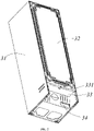
- the housing 3 is provided with a U-shell 31 covering two sides and the top of the inner liner 2, a rear shell 32 covering the rear side of the inner liner 2, and bottom steel 33 connected between the rear shell 32 and the lower side of the U-shell 31.
- the bottom steel 33 is Z-shaped so that a compressor chamber 34 for receiving a compressor (not shown) is also formed below the bottom steel 33 and between the U-shell 31 and the rear shell 32.
- the foaming cavity 4 is formed among the refrigerating inner liner 21, the freezing inner liner 22, the temperature-changing chamber inner liner 23, the U-shell 31, the rear shell 32 and the bottom steel 33, and is designed to be through from bottom to top.
- the depth of the foaming cavity 4 around the freezing inner liner 22 in the direction perpendicular to the housing 3 is greater than the depth of the foaming cavity 4 around the refrigerating inner liner 21 in the direction perpendicular to the housing 3.
- a filling port 331 communicated with the foaming cavity 4 is formed at the bottom of the housing 3, i.e., on the bottom steel 33 in this embodiment.
- the flow-limiting plate 5 is selectively secured to the inner liner 2 or the housing 3 according to the placement condition of the cabinet 1 in a foaming mould (not shown), and in order to avoid a heat bridge effect and ensure sufficient filling of the foaming material on the side of the flow-limiting plate 5 distal from the filling port 331, two ends of the flow-limiting plate 5 in the direction perpendicular to the housing 3 will not be simultaneously in contact with the inner liner 2 and the housing 3, i.e., the width of the flow-limiting plate 5 is smaller than the distance between the inner liner 2 and the housing 3 in the direction perpendicular to the housing 3.
- foaming of the cabinet 1 is executed after the rear shell 32 is placed downward, so that the flow-limiting plate 5 is fixedly disposed on the housing 3, specifically on the rear shell 32.
- the flow-limiting plate 5 is provided with a flow-limiting portion 51 perpendicular to the rear shell 32, and a gap is formed between the flow-limiting portion 51 and the inner liner 2.
- the width of the flow-limiting portion 51 in the direction perpendicular to the rear shell 32 is not more than half of the distance between the rear shell 32 and the inner liner 2 in the position where the flow-limiting portion 51 is located, so that the foaming material can flow in a conventional direction and can be partially limited. Therefore, the flow direction of the foaming material injected into the foaming cavity 4 through the filling port 331 is limited, and the foaming material is prevented from excessively moving toward the top wall of the cabinet 1 after the foaming material enters from the filling port 331.
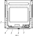
- the number of the flow-limiting plates 5 is two, and the two flow-limiting plates are located on the lower side behind the refrigerating inner liner 21, and extend in an arc shape from the middle to two sides.
- a motion space for the foaming material to move in the direction of the flow-limiting plate 5 distal from the filling port 331 is formed between the two flow-limiting plates 5 and between the flow-limiting plate 5 and the inner liner 2.
- the flow-limiting plate 5 can limit the flow rate of the foaming material moving in the direction distal from the filling port 331, and meanwhile, guide the foaming material to the inside of the foaming cavity 4 on two sides of the inner liner 2.
- the foaming material can be prevented from moving linearly and excessively flowing to the top of the cabinet 1 when a foaming gun performs foaming from the filling port 331, such that the foaming cavity 4 behind the refrigerating inner liner 22 demanding a great amount of the foaming material is sufficiently filled.
- the foaming cavity that is harder to fill on the two sides of the refrigerating inner liner 21 can be fully filled with the foaming material through a smaller gap, such that foaming voids or nonuniform foaming is avoided.
- the refrigerating apparatus has the better heat preservation property.
- two flow-limiting plates 5' are also provided, but the extending modes of the flow-limiting plates 5' differ from the extending mode in the previous embodiment in that the flow-limiting plates 5' extend obliquely from bottom to top and from inside to outside.
- the distance between the lower ends of the two flow-limiting plates 5' in the height direction of the rear shell 32' is smaller than the distance between the upper ends of the flow-limiting plates 5', such that the two flow-limiting plates 5' are substantially disposed in an inverted splayed shape with an upward opening.
- the two flow-limiting plates 5' are simultaneously arranged close to the bottom steel 33 or the filling port 331, such that the flow direction of the foaming material injected from the filling port 331 can be limited as soon as possible to facilitate rapid filling of the foaming material in each position of the foaming cavity. Therefore, the filling efficiency and the filling effect are improved.
- the motion space for the foaming material to pass through between the two flow-limiting plates 5, 5' is aligned with the filling port 331.
- the arrangement of the flow-limiting plates 5, 5' may also be correspondingly adjusted.
- the flow-limiting plate 5, 5' are fixedly disposed on the housing 3.
- the flow-limiting plate 5 is integrated with a fixing portion 52 connected to the flow-limiting portion 51, and the fixing portion 52 is perpendicularly connected to the flow-limiting portion 51, and secured to the rear shell 32 by bonding.
- the housing 1 is further provided with a fixture 6 by which the flow-limiting plate 5' is fixedly connected to the housing 3 or the inner liner 2.
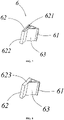
- the fixture 6 is provided with a fixing portion 61 secured to the rear shell 32 in a bonded manner, and a mounting portion 62 perpendicularly connected to the fixing portion 61, and the mounting portion 62 is provided with a mounting groove 621 matched with an end portion of the flow-limiting plate 5'.
- the mounting portion 62 is provided with a limiting wall 622 that limits the movement of the flow-limiting plate 5' towards the inner liner 2, and a blocking wall 623 that limits the movement of the flow-limiting plate 5' in its length direction.
- the fixture 6 is further provided with a reinforcing portion 63, which extends obliquely and is connected between the fixing portion 61 and the mounting portion 62.
- the flow-limiting plates 5, 5' in the present invention are made from a material having a melting point higher than the melting point of the foaming material, avoiding loss of a flow-limiting function due to direct melting at an excessively high temperature during filling of the foaming material.
- the flow-limiting plates 5, 5' may also be made from a material having a melting point approximate to the melting point of the foaming material, such that the flow-limiting plates can be melted into the foaming material after flow limiting is achieved, further reducing the risk of a heat bridge effect.
- the flow-limiting plates 5, 5' capable of limiting the flow direction of the filled foaming material are fixedly disposed in the foaming cavity 4 to limit the positions where the foaming material is accumulated a lot, such that the foaming material can flow to the positions prone to foaming voids or nonuniform foaming, and the effect of uniform foaming can be achieved without changing the structure of the filling port 331.
- the refrigerating apparatus provided by the present invention has the better heat preservation property.
Landscapes
- Engineering & Computer Science (AREA)
- Chemical & Material Sciences (AREA)
- Combustion & Propulsion (AREA)
- Physics & Mathematics (AREA)
- Mechanical Engineering (AREA)
- Thermal Sciences (AREA)
- General Engineering & Computer Science (AREA)
- Refrigerator Housings (AREA)
Abstract
Description
- The present invention relates to the field of refrigerating devices, and particularly relates to a refrigerating apparatus of which a heat preservation layer has a better filling effect.
- A refrigerator or a freezer, as a household appliance for freshness preservation, refrigeration or freezing of food, is owned by almost every household. A conventional refrigerator generally has a refrigerating compartment and a freezing compartment. In order to meet the heat preservation requirements for different temperatures in the two compartments and ensure that the two compartments are not influenced by the external ambient temperature, a heat preservation material is usually disposed in a cabinet of the refrigerator. The common setting is that a foaming material is filled between a housing and an inner liner of the refrigerator, and a heat preservation layer is formed after the foaming material is cured.
- It is well known that the heat preservation requirement of the refrigerating compartment is higher than that of the refrigerating compartment. In order to satisfy both of the heat preservation requirement and the requirement for a high capacity, the conventional refrigerator is provided that the refrigerating compartment is slightly larger than the freezing compartment, and that the thickness of the heat preservation layer around the refrigerating compartment is slightly smaller than that of the heat preservation layer around the freezing compartment. Currently, a one-shot filling for bottom steel is basically selected as the filling mode of the refrigerator, and there are problems that the refrigerating compartment is located above the freezing compartment and that a foaming space around the refrigerating compartment is narrow, which often lead to problems of nonuniform foaming density, foaming voids and the like. Since the two sides of the freezer are higher, sidewall foaming is problematic.
- Therefore, it is necessary to provide a refrigerating apparatus that can solve the above problems.
- The present invention provides a refrigerating apparatus with uniform foaming and an excellent heat preservation effect.
- In order to fulfill the above-mentioned objective, the technical solutions provided by the present invention are described as below.
- A refrigerating apparatus, comprising a box body, wherein the box body is provided with an inner liner and a housing between which a foaming cavity is formed; a heat preservation layer is formed by filling the foaming cavity with a foaming material; the box body is further provided with a flow-limiting plate that is fixedly disposed between the housing and the inner liner to limit a flow direction of the filled foaming material; and a width of the flow-limiting plate is smaller than a distance between the inner liner and the housing in a direction perpendicular to the housing.
- Further, wherein the flow-limiting plate is fixedly disposed on the housing and has a flow-limiting portion perpendicular to the housing, and a gap is formed between the flow-limiting portion and the inner liner.
- Further, wherein the housing is provided with a rear shell; the flow-limiting plate is fixedly disposed on the rear shell; and a width of the flow-limiting portion in a direction perpendicular to the rear shell is not more than half of a distance between the rear shell and the inner liner in a position where the flow-limiting portion is located.
- Further, wherein the flow-limiting plate is further provided with a fixing portion connected to the flow-limiting portion, and the fixing portion is perpendicularly connected to the flow-limiting portion, and secured to the rear shell in a bonded manner.
- Further, wherein the box body is further provided with a fixture by which the flow-limiting plate and the housing or the inner liner are fixedly connected; the fixture is provided with a fixing portion secured to the rear shell in a bonded manner, and a mounting portion perpendicularly connected to the fixing portion; and the mounting portion is provided with a mounting groove matched with an end portion of the flow-limiting plate.
- Further, wherein the mounting portion is provided with a limiting wall that limits movement of the flow-limiting plate towards the inner liner.
- Further, wherein the fixture is further provided with a reinforcing portion, and the reinforcing portion extends obliquely and is connected between the fixing portion and the mounting portion.
- Further, wherein the flow-limiting plate is made from a material having a melting point higher than a melting point of the foaming material.
- Further, wherein the inner liner is provided with a refrigerating inner liner and a freezing inner liner located below the refrigerating inner liner; a filling port communicated with the foaming cavity is disposed at a bottom of the housing; the number of the flow-limiting plates is two, and the two flow-limiting plates obliquely extend from inside to outside and from bottom to top in an inverted splayed shape respectively; and lower ends of the flow-limiting plates are disposed close to the filling port.
- Further, wherein the inner liner is provided with a refrigerating inner liner and a freezing inner liner located below the refrigerating inner liner, a filling port communicated with the foaming cavity is disposed at a bottom of the housing; the number of the flow-limiting plates is two, and the two flow-limiting plates are located on a lower side behind the refrigerating inner liner; the two flow-limiting plates extend in an arc shape from middle to two sides; and a motion space for the foaming material to pass through is formed between the two flow-limiting plates.
- Compared with the prior art, the present invention has the following beneficial effects: the flow-limiting plate capable of limiting the flow direction of the filled foaming material is fixedly disposed between the housing and the inner liner of the cabinet to limit the positions where the foaming material is accumulated a lot, such that the foaming material can flow to the positions prone to foaming voids or nonuniform foaming, and the effect of uniform foaming can be achieved without changing the structure of the filling port. Therefore, the refrigerating apparatus provided by the present invention has a better heat preservation property.
-
-
FIG. 1 is a perspective view of a cabinet of a refrigerating apparatus according to the present invention; -
FIG. 2 is another view of the cabinet shown inFIG. 1 ; -
FIG. 3 is a partially exploded view of the cabinet shown inFIG. 1 ; -
FIG. 4 is a top view of the cabinet shown inFIG. 1 and exploded along line A-A ofFIG. 1 ; -
FIG. 5 is a perspective view of a rear shell and a flow-limiting plate of the cabinet according to another preferred embodiment of the present invention; -
FIG. 6 is a perspective exploded view of the rear shell and the flow-limiting plate shown inFIG. 5 ; -
FIG. 7 is a perspective view of a fixture for fixing the flow-limiting plate inFIG. 5 ; and -
FIG. 8 is another view of the fixture inFIG. 7 . - In order to make a person skilled in the art better understand the solutions of the present invention, the technical solutions in the embodiments of the present invention will be clearly and completely described below with reference to the accompanying drawings in the embodiments of the present invention. Obviously, the embodiments described are merely some but not all embodiments of the present invention. Based on the embodiments of the present invention, all other embodiments derived by a person of ordinary skill in the art without creative efforts shall fall within the protection scope of the present invention.
- The present invention relates to a refrigerating apparatus. As shown in
FIG. 1 , a detailed explanation is mainly made by taking a refrigerator as an example. Certainly, the refrigerating apparatus may be a freezer or the like. - Referring to
FIGs. 1 to 4 , the refrigerating apparatus provided by the present invention includes a cabinet 1, wherein the cabinet 1 is provided with aninner liner 2 and ahousing 3 between which afoaming cavity 4 is formed. A heat preservation layer (not shown) is usually formed by filling thefoaming cavity 4 with a foaming material. In the present invention, the cabinet 1 is further provided with a flow-limitingplate 5 fixedly disposed between thehousing 3 and theinn container 2 to limit the flow direction of the filled foaming material. - Specifically, as shown in
FIGs. 1 and2 , theinner liner 2 of the cabinet 1 is provided with a refrigeratinginner liner 21 and a freezinginner liner 22 located below the refrigeratinginner liner 21. In this embodiment, theinner liner 2 is further provided with a temperature-changing chamberinner liner 23 located between the refrigeratinginner liner 21 and the freezinginner liner 22. - The
housing 3 is provided with aU-shell 31 covering two sides and the top of theinner liner 2, arear shell 32 covering the rear side of theinner liner 2, andbottom steel 33 connected between therear shell 32 and the lower side of the U-shell 31. Thebottom steel 33 is Z-shaped so that acompressor chamber 34 for receiving a compressor (not shown) is also formed below thebottom steel 33 and between theU-shell 31 and therear shell 32. - The
foaming cavity 4 is formed among the refrigeratinginner liner 21, the freezinginner liner 22, the temperature-changing chamberinner liner 23, theU-shell 31, therear shell 32 and thebottom steel 33, and is designed to be through from bottom to top. The depth of thefoaming cavity 4 around the freezinginner liner 22 in the direction perpendicular to thehousing 3 is greater than the depth of thefoaming cavity 4 around the refrigeratinginner liner 21 in the direction perpendicular to thehousing 3. - A
filling port 331 communicated with thefoaming cavity 4 is formed at the bottom of thehousing 3, i.e., on thebottom steel 33 in this embodiment. - The flow-
limiting plate 5 is selectively secured to theinner liner 2 or thehousing 3 according to the placement condition of the cabinet 1 in a foaming mould (not shown), and in order to avoid a heat bridge effect and ensure sufficient filling of the foaming material on the side of the flow-limitingplate 5 distal from thefilling port 331, two ends of the flow-limiting plate 5 in the direction perpendicular to thehousing 3 will not be simultaneously in contact with theinner liner 2 and thehousing 3, i.e., the width of the flow-limiting plate 5 is smaller than the distance between theinner liner 2 and thehousing 3 in the direction perpendicular to thehousing 3. - In a preferred embodiment of the present invention, foaming of the cabinet 1 is executed after the
rear shell 32 is placed downward, so that the flow-limitingplate 5 is fixedly disposed on thehousing 3, specifically on therear shell 32. The flow-limitingplate 5 is provided with a flow-limitingportion 51 perpendicular to therear shell 32, and a gap is formed between the flow-limitingportion 51 and theinner liner 2. - Preferably, the width of the flow-limiting
portion 51 in the direction perpendicular to therear shell 32 is not more than half of the distance between therear shell 32 and theinner liner 2 in the position where the flow-limitingportion 51 is located, so that the foaming material can flow in a conventional direction and can be partially limited. Therefore, the flow direction of the foaming material injected into thefoaming cavity 4 through thefilling port 331 is limited, and the foaming material is prevented from excessively moving toward the top wall of the cabinet 1 after the foaming material enters from thefilling port 331. - As shown in
FIGs. 3 and4 , as a preferred embodiment of the present invention, the number of the flow-limitingplates 5 is two, and the two flow-limiting plates are located on the lower side behind the refrigeratinginner liner 21, and extend in an arc shape from the middle to two sides. A motion space for the foaming material to move in the direction of the flow-limitingplate 5 distal from thefilling port 331 is formed between the two flow-limiting plates 5 and between the flow-limitingplate 5 and theinner liner 2. The flow-limiting plate 5 can limit the flow rate of the foaming material moving in the direction distal from thefilling port 331, and meanwhile, guide the foaming material to the inside of thefoaming cavity 4 on two sides of theinner liner 2. - Since the distance between the refrigerating
inner liner 21 and thehousing 3 is relatively small, on the one hand, the foaming material can be prevented from moving linearly and excessively flowing to the top of the cabinet 1 when a foaming gun performs foaming from thefilling port 331, such that thefoaming cavity 4 behind the refrigeratinginner liner 22 demanding a great amount of the foaming material is sufficiently filled. On the other hand, the foaming cavity that is harder to fill on the two sides of the refrigeratinginner liner 21 can be fully filled with the foaming material through a smaller gap, such that foaming voids or nonuniform foaming is avoided. Further, the refrigerating apparatus has the better heat preservation property. - As another preferred embodiment of the present invention, referring to
FIGs. 5 and6 , in this embodiment, two flow-limiting plates 5' are also provided, but the extending modes of the flow-limiting plates 5' differ from the extending mode in the previous embodiment in that the flow-limiting plates 5' extend obliquely from bottom to top and from inside to outside. The distance between the lower ends of the two flow-limiting plates 5' in the height direction of the rear shell 32' is smaller than the distance between the upper ends of the flow-limiting plates 5', such that the two flow-limiting plates 5' are substantially disposed in an inverted splayed shape with an upward opening. - In addition, in the embodiment, the two flow-limiting plates 5' are simultaneously arranged close to the
bottom steel 33 or the fillingport 331, such that the flow direction of the foaming material injected from the fillingport 331 can be limited as soon as possible to facilitate rapid filling of the foaming material in each position of the foaming cavity. Therefore, the filling efficiency and the filling effect are improved. - Based on the symmetrical arrangement of the conventional refrigerating apparatus in the width direction, in the preferred embodiment of the present invention, the motion space for the foaming material to pass through between the two flow-limiting
plates 5, 5' is aligned with the fillingport 331. Certainly, when an air passage and other structures are disposed between theinner liner 2 and thehousing 3 to cause thefoaming cavity 4 to be asymmetrical in structure, the arrangement of the flow-limitingplates 5, 5' may also be correspondingly adjusted. - As stated above, according to the present invention, the flow-limiting
plate 5, 5' are fixedly disposed on thehousing 3. As a preferred embodiment of the present invention, as shown inFIG. 3 , the flow-limitingplate 5 is integrated with a fixingportion 52 connected to the flow-limitingportion 51, and the fixingportion 52 is perpendicularly connected to the flow-limitingportion 51, and secured to therear shell 32 by bonding. - As another preferred embodiment of the present invention, as shown in
FIGs. 5 to 8 , the housing 1 is further provided with afixture 6 by which the flow-limiting plate 5' is fixedly connected to thehousing 3 or theinner liner 2. - The
fixture 6 is provided with a fixingportion 61 secured to therear shell 32 in a bonded manner, and a mountingportion 62 perpendicularly connected to the fixingportion 61, and the mountingportion 62 is provided with a mountinggroove 621 matched with an end portion of the flow-limiting plate 5'. - Preferably, the mounting
portion 62 is provided with a limitingwall 622 that limits the movement of the flow-limiting plate 5' towards theinner liner 2, and a blockingwall 623 that limits the movement of the flow-limiting plate 5' in its length direction. In order to enhance the strength of thefixture 6, thefixture 6 is further provided with a reinforcingportion 63, which extends obliquely and is connected between the fixingportion 61 and the mountingportion 62. - Further, the flow-limiting
plates 5, 5' in the present invention are made from a material having a melting point higher than the melting point of the foaming material, avoiding loss of a flow-limiting function due to direct melting at an excessively high temperature during filling of the foaming material. Certainly, the flow-limitingplates 5, 5' may also be made from a material having a melting point approximate to the melting point of the foaming material, such that the flow-limiting plates can be melted into the foaming material after flow limiting is achieved, further reducing the risk of a heat bridge effect. - In summary, in the present invention, the flow-limiting
plates 5, 5' capable of limiting the flow direction of the filled foaming material are fixedly disposed in the foamingcavity 4 to limit the positions where the foaming material is accumulated a lot, such that the foaming material can flow to the positions prone to foaming voids or nonuniform foaming, and the effect of uniform foaming can be achieved without changing the structure of the fillingport 331. Further, the refrigerating apparatus provided by the present invention has the better heat preservation property. - It should be understood that although the description is described based on the embodiments, not every embodiment includes only one independent technical solution. This statement of the description is only for clarity. Those skilled in the art should treat the description as a whole, and technical solutions in all of the embodiments may also be properly combined to form other embodiments that will be understood by those skilled in the art.
- The above detailed description only aims to specifically illustrate the available embodiments of the present invention, and is not intended to limit the protection scope of the present invention. Equivalent embodiments or modifications made without departing from the spirit of the present invention shall fall within the protection scope of the present invention.
Claims (10)
- A refrigerating apparatus, comprising a cabinet (1), wherein the cabinet (1) is provided with an inner liner (21) and a housing (3) between which a foaming cavity (4) is formed; a heat preservation layer is formed by filling the foaming cavity (4) with a foaming material; the cabinet (1) is further provided with a flow-limiting plate (5) that is fixedly disposed between the housing (3) and the inner liner (21) to limit a flow direction of the filled foaming material; and a width of the flow-limiting plate (5) is smaller than a distance between the inner liner (21) and the housing (3) in a direction perpendicular to the housing (3).
- The refrigerating apparatus according to claim 1, wherein the flow-limiting plate (5) is fixedly disposed on the housing (3) and has a flow-limiting portion (51) perpendicular to the housing (3), and a gap is formed between the flow-limiting portion (51) and the inner liner (21).
- The refrigerating apparatus according to claim 2, wherein the housing (3) is provided with a rear shell (32); the flow-limiting plate (5) is fixedly disposed on the rear shell (32); and a width of the flow-limiting portion (51) in a direction perpendicular to the rear shell (32) is not more than half of a distance between the rear shell (32) and the inner liner (21) in a position where the flow-limiting portion (51) is located.
- The refrigerating apparatus according to claim 3, wherein the flow-limiting plate (5) is further provided with a fixing portion (52) connected to the flow-limiting portion (51), and the fixing portion (52) is perpendicularly connected to the flow-limiting portion (51), and secured to the rear shell (32) in a bonded manner.
- The refrigerating apparatus according to claim 3, wherein the cabinet (1) is further provided with a fixture (6) by which the flow-limiting plate (5) and the housing (3) or the inner liner (21) are fixedly connected; the fixture (6) is provided with a fixing portion (52) secured to the rear shell (32) in a bonded manner, and a mounting portion (62) perpendicularly connected to the fixing portion (52); and the mounting portion (62) is provided with a mounting groove (621) matched with an end portion of the flow-limiting plate (5).
- The refrigerating apparatus according to claim 5, wherein the mounting portion (62) is provided with a limiting wall (622) that limits movement of the flow-limiting plate (5) towards the inner liner (21).
- The refrigerating apparatus according to claim 5, wherein the fixture (6) is further provided with a reinforcing portion (63), and the reinforcing portion (63) extends obliquely and is connected between the fixing portion (52) and the mounting portion (62).
- The refrigerating apparatus according to claim 1, wherein the flow-limiting plate (5) is made from a material having a melting point higher than a melting point of the foaming material.
- The refrigerating apparatus according to claim 1, wherein the inner liner (21) is provided with a refrigerating inner liner (21) and a freezing inner liner (21) located below the refrigerating inner liner (21); a filling port (331) communicated with the foaming cavity (4) is disposed at a bottom of the housing (3); the number of the flow-limiting plates (5) is two, and the two flow-limiting plates (5) obliquely extend from inside to outside and from bottom to top in an inverted splayed shape respectively; and lower ends of the flow-limiting plates (5) are disposed close to the filling port (331).
- The refrigerating apparatus according to claim 1, wherein the inner liner (21) is provided with a refrigerating inner liner (21) and a freezing inner liner (21) located below the refrigerating inner liner (21), a filling port (331) communicated with the foaming cavity (4) is disposed at a bottom of the housing (3); the number of the flow-limiting plates (5) is two, and the two flow-limiting plates (5) are located on a lower side behind the refrigerating inner liner (21); the two flow-limiting plates (5) extend in an arc shape from middle to two sides; and a motion space for the foaming material to pass through is formed between the two flow-limiting plates (5).
Applications Claiming Priority (2)
| Application Number | Priority Date | Filing Date | Title |
|---|---|---|---|
| CN201911171335.9A CN112856894A (en) | 2019-11-26 | 2019-11-26 | Refrigerating device |
| PCT/CN2020/131078 WO2021104243A1 (en) | 2019-11-26 | 2020-11-24 | Refrigeration device |
Publications (3)
| Publication Number | Publication Date |
|---|---|
| EP4067782A1 true EP4067782A1 (en) | 2022-10-05 |
| EP4067782A4 EP4067782A4 (en) | 2022-12-28 |
| EP4067782B1 EP4067782B1 (en) | 2025-04-02 |
Family
ID=75984706
Family Applications (1)
| Application Number | Title | Priority Date | Filing Date |
|---|---|---|---|
| EP20894651.7A Active EP4067782B1 (en) | 2019-11-26 | 2020-11-24 | Refrigerating apparatus |
Country Status (3)
| Country | Link |
|---|---|
| EP (1) | EP4067782B1 (en) |
| CN (1) | CN112856894A (en) |
| WO (1) | WO2021104243A1 (en) |
Family Cites Families (25)
| Publication number | Priority date | Publication date | Assignee | Title |
|---|---|---|---|---|
| JPS50156467U (en) * | 1974-06-13 | 1975-12-25 | ||
| JPS62200179A (en) * | 1986-02-28 | 1987-09-03 | 株式会社日立製作所 | insulation box body |
| JP2562077Y2 (en) * | 1993-02-23 | 1998-02-04 | ホシザキ電機株式会社 | Insulated box |
| JPH10259987A (en) * | 1997-03-19 | 1998-09-29 | Toshiba Corp | Insulation structure |
| DE19728648A1 (en) * | 1997-07-04 | 1999-01-07 | Aeg Hausgeraete Gmbh | Cooling and/or freezing unit |
| JPH11132646A (en) * | 1997-10-31 | 1999-05-21 | Sanyo Electric Co Ltd | refrigerator |
| US6109712A (en) * | 1998-07-16 | 2000-08-29 | Maytag Corporation | Integrated vacuum panel insulation for thermal cabinet structures |
| JP4013461B2 (en) * | 2000-08-07 | 2007-11-28 | いすゞ自動車株式会社 | Thermal insulation panel |
| JP2003065669A (en) * | 2001-08-28 | 2003-03-05 | Hitachi Ltd | refrigerator |
| JP2010276310A (en) * | 2009-05-29 | 2010-12-09 | Hitachi Appliances Inc | Refrigerator with vacuum insulation |
| JP2011089670A (en) * | 2009-10-21 | 2011-05-06 | Panasonic Corp | Method of manufacturing heat insulating housing and refrigerator |
| CN201950762U (en) * | 2010-11-30 | 2011-08-31 | 海尔集团公司 | Foam deflector for refrigerator door and refrigerator with same |
| CN102287997B (en) * | 2011-08-18 | 2016-07-06 | 海尔集团公司 | The support member of refrigerator compressor warehouse and have compressor bin and the refrigerator of this support member |
| US20140015395A1 (en) * | 2012-07-12 | 2014-01-16 | Whirlpool Corporation | Refrigerator with platform for improved foam discharge |
| CN102901303B (en) * | 2012-09-17 | 2015-04-15 | 合肥华凌股份有限公司 | Refrigerator |
| CN202885416U (en) * | 2012-10-23 | 2013-04-17 | 合肥美的荣事达电冰箱有限公司 | Refrigerator |
| JP6021064B2 (en) * | 2013-01-10 | 2016-11-02 | パナソニックIpマネジメント株式会社 | Insulating panel and method for manufacturing the same |
| KR20150010846A (en) * | 2013-07-18 | 2015-01-29 | 삼성전자주식회사 | Refrigerator |
| CN204126058U (en) * | 2014-10-16 | 2015-01-28 | 张瑞龙 | Chute baffle plate bracing frame |
| CN105222491A (en) * | 2015-09-18 | 2016-01-06 | 合肥华凌股份有限公司 | Refrigerator |
| KR102442071B1 (en) * | 2015-10-19 | 2022-09-13 | 삼성전자주식회사 | Refrigerator and its manufacturing method |
| CN106382779B (en) * | 2016-10-08 | 2019-11-05 | Tcl家用电器(合肥)有限公司 | Display control unit and refrigerator |
| CN209243949U (en) * | 2018-11-30 | 2019-08-13 | 太仓安博工业科技有限公司 | Two hole slot type angle connectors |
| CN109968580A (en) * | 2019-03-28 | 2019-07-05 | 合肥华凌股份有限公司 | Refrigeration equipment and its production method |
| CN211372889U (en) * | 2019-11-26 | 2020-08-28 | 青岛海尔电冰箱有限公司 | refrigeration unit |
-
2019
- 2019-11-26 CN CN201911171335.9A patent/CN112856894A/en active Pending
-
2020
- 2020-11-24 EP EP20894651.7A patent/EP4067782B1/en active Active
- 2020-11-24 WO PCT/CN2020/131078 patent/WO2021104243A1/en not_active Ceased
Also Published As
| Publication number | Publication date |
|---|---|
| CN112856894A (en) | 2021-05-28 |
| EP4067782B1 (en) | 2025-04-02 |
| EP4067782A4 (en) | 2022-12-28 |
| WO2021104243A1 (en) | 2021-06-03 |
Similar Documents
| Publication | Publication Date | Title |
|---|---|---|
| CN201811526U (en) | Refrigerator | |
| EP3023717A1 (en) | Refrigerator | |
| CN102692110B (en) | Refrigerator | |
| KR102721119B1 (en) | Refrigerator | |
| CN204043281U (en) | Refrigerator | |
| CN110440504A (en) | a refrigerator | |
| JP4218742B1 (en) | refrigerator | |
| CN111981750B (en) | Refrigerator and method of manufacturing the same | |
| JP6448984B2 (en) | refrigerator | |
| KR20240115208A (en) | Refrigerator | |
| EP4067782B1 (en) | Refrigerating apparatus | |
| CN112303994A (en) | Cold storage | |
| JP5625551B2 (en) | refrigerator | |
| KR20190030295A (en) | Refrigerator | |
| CN110440503A (en) | A kind of refrigerator | |
| CN211372889U (en) | refrigeration unit | |
| KR101260559B1 (en) | Refrigerator | |
| KR102891179B1 (en) | Refrigerator | |
| ES2275760T3 (en) | A HOUSING THERMALLY ISOLATED FOR A REFRIGERATORY DEVICE. | |
| CN107810374A (en) | Refrigerator | |
| US11561039B2 (en) | Sealing assembly having improved heat insulation properties and cooling device having the sealing assembly | |
| CN110440513A (en) | A kind of refrigerator | |
| JP2019032161A (en) | refrigerator | |
| WO2024021619A1 (en) | Refrigeration device | |
| KR100751106B1 (en) | Cold room door with ice tray |
Legal Events
| Date | Code | Title | Description |
|---|---|---|---|
| STAA | Information on the status of an ep patent application or granted ep patent |
Free format text: STATUS: THE INTERNATIONAL PUBLICATION HAS BEEN MADE |
|
| PUAI | Public reference made under article 153(3) epc to a published international application that has entered the european phase |
Free format text: ORIGINAL CODE: 0009012 |
|
| STAA | Information on the status of an ep patent application or granted ep patent |
Free format text: STATUS: REQUEST FOR EXAMINATION WAS MADE |
|
| 17P | Request for examination filed |
Effective date: 20220331 |
|
| AK | Designated contracting states |
Kind code of ref document: A1 Designated state(s): AL AT BE BG CH CY CZ DE DK EE ES FI FR GB GR HR HU IE IS IT LI LT LU LV MC MK MT NL NO PL PT RO RS SE SI SK SM TR |
|
| REG | Reference to a national code |
Ref country code: DE Free format text: PREVIOUS MAIN CLASS: F25D0011020000 Ref country code: DE Ref legal event code: R079 Ref document number: 602020048906 Country of ref document: DE Free format text: PREVIOUS MAIN CLASS: F25D0011020000 Ipc: F25D0023060000 |
|
| A4 | Supplementary search report drawn up and despatched |
Effective date: 20221125 |
|
| RIC1 | Information provided on ipc code assigned before grant |
Ipc: F25D 23/06 20060101AFI20221121BHEP |
|
| DAV | Request for validation of the european patent (deleted) | ||
| DAX | Request for extension of the european patent (deleted) | ||
| GRAP | Despatch of communication of intention to grant a patent |
Free format text: ORIGINAL CODE: EPIDOSNIGR1 |
|
| STAA | Information on the status of an ep patent application or granted ep patent |
Free format text: STATUS: GRANT OF PATENT IS INTENDED |
|
| INTG | Intention to grant announced |
Effective date: 20241104 |
|
| GRAS | Grant fee paid |
Free format text: ORIGINAL CODE: EPIDOSNIGR3 |
|
| GRAA | (expected) grant |
Free format text: ORIGINAL CODE: 0009210 |
|
| STAA | Information on the status of an ep patent application or granted ep patent |
Free format text: STATUS: THE PATENT HAS BEEN GRANTED |
|
| AK | Designated contracting states |
Kind code of ref document: B1 Designated state(s): AL AT BE BG CH CY CZ DE DK EE ES FI FR GB GR HR HU IE IS IT LI LT LU LV MC MK MT NL NO PL PT RO RS SE SI SK SM TR |
|
| RAP3 | Party data changed (applicant data changed or rights of an application transferred) |
Owner name: HAIER SMART HOME CO., LTD. Owner name: QINGDAO HAIER REFRIGERATOR CO., LTD |
|
| REG | Reference to a national code |
Ref country code: GB Ref legal event code: FG4D |
|
| REG | Reference to a national code |
Ref country code: CH Ref legal event code: EP |
|
| REG | Reference to a national code |
Ref country code: IE Ref legal event code: FG4D |
|
| REG | Reference to a national code |
Ref country code: DE Ref legal event code: R096 Ref document number: 602020048906 Country of ref document: DE |
|
| REG | Reference to a national code |
Ref country code: NL Ref legal event code: MP Effective date: 20250402 |
|
| PG25 | Lapsed in a contracting state [announced via postgrant information from national office to epo] |
Ref country code: NL Free format text: LAPSE BECAUSE OF FAILURE TO SUBMIT A TRANSLATION OF THE DESCRIPTION OR TO PAY THE FEE WITHIN THE PRESCRIBED TIME-LIMIT Effective date: 20250402 |
|
| REG | Reference to a national code |
Ref country code: AT Ref legal event code: MK05 Ref document number: 1781621 Country of ref document: AT Kind code of ref document: T Effective date: 20250402 |
|
| PG25 | Lapsed in a contracting state [announced via postgrant information from national office to epo] |
Ref country code: FI Free format text: LAPSE BECAUSE OF FAILURE TO SUBMIT A TRANSLATION OF THE DESCRIPTION OR TO PAY THE FEE WITHIN THE PRESCRIBED TIME-LIMIT Effective date: 20250402 Ref country code: ES Free format text: LAPSE BECAUSE OF FAILURE TO SUBMIT A TRANSLATION OF THE DESCRIPTION OR TO PAY THE FEE WITHIN THE PRESCRIBED TIME-LIMIT Effective date: 20250402 Ref country code: PT Free format text: LAPSE BECAUSE OF FAILURE TO SUBMIT A TRANSLATION OF THE DESCRIPTION OR TO PAY THE FEE WITHIN THE PRESCRIBED TIME-LIMIT Effective date: 20250804 |
|
| REG | Reference to a national code |
Ref country code: LT Ref legal event code: MG9D |
|
| PG25 | Lapsed in a contracting state [announced via postgrant information from national office to epo] |
Ref country code: NO Free format text: LAPSE BECAUSE OF FAILURE TO SUBMIT A TRANSLATION OF THE DESCRIPTION OR TO PAY THE FEE WITHIN THE PRESCRIBED TIME-LIMIT Effective date: 20250702 Ref country code: GR Free format text: LAPSE BECAUSE OF FAILURE TO SUBMIT A TRANSLATION OF THE DESCRIPTION OR TO PAY THE FEE WITHIN THE PRESCRIBED TIME-LIMIT Effective date: 20250703 |
|
| PG25 | Lapsed in a contracting state [announced via postgrant information from national office to epo] |
Ref country code: PL Free format text: LAPSE BECAUSE OF FAILURE TO SUBMIT A TRANSLATION OF THE DESCRIPTION OR TO PAY THE FEE WITHIN THE PRESCRIBED TIME-LIMIT Effective date: 20250402 |
|
| PG25 | Lapsed in a contracting state [announced via postgrant information from national office to epo] |
Ref country code: BG Free format text: LAPSE BECAUSE OF FAILURE TO SUBMIT A TRANSLATION OF THE DESCRIPTION OR TO PAY THE FEE WITHIN THE PRESCRIBED TIME-LIMIT Effective date: 20250402 |
|
| PG25 | Lapsed in a contracting state [announced via postgrant information from national office to epo] |
Ref country code: HR Free format text: LAPSE BECAUSE OF FAILURE TO SUBMIT A TRANSLATION OF THE DESCRIPTION OR TO PAY THE FEE WITHIN THE PRESCRIBED TIME-LIMIT Effective date: 20250402 |
|
| PG25 | Lapsed in a contracting state [announced via postgrant information from national office to epo] |
Ref country code: AT Free format text: LAPSE BECAUSE OF FAILURE TO SUBMIT A TRANSLATION OF THE DESCRIPTION OR TO PAY THE FEE WITHIN THE PRESCRIBED TIME-LIMIT Effective date: 20250402 |
|
| PG25 | Lapsed in a contracting state [announced via postgrant information from national office to epo] |
Ref country code: RS Free format text: LAPSE BECAUSE OF FAILURE TO SUBMIT A TRANSLATION OF THE DESCRIPTION OR TO PAY THE FEE WITHIN THE PRESCRIBED TIME-LIMIT Effective date: 20250702 |
|
| PG25 | Lapsed in a contracting state [announced via postgrant information from national office to epo] |
Ref country code: IS Free format text: LAPSE BECAUSE OF FAILURE TO SUBMIT A TRANSLATION OF THE DESCRIPTION OR TO PAY THE FEE WITHIN THE PRESCRIBED TIME-LIMIT Effective date: 20250802 |
|
| PG25 | Lapsed in a contracting state [announced via postgrant information from national office to epo] |
Ref country code: LV Free format text: LAPSE BECAUSE OF FAILURE TO SUBMIT A TRANSLATION OF THE DESCRIPTION OR TO PAY THE FEE WITHIN THE PRESCRIBED TIME-LIMIT Effective date: 20250402 |
|
| REG | Reference to a national code |
Ref country code: DE Ref legal event code: R097 Ref document number: 602020048906 Country of ref document: DE |
|
| PGFP | Annual fee paid to national office [announced via postgrant information from national office to epo] |
Ref country code: DE Payment date: 20251117 Year of fee payment: 6 |
|
| PGFP | Annual fee paid to national office [announced via postgrant information from national office to epo] |
Ref country code: GB Payment date: 20251126 Year of fee payment: 6 |
|
| PG25 | Lapsed in a contracting state [announced via postgrant information from national office to epo] |
Ref country code: SM Free format text: LAPSE BECAUSE OF FAILURE TO SUBMIT A TRANSLATION OF THE DESCRIPTION OR TO PAY THE FEE WITHIN THE PRESCRIBED TIME-LIMIT Effective date: 20250402 Ref country code: DK Free format text: LAPSE BECAUSE OF FAILURE TO SUBMIT A TRANSLATION OF THE DESCRIPTION OR TO PAY THE FEE WITHIN THE PRESCRIBED TIME-LIMIT Effective date: 20250402 |
|
| PG25 | Lapsed in a contracting state [announced via postgrant information from national office to epo] |
Ref country code: CZ Free format text: LAPSE BECAUSE OF FAILURE TO SUBMIT A TRANSLATION OF THE DESCRIPTION OR TO PAY THE FEE WITHIN THE PRESCRIBED TIME-LIMIT Effective date: 20250402 |
|
| PG25 | Lapsed in a contracting state [announced via postgrant information from national office to epo] |
Ref country code: EE Free format text: LAPSE BECAUSE OF FAILURE TO SUBMIT A TRANSLATION OF THE DESCRIPTION OR TO PAY THE FEE WITHIN THE PRESCRIBED TIME-LIMIT Effective date: 20250402 |
|
| PG25 | Lapsed in a contracting state [announced via postgrant information from national office to epo] |
Ref country code: SK Free format text: LAPSE BECAUSE OF FAILURE TO SUBMIT A TRANSLATION OF THE DESCRIPTION OR TO PAY THE FEE WITHIN THE PRESCRIBED TIME-LIMIT Effective date: 20250402 |
|
| PG25 | Lapsed in a contracting state [announced via postgrant information from national office to epo] |
Ref country code: IT Free format text: LAPSE BECAUSE OF FAILURE TO SUBMIT A TRANSLATION OF THE DESCRIPTION OR TO PAY THE FEE WITHIN THE PRESCRIBED TIME-LIMIT Effective date: 20250402 |
|
| PLBE | No opposition filed within time limit |
Free format text: ORIGINAL CODE: 0009261 |
|
| STAA | Information on the status of an ep patent application or granted ep patent |
Free format text: STATUS: NO OPPOSITION FILED WITHIN TIME LIMIT |
|
| PG25 | Lapsed in a contracting state [announced via postgrant information from national office to epo] |
Ref country code: RO Free format text: LAPSE BECAUSE OF FAILURE TO SUBMIT A TRANSLATION OF THE DESCRIPTION OR TO PAY THE FEE WITHIN THE PRESCRIBED TIME-LIMIT Effective date: 20250402 |
|
| REG | Reference to a national code |
Ref country code: CH Ref legal event code: L10 Free format text: ST27 STATUS EVENT CODE: U-0-0-L10-L00 (AS PROVIDED BY THE NATIONAL OFFICE) Effective date: 20260211 |
|
| 26N | No opposition filed |
Effective date: 20260105 |
|
| REG | Reference to a national code |
Ref country code: CH Ref legal event code: H13 Free format text: ST27 STATUS EVENT CODE: U-0-0-H10-H13 (AS PROVIDED BY THE NATIONAL OFFICE) Effective date: 20260623 |
|
| PG25 | Lapsed in a contracting state [announced via postgrant information from national office to epo] |
Ref country code: LT Free format text: LAPSE BECAUSE OF FAILURE TO SUBMIT A TRANSLATION OF THE DESCRIPTION OR TO PAY THE FEE WITHIN THE PRESCRIBED TIME-LIMIT Effective date: 20250402 |
|
| PG25 | Lapsed in a contracting state [announced via postgrant information from national office to epo] |
Ref country code: MC Free format text: LAPSE BECAUSE OF FAILURE TO SUBMIT A TRANSLATION OF THE DESCRIPTION OR TO PAY THE FEE WITHIN THE PRESCRIBED TIME-LIMIT Effective date: 20250402 |
|
| PG25 | Lapsed in a contracting state [announced via postgrant information from national office to epo] |
Ref country code: CH Free format text: LAPSE BECAUSE OF NON-PAYMENT OF DUE FEES Effective date: 20251130 Ref country code: LU Free format text: LAPSE BECAUSE OF NON-PAYMENT OF DUE FEES Effective date: 20251124 |
|
| PG25 | Lapsed in a contracting state [announced via postgrant information from national office to epo] |
Ref country code: SE Free format text: LAPSE BECAUSE OF FAILURE TO SUBMIT A TRANSLATION OF THE DESCRIPTION OR TO PAY THE FEE WITHIN THE PRESCRIBED TIME-LIMIT Effective date: 20250402 |