EP4067718B1 - Sealing device for bores of a heat exchanger - Google Patents
Sealing device for bores of a heat exchanger Download PDFInfo
- Publication number
- EP4067718B1 EP4067718B1 EP21425013.6A EP21425013A EP4067718B1 EP 4067718 B1 EP4067718 B1 EP 4067718B1 EP 21425013 A EP21425013 A EP 21425013A EP 4067718 B1 EP4067718 B1 EP 4067718B1
- Authority
- EP
- European Patent Office
- Prior art keywords
- gasket
- contact surface
- annular contact
- shank
- sealing device
- Prior art date
- Legal status (The legal status is an assumption and is not a legal conclusion. Google has not performed a legal analysis and makes no representation as to the accuracy of the status listed.)
- Active
Links
Images




Classifications
-
- F—MECHANICAL ENGINEERING; LIGHTING; HEATING; WEAPONS; BLASTING
- F28—HEAT EXCHANGE IN GENERAL
- F28F—DETAILS OF HEAT-EXCHANGE AND HEAT-TRANSFER APPARATUS, OF GENERAL APPLICATION
- F28F9/00—Casings; Header boxes; Auxiliary supports for elements; Auxiliary members within casings
- F28F9/02—Header boxes; End plates
-
- F—MECHANICAL ENGINEERING; LIGHTING; HEATING; WEAPONS; BLASTING
- F16—ENGINEERING ELEMENTS AND UNITS; GENERAL MEASURES FOR PRODUCING AND MAINTAINING EFFECTIVE FUNCTIONING OF MACHINES OR INSTALLATIONS; THERMAL INSULATION IN GENERAL
- F16B—DEVICES FOR FASTENING OR SECURING CONSTRUCTIONAL ELEMENTS OR MACHINE PARTS TOGETHER, e.g. NAILS, BOLTS, CIRCLIPS, CLAMPS, CLIPS OR WEDGES; JOINTS OR JOINTING
- F16B43/00—Washers or equivalent devices; Other devices for supporting bolt-heads or nuts
- F16B43/001—Washers or equivalent devices; Other devices for supporting bolt-heads or nuts for sealing or insulation
-
- F—MECHANICAL ENGINEERING; LIGHTING; HEATING; WEAPONS; BLASTING
- F16—ENGINEERING ELEMENTS AND UNITS; GENERAL MEASURES FOR PRODUCING AND MAINTAINING EFFECTIVE FUNCTIONING OF MACHINES OR INSTALLATIONS; THERMAL INSULATION IN GENERAL
- F16L—PIPES; JOINTS OR FITTINGS FOR PIPES; SUPPORTS FOR PIPES, CABLES OR PROTECTIVE TUBING; MEANS FOR THERMAL INSULATION IN GENERAL
- F16L55/00—Devices or appurtenances for use in, or in connection with, pipes or pipe systems
- F16L55/10—Means for stopping flow in pipes or hoses
- F16L55/11—Plugs
- F16L55/1108—Plugs fixed by screwing or by means of a screw-threaded ring
-
- F—MECHANICAL ENGINEERING; LIGHTING; HEATING; WEAPONS; BLASTING
- F28—HEAT EXCHANGE IN GENERAL
- F28F—DETAILS OF HEAT-EXCHANGE AND HEAT-TRANSFER APPARATUS, OF GENERAL APPLICATION
- F28F11/00—Arrangements for sealing leaky tubes and conduits
- F28F11/02—Arrangements for sealing leaky tubes and conduits using obturating elements, e.g. washers, inserted and operated independently of each other
-
- F—MECHANICAL ENGINEERING; LIGHTING; HEATING; WEAPONS; BLASTING
- F28—HEAT EXCHANGE IN GENERAL
- F28F—DETAILS OF HEAT-EXCHANGE AND HEAT-TRANSFER APPARATUS, OF GENERAL APPLICATION
- F28F2220/00—Closure means, e.g. end caps on header boxes or plugs on conduits
-
- F—MECHANICAL ENGINEERING; LIGHTING; HEATING; WEAPONS; BLASTING
- F28—HEAT EXCHANGE IN GENERAL
- F28F—DETAILS OF HEAT-EXCHANGE AND HEAT-TRANSFER APPARATUS, OF GENERAL APPLICATION
- F28F9/00—Casings; Header boxes; Auxiliary supports for elements; Auxiliary members within casings
- F28F9/02—Header boxes; End plates
- F28F9/0219—Arrangements for sealing end plates into casing or header box; Header box sub-elements
Definitions
- the present invention refers in general to a sealing device for bores of a heat exchanger and, more specifically but not exclusively, to a sealing device designed for sealing the bores of the plug-header of an air cooler heat exchanger.
- An air cooler equipment is a particular type of heat exchanger which is usually equipped with a tube bundle with headers on both ends of the tubes. Headers have the purpose of distributing the fluid from the piping to the tubes of the heat exchanger. A vast majority of the headers are of the plug type. This means that, for each tube connected to one wall or sheet (that is, the tube-sheet) of the header there is a corresponding bore obtained on the opposite wall or sheet (that is, the plug-sheet) of said header.
- the plug-sheet bores are used in the manufacturing process of the heat exchanger, for example to obtain the tube-to-tube-sheet joints by welding, or for tube maintenance activities.
- each plug-sheet bore is typically sealed with a respective sealing device comprising at least one plug and at least one gasket. If the sealing devices are removed from the header, the respective plug-sheet bores therefore remain available for further inspection, maintenance and/or repair operations on the heat exchanger (for example to have access to the tube-sheet from the plug-sheet side for inspection, cleaning or plugging of individual tubes).
- An air cooler equipment can operate in critical conditions for pressure and kind of fluid content, as defined in API 661 Standard. Therefore, no leakage is admitted through the plug-sheet bores and the respective sealing devices. Additionally, due to process reasons, the conventionally adopted gasket of each sealing device is usually a solid metallic one. As a consequence, to avoid leakage and since a limited plastic deformation of the gasket is allowed, a full and perfect contact is required between the gasket and the respective plug.
- the gasket typically needs a centring shoulder in the plug to be kept in its sealing position.
- FIG. 1 A first configuration according to the prior art is shown in figure 1 .
- a sealing device for bores comprising a plug 100 and a gasket 102
- the gasket 102 is an annular gasket and it is designed to be inserted around the threaded shank 106 of the plug 100.
- a conical transition wall 108 is obtained between the head 104 and the shank 106 of the plug 100. This conical transition wall 108 forms a centering shoulder for the gasket 102. However, this conical transition wall 108 does not allow a perfect centering and seating of the gasket 102.
- this conical transition wall 108 does not allow a full contact between the gasket 102 and the head surface 104 of the plug 100, thus forming a point of leakage.
- FIG. 2 A second configuration according to the prior art is shown in figure 2 .
- the gasket 202 is once again an annular gasket and it is designed to be inserted around the threaded shank 206 of the plug 200.
- a cylindrical transition wall 208 obtained between the head 204 and the shank 206 of the plug 200, forms the centering shoulder for the gasket 202.
- the internal diameter IDg of the gasket 202 can almost coincide with the internal diameter IDs of the shoulder 208, thus avoiding the leakage.
- the second configuration is shown in figure 2 is merely a theoretical configuration, since the shoulder 208 cannot be machined with root zero radius, that is, the radius at the root between the head 204 and the shank 206 (lOg cylindrical centering shoulder) of the plug 200. This is due to manufacturing reasons.
- FIG. 3 The real configuration of a cylindrical centering shoulder is thus shown in figure 3 .
- a root transition radius (of about 0.5 mm) is present between the head 204 and the shank 206 of the plug 200.
- This root transition radius results in a non-perfect gasket 202 seating.
- a gap that is, a point of leakage
- the configuration of figure 3 even if better than the first configuration of figure 1 , is not fully safe: the root transition radius can interfere with the internal edge of the gasket 202, affecting the contact between the gasket 202 and the horizontal surface of the head 204 of the plug 200 and, consequently, the tightness.
- FIG 4 A third configuration according to the prior art is shown in figure 4 .
- a further sealing device for bores comprising a plug 300 and a gasket 302
- the gasket 302 is once again an annular gasket and is designed to be inserted around the threaded shank 306 of the plug 300.
- a cylindrical transition wall 308 is still obtained between the head 304 and the shank 306 of the plug 300 and forms the centering shoulder for the gasket 302.
- a groove 310 is obtained in the head 304 of the plug 300.
- This groove allows a gasket edge accommodation, thus eliminating the gap between the gasket 302 and the head 304 of the plug 300.
- the seating problems of the previous configurations are solved, but the groove 310 causes a reduction of the gasket seat surface width.
- the radius of the groove 310 is of about 0.5 mm and the width of the gasket 302 span between 2 to 3 mm. In this case, the reduction of the gasket 302 contact area due to the groove 310 is of about 30% to 50%.
- US 3 850 456 A discloses a fitting
- US 4 783 100 A discloses a swivel plumbing joint
- EP 1 760 381 A1 discloses a screwed socket connection
- US 7 059 612 B2 discloses a tube joint according to prior art.
- One object of the present invention is therefore to provide a sealing device for bores of a heat exchanger which is capable of resolving the drawbacks of the prior art in a simple, inexpensive and particularly functional manner.
- one object of the present invention is to provide a sealing device for bores of a heat exchanger which allows a complete seating of the gasket in its seat obtained in the plug, without any reduction in contact width, for a perfect gasket sealing.
- Another object of the present invention is to provide a sealing device for bores of a heat exchanger which does not require complex and/or specific machining operations for its manufacture.
- the sealing device for bores according to the present invention is designed in particular for sealing bores obtained on a header portion of a heat exchanger.
- the sealing device comprises at least one bolt-type plug, which is provided with a head and with a substantially cylindrical shank.
- the shank has a threaded cylindrical surface which is substantially parallel to a central rotation axis of the plug.
- the plug is designed to be inserted into a corresponding bore in a threaded coupling.
- the sealing device further comprises at least one annular gasket, which is provided with a central through hole having a predefined internal diameter.
- the gasket is designed to be axially inserted around the shank of the plug to make seal between the head of the plug and the bore.
- the plug is provided with at least one annular seat for accommodating the gasket, wherein said seat is arranged at a root connection between the head of the plug and the shank of the plug.
- the seat comprises:
- the axial annular contact surface is provided with at least one circumferential groove having an internal diameter which is smaller than the internal diameter of the axial annular contact surface.
- the circumferential groove is obtained on the axial annular contact surface at a joining portion between the radial annular contact surface and said axial annular contact surface.
- the circumferential groove has a curve-shaped concave cross-section profile. Even more preferably, the circumferential groove has a semicircular concave cross-section profile.
- the circumferential groove is tangential to the radial annular contact surface.
- the radial width of the radial annular contact surface is equal or greater than the radial width of the radially oriented annular contact portion of the gasket.
- the axial thickness of the inner annular surface of the gasket hole may be preferably greater than the axial length of the circumferential groove.
- the threaded cylindrical surface of the substantially cylindrical shank has an overall diameter which is smaller than the internal diameter of the axial annular contact surface.
- a narrowed shank portion may be interposed between said threaded cylindrical surface and the axial annular contact surface.
- a frustoconical shank fitting portion may be interposed between said narrowed shank portion and the axial annular contact surface.
- the frustoconical shank fitting portion has a smaller base which connects to said narrowed shank portion and which has a smaller base diameter which is substantially equal to the overall diameter of the threaded cylindrical surface, whereas the greater base of the frustoconical shank fitting portion connects to the axial annular contact surface and has a greater base diameter which is substantially equal to the internal diameter of said axial annular contact surface.
- the gasket is preferably made of a metallic material.
- a method for assembling the sealing device described so far inside a bore obtained on a header portion of a heat exchanger comprises the steps of:
- the method further comprises the optional step of enlarging the entrance of the bore, in order to obtain an enlarged bore portion having a flat peripheral annular surface which is perpendicular to the bore axis and having a diameter which is substantially equal to, or slightly greater than, the overall diameter of the gasket, in such a way that the gasket is fitted into the enlarged bore portion when the shank is screwed into the internal thread of the bore.
- the sealing device is indicated as a whole with reference numeral 10.
- the sealing device 10 is designed to seal a corresponding bore, in particular a bore obtained on the header of a heat exchanger. More specifically but not exclusively, the sealing device 10 is designed to seal a corresponding bore 12 obtained on a header portion 14 of an air cooler heat exchanger, as shown in figure 5 . It should be noted that, in order to properly receive the sealing device 10, the bore 12 should be specifically machined, as will be better explained hereinafter with reference to the assembly method of said sealing device 10.
- the sealing device 10 comprises at least one bolt-type plug 16, which is conventionally provided with a head 18 and with a substantially cylindrical shank 20.
- the shank 20 has a threaded cylindrical surface 22 which is substantially parallel to a central rotation axis A of the plug 16.
- the plug 16 is thus designed to be inserted into a corresponding bore 12 in a threaded coupling.
- the sealing device 10 also comprises at least one annular gasket 24, which is provided with a central through hole 26 having a predefined internal diameter B.
- the gasket 24 is thus designed to be axially inserted around the shank 20 of the plug 16 to make seal between the head 18 of the plug 16 and the bore 12 once the sealing device 10 has been properly inserted into said bore 12.
- the gasket 24 is preferably made of a metallic material. All metals can be adopted. Usually adopted metallic materials are carbon steel, stainless steel, nickel alloys and titanium. It should be noted that harder the gasket material, greater the need to have a perfect mating between the gasket 24 and its seats.
- the plug 16 is provided with at least one annular seat 28 for accommodating the gasket 24.
- This annular seat 28 is arranged at a root connection between the head 18 of the plug 16 and the shank 20 of the plug 16. More specifically, this annular seat 28 comprises a radial annular contact surface 30, which is substantially flat in the radial direction and which is obtained on a lower portion of the head 18 of the plug 16, that is, the portion of the head 18 facing the shank 20.
- the radial annular contact surface 30 of the annular seat 28 is substantially perpendicular to the central rotation axis A of the plug 16.
- the radial annular contact surface 30 of the annular seat 28 is thus designed to be in contact with a radially oriented annular contact portion 32 of the gasket 24, that is, the portion of the gasket 24 which must guarantee the seal properties.
- the annular seat 28 also comprises an axial annular contact surface 34 which is substantially flat in the axial direction and which is obtained on a root portion of the shank 20 at the radial annular contact surface 30 of the annular seat 28.
- the axial annular contact surface 34 of the annular seat 28 is substantially parallel to the central rotation axis A of the plug 16. In other words, the radial annular contact surface 30 and the axial annular contact surface 34 of the annular seat 28 are perpendicular to each other.
- the axial annular contact surface 34 of the annular seat 28 has an internal diameter C which is substantially equal to the internal diameter B of the central through hole 26 of the gasket.
- the axial annular contact surface 34 of the annular seat 28 is designed to form an axial centering shoulder for the gasket 24, preferably through a direct contact between the inner annular surface 36 of the hole 26 and said axial annular contact surface 34 of the annular seat 28.
- the axial annular contact surface 34 of the annular seat 28 is provided with at least one circumferential groove 38 having an internal diameter D which is smaller than the internal diameter C of said axial annular contact surface 34.
- internal diameter D of the circumferential groove 38 the diameter of the deepest portion of said circumferential groove 38 dug in the axial annular contact surface 34 is intended, as shown for example in figure 8 .
- This configuration of the annular seat 28 is an improvement of the prior art configuration shown in figure 4 . The purpose of this configuration is to allow the seating of the gasket 24 avoiding the problem of contact surface reduction.
- the circumferential groove 38 is obtained on the axial annular contact surface 34 of the annular seat 28 at a joining portion 40 between the radial annular contact surface 30 and said axial annular contact surface 34.
- this joining portion 40 substantially coincides with the portion of the configuration shown in figure 3 wherein there is the root transition radius between axial and radial annular contact surfaces. Therefore, the fact that the circumferential groove 38 is obtained at this joining portion 40 allows complete seating of the gasket 24 in the annular seat 28, without any reduction in gasket contact width, for fa perfect gasket sealing.
- the circumferential groove 38 has a curve-shaped concave cross-section profile. More preferably, for ease of machining, the circumferential groove 38 has a semicircular concave cross-section profile which causes said circumferential groove 38 to be tangential to the radial annular contact surface 30. In other words, as shown in figure 8 , there is preferably a continuity between the radial annular contact surface 30, which is flat, and the circumferential groove 38 which, starting from said flat surface 30, is dug in the axial annular contact surface 34.
- the radial width F of said radial annular contact surface 30 is preferably equal or greater than the radial width G of the radially oriented annular contact portion 32 of the gasket 24, that is, the sealing portion of said gasket 24.
- the axial thickness H of the inner annular surface 36 of the gasket hole 26, that is, the overall thickness of the gasket 24 measured along the central rotation axis A is advantageously greater than the axial length K of the circumferential groove 38.
- the threaded cylindrical surface 22 of the substantially cylindrical shank 20 has an overall diameter E which is smaller than the internal diameter C of the axial annular contact surface 34 of the annular seat 28.
- This feature has the purpose of allowing an easy axial movement of the gasket 24 around the shank 20 for the insertion of said gasket 24 into its annular seat 28 at the root of said shank 20.
- a narrowed shank portion 42 is interposed between the threaded cylindrical surface 22 of the shank 20 and the axial annular contact surface 34 of the annular seat 28.
- a frustoconical shank fitting portion 44 can be interposed between the narrowed shank portion 42 and the axial annular contact surface 34 of the annular seat 28.
- the frustoconical shank fitting portion 44 has a smaller base which connects to said narrowed shank portion 42 and which has a smaller base diameter which is substantially equal to the overall diameter E of the threaded cylindrical surface 22, whereas the greater base of said frustoconical shank fitting portion 44 connects to the axial annular contact surface 34 of the annular seat 28 and has a greater base diameter which is substantially equal to the internal diameter C of said axial annular contact surface 34.
- the method for assembling the sealing device 10 described so far inside a bore 12 obtained on a header portion 14 of a heat exchanger is as follows.
- This assembling method initially requires a specific step of providing a through hole in said header portion 14, in order to obtain a bore 12 having a diameter X which is substantially equal to the overall diameter E of the threaded cylindrical surface 22 of the shank 20.
- An internal thread in the bore 12 is to be provided.
- the entrance of the bore 12 can be enlarged, in order to obtain an enlarged bore portion 46 having a flat peripheral annular surface which is perpendicular to the bore axis and having a diameter Y which is substantially equal to, or slightly greater than, the overall diameter of the gasket 24.
- the shank 20 of the plug 16 is inserted into the central through hole 26 of the gasket 24, in such a way that the radially oriented annular contact portion 32 of the gasket 24 comes into contact with the radial annular contact surface 30 of the annular seat 28 and the inner annular surface 36 of the gasket hole 26 comes into contact with the axial annular contact surface 34 of said annular seat 28, except for a minimum gap to permit assembly.
- the manufacturing tolerances between the inner annular surface 36 of the gasket hole 26 and the axial annular contact surface 34 of the annular seat 28 have to be very narrow, to maintain as small as possible the gap between said two surfaces.
- the plug 16 with the properly centered gasket 24, is then inserted into the bore 12 by screwing the shank 20 into the internal thread of said bore 12, in such a way that the gasket 24 comes into contact with the header portion 14 and is fitted into its corresponding enlarged bore portion 46 if said enlarged bore portion 46 is available.
- a tightening torque is finally applied to the plug head 18, in such a way that the radially oriented annular contact portion 32 of the gasket 24 is pushed in full and sealing contact with the radial annular contact surface 30 of the annular seat 28.
- the sealing device for bores of a heat exchanger of the present invention thus conceived is susceptible in any case of numerous modifications and variants, all falling within the same inventive concept; in addition, all the details can be substituted by technically equivalent elements.
- the materials used, as well as the shapes and size, can be of any type according to the technical requirements.
Landscapes
- Engineering & Computer Science (AREA)
- General Engineering & Computer Science (AREA)
- Mechanical Engineering (AREA)
- Physics & Mathematics (AREA)
- Thermal Sciences (AREA)
- Gasket Seals (AREA)
- Joints With Pressure Members (AREA)
Description
- The present invention refers in general to a sealing device for bores of a heat exchanger and, more specifically but not exclusively, to a sealing device designed for sealing the bores of the plug-header of an air cooler heat exchanger.
- An air cooler equipment is a particular type of heat exchanger which is usually equipped with a tube bundle with headers on both ends of the tubes. Headers have the purpose of distributing the fluid from the piping to the tubes of the heat exchanger. A vast majority of the headers are of the plug type. This means that, for each tube connected to one wall or sheet (that is, the tube-sheet) of the header there is a corresponding bore obtained on the opposite wall or sheet (that is, the plug-sheet) of said header. The plug-sheet bores are used in the manufacturing process of the heat exchanger, for example to obtain the tube-to-tube-sheet joints by welding, or for tube maintenance activities.
- Once the tube-to-tube-sheet joints have been made, each plug-sheet bore is typically sealed with a respective sealing device comprising at least one plug and at least one gasket. If the sealing devices are removed from the header, the respective plug-sheet bores therefore remain available for further inspection, maintenance and/or repair operations on the heat exchanger (for example to have access to the tube-sheet from the plug-sheet side for inspection, cleaning or plugging of individual tubes).
- An air cooler equipment can operate in critical conditions for pressure and kind of fluid content, as defined in API 661 Standard. Therefore, no leakage is admitted through the plug-sheet bores and the respective sealing devices. Additionally, due to process reasons, the conventionally adopted gasket of each sealing device is usually a solid metallic one. As a consequence, to avoid leakage and since a limited plastic deformation of the gasket is allowed, a full and perfect contact is required between the gasket and the respective plug.
- The gasket typically needs a centring shoulder in the plug to be kept in its sealing position. There are several configurations according to the prior art for keeping the gasket in its sealing position with respect to the plug.
- A first configuration according to the prior art is shown in
figure 1 . Infigure 1 an enlarged cross-sectional view of a sealing device for bores, comprising aplug 100 and agasket 102, is shown. Thegasket 102 is an annular gasket and it is designed to be inserted around the threadedshank 106 of theplug 100. Aconical transition wall 108 is obtained between thehead 104 and theshank 106 of theplug 100. Thisconical transition wall 108 forms a centering shoulder for thegasket 102. However, thisconical transition wall 108 does not allow a perfect centering and seating of thegasket 102. In other words, thisconical transition wall 108 does not allow a full contact between thegasket 102 and thehead surface 104 of theplug 100, thus forming a point of leakage. This is due to the fact that, even if the internal diameter IDg of thegasket 102 coincides with the internal diameter IDs of theshoulder 108, there is not a secure surface to keep in place thegasket 102. More specifically, in case of theconical transition wall 108, the internal diameter IDg of thegasket 102 is not confined by theshoulder 108, and thus thegasket 102 can fit out of center and a gap (that is, a point of leakage) between thegasket 102 and thehead 104 of theplug 100 is formed. - A second configuration according to the prior art is shown in
figure 2 . Infigure 2 an enlarged cross-sectional view of another sealing device for bores, comprising aplug 200 and agasket 202, is shown. Thegasket 202 is once again an annular gasket and it is designed to be inserted around the threadedshank 206 of theplug 200. Acylindrical transition wall 208, obtained between thehead 204 and theshank 206 of theplug 200, forms the centering shoulder for thegasket 202. In the second configuration shown infigure 2 the internal diameter IDg of thegasket 202 can almost coincide with the internal diameter IDs of theshoulder 208, thus avoiding the leakage. However, the second configuration is shown infigure 2 is merely a theoretical configuration, since theshoulder 208 cannot be machined with root zero radius, that is, the radius at the root between thehead 204 and the shank 206 (lOg cylindrical centering shoulder) of theplug 200. This is due to manufacturing reasons. - The real configuration of a cylindrical centering shoulder is thus shown in
figure 3 . In this real configuration a root transition radius (of about 0.5 mm) is present between thehead 204 and theshank 206 of theplug 200. This root transition radius results in anon-perfect gasket 202 seating. In other words, a gap (that is, a point of leakage) between thegasket 202 and thehead 204 of theplug 200 may still be present due to this root transition radius. The configuration offigure 3 , even if better than the first configuration offigure 1 , is not fully safe: the root transition radius can interfere with the internal edge of thegasket 202, affecting the contact between thegasket 202 and the horizontal surface of thehead 204 of theplug 200 and, consequently, the tightness. - A third configuration according to the prior art is shown in
figure 4 . Infigure 4 an enlarged cross-sectional view of a further sealing device for bores, comprising aplug 300 and agasket 302, is shown. Thegasket 302 is once again an annular gasket and is designed to be inserted around the threadedshank 306 of theplug 300. Acylindrical transition wall 308 is still obtained between thehead 304 and theshank 306 of theplug 300 and forms the centering shoulder for thegasket 302. - To avoid the root transition radius of
figure 3 , agroove 310 is obtained in thehead 304 of theplug 300. This groove allows a gasket edge accommodation, thus eliminating the gap between thegasket 302 and thehead 304 of theplug 300. The seating problems of the previous configurations are solved, but thegroove 310 causes a reduction of the gasket seat surface width. Typically, the radius of thegroove 310 is of about 0.5 mm and the width of thegasket 302 span between 2 to 3 mm. In this case, the reduction of thegasket 302 contact area due to thegroove 310 is of about 30% to 50%. -
US 3 850 456 A discloses a fitting,US 4 783 100 A discloses a swivel plumbing joint,EP 1 760 381 A1 discloses a screwed socket connection andUS 7 059 612 B2 discloses a tube joint according to prior art. - One object of the present invention is therefore to provide a sealing device for bores of a heat exchanger which is capable of resolving the drawbacks of the prior art in a simple, inexpensive and particularly functional manner.
- In detail, one object of the present invention is to provide a sealing device for bores of a heat exchanger which allows a complete seating of the gasket in its seat obtained in the plug, without any reduction in contact width, for a perfect gasket sealing.
- Another object of the present invention is to provide a sealing device for bores of a heat exchanger which does not require complex and/or specific machining operations for its manufacture.
- These objects are achieved according to the present invention by providing a sealing device for bores of a heat exchanger as set forth in the attached claims.
- Further features of the invention are underlined by the dependent claims, which are an integral part of the present description.
- The sealing device for bores according to the present invention is designed in particular for sealing bores obtained on a header portion of a heat exchanger. The sealing device comprises at least one bolt-type plug, which is provided with a head and with a substantially cylindrical shank. The shank has a threaded cylindrical surface which is substantially parallel to a central rotation axis of the plug. The plug is designed to be inserted into a corresponding bore in a threaded coupling.
- The sealing device further comprises at least one annular gasket, which is provided with a central through hole having a predefined internal diameter. The gasket is designed to be axially inserted around the shank of the plug to make seal between the head of the plug and the bore.
- The plug is provided with at least one annular seat for accommodating the gasket, wherein said seat is arranged at a root connection between the head of the plug and the shank of the plug. The seat comprises:
- a radial annular contact surface which is substantially flat in the radial direction, which is obtained on a portion of the head facing the shank and which is substantially perpendicular to the central rotation axis, wherein said radial annular contact surface is designed to be in contact with a radially oriented annular contact portion of the gasket; and
- an axial annular contact surface which is substantially flat in the axial direction, which is obtained on a root portion of the shank at the radial annular contact surface and which is substantially parallel to the central rotation axis, wherein said axial annular contact surface has an internal diameter which is substantially equal to the internal diameter of the central through hole, and wherein the axial annular contact surface is designed to form an axial centering shoulder for the gasket.
- Advantageously, the axial annular contact surface is provided with at least one circumferential groove having an internal diameter which is smaller than the internal diameter of the axial annular contact surface. Preferably, the circumferential groove is obtained on the axial annular contact surface at a joining portion between the radial annular contact surface and said axial annular contact surface. Also preferably, the circumferential groove has a curve-shaped concave cross-section profile. Even more preferably, the circumferential groove has a semicircular concave cross-section profile. Also preferably, the circumferential groove is tangential to the radial annular contact surface.
- According to a preferred aspect of the present invention, the radial width of the radial annular contact surface is equal or greater than the radial width of the radially oriented annular contact portion of the gasket. Additionally, the axial thickness of the inner annular surface of the gasket hole may be preferably greater than the axial length of the circumferential groove.
- The threaded cylindrical surface of the substantially cylindrical shank has an overall diameter which is smaller than the internal diameter of the axial annular contact surface. A narrowed shank portion may be interposed between said threaded cylindrical surface and the axial annular contact surface. Additionally, a frustoconical shank fitting portion may be interposed between said narrowed shank portion and the axial annular contact surface. The frustoconical shank fitting portion has a smaller base which connects to said narrowed shank portion and which has a smaller base diameter which is substantially equal to the overall diameter of the threaded cylindrical surface, whereas the greater base of the frustoconical shank fitting portion connects to the axial annular contact surface and has a greater base diameter which is substantially equal to the internal diameter of said axial annular contact surface.
- The gasket is preferably made of a metallic material.
- A method for assembling the sealing device described so far inside a bore obtained on a header portion of a heat exchanger is furthermore disclosed. The method comprises the steps of:
- providing a through hole in the header portion, in order to obtain a bore having a diameter which is substantially equal to the overall diameter of the threaded cylindrical surface of the shank;
- providing an internal thread in the bore;
- inserting the shank into the central through hole of the gasket, in such a way that the radially oriented annular contact portion of the gasket comes into contact with the radial annular contact surface of the annular seat and the inner annular surface of the gasket hole comes into contact with the axial annular contact surface of said annular seat;
- inserting the plug into the bore by screwing the shank into the internal thread of the bore, in such a way that the gasket comes into contact with the header portion; and
- applying a tightening torque to the plug head, in such a way that the radially oriented annular contact portion of the gasket is pushed in full and sealing contact with the radial annular contact surface of the annular seat.
- The method further comprises the optional step of enlarging the entrance of the bore, in order to obtain an enlarged bore portion having a flat peripheral annular surface which is perpendicular to the bore axis and having a diameter which is substantially equal to, or slightly greater than, the overall diameter of the gasket, in such a way that the gasket is fitted into the enlarged bore portion when the shank is screwed into the internal thread of the bore.
- The features and advantages of a sealing device for bores of a heat exchanger according to the present invention will be clearer from the following exemplifying and non-limiting description, with reference to the enclosed schematic drawings, in which:
-
Figure 1 is an enlarged cross-sectional view of a first configuration of a sealing device for bores of a heat exchanger according to the prior art; -
Figure 2 is an enlarged cross-sectional view of a second theoretical configuration of a sealing device for bores of a heat exchanger according to the prior art; -
Figure 3 is an enlarged cross-sectional view of a second real configuration of a sealing device for bores of a heat exchanger according to the prior art; -
Figure 4 is an enlarged cross-sectional view of a third configuration of a sealing device for bores of a heat exchanger according to the prior art; -
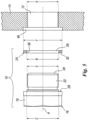
Figure 5 is a side view of the components of a preferred embodiment of the sealing device for bores of a heat exchanger according to the present invention; -
Figure 6 is a top view of the plug of the sealing device offigure 5 ; -
Figure 7 is an enlarged view of a portion of the plug of the sealing device offigure 5 ; and -
Figure 8 is an even more enlarged cross-sectional view of the plug portion offigure 7 , wherein the gasket too is shown. - With reference to the figures, a preferred embodiment of a sealing device for bores of a heat exchanger according to the present invention is shown. The sealing device is indicated as a whole with
reference numeral 10. The sealingdevice 10 is designed to seal a corresponding bore, in particular a bore obtained on the header of a heat exchanger. More specifically but not exclusively, the sealingdevice 10 is designed to seal acorresponding bore 12 obtained on aheader portion 14 of an air cooler heat exchanger, as shown infigure 5 . It should be noted that, in order to properly receive thesealing device 10, thebore 12 should be specifically machined, as will be better explained hereinafter with reference to the assembly method of said sealingdevice 10. - As shown in particular in
figures 5 to 8 , the sealingdevice 10 comprises at least one bolt-type plug 16, which is conventionally provided with ahead 18 and with a substantiallycylindrical shank 20. Theshank 20 has a threadedcylindrical surface 22 which is substantially parallel to a central rotation axis A of theplug 16. Theplug 16 is thus designed to be inserted into acorresponding bore 12 in a threaded coupling. - The sealing
device 10 also comprises at least oneannular gasket 24, which is provided with a central throughhole 26 having a predefined internal diameter B. Thegasket 24 is thus designed to be axially inserted around theshank 20 of theplug 16 to make seal between thehead 18 of theplug 16 and thebore 12 once the sealingdevice 10 has been properly inserted into saidbore 12. Thegasket 24 is preferably made of a metallic material. All metals can be adopted. Usually adopted metallic materials are carbon steel, stainless steel, nickel alloys and titanium. It should be noted that harder the gasket material, greater the need to have a perfect mating between thegasket 24 and its seats. - The
plug 16 is provided with at least oneannular seat 28 for accommodating thegasket 24. Thisannular seat 28 is arranged at a root connection between thehead 18 of theplug 16 and theshank 20 of theplug 16. More specifically, thisannular seat 28 comprises a radialannular contact surface 30, which is substantially flat in the radial direction and which is obtained on a lower portion of thehead 18 of theplug 16, that is, the portion of thehead 18 facing theshank 20. The radialannular contact surface 30 of theannular seat 28 is substantially perpendicular to the central rotation axis A of theplug 16. The radialannular contact surface 30 of theannular seat 28 is thus designed to be in contact with a radially orientedannular contact portion 32 of thegasket 24, that is, the portion of thegasket 24 which must guarantee the seal properties. - The
annular seat 28 also comprises an axialannular contact surface 34 which is substantially flat in the axial direction and which is obtained on a root portion of theshank 20 at the radialannular contact surface 30 of theannular seat 28. The axialannular contact surface 34 of theannular seat 28 is substantially parallel to the central rotation axis A of theplug 16. In other words, the radialannular contact surface 30 and the axialannular contact surface 34 of theannular seat 28 are perpendicular to each other. The axialannular contact surface 34 of theannular seat 28 has an internal diameter C which is substantially equal to the internal diameter B of the central throughhole 26 of the gasket. Therefore, the axialannular contact surface 34 of theannular seat 28 is designed to form an axial centering shoulder for thegasket 24, preferably through a direct contact between the innerannular surface 36 of thehole 26 and said axialannular contact surface 34 of theannular seat 28. - It should be pointed out that, in the present description and in the following claims, the term "axial" identifies any item which is parallel to the central rotation axis A of the
plug 16. Similarly, the term "radial" identifies any item which is perpendicular to the central rotation axis A of theplug 16. - According to the invention, as shown in
figure 7 and in more detail infigure 8 , the axialannular contact surface 34 of theannular seat 28 is provided with at least onecircumferential groove 38 having an internal diameter D which is smaller than the internal diameter C of said axialannular contact surface 34. With "internal diameter" D of thecircumferential groove 38 the diameter of the deepest portion of saidcircumferential groove 38 dug in the axialannular contact surface 34 is intended, as shown for example infigure 8 . This configuration of theannular seat 28 is an improvement of the prior art configuration shown infigure 4 . The purpose of this configuration is to allow the seating of thegasket 24 avoiding the problem of contact surface reduction. - Preferably, the
circumferential groove 38 is obtained on the axialannular contact surface 34 of theannular seat 28 at a joiningportion 40 between the radialannular contact surface 30 and said axialannular contact surface 34. In other words, this joiningportion 40 substantially coincides with the portion of the configuration shown infigure 3 wherein there is the root transition radius between axial and radial annular contact surfaces. Therefore, the fact that thecircumferential groove 38 is obtained at this joiningportion 40 allows complete seating of thegasket 24 in theannular seat 28, without any reduction in gasket contact width, for fa perfect gasket sealing. - Preferably, as shown for example in
figure 8 , thecircumferential groove 38 has a curve-shaped concave cross-section profile. More preferably, for ease of machining, thecircumferential groove 38 has a semicircular concave cross-section profile which causes saidcircumferential groove 38 to be tangential to the radialannular contact surface 30. In other words, as shown infigure 8 , there is preferably a continuity between the radialannular contact surface 30, which is flat, and thecircumferential groove 38 which, starting from saidflat surface 30, is dug in the axialannular contact surface 34. - To ensure a full contact between the
gasket 24 and the radialannular contact surface 30 of theannular seat 28, the radial width F of said radialannular contact surface 30 is preferably equal or greater than the radial width G of the radially orientedannular contact portion 32 of thegasket 24, that is, the sealing portion of saidgasket 24. For a similar sealing purpose, the axial thickness H of the innerannular surface 36 of thegasket hole 26, that is, the overall thickness of thegasket 24 measured along the central rotation axis A, is advantageously greater than the axial length K of thecircumferential groove 38. - Preferably, the threaded
cylindrical surface 22 of the substantiallycylindrical shank 20 has an overall diameter E which is smaller than the internal diameter C of the axialannular contact surface 34 of theannular seat 28. This feature has the purpose of allowing an easy axial movement of thegasket 24 around theshank 20 for the insertion of saidgasket 24 into itsannular seat 28 at the root of saidshank 20. Also preferably, a narrowedshank portion 42 is interposed between the threadedcylindrical surface 22 of theshank 20 and the axialannular contact surface 34 of theannular seat 28. For the same purpose as above, a frustoconical shankfitting portion 44 can be interposed between the narrowedshank portion 42 and the axialannular contact surface 34 of theannular seat 28. More specifically, the frustoconical shankfitting portion 44 has a smaller base which connects to said narrowedshank portion 42 and which has a smaller base diameter which is substantially equal to the overall diameter E of the threadedcylindrical surface 22, whereas the greater base of said frustoconical shankfitting portion 44 connects to the axialannular contact surface 34 of theannular seat 28 and has a greater base diameter which is substantially equal to the internal diameter C of said axialannular contact surface 34. - With specific reference to
figure 5 , the method for assembling the sealingdevice 10 described so far inside abore 12 obtained on aheader portion 14 of a heat exchanger is as follows. This assembling method initially requires a specific step of providing a through hole in saidheader portion 14, in order to obtain abore 12 having a diameter X which is substantially equal to the overall diameter E of the threadedcylindrical surface 22 of theshank 20. An internal thread in thebore 12 is to be provided. Preferably, to improve the sealing capability of thegasket 24 in the assembled configuration of the sealingdevice 10, the entrance of thebore 12 can be enlarged, in order to obtain anenlarged bore portion 46 having a flat peripheral annular surface which is perpendicular to the bore axis and having a diameter Y which is substantially equal to, or slightly greater than, the overall diameter of thegasket 24. - Once the
bore 12 and possibly the respectiveenlarged bore portion 46 have been completed, theshank 20 of theplug 16 is inserted into the central throughhole 26 of thegasket 24, in such a way that the radially orientedannular contact portion 32 of thegasket 24 comes into contact with the radialannular contact surface 30 of theannular seat 28 and the innerannular surface 36 of thegasket hole 26 comes into contact with the axialannular contact surface 34 of saidannular seat 28, except for a minimum gap to permit assembly. Actually, the manufacturing tolerances between the innerannular surface 36 of thegasket hole 26 and the axialannular contact surface 34 of theannular seat 28 have to be very narrow, to maintain as small as possible the gap between said two surfaces. - The
plug 16, with the properly centeredgasket 24, is then inserted into thebore 12 by screwing theshank 20 into the internal thread of said bore 12, in such a way that thegasket 24 comes into contact with theheader portion 14 and is fitted into its correspondingenlarged bore portion 46 if saidenlarged bore portion 46 is available. A tightening torque is finally applied to theplug head 18, in such a way that the radially orientedannular contact portion 32 of thegasket 24 is pushed in full and sealing contact with the radialannular contact surface 30 of theannular seat 28. - It is thus seen that the sealing device for bores of a heat exchanger according to the present invention achieve the previously outlined objects.
- The sealing device for bores of a heat exchanger of the present invention thus conceived is susceptible in any case of numerous modifications and variants, all falling within the same inventive concept; in addition, all the details can be substituted by technically equivalent elements. In practice, the materials used, as well as the shapes and size, can be of any type according to the technical requirements.
- The scope of protection of the invention is therefore defined by the enclosed claims.
-
- 10: sealing device;
- 12: bore;
- 14: heat exchanger header;
- 16: bolt-type plug;
- 18: plug head;
- 20: plug shank;
- 22: shank threaded cylindrical surface;
- 24: annular gasket;
- 26: gasket central through hole;
- 28: plug annular seat;
- 30: seat radial annular contact surface;
- 32: gasket radially oriented annular contact portion;
- 34: seat axial annular contact surface;
- 36: hole inner annular surface;
- 38: circumferential groove;
- 40: radial annular contact surface and axial annular contact surface joining portion;
- 42: narrowed skank portion;
- 44: frustoconical shank fitting portion;
- 46: enlarged bore portion;
- A: plug central rotation axis;
- B: hole internal diameter;
- C: axial annular contact surface internal diameter;
- D: circumferential groove internal diameter;
- E: threaded cylindrical surface overall diameter;
- F: radial annular contact surface width;
- G: radially oriented annular contact portion width;
- H: gasket axial thickness;
- K: groove axial length;
- X: bore diameter;
- Y: enlarged bore portion and gasket diameter.
Claims (12)
- A sealing device (10) for bores, in particular bores (12) obtained on a header portion (14) of a heat exchanger, the sealing device (10) comprising:- at least one bolt-type plug (16), which is provided with a head (18) and with a substantially cylindrical shank (20), wherein said shank (20) has a threaded cylindrical surface (22) which is substantially parallel to a central rotation axis (A) of said plug (16) and wherein said plug (16) is designed to be inserted into a corresponding bore (12) in a threaded coupling; and- at least one annular gasket (24), which is provided with a central through hole (26) having a predefined internal diameter (B), wherein said gasket (24) is designed to be axially inserted around said shank (20) to make seal between said head (18) and said bore (12),wherein said plug (16) is provided with at least one annular seat (28) for accommodating said gasket (24), wherein said seat (28) is arranged at a root connection between said head (18) and said shank (20), and wherein said seat (28) comprises:- a radial annular contact surface (30) which is substantially flat in the radial direction, which is obtained on a portion of said head (18) facing said shank (20) and which is substantially perpendicular to said central rotation axis (A), wherein said radial annular contact surface (30) is designed to be in contact with a radially oriented annular contact portion (32) of said gasket (24); and- an axial annular contact surface (34) which is substantially flat in the axial direction, which is obtained on a root portion of said shank (20) at said radial annular contact surface (30) and which is substantially parallel to said central rotation axis (A), wherein said axial annular contact surface (34) has an internal diameter (C) which is substantially equal to the internal diameter (B) of said central through hole (26), and wherein said axial annular contact surface (34) is designed to form an axial centering shoulder for said gasket (24),wherein said axial annular contact surface (34) is provided with at least one circumferential groove (38) having an internal diameter (D) which is smaller than the internal diameter (C) of said axial annular contact surface (34),the sealing device (10) being characterized in that said circumferential groove (38) is obtained on said axial annular contact surface (34) at a joining portion (40) between said radial annular contact surface (30) and said axial annular contact surface (34).
- The sealing device (10) according to claim 1, characterized in that said circumferential groove (38) has a curve-shaped concave cross-section profile.
- The sealing device (10) according to claim 2, characterized in that said circumferential groove (38) has a semicircular concave cross-section profile.
- The sealing device (10) according to anyone of claims 1 to 3, characterized in that the radial width (F) of said radial annular contact surface (30) is equal or greater than the radial width (G) of the radially oriented annular contact portion (32) of said gasket (24).
- The sealing device (10) according to anyone of claims 1 to 4, characterized in that the axial thickness (H) of the inner annular surface (36) of said gasket hole (26) is greater than the axial length (K) of said circumferential groove (38).
- The sealing device (10) according to anyone of claims 1 to 5, characterized in that the threaded cylindrical surface (22) of said substantially cylindrical shank (20) has an overall diameter (E) which is smaller than the internal diameter (C) of said axial annular contact surface (34).
- The sealing device (10) according to claim 6, characterized in that a narrowed shank portion (42) is interposed between said threaded cylindrical surface (22) and said axial annular contact surface (34).
- The sealing device (10) according to claim 7, characterized in that a frustoconical shank fitting portion (44) is interposed between said narrowed shank portion (42) and said axial annular contact surface (34).
- The sealing device (10) according to claim 8, characterized in that said frustoconical shank fitting portion (44) has a smaller base which connects to said narrowed shank portion (42) and which has a smaller base diameter which is substantially equal to the overall diameter (E) of said threaded cylindrical surface (22), whereas the greater base of said frustoconical shank fitting portion (44) connects to said axial annular contact surface (34) and has a greater base diameter which is substantially equal to the internal diameter (C) of said axial annular contact surface (34).
- The sealing device (10) according to anyone of claims 1 to 9, characterized in that said gasket (24) is made of a metallic material.
- A method for assembling the sealing device (10) according to anyone of the preceding claims inside a bore (12) obtained on a header portion (14) of a heat exchanger, the method comprising the steps of:- providing a through hole in said header portion (14), in order to obtain a bore (12) having a diameter (X) which is substantially equal to the overall diameter (E) of the threaded cylindrical surface (22) of said shank (20);- providing an internal thread in said bore (12);- inserting said shank (20) into the central through hole (26) of said gasket (24), in such a way that the radially oriented annular contact portion (32) of said gasket (24) comes into contact with the radial annular contact surface (30) of said annular seat (28) and the inner annular surface (36) of said hole (26) comes into contact with the axial annular contact surface (34) of said annular seat (28);- inserting said plug (16) into said bore (12) by screwing said shank (20) into the internal thread of said bore (12), in such a way that said gasket (24) comes into contact with said header portion (14); and- applying a tightening torque to said plug head (18), in such a way that the radially oriented annular contact portion (32) of said gasket (24) is pushed in full and sealing contact with the radial annular contact surface (30) of said annular seat (28).
- The method according to claim 11, further comprising the step of enlarging the entrance of said bore (12), in order to obtain an enlarged bore portion (46) having a flat peripheral annular surface which is perpendicular to the bore axis and having a diameter (Y) which is substantially equal to, or slightly greater than, the overall diameter of said gasket (24), in such a way that said gasket (24) is fitted into said enlarged bore portion (46) when said shank (20) is screwed into the internal thread of said bore (12).
Priority Applications (4)
| Application Number | Priority Date | Filing Date | Title |
|---|---|---|---|
| FIEP21425013.6T FI4067718T3 (en) | 2021-03-29 | 2021-03-29 | Sealing device for bores of a heat exchanger |
| ES21425013T ES2989123T3 (en) | 2021-03-29 | 2021-03-29 | Sealing device for holes in a heat exchanger |
| EP21425013.6A EP4067718B1 (en) | 2021-03-29 | 2021-03-29 | Sealing device for bores of a heat exchanger |
| PCT/EP2022/056973 WO2022207337A1 (en) | 2021-03-29 | 2022-03-17 | Sealing device for bores of a heat exchanger |
Applications Claiming Priority (1)
| Application Number | Priority Date | Filing Date | Title |
|---|---|---|---|
| EP21425013.6A EP4067718B1 (en) | 2021-03-29 | 2021-03-29 | Sealing device for bores of a heat exchanger |
Publications (2)
| Publication Number | Publication Date |
|---|---|
| EP4067718A1 EP4067718A1 (en) | 2022-10-05 |
| EP4067718B1 true EP4067718B1 (en) | 2024-09-11 |
Family
ID=75825799
Family Applications (1)
| Application Number | Title | Priority Date | Filing Date |
|---|---|---|---|
| EP21425013.6A Active EP4067718B1 (en) | 2021-03-29 | 2021-03-29 | Sealing device for bores of a heat exchanger |
Country Status (4)
| Country | Link |
|---|---|
| EP (1) | EP4067718B1 (en) |
| ES (1) | ES2989123T3 (en) |
| FI (1) | FI4067718T3 (en) |
| WO (1) | WO2022207337A1 (en) |
Family Cites Families (5)
| Publication number | Priority date | Publication date | Assignee | Title |
|---|---|---|---|---|
| US2325024A (en) * | 1941-04-24 | 1943-07-27 | Bowes Seal Fast Corp | Spark plug cooling means |
| US3850456A (en) * | 1971-02-22 | 1974-11-26 | Mc Donnell Douglas Corp | Lip seal fittings |
| US4783100A (en) * | 1987-04-20 | 1988-11-08 | Philips Industries, Inc. | Swivel joint |
| JP2005098378A (en) * | 2003-09-24 | 2005-04-14 | Smc Corp | gasket |
| EP1760381A1 (en) * | 2005-09-06 | 2007-03-07 | Siemens Aktiengesellschaft | Threaded fitting connection as well as fitting and axial sealing for such a threaded fitting connection and use of a threaded fitting connection |
-
2021
- 2021-03-29 ES ES21425013T patent/ES2989123T3/en active Active
- 2021-03-29 FI FIEP21425013.6T patent/FI4067718T3/en active
- 2021-03-29 EP EP21425013.6A patent/EP4067718B1/en active Active
-
2022
- 2022-03-17 WO PCT/EP2022/056973 patent/WO2022207337A1/en not_active Ceased
Also Published As
| Publication number | Publication date |
|---|---|
| ES2989123T3 (en) | 2024-11-25 |
| FI4067718T3 (en) | 2024-12-04 |
| WO2022207337A1 (en) | 2022-10-06 |
| EP4067718A1 (en) | 2022-10-05 |
Similar Documents
| Publication | Publication Date | Title |
|---|---|---|
| TWI534381B (en) | Method and structure for preventing pull-off of a fluor-resin tube fitting | |
| US20150069753A1 (en) | Advancements in mechanical sealing apparatus | |
| US8118528B2 (en) | Field replaceable hammer union wing nut apparatus and method | |
| US4214763A (en) | Bore seal | |
| US8657547B2 (en) | Hammer union wing nut | |
| US9417011B2 (en) | Heat exchanger with self-aligning fittings | |
| CA2972101C (en) | Swage fitting | |
| WO2018024174A1 (en) | Multi-petaled oblique-plane hoop and pipe connector thereof | |
| US20150076817A1 (en) | Composite sliding gasket for high-pressure joints | |
| US20130056978A1 (en) | Fluid coupling | |
| JP7045684B2 (en) | Pipe fittings | |
| EP3032158A1 (en) | Seal ring structure for high-pressure pipe joint | |
| US12292138B2 (en) | High temperature remotely connected/disconnected pipe connector for molten salt reactors | |
| EP0440733B1 (en) | Flanged connection for valves | |
| EP4067718A1 (en) | Sealing device for bores of a heat exchanger | |
| JP2007147011A (en) | Joint structure | |
| EP2458251B1 (en) | A composite sliding gasket for high-pressure joints | |
| EP0183510B1 (en) | A fitting for clamping a pipe | |
| JP5722645B2 (en) | Joint structure | |
| CN113217723B (en) | Flange connection sealing structure | |
| JP7555097B2 (en) | Pipe Fittings | |
| US12158224B2 (en) | Housing type pipe joint | |
| EP4067719B1 (en) | Improved sealing device for bores of a heat exchanger | |
| KR102918614B1 (en) | A rotor assembly of a gas turbine engine | |
| CN214618297U (en) | Pipe connector and aeroengine |
Legal Events
| Date | Code | Title | Description |
|---|---|---|---|
| PUAI | Public reference made under article 153(3) epc to a published international application that has entered the european phase |
Free format text: ORIGINAL CODE: 0009012 |
|
| STAA | Information on the status of an ep patent application or granted ep patent |
Free format text: STATUS: THE APPLICATION HAS BEEN PUBLISHED |
|
| AK | Designated contracting states |
Kind code of ref document: A1 Designated state(s): AL AT BE BG CH CY CZ DE DK EE ES FI FR GB GR HR HU IE IS IT LI LT LU LV MC MK MT NL NO PL PT RO RS SE SI SK SM TR |
|
| STAA | Information on the status of an ep patent application or granted ep patent |
Free format text: STATUS: REQUEST FOR EXAMINATION WAS MADE |
|
| 17P | Request for examination filed |
Effective date: 20230323 |
|
| RBV | Designated contracting states (corrected) |
Designated state(s): AL AT BE BG CH CY CZ DE DK EE ES FI FR GB GR HR HU IE IS IT LI LT LU LV MC MK MT NL NO PL PT RO RS SE SI SK SM TR |
|
| REG | Reference to a national code |
Ipc: F28F0011020000 Ref country code: DE Ref legal event code: R079 Ref document number: 602021018623 Country of ref document: DE Free format text: PREVIOUS MAIN CLASS: F16L0015040000 |
|
| GRAP | Despatch of communication of intention to grant a patent |
Free format text: ORIGINAL CODE: EPIDOSNIGR1 |
|
| STAA | Information on the status of an ep patent application or granted ep patent |
Free format text: STATUS: GRANT OF PATENT IS INTENDED |
|
| RIC1 | Information provided on ipc code assigned before grant |
Ipc: F16L 55/11 20060101ALI20240320BHEP Ipc: F16L 19/00 20060101ALI20240320BHEP Ipc: F16B 43/00 20060101ALI20240320BHEP Ipc: F16L 15/00 20060101ALI20240320BHEP Ipc: F16L 15/04 20060101ALI20240320BHEP Ipc: F28F 9/02 20060101ALI20240320BHEP Ipc: F28F 11/02 20060101AFI20240320BHEP |
|
| INTG | Intention to grant announced |
Effective date: 20240408 |
|
| GRAS | Grant fee paid |
Free format text: ORIGINAL CODE: EPIDOSNIGR3 |
|
| GRAA | (expected) grant |
Free format text: ORIGINAL CODE: 0009210 |
|
| STAA | Information on the status of an ep patent application or granted ep patent |
Free format text: STATUS: THE PATENT HAS BEEN GRANTED |
|
| P01 | Opt-out of the competence of the unified patent court (upc) registered |
Free format text: CASE NUMBER: APP_41122/2024 Effective date: 20240711 |
|
| AK | Designated contracting states |
Kind code of ref document: B1 Designated state(s): AL AT BE BG CH CY CZ DE DK EE ES FI FR GB GR HR HU IE IS IT LI LT LU LV MC MK MT NL NO PL PT RO RS SE SI SK SM TR |
|
| REG | Reference to a national code |
Ref country code: GB Ref legal event code: FG4D |
|
| REG | Reference to a national code |
Ref country code: CH Ref legal event code: EP |
|
| REG | Reference to a national code |
Ref country code: DE Ref legal event code: R096 Ref document number: 602021018623 Country of ref document: DE |
|
| REG | Reference to a national code |
Ref country code: IE Ref legal event code: FG4D |
|
| REG | Reference to a national code |
Ref country code: SE Ref legal event code: TRGR |
|
| REG | Reference to a national code |
Ref country code: NL Ref legal event code: FP |
|
| REG | Reference to a national code |
Ref country code: ES Ref legal event code: FG2A Ref document number: 2989123 Country of ref document: ES Kind code of ref document: T3 Effective date: 20241125 |
|
| REG | Reference to a national code |
Ref country code: FI Ref legal event code: FGE |
|
| REG | Reference to a national code |
Ref country code: LT Ref legal event code: MG9D |
|
| PG25 | Lapsed in a contracting state [announced via postgrant information from national office to epo] |
Ref country code: NO Free format text: LAPSE BECAUSE OF FAILURE TO SUBMIT A TRANSLATION OF THE DESCRIPTION OR TO PAY THE FEE WITHIN THE PRESCRIBED TIME-LIMIT Effective date: 20241211 |
|
| PG25 | Lapsed in a contracting state [announced via postgrant information from national office to epo] |
Ref country code: GR Free format text: LAPSE BECAUSE OF FAILURE TO SUBMIT A TRANSLATION OF THE DESCRIPTION OR TO PAY THE FEE WITHIN THE PRESCRIBED TIME-LIMIT Effective date: 20241212 |
|
| PG25 | Lapsed in a contracting state [announced via postgrant information from national office to epo] |
Ref country code: BG Free format text: LAPSE BECAUSE OF FAILURE TO SUBMIT A TRANSLATION OF THE DESCRIPTION OR TO PAY THE FEE WITHIN THE PRESCRIBED TIME-LIMIT Effective date: 20240911 |
|
| PG25 | Lapsed in a contracting state [announced via postgrant information from national office to epo] |
Ref country code: LV Free format text: LAPSE BECAUSE OF FAILURE TO SUBMIT A TRANSLATION OF THE DESCRIPTION OR TO PAY THE FEE WITHIN THE PRESCRIBED TIME-LIMIT Effective date: 20240911 |
|
| PG25 | Lapsed in a contracting state [announced via postgrant information from national office to epo] |
Ref country code: HR Free format text: LAPSE BECAUSE OF FAILURE TO SUBMIT A TRANSLATION OF THE DESCRIPTION OR TO PAY THE FEE WITHIN THE PRESCRIBED TIME-LIMIT Effective date: 20240911 |
|
| PG25 | Lapsed in a contracting state [announced via postgrant information from national office to epo] |
Ref country code: RS Free format text: LAPSE BECAUSE OF FAILURE TO SUBMIT A TRANSLATION OF THE DESCRIPTION OR TO PAY THE FEE WITHIN THE PRESCRIBED TIME-LIMIT Effective date: 20241211 |
|
| PG25 | Lapsed in a contracting state [announced via postgrant information from national office to epo] |
Ref country code: RS Free format text: LAPSE BECAUSE OF FAILURE TO SUBMIT A TRANSLATION OF THE DESCRIPTION OR TO PAY THE FEE WITHIN THE PRESCRIBED TIME-LIMIT Effective date: 20241211 Ref country code: NO Free format text: LAPSE BECAUSE OF FAILURE TO SUBMIT A TRANSLATION OF THE DESCRIPTION OR TO PAY THE FEE WITHIN THE PRESCRIBED TIME-LIMIT Effective date: 20241211 Ref country code: LV Free format text: LAPSE BECAUSE OF FAILURE TO SUBMIT A TRANSLATION OF THE DESCRIPTION OR TO PAY THE FEE WITHIN THE PRESCRIBED TIME-LIMIT Effective date: 20240911 Ref country code: HR Free format text: LAPSE BECAUSE OF FAILURE TO SUBMIT A TRANSLATION OF THE DESCRIPTION OR TO PAY THE FEE WITHIN THE PRESCRIBED TIME-LIMIT Effective date: 20240911 Ref country code: GR Free format text: LAPSE BECAUSE OF FAILURE TO SUBMIT A TRANSLATION OF THE DESCRIPTION OR TO PAY THE FEE WITHIN THE PRESCRIBED TIME-LIMIT Effective date: 20241212 Ref country code: BG Free format text: LAPSE BECAUSE OF FAILURE TO SUBMIT A TRANSLATION OF THE DESCRIPTION OR TO PAY THE FEE WITHIN THE PRESCRIBED TIME-LIMIT Effective date: 20240911 |
|
| REG | Reference to a national code |
Ref country code: AT Ref legal event code: MK05 Ref document number: 1723048 Country of ref document: AT Kind code of ref document: T Effective date: 20240911 |
|
| PG25 | Lapsed in a contracting state [announced via postgrant information from national office to epo] |
Ref country code: PT Free format text: LAPSE BECAUSE OF FAILURE TO SUBMIT A TRANSLATION OF THE DESCRIPTION OR TO PAY THE FEE WITHIN THE PRESCRIBED TIME-LIMIT Effective date: 20250113 Ref country code: IS Free format text: LAPSE BECAUSE OF FAILURE TO SUBMIT A TRANSLATION OF THE DESCRIPTION OR TO PAY THE FEE WITHIN THE PRESCRIBED TIME-LIMIT Effective date: 20250111 |
|
| PG25 | Lapsed in a contracting state [announced via postgrant information from national office to epo] |
Ref country code: RO Free format text: LAPSE BECAUSE OF FAILURE TO SUBMIT A TRANSLATION OF THE DESCRIPTION OR TO PAY THE FEE WITHIN THE PRESCRIBED TIME-LIMIT Effective date: 20240911 Ref country code: SM Free format text: LAPSE BECAUSE OF FAILURE TO SUBMIT A TRANSLATION OF THE DESCRIPTION OR TO PAY THE FEE WITHIN THE PRESCRIBED TIME-LIMIT Effective date: 20240911 |
|
| PG25 | Lapsed in a contracting state [announced via postgrant information from national office to epo] |
Ref country code: EE Free format text: LAPSE BECAUSE OF FAILURE TO SUBMIT A TRANSLATION OF THE DESCRIPTION OR TO PAY THE FEE WITHIN THE PRESCRIBED TIME-LIMIT Effective date: 20240911 Ref country code: AT Free format text: LAPSE BECAUSE OF FAILURE TO SUBMIT A TRANSLATION OF THE DESCRIPTION OR TO PAY THE FEE WITHIN THE PRESCRIBED TIME-LIMIT Effective date: 20240911 |
|
| PG25 | Lapsed in a contracting state [announced via postgrant information from national office to epo] |
Ref country code: PL Free format text: LAPSE BECAUSE OF FAILURE TO SUBMIT A TRANSLATION OF THE DESCRIPTION OR TO PAY THE FEE WITHIN THE PRESCRIBED TIME-LIMIT Effective date: 20240911 Ref country code: CZ Free format text: LAPSE BECAUSE OF FAILURE TO SUBMIT A TRANSLATION OF THE DESCRIPTION OR TO PAY THE FEE WITHIN THE PRESCRIBED TIME-LIMIT Effective date: 20240911 |
|
| PG25 | Lapsed in a contracting state [announced via postgrant information from national office to epo] |
Ref country code: SK Free format text: LAPSE BECAUSE OF FAILURE TO SUBMIT A TRANSLATION OF THE DESCRIPTION OR TO PAY THE FEE WITHIN THE PRESCRIBED TIME-LIMIT Effective date: 20240911 |
|
| REG | Reference to a national code |
Ref country code: DE Ref legal event code: R097 Ref document number: 602021018623 Country of ref document: DE |
|
| PG25 | Lapsed in a contracting state [announced via postgrant information from national office to epo] |
Ref country code: DK Free format text: LAPSE BECAUSE OF FAILURE TO SUBMIT A TRANSLATION OF THE DESCRIPTION OR TO PAY THE FEE WITHIN THE PRESCRIBED TIME-LIMIT Effective date: 20240911 |
|
| PGFP | Annual fee paid to national office [announced via postgrant information from national office to epo] |
Ref country code: ES Payment date: 20250411 Year of fee payment: 5 |
|
| PLBE | No opposition filed within time limit |
Free format text: ORIGINAL CODE: 0009261 |
|
| STAA | Information on the status of an ep patent application or granted ep patent |
Free format text: STATUS: NO OPPOSITION FILED WITHIN TIME LIMIT |
|
| 26N | No opposition filed |
Effective date: 20250612 |
|
| PG25 | Lapsed in a contracting state [announced via postgrant information from national office to epo] |
Ref country code: MC Free format text: LAPSE BECAUSE OF FAILURE TO SUBMIT A TRANSLATION OF THE DESCRIPTION OR TO PAY THE FEE WITHIN THE PRESCRIBED TIME-LIMIT Effective date: 20240911 |
|
| REG | Reference to a national code |
Ref country code: CH Ref legal event code: H13 Free format text: ST27 STATUS EVENT CODE: U-0-0-H10-H13 (AS PROVIDED BY THE NATIONAL OFFICE) Effective date: 20251024 |
|
| PG25 | Lapsed in a contracting state [announced via postgrant information from national office to epo] |
Ref country code: LU Free format text: LAPSE BECAUSE OF NON-PAYMENT OF DUE FEES Effective date: 20250329 |
|
| GBPC | Gb: european patent ceased through non-payment of renewal fee |
Effective date: 20250329 |
|
| PG25 | Lapsed in a contracting state [announced via postgrant information from national office to epo] |
Ref country code: GB Free format text: LAPSE BECAUSE OF NON-PAYMENT OF DUE FEES Effective date: 20250329 |
|
| PGFP | Annual fee paid to national office [announced via postgrant information from national office to epo] |
Ref country code: FI Payment date: 20251230 Year of fee payment: 6 |
|
| PGFP | Annual fee paid to national office [announced via postgrant information from national office to epo] |
Ref country code: FR Payment date: 20251231 Year of fee payment: 6 |
|
| PG25 | Lapsed in a contracting state [announced via postgrant information from national office to epo] |
Ref country code: CH Free format text: LAPSE BECAUSE OF NON-PAYMENT OF DUE FEES Effective date: 20250331 |
|
| PG25 | Lapsed in a contracting state [announced via postgrant information from national office to epo] |
Ref country code: IE Free format text: LAPSE BECAUSE OF NON-PAYMENT OF DUE FEES Effective date: 20250329 |
|
| PGFP | Annual fee paid to national office [announced via postgrant information from national office to epo] |
Ref country code: NL Payment date: 20260106 Year of fee payment: 6 |
|
| PGFP | Annual fee paid to national office [announced via postgrant information from national office to epo] |
Ref country code: SE Payment date: 20260105 Year of fee payment: 6 |
|
| PGFP | Annual fee paid to national office [announced via postgrant information from national office to epo] |
Ref country code: DE Payment date: 20260102 Year of fee payment: 6 |
|
| PGFP | Annual fee paid to national office [announced via postgrant information from national office to epo] |
Ref country code: BE Payment date: 20260105 Year of fee payment: 6 Ref country code: IT Payment date: 20260220 Year of fee payment: 6 |