EP4067661B1 - Oil tubing installation assembly and scroll compressor - Google Patents
Oil tubing installation assembly and scroll compressor Download PDFInfo
- Publication number
- EP4067661B1 EP4067661B1 EP22160597.5A EP22160597A EP4067661B1 EP 4067661 B1 EP4067661 B1 EP 4067661B1 EP 22160597 A EP22160597 A EP 22160597A EP 4067661 B1 EP4067661 B1 EP 4067661B1
- Authority
- EP
- European Patent Office
- Prior art keywords
- oil
- clip
- installation
- oil tubing
- installation block
- Prior art date
- Legal status (The legal status is an assumption and is not a legal conclusion. Google has not performed a legal analysis and makes no representation as to the accuracy of the status listed.)
- Active
Links
Images






Classifications
-
- F—MECHANICAL ENGINEERING; LIGHTING; HEATING; WEAPONS; BLASTING
- F04—POSITIVE - DISPLACEMENT MACHINES FOR LIQUIDS; PUMPS FOR LIQUIDS OR ELASTIC FLUIDS
- F04C—ROTARY-PISTON, OR OSCILLATING-PISTON, POSITIVE-DISPLACEMENT MACHINES FOR LIQUIDS; ROTARY-PISTON, OR OSCILLATING-PISTON, POSITIVE-DISPLACEMENT PUMPS
- F04C29/00—Component parts, details or accessories of pumps or pumping installations, not provided for in groups F04C18/00 - F04C28/00
- F04C29/02—Lubrication; Lubricant separation
- F04C29/028—Means for improving or restricting lubricant flow
-
- F—MECHANICAL ENGINEERING; LIGHTING; HEATING; WEAPONS; BLASTING
- F04—POSITIVE - DISPLACEMENT MACHINES FOR LIQUIDS; PUMPS FOR LIQUIDS OR ELASTIC FLUIDS
- F04C—ROTARY-PISTON, OR OSCILLATING-PISTON, POSITIVE-DISPLACEMENT MACHINES FOR LIQUIDS; ROTARY-PISTON, OR OSCILLATING-PISTON, POSITIVE-DISPLACEMENT PUMPS
- F04C18/00—Rotary-piston pumps specially adapted for elastic fluids
- F04C18/02—Rotary-piston pumps specially adapted for elastic fluids of arcuate-engagement type, i.e. with circular translatory movement of co-operating members, each member having the same number of teeth or tooth-equivalents
- F04C18/0207—Rotary-piston pumps specially adapted for elastic fluids of arcuate-engagement type, i.e. with circular translatory movement of co-operating members, each member having the same number of teeth or tooth-equivalents both members having co-operating elements in spiral form
- F04C18/0215—Rotary-piston pumps specially adapted for elastic fluids of arcuate-engagement type, i.e. with circular translatory movement of co-operating members, each member having the same number of teeth or tooth-equivalents both members having co-operating elements in spiral form where only one member is moving
-
- F—MECHANICAL ENGINEERING; LIGHTING; HEATING; WEAPONS; BLASTING
- F04—POSITIVE - DISPLACEMENT MACHINES FOR LIQUIDS; PUMPS FOR LIQUIDS OR ELASTIC FLUIDS
- F04C—ROTARY-PISTON, OR OSCILLATING-PISTON, POSITIVE-DISPLACEMENT MACHINES FOR LIQUIDS; ROTARY-PISTON, OR OSCILLATING-PISTON, POSITIVE-DISPLACEMENT PUMPS
- F04C23/00—Combinations of two or more pumps, each being of rotary-piston or oscillating-piston type, specially adapted for elastic fluids; Pumping installations specially adapted for elastic fluids; Multi-stage pumps specially adapted for elastic fluids
- F04C23/008—Hermetic pumps
-
- F—MECHANICAL ENGINEERING; LIGHTING; HEATING; WEAPONS; BLASTING
- F16—ENGINEERING ELEMENTS AND UNITS; GENERAL MEASURES FOR PRODUCING AND MAINTAINING EFFECTIVE FUNCTIONING OF MACHINES OR INSTALLATIONS; THERMAL INSULATION IN GENERAL
- F16L—PIPES; JOINTS OR FITTINGS FOR PIPES; SUPPORTS FOR PIPES, CABLES OR PROTECTIVE TUBING; MEANS FOR THERMAL INSULATION IN GENERAL
- F16L7/00—Supporting pipes or cables inside other pipes or sleeves, e.g. for enabling pipes or cables to be inserted or withdrawn from under roads or railways without interruption of traffic
-
- F—MECHANICAL ENGINEERING; LIGHTING; HEATING; WEAPONS; BLASTING
- F04—POSITIVE - DISPLACEMENT MACHINES FOR LIQUIDS; PUMPS FOR LIQUIDS OR ELASTIC FLUIDS
- F04C—ROTARY-PISTON, OR OSCILLATING-PISTON, POSITIVE-DISPLACEMENT MACHINES FOR LIQUIDS; ROTARY-PISTON, OR OSCILLATING-PISTON, POSITIVE-DISPLACEMENT PUMPS
- F04C2240/00—Components
- F04C2240/30—Casings or housings
-
- F—MECHANICAL ENGINEERING; LIGHTING; HEATING; WEAPONS; BLASTING
- F04—POSITIVE - DISPLACEMENT MACHINES FOR LIQUIDS; PUMPS FOR LIQUIDS OR ELASTIC FLUIDS
- F04C—ROTARY-PISTON, OR OSCILLATING-PISTON, POSITIVE-DISPLACEMENT MACHINES FOR LIQUIDS; ROTARY-PISTON, OR OSCILLATING-PISTON, POSITIVE-DISPLACEMENT PUMPS
- F04C2240/00—Components
- F04C2240/80—Other components
- F04C2240/806—Pipes for fluids; Fittings therefor
Definitions
- Embodiments of the disclosure relate to an oil tubing installation assembly and a scroll compressor.
- the length of the oil tubing installed on the housing is short, or when the oil tubing is installed to the housing from the inside of the housing, the existing oil tubing with short length is difficult to meet the functional requirements of both maintaining a low oil circulation rate and drawing excess oil away from the housing. Therefore, it is desirable to use an oil tubing with longer length in the compressor. However, it is difficult for the existing assembling tools to meet the assembling requirements of the new type compressors with a longer oil tubing.
- WO 2017/106030A1 describes a scroll compressor that includes a housing and scroll compressor bodies disposed in the housing.
- An oil return tube delivers oil from an upper region of the housing to an oil sump in a lower region of the housing.
- EP 3 290 711 A1 describes a refrigerant compressor.
- EP 2 527 654 A1 describes a compressor that is equipped with a casing, a compression mechanism, a drive shaft, a main frame, a motor, a flow path forming member and temperature sensing member.
- threaded holes are provided on the oil tubing installation surface.
- the clip is configured to also have third tongues.
- Each of the third tongues respectively extends to the left and right sides from the vertical edge of the two vertical edges of the corresponding one of the second tongues which is closer to the oil tubing installation surface.
- Through holes are provided in the third tongues. The through holes in the third tongues are aligned with the threaded holes on the oil tubing installation surface after the clip is installed in place on the oil tubing installation surface so as to fasten the clip to the housing with screws going through the through holes in the third tongues and the threaded holes on the oil tubing installation surface.
- the housing is configured to have an outer peripheral surface
- the oil tubing installation surface is located on the outer peripheral surface and is radially inwardly offset relative to the outer peripheral surface, so as to form a first stepped surface at the junction of the outer peripheral surface and the oil tubing installation surface.
- a lower bottom surface is provided below the oil tubing installation surface.
- the lower bottom surface is adjacent to and perpendicular to the oil tubing installation surface.
- the rear surface of the installation block comprises an upper rear surface and a lower rear surface.
- the second orifice is located in the lower rear surface.
- a second stepped surface is formed at the junction of the upper rear surface and the lower rear surface.
- the installation block further comprises a bottom surface.
- the bottom plate of the clip is inserted under the lower bottom surface and abutted on the lower bottom surface and the bottom surface of the installation block abuts on the bottom plate of the clip after the clip is installed in place on the oil tubing installation surface and the installation block is installed in place in the clip.
- the distance from the center of the oil hole to the lower bottom surface is equal to the distance from the center of the second orifice to the bottom surface of the installation block, and the distance from the center of the oil hole to the first stepped surface is greater than or equal to the distance from the center of the second orifice to the second stepped surface.
- a flange is provided on the second orifice.
- the flange of the second orifice is embedded tightly into the oil hole when the second orifice is aligned with and fitted to the oil hole.
- the distance between the second tongue on the left side and the second tongue on the right side is equal to the dimension of the installation block in the left-right direction, and is smaller than or equal to the dimension of the first stepped surface in the left-right direction.
- a scroll compressor is provided.
- the scroll compressor comprises a shell and an oil tubing installation assembly according to the preceding aspects.
- the oil tubing installation assembly is adapted to be installed into the shell in a vertical direction.
- the long oil tubing can be more easily installed into a mid-shell of a compressor on a production line of the compressor and is not limited by the existing assembling tools by adopting the oil tubing installation assembly of the present disclosure. In this way, it is possible to efficiently manufacture a compressor, particularly a scroll compressor, which meets the functional requirements of maintaining a low oil circulation rate and drawing excess oil away from a housing.
- FIG. 3 is a perspective view of a housing according to an exemplary embodiment of the present disclosure.
- the housing 10 has an outer peripheral surface 101.
- the vertical oil tubing installation surface 102 is located on the outer peripheral surface 101 and is radially inwardly offset relative to the outer peripheral surface 101, so as to form a stepped surface 103 at the junction of the outer peripheral surface 101 and the oil tubing installation surface102.
- a lower bottom surface 104 is provided below the oil tubing installation surface 102.
- the lower bottom surface 104 is adjacent to and perpendicular to the oil tubing installation surface 102.
- An oil hole 105 and two threaded holes 106, 106' are opened in the oil tubing installation surface 102.
- the distance from the center of the oil hole 105 to the lower bottom surface 104 is h1, and the distance from the center of the oil hole to the stepped surface 103 is h2.
- the dimension of the stepped surface 103 in the left-right direction is L1.
- the upper end 4031 of the first elastic tongue 403 is bent to the outside and can abut against the inner wall of the mid-shell 20.
- the lower end 4032 of the first elastic tongue 403 is arc-shaped, so that the elasticity of the first elastic tongue 403 can be increased.
- the upper end 4031 of the first elastic tongue 403 and the lower end 4032 of the first elastic tongue 403 are connected by a straight middle section.
- a turning area s is formed at the junction of the upper end 4031 of the first elastic tongue 403 and the middle section.
- the through holes 4021, 4021' in the third tongues 402, 402' are aligned with the threaded holes 106, 106' on the oil tubing installation surface 102 after the clip 40 is installed in place on the oil tubing installation surface 102 so as to fasten the clip 40 to the housing 10 with screws going through the through holes 4021, 4021' in the third tongues 402, 402' and the threaded holes 106, 106' on the oil tubing installation surface 102.
- the bottom plate 401 of the clip 40 is inserted under the lower bottom surface 104 of the housing 10 and abutted on the lower bottom surface 104 after the clip 40 is installed in place on the oil tubing installation surface 102.
- grooves 5011, 5011' are provided on the front surface 501 of the installation block 50.
- the first elastic tongue 403 (especially the turning area s) can be embedded into the groove 5011
- the first elastic tongue 403' (especially the turning area s') can be embedded into the groove 5011'.
- the rear surface 503 of the installation block comprises an upper rear surface 5031 and a lower rear surface 5032.
- the second orifice is located in the lower rear surface 5032.
- a stepped surface 5033 is formed at the junction of the upper rear surface 5031 and the lower rear surface 5032.
- the dimension of the installation block in the left-right direction is L3.
- L3 L2 ⁇ L1.
- FIG. 6 is a schematic diagram of a state in the process of installing the oil tubing assembly shown in FIG. 5A to the clip shown in FIG. 4A .
- FIG. 7A is a perspective view of a state prior to assembling an oil tubing assembly into a mid-shell of a compressor according to an exemplary embodiment of the present disclosure.
- FIG. 7B is a partially cutaway side view of a state prior to assembling an oil tubing assembly into a mid-shell of a compressor according to an exemplary embodiment of the present disclosure.
- FIG. 8A is a perspective view of a state after assembling an oil tubing assembly into a mid-shell of the compressor according to an exemplary embodiment of the present disclosure.
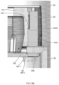
- FIG. 8B is a partially cutaway side view of the state shown in FIG. 8A .
- the installation block 50 When the installation block 50 is installed in place in the clip 40, the second orifice is aligned with the oil hole 105, the bottom surface 505 of the installation block 50 abuts on the bottom plate 401 of the clip 40, the stepped surface 5033 quickly passes the stepped surface 103, and the installation block 50 is quickly approached to the oil tubing installation surface 102 under the pushing force of the first elastic tongues 403 and 403', so that the flange 5071 of the second orifice is embedded in the oil hole 105. At this point, the oil tubing assembly will "click" and be audible to the operator. The operator can thus know that the oil tubing assembly is already in place.
Landscapes
- Engineering & Computer Science (AREA)
- General Engineering & Computer Science (AREA)
- Mechanical Engineering (AREA)
- Rotary Pumps (AREA)
- Supports For Pipes And Cables (AREA)
Description
- Embodiments of the disclosure relate to an oil tubing installation assembly and a scroll compressor.
- In most of the current compressors, the length of the oil tubing installed on the housing is short, or when the oil tubing is installed to the housing from the inside of the housing, the existing oil tubing with short length is difficult to meet the functional requirements of both maintaining a low oil circulation rate and drawing excess oil away from the housing. Therefore, it is desirable to use an oil tubing with longer length in the compressor. However, it is difficult for the existing assembling tools to meet the assembling requirements of the new type compressors with a longer oil tubing.
-
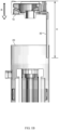
FIG. 1A is a perspective view of a state prior to assembling a housing with an oil tubing into a mid-shell of a compressor in the prior art,FIG. 1B is a partially cutaway side view of the state shown inFIG. 1A ,FIG. 2A is a perspective view of a state after assembling a housing with an oil tubing into a mid-shell of a compressor in the prior art, andFIG. 2B is a partially cutaway side view of the state shown inFIG. 2A . - Specifically, on one hand, as shown in
FIGS. 1A to 2B , in order to assemble thehousing 10 with theoil tubing 30 into themid-shell 20 of the compressor 1, it is necessary to use an assembling tool (not shown in the drawings) to raise thehousing 10 to a certain height (H) so that the lower end of theoil tubing 30 can be placed into themid-shell 20, and then thehousing 10 with theoil tubing 30 can be assembled into themid-shell 20 in the vertically downward direction R. In this case, in order to assemble thehousing 10 with a longer oil tubing into themid-shell 20, it is necessary to increase the stroke of the assembling tool to increase the height to which thehousing 10 is raised. However, in the prior art, due to the limitation of the structural size of the assembling tool itself, the height to which thehousing 10 is raised is limited. - On the other hand, if the
oil tubing 30 is assembled separately after thehousing 10 has been installed into the mid-shell 20, it is difficult to assemble theoil tubing 30 to thehousing 10 in themid-shell 20 since the residual space (D) between thehousing 10 and the mid-shell 20 is too small. -
WO 2017/106030A1 describes a scroll compressor that includes a housing and scroll compressor bodies disposed in the housing. An oil return tube delivers oil from an upper region of the housing to an oil sump in a lower region of the housing. -
EP 3 290 711 A1 describes a refrigerant compressor. -
EP 2 527 654 A1 describes a compressor that is equipped with a casing, a compression mechanism, a drive shaft, a main frame, a motor, a flow path forming member and temperature sensing member. - The disclosure is made in order to solve the problem that the oil tubing is difficult to be installed into the mid-shell of the compressor together with the housing due to its too long length, and other potential technical problems.
- According to the present invention, there is provided a scroll compressor according to the subject-matter of claim 1.
- Specifically, the clip is configured to have a horizontal bottom plate and first elastic tongues extending upward from the front edge of the bottom plate. The first elastic tongues are configured to be in contact with the front surface of the installation block and apply pressure to the front surface of the installation block, so that the rear surface of the installation block is abutted on the oil tubing installation surface and the second orifice is tightly fitted to the oil hole after the installation block is installed in place in the clip.
- Preferably, the upper ends of the first elastic tongues are bent to the outside and able to abut against the inner wall of the shell.
- Preferably, grooves are provided on the front surface of the installation block. The first elastic tongues can be embedded into the corresponding grooves after the installation block is installed in place in the clip.
- Optionally, the clip is configured to have second tongues extending upward respectively from the left and right edges of the bottom plate. The second tongues are configured to be respectively in contact with and apply pressure to the left and right sides of the installation block to inhibit the movement of the installation block in the left-right direction.
- Preferably, the upper ends of the second tongues are bent to the outside.
- Specifically, threaded holes are provided on the oil tubing installation surface. The clip is configured to also have third tongues. Each of the third tongues respectively extends to the left and right sides from the vertical edge of the two vertical edges of the corresponding one of the second tongues which is closer to the oil tubing installation surface. Through holes are provided in the third tongues. The through holes in the third tongues are aligned with the threaded holes on the oil tubing installation surface after the clip is installed in place on the oil tubing installation surface so as to fasten the clip to the housing with screws going through the through holes in the third tongues and the threaded holes on the oil tubing installation surface.
- Specifically, the housing is configured to have an outer peripheral surface, the oil tubing installation surface is located on the outer peripheral surface and is radially inwardly offset relative to the outer peripheral surface, so as to form a first stepped surface at the junction of the outer peripheral surface and the oil tubing installation surface. A lower bottom surface is provided below the oil tubing installation surface. The lower bottom surface is adjacent to and perpendicular to the oil tubing installation surface. The rear surface of the installation block comprises an upper rear surface and a lower rear surface. The second orifice is located in the lower rear surface. A second stepped surface is formed at the junction of the upper rear surface and the lower rear surface. The installation block further comprises a bottom surface. The bottom plate of the clip is inserted under the lower bottom surface and abutted on the lower bottom surface and the bottom surface of the installation block abuts on the bottom plate of the clip after the clip is installed in place on the oil tubing installation surface and the installation block is installed in place in the clip. The distance from the center of the oil hole to the lower bottom surface is equal to the distance from the center of the second orifice to the bottom surface of the installation block, and the distance from the center of the oil hole to the first stepped surface is greater than or equal to the distance from the center of the second orifice to the second stepped surface.
- Optionally, a flange is provided on the second orifice. The flange of the second orifice is embedded tightly into the oil hole when the second orifice is aligned with and fitted to the oil hole. Specifically, the distance between the second tongue on the left side and the second tongue on the right side is equal to the dimension of the installation block in the left-right direction, and is smaller than or equal to the dimension of the first stepped surface in the left-right direction. According to another aspect of the present disclosure, a scroll compressor is provided. The scroll compressor comprises a shell and an oil tubing installation assembly according to the preceding aspects. The oil tubing installation assembly is adapted to be installed into the shell in a vertical direction.
- The long oil tubing can be more easily installed into a mid-shell of a compressor on a production line of the compressor and is not limited by the existing assembling tools by adopting the oil tubing installation assembly of the present disclosure. In this way, it is possible to efficiently manufacture a compressor, particularly a scroll compressor, which meets the functional requirements of maintaining a low oil circulation rate and drawing excess oil away from a housing.
- In order to facilitate understanding of the present disclosure, the present disclosure is hereinafter described in more detail based on exemplary embodiments and in conjunction with the accompanying drawings. The same or similar reference numbers are used in the accompanying drawings to refer to the same or similar components. It should be understood that the accompanying drawings are schematic only and that the dimensions and proportions of components in the accompanying drawings are not necessarily precise.
-
FIG. 1A is a perspective view of a state prior to assembling a housing with an oil tubing into a mid-shell of a compressor in the prior art; -
FIG. 1B is a partially cutaway side view of the state shown inFIG. 1A ; -
FIG. 2A is a perspective view of a state after a housing with an oil tubing is assembled into a mid-shell of a compressor in the prior art; -
FIG. 2B is a partially cutaway side view of the state shown inFIG. 2A ; -
FIG. 3 is a perspective view of a housing according to an exemplary embodiment of the present disclosure; -
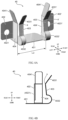
FIGS. 4A and 4B are respectively a perspective view and a side view of a clip according to an exemplary embodiment of the present disclosure; -
FIGS. 5A and 5B are perspective views of an oil tubing assembly according to an exemplary embodiment of the present disclosure; -
FIG. 6 is a schematic diagram of a state in the process of installing the oil tubing assembly shown inFIG. 5A to the clip shown inFIG. 4A ; -
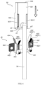
FIG. 7A is a perspective view of a state prior to assembling an oil tubing assembly into a mid-shell of a compressor according to an exemplary embodiment of the present disclosure; -
FIG. 7B is a partially cutaway side view of a state prior to assembling an oil tubing assembly into a mid-shell of a compressor according to an exemplary embodiment of the present disclosure; -
FIG. 8A is a perspective view of a state after assembling an oil tubing assembly into a mid-shell of the compressor according to an exemplary embodiment of the present disclosure; and -
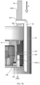
FIG. 8B is a partially cutaway side view of the state shown inFIG. 8A . - Hereinafter, the present disclosure is described in detail with reference to the accompanying drawings.
-
FIG. 3 is a perspective view of a housing according to an exemplary embodiment of the present disclosure. - As shown in
FIG. 3 , thehousing 10 has an outerperipheral surface 101. The vertical oiltubing installation surface 102 is located on the outerperipheral surface 101 and is radially inwardly offset relative to the outerperipheral surface 101, so as to form a steppedsurface 103 at the junction of the outerperipheral surface 101 and the oil tubing installation surface102. Alower bottom surface 104 is provided below the oiltubing installation surface 102. Thelower bottom surface 104 is adjacent to and perpendicular to the oiltubing installation surface 102. Anoil hole 105 and two threadedholes 106, 106' are opened in the oiltubing installation surface 102. The distance from the center of theoil hole 105 to thelower bottom surface 104 is h1, and the distance from the center of the oil hole to the steppedsurface 103 is h2. The dimension of the steppedsurface 103 in the left-right direction is L1. -
FIGS. 4A and 4B are respectively a perspective view and a side view of a clip according to an exemplary embodiment of the present disclosure. Theclip 40 is adapted to be installed on the oiltubing installation surface 102 and into the mid-shell 20 along with thehousing 10. As shown inFIGS. 4A and 4B , theclip 40 is configured to have ahorizontal bottom plate 401 and firstelastic tongues bottom plate 401. As will be described later, the firstelastic tongues front surface 501 of theinstallation block 50 and apply pressure to thefront surface 501 of theinstallation block 50, so that therear surface 503 of theinstallation block 50 is abutted on the oiltubing installation surface 102 and thesecond orifice 507 is tightly fitted to theoil hole 105 after theinstallation block 50 is installed in place in theclip 40. It should be understood that, although the number of the first elastic tongues shown inFIGS. 4A and 4B is two, in practice the number of the first elastic tongues may be less or more than two. - Taking the first
elastic tongue 403 as an example, theupper end 4031 of the firstelastic tongue 403 is bent to the outside and can abut against the inner wall of the mid-shell 20. Thelower end 4032 of the firstelastic tongue 403 is arc-shaped, so that the elasticity of the firstelastic tongue 403 can be increased. Theupper end 4031 of the firstelastic tongue 403 and thelower end 4032 of the firstelastic tongue 403 are connected by a straight middle section. A turning area s is formed at the junction of theupper end 4031 of the firstelastic tongue 403 and the middle section. As will be described later, the first elastic tongue 403 (specifically, the turning area s) can be embedded in thecorresponding groove 5011 of theinstallation block 50 after theinstallation block 50 is installed in place in theclip 40, so as to exert pressure to thefront surface 501 of theinstallation block 50 and have a certain limiting effect on theinstallation block 50. The structure of the first elastic tongue is described above by taking the firstelastic tongue 403 as an example. The structure of the other firstelastic tongue 403' is the same with that of the firstelastic tongue 403, so its structure is not repeated here, but only a corner mark' is added to the upper right corner of the corresponding reference number in the accompanying drawings to distinguish it from the corresponding structure of the firstelastic tongue piece 403. - The
clip 40 is configured to havesecond tongues second tongues left side 502 and the right side 502' of theinstallation block 50 to inhibit the movement of theinstallation block 50 in the left-right direction. The distance between thesecond tongues installation block 50. - The
clip 40 is configured to also have twothird tongues 402, 402'. Thethird tongue 402 extends to the left side from the vertical edge of the two vertical edges of thesecond tongue 404 that is closer to the oiltubing installation surface 102, and the third tongue 402' extends to the right side from the vertical edge of the two vertical edges of thesecond tongue 404' that is closer to the oiltubing installation surface 102. Throughholes 4021, 4021' are opened in thethird tongues 402, 402'. It should be understood that, although the number of the throughholes 4021, 4021' shown inFIGS. 4A and 4B is two, in practice the number of the through holes may be less or more than two. - The through
holes 4021, 4021' in thethird tongues 402, 402' are aligned with the threadedholes 106, 106' on the oiltubing installation surface 102 after theclip 40 is installed in place on the oiltubing installation surface 102 so as to fasten theclip 40 to thehousing 10 with screws going through the throughholes 4021, 4021' in thethird tongues 402, 402' and the threadedholes 106, 106' on the oiltubing installation surface 102. Thebottom plate 401 of theclip 40 is inserted under thelower bottom surface 104 of thehousing 10 and abutted on thelower bottom surface 104 after theclip 40 is installed in place on the oiltubing installation surface 102. -
FIGS. 5A and 5B are perspective views of an oil tubing assembly according to an exemplary embodiment of the present disclosure. The oil tubing assembly is adapted to be installed into theclip 40 in a vertically downward direction R after thehousing 10 and theclip 40 have been installed into the mid-shell 20. - As shown in
FIGS. 5A and 5B , the oil tubing assembly comprises anoil tubing body 30 and an overall cuboid-shapedinstallation block 50. A throughhole 507 is provided in theinstallation block 50. The throughhole 507 is configured to have a first orifice on thefront surface 501 of theinstallation block 50 and a second orifice on therear surface 503 of the installation block. The upper end of theoil tubing body 30 is connected to the first orifice. The second orifice is aligned with and fitted to the oil hole 405 after theinstallation block 50 is installed in place in theclip 40. Preferably, aflange 5071 is provided on the second orifice. In this way, theflange 5071 can be embedded tightly into theoil hole 105 when the second orifice is aligned with and fitted to theoil hole 105. - Specifically,
grooves front surface 501 of theinstallation block 50. After theinstallation block 50 is installed in place in theclip 40, the first elastic tongue 403 (especially the turning area s) can be embedded into thegroove 5011, and the firstelastic tongue 403' (especially the turning area s') can be embedded into thegroove 5011'. Therear surface 503 of the installation block comprises an upperrear surface 5031 and a lowerrear surface 5032. The second orifice is located in the lowerrear surface 5032. A steppedsurface 5033 is formed at the junction of the upperrear surface 5031 and the lowerrear surface 5032. -
Installation block 50 also comprises abottom surface 505 and atop surface 506. A chamfered face w1 is formed at the junction of thebottom surface 505 and thefront surface 501. Chamfered faces w2 and w2' are formed respectively at the junctions of thebottom surface 505 and theleft side surface 502 and the right side surface 502' of theinstallation block 50. In addition, the distance from the center of the second orifice to thebottom surface 505 is h3, and the distance from the center of the second orifice to the steppedsurface 5033 is h4. - The
bottom plate 401 of theclip 40 is abutted on thelower bottom surface 104 of thehousing 10 after theclip 40 is installed in place on the oiltubing installation surface 102 and theinstallation block 50 is installed in place in theclip 40. Preferably, h1=h3, and h2≥h4. - The dimension of the installation block in the left-right direction is L3. Preferably, L3=L2≤L1.
-
FIG. 6 is a schematic diagram of a state in the process of installing the oil tubing assembly shown inFIG. 5A to the clip shown inFIG. 4A .FIG. 7A is a perspective view of a state prior to assembling an oil tubing assembly into a mid-shell of a compressor according to an exemplary embodiment of the present disclosure.FIG. 7B is a partially cutaway side view of a state prior to assembling an oil tubing assembly into a mid-shell of a compressor according to an exemplary embodiment of the present disclosure.FIG. 8A is a perspective view of a state after assembling an oil tubing assembly into a mid-shell of the compressor according to an exemplary embodiment of the present disclosure.FIG. 8B is a partially cutaway side view of the state shown inFIG. 8A . - As shown in
FIGS. 6 to 8B , theclip 40 may be pre-fixed to thehousing 10 and then installed into the mid-shell 20 together with thehousing 10. Then, the oil tubing assembly (i.e., theinstallation block 50 with the oil tubing 30) is pressed into theclip 40 in the vertically downward direction R. Specifically, as the oil tubing assembly continues to move downward in the vertically downward direction R, the chamfered face w1 comes in contact with the upper ends 4031, 4031' of the firstelastic tongues second tongues elastic tongues corresponding grooves installation block 50, respectively. - When the
installation block 50 is installed in place in theclip 40, the second orifice is aligned with theoil hole 105, thebottom surface 505 of theinstallation block 50 abuts on thebottom plate 401 of theclip 40, the steppedsurface 5033 quickly passes the steppedsurface 103, and theinstallation block 50 is quickly approached to the oiltubing installation surface 102 under the pushing force of the firstelastic tongues flange 5071 of the second orifice is embedded in theoil hole 105. At this point, the oil tubing assembly will "click" and be audible to the operator. The operator can thus know that the oil tubing assembly is already in place.
Claims (10)
- A scroll compressor,
the scroll compressor comprising:a shell (20),a housing (10) andan oil tubing installation assembly installed into the shell (20) in a vertical direction, whereinthe oil tubing installation assembly comprising:a vertical oil tubing installation surface (102) and an oil hole (105) located in the oil tubing installation surface being provided on the housing (10);characterized by the oil tubing installation assembly comprising:a clip (40) adapted to be installed on the oil tubing installation surface and into the shell along with the housing; andan oil tubing assembly adapted to be installed into the clip in a vertical direction after the housing and the clip have been installed into the shell,wherein the oil tubing assembly comprises an oil tubing body (30) and an overall cuboid-shaped installation block (50) in which a through hole (507) is provided, the through hole is configured to have a first orifice on the front surface (501) of the installation block and a second orifice on the rear surface (503) of the installation block, and the upper end of the oil tubing body is connected to the first orifice, andwherein the second orifice is aligned with and fitted to the oil hole after the installation block is installed in place in the clip. - The scroll compressor according to claim 1, characterized in that the clip is configured to have a horizontal bottom plate (401) and first elastic tongues (403, 403') extending upward from the front edge of the bottom plate,
wherein, the first elastic tongues are configured to be in contact with the front surface of the installation block and apply pressure to the front surface of the installation block, so that the rear surface of the installation block is abutted on the oil tubing installation surface and the second orifice is tightly fitted to the oil hole after the installation block is installed in place in the clip. - The scroll compressor according to claim 2, characterized in that the upper ends of the first elastic tongues are bent to the outside and can be abutted against the inner wall of the shell
- The scroll compressor according to claim 3, characterized in that grooves (5011, 5011') are provided on the front surface of the installation block;
wherein the first elastic tongues are embeddable into the corresponding grooves after the installation block is installed in place in the clip - The scroll compressor according to any one of claims 2 to 4, characterized in that the clip is configured to have second tongues (404, 404') extending upward respectively from the left and right edges of the bottom plate, and the second tongues are configured to be respectively in contact with and apply pressure to the left and right sides of the installation block to inhibit the movement of the installation block in the left-right direction
- The oil scroll compressor assembly according to claim 5, characterized in that the upper ends of the second tongues are bent to the outside.
- The scroll compressor according to claim 6, characterized in that threaded holes (106, 106') are provided on the oil tubing installation surface,the clip is configured to also have third tongues (402, 402'), each of the third tongues respectively extending to the left and right sides from the vertical edge of the two vertical edges of the corresponding one of the second tongues that is closer to the oil tubing installation surface,through holes (4021, 4021') are provided in the third tongues,the through holes in the third tongues are aligned with the threaded holes on the oil tubing installation surface after the clip is installed in place on the oil tubing installation surface so as to fasten the clip to the housing with screws going through the through holes in the third tongues and the threaded holes on the oil tubing installation surface
- The scroll compressor according to claim 6, characterized in that the housing is configured to have an outer peripheral surface (101), the oil tubing installation surface is located on the outer peripheral surface and is radially inwardly offset relative to the outer peripheral surface, so as to form a first stepped surface (103) at the junction of the outer peripheral surface and the oil tubing installation surface,a lower bottom surface (104) is provided below the oil tubing installation surface, and the lower bottom surface is adjacent to and perpendicular to the oil tubing installation surface,the rear surface of the installation block comprises an upper rear surface (5031) and a lower rear surface (5032) in which the second orifice is located, and a second stepped surface (5033) is formed at the junction of the upper rear surface and the lower rear surface, the installation block further comprises a bottom surface (505),the bottom plate of the clip is inserted under the lower bottom surface and abutted on the lower bottom surface and the bottom surface of the installation block abuts against the bottom plate of the clip after the clip is installed in place on the oil tubing installation surface and the installation block is installed in place in the clip,wherein the distance (h1) from the center of the oil hole to the lower bottom surface is equal to the distance (h3) from the center of the second orifice to the bottom surface of the installation block, and the distance (h2) from the center of the oil hole to the first stepped surface is greater than or equal to the distance (h4) from the center of the second orifice to the second stepped surface.
- The scroll compressor according to claim 1, characterized in that a flange (5071) is provided on the second orifice, and the flange of the second orifice is embedded tightly into the oil hole when the second orifice is aligned with and fitted to the oil hole.
- The scroll compressor according to claim 8, characterized in that the distance (L2) between the second tongue on the left side and the second tongue on the right side is equal to the dimension (L3) of the installation block in the left-right direction, and is smaller than or equal to the dimension (L1) of the first stepped surface in the left-right direction.
Applications Claiming Priority (1)
| Application Number | Priority Date | Filing Date | Title |
|---|---|---|---|
| CN202120662525.7U CN216278499U (en) | 2021-03-31 | 2021-03-31 | Oil pipe mounting assembly and scroll compressor |
Publications (2)
| Publication Number | Publication Date |
|---|---|
| EP4067661A1 EP4067661A1 (en) | 2022-10-05 |
| EP4067661B1 true EP4067661B1 (en) | 2025-07-09 |
Family
ID=80682603
Family Applications (1)
| Application Number | Title | Priority Date | Filing Date |
|---|---|---|---|
| EP22160597.5A Active EP4067661B1 (en) | 2021-03-31 | 2022-03-07 | Oil tubing installation assembly and scroll compressor |
Country Status (4)
| Country | Link |
|---|---|
| US (1) | US11668307B2 (en) |
| EP (1) | EP4067661B1 (en) |
| CN (1) | CN216278499U (en) |
| ES (1) | ES3040849T3 (en) |
Family Cites Families (19)
| Publication number | Priority date | Publication date | Assignee | Title |
|---|---|---|---|---|
| DE19536316C1 (en) * | 1995-09-29 | 1996-09-26 | Raymond A Gmbh & Co Kg | Clamp for holding wave tube |
| JPH1047269A (en) | 1996-08-01 | 1998-02-17 | Mitsubishi Electric Corp | Scroll compressor |
| JP2006097517A (en) | 2004-09-29 | 2006-04-13 | Fujitsu General Ltd | Compressor and electric motor for compressor |
| JP2006291861A (en) | 2005-04-12 | 2006-10-26 | Hitachi Ltd | Positive displacement compressor |
| KR100704387B1 (en) * | 2005-12-21 | 2007-04-06 | (주)동명기술공단종합건축사사무소 | Exposed water pipe fixed structure of construction structure |
| FR2916813B1 (en) * | 2007-05-29 | 2013-02-08 | Danfoss Commercial Compressors | SPIRAL REFRIGERATOR COMPRESSOR WITH VARIABLE SPEED |
| TR201807782T4 (en) * | 2010-01-20 | 2018-06-21 | Daikin Ind Ltd | Compressor. |
| US10132317B2 (en) * | 2015-12-15 | 2018-11-20 | Bitzer Kuehlmaschinenbau Gmbh | Oil return with non-circular tube |
| JP6812174B2 (en) * | 2016-09-05 | 2021-01-13 | 日立ジョンソンコントロールズ空調株式会社 | Refrigerant compressor |
| CN111033045A (en) | 2017-09-04 | 2020-04-17 | 松下知识产权经营株式会社 | Compressor with a compressor housing having a plurality of compressor blades |
| CN107740767B (en) | 2017-10-25 | 2023-11-21 | 宁波德曼压缩机有限公司 | High-efficiency energy-saving two-stage screw air compressor |
| CN209025840U (en) | 2018-08-20 | 2019-06-25 | 江森自控日立万宝压缩机(广州)有限公司 | A kind of screw compressor of the oil pump with strainer |
| JP7033755B2 (en) | 2019-02-21 | 2022-03-11 | パナソニックIpマネジメント株式会社 | Sealed compressor |
| CN110360103B (en) | 2019-07-17 | 2020-12-25 | 珠海格力节能环保制冷技术研究中心有限公司 | Scroll compressor, air conditioner and vehicle |
| CN210715090U (en) | 2019-07-24 | 2020-06-09 | 江森自控日立万宝压缩机(广州)有限公司 | Variable capacity scroll compressor |
| CN210949108U (en) * | 2019-09-29 | 2020-07-07 | 丹佛斯(天津)有限公司 | Scroll compressor having a plurality of scroll members |
| CN212563648U (en) | 2020-07-07 | 2021-02-19 | 苏州英华特涡旋技术股份有限公司 | Drive assembly cooling structure and scroll compressor |
| CN112283103B (en) | 2020-10-23 | 2022-01-28 | 珠海格力电器股份有限公司 | Compressor upper cover and compressor |
| CN112460027B (en) | 2020-12-03 | 2025-05-16 | 珠海格力节能环保制冷技术研究中心有限公司 | Compressor and air conditioner |
-
2021
- 2021-03-31 CN CN202120662525.7U patent/CN216278499U/en active Active
-
2022
- 2022-03-07 EP EP22160597.5A patent/EP4067661B1/en active Active
- 2022-03-07 ES ES22160597T patent/ES3040849T3/en active Active
- 2022-03-23 US US17/702,225 patent/US11668307B2/en active Active
Also Published As
| Publication number | Publication date |
|---|---|
| US20220325713A1 (en) | 2022-10-13 |
| ES3040849T3 (en) | 2025-11-05 |
| CN216278499U (en) | 2022-04-12 |
| EP4067661A1 (en) | 2022-10-05 |
| US11668307B2 (en) | 2023-06-06 |
Similar Documents
| Publication | Publication Date | Title |
|---|---|---|
| CN101016896B (en) | Filter, piston pump using the filter, and method of mounting the filter in a valve seat member of the piston pump | |
| KR100996873B1 (en) | T-shaped longitudinal member for suspension ceiling and end connector for T-shaped longitudinal member | |
| US8689598B2 (en) | Method of forming a tenon on one side of a metal plate member | |
| US20100159743A1 (en) | Connector | |
| CN216842531U (en) | Corner connecting structure and air conditioner box body adopting same | |
| EP3145029B1 (en) | Socket | |
| CN115264088B (en) | Flow control valve | |
| EP4067661A1 (en) | Oil tubing installation assembly and scroll compressor | |
| US10073225B2 (en) | Telecommunications connector mounting clip | |
| KR20080076708A (en) | Solenoid Housing and Solenoid Valve | |
| KR20100129941A (en) | Metal frame bending mold | |
| EP1637814B1 (en) | Pocket flange of duct | |
| JP6169046B2 (en) | Joint structure between pit frames | |
| CN217274504U (en) | Wall-mounted air conditioner | |
| JP2010023737A (en) | Mounting structure of belt molding | |
| JP4965241B2 (en) | Joining parts for in-wall construction, assembly method of unit type room using joining parts for in-wall construction, and unit type room | |
| CN221188094U (en) | Seal and vehicle | |
| KR101926476B1 (en) | Vertical panel for building | |
| JP6509432B2 (en) | Recessed ceiling air conditioner | |
| CN218651331U (en) | Curtain rail mounting code | |
| CN219107370U (en) | A frame and a photovoltaic module | |
| EP3242312A1 (en) | Electromagnetic relay | |
| CN220096322U (en) | Wiper subassembly and have its vehicle | |
| KR102510911B1 (en) | Profile Nut | |
| CN112228702A (en) | Motor installation structure |
Legal Events
| Date | Code | Title | Description |
|---|---|---|---|
| PUAI | Public reference made under article 153(3) epc to a published international application that has entered the european phase |
Free format text: ORIGINAL CODE: 0009012 |
|
| STAA | Information on the status of an ep patent application or granted ep patent |
Free format text: STATUS: THE APPLICATION HAS BEEN PUBLISHED |
|
| AK | Designated contracting states |
Kind code of ref document: A1 Designated state(s): AL AT BE BG CH CY CZ DE DK EE ES FI FR GB GR HR HU IE IS IT LI LT LU LV MC MK MT NL NO PL PT RO RS SE SI SK SM TR |
|
| STAA | Information on the status of an ep patent application or granted ep patent |
Free format text: STATUS: REQUEST FOR EXAMINATION WAS MADE |
|
| 17P | Request for examination filed |
Effective date: 20230323 |
|
| RBV | Designated contracting states (corrected) |
Designated state(s): AL AT BE BG CH CY CZ DE DK EE ES FI FR GB GR HR HU IE IS IT LI LT LU LV MC MK MT NL NO PL PT RO RS SE SI SK SM TR |
|
| P01 | Opt-out of the competence of the unified patent court (upc) registered |
Effective date: 20230713 |
|
| STAA | Information on the status of an ep patent application or granted ep patent |
Free format text: STATUS: EXAMINATION IS IN PROGRESS |
|
| 17Q | First examination report despatched |
Effective date: 20240124 |
|
| RIC1 | Information provided on ipc code assigned before grant |
Ipc: F04C 18/02 20060101ALN20250207BHEP Ipc: F04C 23/00 20060101ALI20250207BHEP Ipc: F04C 29/02 20060101AFI20250207BHEP |
|
| GRAP | Despatch of communication of intention to grant a patent |
Free format text: ORIGINAL CODE: EPIDOSNIGR1 |
|
| STAA | Information on the status of an ep patent application or granted ep patent |
Free format text: STATUS: GRANT OF PATENT IS INTENDED |
|
| RIC1 | Information provided on ipc code assigned before grant |
Ipc: F04C 18/02 20060101ALN20250220BHEP Ipc: F04C 23/00 20060101ALI20250220BHEP Ipc: F04C 29/02 20060101AFI20250220BHEP |
|
| INTG | Intention to grant announced |
Effective date: 20250324 |
|
| GRAS | Grant fee paid |
Free format text: ORIGINAL CODE: EPIDOSNIGR3 |
|
| GRAA | (expected) grant |
Free format text: ORIGINAL CODE: 0009210 |
|
| STAA | Information on the status of an ep patent application or granted ep patent |
Free format text: STATUS: THE PATENT HAS BEEN GRANTED |
|
| AK | Designated contracting states |
Kind code of ref document: B1 Designated state(s): AL AT BE BG CH CY CZ DE DK EE ES FI FR GB GR HR HU IE IS IT LI LT LU LV MC MK MT NL NO PL PT RO RS SE SI SK SM TR |
|
| REG | Reference to a national code |
Ref country code: GB Ref legal event code: FG4D |
|
| REG | Reference to a national code |
Ref country code: CH Ref legal event code: EP |
|
| REG | Reference to a national code |
Ref country code: IE Ref legal event code: FG4D |
|
| REG | Reference to a national code |
Ref country code: DE Ref legal event code: R096 Ref document number: 602022017159 Country of ref document: DE |
|
| REG | Reference to a national code |
Ref country code: ES Ref legal event code: FG2A Ref document number: 3040849 Country of ref document: ES Kind code of ref document: T3 Effective date: 20251105 |
|
| REG | Reference to a national code |
Ref country code: NL Ref legal event code: MP Effective date: 20250709 |
|
| PG25 | Lapsed in a contracting state [announced via postgrant information from national office to epo] |
Ref country code: PT Free format text: LAPSE BECAUSE OF FAILURE TO SUBMIT A TRANSLATION OF THE DESCRIPTION OR TO PAY THE FEE WITHIN THE PRESCRIBED TIME-LIMIT Effective date: 20251110 |
|
| PG25 | Lapsed in a contracting state [announced via postgrant information from national office to epo] |
Ref country code: NL Free format text: LAPSE BECAUSE OF FAILURE TO SUBMIT A TRANSLATION OF THE DESCRIPTION OR TO PAY THE FEE WITHIN THE PRESCRIBED TIME-LIMIT Effective date: 20250709 |
|
| REG | Reference to a national code |
Ref country code: AT Ref legal event code: MK05 Ref document number: 1812032 Country of ref document: AT Kind code of ref document: T Effective date: 20250709 |
|
| PG25 | Lapsed in a contracting state [announced via postgrant information from national office to epo] |
Ref country code: IS Free format text: LAPSE BECAUSE OF FAILURE TO SUBMIT A TRANSLATION OF THE DESCRIPTION OR TO PAY THE FEE WITHIN THE PRESCRIBED TIME-LIMIT Effective date: 20251109 |
|
| PG25 | Lapsed in a contracting state [announced via postgrant information from national office to epo] |
Ref country code: NO Free format text: LAPSE BECAUSE OF FAILURE TO SUBMIT A TRANSLATION OF THE DESCRIPTION OR TO PAY THE FEE WITHIN THE PRESCRIBED TIME-LIMIT Effective date: 20251009 |
|
| REG | Reference to a national code |
Ref country code: LT Ref legal event code: MG9D |
|
| PG25 | Lapsed in a contracting state [announced via postgrant information from national office to epo] |
Ref country code: AT Free format text: LAPSE BECAUSE OF FAILURE TO SUBMIT A TRANSLATION OF THE DESCRIPTION OR TO PAY THE FEE WITHIN THE PRESCRIBED TIME-LIMIT Effective date: 20250709 |
|
| PG25 | Lapsed in a contracting state [announced via postgrant information from national office to epo] |
Ref country code: FI Free format text: LAPSE BECAUSE OF FAILURE TO SUBMIT A TRANSLATION OF THE DESCRIPTION OR TO PAY THE FEE WITHIN THE PRESCRIBED TIME-LIMIT Effective date: 20250709 |
|
| PG25 | Lapsed in a contracting state [announced via postgrant information from national office to epo] |
Ref country code: HR Free format text: LAPSE BECAUSE OF FAILURE TO SUBMIT A TRANSLATION OF THE DESCRIPTION OR TO PAY THE FEE WITHIN THE PRESCRIBED TIME-LIMIT Effective date: 20250709 |
|
| PG25 | Lapsed in a contracting state [announced via postgrant information from national office to epo] |
Ref country code: GR Free format text: LAPSE BECAUSE OF FAILURE TO SUBMIT A TRANSLATION OF THE DESCRIPTION OR TO PAY THE FEE WITHIN THE PRESCRIBED TIME-LIMIT Effective date: 20251010 |
|
| PG25 | Lapsed in a contracting state [announced via postgrant information from national office to epo] |
Ref country code: SE Free format text: LAPSE BECAUSE OF FAILURE TO SUBMIT A TRANSLATION OF THE DESCRIPTION OR TO PAY THE FEE WITHIN THE PRESCRIBED TIME-LIMIT Effective date: 20250709 |
|
| PG25 | Lapsed in a contracting state [announced via postgrant information from national office to epo] |
Ref country code: LV Free format text: LAPSE BECAUSE OF FAILURE TO SUBMIT A TRANSLATION OF THE DESCRIPTION OR TO PAY THE FEE WITHIN THE PRESCRIBED TIME-LIMIT Effective date: 20250709 |
|
| PG25 | Lapsed in a contracting state [announced via postgrant information from national office to epo] |
Ref country code: PL Free format text: LAPSE BECAUSE OF FAILURE TO SUBMIT A TRANSLATION OF THE DESCRIPTION OR TO PAY THE FEE WITHIN THE PRESCRIBED TIME-LIMIT Effective date: 20250709 Ref country code: BG Free format text: LAPSE BECAUSE OF FAILURE TO SUBMIT A TRANSLATION OF THE DESCRIPTION OR TO PAY THE FEE WITHIN THE PRESCRIBED TIME-LIMIT Effective date: 20250709 |
|
| PG25 | Lapsed in a contracting state [announced via postgrant information from national office to epo] |
Ref country code: RS Free format text: LAPSE BECAUSE OF FAILURE TO SUBMIT A TRANSLATION OF THE DESCRIPTION OR TO PAY THE FEE WITHIN THE PRESCRIBED TIME-LIMIT Effective date: 20251009 |
|
| PG25 | Lapsed in a contracting state [announced via postgrant information from national office to epo] |
Ref country code: SM Free format text: LAPSE BECAUSE OF FAILURE TO SUBMIT A TRANSLATION OF THE DESCRIPTION OR TO PAY THE FEE WITHIN THE PRESCRIBED TIME-LIMIT Effective date: 20250709 |
|
| PG25 | Lapsed in a contracting state [announced via postgrant information from national office to epo] |
Ref country code: DK Free format text: LAPSE BECAUSE OF FAILURE TO SUBMIT A TRANSLATION OF THE DESCRIPTION OR TO PAY THE FEE WITHIN THE PRESCRIBED TIME-LIMIT Effective date: 20250709 |
|
| PGFP | Annual fee paid to national office [announced via postgrant information from national office to epo] |
Ref country code: DE Payment date: 20260204 Year of fee payment: 5 |
|
| PGFP | Annual fee paid to national office [announced via postgrant information from national office to epo] |
Ref country code: IT Payment date: 20260220 Year of fee payment: 5 |
|
| PGFP | Annual fee paid to national office [announced via postgrant information from national office to epo] |
Ref country code: FR Payment date: 20260209 Year of fee payment: 5 |
|
| PG25 | Lapsed in a contracting state [announced via postgrant information from national office to epo] |
Ref country code: CZ Free format text: LAPSE BECAUSE OF FAILURE TO SUBMIT A TRANSLATION OF THE DESCRIPTION OR TO PAY THE FEE WITHIN THE PRESCRIBED TIME-LIMIT Effective date: 20250709 |
|
| PG25 | Lapsed in a contracting state [announced via postgrant information from national office to epo] |
Ref country code: SK Free format text: LAPSE BECAUSE OF FAILURE TO SUBMIT A TRANSLATION OF THE DESCRIPTION OR TO PAY THE FEE WITHIN THE PRESCRIBED TIME-LIMIT Effective date: 20250709 Ref country code: EE Free format text: LAPSE BECAUSE OF FAILURE TO SUBMIT A TRANSLATION OF THE DESCRIPTION OR TO PAY THE FEE WITHIN THE PRESCRIBED TIME-LIMIT Effective date: 20250709 |
|
| PLBE | No opposition filed within time limit |
Free format text: ORIGINAL CODE: 0009261 |
|
| STAA | Information on the status of an ep patent application or granted ep patent |
Free format text: STATUS: NO OPPOSITION FILED WITHIN TIME LIMIT |