EP4067206A1 - Compact foldable stroller - Google Patents
Compact foldable stroller Download PDFInfo
- Publication number
- EP4067206A1 EP4067206A1 EP20839141.7A EP20839141A EP4067206A1 EP 4067206 A1 EP4067206 A1 EP 4067206A1 EP 20839141 A EP20839141 A EP 20839141A EP 4067206 A1 EP4067206 A1 EP 4067206A1
- Authority
- EP
- European Patent Office
- Prior art keywords
- frame
- stroller
- handle portion
- hub
- compact collapsible
- Prior art date
- Legal status (The legal status is an assumption and is not a legal conclusion. Google has not performed a legal analysis and makes no representation as to the accuracy of the status listed.)
- Pending
Links
Images











Classifications
-
- B—PERFORMING OPERATIONS; TRANSPORTING
- B62—LAND VEHICLES FOR TRAVELLING OTHERWISE THAN ON RAILS
- B62B—HAND-PROPELLED VEHICLES, e.g. HAND CARTS OR PERAMBULATORS; SLEDGES
- B62B7/00—Carriages for children; Perambulators, e.g. dolls' perambulators
- B62B7/04—Carriages for children; Perambulators, e.g. dolls' perambulators having more than one wheel axis; Steering devices therefor
- B62B7/06—Carriages for children; Perambulators, e.g. dolls' perambulators having more than one wheel axis; Steering devices therefor collapsible or foldable
- B62B7/08—Carriages for children; Perambulators, e.g. dolls' perambulators having more than one wheel axis; Steering devices therefor collapsible or foldable in the direction of, or at right angles to, the wheel axis
- B62B7/083—Carriages for children; Perambulators, e.g. dolls' perambulators having more than one wheel axis; Steering devices therefor collapsible or foldable in the direction of, or at right angles to, the wheel axis the wheel axes being moved from each other during folding
-
- B—PERFORMING OPERATIONS; TRANSPORTING
- B62—LAND VEHICLES FOR TRAVELLING OTHERWISE THAN ON RAILS
- B62B—HAND-PROPELLED VEHICLES, e.g. HAND CARTS OR PERAMBULATORS; SLEDGES
- B62B7/00—Carriages for children; Perambulators, e.g. dolls' perambulators
- B62B7/04—Carriages for children; Perambulators, e.g. dolls' perambulators having more than one wheel axis; Steering devices therefor
- B62B7/06—Carriages for children; Perambulators, e.g. dolls' perambulators having more than one wheel axis; Steering devices therefor collapsible or foldable
- B62B7/064—Carriages for children; Perambulators, e.g. dolls' perambulators having more than one wheel axis; Steering devices therefor collapsible or foldable the handle bar being parallel to the front leg
-
- B—PERFORMING OPERATIONS; TRANSPORTING
- B62—LAND VEHICLES FOR TRAVELLING OTHERWISE THAN ON RAILS
- B62B—HAND-PROPELLED VEHICLES, e.g. HAND CARTS OR PERAMBULATORS; SLEDGES
- B62B7/00—Carriages for children; Perambulators, e.g. dolls' perambulators
- B62B7/04—Carriages for children; Perambulators, e.g. dolls' perambulators having more than one wheel axis; Steering devices therefor
- B62B7/06—Carriages for children; Perambulators, e.g. dolls' perambulators having more than one wheel axis; Steering devices therefor collapsible or foldable
- B62B7/08—Carriages for children; Perambulators, e.g. dolls' perambulators having more than one wheel axis; Steering devices therefor collapsible or foldable in the direction of, or at right angles to, the wheel axis
-
- B—PERFORMING OPERATIONS; TRANSPORTING
- B62—LAND VEHICLES FOR TRAVELLING OTHERWISE THAN ON RAILS
- B62B—HAND-PROPELLED VEHICLES, e.g. HAND CARTS OR PERAMBULATORS; SLEDGES
- B62B7/00—Carriages for children; Perambulators, e.g. dolls' perambulators
- B62B7/04—Carriages for children; Perambulators, e.g. dolls' perambulators having more than one wheel axis; Steering devices therefor
- B62B7/14—Carriages for children; Perambulators, e.g. dolls' perambulators having more than one wheel axis; Steering devices therefor with detachable or rotatably-mounted body
-
- B—PERFORMING OPERATIONS; TRANSPORTING
- B62—LAND VEHICLES FOR TRAVELLING OTHERWISE THAN ON RAILS
- B62B—HAND-PROPELLED VEHICLES, e.g. HAND CARTS OR PERAMBULATORS; SLEDGES
- B62B7/00—Carriages for children; Perambulators, e.g. dolls' perambulators
- B62B7/04—Carriages for children; Perambulators, e.g. dolls' perambulators having more than one wheel axis; Steering devices therefor
- B62B7/14—Carriages for children; Perambulators, e.g. dolls' perambulators having more than one wheel axis; Steering devices therefor with detachable or rotatably-mounted body
- B62B7/142—Means for securing the body to the frame
-
- B—PERFORMING OPERATIONS; TRANSPORTING
- B62—LAND VEHICLES FOR TRAVELLING OTHERWISE THAN ON RAILS
- B62B—HAND-PROPELLED VEHICLES, e.g. HAND CARTS OR PERAMBULATORS; SLEDGES
- B62B7/00—Carriages for children; Perambulators, e.g. dolls' perambulators
- B62B7/04—Carriages for children; Perambulators, e.g. dolls' perambulators having more than one wheel axis; Steering devices therefor
- B62B7/14—Carriages for children; Perambulators, e.g. dolls' perambulators having more than one wheel axis; Steering devices therefor with detachable or rotatably-mounted body
- B62B7/147—Carriages for children; Perambulators, e.g. dolls' perambulators having more than one wheel axis; Steering devices therefor with detachable or rotatably-mounted body rotatable as a whole to transform from seating to lying
-
- B—PERFORMING OPERATIONS; TRANSPORTING
- B60—VEHICLES IN GENERAL
- B60Y—INDEXING SCHEME RELATING TO ASPECTS CROSS-CUTTING VEHICLE TECHNOLOGY
- B60Y2200/00—Type of vehicle
- B60Y2200/80—Other vehicles not covered by groups B60Y2200/10 - B60Y2200/60
- B60Y2200/83—Perambulators; Buggies; Strollers
-
- B—PERFORMING OPERATIONS; TRANSPORTING
- B62—LAND VEHICLES FOR TRAVELLING OTHERWISE THAN ON RAILS
- B62B—HAND-PROPELLED VEHICLES, e.g. HAND CARTS OR PERAMBULATORS; SLEDGES
- B62B2205/00—Hand-propelled vehicles or sledges being foldable or dismountable when not in use
- B62B2205/02—Hand-propelled vehicles or sledges being foldable or dismountable when not in use foldable widthwise
Definitions
- the present disclosure generally relates to a stroller used to transport children while the caregiver is walking outside of the home. More particularly, the invention relates to a stroller capable of folding to a compact size while still allowing for multiple seating modes for the child.
- strollers in the market that allow the child seat to be attached to the main stroller frame in multiple configurations, as well as strollers that are able to fold to a compact and easily transported size.
- strollers that offer multiple seating modes for the child do not fold to a compact size that is easy to transport.
- stroller that are able to fold to a compact size often do not have full features on the child seat or the main stroller frame, in addition to small wheels that do not allow the stroller to handle uneven terrain.
- the object of the present disclosure is to provide a compact collapsible stroller, which can reduce or eliminate at least one of the above-mentioned disadvantages.
- This disclosure features a main stroller frame and a child seat that can be attached to the main stroller frame in multiple configurations.
- the stroller is folded in two steps because the child seat folds separately from the main stroller frame.
- the seat frame is released to pivot around the seat mount so that both the upper and lower seat frames hang relatively vertical with respect to the seat mount.
- the present disclosure provides a compact collapsible stroller including a main stroller frame.
- the main stroller frame includes a central frame hub and a handle portion, a rear leg portion, and a front leg portion pivotally coupled to the central frame hub.
- the main stroller frame further includes an adapter portion attached to the handle portion.
- the compact collapsible stroller has an unfolded state for use and a folded state for storage, and the adapter portion approaches rear wheels when the compact collapsible stroller is transformed from the unfolded state to the folded state.
- the central frame hub and a seat mount overlap in a lateral direction
- each of the handle portion, the rear leg portion, and the front leg portion substantially vertically extends downward from the central frame hub, and each of an upper frame, a lower frame and a child tray substantially vertically extends downward from the seat mount.
- the handle portion comprises: a lower handle portion pivotally coupled to the central frame hub; a handle portion hub is formed at an end of the lower handle portion opposite to the central frame hub; an upper handle portion pivotally coupled to the handle portion hub.
- the rotation of the upper handle portion can disengage the lower handle portion from the central frame hub, so that the lower handle portion can rotate relative to the central frame hub.
- the rotation of the lower handle portion relative to the central frame hub causes the seat mount to approach the central frame hub.
- the main stroller frame further comprises a carrying basket extending backward from the rear leg portion, and when the compact collapsible stroller changes from the unfolded state to the folded state, the carrying basket rotates and compactly closes to the rear leg portion.
- the main stroller frame further includes: an upper link attached to the adapter portion and pivotally connected to the handle portion; a lower link pivotally connected to the rear leg portion and the upper link.
- the compact collapsible stroller further includes a basket frame which attached between the lower link and a pivot point on the rear leg portion.
- the upper link when transforming from the unfolded state to the folded state, through the downward pivoting movement of the handle portion, the upper link drives the lower link in a downward movement, thereby driving the basket frame attached to the lower link to rotate corresponding to the pivot point on the rear leg portion.
- the compact collapsible stroller has a rectangular folding boundary, and when the compact collapsible stroller is transformed from the unfolded state to the folded state, none of parts of the compact collapsible stroller exceed beyond the folding boundary.
- the child seat frame pivot is located to allow the seat frame to be folded within the main stroller frame folding boundary.
- the child tray is released from a locked position and able to pivot relative to the child seat frame during the motion of folding the child seat frame.
- the compact collapsible stroller (hereinafter referred to as "stroller") 1 of the present disclosure includes a collapsible main stroller frame 10, which can accommodate child seat frames 20 of various configurations (as shown in Fig. 1 ).
- the child seat frame 20 may include an upper frame 210, a lower frame 220, a child tray 230, and a seat mount 240 (as shown in Fig. 2 ).
- the upper frame 210 and the lower frame 220 are pivotally connected to the seat mount 240 through an upper seat frame hub 211 and a lower seat frame hub 221.
- the child tray 230 is pivotally connected to the seat hub (seat mount) 240 through a child tray hub 231.
- the child seat frame 20 may have a seat mode and a cradle mode.
- One configuration for attaching the child seat frame 20 to the main stroller frame 10 is in a forward sitting position, which is the seat mode.
- the upper frame 210 may extend upward from the seat mount 240, specifically, obliquely extending backward and upward
- the lower frame 220 may extend downward from the seat mount 240, specifically, obliquely extending forward and downward.
- the upper frame 210 and the lower frame 220 are formed in a linear shape passing through the seat mount 240.
- the upper frame 210 and the lower frame 220 extend horizontally from the seat mount 240 to both sides thereof.
- the child seat frame 20 can be converted from the position shown in Fig. 4 to a position where the cradle is lying down.
- the user may manipulate the recline handle 223, which uses a cable to retract the spring-loaded lower frame plunger 222 from a position engaging with the seat mount 240.
- This allows the entire child seat frame 20 to rotate to a horizontal position relative to the seat mount 240, and re-engages the spring-loaded lower frame plunger 222 with the seat mount 240 to lock the child seat frame 20 in this position.
- the child seat frame 20 in addition to the reclining handle 223, the child seat frame 20 also includes a fold handle 213 for folding the child seat frame 20 as a part of the folding of the stroller.
- the fold handle 213 retracts the spring-biased upper frame plunger 212 from its engagement position with the lower seat frame hub 221.
- the upper frame (i.e., upper seat frame) 210 can now rotate around the seat mount 240 relative to the lower frame (i.e., lower seat frame) 220.
- a ramped surface 2111 in the upper seat frame hub 211 acts on a ramped surface 251 on the latch pin assembly 250 to press the latch pin assembly 250 into the seat mount 240, and separate the latch pin assembly 250 from the child tray hub 231, thereby releasing the child tray 230 to be able to pivot freely around the seat mount 240.
- a spiral control surface 2112 located in the upper seat frame hub 211 disengages the two lower seat frame hubs 221 from the seat mount 240 because it acts on a lower frame plunger control post 2221. This allows the lower frame 220 to rotate around the seat mount 240 to a relatively vertical (upright) position with respect to the seat mount 240.
- the spiral control surface 2112 is formed to gradually move away from the center of the upper seat frame hub 211 from one side to the other, so that when the upper seat frame hub 211 rotates relative to the seat mount 240, the spiral control surface 2112 may abut against and push the lower frame plunger control post 2221 to move away from the seat mount 240. Referring to Fig. 9 , this operation causes the upper frame 210, the lower frame 220 and the child tray 230 to fall parallel to one another and relatively vertical (upright) to the seat mount 240.
- the stroller main frame 10 may include a handle portion 110, a rear leg portion 120 and a front leg portion 130. Each part of the stroller main frame 10 is pivotally connected to a central frame hub 140. An lower end of the rear leg portion 120 has rear wheels 180. An lower end of the front leg portion 130 has front wheels.
- a frame latch 150 pivotally connected to a handle part plate 111 engages with a locking pin 1211 on the rear leg part plate 121 such that the stroller 1 is locked in the opened position.
- the frame latch 150 is rotated so that the latch surface passes through the lock pin 1211 and is disengaged from the lock pin 1211, the handle section plate 111 is allowed to rotate, and a front leg section plate 131 is pulled by a link 160 to the folded position.
- the handle portion 110, the rear leg portion 120, and the front leg portion 130 are folded almost parallel to one anohter to obtain a compact folded size for easy transportation or storage of the main stroller frame 10 when the stroller is not in use.
- the upper half of the handle portion 110 is locked by a spring biased plunger 112 and thus cannot be rotated, the spring biased plunger 112 is pulled to an unlocked state by a cable anchored in a main folding release housing.
- the upper handle portion 113 and the parent bracket (the part extending horizontally from the upper handle portion 113 as shown in Fig. 10 ) can be rotated in the folding process to obtain a more compact folding size.
- the stroller 1 has a folding boundary (as shown by the dotted block in Fig. 12 ) in the folding process. When the stroller 1 is transformed between the unfolded state and the folded state, none of the parts can exceed beyond the folding boundary.
- the upper handle portion 113 is pivotally fixed to the handle portion hub 114.
- the spring biased plunger 112 is engaged with the handle portion hub 114 so that the upper handle portion 113 cannot pivot relative to the handle portion hub 114.
- the spring biased plunger 112 can be actuated via a cable to disengage from the handle portion hub 114 so that the upper handle portion 113 can pivot relative to the handle portion hub 114.
- the cable anchored on a circular barrel 1141 in the handle portion hub 114 and attached to the frame latch 150 rotates with the upper handle portion 113, to actuate the frame latch 150 (an arrow in Fig. 15 shows a direction in which the frame latch 150 is actuated) and pivot it past the locking pin, and thus fold the handle portion 110 toward the closed position.
- Time for folding is controlled by an extended latch surface 151 of the frame latch 150.
- the extended latch surface 151 allows the frame latch 150 to engage with the locking pin 1211 until the upper handle portion 113 has rotated by a larger distance from its original position.
- the extended latch surface 151 is disengaged from the locking pin 1211, the handle portion 110 may be folded toward the closed position.
- the rotation of the lower handle portion 115 also drives a series of couplings between the seat mount 240 and the stroller basket for carrying the baby.
- An upper link 116 is directly attached to the seat frame hub (seat mount) 240 and is connected to the handle portion 110 at a pivot point 1151.
- An upper end of the upper link 116 is formed with an adapter portion 170 (see Fig. 10 ). Due to the downward folding movement of the handle portion 110, the upper link 116 is driven downward and the child seat hub (seat mount) 240 is pulled within a predetermined folding boundary.
- a basket frame is attached between a lower link 117 and a pivot point on the rear leg portion 120.
- a carrying basket 190 may be provided below a basket frame (a left part of the lower link 117 as shown in Fig. 10 ).
- a basket frame a left part of the lower link 117 as shown in Fig. 10 .
- the upper link 116 drives the lower link 117 in a downward movement, and further drives the basket frame downward and rotates it behind the rear leg portion 120. This allows the basket frame to be installed within the folding boundary while maximizing its size so as to achieve maximum storage capacity.
- the seat mount 240 gradually approaches the central frame hub 140, and finally overlaps or at least substantially overlaps in a transverse direction (perpendicular to the paper surface of Fig. 16A ).
- the handle portion 110, the rear leg portion 120, and the front leg portion 130 vertically extend substantially downward from the central frame hub 140, and the upper frame 210, the lower frame 220, and the child tray 230 vertically extend substantially downward from the seat mount 240, so that the stroller 1 in the folded state occupies the minimum space.
Landscapes
- Engineering & Computer Science (AREA)
- Chemical & Material Sciences (AREA)
- Combustion & Propulsion (AREA)
- Transportation (AREA)
- Mechanical Engineering (AREA)
- Carriages For Children, Sleds, And Other Hand-Operated Vehicles (AREA)
Abstract
Description
- The present disclosure generally relates to a stroller used to transport children while the caregiver is walking outside of the home. More particularly, the invention relates to a stroller capable of folding to a compact size while still allowing for multiple seating modes for the child.
- There are several strollers in the market that allow the child seat to be attached to the main stroller frame in multiple configurations, as well as strollers that are able to fold to a compact and easily transported size. Currently strollers that offer multiple seating modes for the child do not fold to a compact size that is easy to transport. Furthermore, stroller that are able to fold to a compact size, often do not have full features on the child seat or the main stroller frame, in addition to small wheels that do not allow the stroller to handle uneven terrain.
- The object of the present disclosure is to provide a compact collapsible stroller, which can reduce or eliminate at least one of the above-mentioned disadvantages.
- This disclosure features a main stroller frame and a child seat that can be attached to the main stroller frame in multiple configurations.
- It is a feature of this disclosure that the stroller is folded in two steps because the child seat folds separately from the main stroller frame.
- It is a feature of this disclosure that as part of the seat fold, the seat frame is released to pivot around the seat mount so that both the upper and lower seat frames hang relatively vertical with respect to the seat mount.
- In order to achieve the above objects of the present disclosure, in one aspect, the present disclosure provides a compact collapsible stroller including a main stroller frame. The main stroller frame includes a central frame hub and a handle portion, a rear leg portion, and a front leg portion pivotally coupled to the central frame hub. The main stroller frame further includes an adapter portion attached to the handle portion. The compact collapsible stroller has an unfolded state for use and a folded state for storage, and the adapter portion approaches rear wheels when the compact collapsible stroller is transformed from the unfolded state to the folded state.
- In one embodiment, in the folded state, the central frame hub and a seat mount overlap in a lateral direction
- In one embodiment, in the folded state, each of the handle portion, the rear leg portion, and the front leg portion substantially vertically extends downward from the central frame hub, and each of an upper frame, a lower frame and a child tray substantially vertically extends downward from the seat mount.
- In one embodiment, the handle portion comprises: a lower handle portion pivotally coupled to the central frame hub; a handle portion hub is formed at an end of the lower handle portion opposite to the central frame hub; an upper handle portion pivotally coupled to the handle portion hub.
- In one embodiment, the rotation of the upper handle portion can disengage the lower handle portion from the central frame hub, so that the lower handle portion can rotate relative to the central frame hub.
- In one embodiment, the rotation of the lower handle portion relative to the central frame hub causes the seat mount to approach the central frame hub.
- In one embodiment, the main stroller frame further comprises a carrying basket extending backward from the rear leg portion, and when the compact collapsible stroller changes from the unfolded state to the folded state, the carrying basket rotates and compactly closes to the rear leg portion.
- In one embodiment, the main stroller frame further includes: an upper link attached to the adapter portion and pivotally connected to the handle portion; a lower link pivotally connected to the rear leg portion and the upper link.
- In one embodiment, the compact collapsible stroller further includes a basket frame which attached between the lower link and a pivot point on the rear leg portion.
- In one embodiment, when transforming from the unfolded state to the folded state, through the downward pivoting movement of the handle portion, the upper link drives the lower link in a downward movement, thereby driving the basket frame attached to the lower link to rotate corresponding to the pivot point on the rear leg portion.
- In one embodiment, the compact collapsible stroller has a rectangular folding boundary, and when the compact collapsible stroller is transformed from the unfolded state to the folded state, none of parts of the compact collapsible stroller exceed beyond the folding boundary.
- It is an advantage of this disclosure that the child seat frame pivot is located to allow the seat frame to be folded within the main stroller frame folding boundary.
- It is an advantage of this disclosure that the child tray is released from a locked position and able to pivot relative to the child seat frame during the motion of folding the child seat frame.
- It is an advantage of this disclosure that the free pivoting vertical orientation allows the seat to find an optimal storage location within the main stroller frame folding boundary.
- Various objects, features and advantages of the present disclosure will become more apparent from the detailed descriptions of exemplary embodiments of the present disclosure with reference with the accompanying drawings. The drawings are merely schematic illustrations of the present disclosure and are not necessarily drawn to scale. In the drawings, the same reference numerals refer to the same or similar components throughout the present disclosure.
-
Fig. 1 is a perspective view of the compact collapsible stroller of the present disclosure; -
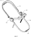
Fig. 2 is a perspective view of the child seat frame of the compact collapsible stroller of the present disclosure; -
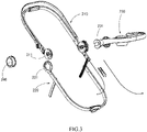
Fig. 3 is a perspective exploded view of the child seat frame of the compact collapsible stroller of the present disclosure; -
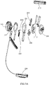
Fig. 3A is a perspective exploded view of some parts of the child seat frame of the compact collapsible stroller of the present disclosure; -
Fig. 4 is a side view of the compact collapsible stroller of the present disclosure, in which the child seat frame is in the seat mode; -
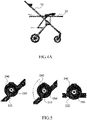
Fig. 4A is a side view of the compact collapsible stroller of the present disclosure, in which the child seat frame is in the cradle mode; -
Fig. 5 is a partial view of different modes of the child seat frame of the compact collapsible stroller of the present disclosure; -
Fig. 6 is a partial view of the child seat frame of the compact collapsible stroller in the seat mode of the present disclosure; -
Fig. 7 is a perspective exploded view of some parts of the child seat frame of the compact collapsible stroller of the present disclosure; -
Fig. 8 is a partial view of the child seat frame of the compact collapsible stroller in different states of the present disclosure; -
Fig. 9 is a side view of the child seat frame of the compact collapsible stroller in an unfolded and folded state of the present disclosure; -
Fig. 10 is a side view of the main stroller frame of the compact collapsible stroller of the present disclosure; -
Fig. 11 is a partial view of the main stroller frame of the compact collapsible stroller of the present disclosure, in which one side of the internal structure is exposed; -
Fig. 11A is a partial view of the main stroller frame of the compact collapsible stroller of the present disclosure, in which the other side of the internal structure is exposed; -
Fig. 12 is a view of the main stroller frame of the compact collapsible stroller in a folded state of the present disclosure; -
Fig. 13 is a schematic view showing a partial internal structure of the main stroller frame of the compact collapsible stroller of the present disclosure; -
Fig. 14 is a partial schematic view showing the main stroller frame of the compact collapsible stroller of the present disclosure, in which a part of the area is enlarged to show its structure more clearly; -
Fig. 15 is a partial view of the main stroller frame of the compact collapsible stroller of the present disclosure, in which one side of the internal structure is exposed; -
Fig. 16 is a partial side view of the compact collapsible stroller of the present disclosure; -
Fig. 16A is a side view of the compact collapsible stroller in a folded state of the present disclosure; -
Fig. 17 is a partial side view of the compact collapsible stroller of the present disclosure; -
Fig. 17A is a perspective view of the compact collapsible stroller in a folded state of the present disclosure; -
Fig. 18 is a perspective view of the child seat frame of the compact collapsible stroller of the present disclosure; -
Fig. 19 is a side view of the child seat frame of the compact collapsible stroller of the present disclosure; -
Fig. 20 is a side view of some parts of the child seat frame of the compact collapsible stroller of the present disclosure; -
Fig. 21 is a perspective view of some parts of the child seat frame of the compact collapsible stroller of the present disclosure; -
Fig. 22 is a perspective view of some parts of the child seat frame of the compact collapsible stroller of the present disclosure; -
Fig. 23 is a perspective view of some parts of the child seat frame of the compact collapsible stroller of the present disclosure; -
Fig. 24 is a side view of the child seat frame of the compact collapsible stroller of the present disclosure. -
- compact
collapsible stroller 1
main stroller frame 10- handle
portion 110- handle
portion plate 111 - spring
biased plunger 112 -
upper handle portion 113 - handle
portion hub 114
circular barrel 1141 -
lower handle portion 115
pivot point 1151 -
upper link 116 -
lower link 117
- handle
-
rear leg portion 120- rear
leg portion plate 121
lockingpin 1211 -
pivot point 122
- rear
-
front leg portion 130
frontleg portion plate 131 -
central frame hub 140 -
frame latch 150
extended latching surface 151 - link 160
-
adapter portion 170 -
rear wheels 180 - carrying
basket 190
- handle
-
child seat frame 20-
upper frame 210- upper
seat frame hub 211- ramped
surface 2111 -
spiral control surface 2112
- ramped
-
upper frame plunger 212 - fold
handle 213
- upper
-
lower frame 220- lower
seat frame hub 221 -
lower frame plunger 222
lower frameplunger control post 2221 - recline
handle 223
- lower
-
child tray 230
child tray hub 231 -
seat mount 240 - latch
pin assembly 250
rampedsurface 251
-
- In order to further illustrate the principle and structure of the present disclosure, the preferred embodiments of the present disclosure will be described in detail with reference to the accompanying drawings. However, the embodiments are only provided for illustration and explanation and cannot be used to limit the scope of patent protection of the present disclosure.
- The terms used in the present disclosure are only for the purpose of describing specific embodiments and are not intended to limit the present disclosure. The singular forms of "a", "said" and "the" used in the present disclosure and the appended claims are also intended to include plural forms, unless the context clearly indicates other meanings. It should also be understood that the term "and/or" used herein refers to and includes any or all possible combinations of one or more associated listed items.
- The compact collapsible stroller (hereinafter referred to as "stroller") 1 of the present disclosure includes a collapsible
main stroller frame 10, which can accommodate child seat frames 20 of various configurations (as shown inFig. 1 ). - One configuration of the
child seat frame 20 may include anupper frame 210, alower frame 220, achild tray 230, and a seat mount 240 (as shown inFig. 2 ). Theupper frame 210 and thelower frame 220 are pivotally connected to theseat mount 240 through an upperseat frame hub 211 and a lowerseat frame hub 221. Likewise, as shown inFigs. 3 and3A , thechild tray 230 is pivotally connected to the seat hub (seat mount) 240 through achild tray hub 231. - Referring to
Figs. 4 and4A , thechild seat frame 20 may have a seat mode and a cradle mode. One configuration for attaching thechild seat frame 20 to themain stroller frame 10 is in a forward sitting position, which is the seat mode. In the seat mode, theupper frame 210 may extend upward from theseat mount 240, specifically, obliquely extending backward and upward, and thelower frame 220 may extend downward from theseat mount 240, specifically, obliquely extending forward and downward. At this time, theupper frame 210 and thelower frame 220 are formed in a linear shape passing through theseat mount 240. In the cradle mode, theupper frame 210 and thelower frame 220 extend horizontally from theseat mount 240 to both sides thereof. Thechild seat frame 20 can be converted from the position shown inFig. 4 to a position where the cradle is lying down. - Referring to
Fig. 5 , in order to convert thechild seat frame 20 from the seat mode to the cradle position (i.e., cradle mode), the user may manipulate therecline handle 223, which uses a cable to retract the spring-loadedlower frame plunger 222 from a position engaging with theseat mount 240. This allows the entirechild seat frame 20 to rotate to a horizontal position relative to theseat mount 240, and re-engages the spring-loadedlower frame plunger 222 with theseat mount 240 to lock thechild seat frame 20 in this position. - Referring to
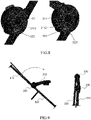
Fig. 6 , in addition to thereclining handle 223, thechild seat frame 20 also includes afold handle 213 for folding thechild seat frame 20 as a part of the folding of the stroller. The fold handle 213 retracts the spring-biasedupper frame plunger 212 from its engagement position with the lowerseat frame hub 221. The upper frame (i.e., upper seat frame) 210 can now rotate around theseat mount 240 relative to the lower frame (i.e., lower seat frame) 220. Referring toFig. 7 , when theupper frame 220 rotates, a rampedsurface 2111 in the upperseat frame hub 211 acts on a rampedsurface 251 on thelatch pin assembly 250 to press thelatch pin assembly 250 into theseat mount 240, and separate thelatch pin assembly 250 from thechild tray hub 231, thereby releasing thechild tray 230 to be able to pivot freely around theseat mount 240. In addition, referring toFig. 8 , aspiral control surface 2112 located in the upperseat frame hub 211 disengages the two lowerseat frame hubs 221 from theseat mount 240 because it acts on a lower frameplunger control post 2221. This allows thelower frame 220 to rotate around theseat mount 240 to a relatively vertical (upright) position with respect to theseat mount 240. Thespiral control surface 2112 is formed to gradually move away from the center of the upperseat frame hub 211 from one side to the other, so that when the upperseat frame hub 211 rotates relative to theseat mount 240, thespiral control surface 2112 may abut against and push the lower frameplunger control post 2221 to move away from theseat mount 240. Referring toFig. 9 , this operation causes theupper frame 210, thelower frame 220 and thechild tray 230 to fall parallel to one another and relatively vertical (upright) to theseat mount 240. - Referring to
Fig. 10 , the strollermain frame 10 may include ahandle portion 110, arear leg portion 120 and afront leg portion 130. Each part of the strollermain frame 10 is pivotally connected to acentral frame hub 140. An lower end of therear leg portion 120 hasrear wheels 180. An lower end of thefront leg portion 130 has front wheels. - Referring to
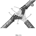
Figs. 11 and11A , aframe latch 150 pivotally connected to ahandle part plate 111 engages with alocking pin 1211 on the rearleg part plate 121 such that thestroller 1 is locked in the opened position. When theframe latch 150 is rotated so that the latch surface passes through thelock pin 1211 and is disengaged from thelock pin 1211, thehandle section plate 111 is allowed to rotate, and a frontleg section plate 131 is pulled by alink 160 to the folded position. Referring toFig. 12 , thehandle portion 110, therear leg portion 120, and thefront leg portion 130 are folded almost parallel to one anohter to obtain a compact folded size for easy transportation or storage of themain stroller frame 10 when the stroller is not in use. Referring toFig. 13 , the upper half of thehandle portion 110 is locked by a springbiased plunger 112 and thus cannot be rotated, the springbiased plunger 112 is pulled to an unlocked state by a cable anchored in a main folding release housing. In this way, theupper handle portion 113 and the parent bracket (the part extending horizontally from theupper handle portion 113 as shown inFig. 10 ) can be rotated in the folding process to obtain a more compact folding size. Referring toFig. 12 , thestroller 1 has a folding boundary (as shown by the dotted block inFig. 12 ) in the folding process. When thestroller 1 is transformed between the unfolded state and the folded state, none of the parts can exceed beyond the folding boundary. - Referring to
Fig. 13 , theupper handle portion 113 is pivotally fixed to thehandle portion hub 114. The springbiased plunger 112 is engaged with thehandle portion hub 114 so that theupper handle portion 113 cannot pivot relative to thehandle portion hub 114. The springbiased plunger 112 can be actuated via a cable to disengage from thehandle portion hub 114 so that theupper handle portion 113 can pivot relative to thehandle portion hub 114. - Referring to
Fig. 14 , the cable anchored on acircular barrel 1141 in thehandle portion hub 114 and attached to theframe latch 150 rotates with theupper handle portion 113, to actuate the frame latch 150 (an arrow inFig. 15 shows a direction in which theframe latch 150 is actuated) and pivot it past the locking pin, and thus fold thehandle portion 110 toward the closed position. Time for folding is controlled by anextended latch surface 151 of theframe latch 150. Theextended latch surface 151 allows theframe latch 150 to engage with thelocking pin 1211 until theupper handle portion 113 has rotated by a larger distance from its original position. When theextended latch surface 151 is disengaged from thelocking pin 1211, thehandle portion 110 may be folded toward the closed position. This results in a more natural folding movement while preventing themain stroller frame 10 from being accidentally folded (as shown inFig. 15 ). When theupper handle portion 113 rotates toward the opened position, an anchor end of the cable rotates backward (counterclockwisely as shown inFig. 13 ) along with theupper handle portion 113, and the length from the cable to theframe latch 150 increases, which allows theframe latch 150 to re-engage with thelocking pin 1211. - Referring to
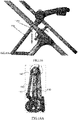
Fig.s 16 and 16A , the rotation of thelower handle portion 115 also drives a series of couplings between theseat mount 240 and the stroller basket for carrying the baby. Anupper link 116 is directly attached to the seat frame hub (seat mount) 240 and is connected to thehandle portion 110 at apivot point 1151. An upper end of theupper link 116 is formed with an adapter portion 170 (seeFig. 10 ). Due to the downward folding movement of thehandle portion 110, theupper link 116 is driven downward and the child seat hub (seat mount) 240 is pulled within a predetermined folding boundary. Referring toFigs. 17 and 17A , a basket frame is attached between alower link 117 and a pivot point on therear leg portion 120. A carryingbasket 190 may be provided below a basket frame (a left part of thelower link 117 as shown inFig. 10 ). During the folding of themain stroller frame 10, only the carryingbasket 190 is linked to themain stroller frame 10 to be folded, while theadapter portion 170 is not linked. Through the downward folding movement (pivoting movement) of thehandle portion 110, theupper link 116 drives thelower link 117 in a downward movement, and further drives the basket frame downward and rotates it behind therear leg portion 120. This allows the basket frame to be installed within the folding boundary while maximizing its size so as to achieve maximum storage capacity. - When the
stroller 1 is transformed from the unfolded state (shown inFigs. 16 and17 ) to the folded state (shown inFigs. 16A and17A ), theseat mount 240 gradually approaches thecentral frame hub 140, and finally overlaps or at least substantially overlaps in a transverse direction (perpendicular to the paper surface ofFig. 16A ). At this time, thehandle portion 110, therear leg portion 120, and thefront leg portion 130 vertically extend substantially downward from thecentral frame hub 140, and theupper frame 210, thelower frame 220, and thechild tray 230 vertically extend substantially downward from theseat mount 240, so that thestroller 1 in the folded state occupies the minimum space. - Other embodiments of the invention will be apparent to those skilled in the art from consideration of the specification and practice of the invention disclosed here. This application is intended to cover any variations, uses, or adaptations of the invention following the general principles thereof and including such departures from the present disclosure as come within known or customary practice in the art. It is intended that the specification and examples be considered as exemplary only, with a true scope and spirit of the invention being indicated by the following claims.
- Although the present disclosure has been described with reference to the exemplary embodiments, the terms used are illustrative and exemplary rather than restrictive. Since the present disclosure can be implemented in various forms without departing from the spirit and essence of the present disclosure, it should be understood that the foregoing embodiments are not limited to any of the foregoing details, but should be interpreted in the broadest sense within the scope defined by the claims. Therefore, all changes falling within the scope of the claims or their equivalents shall be covered by the claims.
Claims (10)
- A compact collapsible stroller (1), characterized in that the compact collapsible stroller comprises a main stroller frame (10) which includes a central frame hub (140) and a handle portion (110), a rear leg portion (120), and a front leg portion (130) pivotally coupled to the central frame hub, and the main stroller frame further comprises an adapter portion (170) attached to the handle portion (110), and
the compact collapsible stroller has an unfolded state for use and a folded state for storage, wherein the adapter portion (170) approaches rear wheels (180) when the compact collapsible stroller is transformed from an unfolded state to a folded state,. - The compact collapsible stroller according to claim 1, characterized in that in the folded state, the central frame hub and a seat mount overlap in a lateral direction.
- The compact collapsible stroller of claim 1, characterized in that in the folded state, each of the handle portion, the rear leg portion, and the front leg portion substantially vertically extends downward from the central frame hub, and each of an upper frame, a lower frame and a child tray substantially vertically extends downward from the seat mount.
- The compact collapsible stroller of claim 1, characterized in that the handle portion comprises:a lower handle portion (115) pivotally coupled to the central frame hub;a handle portion hub (114) formed at an end of the lower handle portion opposite to the central frame hub;an upper handle portion (113) pivotally coupled to the handle portion hub.
- The compact collapsible stroller according to claim 4, characterized in that the rotation of the upper handle portion is capable of disengaging the lower handle portion from the central frame hub, so that the lower handle portion can rotate relative to the central frame hub.
- The compact collapsible stroller of claim 5, characterized in that the rotation of the lower handle portion relative to the central frame hub causes the seat mount to approach the central frame hub.
- The compact collapsible stroller according to claim 1, characterized in that the main stroller frame further comprises a carrying basket (190) extending backward from the rear leg portion (120), and the carrying basket (190) rotates and simultaneously moves close to the rear leg portion (120) when the compact collapsible stroller is transformed from the unfolded state to the folded state.
- The compact collapsible stroller of claim 7, characterized in that the main stroller frame further comprises:an upper link (116) attached to the adapter portion (170) and pivotally connected to the handle portion;a lower link (117) pivotally connected to the rear leg portion and the upper link.
- The compact collapsible stroller of claim 8, characterized in that the compact collapsible stroller further comprises a basket frame attached between the lower link and a pivot point on the rear leg portion.
- The compact collapsible stroller according to claim 9, characterized in that when transforming from the unfolded state to the folded state, through the downward pivoting movement of the handle portion, the upper link drives the lower link in a downward movement, thereby driving the basket frame attached to the lower link to rotate corresponding to the pivot point on the rear leg portion.
Applications Claiming Priority (2)
| Application Number | Priority Date | Filing Date | Title |
|---|---|---|---|
| US201962941303P | 2019-11-27 | 2019-11-27 | |
| PCT/IB2020/061216 WO2021105944A1 (en) | 2019-11-27 | 2020-11-27 | Compact foldable stroller |
Publications (1)
| Publication Number | Publication Date |
|---|---|
| EP4067206A1 true EP4067206A1 (en) | 2022-10-05 |
Family
ID=73598873
Family Applications (5)
| Application Number | Title | Priority Date | Filing Date |
|---|---|---|---|
| EP24159170.0A Pending EP4371850A1 (en) | 2019-11-27 | 2020-11-26 | Child stroller apparatus |
| EP20815785.9A Active EP4065449B1 (en) | 2019-11-27 | 2020-11-26 | Child stroller apparatus |
| EP25161019.2A Pending EP4538147A3 (en) | 2019-11-27 | 2020-11-27 | Child seat frame and compact collapsible stroller |
| EP20839141.7A Pending EP4067206A1 (en) | 2019-11-27 | 2020-11-27 | Compact foldable stroller |
| EP20841758.4A Active EP4067207B1 (en) | 2019-11-27 | 2020-11-27 | Child seat frame and compact foldable stroller |
Family Applications Before (3)
| Application Number | Title | Priority Date | Filing Date |
|---|---|---|---|
| EP24159170.0A Pending EP4371850A1 (en) | 2019-11-27 | 2020-11-26 | Child stroller apparatus |
| EP20815785.9A Active EP4065449B1 (en) | 2019-11-27 | 2020-11-26 | Child stroller apparatus |
| EP25161019.2A Pending EP4538147A3 (en) | 2019-11-27 | 2020-11-27 | Child seat frame and compact collapsible stroller |
Family Applications After (1)
| Application Number | Title | Priority Date | Filing Date |
|---|---|---|---|
| EP20841758.4A Active EP4067207B1 (en) | 2019-11-27 | 2020-11-27 | Child seat frame and compact foldable stroller |
Country Status (10)
| Country | Link |
|---|---|
| US (4) | US12179826B2 (en) |
| EP (5) | EP4371850A1 (en) |
| JP (3) | JP7668275B2 (en) |
| KR (2) | KR102837648B1 (en) |
| CN (2) | CN112849253A (en) |
| AU (1) | AU2020391923B2 (en) |
| CA (3) | CA3154263A1 (en) |
| ES (2) | ES2983237T3 (en) |
| TW (6) | TW202604768A (en) |
| WO (3) | WO2021105286A1 (en) |
Families Citing this family (5)
| Publication number | Priority date | Publication date | Assignee | Title |
|---|---|---|---|---|
| CN112678059B (en) * | 2019-10-17 | 2023-06-30 | 明门瑞士股份有限公司 | Baby carriage and synchronous folding mechanism thereof |
| TW202604768A (en) | 2019-11-27 | 2026-02-01 | 瑞士商明門瑞士股份有限公司 | Child stroller apparatus |
| TWI857348B (en) * | 2021-09-16 | 2024-10-01 | 瑞士商明門瑞士股份有限公司 | Baby carriage |
| CN217918069U (en) * | 2022-05-20 | 2022-11-29 | 宁波妈咪宝婴童用品制造有限公司 | Pushable and pullable baby carriage |
| CN218106691U (en) * | 2022-05-20 | 2022-12-23 | 宁波稳泰运动器材有限公司 | Golf cart |
Citations (4)
| Publication number | Priority date | Publication date | Assignee | Title |
|---|---|---|---|---|
| EP1735200B1 (en) * | 2004-04-13 | 2011-01-19 | Graco Children's Products Inc. | Foldable stroller |
| DE102017109236A1 (en) * | 2016-04-29 | 2017-11-02 | Wonderland Switzerland Ag | STROLLER DEVICE |
| EP3484758A1 (en) * | 2016-07-12 | 2019-05-22 | Larktale Pty Ltd | Z-foldable stroller and accessories |
| EP2611670B1 (en) * | 2010-09-01 | 2020-04-22 | Britax Childcare Pty Ltd. | Folding stroller improvements |
Family Cites Families (90)
| Publication number | Priority date | Publication date | Assignee | Title |
|---|---|---|---|---|
| US3556546A (en) | 1967-08-21 | 1971-01-19 | Herschall F Garhan | Baby strollers |
| US3459435A (en) | 1967-08-21 | 1969-08-05 | Herschal F Garhan | Baby strollers |
| IT7420617U1 (en) | 1974-01-25 | 1975-07-25 | Perego Pines Spa | Baby stroller, easily foldable and carryable on the arm |
| US6102431A (en) | 1998-06-01 | 2000-08-15 | Hood Technology Corporation | Collapsible baby stroller and releasable locking and folding mechanism therefor |
| US6523853B1 (en) | 2001-11-05 | 2003-02-25 | Kenny Cheng | Safe folding device for a foldable stroller |
| GB2419520B (en) | 2004-09-28 | 2008-04-09 | Armon Ltd | Convertible seat for a baby buggy |
| GB0422967D0 (en) * | 2004-10-15 | 2004-11-17 | Derek Bull Associates Ltd | Folding wheeled chair |
| US7255206B1 (en) | 2005-03-05 | 2007-08-14 | Hackbarth Christina L | Shopping cart brake |
| TWM288269U (en) * | 2005-09-29 | 2006-03-01 | Link Treasure Ltd | One-hand controlled seat inclination structure for baby trolley |
| TWM295071U (en) | 2006-01-18 | 2006-08-01 | Link Treasure Ltd | Joint structure for baby stroller |
| US7267359B1 (en) * | 2006-06-08 | 2007-09-11 | Link Treasure Limited | Collapsible stroller frame |
| DE202006012430U1 (en) | 2006-08-11 | 2006-10-12 | Hauck Gmbh & Co. Kg | Chassis for pushchair or buggy has unit for adjusting height of connecting device for shell or seat formed by vertically extending guide tubes installed on sides of frame, and inner tubes movable and lockable in guide tubes |
| US8485546B2 (en) | 2006-09-08 | 2013-07-16 | Lerado (Zhong Shan) Industrial Co., Ltd. | Foldable baby stroller frame |
| TWM325960U (en) * | 2006-09-29 | 2008-01-21 | Golden Point Marketing Ltd | Folding control mechanism for baby stroller |
| US8087689B2 (en) | 2008-07-31 | 2012-01-03 | Cosco Management, Inc. | Compact collapsible stroller |
| GB0818605D0 (en) | 2008-10-10 | 2008-11-19 | Scs London Ltd | Apparatus and method |
| US8474854B2 (en) * | 2009-03-24 | 2013-07-02 | Graco Children's Products Inc. | Foldable stroller and fold interlock mechanism |
| US8764048B1 (en) * | 2009-01-08 | 2014-07-01 | Graco Children's Products Inc. | Foldable, removable, reversible stroller seat |
| CN101837799A (en) * | 2009-03-13 | 2010-09-22 | 葛莱儿婴儿产品股份有限公司 | Stroller and seat assembly |
| US8714581B2 (en) | 2010-01-25 | 2014-05-06 | Cosco Management, Inc. | Compact foldable stroller |
| CN201769848U (en) | 2010-05-20 | 2011-03-23 | 刘修平 | Baby carriage folded by one hand |
| CN202557593U (en) * | 2011-04-26 | 2012-11-28 | 克斯克管理公司 | Transport equipment for children |
| US20130113185A1 (en) | 2011-11-07 | 2013-05-09 | Dynamic Brands, Llc | Baby stroller |
| GB2496225A (en) | 2011-11-07 | 2013-05-08 | Unique Product & Design Co Ltd | A stroller with a folding and rotatable seat |
| US8596669B2 (en) | 2011-11-07 | 2013-12-03 | Unique Product & Design Co., Ltd. | Baby stroller |
| US9050993B2 (en) | 2012-02-02 | 2015-06-09 | Graco Children's Products Inc. | Foldable stroller and automatic folding tray for same |
| CN103318242B (en) | 2012-03-19 | 2015-11-25 | 珠海优力创工贸有限公司 | There is the folded perambulator at commutation seat |
| DE102013005495B4 (en) * | 2012-03-29 | 2022-05-05 | Wonderland Nurserygoods Company Limited | prams and pram frames |
| CN103373382B (en) * | 2012-04-20 | 2015-11-25 | 珠海优力创工贸有限公司 | Commutation seat and the folded perambulator with commutation seat |
| NO335333B1 (en) * | 2012-09-19 | 2014-11-17 | Stokke As | Stroller |
| US9399477B2 (en) * | 2012-12-27 | 2016-07-26 | Kolcraft Enterprises, Inc. | Strollers with removable child supports and related methods |
| US8882134B2 (en) | 2013-01-07 | 2014-11-11 | Kolcraft Enterprises, Inc. | Maneuverable strollers |
| EP2832624A4 (en) | 2013-01-28 | 2016-02-10 | Unitron Entpr Zhuhai Co Ltd | Folding joint for baby carriage |
| US9221487B2 (en) | 2013-04-30 | 2015-12-29 | Graco Children's Products Inc. | Convertible stroller seat |
| CN203318470U (en) * | 2013-05-09 | 2013-12-04 | 中山市隆成日用制品有限公司 | Baby carriage framework joint |
| CN203427850U (en) * | 2013-07-05 | 2014-02-12 | 中山市隆成日用制品有限公司 | Release mechanism of folding joints of baby carriage |
| US9108659B2 (en) * | 2013-08-07 | 2015-08-18 | Recaro Child Safety Llc | Stroller with selectively hidden adapters |
| CN203558113U (en) | 2013-10-17 | 2014-04-23 | 欧仕儿童用品(福建)有限公司 | Quick-fold children's frame |
| US20150183450A1 (en) | 2013-12-31 | 2015-07-02 | Way-Hong Chen | Baby Stroller Shopping Cart |
| CN203996350U (en) | 2014-01-10 | 2014-12-10 | 克斯克管理公司 | Foldable go-cart |
| US9463822B2 (en) | 2014-01-10 | 2016-10-11 | Dorel Juvenile Group, Inc. | Stroller |
| CN204641848U (en) | 2014-04-10 | 2015-09-16 | 明门(中国)幼童用品有限公司 | Stroller Standing Units & Strollers |
| CN204137084U (en) * | 2014-05-29 | 2015-02-04 | 珠海优力创工贸有限公司 | For hinge and the collapsible stroller of go-cart |
| ES2663808T3 (en) | 2014-06-30 | 2018-04-17 | Wonderland Switzerland Ag | Pram for child |
| AU2015293596B2 (en) | 2014-07-23 | 2019-07-11 | Endepro Gmbh | Baby carriage |
| WO2016025690A1 (en) | 2014-08-14 | 2016-02-18 | Baby Jogger, LLC | Baby stroller |
| CN105564489B (en) | 2014-10-10 | 2018-04-13 | 明门香港股份有限公司 | Baby bearing device and baby stroller |
| CN105984481B (en) * | 2015-02-11 | 2018-05-04 | 明门香港股份有限公司 | Baby carriage frame |
| CN106184331B (en) | 2015-04-29 | 2018-07-06 | 珠海阳光儿童用品有限公司 | Infant car seat chair frame and perambulator |
| US9908551B2 (en) * | 2015-09-02 | 2018-03-06 | Artsana USA, Inc | Travel stroller folding and latch mechanism |
| GB2545783B (en) | 2015-11-23 | 2019-04-10 | Wonderland Switzerland Ag | Infant stroller apparatus |
| CN106741091B (en) | 2015-11-23 | 2019-04-02 | 明门香港股份有限公司 | Baby carriage |
| CN105539557B (en) | 2016-02-03 | 2018-08-10 | 广东乐美达集团有限公司 | A kind of perambulator that linkage folds |
| US10077063B2 (en) | 2016-02-03 | 2018-09-18 | Wonderland Switzerland Ag | Child stroller apparatus having an expandable frame |
| CN107235062B (en) * | 2016-03-29 | 2019-07-09 | 明门香港股份有限公司 | baby carriage |
| CN107284506B (en) | 2016-04-13 | 2019-11-19 | 明门香港股份有限公司 | Folding seat group and stroller |
| CN110254493B (en) * | 2016-04-29 | 2022-02-11 | 明门瑞士股份有限公司 | Strollers and child seats removably mounted on strollers |
| US20200172142A1 (en) | 2016-07-12 | 2020-06-04 | Dynamic Motion, Llc | Z-foldable stroller and accessories |
| CN206384007U (en) | 2016-11-22 | 2017-08-08 | 明门瑞士股份有限公司 | Collapsible stroller apparatus |
| FR3059968B1 (en) | 2016-12-13 | 2019-05-24 | Dorel France | CONVERTIBLE SUPPORT BETWEEN AN EXTENDED POSITION AND AT LEAST ONE SITUATED POSITION FOR CHILDREN'S STROLLER AND CORRESPONDING STROLLER |
| CN113104094B (en) * | 2017-01-06 | 2023-09-22 | 明门瑞士股份有限公司 | Stroller frame with dinner plate |
| US9962011B1 (en) | 2017-01-27 | 2018-05-08 | Kolcraft Enterprises, Inc. | Recline assemblies for stroller seats |
| EP3363711A1 (en) * | 2017-02-14 | 2018-08-22 | Dorel France | Child's pushchair comprising a removable booster seat, and corresponding booster seat |
| CA3115901A1 (en) * | 2017-04-26 | 2018-10-26 | Wonderland Switzerland Ag | Child stroller apparatus |
| CN108860279B (en) * | 2017-05-15 | 2021-01-29 | 明门瑞士股份有限公司 | Baby carriage and folding mechanism thereof |
| CN206885123U (en) | 2017-05-19 | 2018-01-16 | 东莞硕仕儿童用品有限公司 | A kind of folding baby stroller |
| CN107264600A (en) | 2017-06-01 | 2017-10-20 | 好孩子儿童用品有限公司 | A kind of children trolley |
| US10858030B2 (en) | 2017-07-18 | 2020-12-08 | Wonderland Switzerland Ag | Baby carrier with a convertible seat frame |
| CN207360393U (en) | 2017-08-31 | 2018-05-15 | 昆山威凯儿童用品有限公司 | A kind of foldable baby cart |
| US10449987B2 (en) * | 2018-01-17 | 2019-10-22 | Evenflo Company, Inc. | Tandem stroller with sliding carriage |
| US20200391781A1 (en) | 2018-03-07 | 2020-12-17 | Zhongshan Kingmoon Children Products Co. Ltd. | Stroller |
| US10766517B2 (en) | 2018-03-16 | 2020-09-08 | Strova, Inc. | Stroller assembly |
| KR101894460B1 (en) * | 2018-04-10 | 2018-09-04 | 김미진 | Baby carriage with improved ease of use |
| DE102019207407A1 (en) | 2018-05-21 | 2019-11-21 | Wonderland Switzerland Ag | CHILDREN CARRIAGE, SIMPLY AND COMPACTLY COLLAPSIBLE |
| CN209079968U (en) * | 2018-09-19 | 2019-07-09 | 明门瑞士股份有限公司 | Chair angle adjustment mechanism |
| CN209208837U (en) * | 2018-10-30 | 2019-08-06 | 明门(中国)幼童用品有限公司 | Closing-folding mechanism and its child carrier |
| CN115675609A (en) * | 2019-01-08 | 2023-02-03 | 明门瑞士股份有限公司 | stroller frame |
| CN209535175U (en) * | 2019-01-15 | 2019-10-25 | 徐江林 | A folding stroller |
| CN111483503B (en) | 2019-01-29 | 2022-07-19 | 明门(中国)幼童用品有限公司 | Pivoting seat mechanism and child stroller comprising same |
| CN111483508B (en) * | 2019-01-29 | 2022-09-13 | 明门瑞士股份有限公司 | Baby carriage and baby carriage carrier conversion mechanism thereof |
| CN115583281A (en) | 2019-05-07 | 2023-01-10 | 明门瑞士股份有限公司 | multi-seater baby stroller |
| CN111907583A (en) | 2019-05-09 | 2020-11-10 | 明门瑞士股份有限公司 | Child seat and foldable baby carriage thereof |
| US11390311B2 (en) | 2019-05-09 | 2022-07-19 | Wonderland Switzerland Ag | Child stroller apparatus |
| CN112550419B (en) | 2019-09-26 | 2023-03-31 | 明门瑞士股份有限公司 | Handrail folding mechanism and baby carriage with same |
| CN112678059B (en) | 2019-10-17 | 2023-06-30 | 明门瑞士股份有限公司 | Baby carriage and synchronous folding mechanism thereof |
| US11136055B2 (en) | 2019-11-04 | 2021-10-05 | Dynamic Motion, Llc | Foldable stroller |
| TW202604768A (en) * | 2019-11-27 | 2026-02-01 | 瑞士商明門瑞士股份有限公司 | Child stroller apparatus |
| WO2021247472A1 (en) * | 2020-06-01 | 2021-12-09 | Horst Andrew J | Compact foldable stroller |
| US12594979B2 (en) | 2021-09-13 | 2026-04-07 | Artsana Usa, Inc. | Folding stroller adaptable for single or double occupants |
| CN116101353B (en) * | 2021-11-10 | 2025-09-05 | 明门瑞士股份有限公司 | Baby carrier |
-
2020
- 2020-11-26 TW TW114137065A patent/TW202604768A/en unknown
- 2020-11-26 AU AU2020391923A patent/AU2020391923B2/en active Active
- 2020-11-26 TW TW111126260A patent/TWI862950B/en active
- 2020-11-26 TW TW109141596A patent/TWI774139B/en active
- 2020-11-26 ES ES20815785T patent/ES2983237T3/en active Active
- 2020-11-26 EP EP24159170.0A patent/EP4371850A1/en active Pending
- 2020-11-26 TW TW113139461A patent/TWI903813B/en active
- 2020-11-26 WO PCT/EP2020/083512 patent/WO2021105286A1/en not_active Ceased
- 2020-11-26 KR KR1020227014507A patent/KR102837648B1/en active Active
- 2020-11-26 KR KR1020257024271A patent/KR20250114560A/en active Pending
- 2020-11-26 EP EP20815785.9A patent/EP4065449B1/en active Active
- 2020-11-26 CA CA3154263A patent/CA3154263A1/en active Pending
- 2020-11-26 JP JP2022529890A patent/JP7668275B2/en active Active
- 2020-11-27 US US17/756,575 patent/US12179826B2/en active Active
- 2020-11-27 EP EP25161019.2A patent/EP4538147A3/en active Pending
- 2020-11-27 WO PCT/IB2020/061218 patent/WO2021105945A1/en not_active Ceased
- 2020-11-27 US US17/756,454 patent/US12246768B2/en active Active
- 2020-11-27 EP EP20839141.7A patent/EP4067206A1/en active Pending
- 2020-11-27 CA CA3159712A patent/CA3159712A1/en active Pending
- 2020-11-27 ES ES20841758T patent/ES3040718T3/en active Active
- 2020-11-27 TW TW109141883A patent/TWI759982B/en active
- 2020-11-27 CA CA3159312A patent/CA3159312A1/en active Pending
- 2020-11-27 CN CN202011363386.4A patent/CN112849253A/en active Pending
- 2020-11-27 EP EP20841758.4A patent/EP4067207B1/en active Active
- 2020-11-27 TW TW109141902A patent/TWI759983B/en active
- 2020-11-27 WO PCT/IB2020/061216 patent/WO2021105944A1/en not_active Ceased
- 2020-11-27 CN CN202011358282.4A patent/CN112849252A/en active Pending
-
2024
- 2024-07-05 JP JP2024108937A patent/JP7791255B2/en active Active
- 2024-10-24 US US18/926,217 patent/US20250050933A1/en active Pending
-
2025
- 2025-01-28 US US19/038,869 patent/US20250269893A1/en active Pending
- 2025-10-22 JP JP2025177812A patent/JP2026021366A/en active Pending
Patent Citations (4)
| Publication number | Priority date | Publication date | Assignee | Title |
|---|---|---|---|---|
| EP1735200B1 (en) * | 2004-04-13 | 2011-01-19 | Graco Children's Products Inc. | Foldable stroller |
| EP2611670B1 (en) * | 2010-09-01 | 2020-04-22 | Britax Childcare Pty Ltd. | Folding stroller improvements |
| DE102017109236A1 (en) * | 2016-04-29 | 2017-11-02 | Wonderland Switzerland Ag | STROLLER DEVICE |
| EP3484758A1 (en) * | 2016-07-12 | 2019-05-22 | Larktale Pty Ltd | Z-foldable stroller and accessories |
Non-Patent Citations (1)
| Title |
|---|
| See also references of WO2021105944A1 * |
Also Published As
Similar Documents
| Publication | Publication Date | Title |
|---|---|---|
| US12246768B2 (en) | Compact collapsible stroller | |
| US8764048B1 (en) | Foldable, removable, reversible stroller seat | |
| US8282120B2 (en) | Foldable stroller | |
| CN104340257B (en) | Child support apparatus | |
| US20070001429A1 (en) | Stroller seat attachment | |
| US8727370B2 (en) | Foldable stroller with rotatable leg rest adapted for receiving a car seat | |
| US8585063B2 (en) | Child carrier apparatus and its operating method | |
| CA3030578A1 (en) | Z-foldable stroller and accessories | |
| CN221852005U (en) | Foldable carrier and child carrier | |
| TWI891006B (en) | Limiting device and child carrier | |
| CN109774772B (en) | A baby carriage | |
| CN111791765A (en) | child safety seat |
Legal Events
| Date | Code | Title | Description |
|---|---|---|---|
| STAA | Information on the status of an ep patent application or granted ep patent |
Free format text: STATUS: UNKNOWN |
|
| STAA | Information on the status of an ep patent application or granted ep patent |
Free format text: STATUS: THE INTERNATIONAL PUBLICATION HAS BEEN MADE |
|
| PUAI | Public reference made under article 153(3) epc to a published international application that has entered the european phase |
Free format text: ORIGINAL CODE: 0009012 |
|
| STAA | Information on the status of an ep patent application or granted ep patent |
Free format text: STATUS: REQUEST FOR EXAMINATION WAS MADE |
|
| 17P | Request for examination filed |
Effective date: 20220603 |
|
| AK | Designated contracting states |
Kind code of ref document: A1 Designated state(s): AL AT BE BG CH CY CZ DE DK EE ES FI FR GB GR HR HU IE IS IT LI LT LU LV MC MK MT NL NO PL PT RO RS SE SI SK SM TR |
|
| DAV | Request for validation of the european patent (deleted) | ||
| DAX | Request for extension of the european patent (deleted) | ||
| STAA | Information on the status of an ep patent application or granted ep patent |
Free format text: STATUS: EXAMINATION IS IN PROGRESS |
|
| 17Q | First examination report despatched |
Effective date: 20230727 |
|
| TPAC | Observations filed by third parties |
Free format text: ORIGINAL CODE: EPIDOSNTIPA |