EP4067170A1 - A motor vehicle - Google Patents
A motor vehicle Download PDFInfo
- Publication number
- EP4067170A1 EP4067170A1 EP22166323.0A EP22166323A EP4067170A1 EP 4067170 A1 EP4067170 A1 EP 4067170A1 EP 22166323 A EP22166323 A EP 22166323A EP 4067170 A1 EP4067170 A1 EP 4067170A1
- Authority
- EP
- European Patent Office
- Prior art keywords
- clip
- trim
- mutually opposite
- motor vehicle
- add
- Prior art date
- Legal status (The legal status is an assumption and is not a legal conclusion. Google has not performed a legal analysis and makes no representation as to the accuracy of the status listed.)
- Granted
Links
Images


Classifications
-
- B—PERFORMING OPERATIONS; TRANSPORTING
- B60—VEHICLES IN GENERAL
- B60R—VEHICLES, VEHICLE FITTINGS, OR VEHICLE PARTS, NOT OTHERWISE PROVIDED FOR
- B60R11/00—Arrangements for holding or mounting articles, not otherwise provided for
- B60R11/04—Mounting of cameras operative during drive; Arrangement of controls thereof relative to the vehicle
-
- B—PERFORMING OPERATIONS; TRANSPORTING
- B60—VEHICLES IN GENERAL
- B60R—VEHICLES, VEHICLE FITTINGS, OR VEHICLE PARTS, NOT OTHERWISE PROVIDED FOR
- B60R11/00—Arrangements for holding or mounting articles, not otherwise provided for
- B60R2011/0001—Arrangements for holding or mounting articles, not otherwise provided for characterised by position
- B60R2011/0003—Arrangements for holding or mounting articles, not otherwise provided for characterised by position inside the vehicle
- B60R2011/0019—Side or rear panels
- B60R2011/0022—Pillars
-
- B—PERFORMING OPERATIONS; TRANSPORTING
- B60—VEHICLES IN GENERAL
- B60R—VEHICLES, VEHICLE FITTINGS, OR VEHICLE PARTS, NOT OTHERWISE PROVIDED FOR
- B60R11/00—Arrangements for holding or mounting articles, not otherwise provided for
- B60R2011/0001—Arrangements for holding or mounting articles, not otherwise provided for characterised by position
- B60R2011/004—Arrangements for holding or mounting articles, not otherwise provided for characterised by position outside the vehicle
-
- B—PERFORMING OPERATIONS; TRANSPORTING
- B60—VEHICLES IN GENERAL
- B60R—VEHICLES, VEHICLE FITTINGS, OR VEHICLE PARTS, NOT OTHERWISE PROVIDED FOR
- B60R11/00—Arrangements for holding or mounting articles, not otherwise provided for
- B60R2011/0042—Arrangements for holding or mounting articles, not otherwise provided for characterised by mounting means
- B60R2011/0049—Arrangements for holding or mounting articles, not otherwise provided for characterised by mounting means for non integrated articles
- B60R2011/005—Connection with the vehicle part
- B60R2011/0059—Connection with the vehicle part using clips, clamps, straps or the like
Definitions
- the invention relates to motor vehicle comprising an add-on part and a carrier part, the add-on part being attached to the carrier part, the add-on part comprising two mutually opposite clip towers onto each of which a trim clip is provided and a cable, a wiring harness or the like, each trim clip having a first side part and a second side part, with regard to the clip tower a trim clip is provided on the first side part of the trim clip being positioned opposite the second side part of the trim clip, the carrier part comprising a receiving aperture for receiving a clip tower with the trim clip and a functional hole for passing through the cable, the wiring harness or the like.
- the add-on part comprises retention clips mounted on two mutually opposite clip towers.
- the carrier part comprises two receiving slots each for receiving a respective clip tower with its trim clip and an additional hole, also called a functional hole, for providing passage of the cable, the wiring harness or the like.
- this object is at least partly achieved by providing a motor vehicle comprising an add-on part and a carrier part, the add-on part being attached to the carrier part, the add-on part comprising two mutually opposite clip towers onto each of which a trim clip is provided and a cable, a wiring harness or the like, each trim clip having a first side part and a second side part, with regard to the clip tower a trim clip is provided on the first side part of the trim clip being positioned opposite the second side part of the trim clip, the carrier part comprising a receiving aperture for receiving a clip tower with the trim clip and a functional hole for passing through the cable, the wiring harness or the like, characterized in that the carrier part comprises a single aperture for receiving both the two mutually opposite clip towers with the trim clips and for passing through the cable, the wiring harness or the like.
- the attachment of the add-on part to the carrier part only requires a limited foot print while still being able to provide a robust attachment.
- the material usage can be minimized by minimizing material overlap of the two components, i.e. the add-on part and the carrier part.
- the single aperture can be rectangular, trapezial or any other shape with two mutually opposite edges for providing engagement for the trim clips.
- the single aperture is defined by two mutually opposite aperture engaging edges and by two mutually opposite aperture side edges, wherein the first side parts of the trim clips face each other, wherein one of the two mutually opposite engaging edges is engaged only by the second side part of the trim clip of one of the mutually opposite clip towers and wherein the other one of the two mutually opposite engaging edges being engaged only by the second side part of the trim clip of the other of the mutually opposite clip towers.
- the one of the two mutually opposite aperture engaging edges is larger than the other one of the two mutually opposite aperture engaging edges.
- the single aperture has a larger dimension at the side of the one of the two mutually opposite aperture engaging edges, which can provide sufficient room for passage of the cable, the wiring harness or the like.
- sufficient room for passing through of the cable, the wiring harness or the like can be realized by one or two outwardly curved aperture side edges.
- the add-on part comprises at least one rib positioned for engaging the first side part of one of the trim clips.
- the ribs prevent unwanted loosening of the add-on part from the carrier part in case the motor vehicle experiences larges forces, such as when driving over a very bumpy road.
- the add-on part comprises two mutually opposite flanges interconnecting end sides of the two mutually opposite clip towers. In this manner inwards bending of the clip towers during assembly and during use is prevented, providing a robust attachment over time.
- the motor vehicle comprises a driver cabin having an A-pillar, the A-pillar comprising the carrier part.
- the add-on part is an electronic unit, such as an electronic blind spot object detection unit.
- An A-pillar of a driver cabin is nowadays more frequently used for attachment of components such as mirrors and electronic detection units, in particular an electronic blind spot object detection unit. Since the A-pillar has a relatively small width the present invention provides the possibility of attaching an add-on part, such as an electronic blind spot object detection unit, to a carrier part provided on the A-pillar in a robust manner.
- the invention is not limited to attachment of an add-on part to a carrier part of an A-pillar, but that the invention is also applicable to add-on parts attached to carrier parts provided on other parts of the vehicle, such as a B-pillar, a dashboard or a vehicle panel, and the like.
- FIGs. 1 and 2 one of two mutually opposite clip towers 1 with a trim clip 2 of an add-on part 3 and a carrier part 4 with two receiving slots 5, 6 and a functional hole 7 of a known motor vehicle are shown, respectively.
- the add-on part 3 comprises two of such clip towers 1 and a cable 8 for example for power supply or signal transmission.
- the add-on part according to the invention can also be provided with a wiring harness or the like. Attachment of the add-on part 3 to the carrier part 4 is accomplished by pushing the clip towers 1 in the two receiving slots 5, 6 and by passing the cable 8 through the functional hole 7.
- FIG 3 an embodiment of a carrier part 14 comprising a single aperture 15 for receiving both the two mutually opposite clip towers 11, 12 with their metallic trim clips 16, 17 and the cable 18 of the add-on part 13 is shown schematically.
- the single aperture 15 is defined by two mutually opposite aperture engaging edges 19, 20 and by two mutually opposite aperture side edges 21, 22.
- first side parts 16A, 17A of the metallic trim clips 16, 17 face each other.
- the engaging edge 19 is engaged only by the second side part 16B of the metallic trim clip 16 and other engaging edge 20 is engaged only by the second side part 17B of the metallic trim clip 17.
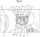
- the aperture engaging edge 19 is larger than the aperture engaging edge 20 so that sufficient space is provided for the cable 18 to pass through the single aperture 15 as is shown in Figure 6 .
- the add-on part 13 further comprises two mutually opposite flanges 23, 24 interconnecting end sides of the two mutually opposite clip towers 11, 12 to prevent inward bending of the clip towers 11, 12.
- the add-on part 13 comprises ribs 25, 26 positioned for engaging the first side parts 16A, 17A of the metallic trim clips 16, 17 to increase the clipping force.
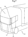
- a heavy goods vehicle 30 comprising a driver cabin 31 with an A-pillar 32.
- the A-pillar comprising a carrier part 14 to which an electronic unit, in this example an electronic blind spot object detection unit 33 as add-on part is attached.
- an electronic unit in this example an electronic blind spot object detection unit 33 as add-on part is attached.
Landscapes
- Engineering & Computer Science (AREA)
- Mechanical Engineering (AREA)
- Installation Of Indoor Wiring (AREA)
- Vehicle Interior And Exterior Ornaments, Soundproofing, And Insulation (AREA)
Abstract
Description
- The invention relates to motor vehicle comprising an add-on part and a carrier part, the add-on part being attached to the carrier part, the add-on part comprising two mutually opposite clip towers onto each of which a trim clip is provided and a cable, a wiring harness or the like, each trim clip having a first side part and a second side part, with regard to the clip tower a trim clip is provided on the first side part of the trim clip being positioned opposite the second side part of the trim clip, the carrier part comprising a receiving aperture for receiving a clip tower with the trim clip and a functional hole for passing through the cable, the wiring harness or the like.
- It is known to mount an add-on part such as an interior components of motor vehicles, e.g. a dashboard component, to a carrier part, e.g. a dashboard, by using fixation clips, clicking or snapping means without the need for tools such as screwdrivers and screws. The add-on part comprises retention clips mounted on two mutually opposite clip towers. The carrier part comprises two receiving slots each for receiving a respective clip tower with its trim clip and an additional hole, also called a functional hole, for providing passage of the cable, the wiring harness or the like. By passing the cable, the wiring harness or the like through the functional hole and by pushing the clip towers into the receiving slots the add-on part is attached to the carrier part. Although such attachment is usually satisfactory clips require a certain minimum amount of space around the clips. In particular when attaching an add-on part on a carrier part in a location of a motor vehicle with a limited amount of space the attachment of an add-on part with two mutually opposite clip towers and a cable, a wiring harness or the like is difficult, while in some cases the space available does not allow sufficient room for the carrier part to be provided with both the functional hole for the cable, the wiring harness or the like and the receiving aperture, i.e. the two receiving slots, for the clip towers.
- It is an object of the invention to provide a motor vehicle with an add-on part having two mutually opposite clip towers and a cable, a wiring harness or the like, and a carrier part which can be attached to each other in locations of limited space while still providing a robust attachment without the need for an addition functional hole.
- According to the invention this object is at least partly achieved by providing a motor vehicle comprising an add-on part and a carrier part, the add-on part being attached to the carrier part, the add-on part comprising two mutually opposite clip towers onto each of which a trim clip is provided and a cable, a wiring harness or the like, each trim clip having a first side part and a second side part, with regard to the clip tower a trim clip is provided on the first side part of the trim clip being positioned opposite the second side part of the trim clip, the carrier part comprising a receiving aperture for receiving a clip tower with the trim clip and a functional hole for passing through the cable, the wiring harness or the like, characterized in that the carrier part comprises a single aperture for receiving both the two mutually opposite clip towers with the trim clips and for passing through the cable, the wiring harness or the like. By using a single aperture for receiving both the two mutually opposite clip towers and for passing through the cable, the wiring harness or the like instead of the known two receiving slots and the additional functional hole the attachment of the add-on part to the carrier part only requires a limited foot print while still being able to provide a robust attachment. As a result of this, the material usage can be minimized by minimizing material overlap of the two components, i.e. the add-on part and the carrier part. The single aperture can be rectangular, trapezial or any other shape with two mutually opposite edges for providing engagement for the trim clips.
- In an embodiment of a motor vehicle according to the invention the single aperture is defined by two mutually opposite aperture engaging edges and by two mutually opposite aperture side edges, wherein the first side parts of the trim clips face each other, wherein one of the two mutually opposite engaging edges is engaged only by the second side part of the trim clip of one of the mutually opposite clip towers and wherein the other one of the two mutually opposite engaging edges being engaged only by the second side part of the trim clip of the other of the mutually opposite clip towers. In this manner only one of the sides of the trim clips is used for engagement with one of the aperture engaging edge while still providing a robust attachment without the need for adapting the trim clips.
- In a further embodiment of a motor vehicle according to the invention the one of the two mutually opposite aperture engaging edges is larger than the other one of the two mutually opposite aperture engaging edges. In this manner the single aperture has a larger dimension at the side of the one of the two mutually opposite aperture engaging edges, which can provide sufficient room for passage of the cable, the wiring harness or the like. In an alternative embodiment sufficient room for passing through of the cable, the wiring harness or the like can be realized by one or two outwardly curved aperture side edges.
- In a further embodiment of a motor vehicle according to the invention the add-on part comprises at least one rib positioned for engaging the first side part of one of the trim clips. In this manner the attachment force of the trim clips can be increased. In addition, the ribs prevent unwanted loosening of the add-on part from the carrier part in case the motor vehicle experiences larges forces, such as when driving over a very bumpy road.
- In another embodiment of a motor vehicle according to the invention the add-on part comprises two mutually opposite flanges interconnecting end sides of the two mutually opposite clip towers. In this manner inwards bending of the clip towers during assembly and during use is prevented, providing a robust attachment over time.
- In a further embodiment of a motor vehicle according to the invention the motor vehicle comprises a driver cabin having an A-pillar, the A-pillar comprising the carrier part. The invention is in particular advantageous when the add-on part is an electronic unit, such as an electronic blind spot object detection unit. An A-pillar of a driver cabin is nowadays more frequently used for attachment of components such as mirrors and electronic detection units, in particular an electronic blind spot object detection unit. Since the A-pillar has a relatively small width the present invention provides the possibility of attaching an add-on part, such as an electronic blind spot object detection unit, to a carrier part provided on the A-pillar in a robust manner. It is observed here that the invention is not limited to attachment of an add-on part to a carrier part of an A-pillar, but that the invention is also applicable to add-on parts attached to carrier parts provided on other parts of the vehicle, such as a B-pillar, a dashboard or a vehicle panel, and the like.
- The invention will be further explained with reference to the Figures, in which a non-limiting exemplary embodiment of according to the invention is shown:
-
Fig. 1 schematically shows one of the two mutually opposite clip towers with a trim clip of an add-on part of a known motor vehicle; -
Fig. 2 schematically shows a carrier part with two receiving slots and a functional hole of a known motor vehicle; -
Fig. 3 schematically shows an embodiment of a carrier part of a motor vehicle according to the invention comprising a single aperture; -
Fig. 4 schematically shows an embodiment of an add-on part of a motor vehicle according to the invention comprising two mutually opposite clip towers onto each of which a metallic trim clip is provided, two mutually opposite flanges interconnecting end sides of the two mutually opposite clip towers and a cable; -
Fig. 5 schematically shows a further embodiment of an add-on part of a motor vehicle according to the invention comprising two ribs positioned for engaging the first side parts of the metallic trim clips; -
Fig. 6 schematically shows an embodiment of an add-on part attached to a carrier part according to the invention; and -
Figure 7 schematically shows a heavy goods vehicle with an electronic blind spot object detection unit attached to a carrier part of an A-pillar according to the invention. - First a known attachment of an add-on part to a carrier part will be described in short, with regard to
Figures 1 and 2 . InFigs. 1 and 2 one of two mutually opposite clip towers 1 with atrim clip 2 of an add-onpart 3 and acarrier part 4 with tworeceiving slots functional hole 7 of a known motor vehicle are shown, respectively. The add-onpart 3 comprises two of such clip towers 1 and acable 8 for example for power supply or signal transmission. Please note that instead of a cable, the add-on part according to the invention can also be provided with a wiring harness or the like. Attachment of the add-onpart 3 to thecarrier part 4 is accomplished by pushing the clip towers 1 in the tworeceiving slots cable 8 through thefunctional hole 7. - The invention will be explained with reference to exemplary embodiments schematically shown in
Figures 3 to 7 . By way of example the invention will be described with regard to metallic trim clips, but it will be understood that trim clips of other suitable materials, such as plastics, can also be used. - In
Figure 3 an embodiment of acarrier part 14 comprising asingle aperture 15 for receiving both the two mutuallyopposite clip towers metallic trim clips cable 18 of the add-onpart 13 is shown schematically. - As indicated in
Figure 3 thesingle aperture 15 is defined by two mutually opposite apertureengaging edges aperture side edges Figures 5 and6 first side parts metallic trim clips engaging edge 19 is engaged only by thesecond side part 16B of themetallic trim clip 16 and otherengaging edge 20 is engaged only by thesecond side part 17B of themetallic trim clip 17. - As indicated in e.g.
Figure 3 the apertureengaging edge 19 is larger than theaperture engaging edge 20 so that sufficient space is provided for thecable 18 to pass through thesingle aperture 15 as is shown inFigure 6 . - As shown in the embodiment of
Figure 5 the add-onpart 13 further comprises two mutuallyopposite flanges opposite clip towers clip towers part 13 comprisesribs first side parts metallic trim clips - In
Figure 7 an embodiment of a motor vehicle, in this embodiment aheavy goods vehicle 30 according to the invention is shown comprising adriver cabin 31 with anA-pillar 32. The A-pillar comprising acarrier part 14 to which an electronic unit, in this example an electronic blind spotobject detection unit 33 as add-on part is attached. It will be clear that the invention is not restricted to heavy goods vehicles but is applicable to all kinds of vehicles.
Claims (8)
- A motor vehicle, in particular a heavy goods vehicle, comprising an add-on part and a carrier part, the add-on part being attached to the carrier part, the add-on part comprising two mutually opposite clip towers onto each of which a trim clip is provided and a cable, a wiring harness or the like, each trim clip having a first side part and a second side part, with regard to the clip tower a trim clip is provided on the first side part of the trim clip being positioned opposite the second side part of the trim clip, the carrier part comprising a receiving aperture for receiving a clip tower with the trim clip and a functional hole for passing through the cable, the wiring harness or the like, characterized in that the carrier part comprises a single aperture for receiving both the two mutually opposite clip towers with the trim clips and for passing through the cable, the wiring harness or the like.
- A motor vehicle according to claim 1, wherein the single aperture being defined by two mutually opposite aperture engaging edges and by two mutually opposite aperture side edges, wherein the first side parts of the trim clips face each other, wherein one of the two mutually opposite engaging edges is engaged only by the second side part of the trim clip of one of the mutually opposite clip towers and wherein the other one of the two mutually opposite engaging edges being engaged only by the second side part of the trim clip of the other of the mutually opposite clip towers.
- A motor vehicle according to claim 2, wherein the one of the two mutually opposite aperture engaging edges is larger than the other one of the two mutually opposite aperture engaging edges.
- A motor vehicle according to claim 2 or 3, wherein the add-on part comprises at least one rib positioned for engaging the first side part of one of the trim clips.
- A motor vehicle according to any one of the claims 1 to 4, wherein the add-on part comprises two mutually opposite flanges interconnecting end sides of the two mutually opposite clip towers.
- A motor vehicle according to any one of the claims 1 to 5, wherein the motor vehicle comprises a driver cabin having an A-pillar, the A-pillar comprising the carrier part.
- A motor vehicle according to claim 6, wherein the add-on part is an electronic unit, such as an electronic blind spot object detection unit.
- A motor vehicle according to any one of the claim 1 to 7, wherein the trim clips are metallic trim clips.
Applications Claiming Priority (1)
| Application Number | Priority Date | Filing Date | Title |
|---|---|---|---|
| NL2027899A NL2027899B1 (en) | 2021-04-01 | 2021-04-01 | A motor vehicle. |
Publications (3)
| Publication Number | Publication Date |
|---|---|
| EP4067170A1 true EP4067170A1 (en) | 2022-10-05 |
| EP4067170C0 EP4067170C0 (en) | 2025-07-02 |
| EP4067170B1 EP4067170B1 (en) | 2025-07-02 |
Family
ID=76159950
Family Applications (1)
| Application Number | Title | Priority Date | Filing Date |
|---|---|---|---|
| EP22166323.0A Active EP4067170B1 (en) | 2021-04-01 | 2022-04-01 | A motor vehicle |
Country Status (2)
| Country | Link |
|---|---|
| EP (1) | EP4067170B1 (en) |
| NL (1) | NL2027899B1 (en) |
Citations (2)
| Publication number | Priority date | Publication date | Assignee | Title |
|---|---|---|---|---|
| US20090102217A1 (en) * | 2007-10-19 | 2009-04-23 | Honda Motor Co., Ltd. | Clip tower for energy absorption |
| US20110242941A1 (en) * | 2010-03-30 | 2011-10-06 | Denso Corporation | Distance sensor for vehicle with electrical connector |
Family Cites Families (1)
| Publication number | Priority date | Publication date | Assignee | Title |
|---|---|---|---|---|
| US8627552B2 (en) * | 2001-06-25 | 2014-01-14 | Termax Corporation | Multicontact adaptive fastener clip |
-
2021
- 2021-04-01 NL NL2027899A patent/NL2027899B1/en active
-
2022
- 2022-04-01 EP EP22166323.0A patent/EP4067170B1/en active Active
Patent Citations (2)
| Publication number | Priority date | Publication date | Assignee | Title |
|---|---|---|---|---|
| US20090102217A1 (en) * | 2007-10-19 | 2009-04-23 | Honda Motor Co., Ltd. | Clip tower for energy absorption |
| US20110242941A1 (en) * | 2010-03-30 | 2011-10-06 | Denso Corporation | Distance sensor for vehicle with electrical connector |
Also Published As
| Publication number | Publication date |
|---|---|
| EP4067170C0 (en) | 2025-07-02 |
| NL2027899B1 (en) | 2022-10-17 |
| EP4067170B1 (en) | 2025-07-02 |
Similar Documents
| Publication | Publication Date | Title |
|---|---|---|
| US6502888B2 (en) | Instrument panel arrangement for motor vehicles | |
| US6138969A (en) | Bracket mountable in an unoccupied switch socket in a vehicle dashboard for holding equipment such as a telephone | |
| US20050253423A1 (en) | Crossmember | |
| EP1376806B1 (en) | Clamp | |
| EP4067170A1 (en) | A motor vehicle | |
| EP3587196B1 (en) | Airbag module for a vehicle occupant restraint system and a steering wheel assembly comprising such an air bag module | |
| WO2005000633A2 (en) | Housing retention mechanism | |
| JP3010415B2 (en) | clip | |
| US20060117535A1 (en) | High strength fastening system | |
| JP2018008632A (en) | On-vehicle equipment fixing structure | |
| US11767072B2 (en) | Method for mounting vehicle elements to a motor vehicle rear end | |
| US9446718B2 (en) | Roof structure of a motor vehicle | |
| US12264701B2 (en) | Attachment portion, device for vehicle, and attachment method | |
| JP2009073425A (en) | Exterior parts for vehicles | |
| KR20040038755A (en) | Universal license plate holder | |
| US20090051146A1 (en) | Snap-in attachment of inflator for airbag | |
| US20250369467A1 (en) | Automotive flanged interface attachment | |
| JPH10257646A (en) | Attaching structure for grommet | |
| JP6202682B2 (en) | Automotive interior parts | |
| JP2020034137A (en) | Fastener | |
| WO2024195501A1 (en) | Mounting structure and antenna device | |
| KR102610772B1 (en) | Earth terminal for grounding | |
| JP2025149494A (en) | Mounting structure and release mechanism for in-vehicle equipment | |
| KR101560538B1 (en) | Driver airbag apparatus | |
| EP3316668B1 (en) | A housing unit |
Legal Events
| Date | Code | Title | Description |
|---|---|---|---|
| PUAI | Public reference made under article 153(3) epc to a published international application that has entered the european phase |
Free format text: ORIGINAL CODE: 0009012 |
|
| STAA | Information on the status of an ep patent application or granted ep patent |
Free format text: STATUS: THE APPLICATION HAS BEEN PUBLISHED |
|
| AK | Designated contracting states |
Kind code of ref document: A1 Designated state(s): AL AT BE BG CH CY CZ DE DK EE ES FI FR GB GR HR HU IE IS IT LI LT LU LV MC MK MT NL NO PL PT RO RS SE SI SK SM TR |
|
| STAA | Information on the status of an ep patent application or granted ep patent |
Free format text: STATUS: REQUEST FOR EXAMINATION WAS MADE |
|
| 17P | Request for examination filed |
Effective date: 20230201 |
|
| RBV | Designated contracting states (corrected) |
Designated state(s): AL AT BE BG CH CY CZ DE DK EE ES FI FR GB GR HR HU IE IS IT LI LT LU LV MC MK MT NL NO PL PT RO RS SE SI SK SM TR |
|
| STAA | Information on the status of an ep patent application or granted ep patent |
Free format text: STATUS: EXAMINATION IS IN PROGRESS |
|
| P01 | Opt-out of the competence of the unified patent court (upc) registered |
Effective date: 20230505 |
|
| 17Q | First examination report despatched |
Effective date: 20230524 |
|
| GRAP | Despatch of communication of intention to grant a patent |
Free format text: ORIGINAL CODE: EPIDOSNIGR1 |
|
| STAA | Information on the status of an ep patent application or granted ep patent |
Free format text: STATUS: GRANT OF PATENT IS INTENDED |
|
| INTG | Intention to grant announced |
Effective date: 20250127 |
|
| GRAS | Grant fee paid |
Free format text: ORIGINAL CODE: EPIDOSNIGR3 |
|
| GRAA | (expected) grant |
Free format text: ORIGINAL CODE: 0009210 |
|
| STAA | Information on the status of an ep patent application or granted ep patent |
Free format text: STATUS: THE PATENT HAS BEEN GRANTED |
|
| AK | Designated contracting states |
Kind code of ref document: B1 Designated state(s): AL AT BE BG CH CY CZ DE DK EE ES FI FR GB GR HR HU IE IS IT LI LT LU LV MC MK MT NL NO PL PT RO RS SE SI SK SM TR |
|
| REG | Reference to a national code |
Ref country code: GB Ref legal event code: FG4D |
|
| REG | Reference to a national code |
Ref country code: CH Ref legal event code: EP |
|
| REG | Reference to a national code |
Ref country code: IE Ref legal event code: FG4D |
|
| U01 | Request for unitary effect filed |
Effective date: 20250709 |
|
| U07 | Unitary effect registered |
Designated state(s): AT BE BG DE DK EE FI FR IT LT LU LV MT NL PT RO SE SI Effective date: 20250717 |
|
| PG25 | Lapsed in a contracting state [announced via postgrant information from national office to epo] |
Ref country code: IS Free format text: LAPSE BECAUSE OF FAILURE TO SUBMIT A TRANSLATION OF THE DESCRIPTION OR TO PAY THE FEE WITHIN THE PRESCRIBED TIME-LIMIT Effective date: 20251102 |
|
| PG25 | Lapsed in a contracting state [announced via postgrant information from national office to epo] |
Ref country code: NO Free format text: LAPSE BECAUSE OF FAILURE TO SUBMIT A TRANSLATION OF THE DESCRIPTION OR TO PAY THE FEE WITHIN THE PRESCRIBED TIME-LIMIT Effective date: 20251002 |
|
| PG25 | Lapsed in a contracting state [announced via postgrant information from national office to epo] |
Ref country code: HR Free format text: LAPSE BECAUSE OF FAILURE TO SUBMIT A TRANSLATION OF THE DESCRIPTION OR TO PAY THE FEE WITHIN THE PRESCRIBED TIME-LIMIT Effective date: 20250702 |
|
| PG25 | Lapsed in a contracting state [announced via postgrant information from national office to epo] |
Ref country code: GR Free format text: LAPSE BECAUSE OF FAILURE TO SUBMIT A TRANSLATION OF THE DESCRIPTION OR TO PAY THE FEE WITHIN THE PRESCRIBED TIME-LIMIT Effective date: 20251003 |
|
| PG25 | Lapsed in a contracting state [announced via postgrant information from national office to epo] |
Ref country code: CZ Free format text: LAPSE BECAUSE OF FAILURE TO SUBMIT A TRANSLATION OF THE DESCRIPTION OR TO PAY THE FEE WITHIN THE PRESCRIBED TIME-LIMIT Effective date: 20250702 |
|
| PG25 | Lapsed in a contracting state [announced via postgrant information from national office to epo] |
Ref country code: PL Free format text: LAPSE BECAUSE OF FAILURE TO SUBMIT A TRANSLATION OF THE DESCRIPTION OR TO PAY THE FEE WITHIN THE PRESCRIBED TIME-LIMIT Effective date: 20250702 |
|
| PG25 | Lapsed in a contracting state [announced via postgrant information from national office to epo] |
Ref country code: RS Free format text: LAPSE BECAUSE OF FAILURE TO SUBMIT A TRANSLATION OF THE DESCRIPTION OR TO PAY THE FEE WITHIN THE PRESCRIBED TIME-LIMIT Effective date: 20251002 |
|
| PG25 | Lapsed in a contracting state [announced via postgrant information from national office to epo] |
Ref country code: ES Free format text: LAPSE BECAUSE OF FAILURE TO SUBMIT A TRANSLATION OF THE DESCRIPTION OR TO PAY THE FEE WITHIN THE PRESCRIBED TIME-LIMIT Effective date: 20250702 |
|
| PG25 | Lapsed in a contracting state [announced via postgrant information from national office to epo] |
Ref country code: SM Free format text: LAPSE BECAUSE OF FAILURE TO SUBMIT A TRANSLATION OF THE DESCRIPTION OR TO PAY THE FEE WITHIN THE PRESCRIBED TIME-LIMIT Effective date: 20250702 |
|
| PGFP | Annual fee paid to national office [announced via postgrant information from national office to epo] |
Ref country code: GB Payment date: 20260324 Year of fee payment: 5 |
|
| PG25 | Lapsed in a contracting state [announced via postgrant information from national office to epo] |
Ref country code: SK Free format text: LAPSE BECAUSE OF FAILURE TO SUBMIT A TRANSLATION OF THE DESCRIPTION OR TO PAY THE FEE WITHIN THE PRESCRIBED TIME-LIMIT Effective date: 20250702 |