EP4067167A1 - Interior trim component - Google Patents
Interior trim component Download PDFInfo
- Publication number
- EP4067167A1 EP4067167A1 EP22161880.4A EP22161880A EP4067167A1 EP 4067167 A1 EP4067167 A1 EP 4067167A1 EP 22161880 A EP22161880 A EP 22161880A EP 4067167 A1 EP4067167 A1 EP 4067167A1
- Authority
- EP
- European Patent Office
- Prior art keywords
- interior trim
- trim component
- support member
- flexible drive
- functional
- Prior art date
- Legal status (The legal status is an assumption and is not a legal conclusion. Google has not performed a legal analysis and makes no representation as to the accuracy of the status listed.)
- Granted
Links
Images

Classifications
-
- B—PERFORMING OPERATIONS; TRANSPORTING
- B60—VEHICLES IN GENERAL
- B60N—SEATS SPECIALLY ADAPTED FOR VEHICLES; VEHICLE PASSENGER ACCOMMODATION NOT OTHERWISE PROVIDED FOR
- B60N3/00—Arrangements or adaptations of other passenger fittings, not otherwise provided for
- B60N3/001—Arrangements or adaptations of other passenger fittings, not otherwise provided for of tables or trays
- B60N3/002—Arrangements or adaptations of other passenger fittings, not otherwise provided for of tables or trays of trays
-
- B—PERFORMING OPERATIONS; TRANSPORTING
- B60—VEHICLES IN GENERAL
- B60R—VEHICLES, VEHICLE FITTINGS, OR VEHICLE PARTS, NOT OTHERWISE PROVIDED FOR
- B60R11/00—Arrangements for holding or mounting articles, not otherwise provided for
-
- B—PERFORMING OPERATIONS; TRANSPORTING
- B60—VEHICLES IN GENERAL
- B60N—SEATS SPECIALLY ADAPTED FOR VEHICLES; VEHICLE PASSENGER ACCOMMODATION NOT OTHERWISE PROVIDED FOR
- B60N3/00—Arrangements or adaptations of other passenger fittings, not otherwise provided for
- B60N3/001—Arrangements or adaptations of other passenger fittings, not otherwise provided for of tables or trays
-
- B—PERFORMING OPERATIONS; TRANSPORTING
- B60—VEHICLES IN GENERAL
- B60R—VEHICLES, VEHICLE FITTINGS, OR VEHICLE PARTS, NOT OTHERWISE PROVIDED FOR
- B60R11/00—Arrangements for holding or mounting articles, not otherwise provided for
- B60R2011/0042—Arrangements for holding or mounting articles, not otherwise provided for characterised by mounting means
- B60R2011/008—Adjustable or movable supports
- B60R2011/0082—Adjustable or movable supports collapsible, e.g. for storing after use
-
- B—PERFORMING OPERATIONS; TRANSPORTING
- B60—VEHICLES IN GENERAL
- B60R—VEHICLES, VEHICLE FITTINGS, OR VEHICLE PARTS, NOT OTHERWISE PROVIDED FOR
- B60R11/00—Arrangements for holding or mounting articles, not otherwise provided for
- B60R2011/0042—Arrangements for holding or mounting articles, not otherwise provided for characterised by mounting means
- B60R2011/008—Adjustable or movable supports
- B60R2011/0085—Adjustable or movable supports with adjustment by rotation in their operational position
- B60R2011/0087—Adjustable or movable supports with adjustment by rotation in their operational position around two axes
Definitions
- the present invention relates to an interior trim component for a vehicle comprising a support member movable between a retracted position and an extended position, a functional member movably attached to the support member between a stowage position and a use position, and a motion mechanism adapted at least to move the support member from the retracted position to the extended position.
- the interior trim component is a table in a motor vehicle.
- the present invention is described below mainly in connection with a table in a motor vehicle. However, the idea can be used with respect to various interior trim components such as tables, trays or holders in vehicles.
- the vehicle tables known to date have to be extracted by hand from a non-ergonomic position with significant physical effort.
- the table must then be positioned in a series of unfolding and rotating steps.
- Such complex mechanisms are expensive and vulnerable. As the above steps are usually carried out from unfavorable positions, they require both skill and strength on the part of the person operating the table.
- the object of the present invention is that of providing an interior trim component that is simpler and more convenient to handle, does not obstruct the occupant and which nevertheless has a mechanism which is as simple as possible.
- an interior trim component for a vehicle comprising: a support member movable between a retracted position and an extended position, a functional member movably attached to the support member by means of a release mechanism between a stowage position and a use position, and a motion mechanism adapted at least to move the support member from the retracted position to the extended position.
- the support member supports the functional member.
- the support member In the retracted position, the support member is retracted and preferably stowed in a stowage compartment.
- the stowage compartment may be the center console.
- the support member In the extended position, the support member is extended and located outside of the stowage compartment.
- the path from the retracted position to the extended position is configured in such a way that there is no obstruction by or for a seated person.
- the functional member In the stowage position, the functional member is stowed on the support member, for example held in a folded position. In the use position, the functional member is unfolded and ready for use.
- the use position may be a basic use position of the functional member, from which the functional member can be moved into further use positions. In this way, for example, a usable area of the functional member can be increased.
- the functional member can be stowed together with the support member in the center console, e.g. under the center armrest.
- the motion mechanism comprises an actuator for moving the support member, a fixed gear member arranged to be held in a fixed position when the support member is moved, a movable gear member meshing with the fixed gear member and being movable together with the support member, and a flexible drive for transmitting motion from the movable gear member to the release mechanism of the functional member.
- the actuator is a mechanism that acts on the support member to move it from the retracted position to the extended position.
- the actuator comprises a release mechanism, for example a button or switch.
- the actuator is adapted to move the support member to its extended position.
- the actuator comprises a biasing mechanism.
- the actuator may be a hydraulic, pneumatic, electric or mechanical actuator.
- the actuator comprises a spring, most preferably a gas spring.
- the gas spring uses compressed gas contained within an enclosed cylinder sealed by a sliding piston to pneumatically store potential energy.
- the gas spring enables a force that is almost independent of the spring displacement and has a small space requirement. It is further easily possible to integrate a damping mechanism into the spring. This makes the movement of the interior trim component steady and smooth.
- the interior trim component pivots out of the stowage compartment automatically with the help of the actuator, e.g. the gas spring, after the release mechanism is actuated.
- the actuator e.g. the gas spring
- the biasing mechanism e.g. the gas spring in the system is biased again.
- the position of the seated person is ergonomically more favorable when pivoting into the retracted position than when pivoting out into the extended position.
- the fixed gear member As the fixed gear member is arranged in a fixed position, when the support member is moved, the support member moves relative to the fixed gear member.
- the support member can, for example, pivot around the fixed gear member.
- the fixed gear member may be attached to the vehicle floor.
- the movable gear member is preferably rotatably attached to the support member, in particular a housing thereof.
- the flexible drive transmits motion from the movable gear member to the release mechanism of the functional member.
- the flexible drive is formed as a traction mechanism comprising traction means adapted to transmit force between the movable gear member and the release mechanism.
- the traction means can be, for example, a belt or a chain.
- the traction means are designed as a wire or tape made of metal or plastic. Then there would preferably be an additional support lever.
- the movable gear member moves together with the support member. Accordingly, when moving the support member, the movable gear member rotates.
- the flexible drive is adapted to transmit the rotation of the movable gear member to the release mechanism.
- the motion mechanism is configured such that by moving the support member from the retracted position in the extended position, the functional member moves from the stowage position in the use position. Due to this mechanism, it is further only necessary to pivot the support member back into the retracted position, wherein the functional member pivots automatically with it into the stowage position.
- the advantage here is that the interior trim component can be brought in a use position with a single actuation of the actuator. This brings a significant increase in comfort for the vehicle occupants when operating the interior trim component. Further, the motion mechanism is very simply formed with only two gear members.
- the fixed gear member is formed as a gear segment and the movable gear member is formed as a gear wheel.
- the flexible drive is a chain drive or a toothed belt.
- a chain drive or toothed belt does not need large friction surfaces for power transmission like normal belt drives, for example. Therefore, smaller gear diameters are possible. Further, no pretension is necessary, which relieves the bearings.
- the flexible drive is in direct engagement with the movable gear member.
- Direct engagement means an immediate engagement where there is no further transmission element between the movable gear member and the flexible drive.
- the motion mechanism has only a low level of complexity.
- the movable gear member comprises a toothed portion which is wider than the toothed portion of the fixed gear member.
- the movable gear member comprises a protruding toothed portion which extends beyond the fixed gear member.
- the protruding toothed portion can be used to transmit force directly from the movable gear member to the flexible drive.
- the motion mechanism comprises at least one guide pulley for supporting a change of direction of the flexible drive.
- the support member comprises at least one angled or bent portion. At this angled portion, an upper portion and a lower portion of the support member meet.
- the guide pulley is used to guide the flexible drive through the angled portion of the support member.
- the guide pulley is rotatably attached to the support member.
- the guide pulley is a wheel on an axle or shaft that is attached to the support member.
- the guide pulley may be toothed or at least substantially smooth.
- the guide pulley may have protruding portions, e.g. edges, to accommodate the flexible drive.
- the motion mechanism comprises at least two guide pulleys, wherein a first guide pulley is arranged on a flexible drive portion leading to the release mechanism and a second guide pulley is arranged on a flexible drive portion coming from the release mechanism.
- the release mechanism preferably comprises a slide member connected to the flexible drive and being movable together with the flexible drive in a linear direction.
- the slide member enables simple and reliable power transmission from the flexible drive to the functional element.
- the slide member is connected to at least one lever which is connected to the functional member to transmit motion from the slide member to the functional member.
- the slide member is connected to two levers to transmit the motion to the functional member.
- the slide member can be arranged on the flexible drive in such a way that one lever is arranged on one side of the flexible drive and the other lever is arranged on the other side of the flexible drive.
- the flexible drive runs in between the two levers.
- the support member comprises two slots through each of which one of the levers extends.
- the functional member is pivotally connected to the at least one lever.
- the functional member comprises a linear motion bearing movably bearing a supporting element.
- the supporting element is pivotally connected to at least one further lever connected to the support member.
- the slide member is preferably attached to an end portion of the functional member by means of the at least one lever.
- the functional member moves linearly relative to the supporting element supported by the linear motion bearing. At some point the supporting element will hit the end of the linear motion bearing, so that no further movement in the linear direction is possible. However, the slide member continues to move the end of the functional member, whereupon the supporting element pulls the functional member downwards so that the functional member unfolds. In doing so, the functional member pivots around the at least one lever.
- the supporting element is connected to two further levers, the two further levers being arranged on opposite sides of the functional member and projecting above the functional member, when the functional member is in its stowage position.
- the interior trim component according to the invention is a table and the functional member is a plate.
- Figs. 1 to 6 illustrate an exemplary embodiment of an interior trim component according to the present invention in different views and level of detail.
- Figs. 1 to 6 illustrate an exemplary embodiment of an interior trim component according to the present invention in different views and level of detail.
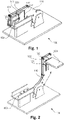
- Fig. 1 and Fig. 2 show views of an interior trim component 100.
- the interior trim component 100 is formed as a table.
- the interior component 100 comprises a support member 110 and a functional member 120.
- Fig. 1 and 2 show two different positions of the interior trim component 100.
- the support member 110 In the position shown in Fig. 1 , the support member 110 is in its retracted position. In this position, the functional member 120 is in its stowage position. In the position shown in Fig. 2 , the support member 110 is in its extended position. In this position, the functional member 120 is in its use position.
- the support member 110 In the retracted position, the support member 110 is stowed in a stowage compartment 150. In the extended position, the interior trim component 100 is unfolded and can be used. As can be seen in Fig. 2 , for example, the functional member 120 is in a horizontal position and can be used as a surface for working at, eating from or on which to place things.
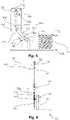
- Figs. 3 to 6 show more detailed views of the interior trim component 100, which can be used to explain the mechanism of the interior trim component 100.
- Fig. 3 and 4 show the support member 110 in the retracted position and Fig. 5 and 6 show the support member 110 in the extended position.
- the interior trim component 100 comprises a motion mechanism 140.
- the motion mechanism 140 is adapted to move the support member 110 from the retracted position to the extended position.
- the motion mechanism 140 comprises an actuator 141 for moving the support member 110.
- the actuator 141 is preferably a gas spring having a cylinder and a sliding piston. One end of the sliding piston is attached to the support member 110, the other end is attached to the cylinder and, for example, the vehicle floor. This allows the actuator 141 to pivot the support member 110 as it extends.
- the motion mechanism 140 further comprises a fixed gear member 142 arranged to be held in a fixed position when the support member 110 is moved and a movable gear member 143 meshing with the fixed gear member 142 and being movable together with the support member 110.
- the fixed gear member 142 is preferably formed as a gear segment and the movable gear member 143 is preferably formed as a gear wheel.
- the actuator 141 is preferably attached to the support member 110 at a position close to the movable gear member 143 in order to achieve a good power transmission.
- the movable gear member 143 comprises a toothed portion 143a which is wider than the toothed portion 142a of the fixed gear member 142.
- the movable gear member 143 comprises a protruding toothed portion which extends beyond the fixed gear member 142.
- the motion mechanism 140 further comprises a flexible drive 144.
- the flexible drive 144 is configured to transmit motion from the movable gear member 143 to a release mechanism 130 of the functional member 120.
- the flexible drive 144 is in direct engagement with the movable gear member 143.
- the flexible drive 144 is connected to the protruding toothed portion of the movable gear member 142.
- the flexible drive 144 is a toothed belt drive.
- the flexible drive 144 transmits motion from a lower portion 112 of the support member 112 to an upper portion 111 in which the release mechanism 130 of the functional member 120 is formed.
- the support member 110 comprises an angled portion 113, where the upper portion 111 and the lower portion 112 of the support member 110 meet at an angle.
- the motion mechanism 140 comprises two guide pulleys 145a, 145b. The guide pulleys 145a, 145b are used to guide the flexible drive 144 through the angled portion 113 of the support member 110.
- a first guide pulley 145a is arranged on a flexible drive portion 144a leading to the release mechanism 130 and a second guide pulley 145b is arranged on a flexible drive portion 144b coming from the release mechanism 130. This ensures a safe transmission of motion between the movable gear member 143 and the release mechanism 130.
- the release mechanism 130 comprises a slide member 131.
- the slide member 131 is connected to the functional member 120 via two levers 132.
- the levers 132 are attached to an end portion of the functional member 120, wherein the functional member 120 is configured to pivot around the levers 132. This allows to unfold the functional member 120.
- a support that interacts with the release mechanism 130 is shown particularly clearly.
- the support comprises a linear motion bearing 121, a supporting element 122 and two further levers 132.
- the linear motion bearing 121 bears the supporting element 122.
- the supporting element 122 is pivotally connected to the two further levers 123 which are connected to the support member 110.
- the motion of the interior trim component 100 can be best described with reference to Fig. 1 and Fig. 2 .
- the flexible drive 144 transmits the rotation of the movable gear member 143 to a linear motion of the slide member 131.
- the slide member 131 is connected to the functional member 120 via the two levers 132 such that the functional member 120 moves linearly relative to the supporting element 122 via the linear motion bearing 121.
- the supporting element 122 hits the end of the linear motion bearing 121, no further linear movement between the functional member 120 and the supporting element 122 is possible.
- the slide member 131 continues to move the end of the functional member 120, this causes the supporting element 122, which is held by the further levers 123, to pull the functional member 120 downwards so that the functional member 120 unfolds.
Landscapes
- Engineering & Computer Science (AREA)
- Mechanical Engineering (AREA)
- Transportation (AREA)
- Vehicle Step Arrangements And Article Storage (AREA)
- Transmission Devices (AREA)
- Vehicle Interior And Exterior Ornaments, Soundproofing, And Insulation (AREA)
Abstract
Description
- The present invention relates to an interior trim component for a vehicle comprising a support member movable between a retracted position and an extended position, a functional member movably attached to the support member between a stowage position and a use position, and a motion mechanism adapted at least to move the support member from the retracted position to the extended position. In particular, the interior trim component is a table in a motor vehicle.
- The present invention is described below mainly in connection with a table in a motor vehicle. However, the idea can be used with respect to various interior trim components such as tables, trays or holders in vehicles.
- The vehicle tables known to date have to be extracted by hand from a non-ergonomic position with significant physical effort. The table must then be positioned in a series of unfolding and rotating steps. There are typically complex mechanisms for executing the related movements. However, such complex mechanisms are expensive and vulnerable. As the above steps are usually carried out from unfavorable positions, they require both skill and strength on the part of the person operating the table.
- In view of the future with the goal of autonomous driving, the interior of a vehicle must be better adapted to the needs of the occupants. It would therefore be desirable to provide a simpler and, in particular, more ergonomic interior trim component.
- Taking the above statements as basis, the object of the present invention is that of providing an interior trim component that is simpler and more convenient to handle, does not obstruct the occupant and which nevertheless has a mechanism which is as simple as possible.
- The object is solved by the subject matter of the independent claim 1. Advantageous developments of the invention are specified in the dependent claims, the description and the accompanying figures.
- According to the invention, an interior trim component for a vehicle is proposed comprising: a support member movable between a retracted position and an extended position, a functional member movably attached to the support member by means of a release mechanism between a stowage position and a use position, and a motion mechanism adapted at least to move the support member from the retracted position to the extended position.
- The support member supports the functional member. In the retracted position, the support member is retracted and preferably stowed in a stowage compartment. For example, the stowage compartment may be the center console. In the extended position, the support member is extended and located outside of the stowage compartment. The path from the retracted position to the extended position is configured in such a way that there is no obstruction by or for a seated person.
- In the stowage position, the functional member is stowed on the support member, for example held in a folded position. In the use position, the functional member is unfolded and ready for use. The use position may be a basic use position of the functional member, from which the functional member can be moved into further use positions. In this way, for example, a usable area of the functional member can be increased. The functional member can be stowed together with the support member in the center console, e.g. under the center armrest.
- According to the invention, the motion mechanism comprises an actuator for moving the support member, a fixed gear member arranged to be held in a fixed position when the support member is moved, a movable gear member meshing with the fixed gear member and being movable together with the support member, and a flexible drive for transmitting motion from the movable gear member to the release mechanism of the functional member.
- The actuator is a mechanism that acts on the support member to move it from the retracted position to the extended position. Preferably, the actuator comprises a release mechanism, for example a button or switch. When the release mechanism is actuated, the actuator is adapted to move the support member to its extended position. Preferably, the actuator comprises a biasing mechanism. In general, the actuator may be a hydraulic, pneumatic, electric or mechanical actuator.
- Preferably, the actuator comprises a spring, most preferably a gas spring. The gas spring uses compressed gas contained within an enclosed cylinder sealed by a sliding piston to pneumatically store potential energy. The gas spring enables a force that is almost independent of the spring displacement and has a small space requirement. It is further easily possible to integrate a damping mechanism into the spring. This makes the movement of the interior trim component steady and smooth.
- Accordingly, the interior trim component pivots out of the stowage compartment automatically with the help of the actuator, e.g. the gas spring, after the release mechanism is actuated. By manually pivoting the support member back into the retracted position, the biasing mechanism, e.g. the gas spring in the system is biased again. The position of the seated person is ergonomically more favorable when pivoting into the retracted position than when pivoting out into the extended position.
- As the fixed gear member is arranged in a fixed position, when the support member is moved, the support member moves relative to the fixed gear member. The support member can, for example, pivot around the fixed gear member. The fixed gear member may be attached to the vehicle floor. The movable gear member is preferably rotatably attached to the support member, in particular a housing thereof.
- The flexible drive transmits motion from the movable gear member to the release mechanism of the functional member. The flexible drive is formed as a traction mechanism comprising traction means adapted to transmit force between the movable gear member and the release mechanism. The traction means can be, for example, a belt or a chain. As an alternative, it is also possible that the traction means are designed as a wire or tape made of metal or plastic. Then there would preferably be an additional support lever.
- The movable gear member moves together with the support member. Accordingly, when moving the support member, the movable gear member rotates. The flexible drive is adapted to transmit the rotation of the movable gear member to the release mechanism. Accordingly, the motion mechanism is configured such that by moving the support member from the retracted position in the extended position, the functional member moves from the stowage position in the use position. Due to this mechanism, it is further only necessary to pivot the support member back into the retracted position, wherein the functional member pivots automatically with it into the stowage position.
- The advantage here is that the interior trim component can be brought in a use position with a single actuation of the actuator. This brings a significant increase in comfort for the vehicle occupants when operating the interior trim component. Further, the motion mechanism is very simply formed with only two gear members.
- According to an advantageous further development of the interior trim component according to the invention, the fixed gear member is formed as a gear segment and the movable gear member is formed as a gear wheel.
- This allows for a particularly simple and less vulnerable configuration of the two gear members.
- Preferably, in the interior trim component according to the invention, the flexible drive is a chain drive or a toothed belt.
- A chain drive or toothed belt does not need large friction surfaces for power transmission like normal belt drives, for example. Therefore, smaller gear diameters are possible. Further, no pretension is necessary, which relieves the bearings.
- In a preferred embodiment of the present invention, the flexible drive is in direct engagement with the movable gear member.
- Direct engagement means an immediate engagement where there is no further transmission element between the movable gear member and the flexible drive. As a result, the motion mechanism has only a low level of complexity.
- Advantageously, the movable gear member comprises a toothed portion which is wider than the toothed portion of the fixed gear member.
- As a result, the movable gear member comprises a protruding toothed portion which extends beyond the fixed gear member. The protruding toothed portion can be used to transmit force directly from the movable gear member to the flexible drive.
- In a preferred embodiment of the present invention, the motion mechanism comprises at least one guide pulley for supporting a change of direction of the flexible drive.
- Preferably, the support member comprises at least one angled or bent portion. At this angled portion, an upper portion and a lower portion of the support member meet. The guide pulley is used to guide the flexible drive through the angled portion of the support member. Preferably, the guide pulley is rotatably attached to the support member. For example, the guide pulley is a wheel on an axle or shaft that is attached to the support member. The guide pulley may be toothed or at least substantially smooth. The guide pulley may have protruding portions, e.g. edges, to accommodate the flexible drive.
- By using at least one guide pulley, it is possible to avoid a second flexible drive for deflecting the motion. Thus, only one flexible drive is necessary. Accordingly, the number of parts is reduced, which leads to a low component complexity.
- According to an advantageous further development of the interior trim component according to the invention, the motion mechanism comprises at least two guide pulleys, wherein a first guide pulley is arranged on a flexible drive portion leading to the release mechanism and a second guide pulley is arranged on a flexible drive portion coming from the release mechanism.
- With two guide pulleys, the mechanism is especially reliable.
- According to an advantageous embodiment, the release mechanism preferably comprises a slide member connected to the flexible drive and being movable together with the flexible drive in a linear direction.
- The slide member enables simple and reliable power transmission from the flexible drive to the functional element.
- In a preferred embodiment of the present invention, the slide member is connected to at least one lever which is connected to the functional member to transmit motion from the slide member to the functional member.
- Preferably, the slide member is connected to two levers to transmit the motion to the functional member. Particularly preferably, the slide member can be arranged on the flexible drive in such a way that one lever is arranged on one side of the flexible drive and the other lever is arranged on the other side of the flexible drive. In other words, the flexible drive runs in between the two levers. This results in a robust design. Further preferably, the support member comprises two slots through each of which one of the levers extends.
- Advantageously, the functional member is pivotally connected to the at least one lever.
- This enables the linear movement of the flexible drive or slide member to be converted into a pivoting movement of the functional member. This makes it possible to open or unfold the functional member. Accordingly, the functional member can be pivoted from the stowage position to the use position.
- According to an advantageous further development of the interior trim component according to the invention, the functional member comprises a linear motion bearing movably bearing a supporting element.
- Preferably, the supporting element is pivotally connected to at least one further lever connected to the support member.
- The slide member is preferably attached to an end portion of the functional member by means of the at least one lever. When the slide member is moved, the functional member moves linearly relative to the supporting element supported by the linear motion bearing. At some point the supporting element will hit the end of the linear motion bearing, so that no further movement in the linear direction is possible. However, the slide member continues to move the end of the functional member, whereupon the supporting element pulls the functional member downwards so that the functional member unfolds. In doing so, the functional member pivots around the at least one lever.
- In a preferred embodiment of the present invention, the supporting element is connected to two further levers, the two further levers being arranged on opposite sides of the functional member and projecting above the functional member, when the functional member is in its stowage position.
- This allows for a particularly compact design, especially when the functional member is in the stowage position.
- Advantageously, the interior trim component according to the invention is a table and the functional member is a plate.
- Further advantages and developments as well as features of the present invention are revealed by the following detailed description of an exemplary embodiment made with reference to the accompanying drawings.
-
Figs. 1 to 6 illustrate an exemplary embodiment of an interior trim component according to the present invention in different views and level of detail. In this regard, - Fig. 1
- shows a view of the interior trim component with the support member in the retracted position;
- Fig. 2
- shows a view of the interior trim component with the support member in the extended position;
- Fig. 3 and 4
- show detailed views of the interior trim component with the support member in the retracted position, with the motion mechanism visible; and
- Fig. 5 and 6
- show detailed views of the interior trim component with the support member in the extended position, with the motion mechanism visible.
- Consequently, in the different views, identical parts are designated by identical reference numerals.
-
Fig. 1 and Fig. 2 show views of aninterior trim component 100. Theinterior trim component 100 is formed as a table. Theinterior component 100 comprises asupport member 110 and afunctional member 120. -
Fig. 1 and 2 show two different positions of theinterior trim component 100. In the position shown inFig. 1 , thesupport member 110 is in its retracted position. In this position, thefunctional member 120 is in its stowage position. In the position shown inFig. 2 , thesupport member 110 is in its extended position. In this position, thefunctional member 120 is in its use position. - In the retracted position, the
support member 110 is stowed in astowage compartment 150. In the extended position, theinterior trim component 100 is unfolded and can be used. As can be seen inFig. 2 , for example, thefunctional member 120 is in a horizontal position and can be used as a surface for working at, eating from or on which to place things. - The other reference numerals shown in
Fig. 1 and 2 will be explained later to describe the motion of theinterior trim component 100. -
Figs. 3 to 6 show more detailed views of theinterior trim component 100, which can be used to explain the mechanism of theinterior trim component 100.Fig. 3 and 4 show thesupport member 110 in the retracted position andFig. 5 and 6 show thesupport member 110 in the extended position. - The
interior trim component 100 comprises amotion mechanism 140. Themotion mechanism 140 is adapted to move thesupport member 110 from the retracted position to the extended position. As shown inFig. 4 , themotion mechanism 140 comprises anactuator 141 for moving thesupport member 110. Theactuator 141 is preferably a gas spring having a cylinder and a sliding piston. One end of the sliding piston is attached to thesupport member 110, the other end is attached to the cylinder and, for example, the vehicle floor. This allows theactuator 141 to pivot thesupport member 110 as it extends. - The
motion mechanism 140 further comprises a fixedgear member 142 arranged to be held in a fixed position when thesupport member 110 is moved and amovable gear member 143 meshing with the fixedgear member 142 and being movable together with thesupport member 110. As can be seen inFig. 3 andFig. 5 , the fixedgear member 142 is preferably formed as a gear segment and themovable gear member 143 is preferably formed as a gear wheel. - The
actuator 141 is preferably attached to thesupport member 110 at a position close to themovable gear member 143 in order to achieve a good power transmission. - As can be seen in
Fig. 4 andFig. 6 , themovable gear member 143 comprises atoothed portion 143a which is wider than thetoothed portion 142a of the fixedgear member 142. In other words, themovable gear member 143 comprises a protruding toothed portion which extends beyond the fixedgear member 142. - The
motion mechanism 140 further comprises aflexible drive 144. Theflexible drive 144 is configured to transmit motion from themovable gear member 143 to arelease mechanism 130 of thefunctional member 120. Theflexible drive 144 is in direct engagement with themovable gear member 143. For example, theflexible drive 144 is connected to the protruding toothed portion of themovable gear member 142. In the shown embodiment, theflexible drive 144 is a toothed belt drive. - The
flexible drive 144 transmits motion from alower portion 112 of thesupport member 112 to anupper portion 111 in which therelease mechanism 130 of thefunctional member 120 is formed. - As can be seen in
Fig. 3 andFig. 5 , thesupport member 110 comprises anangled portion 113, where theupper portion 111 and thelower portion 112 of thesupport member 110 meet at an angle. To support a change of direction of theflexible drive 144 themotion mechanism 140 comprises twoguide pulleys flexible drive 144 through theangled portion 113 of thesupport member 110. - A
first guide pulley 145a is arranged on aflexible drive portion 144a leading to therelease mechanism 130 and asecond guide pulley 145b is arranged on aflexible drive portion 144b coming from therelease mechanism 130. This ensures a safe transmission of motion between themovable gear member 143 and therelease mechanism 130. - As can be seen in the
Figs. 3 ,5 and 6 , therelease mechanism 130 comprises aslide member 131. Theslide member 131 is connected to thefunctional member 120 via twolevers 132. As shown inFig. 6 , thelevers 132 are attached to an end portion of thefunctional member 120, wherein thefunctional member 120 is configured to pivot around thelevers 132. This allows to unfold thefunctional member 120. - In
Fig. 4 andFig. 6 , a support that interacts with therelease mechanism 130 is shown particularly clearly. The support comprises a linear motion bearing 121, a supportingelement 122 and twofurther levers 132. The linear motion bearing 121 bears the supportingelement 122. The supportingelement 122 is pivotally connected to the twofurther levers 123 which are connected to thesupport member 110. - The motion of the
interior trim component 100 can be best described with reference toFig. 1 and Fig. 2 . When pivoting thesupport member 122, theflexible drive 144 transmits the rotation of themovable gear member 143 to a linear motion of theslide member 131. Theslide member 131 is connected to thefunctional member 120 via the twolevers 132 such that thefunctional member 120 moves linearly relative to the supportingelement 122 via thelinear motion bearing 121. When the supportingelement 122 hits the end of the linear motion bearing 121, no further linear movement between thefunctional member 120 and the supportingelement 122 is possible. When theslide member 131 continues to move the end of thefunctional member 120, this causes the supportingelement 122, which is held by thefurther levers 123, to pull thefunctional member 120 downwards so that thefunctional member 120 unfolds. - Although the present invention has been explained in detail with reference to a purely exemplary embodiment, it goes without saying that the present invention is not limited to this embodiment, but rather that modifications and changes are possible within the scope of the following claims.
-
- 100
- interior trim component
- 110
- support member
- 111
- upper portion
- 112
- lower portion
- 113
- angled portion
- 120
- functional member
- 121
- linear motion bearing
- 122
- supporting element
- 123
- further lever
- 130
- release mechanism
- 131
- slide member
- 132
- lever
- 140
- motion mechanism
- 141
- actuator
- 142
- fixed gear member
- 142a
- toothed portion (of the fixed gear member)
- 143
- movable gear member
- 143a
- toothed portion (of the movable gear member)
- 144
- flexible drive
- 144a
- flexible drive portion leading to the release mechanism
- 144b
- flexible drive portion coming from the release mechanism
- 145a
- first guide pulley
- 145b
- second guide pulley
- 150
- stowage compartment
Claims (14)
- An interior trim component (100) for a vehicle comprising:• a support member (110) movable between a retracted position and an extended position,• a functional member (120) movably attached to the support member (110) by means of a release mechanism (130) between a stowage position and a use position, and• a motion mechanism (140) adapted at least to move the support member (110) from the retracted position to the extended position, wherein the motion mechanism (140) comprises:∘ an actuator (141) for moving the support member (110),∘ a fixed gear member (142) arranged to be held in a fixed position when the support member (110) is moved,∘ a movable gear member (143) meshing with the fixed gear member (142) and being movable together with the support member (110), and∘ a flexible drive (144) for transmitting motion from the movable gear member (143) to the release mechanism (130) of the functional member (120).
- The interior trim component (100) of claim 1, wherein the fixed gear member (142) is formed as a gear segment and the movable gear member (143) is formed as a gear wheel.
- The interior trim component (100) of claim 1 or 2, wherein the flexible drive (144) is a chain drive or a toothed belt.
- The interior trim component (100) of any one of the preceding claims, wherein the flexible drive (144) is in direct engagement with the movable gear member (143).
- The interior trim component (100) of claim 4, wherein the movable gear member (143) comprises a toothed portion (143a) which is wider than the toothed portion (142a) of the fixed gear member (142).
- The interior trim component (100) of any one of the preceding claims, wherein the motion mechanism (140) comprises at least one guide pulley (145a, 145b) for supporting a change of direction of the flexible drive (144).
- The interior trim component (100) of claim 6, wherein the motion mechanism (140) comprises at least two guide pulleys (145a, 145b), wherein a first guide pulley (145a) is arranged on a flexible drive portion (144a) leading to the release mechanism (130) and a second guide pulley (145b) is arranged on a flexible drive portion (144b) coming from the release mechanism (130).
- The interior trim component (100) of any one of the preceding claims, wherein the release mechanism (130) comprises a slide member (131) connected to the flexible drive (144) and being movable together with the flexible drive (144) in a linear direction.
- The interior trim component (100) of claim 8, wherein the slide member (131) is connected to at least one lever (132) which is connected to the functional member (120) to transmit motion from the slide member (131) to the functional member (120).
- The interior trim component (100) of claim 9, wherein the functional member (120) is pivotally connected to the at least one lever (132).
- The interior trim component (100) of any one of the preceding claims, wherein the functional member (120) comprises a linear motion bearing (121) movably bearing a supporting element (122).
- The interior trim component (100) of claim 11, wherein the supporting element (122) is pivotally connected to at least one further lever (123) connected to the support member (110).
- The interior trim component (100) of claim 11 or 12, wherein the supporting element (122) is connected to two further levers (123), the two further levers (123) being arranged on opposite sides of the functional member (110) and projecting above the functional member (110), when the functional member (110) is in its stowage position.
- The interior trim component (100) of any one of the preceding claims, wherein the interior trim component (100) is a table and the functional member (110) is a plate.
Applications Claiming Priority (1)
| Application Number | Priority Date | Filing Date | Title |
|---|---|---|---|
| GB2104519.0A GB2605393B (en) | 2021-03-30 | 2021-03-30 | Interior Trim Component |
Publications (3)
| Publication Number | Publication Date |
|---|---|
| EP4067167A1 true EP4067167A1 (en) | 2022-10-05 |
| EP4067167B1 EP4067167B1 (en) | 2024-03-13 |
| EP4067167B8 EP4067167B8 (en) | 2024-04-17 |
Family
ID=75783540
Family Applications (1)
| Application Number | Title | Priority Date | Filing Date |
|---|---|---|---|
| EP22161880.4A Active EP4067167B8 (en) | 2021-03-30 | 2022-03-14 | Interior trim component |
Country Status (2)
| Country | Link |
|---|---|
| EP (1) | EP4067167B8 (en) |
| GB (1) | GB2605393B (en) |
Citations (4)
| Publication number | Priority date | Publication date | Assignee | Title |
|---|---|---|---|---|
| WO2004005069A1 (en) * | 2002-07-08 | 2004-01-15 | Johnson Controls Gmbh | Table assembly, particularly for use in a motor vehicle |
| US8267472B2 (en) * | 2007-05-11 | 2012-09-18 | Thales | Seat provided with a pivoting display screen |
| DE102017209812A1 (en) * | 2017-06-09 | 2018-12-13 | Bayerische Motoren Werke Aktiengesellschaft | Folding table arrangement for a motor vehicle and motor vehicle center console with such a folding table arrangement |
| DE102018100272A1 (en) * | 2018-01-08 | 2019-07-11 | Lisa Dräxlmaier GmbH | Table arrangement for a vehicle and method for actuating the table arrangement |
Family Cites Families (1)
| Publication number | Priority date | Publication date | Assignee | Title |
|---|---|---|---|---|
| KR102264389B1 (en) * | 2019-11-13 | 2021-06-14 | 현대트랜시스 주식회사 | Power table device for vehicle |
-
2021
- 2021-03-30 GB GB2104519.0A patent/GB2605393B/en active Active
-
2022
- 2022-03-14 EP EP22161880.4A patent/EP4067167B8/en active Active
Patent Citations (4)
| Publication number | Priority date | Publication date | Assignee | Title |
|---|---|---|---|---|
| WO2004005069A1 (en) * | 2002-07-08 | 2004-01-15 | Johnson Controls Gmbh | Table assembly, particularly for use in a motor vehicle |
| US8267472B2 (en) * | 2007-05-11 | 2012-09-18 | Thales | Seat provided with a pivoting display screen |
| DE102017209812A1 (en) * | 2017-06-09 | 2018-12-13 | Bayerische Motoren Werke Aktiengesellschaft | Folding table arrangement for a motor vehicle and motor vehicle center console with such a folding table arrangement |
| DE102018100272A1 (en) * | 2018-01-08 | 2019-07-11 | Lisa Dräxlmaier GmbH | Table arrangement for a vehicle and method for actuating the table arrangement |
Also Published As
| Publication number | Publication date |
|---|---|
| GB2605393B (en) | 2023-04-12 |
| EP4067167B8 (en) | 2024-04-17 |
| EP4067167B1 (en) | 2024-03-13 |
| GB202104519D0 (en) | 2021-05-12 |
| GB2605393A (en) | 2022-10-05 |
Similar Documents
| Publication | Publication Date | Title |
|---|---|---|
| US6079763A (en) | Foldable multi-position automotive vehicle seat | |
| US7513565B2 (en) | Power dual action rocker board | |
| US10988966B2 (en) | Furniture drive system | |
| US4462185A (en) | Door operating device for a slide door unit | |
| US11166569B2 (en) | Chair | |
| US6131242A (en) | Damping device | |
| US9789964B2 (en) | Electronically actuated cable release mechanism for adjustable aircraft passenger seat features and method therefor | |
| US20160272098A1 (en) | Deployable Table Apparatus | |
| US20200208719A1 (en) | Device having a main support and an equipment support | |
| CN223546209U (en) | Folding table top device | |
| EP4420935A1 (en) | Vehicle and a foldable display device for use therein | |
| US11412856B2 (en) | Armrest | |
| GB2345437A (en) | Handle arrangement for a moveable part of a motor vehicle | |
| CN109154171A (en) | The external opening control device of motor vehicles | |
| EP4067167A1 (en) | Interior trim component | |
| EP1510732A3 (en) | Neutral start mechanism for a hydrostatic transmission | |
| US6886859B2 (en) | Clamping mechanism for an adjustable steering column | |
| KR102239751B1 (en) | Automobile retractable outside door handle apparatus | |
| EP2065240A2 (en) | Cabriolet with an opening/closing apparatus for the rear shelf | |
| JP2010089682A (en) | Arm rest device | |
| KR100435342B1 (en) | Auxiliary seat for bus | |
| US20060237989A1 (en) | Vehicle decklid system with planetary gear | |
| US7066048B2 (en) | Brake pedal designed to equip a motor vehicle | |
| US20260014917A1 (en) | Electric folding table arrangement for a vehicle interior | |
| CN109969207B (en) | Front end opening and closing mechanism for railway vehicle and railway vehicle with front end opening and closing mechanism |
Legal Events
| Date | Code | Title | Description |
|---|---|---|---|
| PUAI | Public reference made under article 153(3) epc to a published international application that has entered the european phase |
Free format text: ORIGINAL CODE: 0009012 |
|
| STAA | Information on the status of an ep patent application or granted ep patent |
Free format text: STATUS: THE APPLICATION HAS BEEN PUBLISHED |
|
| AK | Designated contracting states |
Kind code of ref document: A1 Designated state(s): AL AT BE BG CH CY CZ DE DK EE ES FI FR GB GR HR HU IE IS IT LI LT LU LV MC MK MT NL NO PL PT RO RS SE SI SK SM TR |
|
| STAA | Information on the status of an ep patent application or granted ep patent |
Free format text: STATUS: REQUEST FOR EXAMINATION WAS MADE |
|
| 17P | Request for examination filed |
Effective date: 20230307 |
|
| RBV | Designated contracting states (corrected) |
Designated state(s): AL AT BE BG CH CY CZ DE DK EE ES FI FR GB GR HR HU IE IS IT LI LT LU LV MC MK MT NL NO PL PT RO RS SE SI SK SM TR |
|
| GRAP | Despatch of communication of intention to grant a patent |
Free format text: ORIGINAL CODE: EPIDOSNIGR1 |
|
| STAA | Information on the status of an ep patent application or granted ep patent |
Free format text: STATUS: GRANT OF PATENT IS INTENDED |
|
| RIC1 | Information provided on ipc code assigned before grant |
Ipc: B60R 11/00 20060101ALI20230929BHEP Ipc: B64D 11/06 20060101ALI20230929BHEP Ipc: B60N 3/00 20060101AFI20230929BHEP |
|
| INTG | Intention to grant announced |
Effective date: 20231027 |
|
| GRAS | Grant fee paid |
Free format text: ORIGINAL CODE: EPIDOSNIGR3 |
|
| GRAA | (expected) grant |
Free format text: ORIGINAL CODE: 0009210 |
|
| STAA | Information on the status of an ep patent application or granted ep patent |
Free format text: STATUS: THE PATENT HAS BEEN GRANTED |
|
| AK | Designated contracting states |
Kind code of ref document: B1 Designated state(s): AL AT BE BG CH CY CZ DE DK EE ES FI FR GB GR HR HU IE IS IT LI LT LU LV MC MK MT NL NO PL PT RO RS SE SI SK SM TR |
|
| REG | Reference to a national code |
Ref country code: GB Ref legal event code: FG4D |
|
| REG | Reference to a national code |
Ref country code: CH Ref legal event code: EP |
|
| RBV | Designated contracting states (corrected) |
Designated state(s): AL AT BE BG CH CY CZ DE DK EE ES FI FR GR HR HU IE IS IT LI LT LU LV MC MK MT NL NO PL PT RO RS SE SI SK SM TR |
|
| RBV | Designated contracting states (corrected) |
Designated state(s): AL AT BE BG CH CY CZ DE DK EE ES FI FR GB GR HR HU IE IS IT LI LT LU LV MC MK MT NL NO PL PT RO RS SE SI SK SM TR |
|
| REG | Reference to a national code |
Ref country code: CH Ref legal event code: PK Free format text: BERICHTIGUNG B8 Ref country code: DE Ref legal event code: R096 Ref document number: 602022002302 Country of ref document: DE |
|
| RBV | Designated contracting states (corrected) |
Designated state(s): AL AT BE BG CH CY CZ DE DK EE ES FI FR GR HR HU IE IS IT LI LT LU LV MC MK MT NL NO PL PT RO RS SE SI SK SM TR |
|
| REG | Reference to a national code |
Ref country code: IE Ref legal event code: FG4D |
|
| PG25 | Lapsed in a contracting state [announced via postgrant information from national office to epo] |
Ref country code: LT Free format text: LAPSE BECAUSE OF FAILURE TO SUBMIT A TRANSLATION OF THE DESCRIPTION OR TO PAY THE FEE WITHIN THE PRESCRIBED TIME-LIMIT Effective date: 20240313 |
|
| REG | Reference to a national code |
Ref country code: LT Ref legal event code: MG9D |
|
| PG25 | Lapsed in a contracting state [announced via postgrant information from national office to epo] |
Ref country code: GR Free format text: LAPSE BECAUSE OF FAILURE TO SUBMIT A TRANSLATION OF THE DESCRIPTION OR TO PAY THE FEE WITHIN THE PRESCRIBED TIME-LIMIT Effective date: 20240614 |
|
| REG | Reference to a national code |
Ref country code: NL Ref legal event code: MP Effective date: 20240313 |
|
| PG25 | Lapsed in a contracting state [announced via postgrant information from national office to epo] |
Ref country code: HR Free format text: LAPSE BECAUSE OF FAILURE TO SUBMIT A TRANSLATION OF THE DESCRIPTION OR TO PAY THE FEE WITHIN THE PRESCRIBED TIME-LIMIT Effective date: 20240313 Ref country code: RS Free format text: LAPSE BECAUSE OF FAILURE TO SUBMIT A TRANSLATION OF THE DESCRIPTION OR TO PAY THE FEE WITHIN THE PRESCRIBED TIME-LIMIT Effective date: 20240613 |
|
| PG25 | Lapsed in a contracting state [announced via postgrant information from national office to epo] |
Ref country code: ES Free format text: LAPSE BECAUSE OF FAILURE TO SUBMIT A TRANSLATION OF THE DESCRIPTION OR TO PAY THE FEE WITHIN THE PRESCRIBED TIME-LIMIT Effective date: 20240313 |
|
| PG25 | Lapsed in a contracting state [announced via postgrant information from national office to epo] |
Ref country code: RS Free format text: LAPSE BECAUSE OF FAILURE TO SUBMIT A TRANSLATION OF THE DESCRIPTION OR TO PAY THE FEE WITHIN THE PRESCRIBED TIME-LIMIT Effective date: 20240613 Ref country code: NO Free format text: LAPSE BECAUSE OF FAILURE TO SUBMIT A TRANSLATION OF THE DESCRIPTION OR TO PAY THE FEE WITHIN THE PRESCRIBED TIME-LIMIT Effective date: 20240613 Ref country code: LT Free format text: LAPSE BECAUSE OF FAILURE TO SUBMIT A TRANSLATION OF THE DESCRIPTION OR TO PAY THE FEE WITHIN THE PRESCRIBED TIME-LIMIT Effective date: 20240313 Ref country code: HR Free format text: LAPSE BECAUSE OF FAILURE TO SUBMIT A TRANSLATION OF THE DESCRIPTION OR TO PAY THE FEE WITHIN THE PRESCRIBED TIME-LIMIT Effective date: 20240313 Ref country code: GR Free format text: LAPSE BECAUSE OF FAILURE TO SUBMIT A TRANSLATION OF THE DESCRIPTION OR TO PAY THE FEE WITHIN THE PRESCRIBED TIME-LIMIT Effective date: 20240614 Ref country code: FI Free format text: LAPSE BECAUSE OF FAILURE TO SUBMIT A TRANSLATION OF THE DESCRIPTION OR TO PAY THE FEE WITHIN THE PRESCRIBED TIME-LIMIT Effective date: 20240313 Ref country code: ES Free format text: LAPSE BECAUSE OF FAILURE TO SUBMIT A TRANSLATION OF THE DESCRIPTION OR TO PAY THE FEE WITHIN THE PRESCRIBED TIME-LIMIT Effective date: 20240313 Ref country code: BG Free format text: LAPSE BECAUSE OF FAILURE TO SUBMIT A TRANSLATION OF THE DESCRIPTION OR TO PAY THE FEE WITHIN THE PRESCRIBED TIME-LIMIT Effective date: 20240313 |
|
| REG | Reference to a national code |
Ref country code: AT Ref legal event code: MK05 Ref document number: 1665458 Country of ref document: AT Kind code of ref document: T Effective date: 20240313 |
|
| PG25 | Lapsed in a contracting state [announced via postgrant information from national office to epo] |
Ref country code: SE Free format text: LAPSE BECAUSE OF FAILURE TO SUBMIT A TRANSLATION OF THE DESCRIPTION OR TO PAY THE FEE WITHIN THE PRESCRIBED TIME-LIMIT Effective date: 20240313 Ref country code: LV Free format text: LAPSE BECAUSE OF FAILURE TO SUBMIT A TRANSLATION OF THE DESCRIPTION OR TO PAY THE FEE WITHIN THE PRESCRIBED TIME-LIMIT Effective date: 20240313 |
|
| PG25 | Lapsed in a contracting state [announced via postgrant information from national office to epo] |
Ref country code: NL Free format text: LAPSE BECAUSE OF FAILURE TO SUBMIT A TRANSLATION OF THE DESCRIPTION OR TO PAY THE FEE WITHIN THE PRESCRIBED TIME-LIMIT Effective date: 20240313 |
|
| PG25 | Lapsed in a contracting state [announced via postgrant information from national office to epo] |
Ref country code: NL Free format text: LAPSE BECAUSE OF FAILURE TO SUBMIT A TRANSLATION OF THE DESCRIPTION OR TO PAY THE FEE WITHIN THE PRESCRIBED TIME-LIMIT Effective date: 20240313 |
|
| PG25 | Lapsed in a contracting state [announced via postgrant information from national office to epo] |
Ref country code: IS Free format text: LAPSE BECAUSE OF FAILURE TO SUBMIT A TRANSLATION OF THE DESCRIPTION OR TO PAY THE FEE WITHIN THE PRESCRIBED TIME-LIMIT Effective date: 20240713 |
|
| PG25 | Lapsed in a contracting state [announced via postgrant information from national office to epo] |
Ref country code: PT Free format text: LAPSE BECAUSE OF FAILURE TO SUBMIT A TRANSLATION OF THE DESCRIPTION OR TO PAY THE FEE WITHIN THE PRESCRIBED TIME-LIMIT Effective date: 20240715 Ref country code: SM Free format text: LAPSE BECAUSE OF FAILURE TO SUBMIT A TRANSLATION OF THE DESCRIPTION OR TO PAY THE FEE WITHIN THE PRESCRIBED TIME-LIMIT Effective date: 20240313 |
|
| PG25 | Lapsed in a contracting state [announced via postgrant information from national office to epo] |
Ref country code: CZ Free format text: LAPSE BECAUSE OF FAILURE TO SUBMIT A TRANSLATION OF THE DESCRIPTION OR TO PAY THE FEE WITHIN THE PRESCRIBED TIME-LIMIT Effective date: 20240313 Ref country code: EE Free format text: LAPSE BECAUSE OF FAILURE TO SUBMIT A TRANSLATION OF THE DESCRIPTION OR TO PAY THE FEE WITHIN THE PRESCRIBED TIME-LIMIT Effective date: 20240313 |
|
| PG25 | Lapsed in a contracting state [announced via postgrant information from national office to epo] |
Ref country code: AT Free format text: LAPSE BECAUSE OF FAILURE TO SUBMIT A TRANSLATION OF THE DESCRIPTION OR TO PAY THE FEE WITHIN THE PRESCRIBED TIME-LIMIT Effective date: 20240313 |
|
| PG25 | Lapsed in a contracting state [announced via postgrant information from national office to epo] |
Ref country code: PL Free format text: LAPSE BECAUSE OF FAILURE TO SUBMIT A TRANSLATION OF THE DESCRIPTION OR TO PAY THE FEE WITHIN THE PRESCRIBED TIME-LIMIT Effective date: 20240313 |
|
| PG25 | Lapsed in a contracting state [announced via postgrant information from national office to epo] |
Ref country code: SK Free format text: LAPSE BECAUSE OF FAILURE TO SUBMIT A TRANSLATION OF THE DESCRIPTION OR TO PAY THE FEE WITHIN THE PRESCRIBED TIME-LIMIT Effective date: 20240313 |
|
| PG25 | Lapsed in a contracting state [announced via postgrant information from national office to epo] |
Ref country code: SM Free format text: LAPSE BECAUSE OF FAILURE TO SUBMIT A TRANSLATION OF THE DESCRIPTION OR TO PAY THE FEE WITHIN THE PRESCRIBED TIME-LIMIT Effective date: 20240313 Ref country code: SK Free format text: LAPSE BECAUSE OF FAILURE TO SUBMIT A TRANSLATION OF THE DESCRIPTION OR TO PAY THE FEE WITHIN THE PRESCRIBED TIME-LIMIT Effective date: 20240313 Ref country code: RO Free format text: LAPSE BECAUSE OF FAILURE TO SUBMIT A TRANSLATION OF THE DESCRIPTION OR TO PAY THE FEE WITHIN THE PRESCRIBED TIME-LIMIT Effective date: 20240313 Ref country code: PT Free format text: LAPSE BECAUSE OF FAILURE TO SUBMIT A TRANSLATION OF THE DESCRIPTION OR TO PAY THE FEE WITHIN THE PRESCRIBED TIME-LIMIT Effective date: 20240715 Ref country code: PL Free format text: LAPSE BECAUSE OF FAILURE TO SUBMIT A TRANSLATION OF THE DESCRIPTION OR TO PAY THE FEE WITHIN THE PRESCRIBED TIME-LIMIT Effective date: 20240313 Ref country code: IS Free format text: LAPSE BECAUSE OF FAILURE TO SUBMIT A TRANSLATION OF THE DESCRIPTION OR TO PAY THE FEE WITHIN THE PRESCRIBED TIME-LIMIT Effective date: 20240713 Ref country code: EE Free format text: LAPSE BECAUSE OF FAILURE TO SUBMIT A TRANSLATION OF THE DESCRIPTION OR TO PAY THE FEE WITHIN THE PRESCRIBED TIME-LIMIT Effective date: 20240313 Ref country code: CZ Free format text: LAPSE BECAUSE OF FAILURE TO SUBMIT A TRANSLATION OF THE DESCRIPTION OR TO PAY THE FEE WITHIN THE PRESCRIBED TIME-LIMIT Effective date: 20240313 Ref country code: AT Free format text: LAPSE BECAUSE OF FAILURE TO SUBMIT A TRANSLATION OF THE DESCRIPTION OR TO PAY THE FEE WITHIN THE PRESCRIBED TIME-LIMIT Effective date: 20240313 |
|
| PG25 | Lapsed in a contracting state [announced via postgrant information from national office to epo] |
Ref country code: LU Free format text: LAPSE BECAUSE OF NON-PAYMENT OF DUE FEES Effective date: 20240314 |
|
| PG25 | Lapsed in a contracting state [announced via postgrant information from national office to epo] |
Ref country code: LU Free format text: LAPSE BECAUSE OF NON-PAYMENT OF DUE FEES Effective date: 20240314 |
|
| PG25 | Lapsed in a contracting state [announced via postgrant information from national office to epo] |
Ref country code: IT Free format text: LAPSE BECAUSE OF FAILURE TO SUBMIT A TRANSLATION OF THE DESCRIPTION OR TO PAY THE FEE WITHIN THE PRESCRIBED TIME-LIMIT Effective date: 20240313 |
|
| REG | Reference to a national code |
Ref country code: DE Ref legal event code: R097 Ref document number: 602022002302 Country of ref document: DE Ref country code: BE Ref legal event code: MM Effective date: 20240331 |
|
| PG25 | Lapsed in a contracting state [announced via postgrant information from national office to epo] |
Ref country code: IT Free format text: LAPSE BECAUSE OF FAILURE TO SUBMIT A TRANSLATION OF THE DESCRIPTION OR TO PAY THE FEE WITHIN THE PRESCRIBED TIME-LIMIT Effective date: 20240313 |
|
| PG25 | Lapsed in a contracting state [announced via postgrant information from national office to epo] |
Ref country code: MC Free format text: LAPSE BECAUSE OF FAILURE TO SUBMIT A TRANSLATION OF THE DESCRIPTION OR TO PAY THE FEE WITHIN THE PRESCRIBED TIME-LIMIT Effective date: 20240313 |
|
| PG25 | Lapsed in a contracting state [announced via postgrant information from national office to epo] |
Ref country code: DK Free format text: LAPSE BECAUSE OF FAILURE TO SUBMIT A TRANSLATION OF THE DESCRIPTION OR TO PAY THE FEE WITHIN THE PRESCRIBED TIME-LIMIT Effective date: 20240313 |
|
| PG25 | Lapsed in a contracting state [announced via postgrant information from national office to epo] |
Ref country code: BE Free format text: LAPSE BECAUSE OF NON-PAYMENT OF DUE FEES Effective date: 20240331 |
|
| PLBE | No opposition filed within time limit |
Free format text: ORIGINAL CODE: 0009261 |
|
| STAA | Information on the status of an ep patent application or granted ep patent |
Free format text: STATUS: NO OPPOSITION FILED WITHIN TIME LIMIT |
|
| PG25 | Lapsed in a contracting state [announced via postgrant information from national office to epo] |
Ref country code: IE Free format text: LAPSE BECAUSE OF NON-PAYMENT OF DUE FEES Effective date: 20240314 |
|
| PG25 | Lapsed in a contracting state [announced via postgrant information from national office to epo] |
Ref country code: MC Free format text: LAPSE BECAUSE OF FAILURE TO SUBMIT A TRANSLATION OF THE DESCRIPTION OR TO PAY THE FEE WITHIN THE PRESCRIBED TIME-LIMIT Effective date: 20240313 Ref country code: IE Free format text: LAPSE BECAUSE OF NON-PAYMENT OF DUE FEES Effective date: 20240314 Ref country code: DK Free format text: LAPSE BECAUSE OF FAILURE TO SUBMIT A TRANSLATION OF THE DESCRIPTION OR TO PAY THE FEE WITHIN THE PRESCRIBED TIME-LIMIT Effective date: 20240313 Ref country code: BE Free format text: LAPSE BECAUSE OF NON-PAYMENT OF DUE FEES Effective date: 20240331 |
|
| 26N | No opposition filed |
Effective date: 20241216 |
|
| PGFP | Annual fee paid to national office [announced via postgrant information from national office to epo] |
Ref country code: DE Payment date: 20250331 Year of fee payment: 4 |
|
| PG25 | Lapsed in a contracting state [announced via postgrant information from national office to epo] |
Ref country code: SI Free format text: LAPSE BECAUSE OF FAILURE TO SUBMIT A TRANSLATION OF THE DESCRIPTION OR TO PAY THE FEE WITHIN THE PRESCRIBED TIME-LIMIT Effective date: 20240313 |
|
| PG25 | Lapsed in a contracting state [announced via postgrant information from national office to epo] |
Ref country code: CY Free format text: LAPSE BECAUSE OF FAILURE TO SUBMIT A TRANSLATION OF THE DESCRIPTION OR TO PAY THE FEE WITHIN THE PRESCRIBED TIME-LIMIT; INVALID AB INITIO Effective date: 20220314 |
|
| REG | Reference to a national code |
Ref country code: CH Ref legal event code: H13 Free format text: ST27 STATUS EVENT CODE: U-0-0-H10-H13 (AS PROVIDED BY THE NATIONAL OFFICE) Effective date: 20251024 |
|
| PG25 | Lapsed in a contracting state [announced via postgrant information from national office to epo] |
Ref country code: TR Free format text: LAPSE BECAUSE OF FAILURE TO SUBMIT A TRANSLATION OF THE DESCRIPTION OR TO PAY THE FEE WITHIN THE PRESCRIBED TIME-LIMIT Effective date: 20240313 |
|
| PGFP | Annual fee paid to national office [announced via postgrant information from national office to epo] |
Ref country code: FR Payment date: 20251231 Year of fee payment: 5 |
|
| PG25 | Lapsed in a contracting state [announced via postgrant information from national office to epo] |
Ref country code: CH Free format text: LAPSE BECAUSE OF NON-PAYMENT OF DUE FEES Effective date: 20250331 |