EP4066758A1 - Tissue-removing catheter with a coupled inner liner - Google Patents
Tissue-removing catheter with a coupled inner liner Download PDFInfo
- Publication number
- EP4066758A1 EP4066758A1 EP22165290.2A EP22165290A EP4066758A1 EP 4066758 A1 EP4066758 A1 EP 4066758A1 EP 22165290 A EP22165290 A EP 22165290A EP 4066758 A1 EP4066758 A1 EP 4066758A1
- Authority
- EP
- European Patent Office
- Prior art keywords
- tissue
- inner liner
- catheter
- liner
- removing element
- Prior art date
- Legal status (The legal status is an assumption and is not a legal conclusion. Google has not performed a legal analysis and makes no representation as to the accuracy of the status listed.)
- Granted
Links
Images





Classifications
-
- A—HUMAN NECESSITIES
- A61—MEDICAL OR VETERINARY SCIENCE; HYGIENE
- A61B—DIAGNOSIS; SURGERY; IDENTIFICATION
- A61B17/00—Surgical instruments, devices or methods
- A61B17/32—Surgical cutting instruments
- A61B17/3205—Excision instruments
- A61B17/3207—Atherectomy devices working by cutting or abrading; Similar devices specially adapted for non-vascular obstructions
- A61B17/320758—Atherectomy devices working by cutting or abrading; Similar devices specially adapted for non-vascular obstructions with a rotating cutting instrument, e.g. motor driven
-
- A—HUMAN NECESSITIES
- A61—MEDICAL OR VETERINARY SCIENCE; HYGIENE
- A61B—DIAGNOSIS; SURGERY; IDENTIFICATION
- A61B17/00—Surgical instruments, devices or methods
- A61B17/00234—Surgical instruments, devices or methods for minimally invasive surgery
- A61B2017/00292—Surgical instruments, devices or methods for minimally invasive surgery mounted on or guided by flexible, e.g. catheter-like, means
- A61B2017/00336—Surgical instruments, devices or methods for minimally invasive surgery mounted on or guided by flexible, e.g. catheter-like, means with a protective sleeve, e.g. retractable or slidable
-
- A—HUMAN NECESSITIES
- A61—MEDICAL OR VETERINARY SCIENCE; HYGIENE
- A61B—DIAGNOSIS; SURGERY; IDENTIFICATION
- A61B17/00—Surgical instruments, devices or methods
- A61B2017/00367—Details of actuation of instruments, e.g. relations between pushing buttons, or the like, and activation of the tool, working tip, or the like
- A61B2017/00398—Details of actuation of instruments, e.g. relations between pushing buttons, or the like, and activation of the tool, working tip, or the like using powered actuators, e.g. stepper motors, solenoids
-
- A—HUMAN NECESSITIES
- A61—MEDICAL OR VETERINARY SCIENCE; HYGIENE
- A61B—DIAGNOSIS; SURGERY; IDENTIFICATION
- A61B17/00—Surgical instruments, devices or methods
- A61B2017/00477—Coupling
-
- A—HUMAN NECESSITIES
- A61—MEDICAL OR VETERINARY SCIENCE; HYGIENE
- A61B—DIAGNOSIS; SURGERY; IDENTIFICATION
- A61B17/00—Surgical instruments, devices or methods
- A61B2017/00831—Material properties
- A61B2017/00876—Material properties magnetic
-
- A—HUMAN NECESSITIES
- A61—MEDICAL OR VETERINARY SCIENCE; HYGIENE
- A61B—DIAGNOSIS; SURGERY; IDENTIFICATION
- A61B17/00—Surgical instruments, devices or methods
- A61B17/22—Implements for squeezing-off ulcers or the like on inner organs of the body; Implements for scraping-out cavities of body organs, e.g. bones; for invasive removal or destruction of calculus using mechanical vibrations; for removing obstructions in blood vessels, not otherwise provided for
- A61B2017/22038—Implements for squeezing-off ulcers or the like on inner organs of the body; Implements for scraping-out cavities of body organs, e.g. bones; for invasive removal or destruction of calculus using mechanical vibrations; for removing obstructions in blood vessels, not otherwise provided for with a guide wire
- A61B2017/22049—Means for locking the guide wire in the catheter
Definitions
- the present disclosure generally relates to a tissue-removing catheter, and more particular, to a coupled inner liner of a tissue-removing catheter.
- Tissue-removing catheters are used to remove unwanted tissue in body lumens.
- atherectomy catheters are used to remove material from a blood vessel to open the blood vessel and improve blood flow through the vessel. This process can be used to prepare lesions within a patient's coronary artery to facilitate percutaneous coronary angioplasty (PTCA) or stent delivery in patients with severely calcified coronary artery lesions.
- PTCA percutaneous coronary angioplasty
- Atherectomy catheters typically employ a rotating element which is used to abrade or otherwise break up the unwanted tissue.
- a tissue-removing catheter for removing tissue in a body lumen generally comprises an elongate body having an axis, and proximal and distal end portions spaced apart from one another along the axis.
- the elongate body is sized and shaped to be received in the body lumen.
- a handle is mounted to the proximal end portion of the elongate body.
- the handle comprises a housing enclosing components operable to cause rotation of the elongate body.
- a tissue-removing element is mounted on the distal end portion of the elongate body. The tissue-removing element is configured to remove the tissue as the tissue-removing element is rotated by the elongate body within the body lumen.
- An inner liner is received within the elongate body and defines a guidewire lumen.
- An advancer is mounted on the handle and is movable relative to the housing.
- the inner liner is coupled to the advancer at a proximal end portion of the inner liner such that movement of the advancer causes a corresponding movement of the inner liner to exert a push force on the tissue-removing element to advance the tissue-removing element and a pull force on the tissue-removing element to retract the tissue-removing element for moving the tissue-removing element relative to the handle.
- a rotational tissue-removing catheter for removing tissue in a body lumen is generally indicated at reference number 10.
- the illustrated catheter 10 is a rotational atherectomy device suitable for removing (e.g., abrading, cutting, excising, ablating, etc.) occlusive tissue (e.g., embolic tissue, plaque tissue, atheroma, thrombolytic tissue, stenotic tissue, hyperplastic tissue, neoplastic tissue, etc.) from a vessel wall (e.g., coronary arterial wall, etc.).
- the catheter 10 may be used to facilitate percutaneous coronary angioplasty (PTCA) or the subsequent delivery of a stent.
- PTCA percutaneous coronary angioplasty
- CTO chronic total occlusion
- Other body lumens such as the ureter, the biliary duct, respiratory passages, the pancreatic duct, the lymphatic duct, and the like.
- Neoplastic cell growth will often occur as a result of a tumor surrounding and intruding into a body lumen. Removal of such material can thus be beneficial to maintain patency of the body lumen.
- the catheter 10 comprises an elongate drive coil 12 (broadly, an elongate body) disposed around an elongate inner liner 14.
- the drive coil 12 and inner liner 14 extend along a longitudinal axis LA of the catheter from a proximal end portion 16 to a distal end portion 18 of the catheter.
- a tissue-removing element 20 is disposed on a distal end of the drive coil 12 and is configured for rotation to remove tissue from a body lumen as will be explained in greater detail below.
- An isolation sheath 22 is disposed around the drive coil 12.
- the drive coil 12 and the inner liner 14 are both configured to translate relative to the isolation sheath 22.
- the catheter 10 further comprises a handle 40 secured at a proximal end of the isolation sheath 22.
- the handle 40 comprises a housing 41 that supports the components of the handle.
- the housing 41 has a generally elongate egg shape and includes a plurality of housing sections secured together to enclose the internal components of the handle 40.
- the housing 41 includes a bottom housing section 41A, a middle housing section 41B secured to the top of the bottom housing section, and a top housing section 41C secured to the top of the middle housing section.
- the bottom housing section 41A is removable from the middle housing section 41B to provide access to the components of the handle 40 in the interior of the housing 41 by a user. It will be understood that the housing 41 can have other shapes and configurations without departing from the scope of the disclosure.
- the housing 41 supports an actuator 42 (e.g., a lever, a button, a dial, a switch, or other device) configured for selectively actuating a motor 43 disposed in the handle to drive rotation of the drive coil 12, and the tissue-removing element 20 mounted at the distal end of the drive coil.
- the motor 43 is configured to rotate the drive coil 12 and tissue-removing element 20 at speeds of greater than about 80,000 RPM. In one embodiment, the motor 43 rotates the drive coil 12 and tissue-removing element 20 between about 10,000 and about 110,000 RPM.
- the motor 43 is coupled to the drive coil 12 by a gear assembly 44 and drive assembly 48 supported within the housing 41.
- the gear assembly 44 comprises a gearbox housing 55 that mounts and at least partially encloses a pair of gears for transferring the rotation of a shaft of the motor 43 to the drive coil 12.
- a power supply may come from a battery (not shown) contained within the handle 40.
- the battery can provide the current source for the guidewire detection circuit.
- the power supply may come from an external source.
- a slide or advancer 45 is positioned on the handle 40 and is operatively coupled to the inner liner 14 for movement of the inner liner relative to the handle to advance and retract the inner liner, drive coil 12, and tissue-removing element 20.
- the housing 41 of the handle 40 may define a slot 186 which limits the movement of the slide 45 relative to the handle.
- the length of the slot 186 determines the amount of relative movement between the inner liner 14 and the handle 40.
- the slot has a length of about 70 mm (2.8 inches).
- the slide 45 is operatively attached to the advancer frame 73 so that movement of the slide causes movement of the advancer frame.
- the advancer frame 73 comprises an arch shaped body configured to slidingly receive the cylindrically shaped motor 43.
- Bearings 149 ( Fig. 5 ) are mounted on the frame 73. The bearings 149 engage the housing 41 so that the bearings can slide along the housing to facilitate movement of the frame 73 in the housing.
- a guidewire port 47 is mounted on a proximal end of the buckle tube 71.
- the guidewire port 47 is overmolded onto the buckle tube 71.
- the guidewire port 47 may be press fit onto the buckle tube 71.
- the guidewire port 47 provides structure in the handle 40 to support the guidewire at the proximal end of the handle.
- the guidewire port 47 defines an axial passage 152 through which the guidewire 26 extends.
- a guidewire lock may be provided in the guidewire port 47 to lock the guidewire 26 in place relative to the handle.
- the guidewire port 47 may also facilitate flushing of the inner liner 14 by passing a cannula through the guidewire port and into the liner key to allow for flushing.
- the guide tube 223 extends from the gearbox housing 55 at a distal end of the guide tube to a coupling sleeve 122 at a proximal end of the guide tube.
- the guide tube 223 is fixedly attached to the gear box housing 55, and the coupling sleeve 122 is fixedly attached to the guide tube 223.
- the coupling sleeve 122 is press fit onto an outer surface of the proximal end of the guide tube 223.
- the coupling sleeve 122 can be attached to the guide tube 223 by any suitable means.
- the coupling sleeve 122 is movably received in the buckle tube 71.
- the engagement between the coupling sleeve 122 and the buckle tube 71 permits the coupling sleeve and guide tube 223 to translate relative to the buckle tube but prevents rotation of the coupling sleeve and guide tube 223 relative to the buckle tube.
- an interior passage in the buckle tube 71 provides sufficient clearance to receive the coupling sleeve 122 for axial movement but does not allow rotational movement of the coupling sleeve in the buckle tube. In one embodiment, axial translation of at least about 70 mm is permitted.
- the liner 14 and liner key 221 may be broadly considered a liner assembly 224.
- the liner key 221 comprises a locking member 225 and an elongate extension member 227 extending distally from a distal end of the locking member.
- a channel 229 extends through the liner key 221.
- the proximal end of the liner 14 is attached to the extension member 227 to secure the liner to the liner key 221.
- the liner key 221 and the liner 14 move together as a single unit.
- the liner 14 is received in a portion of the channel 229 extending through the extension member 227.
- the liner 14 can be retained in the liner key 221 by any suitable means, including without limitation, glue, thermal bond, and mechanical bond.
- the locking member 225 comprises a cuboidal structure comprising four flat surfaces 241.
- the locking member 225 may have other shapes without departing from the scope of the disclosure.
- the locking member 225 has a non-circular or non-rounded exterior shape.
- the liner key 221, guide tube 223, and buckle tube 71 can have other configurations for permitting relative translation and preventing relative rotation.
- any suitable materials may be used for the liner key 221, guide tube 223, and buckle tube 71.
- the liner key 221 can be formed from Peek, Polyoxymethylene (POM), or polycarbonate (PC).
- the coupling sleeve 122 is configured to allow the liner key 221 to enter the coupling sleeve at any entry angle, and centers the guide tube 223 within the buckle tube 71 which in turn centers and aligns the liner 14 within the drive coil 12. Thus, the liner 14 is prevented from being damaged by the drive coil 12 rotating around the liner.
- the coupling sleeve 122 comprises an elongate member having a generally rectangular shape defining four planar side surfaces 174. The corners of the elongate member are truncated defining four angled corner surfaces 176 connecting adjacent side surfaces 174.
- the coupling sleeve 122 includes a proximal portion 178 and a distal portion 180 extending distally from the proximal portion.
- a guide tube section 182 defines the distal portion 180 of the coupling sleeve 122.
- the guide tube section 182 defines a guide tube passage 183 extending through the guide tube section from a distal end of the guide tube section to a proximal end of the guide tube section.
- the guide tube passage 183 receives a proximal end of the guide tube 223 whereby the guide tube is fixedly attached to the coupling sleeve 122.
- the guide tube 223 terminates at a dead stop (not shown) in the guide tube section 182 to limit insertion depth of the guide tube.
- Arms 184 include a first portion projecting axially from a proximal base section 187, and a second portion at a distal end of the first portion projecting radially inward from the first portion. The arms 184 are configured to capture the liner key 221 within the coupling sleeve 122.
- the liner key 221 when the liner key 221 is inserted into the distal opening of the coupling sleeve 122, the liner key engages the arms 184, and in particular the second portion of the arms, causing the arms to deflect outwards to provide clearance for the liner key and thereby permit the key to move past the second portion of the arms.
- the arms Once the liner key 221 is fully inserted into the coupling sleeve 122 such that an entirety of the locking member 225 is disposed proximally of the second portion of the arms 184, the arms move back to their natural state preventing the liner key from being pulled back out of the distal end of the sleeve.
- the size and configuration of the locking member 225 of the liner key 221 and the proximal base section 187 of the coupling sleeve 122 is such that the liner key is held between the arms thereby capturing the key within the sleeve 122. More particularly, a size of the proximal opening 233 in the proximal base section 187 may narrow adjacent the arms 184 such that the locking member 225 cannot pass through the proximal opening preventing the liner key 221 from being inserted out of the proximal end 231 of the coupling sleeve 122.
- the locking member 225 of the liner key 221 is captured in the sleeve 122 with a degree of play allowing for movement of the key in the proximal and distal directions.
- movement of the locking member 225 may be limited in the distal direction by the second portion of the arms 184, and limited in the proximal direction by the proximal base section 187 of the coupling sleeve 122.
- the allowance of the small amount of movement of the liner key 221 in the coupling sleeve 122 provides assembly tolerance for the catheter components.
- First external ribs 196A extend longitudinally along the top and bottom of the coupling sleeve 122, and second external ribs 196B extend longitudinally along the sides of the sleeve.
- Each external rib 196A, 196B extends generally from the proximal end 231 of the coupling sleeve 122.
- the external ribs 196A, 196B have a rounded outer surface.
- the external ribs 196A, 196B provide an effective circular profile for the coupling sleeve 122 having an effective diameter that provides a close tolerance with the inner diameter of the buckle tube 71 to center the sleeve within the buckle tube and thereby center the liner key 221 and liner 14 within the buckle tube.
- a coupling sleeve 222, 222' is attached directly to gearbox housing 155, 155'.
- the coupling sleeves 222, 222' are formed integrally with the gearbox housing 155, 155'.
- the coupling sleeve 222, 222' could be formed separately from the gearbox housing 155, 155' and suitably attached thereto.
- the coupling sleeves 222, 222' may include an adaptor portion for attaching the coupling sleeve to the gearbox housing 155, 155'.
- the coupling sleeves 222, 222' extend directly from the gearbox housing 155, 155', and a guide tube 323, 323' extends proximally from the coupling sleeve.
- the coupling sleeves 222, 222' are also free of external ribs. Rather, an outer dimension of the coupling sleeves 222, 222' is sized for close tolerance inside buckle tube 171, 171'. Additionally, the sleeves 222, 222' may define both proximal and distal stop surfaces to prevent axial movement of a liner key received in the sleeve.
- the coupling assemblies otherwise function substantially the same as the coupling assembly of the previous embodiment.
- liner key 421 includes arms 384 extending laterally on the key and configured for snap fit engagement with coupling sleeve 322.
- the arms 384 flex inward to allow for clearance to insert the key.
- the arms Once the arms are placed in registration with a side opening 385 in the coupling sleeve 322, the arms 384 flex back to their natural state and become retained in the side opening thereby limiting movement of the key 421 relative to the coupling sleeve.
- the coupling assembly otherwise functions substantially the same as the coupling assemblies of the previous embodiments.
- there may be a 4 mm clearance e.g., 2 mm distal and 2 mm proximal
- This clearance allows the liner key 421 to float relative to coupling sleeve 322 once the arms 384 are received in the side opening 385. Configuring the coupling assembly in this manner may allow for the drive coil 12 to compress prior to the inner liner 14 to relieve the axial load on the liner.
- FIG. 18 another alternative embodiment of a coupling assembly is illustrated.
- one or more magnets 435 are mounted on a coupling sleeve 422 and configured to attach to liner key 521 for securing the liner key and liner 314 to the coupling sleeve 422.
- the liner key 521 is formed from a metallic structure so that the liner key is attracted to the magnets 435 on the coupling sleeve 422.
- the coupling assembly otherwise functions substantially the same as the coupling assemblies of the previous embodiments.
- coupling sleeve 522 is formed integrally with guide tube 623.
- the coupling sleeve 522 and guide tube 623 are injection molded together as one unitary structure.
- the components could be formed by other means without departing from the scope of the disclosure.
- coupling sleeve 522 includes arms 584 configured for snap fit engagement with liner key 621.
- the arms 584 flex outward to allow for clearance to insert the key.
- the arms 584 flex back to their natural state and become retained in the recess thereby limiting movement of the key 621 relative to the coupling sleeve.
- the coupling assembly otherwise functions substantially the same as the coupling assemblies of the previous embodiments.
- arms of the coupling sleeve could engage the liner key by friction fit. Still other configurations for locking the liner ley to the coupling sleeve/guide tube are envisioned without departing from the scope of the disclosure.
- the isolation sheath 22 comprises a tubular sleeve configured to isolate and protect a subject's arterial tissue within a body lumen from the rotating drive coil 12.
- the isolation sheath 22 is fixed to the handle 40 at a proximal end of the sheath and does not rotate.
- the isolation sheath 22 provides a partial enclosure for the drive coil 12 and inner liner 14 to move within the sheath.
- the inner diameter of the isolation sheath 22 is sized to provide clearance for the drive coil 12.
- the space between the isolation sheath 22 and the drive coil 12 allows for the drive coil to rotate within the sheath and provides an area for saline perfusion between the sheath and drive coil.
- the outer diameter of the isolation sheath 22 is sized to provide clearance with an inner diameter of a guide catheter (not shown) for delivering the catheter 10 to the desired location in the body lumen.
- the isolation sheath 22 has an inner diameter of about 0.050 inches (1.27 mm), an outer diameter of about 0.055 inches (1.4 mm), and a length of about 1500 mm (59 inches).
- the isolation sheath 22 can have other dimensions without departing from the scope of the disclosure.
- the isolation sheath 22 is made from Polytetrafluorethylene (PTFE).
- the isolation sheath 22 may comprise a multilayer construction.
- the isolation sheath 22 may comprise an inner layer of perfluoroalkox (PFA), a middle braided wire layer, and an outer layer of Pebax.
- the drive coil may comprise a 7 filar (i.e., wire) coil with a lay angle of about 30 degrees.
- the drive coil 12 could be configured from multiple layers without departing from the scope of the disclosure.
- the drive coil 12 may comprise a base coil layer and a jacket (e.g., Tecothane TM ) disposed over the base layer.
- the drive coil comprises a 15 filar coil with a lay angle of about 45 degrees.
- the Tecothane TM jacket may be disposed over the coil.
- the drive coil 12 may comprise a dual coil layer configuration which also includes an additional jacket layer over the two coil layers.
- the drive coil may comprise an inner coil layer comprising a 15 filar coil with a lay angle of about 45 degrees, and an outer coil layer comprising a 19 filar coil with a lay angle of about 10 degrees.
- Drive coils having other configurations are also envisioned.
- the inner liner 14 comprises a multiple layer tubular body configured to isolate the guidewire 26 from the drive coil 12 and tissue-removing element 20.
- the inner liner 14 is extendable through the handle 40 from a position within the handle to a position distal of the handle.
- the inner liner 14 is coupled to the components within the handle 40 but is not fixedly attached to the housing 41 to allow translation of the inner liner relative to the housing.
- the inner liner 14 has an inner diameter that is sized to pass the guidewire 26. The inner liner 14 protects the guidewire from being damaged by the rotation of the drive coil 12 by isolating the guidewire from the rotatable drive coil.
- the inner liner 14 may also extend past the tissue-removing element 20 to protect the guidewire 26 from the rotating tissue-removing element.
- the inner liner 14 is configured to prevent any contact between the guidewire 26 and the rotating components of the catheter 10. Therefore, any metal-to-metal engagement is eliminated by the inner liner 14.
- This isolation of the drive coil 12 and tissue-removing element 20 from the guidewire 26 also ensures that the rotation of the drive coil and tissue-removing element is not transferred or transmitted to the guidewire.
- a standard guidewire 26 can be used with the catheter 10 because the guidewire does not have to be configured to withstand the torsional effects of the rotating components.
- the inner liner 14 stabilizes the tissue-removing element by providing a centering axis for rotation of the tissue-removing element about the inner liner.
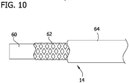
- the inner liner 14 comprises an inner PTFE layer 60 an intermediate braided layer 62 comprised of stainless steel, and an outer layer 64 of polyimide ( Fig. 10 ).
- the PTFE inner layer 60 provides the inner liner 14 with a lubricous interior which aids in the passing of the guidewire 26 though the inner liner.
- the braided stainless steel intermediate layer 62 provides rigidity and strength to the inner liner 14 so that the liner can withstand the torsional forces exerted on the inner liner by the drive coil 12.
- the intermediate layer 62 is formed from 304 stainless steel.
- the outer polyimide layer 64 provides wear resistance as well as having a lubricous quality which reduces friction between the inner liner 14 and the drive coil 12.
- the inner liner 14 has an inner diameter ID of about 0.016 inches (0.4 mm), an outer diameter OD of about 0.019 inches (0.5 mm), and a length of about 59 inches (1500 mm).
- the inner diameter ID of the inner liner 14 provides clearance for the standard 0.014-inch guidewire 26.
- the outer diameter OD of the inner liner 14 provides clearance for the drive coil 12 and tissue-removing element 20. Having a space between the inner liner 14 and the drive coil 12 reduces friction between the two components as well as allows for saline perfusion between the components.
- the tissue-removing element 20 extends along the longitudinal axis LA from a proximal end adjacent the distal end portion of the drive coil 12 to an opposite distal end.
- the tissue-removing element 20 is operatively connected to the motor 43 for being rotated by the motor.
- the tissue-removing element is configured to remove occlusive tissue in the body lumen to separate the tissue from the wall of the body lumen. Any suitable tissue-removing element for removing tissue in the body lumen as it is rotated may be used in one or more embodiments.
- the tissue-removing element 20 comprises an abrasive burr configured to abrade tissue in the body lumen when the motor 43 rotates the abrasive burr.
- the abrasive burr 20 has an abrasive outer surface formed, for example, by a diamond grit coating, surface etching, or the like.
- the tissue-removing element can comprise one or more cutting elements having smooth or serrated cutting edges, a macerator, a thrombectomy wire, etc.
- the diameters of the first, second, third, and fourth diameter portions 74, 78, 82, 86 are constant along their lengths.
- a diameter D1 of the first diameter portion 74 is larger than a diameter D 2 of the second diameter portion 78
- the diameter D2 is larger than a diameter D3 of the third diameter portion 82
- the diameter D3 is larger than a diameter D4 of the fourth diameter portion 86.
- the diameter D1 of the first diameter portion 74 is about 0.037 inches (0.95 mm)
- the diameter D2 of the second diameter portion 78 is about 0.035 inches (0.9 mm)
- the diameter D3 of the third diameter portion 82 is about 0.033 inches (0.85 mm)
- the diameter D4 of the fourth diameter portion 86 is about 0.031 inches (0.8 mm).
- Other cross-sectional dimensions are also envisioned without departing from the scope of the disclosure.
- the inner liner 14 extends through the drive coil 12 and past the distal end of the tissue-removing element 20.
- the fourth diameter portion 86 of the cavity 72 is sized to pass the inner liner 14 with a small clearance.
- the inner diameter D4 provides clearance between the tissue-removing element 20 and the inner liner 14 to reduce friction between the components. Accordingly, the tissue-removing element 20 is shaped and arranged to extend around at least a portion of the drive coil 12 and inner liner 14 and thus provides a relatively compact assembly for abrading tissue at the distal end portion of the catheter 10.
- a bushing 90 is received in the cavity 72 of the tissue-removing element 20 and around the inner liner 14.
- the busing 90 comprises a center ring portion 92, a proximal ring portion 94 extending proximally from the center ring portion, and a distal ring portion 96 extending distally from the center ring portion.
- the ring portions of the bushing 90 define a channel 99 extending through the bushing that receives a portion of the inner liner 14.
- the center ring portion 92 has a larger outer diameter than the proximal and distal ring portions 94, 96.
- the center ring portion 92 is disposed in the second diameter portion 78 of the cavity 72, the proximal ring portion 94 is disposed in the first diameter portion 74, and the distal ring portion 96 is disposed in the second and third diameter portions 78, 82.
- the bushing 90 is made from polyetheretherketone (PEEK) and polytetrafluoroethylene (PTFE).
- PEEK polyetheretherketone
- PTFE polytetrafluoroethylene
- the bushing 90 can be formed from other material without departing from the scope of the disclosure.
- a first bearing 98 is disposed around the proximal ring portion 94 of the bearing 90, and a second bearing 100 is disposed around the distal ring portion 96 of the bearing.
- the first bearing 98 has an outer diameter D5 that is greater than an outer diameter D6 of the second bearing 100.
- the bearings 98, 100 are made from Zirconia.
- the first bearing 98 is disposed in registration with the first diameter portion 74 of the cavity 72 in the tissue-removing element 20 and seats between a distal end of the drive coil 12 at a proximal end of the first bearing, and the center ring portion 92 of the bushing 90 and first shoulder 80 at a distal end of the first bearing.
- the inner liner 14 is not directly attached to the tissue-removing element 20, and the drive coil 12 is not directly attached to the bushing 90, bearings 98, 100, or inner liner.
- rotation of the drive coil 12 and tissue-removing element 20 is not transmitted to the inner liner 14 to also rotate the inner liner. Rather the tissue-removing element 20 rotates around the bushing 90 and bearings 98, 100.
- the inner liner is fixedly attached to the bushing 90, which is retained within the cavity 72 of the tissue-removing element 20 by the drive coil 12, the inner liner 14 is coupled to the drive coil and tissue-removing element through the bushing and bearing arrangement.
- the stiffness of the inner liner 14 is particular suited to efficiently transfer the pushing and pulling force to the tissue-removing element 20 without experiencing the force transfer and friction losses that can occur with using the rotating drive coil 12 to provide the push and pull force. As a result, a direct 1:1 coupling of the advancer 45 to the tissue-removing element 20 is achieved. This also allows a more flexible drive coil 12 to be used since the drive coil is not used to transfer the movement of the advancer 45 to the distal end of the catheter 10.
- a practitioner inserts the guidewire 26 into the body lumen of the subject, to a location distal of the tissue that is to be removed. Subsequently, the practitioner inserts the proximal end portion of the guidewire 26 through the guidewire lumen 24 of the inner liner 14 and through the handle 40 so that the guidewire extends through the proximal port 47 in the handle. With the catheter 10 loaded onto the guidewire 26, the practitioner advances the catheter along the guidewire until the tissue-removing element 20 is positioned proximal and adjacent the tissue.
- the practitioner When the tissue-removing element 20 is positioned proximal and adjacent the tissue, the practitioner actuates the motor 43 using the actuator 42 to rotate the drive coil 12 and the tissue-removing element mounted on the drive coil.
- the tissue-removing element 20 abrades (or otherwise removes) the tissue in the body lumen as it rotates. While the tissue-removing element 20 is rotating, the practitioner may selectively move the drive coil 12 and inner liner 14 distally along the guidewire 26 to abrade the tissue and, for example, increase the size of the passage through the body lumen.
- the practitioner may also move the drive coil 12 and inner liner 14 proximally along the guidewire 26, and may repetitively move the components in distal and proximal directions to obtain a back-and-forth motion of the tissue-removing element 20 across the tissue by sliding the advancer 45 back and forth within the slot 186 in the handle 40.
- the practitioner is able to exercise a greater degree of control over the movement of the tissue-removing element 20 because the coupling between the advancer 45 and the tissue-removing element 20 to transfer the force from the advancer to the tissue-removing element is performed by the relatively stiff inner liner 14. Thus, there is no lost motion between the movement of the advancer 45 and the corresponding movement of the tissue-removing element 20.
- the bushing 90 and bearings 98, 100 couple the inner liner 14 to the tissue-removing element 20 and allow the drive coil 12 and tissue-removing-element to rotate around the inner liner.
- the inner liner 14 also isolates the guidewire 26 from the rotating drive coil 12 and tissue-removing element 20 to protect the guidewire from being damaged by the rotating components.
- the inner liner 14 is configured to withstand the torsional and frictional effects of the rotating drive coil 12 and tissue-removing element 20 without transferring those effects to the guidewire 26.
- the coupling of the inner liner 14 and tissue removing element 20 allows for movement of the inner liner, such as translational movement within the body lumen, to be transmitted to the drive coil 12 and tissue-removing element to move the drive coil and tissue-removing element through the body lumen with the inner liner.
- the catheter can be withdrawn from the body lumen and unloaded from the guidewire 26 by sliding the catheter proximally along the guidewire.
- the guidewire 26 used for the abrading process may remain in the body lumen for use in a subsequent procedure.
Landscapes
- Health & Medical Sciences (AREA)
- Surgery (AREA)
- Life Sciences & Earth Sciences (AREA)
- Biomedical Technology (AREA)
- Nuclear Medicine, Radiotherapy & Molecular Imaging (AREA)
- Engineering & Computer Science (AREA)
- Vascular Medicine (AREA)
- Heart & Thoracic Surgery (AREA)
- Medical Informatics (AREA)
- Molecular Biology (AREA)
- Animal Behavior & Ethology (AREA)
- General Health & Medical Sciences (AREA)
- Public Health (AREA)
- Veterinary Medicine (AREA)
- Surgical Instruments (AREA)
Abstract
Description
- This application claims the benefit of
U.S. Provisional Patent Application Serial No. 63/167,834, filed on March 30, 2021 - The present disclosure generally relates to a tissue-removing catheter, and more particular, to a coupled inner liner of a tissue-removing catheter.
- Tissue-removing catheters are used to remove unwanted tissue in body lumens. As an example, atherectomy catheters are used to remove material from a blood vessel to open the blood vessel and improve blood flow through the vessel. This process can be used to prepare lesions within a patient's coronary artery to facilitate percutaneous coronary angioplasty (PTCA) or stent delivery in patients with severely calcified coronary artery lesions. Atherectomy catheters typically employ a rotating element which is used to abrade or otherwise break up the unwanted tissue.
- In one aspect, a tissue-removing catheter for removing tissue in a body lumen generally comprises an elongate body having an axis, and proximal and distal end portions spaced apart from one another along the axis. The elongate body is sized and shaped to be received in the body lumen. A handle is mounted to the proximal end portion of the elongate body. The handle comprises a housing enclosing components operable to cause rotation of the elongate body. A tissue-removing element is mounted on the distal end portion of the elongate body. The tissue-removing element is configured to remove the tissue as the tissue-removing element is rotated by the elongate body within the body lumen. An inner liner is received within the elongate body and defines a guidewire lumen. An advancer is mounted on the handle and is movable relative to the housing. The inner liner is coupled to the advancer at a proximal end portion of the inner liner such that movement of the advancer causes a corresponding movement of the inner liner to exert a push force on the tissue-removing element to advance the tissue-removing element and a pull force on the tissue-removing element to retract the tissue-removing element for moving the tissue-removing element relative to the handle.
-
-
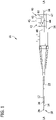
FIG. 1 is a schematic illustration of a catheter of the present disclosure; -
FIG. 2 is an enlarged elevation of a distal end portion of the catheter; -
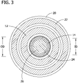
FIG. 3 is a cross section taken through line 3-3 inFig. 2 ; -
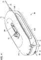
FIG. 4 is a top perspective of a handle of the catheter; -
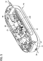
FIG. 5 is a top perspective of the handle with a top housing section removed; -
FIG. 6 is a perspective of gears of a gear assembly in the handle; -
FIG. 7A is an exploded view of internal components in the handle; -
FIG. 7B is a perspective of a coupling sleeve in the handle; -
FIG. 8 is a fragmentary perspective of a liner assembly of the catheter; -
FIG. 9 is a cross section of a liner key of the liner assembly; -
FIG. 10 is a fragmentary elevation of an isolation liner of the catheter with portions broken away to show internal details; -
FIG. 11 is an enlarged fragmentary longitudinal cross section of the distal end portion of the catheter inFig. 2 ; -
FIG. 12 is an enlarged longitudinal cross section of a tissue-removing element of the catheter; -
FIG. 13 is a perspective of a bushing of the catheter; -
FIG. 14 is a perspective of a first bearing of the catheter; -
FIG. 15 is a perspective of a second bearing of the catheter; -
FIG. 16A is an illustration of a coupling assembly of another embodiment; -
FIG. 16B is an illustration of a coupling assembly of another embodiment; -
FIG. 17 is a schematic illustration of a coupling assembly of another embodiment; -
FIG. 18 is an illustration of a coupling assembly of another embodiment; and -
FIGS. 19A-C are illustrations of a coupling assembly of another embodiment. - Corresponding reference characters indicate corresponding parts throughout the drawings.
- Referring to the drawings, and in particular
Fig. 1 , a rotational tissue-removing catheter for removing tissue in a body lumen is generally indicated atreference number 10. The illustratedcatheter 10 is a rotational atherectomy device suitable for removing (e.g., abrading, cutting, excising, ablating, etc.) occlusive tissue (e.g., embolic tissue, plaque tissue, atheroma, thrombolytic tissue, stenotic tissue, hyperplastic tissue, neoplastic tissue, etc.) from a vessel wall (e.g., coronary arterial wall, etc.). Thecatheter 10 may be used to facilitate percutaneous coronary angioplasty (PTCA) or the subsequent delivery of a stent. Features of the disclosed embodiments may also be suitable for treating chronic total occlusion (CTO) of blood vessels, and stenoses of other body lumens and other hyperplastic and neoplastic conditions in other body lumens, such as the ureter, the biliary duct, respiratory passages, the pancreatic duct, the lymphatic duct, and the like. Neoplastic cell growth will often occur as a result of a tumor surrounding and intruding into a body lumen. Removal of such material can thus be beneficial to maintain patency of the body lumen. - The
catheter 10 is sized for being received in a blood vessel of a subject. Thus, thecatheter 10 may have a maximum size of 3, 4, 5, 6, 7, 8, 9, 10, or 12 French (1, 1.3, 1.7, 2, 2.3, 2.7, 3, 3.3, or 4 mm) and may have a working length of 20, 30, 40, 60, 80, 100, 120, 150, 180 or 210 cm depending of the body lumen. While the remaining discussion is directed toward a catheter for removing tissue in blood vessels, it will be appreciated that the teachings of the present disclosure also apply to other types of tissue-removing catheters, including, but not limited to, catheters for penetrating and/or removing tissue from a variety of occlusive, stenotic, or hyperplastic material in a variety of body lumens. - Referring to
Figs. 1-3 , thecatheter 10 comprises an elongate drive coil 12 (broadly, an elongate body) disposed around an elongateinner liner 14. Thedrive coil 12 andinner liner 14 extend along a longitudinal axis LA of the catheter from aproximal end portion 16 to adistal end portion 18 of the catheter. A tissue-removingelement 20 is disposed on a distal end of thedrive coil 12 and is configured for rotation to remove tissue from a body lumen as will be explained in greater detail below. Anisolation sheath 22 is disposed around thedrive coil 12. Thedrive coil 12 and theinner liner 14 are both configured to translate relative to theisolation sheath 22. Thecatheter 10 is sized and shaped for insertion into a body lumen of a subject. Theisolation sheath 22 isolates the body lumen from at least a portion of thedrive coil 12 andinner liner 14. Theinner liner 14 defines a guidewire lumen 24 (Fig. 3 ) for slidably receiving aguidewire 26 therein so that thecatheter 10 can be advanced through the body lumen by traveling along the guidewire. The guidewire can be a standard 0.014-inch outer diameter, 300 cm length guidewire. In certain embodiments, theinner liner 14 may have a lubricious inner surface for sliding over the guidewire 26 (e.g., a lubricious surface may be provided by a lubricious polymer layer or a lubricious coating). In the illustrated embodiment, theguidewire lumen 24 extends along an entire working length of thecatheter 10. In one embodiment, the overall working length of thecatheter 10 may be between about 135 cm (53 inches) and about 142 cm (56 inches). In use, theguidewire 26 may extend about 40 mm (1.6 inches) past a distal end of theinner liner 14. - Referring to
Figs. 1 and4-7 , thecatheter 10 further comprises ahandle 40 secured at a proximal end of theisolation sheath 22. Thehandle 40 comprises ahousing 41 that supports the components of the handle. Thehousing 41 has a generally elongate egg shape and includes a plurality of housing sections secured together to enclose the internal components of thehandle 40. In the illustrated embodiment, thehousing 41 includes abottom housing section 41A, amiddle housing section 41B secured to the top of the bottom housing section, and atop housing section 41C secured to the top of the middle housing section. In one embodiment, thebottom housing section 41A is removable from themiddle housing section 41B to provide access to the components of thehandle 40 in the interior of thehousing 41 by a user. It will be understood that thehousing 41 can have other shapes and configurations without departing from the scope of the disclosure. - The
housing 41 supports an actuator 42 (e.g., a lever, a button, a dial, a switch, or other device) configured for selectively actuating amotor 43 disposed in the handle to drive rotation of thedrive coil 12, and the tissue-removingelement 20 mounted at the distal end of the drive coil. Themotor 43 is configured to rotate thedrive coil 12 and tissue-removingelement 20 at speeds of greater than about 80,000 RPM. In one embodiment, themotor 43 rotates thedrive coil 12 and tissue-removingelement 20 between about 10,000 and about 110,000 RPM. Themotor 43 is coupled to thedrive coil 12 by agear assembly 44 and driveassembly 48 supported within thehousing 41. Thegear assembly 44 comprises agearbox housing 55 that mounts and at least partially encloses a pair of gears for transferring the rotation of a shaft of themotor 43 to thedrive coil 12. - The
motor 43 is coupled to thedrive coil 12 by agear assembly 44 and driveassembly 48 supported within thehousing 41. Thegear assembly 44 comprises agearbox housing 55 that mounts and at least partially encloses a pair of gears for transferring the rotation of a shaft of themotor 43 to thedrive coil 12. Thegearbox housing 55 includes arear housing section 61 and afront housing section 63 formed integrally with the rear housing section such that the gearbox housing comprises a single housing structure (Fig. 7 ). Therear housing section 61 incudes atube sleeve portion 69 on the proximal side of the rear housing section that receives a distal end portion of aguide tube 223. Therear housing section 61 also attaches to a carriage oradvancer frame 73 for moving themotor 43 andgear assembly 44 within thehousing 41. Further, attaching thegearbox housing 55 to the distal end of theadvancer frame 73 secures themotor 43 in the advancer frame so that the motor moves along with the advancer frame. Thefront housing section 63 has a distal sleeve portion that receives a portion ofdrive assembly 48. Adriver gear 81 is attached to themotor 43 such that the driver gear rotates with the motor shaft when themotor 43 is activated (Fig. 6 ). A drivengear 83 is in mesh with thedriver gear 81 so that rotation of the driver gear causes the driven gear to rotate in the opposite direction. Thedrive assembly 48 attaches the drivengear 83 to thedrive coil 12 so that the rotation of the driven gear causes the drive coil to rotate. Acontroller 50 may be provided in thehandle 40. Thecontroller 50 may be programmed to control operation of the catheter. - It is understood that other suitable actuators, including but not limited to touchscreen actuators, wireless control actuators, automated actuators directed by a controller, etc., may be suitable to selectively actuate the motor in other embodiments. In some embodiments, a power supply may come from a battery (not shown) contained within the
handle 40. The battery can provide the current source for the guidewire detection circuit. In other embodiments, the power supply may come from an external source. - Referring to
Figs. 1 ,4 , and5 , a slide oradvancer 45 is positioned on thehandle 40 and is operatively coupled to theinner liner 14 for movement of the inner liner relative to the handle to advance and retract the inner liner,drive coil 12, and tissue-removingelement 20. Thehousing 41 of thehandle 40 may define aslot 186 which limits the movement of theslide 45 relative to the handle. Thus, the length of theslot 186 determines the amount of relative movement between theinner liner 14 and thehandle 40. In one embodiment, the slot has a length of about 70 mm (2.8 inches). Theslide 45 is operatively attached to theadvancer frame 73 so that movement of the slide causes movement of the advancer frame. Theadvancer frame 73 comprises an arch shaped body configured to slidingly receive the cylindrically shapedmotor 43. Bearings 149 (Fig. 5 ) are mounted on theframe 73. Thebearings 149 engage thehousing 41 so that the bearings can slide along the housing to facilitate movement of theframe 73 in the housing. - Referring to
Fig. 7A , aguidewire port 47 is mounted on a proximal end of thebuckle tube 71. In one embodiment, theguidewire port 47 is overmolded onto thebuckle tube 71. Alternatively, theguidewire port 47 may be press fit onto thebuckle tube 71. Theguidewire port 47 provides structure in thehandle 40 to support the guidewire at the proximal end of the handle. Theguidewire port 47 defines anaxial passage 152 through which theguidewire 26 extends. Additionally, a guidewire lock may be provided in theguidewire port 47 to lock theguidewire 26 in place relative to the handle. Theguidewire port 47 may also facilitate flushing of theinner liner 14 by passing a cannula through the guidewire port and into the liner key to allow for flushing. - The
guide tube 223 extends from thegearbox housing 55 at a distal end of the guide tube to acoupling sleeve 122 at a proximal end of the guide tube. Theguide tube 223 is fixedly attached to thegear box housing 55, and thecoupling sleeve 122 is fixedly attached to theguide tube 223. In one embodiment, thecoupling sleeve 122 is press fit onto an outer surface of the proximal end of theguide tube 223. However, thecoupling sleeve 122 can be attached to theguide tube 223 by any suitable means. Thecoupling sleeve 122 is movably received in thebuckle tube 71. The engagement between thecoupling sleeve 122 and thebuckle tube 71 permits the coupling sleeve and guidetube 223 to translate relative to the buckle tube but prevents rotation of the coupling sleeve and guidetube 223 relative to the buckle tube. In particular, an interior passage in thebuckle tube 71 provides sufficient clearance to receive thecoupling sleeve 122 for axial movement but does not allow rotational movement of the coupling sleeve in the buckle tube. In one embodiment, axial translation of at least about 70 mm is permitted. - Referring to
Figs. 7A-9 , aliner key 221 is attached to a proximal end of theliner 14 and is received in thecoupling sleeve 122 securing the liner key to the coupling sleeve. Theliner key 221 may be secured to the coupling sleeve by any suitable means, including without limitation, rotational locking, snap fit, friction fit or a press/glue/thermal bond. Thus, movement of thecoupling sleeve 122 in thebuckle tube 71 causes a corresponding movement of theliner key 221. Theliner key 221 can also facilitate flushing of theinner liner 14. Theliner 14 extends distally from theliner key 221 through theguide tube 223. Theliner 14 andliner key 221 may be broadly considered aliner assembly 224. In the illustrated embodiment, theliner key 221 comprises a lockingmember 225 and anelongate extension member 227 extending distally from a distal end of the locking member. Achannel 229 extends through theliner key 221. The proximal end of theliner 14 is attached to theextension member 227 to secure the liner to theliner key 221. Thus, theliner key 221 and theliner 14 move together as a single unit. In one embodiment, theliner 14 is received in a portion of thechannel 229 extending through theextension member 227. Theliner 14 can be retained in theliner key 221 by any suitable means, including without limitation, glue, thermal bond, and mechanical bond. In the illustrated embodiment, the lockingmember 225 comprises a cuboidal structure comprising fourflat surfaces 241. However, the lockingmember 225 may have other shapes without departing from the scope of the disclosure. In one embodiment, the lockingmember 225 has a non-circular or non-rounded exterior shape. It is envisioned that theliner key 221,guide tube 223, and buckletube 71 can have other configurations for permitting relative translation and preventing relative rotation. Further, any suitable materials may be used for theliner key 221,guide tube 223, and buckletube 71. For example, theliner key 221, can be formed from Peek, Polyoxymethylene (POM), or polycarbonate (PC). - To assembly the
liner assembly 224 in thecatheter 10, the liner assembly is inserted into a distal end 232 of thecoupling sleeve 122 to secure the liner assembly to the coupling sleeve. In particular, theliner 14 is first inserted into a distal opening (not shown) in thecoupling sleeve 122 and pulled through aproximal opening 233 of the coupling sleeve until theliner key 221 is located adjacent the proximal opening. As will be explained in greater detail below, thecoupling sleeve 122 receives theliner key 221 within the coupling sleeve by snap-fit engagement to restrict movement of the liner key relative to the coupling sleeve. Further, thecoupling sleeve 122 is configured to allow theliner key 221 to enter the coupling sleeve at any entry angle, and centers theguide tube 223 within thebuckle tube 71 which in turn centers and aligns theliner 14 within thedrive coil 12. Thus, theliner 14 is prevented from being damaged by thedrive coil 12 rotating around the liner. - In the illustrated embodiment, the
coupling sleeve 122 comprises an elongate member having a generally rectangular shape defining four planar side surfaces 174. The corners of the elongate member are truncated defining four angled corner surfaces 176 connecting adjacent side surfaces 174. Thecoupling sleeve 122 includes aproximal portion 178 and adistal portion 180 extending distally from the proximal portion. In the illustrated embodiment, aguide tube section 182 defines thedistal portion 180 of thecoupling sleeve 122. Theguide tube section 182 defines aguide tube passage 183 extending through the guide tube section from a distal end of the guide tube section to a proximal end of the guide tube section. Theguide tube passage 183 receives a proximal end of theguide tube 223 whereby the guide tube is fixedly attached to thecoupling sleeve 122. In one embodiment, theguide tube 223 terminates at a dead stop (not shown) in theguide tube section 182 to limit insertion depth of the guide tube.Arms 184 include a first portion projecting axially from aproximal base section 187, and a second portion at a distal end of the first portion projecting radially inward from the first portion. Thearms 184 are configured to capture theliner key 221 within thecoupling sleeve 122. For instance, when theliner key 221 is inserted into the distal opening of thecoupling sleeve 122, the liner key engages thearms 184, and in particular the second portion of the arms, causing the arms to deflect outwards to provide clearance for the liner key and thereby permit the key to move past the second portion of the arms. Once theliner key 221 is fully inserted into thecoupling sleeve 122 such that an entirety of the lockingmember 225 is disposed proximally of the second portion of thearms 184, the arms move back to their natural state preventing the liner key from being pulled back out of the distal end of the sleeve. The size and configuration of the lockingmember 225 of theliner key 221 and theproximal base section 187 of thecoupling sleeve 122 is such that the liner key is held between the arms thereby capturing the key within thesleeve 122. More particularly, a size of theproximal opening 233 in theproximal base section 187 may narrow adjacent thearms 184 such that the lockingmember 225 cannot pass through the proximal opening preventing the liner key 221 from being inserted out of theproximal end 231 of thecoupling sleeve 122. In one embodiment, the lockingmember 225 of theliner key 221 is captured in thesleeve 122 with a degree of play allowing for movement of the key in the proximal and distal directions. As such, movement of the lockingmember 225 may be limited in the distal direction by the second portion of thearms 184, and limited in the proximal direction by theproximal base section 187 of thecoupling sleeve 122. The allowance of the small amount of movement of theliner key 221 in thecoupling sleeve 122 provides assembly tolerance for the catheter components. - First
external ribs 196A extend longitudinally along the top and bottom of thecoupling sleeve 122, and secondexternal ribs 196B extend longitudinally along the sides of the sleeve. Eachexternal rib proximal end 231 of thecoupling sleeve 122. In the illustrated embodiment, theexternal ribs external ribs coupling sleeve 122 having an effective diameter that provides a close tolerance with the inner diameter of thebuckle tube 71 to center the sleeve within the buckle tube and thereby center theliner key 221 andliner 14 within the buckle tube. Thus, theliner 14 will be centered within thedrive coil 12 preventing the liner from being damaged by the drive coil rotating around the liner. It will be understood that thecoupling sleeve 122 could have over shapes without departing from the scope of the disclosure. For example, broadly, the coupling sleeve may have a non-circular or non-rounded exterior shape. Further, thecoupling sleeve 122,guide tube 223,gearbox housing 55, andadvancer frame 73 may be broadly considered a coupling assembly for coupling theliner assembly 224, including theinner liner 14, to theadvancer 45. - Referring to
Figs. 16A and 16B , alternative embodiments of coupling assemblies are illustrated. In this embodiment, acoupling sleeve 222, 222' is attached directly togearbox housing 155, 155'. In the illustrated embodiments, thecoupling sleeves 222, 222' are formed integrally with thegearbox housing 155, 155'. However, thecoupling sleeve 222, 222' could be formed separately from thegearbox housing 155, 155' and suitably attached thereto. For example, thecoupling sleeves 222, 222' may include an adaptor portion for attaching the coupling sleeve to thegearbox housing 155, 155'. Thus, thecoupling sleeves 222, 222' extend directly from thegearbox housing 155, 155', and aguide tube 323, 323' extends proximally from the coupling sleeve. Thecoupling sleeves 222, 222' are also free of external ribs. Rather, an outer dimension of thecoupling sleeves 222, 222' is sized for close tolerance insidebuckle tube 171, 171'. Additionally, thesleeves 222, 222' may define both proximal and distal stop surfaces to prevent axial movement of a liner key received in the sleeve. The coupling assemblies otherwise function substantially the same as the coupling assembly of the previous embodiment. - Referring to
Fig. 17 , another alternative embodiment of a coupling assembly is illustrated. In this embodiment,liner key 421 includesarms 384 extending laterally on the key and configured for snap fit engagement with coupling sleeve 322. Thus, when theliner key 421 is inserted into the coupling sleeve 322, thearms 384 flex inward to allow for clearance to insert the key. Once the arms are placed in registration with aside opening 385 in the coupling sleeve 322, thearms 384 flex back to their natural state and become retained in the side opening thereby limiting movement of the key 421 relative to the coupling sleeve. The coupling assembly otherwise functions substantially the same as the coupling assemblies of the previous embodiments. - In the illustrated embodiment, there is a clearance between the
arms 384 and the proximal and distal edges of theside opening 385. For example, there may be a 4 mm clearance (e.g., 2 mm distal and 2 mm proximal) between thearms 384 and the edges of theside opening 385. In one embodiment, there may be up to a 14 mm clearance between thearms 384 and the edges of theside opening 385. This clearance allows theliner key 421 to float relative to coupling sleeve 322 once thearms 384 are received in theside opening 385. Configuring the coupling assembly in this manner may allow for thedrive coil 12 to compress prior to theinner liner 14 to relieve the axial load on the liner. This will help to alleviate an instance where compression of theinner liner 14 causes the liner to bow outward and come into contact with the other components of thecatheter 10 causing wear on the inner liner. Thus, by reducing the compression of theinner liner 14 wear of the inner liner can be reduced. - Referring to
Fig. 18 , another alternative embodiment of a coupling assembly is illustrated. In this embodiment, one ormore magnets 435 are mounted on acoupling sleeve 422 and configured to attach toliner key 521 for securing the liner key andliner 314 to thecoupling sleeve 422. In one embodiment, theliner key 521 is formed from a metallic structure so that the liner key is attracted to themagnets 435 on thecoupling sleeve 422. The coupling assembly otherwise functions substantially the same as the coupling assemblies of the previous embodiments. - Referring to
Figs. 19A-C , another alternative embodiment of a coupling assembly is illustrated. In this embodiment,coupling sleeve 522 is formed integrally withguide tube 623. In one embodiment, thecoupling sleeve 522 and guidetube 623 are injection molded together as one unitary structure. However, the components could be formed by other means without departing from the scope of the disclosure. Additionally,coupling sleeve 522 includesarms 584 configured for snap fit engagement withliner key 621. Thus, when theliner key 621 is inserted into thecoupling sleeve 522, thearms 584 flex outward to allow for clearance to insert the key. Once thearms 584 are placed in registration with arecess 585 in thecoupling sleeve 522, thearms 584 flex back to their natural state and become retained in the recess thereby limiting movement of the key 621 relative to the coupling sleeve. The coupling assembly otherwise functions substantially the same as the coupling assemblies of the previous embodiments. - Additionally or alternatively, arms of the coupling sleeve could engage the liner key by friction fit. Still other configurations for locking the liner ley to the coupling sleeve/guide tube are envisioned without departing from the scope of the disclosure.
- Referring to
Figs. 1 , and3 , theisolation sheath 22 comprises a tubular sleeve configured to isolate and protect a subject's arterial tissue within a body lumen from therotating drive coil 12. Theisolation sheath 22 is fixed to thehandle 40 at a proximal end of the sheath and does not rotate. Theisolation sheath 22 provides a partial enclosure for thedrive coil 12 andinner liner 14 to move within the sheath. The inner diameter of theisolation sheath 22 is sized to provide clearance for thedrive coil 12. The space between theisolation sheath 22 and thedrive coil 12 allows for the drive coil to rotate within the sheath and provides an area for saline perfusion between the sheath and drive coil. The outer diameter of theisolation sheath 22 is sized to provide clearance with an inner diameter of a guide catheter (not shown) for delivering thecatheter 10 to the desired location in the body lumen. In one embodiment, theisolation sheath 22 has an inner diameter of about 0.050 inches (1.27 mm), an outer diameter of about 0.055 inches (1.4 mm), and a length of about 1500 mm (59 inches). Theisolation sheath 22 can have other dimensions without departing from the scope of the disclosure. In one embodiment, theisolation sheath 22 is made from Polytetrafluorethylene (PTFE). Alternatively, theisolation sheath 22 may comprise a multilayer construction. For example, theisolation sheath 22 may comprise an inner layer of perfluoroalkox (PFA), a middle braided wire layer, and an outer layer of Pebax. - Referring to
Figs. 1-3 , thedrive coil 12 may comprise a tubular stainless steel coil configured to transfer rotation and torque from themotor 43 to the tissue-removingelement 20. Configuring thedrive coil 12 as a coiled structure allows for the rotation and torque of thedrive coil 12 to be applied to the tissue-removingelement 20 when thecatheter 10 is traversed across a curved path. The coil configuration of thedrive coil 12 is also configured to expand its inner diameter when the coil is rotated so that the drive coil remains spaced from theinner liner 14 during operation of thecatheter 10. In one embodiment, thedrive coil 12 has an inner diameter of about 0.023 inches (0.6 mm) and an outer diameter of about 0.035 inches (0.9 mm). Thedrive coil 12 may have a single layer construction. For example, the drive coil may comprise a 7 filar (i.e., wire) coil with a lay angle of about 30 degrees. Alternatively, thedrive coil 12 could be configured from multiple layers without departing from the scope of the disclosure. For example, thedrive coil 12 may comprise a base coil layer and a jacket (e.g., Tecothane™) disposed over the base layer. In one embodiment, the drive coil comprises a 15 filar coil with a lay angle of about 45 degrees. The Tecothane™ jacket may be disposed over the coil. Alternatively, thedrive coil 12 may comprise a dual coil layer configuration which also includes an additional jacket layer over the two coil layers. For example, the drive coil may comprise an inner coil layer comprising a 15 filar coil with a lay angle of about 45 degrees, and an outer coil layer comprising a 19 filar coil with a lay angle of about 10 degrees. Drive coils having other configurations are also envisioned. - Referring to
Figs. 1-3 and10 , theinner liner 14 comprises a multiple layer tubular body configured to isolate the guidewire 26 from thedrive coil 12 and tissue-removingelement 20. Theinner liner 14 is extendable through thehandle 40 from a position within the handle to a position distal of the handle. In one embodiment, theinner liner 14 is coupled to the components within thehandle 40 but is not fixedly attached to thehousing 41 to allow translation of the inner liner relative to the housing. Theinner liner 14 has an inner diameter that is sized to pass theguidewire 26. Theinner liner 14 protects the guidewire from being damaged by the rotation of thedrive coil 12 by isolating the guidewire from the rotatable drive coil. Theinner liner 14 may also extend past the tissue-removingelement 20 to protect theguidewire 26 from the rotating tissue-removing element. Thus, theinner liner 14 is configured to prevent any contact between theguidewire 26 and the rotating components of thecatheter 10. Therefore, any metal-to-metal engagement is eliminated by theinner liner 14. This isolation of thedrive coil 12 and tissue-removingelement 20 from theguidewire 26 also ensures that the rotation of the drive coil and tissue-removing element is not transferred or transmitted to the guidewire. As a result, astandard guidewire 26 can be used with thecatheter 10 because the guidewire does not have to be configured to withstand the torsional effects of the rotating components. Additionally, by extending theinner liner 14 through the tissue-removingelement 20 and past the distal end of the tissue-removing element, the inner liner stabilizes the tissue-removing element by providing a centering axis for rotation of the tissue-removing element about the inner liner. - In the illustrated embodiment, the
inner liner 14 comprises aninner PTFE layer 60 anintermediate braided layer 62 comprised of stainless steel, and anouter layer 64 of polyimide (Fig. 10 ). The PTFEinner layer 60 provides theinner liner 14 with a lubricous interior which aids in the passing of theguidewire 26 though the inner liner. The braided stainless steelintermediate layer 62 provides rigidity and strength to theinner liner 14 so that the liner can withstand the torsional forces exerted on the inner liner by thedrive coil 12. In one embodiment, theintermediate layer 62 is formed from 304 stainless steel. Theouter polyimide layer 64 provides wear resistance as well as having a lubricous quality which reduces friction between theinner liner 14 and thedrive coil 12. Additionally, a lubricious film, such as silicone, can be added to theinner liner 14 to reduce friction between the inner liner and thedrive coil 12. In one embodiment, theinner liner 14 has an inner diameter ID of about 0.016 inches (0.4 mm), an outer diameter OD of about 0.019 inches (0.5 mm), and a length of about 59 inches (1500 mm). The inner diameter ID of theinner liner 14 provides clearance for the standard 0.014-inch guidewire 26. The outer diameter OD of theinner liner 14 provides clearance for thedrive coil 12 and tissue-removingelement 20. Having a space between theinner liner 14 and thedrive coil 12 reduces friction between the two components as well as allows for saline perfusion between the components. - Referring to
Figs. 1 ,2 , and11 , the tissue-removingelement 20 extends along the longitudinal axis LA from a proximal end adjacent the distal end portion of thedrive coil 12 to an opposite distal end. The tissue-removingelement 20 is operatively connected to themotor 43 for being rotated by the motor. When thecatheter 10 is inserted into the body lumen and themotor 43 is rotating the tissue-removingelement 20, the tissue-removing element is configured to remove occlusive tissue in the body lumen to separate the tissue from the wall of the body lumen. Any suitable tissue-removing element for removing tissue in the body lumen as it is rotated may be used in one or more embodiments. In the illustrated embodiment, the tissue-removingelement 20 comprises an abrasive burr configured to abrade tissue in the body lumen when themotor 43 rotates the abrasive burr. Theabrasive burr 20 has an abrasive outer surface formed, for example, by a diamond grit coating, surface etching, or the like. In other embodiments, the tissue-removing element can comprise one or more cutting elements having smooth or serrated cutting edges, a macerator, a thrombectomy wire, etc. - Referring to
Fig. 12 , acavity 72 extends longitudinally through the tissue-removingelement 20 such that the tissue-removing element defines openings at its proximal and distal ends. Thecavity 72 includes afirst diameter portion 74 extending distally from the proximal end of the tissue-removingelement 20 and asecond diameter portion 78 extending distally from the first diameter portion forming afirst shoulder 80 disposed between the first and second diameter portions. Athird diameter portion 82 extends distally from thesecond diameter portion 78 and forms asecond shoulder 84 between the second and third diameter portions. Afourth diameter portion 86 extends distally from the third diameter portion to the distal end of the tissue-removing element and forms a third shoulder 88 between the third and fourth diameter portions. The diameters of the first, second, third, andfourth diameter portions first diameter portion 74 is larger than a diameter D2 of thesecond diameter portion 78, the diameter D2 is larger than a diameter D3 of thethird diameter portion 82, and the diameter D3 is larger than a diameter D4 of thefourth diameter portion 86. In one embodiment, the diameter D1 of thefirst diameter portion 74 is about 0.037 inches (0.95 mm), the diameter D2 of thesecond diameter portion 78 is about 0.035 inches (0.9 mm), the diameter D3 of thethird diameter portion 82 is about 0.033 inches (0.85 mm), and the diameter D4 of thefourth diameter portion 86 is about 0.031 inches (0.8 mm). Other cross-sectional dimensions are also envisioned without departing from the scope of the disclosure. - The
inner liner 14 extends through thedrive coil 12 and past the distal end of the tissue-removingelement 20. Thefourth diameter portion 86 of thecavity 72 is sized to pass theinner liner 14 with a small clearance. The inner diameter D4 provides clearance between the tissue-removingelement 20 and theinner liner 14 to reduce friction between the components. Accordingly, the tissue-removingelement 20 is shaped and arranged to extend around at least a portion of thedrive coil 12 andinner liner 14 and thus provides a relatively compact assembly for abrading tissue at the distal end portion of thecatheter 10. - Referring to
Figs. 11-13 , abushing 90 is received in thecavity 72 of the tissue-removingelement 20 and around theinner liner 14. Thebusing 90 comprises acenter ring portion 92, aproximal ring portion 94 extending proximally from the center ring portion, and adistal ring portion 96 extending distally from the center ring portion. The ring portions of thebushing 90 define achannel 99 extending through the bushing that receives a portion of theinner liner 14. In the illustrated embodiment, thecenter ring portion 92 has a larger outer diameter than the proximal anddistal ring portions center ring portion 92 is disposed in thesecond diameter portion 78 of thecavity 72, theproximal ring portion 94 is disposed in thefirst diameter portion 74, and thedistal ring portion 96 is disposed in the second andthird diameter portions bushing 90 is made from polyetheretherketone (PEEK) and polytetrafluoroethylene (PTFE). However, thebushing 90 can be formed from other material without departing from the scope of the disclosure. - Referring to
Figs. 11 ,14, and 15 , afirst bearing 98 is disposed around theproximal ring portion 94 of thebearing 90, and asecond bearing 100 is disposed around thedistal ring portion 96 of the bearing. Thefirst bearing 98 has an outer diameter D5 that is greater than an outer diameter D6 of thesecond bearing 100. In one embodiment, thebearings first bearing 98 is disposed in registration with thefirst diameter portion 74 of thecavity 72 in the tissue-removingelement 20 and seats between a distal end of thedrive coil 12 at a proximal end of the first bearing, and thecenter ring portion 92 of thebushing 90 andfirst shoulder 80 at a distal end of the first bearing. Thesecond bearing 100 is disposed in registration with thesecond diameter portion 78 of thecavity 72 and is seated between thesecond shoulder 84 at a distal end of the second bearing, and thecenter ring portion 92 of thebushing 90 at a proximal end of the second bearing. As such thebushing 90 andbearings cavity 72 of the tissue-removingelement 20. Broadly, thebushing 90 andbearings coupling assembly 57 for coupling theinner liner 14 to the tissue-removingelement 20. - Referring to
Fig. 11 , an interior surface of thebushing 90 is fixedly attached to theinner liner 14 such that the inner liner is coupled to the tissue-removingelement 20 through the bushing. In one embodiment an adhesive such as an epoxy glue bonds thebushing 90 to theinner liner 14. As such, thebushing 90 does not rotate around theinner liner 14. Thedrive coil 12 is directly and fixedly attached to the tissue-removingelement 20. The tissue-removingelement 20 can be fixedly attached to the distal end of thedrive coil 12 by any suitable means. In one embodiment, adhesive bonds thedrive coil 12 to the tissue-removingelement 20. Thedrive coil 12 is received in thefirst diameter portion 74 of thecavity 72 and a distal end of the drive coil abuts thefirst bearing 98. However, theinner liner 14 is not directly attached to the tissue-removingelement 20, and thedrive coil 12 is not directly attached to thebushing 90,bearings drive coil 12 and tissue-removingelement 20 is not transmitted to theinner liner 14 to also rotate the inner liner. Rather the tissue-removingelement 20 rotates around thebushing 90 andbearings bushing 90, which is retained within thecavity 72 of the tissue-removingelement 20 by thedrive coil 12, theinner liner 14 is coupled to the drive coil and tissue-removing element through the bushing and bearing arrangement. - Further, and with reference to
Figs. 5 and7A , fixedly attaching theguide tube 223 to thegearbox housing 55 and attaching the gearbox housing to the distal end of theadvancer frame 73 couples theliner assembly 224 to the advancer frame so that the liner assembly moves along with the advancer frame. Therefore, theinner liner 14, not thedrive coil 12 provides the primary push and pull force to the tissue-removingelement 20 when the advancer 45 is moved relative to thehandle 40. Accordingly, movement of the advancer 45 causes direct translational movement of theinner liner 14 which is then transmitted to thedrive coil 12 and tissue-removingelement 20. This configuration utilizes the structure of theinner liner 14 to transfer the push and pull force to the distal end of thecatheter 10. The stiffness of theinner liner 14 is particular suited to efficiently transfer the pushing and pulling force to the tissue-removingelement 20 without experiencing the force transfer and friction losses that can occur with using therotating drive coil 12 to provide the push and pull force. As a result, a direct 1:1 coupling of the advancer 45 to the tissue-removingelement 20 is achieved. This also allows a moreflexible drive coil 12 to be used since the drive coil is not used to transfer the movement of the advancer 45 to the distal end of thecatheter 10. - Referring to
FIGS. 1 and2 , to remove tissue in the body lumen of a subject, a practitioner inserts theguidewire 26 into the body lumen of the subject, to a location distal of the tissue that is to be removed. Subsequently, the practitioner inserts the proximal end portion of theguidewire 26 through theguidewire lumen 24 of theinner liner 14 and through thehandle 40 so that the guidewire extends through theproximal port 47 in the handle. With thecatheter 10 loaded onto theguidewire 26, the practitioner advances the catheter along the guidewire until the tissue-removingelement 20 is positioned proximal and adjacent the tissue. When the tissue-removingelement 20 is positioned proximal and adjacent the tissue, the practitioner actuates themotor 43 using theactuator 42 to rotate thedrive coil 12 and the tissue-removing element mounted on the drive coil. The tissue-removingelement 20 abrades (or otherwise removes) the tissue in the body lumen as it rotates. While the tissue-removingelement 20 is rotating, the practitioner may selectively move thedrive coil 12 andinner liner 14 distally along theguidewire 26 to abrade the tissue and, for example, increase the size of the passage through the body lumen. The practitioner may also move thedrive coil 12 andinner liner 14 proximally along theguidewire 26, and may repetitively move the components in distal and proximal directions to obtain a back-and-forth motion of the tissue-removingelement 20 across the tissue by sliding the advancer 45 back and forth within theslot 186 in thehandle 40. The practitioner is able to exercise a greater degree of control over the movement of the tissue-removingelement 20 because the coupling between the advancer 45 and the tissue-removingelement 20 to transfer the force from the advancer to the tissue-removing element is performed by the relatively stiffinner liner 14. Thus, there is no lost motion between the movement of the advancer 45 and the corresponding movement of the tissue-removingelement 20. During the abrading process, thebushing 90 andbearings inner liner 14 to the tissue-removingelement 20 and allow thedrive coil 12 and tissue-removing-element to rotate around the inner liner. Theinner liner 14 also isolates the guidewire 26 from therotating drive coil 12 and tissue-removingelement 20 to protect the guidewire from being damaged by the rotating components. As such, theinner liner 14 is configured to withstand the torsional and frictional effects of therotating drive coil 12 and tissue-removingelement 20 without transferring those effects to theguidewire 26. Also, the coupling of theinner liner 14 andtissue removing element 20 allows for movement of the inner liner, such as translational movement within the body lumen, to be transmitted to thedrive coil 12 and tissue-removing element to move the drive coil and tissue-removing element through the body lumen with the inner liner. When the practitioner is finished using thecatheter 10, the catheter can be withdrawn from the body lumen and unloaded from theguidewire 26 by sliding the catheter proximally along the guidewire. Theguidewire 26 used for the abrading process may remain in the body lumen for use in a subsequent procedure. - When introducing elements of the present invention or the one or more embodiment(s) thereof, the articles "a", "an", "the" and "said" are intended to mean that there are one or more of the elements. The terms "comprising", "including" and "having" are intended to be inclusive and mean that there may be additional elements other than the listed elements.
- As various changes could be made in the above apparatuses, systems, and methods without departing from the scope of the invention, it is intended that all matter contained in the above description and shown in the accompanying drawings shall be interpreted as illustrative and not in a limiting sense.
- The following examples are useful to understand the invention:
- 1. A tissue-removing catheter for removing tissue in a body lumen, the tissue-removing catheter comprising:
- an elongate body having an axis, and proximal and distal end portions spaced apart from one another along the axis, wherein the elongate body is sized and shaped to be received in the body lumen;
- a handle mounted to the proximal end portion of the elongate body, the handle comprising a housing enclosing components operable to cause rotation of the elongate body;
- a tissue-removing element mounted on the distal end portion of the elongate body, the tissue-removing element being configured to remove the tissue as the tissue-removing element is rotated by the elongate body within the body lumen;
- an inner liner received within the elongate body and defining a guidewire lumen; and
- an advancer mounted on the handle and movable relative to the housing, the inner liner being coupled to the advancer at a proximal end portion of the inner liner such that movement of the advancer causes a corresponding movement of the inner liner to exert a push force on the tissue-removing element to advance the tissue-removing element and a pull force on the tissue-removing element to retract the tissue-removing element for moving the tissue-removing element relative to the handle.
- 2. The tissue-removing catheter of example 1, further comprising a coupling assembly in the handle coupling the inner liner to the advancer.
- 3. The tissue-removing catheter of any of the preceding examples, wherein the inner liner is coupled to the tissue-removing element at a distal end portion of the inner liner
- 4. The tissue-removing catheter of any of the preceding examples, further comprising a liner assembly including the inner liner and a key fixedly attached to a proximal end of the inner liner, wherein the coupling assembly is directly attached to the key.
- 5. The tissue-removing catheter of example 4, wherein the coupling assembly comprises a coupling sleeve fixedly attached to the key.
- 6. The tissue-removing catheter of example 5, wherein the coupling assembly comprises a guide tube attached to a distal end portion of the coupling sleeve.
- 7. The tissue-removing catheter of any of the preceding examples, further comprising a motor in the handle and operatively engaging the elongate body for driving rotation of the elongate body and tissue-removing element mounted on the elongate body.
- 8. The tissue-removing catheter of example 7, further comprising a gearbox housing at least partially enclosing a gear assembly operatively connected to the motor.
- 9. The tissue-removing catheter of example 8, wherein a proximal end of the guide tube is attached to the coupling sleeve and a distal end of the guide tube is attached to the gearbox housing.
- 10. The tissue-removing catheter of example 9, wherein the guide tube is fixedly attached to the gearbox housing.
- 11. The tissue-removing catheter of example 9 or 10, further comprising a carriage mounting the motor in the handle and connecting the advancer to the gearbox housing.
- 12. The tissue-removing catheter of example 11, wherein the coupling assembly includes the carriage and gearbox housing.
- 13. The tissue-removing catheter of any of the examples 5 to 12, further comprising a buckle tube in the handle, wherein the coupling sleeve is received in the buckle tube in a non-rotational, sliding engagement.
- 14. The tissue-removing catheter of example 13, further comprising a guidewire port mounted on a proximal end of the buckle tube.
- 15. The tissue-removing catheter of any of the examples 5 to 14, wherein the coupling sleeve includes at least one magnet configured to attach to the key.
- 16. The tissue-removing catheter of any of the examples 5 to 14, wherein the coupling sleeve attaches to the key by a snap-fit connection.
- 17. The tissue-removing catheter of example 16, wherein one of the coupling sleeve and key includes deflectable arms configured for snap-fit engagement with the other of the coupling sleeve and key.
- 18. The tissue-removing catheter of any of the examples 2 to 17, wherein the coupling assembly fixedly couples the inner liner to the advancer such that movement of the advancer causes an identical corresponding movement of the inner liner.
- 19. The tissue-removing catheter of example 18, wherein the inner liner is fixedly coupled to the elongate body at the distal end portion of the elongate body.
- 20. The tissue-removing catheter of any of the preceding examples, wherein the inner liner is free of direct attachment to a tissue-removing element.
Claims (15)
- A tissue-removing catheter for removing tissue in a body lumen, the tissue-removing catheter comprising:an elongate body having an axis, and proximal and distal end portions spaced apart from one another along the axis, wherein the elongate body is sized and shaped to be received in the body lumen;a handle mounted to the proximal end portion of the elongate body, the handle comprising a housing enclosing components operable to cause rotation of the elongate body;a tissue-removing element mounted on the distal end portion of the elongate body, the tissue-removing element being configured to remove the tissue as the tissue-removing element is rotated by the elongate body within the body lumen;an inner liner received within the elongate body and defining a guidewire lumen; andan advancer mounted on the handle and movable relative to the housing, the inner liner being coupled to the advancer at a proximal end portion of the inner liner such that movement of the advancer causes a corresponding movement of the inner liner to exert a push force on the tissue-removing element to advance the tissue-removing element and a pull force on the tissue-removing element to retract the tissue-removing element for moving the tissue-removing element relative to the handle.
- The tissue-removing catheter of claim 1, further comprising a coupling assembly in the handle coupling the inner liner to the advancer.
- The tissue-removing catheter of any of the preceding claims, wherein the inner liner is coupled to the tissue-removing element at a distal end portion of the inner liner
- The tissue-removing catheter of any of the preceding claims, further comprising a liner assembly including the inner liner and a key fixedly attached to a proximal end of the inner liner, wherein the coupling assembly is directly attached to the key.
- The tissue-removing catheter as set forth in claim 4, wherein the coupling assembly comprises a coupling sleeve fixedly attached to the key, specifically, wherein the coupling assembly comprises a guide tube attached to a distal end portion of the coupling sleeve.
- The tissue-removing catheter of claim 5, further comprising a motor in the handle and operatively engaging the elongate body for driving rotation of the elongate body and tissue-removing element mounted on the elongate body.
- The tissue-removing catheter as set forth in claim 6, further comprising a gearbox housing at least partially enclosing a gear assembly operatively connected to the motor specifically, wherein a proximal end of the guide tube is attached to the coupling sleeve and a distal end of the guide tube is attached to the gearbox housing.
- The tissue-removing catheter of claim 7, wherein the guide tube is fixedly attached to the gearbox housing.
- The tissue-removing catheter as set forth in claim 7, further comprising a carriage mounting the motor in the handle and connecting the advancer to the gearbox housing, specifically, wherein the coupling assembly includes the carriage and gearbox housing.
- The tissue-removing catheter of any of the claims 5 to 9, further comprising a buckle tube in the handle, wherein the coupling sleeve is received in the buckle tube in a non-rotational, sliding engagement, specifically, wherein the tissue removing catheter further comprises a guidewire port mounted on a proximal end of the buckle tube.
- The tissue-removing catheter of any of the claims 5 to 10, wherein the coupling sleeve includes at least one magnet configured to attach to the key.
- The tissue-removing catheter of any of the claims 5 to 10, wherein the coupling sleeve attaches to the key by a snap-fit connection, specifically, wherein one of the coupling sleeve and key includes deflectable arms configured for snap-fit engagement with the other of the coupling sleeve and key.
- The tissue-removing catheter of any of the claims 2 to 12, wherein the coupling assembly fixedly couples the inner liner to the advancer such that movement of the advancer causes an identical corresponding movement of the inner liner.
- The tissue-removing catheter of claim 13, wherein the inner liner is fixedly coupled to the elongate body at the distal end portion of the elongate body.
- The tissue-removing catheter of any of the preceding claims, wherein the inner liner is free of direct attachment to a tissue-removing element.
Applications Claiming Priority (2)
| Application Number | Priority Date | Filing Date | Title |
|---|---|---|---|
| US202163167834P | 2021-03-30 | 2021-03-30 | |
| US17/654,230 US12239341B2 (en) | 2021-03-30 | 2022-03-09 | Tissue-removing catheter with a coupled inner liner |
Publications (2)
| Publication Number | Publication Date |
|---|---|
| EP4066758A1 true EP4066758A1 (en) | 2022-10-05 |
| EP4066758B1 EP4066758B1 (en) | 2025-09-17 |
Family
ID=80999100
Family Applications (1)
| Application Number | Title | Priority Date | Filing Date |
|---|---|---|---|
| EP22165290.2A Active EP4066758B1 (en) | 2021-03-30 | 2022-03-30 | Tissue-removing catheter with a coupled inner liner |
Country Status (2)
| Country | Link |
|---|---|
| US (2) | US12239341B2 (en) |
| EP (1) | EP4066758B1 (en) |
Citations (2)
| Publication number | Priority date | Publication date | Assignee | Title |
|---|---|---|---|---|
| US20120239066A1 (en) * | 2010-05-13 | 2012-09-20 | Marc-Alan Levine | Rotational thrombectomy wire coupler |
| US20200360047A1 (en) * | 2019-05-17 | 2020-11-19 | Medtronic Vascular, Inc. | Tissue-Removing Catheter |
Family Cites Families (14)
| Publication number | Priority date | Publication date | Assignee | Title |
|---|---|---|---|---|
| US8784421B2 (en) | 2004-03-03 | 2014-07-22 | Boston Scientific Scimed, Inc. | Apparatus and methods for removing vertebral bone and disc tissue |
| US20090204021A1 (en) | 2004-12-16 | 2009-08-13 | Senorx, Inc. | Apparatus and method for accessing a body site |
| US9814519B2 (en) | 2006-04-20 | 2017-11-14 | Boston Scientific Scimed, Inc. | Ablation probe with ribbed insulated sheath |
| US10307340B2 (en) | 2007-11-21 | 2019-06-04 | Actuated Medical, Inc. | Devices for clearing blockages in artificial and natural lumens |
| US8236008B2 (en) * | 2008-02-29 | 2012-08-07 | Envy Medical, Inc. | Microdermabrasion treatment heads |
| CN103200886B (en) | 2010-10-28 | 2015-07-29 | 科维蒂恩有限合伙公司 | Matter removing device and using method |
| EP3102127B1 (en) | 2014-02-06 | 2019-10-09 | Avinger, Inc. | Atherectomy catheter |
| US10307175B2 (en) | 2016-03-26 | 2019-06-04 | Rex Medical, L.P | Atherectomy device |
| CN110582242B (en) | 2017-05-03 | 2023-03-10 | 美敦力瓦斯科尔勒公司 | Tissue removal catheter |
| US10492823B2 (en) | 2017-08-08 | 2019-12-03 | Medtronic Vascular, Inc. | Tissue-removing catheter and method of removing tissue |
| US11160556B2 (en) | 2018-04-23 | 2021-11-02 | Covidien Lp | Threaded trocar for adapter assemblies |
| CN112996447B (en) * | 2018-11-16 | 2024-07-23 | 美敦力瓦斯科尔勒公司 | Tissue Removal Catheter |
| CN210044084U (en) | 2019-03-28 | 2020-02-11 | 徐瑞雪 | A curette for breast surgery |
| ES2987037T3 (en) | 2019-09-11 | 2024-11-13 | Neuravi Ltd | Expandable buccal catheter |
-
2022
- 2022-03-09 US US17/654,230 patent/US12239341B2/en active Active
- 2022-03-30 EP EP22165290.2A patent/EP4066758B1/en active Active
-
2025
- 2025-01-17 US US19/030,591 patent/US20250339172A1/en active Pending
Patent Citations (2)
| Publication number | Priority date | Publication date | Assignee | Title |
|---|---|---|---|---|
| US20120239066A1 (en) * | 2010-05-13 | 2012-09-20 | Marc-Alan Levine | Rotational thrombectomy wire coupler |
| US20200360047A1 (en) * | 2019-05-17 | 2020-11-19 | Medtronic Vascular, Inc. | Tissue-Removing Catheter |
Also Published As
| Publication number | Publication date |
|---|---|
| US12239341B2 (en) | 2025-03-04 |
| EP4066758B1 (en) | 2025-09-17 |
| US20220313307A1 (en) | 2022-10-06 |
| US20250339172A1 (en) | 2025-11-06 |
Similar Documents
| Publication | Publication Date | Title |
|---|---|---|
| US11871958B2 (en) | Tissue-removing catheter with guidewire isolation liner | |
| EP3968877B1 (en) | Tissue-removing catheter | |
| US20250213268A1 (en) | Tissue-removing catheter with inner liner key | |
| EP4066758B1 (en) | Tissue-removing catheter with a coupled inner liner | |
| US12201318B2 (en) | Tissue-removing catheter with a coupled inner liner | |
| CN113616287B (en) | Tissue removal catheter with coupled liner | |
| EP4091559B1 (en) | Tissue-removing catheter with guidewire isolation liner | |
| EP4312830B1 (en) | Tissue-removing catheter with coupled inner liner | |
| EP4140422B1 (en) | Tissue-removing catheter including drive assembly | |
| CN116981414A (en) | Tissue removal catheter with inner lining key |
Legal Events
| Date | Code | Title | Description |
|---|---|---|---|
| PUAI | Public reference made under article 153(3) epc to a published international application that has entered the european phase |
Free format text: ORIGINAL CODE: 0009012 |
|
| STAA | Information on the status of an ep patent application or granted ep patent |
Free format text: STATUS: REQUEST FOR EXAMINATION WAS MADE |
|
| 17P | Request for examination filed |
Effective date: 20220330 |
|
| AK | Designated contracting states |
Kind code of ref document: A1 Designated state(s): AL AT BE BG CH CY CZ DE DK EE ES FI FR GB GR HR HU IE IS IT LI LT LU LV MC MK MT NL NO PL PT RO RS SE SI SK SM TR |
|
| STAA | Information on the status of an ep patent application or granted ep patent |
Free format text: STATUS: EXAMINATION IS IN PROGRESS |
|
| 17Q | First examination report despatched |
Effective date: 20240126 |
|
| GRAP | Despatch of communication of intention to grant a patent |
Free format text: ORIGINAL CODE: EPIDOSNIGR1 |
|
| STAA | Information on the status of an ep patent application or granted ep patent |
Free format text: STATUS: GRANT OF PATENT IS INTENDED |
|
| INTG | Intention to grant announced |
Effective date: 20250408 |
|
| GRAS | Grant fee paid |
Free format text: ORIGINAL CODE: EPIDOSNIGR3 |
|
| GRAA | (expected) grant |
Free format text: ORIGINAL CODE: 0009210 |
|
| STAA | Information on the status of an ep patent application or granted ep patent |
Free format text: STATUS: THE PATENT HAS BEEN GRANTED |
|
| AK | Designated contracting states |
Kind code of ref document: B1 Designated state(s): AL AT BE BG CH CY CZ DE DK EE ES FI FR GB GR HR HU IE IS IT LI LT LU LV MC MK MT NL NO PL PT RO RS SE SI SK SM TR |
|
| REG | Reference to a national code |
Ref country code: GB Ref legal event code: FG4D |
|
| REG | Reference to a national code |
Ref country code: CH Ref legal event code: EP |
|
| REG | Reference to a national code |
Ref country code: DE Ref legal event code: R096 Ref document number: 602022021441 Country of ref document: DE |
|
| REG | Reference to a national code |
Ref country code: IE Ref legal event code: FG4D |
|
| PG25 | Lapsed in a contracting state [announced via postgrant information from national office to epo] |
Ref country code: NO Free format text: LAPSE BECAUSE OF FAILURE TO SUBMIT A TRANSLATION OF THE DESCRIPTION OR TO PAY THE FEE WITHIN THE PRESCRIBED TIME-LIMIT Effective date: 20251217 |
|
| REG | Reference to a national code |
Ref country code: LT Ref legal event code: MG9D |
|
| PG25 | Lapsed in a contracting state [announced via postgrant information from national office to epo] |
Ref country code: FI Free format text: LAPSE BECAUSE OF FAILURE TO SUBMIT A TRANSLATION OF THE DESCRIPTION OR TO PAY THE FEE WITHIN THE PRESCRIBED TIME-LIMIT Effective date: 20250917 |
|
| PG25 | Lapsed in a contracting state [announced via postgrant information from national office to epo] |
Ref country code: HR Free format text: LAPSE BECAUSE OF FAILURE TO SUBMIT A TRANSLATION OF THE DESCRIPTION OR TO PAY THE FEE WITHIN THE PRESCRIBED TIME-LIMIT Effective date: 20250917 |
|
| PG25 | Lapsed in a contracting state [announced via postgrant information from national office to epo] |
Ref country code: GR Free format text: LAPSE BECAUSE OF FAILURE TO SUBMIT A TRANSLATION OF THE DESCRIPTION OR TO PAY THE FEE WITHIN THE PRESCRIBED TIME-LIMIT Effective date: 20251218 |
|
| PG25 | Lapsed in a contracting state [announced via postgrant information from national office to epo] |
Ref country code: SE Free format text: LAPSE BECAUSE OF FAILURE TO SUBMIT A TRANSLATION OF THE DESCRIPTION OR TO PAY THE FEE WITHIN THE PRESCRIBED TIME-LIMIT Effective date: 20250917 |
|
| REG | Reference to a national code |
Ref country code: NL Ref legal event code: MP Effective date: 20250917 |
|
| PG25 | Lapsed in a contracting state [announced via postgrant information from national office to epo] |
Ref country code: LV Free format text: LAPSE BECAUSE OF FAILURE TO SUBMIT A TRANSLATION OF THE DESCRIPTION OR TO PAY THE FEE WITHIN THE PRESCRIBED TIME-LIMIT Effective date: 20250917 |
|
| PG25 | Lapsed in a contracting state [announced via postgrant information from national office to epo] |
Ref country code: BG Free format text: LAPSE BECAUSE OF FAILURE TO SUBMIT A TRANSLATION OF THE DESCRIPTION OR TO PAY THE FEE WITHIN THE PRESCRIBED TIME-LIMIT Effective date: 20250917 |
|
| PG25 | Lapsed in a contracting state [announced via postgrant information from national office to epo] |
Ref country code: RS Free format text: LAPSE BECAUSE OF FAILURE TO SUBMIT A TRANSLATION OF THE DESCRIPTION OR TO PAY THE FEE WITHIN THE PRESCRIBED TIME-LIMIT Effective date: 20251217 |
|
| PG25 | Lapsed in a contracting state [announced via postgrant information from national office to epo] |
Ref country code: NL Free format text: LAPSE BECAUSE OF FAILURE TO SUBMIT A TRANSLATION OF THE DESCRIPTION OR TO PAY THE FEE WITHIN THE PRESCRIBED TIME-LIMIT Effective date: 20250917 |
|
| REG | Reference to a national code |
Ref country code: AT Ref legal event code: MK05 Ref document number: 1837606 Country of ref document: AT Kind code of ref document: T Effective date: 20250917 |
|
| PG25 | Lapsed in a contracting state [announced via postgrant information from national office to epo] |
Ref country code: SM Free format text: LAPSE BECAUSE OF FAILURE TO SUBMIT A TRANSLATION OF THE DESCRIPTION OR TO PAY THE FEE WITHIN THE PRESCRIBED TIME-LIMIT Effective date: 20250917 |
|
| PG25 | Lapsed in a contracting state [announced via postgrant information from national office to epo] |
Ref country code: ES Free format text: LAPSE BECAUSE OF FAILURE TO SUBMIT A TRANSLATION OF THE DESCRIPTION OR TO PAY THE FEE WITHIN THE PRESCRIBED TIME-LIMIT Effective date: 20250917 |
|
| PGFP | Annual fee paid to national office [announced via postgrant information from national office to epo] |
Ref country code: IE Payment date: 20260223 Year of fee payment: 5 Ref country code: DE Payment date: 20260219 Year of fee payment: 5 |
|
| PG25 | Lapsed in a contracting state [announced via postgrant information from national office to epo] |
Ref country code: AT Free format text: LAPSE BECAUSE OF FAILURE TO SUBMIT A TRANSLATION OF THE DESCRIPTION OR TO PAY THE FEE WITHIN THE PRESCRIBED TIME-LIMIT Effective date: 20250917 |
|
| PG25 | Lapsed in a contracting state [announced via postgrant information from national office to epo] |
Ref country code: IT Free format text: LAPSE BECAUSE OF FAILURE TO SUBMIT A TRANSLATION OF THE DESCRIPTION OR TO PAY THE FEE WITHIN THE PRESCRIBED TIME-LIMIT Effective date: 20250917 |
|
| PG25 | Lapsed in a contracting state [announced via postgrant information from national office to epo] |
Ref country code: IS Free format text: LAPSE BECAUSE OF FAILURE TO SUBMIT A TRANSLATION OF THE DESCRIPTION OR TO PAY THE FEE WITHIN THE PRESCRIBED TIME-LIMIT Effective date: 20260117 |
|
| PGFP | Annual fee paid to national office [announced via postgrant information from national office to epo] |
Ref country code: FR Payment date: 20260220 Year of fee payment: 5 |
|
| PG25 | Lapsed in a contracting state [announced via postgrant information from national office to epo] |
Ref country code: CZ Free format text: LAPSE BECAUSE OF FAILURE TO SUBMIT A TRANSLATION OF THE DESCRIPTION OR TO PAY THE FEE WITHIN THE PRESCRIBED TIME-LIMIT Effective date: 20250917 Ref country code: PT Free format text: LAPSE BECAUSE OF FAILURE TO SUBMIT A TRANSLATION OF THE DESCRIPTION OR TO PAY THE FEE WITHIN THE PRESCRIBED TIME-LIMIT Effective date: 20260119 |
|
| PG25 | Lapsed in a contracting state [announced via postgrant information from national office to epo] |
Ref country code: PL Free format text: LAPSE BECAUSE OF FAILURE TO SUBMIT A TRANSLATION OF THE DESCRIPTION OR TO PAY THE FEE WITHIN THE PRESCRIBED TIME-LIMIT Effective date: 20250917 |
|
| PG25 | Lapsed in a contracting state [announced via postgrant information from national office to epo] |
Ref country code: SK Free format text: LAPSE BECAUSE OF FAILURE TO SUBMIT A TRANSLATION OF THE DESCRIPTION OR TO PAY THE FEE WITHIN THE PRESCRIBED TIME-LIMIT Effective date: 20250917 Ref country code: EE Free format text: LAPSE BECAUSE OF FAILURE TO SUBMIT A TRANSLATION OF THE DESCRIPTION OR TO PAY THE FEE WITHIN THE PRESCRIBED TIME-LIMIT Effective date: 20250917 |
|
| REG | Reference to a national code |
Ref country code: DE Ref legal event code: R097 Ref document number: 602022021441 Country of ref document: DE |
|
| PG25 | Lapsed in a contracting state [announced via postgrant information from national office to epo] |
Ref country code: LT Free format text: LAPSE BECAUSE OF FAILURE TO SUBMIT A TRANSLATION OF THE DESCRIPTION OR TO PAY THE FEE WITHIN THE PRESCRIBED TIME-LIMIT Effective date: 20250917 |
|
| PG25 | Lapsed in a contracting state [announced via postgrant information from national office to epo] |
Ref country code: DK Free format text: LAPSE BECAUSE OF FAILURE TO SUBMIT A TRANSLATION OF THE DESCRIPTION OR TO PAY THE FEE WITHIN THE PRESCRIBED TIME-LIMIT Effective date: 20250917 |
|
| PLBE | No opposition filed within time limit |
Free format text: ORIGINAL CODE: 0009261 |
|
| STAA | Information on the status of an ep patent application or granted ep patent |
Free format text: STATUS: NO OPPOSITION FILED WITHIN TIME LIMIT |
|
| REG | Reference to a national code |
Ref country code: CH Ref legal event code: L10 Free format text: ST27 STATUS EVENT CODE: U-0-0-L10-L00 (AS PROVIDED BY THE NATIONAL OFFICE) Effective date: 20260729 |