EP4066743B1 - X ray image processing method - Google Patents
X ray image processing method Download PDFInfo
- Publication number
- EP4066743B1 EP4066743B1 EP22159856.8A EP22159856A EP4066743B1 EP 4066743 B1 EP4066743 B1 EP 4066743B1 EP 22159856 A EP22159856 A EP 22159856A EP 4066743 B1 EP4066743 B1 EP 4066743B1
- Authority
- EP
- European Patent Office
- Prior art keywords
- image
- measurement
- ray
- processing method
- computing
- Prior art date
- Legal status (The legal status is an assumption and is not a legal conclusion. Google has not performed a legal analysis and makes no representation as to the accuracy of the status listed.)
- Active
Links
Images



Classifications
-
- A—HUMAN NECESSITIES
- A61—MEDICAL OR VETERINARY SCIENCE; HYGIENE
- A61B—DIAGNOSIS; SURGERY; IDENTIFICATION
- A61B6/00—Apparatus or devices for radiation diagnosis; Apparatus or devices for radiation diagnosis combined with radiation therapy equipment
- A61B6/52—Devices using data or image processing specially adapted for radiation diagnosis
- A61B6/5211—Devices using data or image processing specially adapted for radiation diagnosis involving processing of medical diagnostic data
-
- A—HUMAN NECESSITIES
- A61—MEDICAL OR VETERINARY SCIENCE; HYGIENE
- A61B—DIAGNOSIS; SURGERY; IDENTIFICATION
- A61B6/00—Apparatus or devices for radiation diagnosis; Apparatus or devices for radiation diagnosis combined with radiation therapy equipment
- A61B6/52—Devices using data or image processing specially adapted for radiation diagnosis
- A61B6/5211—Devices using data or image processing specially adapted for radiation diagnosis involving processing of medical diagnostic data
- A61B6/5217—Devices using data or image processing specially adapted for radiation diagnosis involving processing of medical diagnostic data extracting a diagnostic or physiological parameter from medical diagnostic data
-
- A—HUMAN NECESSITIES
- A61—MEDICAL OR VETERINARY SCIENCE; HYGIENE
- A61B—DIAGNOSIS; SURGERY; IDENTIFICATION
- A61B6/00—Apparatus or devices for radiation diagnosis; Apparatus or devices for radiation diagnosis combined with radiation therapy equipment
- A61B6/52—Devices using data or image processing specially adapted for radiation diagnosis
- A61B6/5205—Devices using data or image processing specially adapted for radiation diagnosis involving processing of raw data to produce diagnostic data
-
- A—HUMAN NECESSITIES
- A61—MEDICAL OR VETERINARY SCIENCE; HYGIENE
- A61B—DIAGNOSIS; SURGERY; IDENTIFICATION
- A61B6/00—Apparatus or devices for radiation diagnosis; Apparatus or devices for radiation diagnosis combined with radiation therapy equipment
- A61B6/42—Arrangements for detecting radiation specially adapted for radiation diagnosis
-
- A—HUMAN NECESSITIES
- A61—MEDICAL OR VETERINARY SCIENCE; HYGIENE
- A61B—DIAGNOSIS; SURGERY; IDENTIFICATION
- A61B6/00—Apparatus or devices for radiation diagnosis; Apparatus or devices for radiation diagnosis combined with radiation therapy equipment
- A61B6/42—Arrangements for detecting radiation specially adapted for radiation diagnosis
- A61B6/4283—Arrangements for detecting radiation specially adapted for radiation diagnosis characterised by a detector unit being housed in a cassette
-
- A—HUMAN NECESSITIES
- A61—MEDICAL OR VETERINARY SCIENCE; HYGIENE
- A61B—DIAGNOSIS; SURGERY; IDENTIFICATION
- A61B6/00—Apparatus or devices for radiation diagnosis; Apparatus or devices for radiation diagnosis combined with radiation therapy equipment
- A61B6/44—Constructional features of apparatus for radiation diagnosis
- A61B6/4405—Constructional features of apparatus for radiation diagnosis the apparatus being movable or portable, e.g. handheld or mounted on a trolley
-
- A—HUMAN NECESSITIES
- A61—MEDICAL OR VETERINARY SCIENCE; HYGIENE
- A61B—DIAGNOSIS; SURGERY; IDENTIFICATION
- A61B6/00—Apparatus or devices for radiation diagnosis; Apparatus or devices for radiation diagnosis combined with radiation therapy equipment
- A61B6/44—Constructional features of apparatus for radiation diagnosis
- A61B6/4411—Constructional features of apparatus for radiation diagnosis the apparatus being modular
-
- A—HUMAN NECESSITIES
- A61—MEDICAL OR VETERINARY SCIENCE; HYGIENE
- A61B—DIAGNOSIS; SURGERY; IDENTIFICATION
- A61B6/00—Apparatus or devices for radiation diagnosis; Apparatus or devices for radiation diagnosis combined with radiation therapy equipment
- A61B6/46—Arrangements for interfacing with the operator or the patient
- A61B6/461—Displaying means of special interest
-
- A—HUMAN NECESSITIES
- A61—MEDICAL OR VETERINARY SCIENCE; HYGIENE
- A61B—DIAGNOSIS; SURGERY; IDENTIFICATION
- A61B6/00—Apparatus or devices for radiation diagnosis; Apparatus or devices for radiation diagnosis combined with radiation therapy equipment
- A61B6/46—Arrangements for interfacing with the operator or the patient
- A61B6/467—Arrangements for interfacing with the operator or the patient characterised by special input means
-
- A—HUMAN NECESSITIES
- A61—MEDICAL OR VETERINARY SCIENCE; HYGIENE
- A61B—DIAGNOSIS; SURGERY; IDENTIFICATION
- A61B6/00—Apparatus or devices for radiation diagnosis; Apparatus or devices for radiation diagnosis combined with radiation therapy equipment
- A61B6/46—Arrangements for interfacing with the operator or the patient
- A61B6/467—Arrangements for interfacing with the operator or the patient characterised by special input means
- A61B6/468—Arrangements for interfacing with the operator or the patient characterised by special input means allowing annotation or message recording
-
- A—HUMAN NECESSITIES
- A61—MEDICAL OR VETERINARY SCIENCE; HYGIENE
- A61B—DIAGNOSIS; SURGERY; IDENTIFICATION
- A61B6/00—Apparatus or devices for radiation diagnosis; Apparatus or devices for radiation diagnosis combined with radiation therapy equipment
- A61B6/46—Arrangements for interfacing with the operator or the patient
- A61B6/467—Arrangements for interfacing with the operator or the patient characterised by special input means
- A61B6/469—Arrangements for interfacing with the operator or the patient characterised by special input means for selecting a region of interest [ROI]
-
- A—HUMAN NECESSITIES
- A61—MEDICAL OR VETERINARY SCIENCE; HYGIENE
- A61B—DIAGNOSIS; SURGERY; IDENTIFICATION
- A61B6/00—Apparatus or devices for radiation diagnosis; Apparatus or devices for radiation diagnosis combined with radiation therapy equipment
- A61B6/52—Devices using data or image processing specially adapted for radiation diagnosis
-
- G—PHYSICS
- G06—COMPUTING OR CALCULATING; COUNTING
- G06T—IMAGE DATA PROCESSING OR GENERATION, IN GENERAL
- G06T7/00—Image analysis
- G06T7/0002—Inspection of images, e.g. flaw detection
- G06T7/0012—Biomedical image inspection
-
- G—PHYSICS
- G06—COMPUTING OR CALCULATING; COUNTING
- G06T—IMAGE DATA PROCESSING OR GENERATION, IN GENERAL
- G06T7/00—Image analysis
- G06T7/10—Segmentation; Edge detection
-
- A—HUMAN NECESSITIES
- A61—MEDICAL OR VETERINARY SCIENCE; HYGIENE
- A61B—DIAGNOSIS; SURGERY; IDENTIFICATION
- A61B6/00—Apparatus or devices for radiation diagnosis; Apparatus or devices for radiation diagnosis combined with radiation therapy equipment
- A61B6/56—Details of data transmission or power supply, e.g. use of slip rings
- A61B6/563—Details of data transmission or power supply, e.g. use of slip rings involving image data transmission via a network
-
- A—HUMAN NECESSITIES
- A61—MEDICAL OR VETERINARY SCIENCE; HYGIENE
- A61B—DIAGNOSIS; SURGERY; IDENTIFICATION
- A61B6/00—Apparatus or devices for radiation diagnosis; Apparatus or devices for radiation diagnosis combined with radiation therapy equipment
- A61B6/56—Details of data transmission or power supply, e.g. use of slip rings
- A61B6/566—Details of data transmission or power supply, e.g. use of slip rings involving communication between diagnostic systems
-
- G—PHYSICS
- G06—COMPUTING OR CALCULATING; COUNTING
- G06T—IMAGE DATA PROCESSING OR GENERATION, IN GENERAL
- G06T2207/00—Indexing scheme for image analysis or image enhancement
- G06T2207/10—Image acquisition modality
- G06T2207/10116—X-ray image
-
- G—PHYSICS
- G06—COMPUTING OR CALCULATING; COUNTING
- G06T—IMAGE DATA PROCESSING OR GENERATION, IN GENERAL
- G06T2207/00—Indexing scheme for image analysis or image enhancement
- G06T2207/20—Special algorithmic details
- G06T2207/20081—Training; Learning
-
- G—PHYSICS
- G06—COMPUTING OR CALCULATING; COUNTING
- G06T—IMAGE DATA PROCESSING OR GENERATION, IN GENERAL
- G06T2207/00—Indexing scheme for image analysis or image enhancement
- G06T2207/20—Special algorithmic details
- G06T2207/20084—Artificial neural networks [ANN]
-
- G—PHYSICS
- G06—COMPUTING OR CALCULATING; COUNTING
- G06T—IMAGE DATA PROCESSING OR GENERATION, IN GENERAL
- G06T2207/00—Indexing scheme for image analysis or image enhancement
- G06T2207/30—Subject of image; Context of image processing
- G06T2207/30004—Biomedical image processing
- G06T2207/30061—Lung
Definitions
- the disclosure generally relates to image processing, and, in particular, to an X ray image processing method.
- an X ray flat panel detector FPD
- FPD X ray flat panel detector
- instant X ray image processing is not available in the current X ray flat panel detector and a processing method thereof.
- the computer apparatus is too old or bandwidth for data transmission is too small, a processing speed of the X ray image may be affected.
- X ray imaging such as passenger security screening at an airport or other transportation system, and an emergency room examination, in which an instant X ray image is required for detection of, for example, pneumonia or other chest lesions
- the current apparatus and processing methods may not suit the needs. Accordingly, there have been awaited development of an X ray flat panel detector and an X ray image processing method that are capable of performing instant image analysis.
- the disclosure is directed to an X ray image processing method which generates an analysis image of an X ray image.
- the X ray image processing method of the disclosure includes the following.
- One of multiple computing modules stored in an X ray device is activated, in which the one of the computing modules corresponds to a measurement area.
- the measurement area corresponding to the one of the computing modules is measured by an image measurement module, and a measurement signal is produced.
- the measurement signal is transmitted to a computing unit by the image measurement module.
- a measurement image is computed by the computing unit according to the measurement signal, and the measurement image is stored in a first storage unit of the X ray device.
- the one of the computing modules is written to the computing unit.
- the measurement image is transmitted to the computing unit by the first storage unit.
- the measurement image is analyzed by the computing unit using the one of the computing modules, and an analysis image is generated.
- an X ray image is analyzed using a computing module corresponding to a specific measurement area, and a corresponding analysis image is generated.
- US2016058406A1 may be considered to disclose a method using an X-ray device, producing a measurement signal, transmitting a measurement signal to a computing unit by a measurement module; computing a measurement image by the computing unit according to the measurement signal and storing the measurement image in a first storage unit of the X-ray device; writing a computing module to the computing unit; transmitting the measurement image to the computing unit by the first storage unit; and analyzing the measurement image by the computing unit using the computing module and generating an analysis image.
- the terms related to joining and connecting may mean a direct contact between two structures, or an indirect contact between two structures via an intervening structure, unless specifically defined.
- the terms related to joining and connecting may include the cases where both structures are removable or both structures are fixed.
- the terms “electrically connect” and “couple” include any direct and indirect electrical connection.
- FIG. 1 is a schematic block diagram of an X ray device according to an embodiment of the disclosure.
- an X ray device 100 may be an X ray flat panel detector (FPD).
- the X ray device 100 in the disclosure is, for example, a digital radiography (DR) X ray system for remote backup.
- the X ray device 100 may be a mobile image capture device and may be used to obtain a measurement image (for example, an X ray image).
- the X ray device 100 includes a control unit 110, a computing unit 120, a first storage unit 130, a second storage unit 140, an image measurement module 150, and a third storage unit 160.
- control unit 110 is coupled to the computing unit 120, the second storage unit 140, and the third storage unit 160.
- the computing unit 120 is further coupled to the first storage unit 130 and the image measurement module 150.
- the control unit 110 is able to communicate with other electronic devices or electronic units to receive a control signal and/or output image data.
- multiple computing modules 141 may be stored in the second storage unit 140 of the X ray device 100.
- Each of the computing modules 141 corresponds to a different measurement area (for example, a different human body part), or at least one of the computing modules 141 may correspond to multiple different measurement areas.
- the computing module 141 may be a program, software, or other element which performs a computing function.
- the X ray device 100 may not include the third storage unit 160.
- control unit 110 may be a central processing unit (CPU) and may communicate with other electronic devices or electronic units through a wired or wireless communication module.
- control unit 110 may be connected to other electronic devices or electronic units through a connection wire or may communicate with other electronic devices or electronic units through Bluetooth or Wi-Fi.
- the computing unit 120 may be a field programmable gate array (FPGA), a graphics processing unit (GPU), or other appropriate element.
- the computing unit 120 may be used to receive and execute a module written by the control unit 110 and/or receive a measurement signal transmitted by the image measurement module 150 and generate a corresponding measurement image.
- the image measurement module 150 may include a measurement instrument array that includes multiple measurement instruments for X ray measurement.
- a measurement target may be placed between an X ray light source and the image measurement module 150.
- the X ray light source may illuminate the measurement target, and the image measurement module 150 may produce the measurement signal and send the measurement signal to the computing unit 120.
- the first storage unit 130 and the third storage unit 160 may be the same type or different types of storages.
- the first storage unit 130 and the second storage unit 140 may be the same type or different types of storages.
- the first storage unit 130 and the third storage unit 160 may be dynamic random access memories (DRAMs), and the first storage unit 130 and the third storage unit 160 may be the same memory or different memories that are separately disposed.
- the first storage unit 130 may be accessed by the computing unit 120, and may store the measurement image generated by the computing unit 120 according to the measurement signal and/or an analysis image generated by the computing unit 120 after analyzing the measurement image.
- the first storage unit 130 may store a module written by the control unit 110.
- the third storage unit 160 may be accessed by the control unit 110 and may store the measurement image and/or the analysis image.
- the second storage unit 140 may be a flash memory.
- the second storage unit 140 may be accessed by the control unit 110 and may store one or more computing modules 141.
- FIG. 2 is a schematic diagram illustrating communication between a master control device and a display device according to an embodiment of the disclosure.
- the X ray device 100 may first be connected to (communicate with) to an electronic device 200, in which the electronic device 200 may be, for example, a personal computer (PC), a laptop, a tablet, or a smart phone.
- the electronic device 200 may output a control signal to the X ray device 100 under user control or automatically. For example, when the user needs to measure and analyze an X ray image of a measurement area of a lung by the X ray device 100, the user may start up the X ray device 100 and connect it to the electronic device 200.
- the user may operate the electronic device 200 to make the electronic device 200 output a corresponding control signal to the X ray device 100, so as to set the X ray device 100 to execute a measurement module corresponding to the measurement area of the lung.
- the control unit 110 of the X ray device 100 receives the control signal.
- the X ray device 100 and the electronic device 200 may stop connection therebetween, and the user may move the X ray device 100 to another place to perform image measurement.
- the control signal may be provided by a device other than the X ray device 100 or may also be provided by a unit other than the control unit 110 disposed in the X ray device 100. The disclosure is not limited thereto.
- the X ray device 100 may be set to perform a function of measuring an X ray image.
- the X ray device 100 may further display a current operation mode by a display screen or an indicator light disposed on a side surface of the X ray device 100.
- the display screen or the indicator light may be in a first display state.
- the display screen or the indicator light may be in a second display state.
- the display screen or the indicator light may be in a third display state.
- the display screen or the indicator light may be in a fourth display state. Therefore, the user may confirm the current operation mode of the X ray device 100 according to the display screen or the indicator light.
- FIG. 3 is a flowchart of an X ray image processing method according to an embodiment of the disclosure.
- the X ray device 100 may perform steps S310 to S370 illustrated in FIG. 3 .
- the control unit 110 may activate one of multiple computing modules stored in an X ray device according to a control signal, in which the one of the computing modules corresponds to a measurement area.
- the control unit 110 may activate the computing module 141 stored in the second storage unit 140 according to the control signal.
- the control unit 110 may first search for a position where the computing module 141 is stored in the second storage unit 140.
- step S320 the measurement area corresponding to the one of the computing modules may be measured by the image measurement module 150, and a measurement signal may be produced.
- step S330 the measurement signal is transmitted to the computing unit 120 by the image measurement module 150.
- step S340 a measurement image may be computed by the computing unit 120 according to the measurement signal, and the measurement image may be stored in the first storage unit 130 of the X ray device 100.
- the image measurement module 150 may measure a measurement area corresponding to one of the computing modules 141 and produce a corresponding measurement signal.
- the image measurement module 150 may send the measurement signal to the computing unit 120.
- the computing unit 120 may compute a measurement image 410 according to the measurement signal and store the measurement image 410 in the first storage unit 130 of the X ray device 100.
- step S350 the one of the computing modules is written to the computing unit 120.
- the control unit 110 may write the activated one of the computing modules 141 to the computing unit 120.
- the computing unit 120 is to perform image analysis processing on the measurement image corresponding to a specific measurement area
- the computing module 141 may be written to the computing unit 120 to be executed.
- step S360 the measurement image may be transmitted to the computing unit 120 by the first storage unit 130.
- step S370 the measurement image may be analyzed by the one of the computing modules 141, and an analysis image may be generated. Specifically, referring also to FIG. 4B and FIG.
- the first storage unit 130 may transmit the measurement image 410 stored therein to the computing unit 120, and the computing unit 120 may execute one of the computing modules 141 and analyze the measurement image 410. More specifically, the computing unit 120 may perform image analysis on a measurement area 420 in the measurement image 410.
- the computing modules 141 may include an algorithm, and the algorithm is for grayscale value calculation on the measurement image 410.
- the measurement area 420 may be an area corresponding to a lung area.
- the computing unit 120 may determine the measurement area 420 in the measurement image 410. After the computing unit 120 performs the image analysis on the measurement area 420 in the measurement image 410 by using the computing module 141, an analysis image 430 may be generated.
- the algorithm may include an artificial intelligence (AI) computation model, a neural network (NN) computation model, or a combination thereof, in which deep learning may be performed and an X ray image of a specific human body part may undergo image analysis and recognition through training.
- the algorithm may include a U-Net deep learning segregation model or a similar semantic segmentation model.
- the computing unit 120 may first execute the model mentioned above and determine the measurement area 420 in the measurement image 410.
- the measurement image 410 may be a grayscale image, and the computing unit 120 may calculate a grayscale value of each pixel in the measurement image 410.
- the algorithm may further include, for example, a deep residual network (ResNet) model and/or a gradient-weighted class activation mapping (GRAD-CAM) model.
- the computing unit 120 may then execute, for example, the deep residual network model and determine an abnormal part 431 in the measurement area 420 and execute, for example, the gradient-weighted class activation mapping model and perform heatmap coloring to generate the analysis image 430.
- ResNet deep residual network
- GRAD-CAM gradient-weighted class activation mapping
- a pixel in a position corresponding to the abnormal part 431 in the analysis image 430 may have a specific color distribution, thereby prompting the user or a medical professional to make a medical image diagnosis on the lung tissue corresponding to the position with the specific color distribution in the analysis image 430.
- the position corresponding to the abnormal part 431 in the analysis image 430 may be shown in different grayscales for the user to make a medical image diagnosis.
- the measurement image 410 and/or the analysis image 430 generated by the computing unit 120 may be stored in the first storage unit 130 or the third storage unit 160.
- the control unit 110 may output the measurement image 410 and/or the analysis image 430 to the display device for display by accessing the first storage unit 130 or the third storage unit 160.
- the X ray device 100 may include the display device that is able to display the measurement image 410 and/or the analysis image 430. Accordingly, in the X ray image processing method and/or the X ray device 100 of this embodiment, based on the measurement image 410, the corresponding analysis image 430 may be rapidly generated.
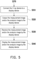
- FIG. 5 is a flowchart of outputting a measurement image and an analysis image according to an embodiment of the disclosure.
- FIG. 6 is a schematic diagram of outputting a measurement image and an analysis image according to an embodiment of the disclosure.
- the X ray device 100 may subsequently perform steps S510 to S540.
- the X ray device 100 may be connected to a display device 600.
- the X ray device 100 may be connected to the display device 600 through a connection wire or through Bluetooth or Wi-Fi.
- the disclosure is not limited thereto.
- the display device 600 may be the electronic device 200 in FIG. 2 or a device that is different from the electronic device 200 in FIG. 2 .
- the measurement image 410 and/or the analysis image 430 are output to the display device 600.
- a control unit of the X ray device 100 may output the measurement image 410 and/or the analysis image 430 to the display device 600.
- the measurement image 410 and/or the analysis image 430 may be received by the display device 600.
- step S540 the measurement image 410 and/or the analysis image 430 may be displayed by the display device 600.
- the X ray device 100 performs image analysis processing on the measurement image 410 before being connected to the display device 600, without a need for the display device 600 to additionally perform an operation related to image analysis processing. Therefore, after the X ray device 100 is connected to the display device 600, the user is able to quickly obtain an X ray measurement result and/or an X ray image analysis result corresponding to a specific measured part through the display device 600. From another point of view, the above-mentioned X ray image processing method may reduce hardware requirements of the display device 600.
- a computing module corresponding to a specific measurement area may be executed to perform an instant image analysis on an obtained measurement image and a corresponding analysis image may be generated.
- the measurement image and/or the analysis image may be transmitted to the display device for display, and thus, the need for external communication and/or external image data processing during an X ray image processing process can be eliminated.
Landscapes
- Engineering & Computer Science (AREA)
- Health & Medical Sciences (AREA)
- Life Sciences & Earth Sciences (AREA)
- Medical Informatics (AREA)
- Physics & Mathematics (AREA)
- Nuclear Medicine, Radiotherapy & Molecular Imaging (AREA)
- General Health & Medical Sciences (AREA)
- Radiology & Medical Imaging (AREA)
- Biomedical Technology (AREA)
- Veterinary Medicine (AREA)
- Pathology (AREA)
- High Energy & Nuclear Physics (AREA)
- Biophysics (AREA)
- Heart & Thoracic Surgery (AREA)
- Molecular Biology (AREA)
- Surgery (AREA)
- Animal Behavior & Ethology (AREA)
- Optics & Photonics (AREA)
- Public Health (AREA)
- Computer Vision & Pattern Recognition (AREA)
- Human Computer Interaction (AREA)
- General Physics & Mathematics (AREA)
- Theoretical Computer Science (AREA)
- Quality & Reliability (AREA)
- Physiology (AREA)
- Apparatus For Radiation Diagnosis (AREA)
Description
- The disclosure generally relates to image processing, and, in particular, to an X ray image processing method.
- Currently, when an X ray flat panel detector (FPD) obtains an X ray image, it needs to send the X ray image to a back end computer apparatus for analysis. In other words, instant X ray image processing is not available in the current X ray flat panel detector and a processing method thereof. Furthermore, if the computer apparatus is too old or bandwidth for data transmission is too small, a processing speed of the X ray image may be affected. In specific cases of application of X ray imaging such as passenger security screening at an airport or other transportation system, and an emergency room examination, in which an instant X ray image is required for detection of, for example, pneumonia or other chest lesions, the current apparatus and processing methods may not suit the needs. Accordingly, there have been awaited development of an X ray flat panel detector and an X ray image processing method that are capable of performing instant image analysis.
- The disclosure is directed to an X ray image processing method which generates an analysis image of an X ray image.
- According to an embodiment of the disclosure, the X ray image processing method of the disclosure includes the following. One of multiple computing modules stored in an X ray device is activated, in which the one of the computing modules corresponds to a measurement area. The measurement area corresponding to the one of the computing modules is measured by an image measurement module, and a measurement signal is produced. The measurement signal is transmitted to a computing unit by the image measurement module. A measurement image is computed by the computing unit according to the measurement signal, and the measurement image is stored in a first storage unit of the X ray device. The one of the computing modules is written to the computing unit. The measurement image is transmitted to the computing unit by the first storage unit. The measurement image is analyzed by the computing unit using the one of the computing modules, and an analysis image is generated.
- In light of the above, in the X ray image processing method of the disclosure, an X ray image is analyzed using a computing module corresponding to a specific measurement area, and a corresponding analysis image is generated.
- Several exemplary embodiments accompanied with figures are described in detail below to further describe the disclosure in details.
-
US2016058406A1 may be considered to disclose a method using an X-ray device, producing a measurement signal, transmitting a measurement signal to a computing unit by a measurement module; computing a measurement image by the computing unit according to the measurement signal and storing the measurement image in a first storage unit of the X-ray device; writing a computing module to the computing unit; transmitting the measurement image to the computing unit by the first storage unit; and analyzing the measurement image by the computing unit using the computing module and generating an analysis image. -
-
FIG. 1 is a schematic block diagram of an X ray device according to an embodiment of the disclosure. -
FIG. 2 is a schematic diagram illustrating communication between a master control device and a display device according to an embodiment of the disclosure. -
FIG. 3 is a flowchart of an X ray image processing method according to an embodiment of the disclosure. -
FIG. 4A is a schematic diagram of a measurement image according to an embodiment of the disclosure. -
FIG. 4B is a schematic diagram of defining a measurement area in a measurement image according to an embodiment of the disclosure. -
FIG. 4C is a schematic diagram of an analysis image according to an embodiment of the disclosure. -
FIG. 5 is a flowchart of outputting a measurement image and an analysis image according to an embodiment of the disclosure. -
FIG. 6 is a schematic diagram of outputting a measurement image and an analysis image according to an embodiment of the disclosure. - Reference will now be made in detail to exemplary embodiments of the disclosure, examples of which are illustrated in the accompanying drawings. Wherever possible, the same reference numerals are used in the drawings and the description to refer to the same or like parts. Note that, to facilitate understanding and for simplicity of illustration, several of the drawings in the disclosure only illustrate a part of an electronic device or a display device, and some particular components are not illustrated based on their actual scale. In addition, the number and size of the elements shown in the drawings are exemplary and are not intended to limit the disclosure.
- Throughout the description and the appended claims, certain terms are used to refer to specific elements. Those skilled in the art should understand that electronic apparatus manufacturers may refer to the same component by different terms. The present specification does not intend to distinguish between components that differ in name but not function. In the following description and the claims, the terms such as "comprise" and "include" are open-ended and should be interpreted as "include but not limited to."
- In some embodiments of the disclosure, the terms related to joining and connecting, like "connect" and "interconnect", may mean a direct contact between two structures, or an indirect contact between two structures via an intervening structure, unless specifically defined. The terms related to joining and connecting may include the cases where both structures are removable or both structures are fixed. In addition, the terms "electrically connect" and "couple" include any direct and indirect electrical connection.
- In the following embodiments, the same or similar elements are denoted with the same or similar reference numerals, and the same description will not be repeated. In addition, features of different embodiments may be arbitrarily mixed or combined as long as the mixture or combination does not violate the spirit of the disclosure or cause any contradiction. In the description or the claims, the terms such as "first" and "second" are used to name different elements or distinguish between different embodiments and ranges, instead of setting an upper/lower limit on the number of components or limiting a manufacturing order or disposition order of the elements.
-
FIG. 1 is a schematic block diagram of an X ray device according to an embodiment of the disclosure. Referring toFIG. 1 , anX ray device 100 may be an X ray flat panel detector (FPD). In particular, theX ray device 100 in the disclosure is, for example, a digital radiography (DR) X ray system for remote backup. TheX ray device 100 may be a mobile image capture device and may be used to obtain a measurement image (for example, an X ray image). TheX ray device 100 includes acontrol unit 110, acomputing unit 120, afirst storage unit 130, asecond storage unit 140, animage measurement module 150, and athird storage unit 160. In this embodiment, thecontrol unit 110 is coupled to thecomputing unit 120, thesecond storage unit 140, and thethird storage unit 160. Thecomputing unit 120 is further coupled to thefirst storage unit 130 and theimage measurement module 150. Thecontrol unit 110 is able to communicate with other electronic devices or electronic units to receive a control signal and/or output image data. In some embodiments of the disclosure,multiple computing modules 141 may be stored in thesecond storage unit 140 of theX ray device 100. Each of thecomputing modules 141 corresponds to a different measurement area (for example, a different human body part), or at least one of thecomputing modules 141 may correspond to multiple different measurement areas. Thecomputing module 141 may be a program, software, or other element which performs a computing function. In other embodiments of the disclosure, theX ray device 100 may not include thethird storage unit 160. - In this embodiment, the
control unit 110 may be a central processing unit (CPU) and may communicate with other electronic devices or electronic units through a wired or wireless communication module. For example, thecontrol unit 110 may be connected to other electronic devices or electronic units through a connection wire or may communicate with other electronic devices or electronic units through Bluetooth or Wi-Fi. Thecomputing unit 120 may be a field programmable gate array (FPGA), a graphics processing unit (GPU), or other appropriate element. Thecomputing unit 120 may be used to receive and execute a module written by thecontrol unit 110 and/or receive a measurement signal transmitted by theimage measurement module 150 and generate a corresponding measurement image. In this embodiment, theimage measurement module 150 may include a measurement instrument array that includes multiple measurement instruments for X ray measurement. When theimage measurement module 150 performs measurement, a measurement target may be placed between an X ray light source and theimage measurement module 150. The X ray light source may illuminate the measurement target, and theimage measurement module 150 may produce the measurement signal and send the measurement signal to thecomputing unit 120. - In this embodiment, the
first storage unit 130 and thethird storage unit 160 may be the same type or different types of storages. Thefirst storage unit 130 and thesecond storage unit 140 may be the same type or different types of storages. For example, thefirst storage unit 130 and thethird storage unit 160 may be dynamic random access memories (DRAMs), and thefirst storage unit 130 and thethird storage unit 160 may be the same memory or different memories that are separately disposed. Thefirst storage unit 130 may be accessed by thecomputing unit 120, and may store the measurement image generated by thecomputing unit 120 according to the measurement signal and/or an analysis image generated by thecomputing unit 120 after analyzing the measurement image. In some embodiments, thefirst storage unit 130 may store a module written by thecontrol unit 110. Thethird storage unit 160 may be accessed by thecontrol unit 110 and may store the measurement image and/or the analysis image. Thesecond storage unit 140 may be a flash memory. Thesecond storage unit 140 may be accessed by thecontrol unit 110 and may store one ormore computing modules 141. -
FIG. 2 is a schematic diagram illustrating communication between a master control device and a display device according to an embodiment of the disclosure. Referring toFIG. 1 and FIG. 2 , in this embodiment, theX ray device 100 may first be connected to (communicate with) to anelectronic device 200, in which theelectronic device 200 may be, for example, a personal computer (PC), a laptop, a tablet, or a smart phone. Also, theelectronic device 200 may output a control signal to theX ray device 100 under user control or automatically. For example, when the user needs to measure and analyze an X ray image of a measurement area of a lung by theX ray device 100, the user may start up theX ray device 100 and connect it to theelectronic device 200. The user may operate theelectronic device 200 to make theelectronic device 200 output a corresponding control signal to theX ray device 100, so as to set theX ray device 100 to execute a measurement module corresponding to the measurement area of the lung. For example, before thecomputing module 141 stored in theX ray device 100 is activated, thecontrol unit 110 of theX ray device 100 receives the control signal. Next, theX ray device 100 and theelectronic device 200 may stop connection therebetween, and the user may move theX ray device 100 to another place to perform image measurement. For example, the control signal may be provided by a device other than theX ray device 100 or may also be provided by a unit other than thecontrol unit 110 disposed in theX ray device 100. The disclosure is not limited thereto. - In addition, in other embodiments of the disclosure, the
X ray device 100 may be set to perform a function of measuring an X ray image. Also, theX ray device 100 may further display a current operation mode by a display screen or an indicator light disposed on a side surface of theX ray device 100. For example, when theX ray device 100 activates the above-mentioned function of analyzing the X ray image, the display screen or the indicator light may be in a first display state. When theX ray device 100 does not activate (or turns off) the above-mentioned function of analyzing the X ray image and performs the function of measuring the X ray image, the display screen or the indicator light may be in a second display state. Alternatively, when theX ray device 100 determines that the measurement image obtained includes the measurement area of the lung that corresponds to the settings, the display screen or the indicator light may be in a third display state. When theX ray device 100 determines that the measurement image obtained does not include the measurement area of the lung that corresponds to the settings, the display screen or the indicator light may be in a fourth display state. Therefore, the user may confirm the current operation mode of theX ray device 100 according to the display screen or the indicator light. -
FIG. 3 is a flowchart of an X ray image processing method according to an embodiment of the disclosure. Referring toFIG. 1 to FIG. 3 , after theX ray device 100 completes the operations as described in the embodiment ofFIG. 2 , theX ray device 100 may perform steps S310 to S370 illustrated inFIG. 3 . In step S310, thecontrol unit 110 may activate one of multiple computing modules stored in an X ray device according to a control signal, in which the one of the computing modules corresponds to a measurement area. Specifically, as shown inFIG. 1 , thecontrol unit 110 may activate thecomputing module 141 stored in thesecond storage unit 140 according to the control signal. Thecontrol unit 110 may first search for a position where thecomputing module 141 is stored in thesecond storage unit 140. In step S320, the measurement area corresponding to the one of the computing modules may be measured by theimage measurement module 150, and a measurement signal may be produced. In step S330, the measurement signal is transmitted to thecomputing unit 120 by theimage measurement module 150. In step S340, a measurement image may be computed by thecomputing unit 120 according to the measurement signal, and the measurement image may be stored in thefirst storage unit 130 of theX ray device 100. Specifically, referring also toFIG. 4A , theimage measurement module 150 may measure a measurement area corresponding to one of thecomputing modules 141 and produce a corresponding measurement signal. Theimage measurement module 150 may send the measurement signal to thecomputing unit 120. Thecomputing unit 120 may compute ameasurement image 410 according to the measurement signal and store themeasurement image 410 in thefirst storage unit 130 of theX ray device 100. - In step S350, the one of the computing modules is written to the
computing unit 120. Specifically, as shown inFIG. 1 , thecontrol unit 110 may write the activated one of thecomputing modules 141 to thecomputing unit 120. In other words, when thecomputing unit 120 is to perform image analysis processing on the measurement image corresponding to a specific measurement area, since thecontrol unit 110 has found the position where thecomputing module 141 is stored in thesecond storage unit 140, thecomputing module 141 may be written to thecomputing unit 120 to be executed. Next, in step S360, the measurement image may be transmitted to thecomputing unit 120 by thefirst storage unit 130. In step S370, the measurement image may be analyzed by the one of thecomputing modules 141, and an analysis image may be generated. Specifically, referring also toFIG. 4B and FIG. 4C , thefirst storage unit 130 may transmit themeasurement image 410 stored therein to thecomputing unit 120, and thecomputing unit 120 may execute one of thecomputing modules 141 and analyze themeasurement image 410. More specifically, thecomputing unit 120 may perform image analysis on ameasurement area 420 in themeasurement image 410. - Note that at least one of the
computing modules 141 may include an algorithm, and the algorithm is for grayscale value calculation on themeasurement image 410. Themeasurement area 420 may be an area corresponding to a lung area. Thecomputing unit 120 may determine themeasurement area 420 in themeasurement image 410. After thecomputing unit 120 performs the image analysis on themeasurement area 420 in themeasurement image 410 by using thecomputing module 141, ananalysis image 430 may be generated. The algorithm may include an artificial intelligence (AI) computation model, a neural network (NN) computation model, or a combination thereof, in which deep learning may be performed and an X ray image of a specific human body part may undergo image analysis and recognition through training. For example, the algorithm may include a U-Net deep learning segregation model or a similar semantic segmentation model. Thecomputing unit 120 may first execute the model mentioned above and determine themeasurement area 420 in themeasurement image 410. Themeasurement image 410 may be a grayscale image, and thecomputing unit 120 may calculate a grayscale value of each pixel in themeasurement image 410. In addition, the algorithm may further include, for example, a deep residual network (ResNet) model and/or a gradient-weighted class activation mapping (GRAD-CAM) model. Thecomputing unit 120 may then execute, for example, the deep residual network model and determine anabnormal part 431 in themeasurement area 420 and execute, for example, the gradient-weighted class activation mapping model and perform heatmap coloring to generate theanalysis image 430. In other words, when themeasurement area 420 of themeasurement image 410 contains theabnormal part 431 such as, for example, an abnormal lung tissue change due to pneumonia, in some embodiments, a pixel in a position corresponding to theabnormal part 431 in theanalysis image 430 may have a specific color distribution, thereby prompting the user or a medical professional to make a medical image diagnosis on the lung tissue corresponding to the position with the specific color distribution in theanalysis image 430. In other embodiments, the position corresponding to theabnormal part 431 in theanalysis image 430 may be shown in different grayscales for the user to make a medical image diagnosis. - In this embodiment, the
measurement image 410 and/or theanalysis image 430 generated by thecomputing unit 120 may be stored in thefirst storage unit 130 or thethird storage unit 160. When theX ray device 100 and the display device are in connection, thecontrol unit 110 may output themeasurement image 410 and/or theanalysis image 430 to the display device for display by accessing thefirst storage unit 130 or thethird storage unit 160. Alternatively, in some embodiments of the disclosure, theX ray device 100 may include the display device that is able to display themeasurement image 410 and/or theanalysis image 430. Accordingly, in the X ray image processing method and/or theX ray device 100 of this embodiment, based on themeasurement image 410, the correspondinganalysis image 430 may be rapidly generated. -
FIG. 5 is a flowchart of outputting a measurement image and an analysis image according to an embodiment of the disclosure.FIG. 6 is a schematic diagram of outputting a measurement image and an analysis image according to an embodiment of the disclosure. Referring toFIG. 5 andFIG. 6 , in some embodiments of the disclosure, after theX ray device 100 completes the image processing and/or analysis operations as described in the embodiment ofFIG. 3 , theX ray device 100 may subsequently perform steps S510 to S540. In step S510, theX ray device 100 may be connected to adisplay device 600. For example, theX ray device 100 may be connected to thedisplay device 600 through a connection wire or through Bluetooth or Wi-Fi. However, the disclosure is not limited thereto. Thedisplay device 600 may be theelectronic device 200 inFIG. 2 or a device that is different from theelectronic device 200 inFIG. 2 . In step S520, themeasurement image 410 and/or theanalysis image 430 are output to thedisplay device 600. As shown inFIG. 6 , after a computing unit of theX ray device 100 generates an analysis image, a control unit of theX ray device 100 may output themeasurement image 410 and/or theanalysis image 430 to thedisplay device 600. In step S530, themeasurement image 410 and/or theanalysis image 430 may be received by thedisplay device 600. In step S540, themeasurement image 410 and/or theanalysis image 430 may be displayed by thedisplay device 600. - Accordingly, the
X ray device 100 performs image analysis processing on themeasurement image 410 before being connected to thedisplay device 600, without a need for thedisplay device 600 to additionally perform an operation related to image analysis processing. Therefore, after theX ray device 100 is connected to thedisplay device 600, the user is able to quickly obtain an X ray measurement result and/or an X ray image analysis result corresponding to a specific measured part through thedisplay device 600. From another point of view, the above-mentioned X ray image processing method may reduce hardware requirements of thedisplay device 600. - In summary, in the X ray image processing method in the disclosure, a computing module corresponding to a specific measurement area may be executed to perform an instant image analysis on an obtained measurement image and a corresponding analysis image may be generated. In the X ray image processing method in the disclosure, the measurement image and/or the analysis image may be transmitted to the display device for display, and thus, the need for external communication and/or external image data processing during an X ray image processing process can be eliminated.
Claims (15)
- An X ray image processing method, comprising:activating one of a plurality of computing modules (141) stored in an X ray device (100), wherein the one of the plurality of computing modules (141) corresponds to a measurement area (420);measuring the measurement area (420) corresponding to the one of the plurality of computing modules (141) by an image measurement module (150) and producing a measurement signal;transmitting the measurement signal to a computing unit (120) by the image measurement module (150);computing a measurement image (410) by the computing unit (120) according to the measurement signal and storing the measurement image (410) in a first storage unit (130) of the X ray device (100);writing the one of the plurality of computing modules (141) to the computing unit (120);transmitting the measurement image (410) to the computing unit (120) by the first storage unit (130); andanalyzing the measurement image (410) by the computing unit (120) using the one of the plurality of computing modules (141) and generating an analysis image (430).
- The X ray image processing method according to claim 1, comprising, after generating the analysis image (430) by the computing unit (120), outputting the measurement image (410) and the analysis image (430).
- The X ray image processing method according to claim 2, further comprising:outputting the measurement image (410) and the analysis image (430) to a display device (600); anddisplaying the measurement image (410) and the analysis image (430) by the display device (600).
- The X ray image processing method according to claim 1, wherein the plurality of computing modules (141) are stored in a second storage unit (140) of the X ray device (100).
- The X ray image processing method according to claim 4, wherein the first storage unit (130) and the second storage unit (140) are different types of storages.
- The X ray image processing method according to claim 1, wherein a control unit (110) of the X ray device (100) activates the one of the plurality of computing modules (141).
- The X ray image processing method according to claim 1, comprising, before activating the one of the plurality of computing modules (141) stored in the X ray device (100), receiving a control signal by a control unit (110) of the X ray device (100).
- The X ray image processing method according to claim 1, wherein the one of the plurality of computing modules (141) comprises an algorithm, and the algorithm is for grayscale value calculation on the measurement image (410).
- The X ray image processing method according to claim 1, wherein the measurement area (420) corresponds to a lung area.
- The X ray image processing method according to claim 1, wherein the X ray device (100) is an X ray flat panel detector.
- The X ray image processing method according to claim 1, wherein analyzing the measurement image (410) by the computing unit (120) using the one of the plurality of computing modules (141) and generating the analysis image (430) comprises:executing a U-Net deep learning segregation model or a similar semantic segmentation model by the computing unit (120) to determine the measurement area (420) in the measurement image (410);calculating a grayscale value of each pixel in the measurement image (410) by the computing unit (120) to execute a deep residual network model and determine an abnormal part (431) in the measurement area (420); andexecuting a gradient-weighted class activation mapping model and performing heatmap coloring to generate the analysis image (430).
- The X ray image processing method according to claim 11, wherein a pixel in a position corresponding to the abnormal part (431) in the analysis image (430) has a specific color distribution.
- The X ray image processing method according to claim 11, wherein the measurement image (410) is a grayscale image.
- The X ray image processing method according to claim 11, wherein a pixel in a position corresponding to the abnormal part (431) in the analysis image (430) is shown in different grayscales.
- The X ray image processing method according to claim 1, further comprising:
displaying a current operation mode by a display screen or an indicator light disposed on a side surface of the X ray device (100).
Applications Claiming Priority (1)
| Application Number | Priority Date | Filing Date | Title |
|---|---|---|---|
| CN202110348522.0A CN115137377B (en) | 2021-03-31 | 2021-03-31 | X-ray image processing methods |
Publications (2)
| Publication Number | Publication Date |
|---|---|
| EP4066743A1 EP4066743A1 (en) | 2022-10-05 |
| EP4066743B1 true EP4066743B1 (en) | 2024-02-28 |
Family
ID=80625510
Family Applications (1)
| Application Number | Title | Priority Date | Filing Date |
|---|---|---|---|
| EP22159856.8A Active EP4066743B1 (en) | 2021-03-31 | 2022-03-03 | X ray image processing method |
Country Status (3)
| Country | Link |
|---|---|
| US (1) | US12193863B2 (en) |
| EP (1) | EP4066743B1 (en) |
| CN (1) | CN115137377B (en) |
Family Cites Families (9)
| Publication number | Priority date | Publication date | Assignee | Title |
|---|---|---|---|---|
| JP2007082729A (en) * | 2005-09-22 | 2007-04-05 | Hitachi Medical Corp | X-ray diagnostic imaging apparatus |
| US8284208B2 (en) * | 2006-05-24 | 2012-10-09 | General Electric Company | Processes and apparatus for information transfer |
| CN104095644B (en) * | 2013-04-03 | 2019-05-03 | 锐珂(上海)医疗器材有限公司 | Multimodal digital radiography system and imaging method therefor |
| KR102076527B1 (en) * | 2014-08-27 | 2020-04-02 | 삼성전자주식회사 | A radiographic imaging apparatus and a method for controlling the same |
| CN204515353U (en) | 2015-03-31 | 2015-07-29 | 深圳市长桑技术有限公司 | A kind of intelligent watch |
| CN205229072U (en) * | 2015-12-07 | 2016-05-11 | 苏州科耐视智能科技有限公司 | Target defect detecting device based on X ray |
| CN107495978B (en) * | 2017-09-20 | 2021-01-12 | 上海联影医疗科技股份有限公司 | X-ray photography system and image acquisition method |
| US11869121B2 (en) * | 2018-06-29 | 2024-01-09 | Shanghai United Imaging Healthcare Co., Ltd. | Systems and methods for image reconstruction |
| US11436716B2 (en) | 2019-04-19 | 2022-09-06 | Canon Kabushiki Kaisha | Electronic apparatus, analysis system and control method of electronic apparatus |
-
2021
- 2021-03-31 CN CN202110348522.0A patent/CN115137377B/en active Active
-
2022
- 2022-03-03 US US17/685,399 patent/US12193863B2/en active Active
- 2022-03-03 EP EP22159856.8A patent/EP4066743B1/en active Active
Also Published As
| Publication number | Publication date |
|---|---|
| US20220313194A1 (en) | 2022-10-06 |
| CN115137377B (en) | 2025-10-28 |
| CN115137377A (en) | 2022-10-04 |
| US12193863B2 (en) | 2025-01-14 |
| EP4066743A1 (en) | 2022-10-05 |
Similar Documents
| Publication | Publication Date | Title |
|---|---|---|
| CN111598900B (en) | Image region segmentation model training method, segmentation method and device | |
| US10755411B2 (en) | Method and apparatus for annotating medical image | |
| US11900594B2 (en) | Methods and systems for displaying a region of interest of a medical image | |
| EP3998579B1 (en) | Medical image processing method, apparatus and device, medium and endoscope | |
| CA3110581A1 (en) | System and method for evaluating the performance of a user in capturing an image of an anatomical region | |
| US20220148172A1 (en) | System and method for detecting medical conditions | |
| US20210192718A1 (en) | Methods and systems for automatic measurement of strains and strain-ratio calculation for sonoelastography | |
| CN113269849B (en) | Method and device for reconstructing magnetic resonance | |
| KR102123598B1 (en) | Apparatus and system for skin diagnosis and method thereof | |
| EP4066743A1 (en) | X ray image processing method | |
| CN111612865B (en) | MRI (magnetic resonance imaging) method and device for generating countermeasure network based on conditions | |
| KR20250069510A (en) | Method for segmenting medical image information and apparatus for performing the same | |
| KR20250070022A (en) | Method for segmenting medical image and apparatus for performing the same | |
| CN117316082A (en) | Display control methods, devices, equipment, media and products | |
| CN113793422A (en) | Display control method of three-dimensional model, electronic device and readable storage medium | |
| CN115861298B (en) | Image processing method and device based on endoscopic visualization | |
| CN112270974A (en) | A kind of intelligent auxiliary medical imaging workstation based on artificial intelligence | |
| CN112426170A (en) | Placenta thickness determination method, device, equipment and storage medium | |
| CN112545485B (en) | A magnetic resonance scanning method, device, equipment and storage medium | |
| KR20240092417A (en) | Electronic apparatus and method for controlling thereof | |
| CN112669450A (en) | Human body model construction method and personalized human body model construction method | |
| CN113764072B (en) | Medical image reconstruction method, device, equipment and storage medium | |
| CN121032881A (en) | Visual field meter luminance calibration method, visual field measurement method, system and storage medium | |
| CN117238454B (en) | Medical image processing methods, devices and computer equipment | |
| US20240389983A1 (en) | Wearable fertility prediction device |
Legal Events
| Date | Code | Title | Description |
|---|---|---|---|
| PUAI | Public reference made under article 153(3) epc to a published international application that has entered the european phase |
Free format text: ORIGINAL CODE: 0009012 |
|
| STAA | Information on the status of an ep patent application or granted ep patent |
Free format text: STATUS: THE APPLICATION HAS BEEN PUBLISHED |
|
| AK | Designated contracting states |
Kind code of ref document: A1 Designated state(s): AL AT BE BG CH CY CZ DE DK EE ES FI FR GB GR HR HU IE IS IT LI LT LU LV MC MK MT NL NO PL PT RO RS SE SI SK SM TR |
|
| STAA | Information on the status of an ep patent application or granted ep patent |
Free format text: STATUS: REQUEST FOR EXAMINATION WAS MADE |
|
| 17P | Request for examination filed |
Effective date: 20230315 |
|
| RBV | Designated contracting states (corrected) |
Designated state(s): AL AT BE BG CH CY CZ DE DK EE ES FI FR GB GR HR HU IE IS IT LI LT LU LV MC MK MT NL NO PL PT RO RS SE SI SK SM TR |
|
| GRAP | Despatch of communication of intention to grant a patent |
Free format text: ORIGINAL CODE: EPIDOSNIGR1 |
|
| STAA | Information on the status of an ep patent application or granted ep patent |
Free format text: STATUS: GRANT OF PATENT IS INTENDED |
|
| INTG | Intention to grant announced |
Effective date: 20230927 |
|
| GRAS | Grant fee paid |
Free format text: ORIGINAL CODE: EPIDOSNIGR3 |
|
| GRAA | (expected) grant |
Free format text: ORIGINAL CODE: 0009210 |
|
| STAA | Information on the status of an ep patent application or granted ep patent |
Free format text: STATUS: THE PATENT HAS BEEN GRANTED |
|
| AK | Designated contracting states |
Kind code of ref document: B1 Designated state(s): AL AT BE BG CH CY CZ DE DK EE ES FI FR GB GR HR HU IE IS IT LI LT LU LV MC MK MT NL NO PL PT RO RS SE SI SK SM TR |
|
| REG | Reference to a national code |
Ref country code: GB Ref legal event code: FG4D |
|
| REG | Reference to a national code |
Ref country code: CH Ref legal event code: EP |
|
| REG | Reference to a national code |
Ref country code: DE Ref legal event code: R096 Ref document number: 602022002090 Country of ref document: DE |
|
| REG | Reference to a national code |
Ref country code: IE Ref legal event code: FG4D |
|
| REG | Reference to a national code |
Ref country code: LT Ref legal event code: MG9D |
|
| PG25 | Lapsed in a contracting state [announced via postgrant information from national office to epo] |
Ref country code: IS Free format text: LAPSE BECAUSE OF FAILURE TO SUBMIT A TRANSLATION OF THE DESCRIPTION OR TO PAY THE FEE WITHIN THE PRESCRIBED TIME-LIMIT Effective date: 20240628 |
|
| REG | Reference to a national code |
Ref country code: NL Ref legal event code: MP Effective date: 20240228 |
|
| PG25 | Lapsed in a contracting state [announced via postgrant information from national office to epo] |
Ref country code: LT Free format text: LAPSE BECAUSE OF FAILURE TO SUBMIT A TRANSLATION OF THE DESCRIPTION OR TO PAY THE FEE WITHIN THE PRESCRIBED TIME-LIMIT Effective date: 20240228 |
|
| PG25 | Lapsed in a contracting state [announced via postgrant information from national office to epo] |
Ref country code: GR Free format text: LAPSE BECAUSE OF FAILURE TO SUBMIT A TRANSLATION OF THE DESCRIPTION OR TO PAY THE FEE WITHIN THE PRESCRIBED TIME-LIMIT Effective date: 20240529 |
|
| PG25 | Lapsed in a contracting state [announced via postgrant information from national office to epo] |
Ref country code: NL Free format text: LAPSE BECAUSE OF FAILURE TO SUBMIT A TRANSLATION OF THE DESCRIPTION OR TO PAY THE FEE WITHIN THE PRESCRIBED TIME-LIMIT Effective date: 20240228 Ref country code: HR Free format text: LAPSE BECAUSE OF FAILURE TO SUBMIT A TRANSLATION OF THE DESCRIPTION OR TO PAY THE FEE WITHIN THE PRESCRIBED TIME-LIMIT Effective date: 20240228 Ref country code: RS Free format text: LAPSE BECAUSE OF FAILURE TO SUBMIT A TRANSLATION OF THE DESCRIPTION OR TO PAY THE FEE WITHIN THE PRESCRIBED TIME-LIMIT Effective date: 20240528 |
|
| PG25 | Lapsed in a contracting state [announced via postgrant information from national office to epo] |
Ref country code: ES Free format text: LAPSE BECAUSE OF FAILURE TO SUBMIT A TRANSLATION OF THE DESCRIPTION OR TO PAY THE FEE WITHIN THE PRESCRIBED TIME-LIMIT Effective date: 20240228 |
|
| PG25 | Lapsed in a contracting state [announced via postgrant information from national office to epo] |
Ref country code: RS Free format text: LAPSE BECAUSE OF FAILURE TO SUBMIT A TRANSLATION OF THE DESCRIPTION OR TO PAY THE FEE WITHIN THE PRESCRIBED TIME-LIMIT Effective date: 20240528 Ref country code: NO Free format text: LAPSE BECAUSE OF FAILURE TO SUBMIT A TRANSLATION OF THE DESCRIPTION OR TO PAY THE FEE WITHIN THE PRESCRIBED TIME-LIMIT Effective date: 20240528 Ref country code: NL Free format text: LAPSE BECAUSE OF FAILURE TO SUBMIT A TRANSLATION OF THE DESCRIPTION OR TO PAY THE FEE WITHIN THE PRESCRIBED TIME-LIMIT Effective date: 20240228 Ref country code: LT Free format text: LAPSE BECAUSE OF FAILURE TO SUBMIT A TRANSLATION OF THE DESCRIPTION OR TO PAY THE FEE WITHIN THE PRESCRIBED TIME-LIMIT Effective date: 20240228 Ref country code: IS Free format text: LAPSE BECAUSE OF FAILURE TO SUBMIT A TRANSLATION OF THE DESCRIPTION OR TO PAY THE FEE WITHIN THE PRESCRIBED TIME-LIMIT Effective date: 20240628 Ref country code: HR Free format text: LAPSE BECAUSE OF FAILURE TO SUBMIT A TRANSLATION OF THE DESCRIPTION OR TO PAY THE FEE WITHIN THE PRESCRIBED TIME-LIMIT Effective date: 20240228 Ref country code: GR Free format text: LAPSE BECAUSE OF FAILURE TO SUBMIT A TRANSLATION OF THE DESCRIPTION OR TO PAY THE FEE WITHIN THE PRESCRIBED TIME-LIMIT Effective date: 20240529 Ref country code: FI Free format text: LAPSE BECAUSE OF FAILURE TO SUBMIT A TRANSLATION OF THE DESCRIPTION OR TO PAY THE FEE WITHIN THE PRESCRIBED TIME-LIMIT Effective date: 20240228 Ref country code: ES Free format text: LAPSE BECAUSE OF FAILURE TO SUBMIT A TRANSLATION OF THE DESCRIPTION OR TO PAY THE FEE WITHIN THE PRESCRIBED TIME-LIMIT Effective date: 20240228 Ref country code: BG Free format text: LAPSE BECAUSE OF FAILURE TO SUBMIT A TRANSLATION OF THE DESCRIPTION OR TO PAY THE FEE WITHIN THE PRESCRIBED TIME-LIMIT Effective date: 20240228 |
|
| PG25 | Lapsed in a contracting state [announced via postgrant information from national office to epo] |
Ref country code: PL Free format text: LAPSE BECAUSE OF FAILURE TO SUBMIT A TRANSLATION OF THE DESCRIPTION OR TO PAY THE FEE WITHIN THE PRESCRIBED TIME-LIMIT Effective date: 20240228 Ref country code: PT Free format text: LAPSE BECAUSE OF FAILURE TO SUBMIT A TRANSLATION OF THE DESCRIPTION OR TO PAY THE FEE WITHIN THE PRESCRIBED TIME-LIMIT Effective date: 20240628 |
|
| REG | Reference to a national code |
Ref country code: AT Ref legal event code: MK05 Ref document number: 1660447 Country of ref document: AT Kind code of ref document: T Effective date: 20240228 |
|
| PG25 | Lapsed in a contracting state [announced via postgrant information from national office to epo] |
Ref country code: SE Free format text: LAPSE BECAUSE OF FAILURE TO SUBMIT A TRANSLATION OF THE DESCRIPTION OR TO PAY THE FEE WITHIN THE PRESCRIBED TIME-LIMIT Effective date: 20240228 Ref country code: PT Free format text: LAPSE BECAUSE OF FAILURE TO SUBMIT A TRANSLATION OF THE DESCRIPTION OR TO PAY THE FEE WITHIN THE PRESCRIBED TIME-LIMIT Effective date: 20240628 Ref country code: PL Free format text: LAPSE BECAUSE OF FAILURE TO SUBMIT A TRANSLATION OF THE DESCRIPTION OR TO PAY THE FEE WITHIN THE PRESCRIBED TIME-LIMIT Effective date: 20240228 Ref country code: LV Free format text: LAPSE BECAUSE OF FAILURE TO SUBMIT A TRANSLATION OF THE DESCRIPTION OR TO PAY THE FEE WITHIN THE PRESCRIBED TIME-LIMIT Effective date: 20240228 |
|
| PG25 | Lapsed in a contracting state [announced via postgrant information from national office to epo] |
Ref country code: DK Free format text: LAPSE BECAUSE OF FAILURE TO SUBMIT A TRANSLATION OF THE DESCRIPTION OR TO PAY THE FEE WITHIN THE PRESCRIBED TIME-LIMIT Effective date: 20240228 |
|
| PG25 | Lapsed in a contracting state [announced via postgrant information from national office to epo] |
Ref country code: SM Free format text: LAPSE BECAUSE OF FAILURE TO SUBMIT A TRANSLATION OF THE DESCRIPTION OR TO PAY THE FEE WITHIN THE PRESCRIBED TIME-LIMIT Effective date: 20240228 |
|
| PG25 | Lapsed in a contracting state [announced via postgrant information from national office to epo] |
Ref country code: CZ Free format text: LAPSE BECAUSE OF FAILURE TO SUBMIT A TRANSLATION OF THE DESCRIPTION OR TO PAY THE FEE WITHIN THE PRESCRIBED TIME-LIMIT Effective date: 20240228 Ref country code: EE Free format text: LAPSE BECAUSE OF FAILURE TO SUBMIT A TRANSLATION OF THE DESCRIPTION OR TO PAY THE FEE WITHIN THE PRESCRIBED TIME-LIMIT Effective date: 20240228 |
|
| PG25 | Lapsed in a contracting state [announced via postgrant information from national office to epo] |
Ref country code: AT Free format text: LAPSE BECAUSE OF FAILURE TO SUBMIT A TRANSLATION OF THE DESCRIPTION OR TO PAY THE FEE WITHIN THE PRESCRIBED TIME-LIMIT Effective date: 20240228 |
|
| PG25 | Lapsed in a contracting state [announced via postgrant information from national office to epo] |
Ref country code: SK Free format text: LAPSE BECAUSE OF FAILURE TO SUBMIT A TRANSLATION OF THE DESCRIPTION OR TO PAY THE FEE WITHIN THE PRESCRIBED TIME-LIMIT Effective date: 20240228 |
|
| PG25 | Lapsed in a contracting state [announced via postgrant information from national office to epo] |
Ref country code: SM Free format text: LAPSE BECAUSE OF FAILURE TO SUBMIT A TRANSLATION OF THE DESCRIPTION OR TO PAY THE FEE WITHIN THE PRESCRIBED TIME-LIMIT Effective date: 20240228 Ref country code: SK Free format text: LAPSE BECAUSE OF FAILURE TO SUBMIT A TRANSLATION OF THE DESCRIPTION OR TO PAY THE FEE WITHIN THE PRESCRIBED TIME-LIMIT Effective date: 20240228 Ref country code: RO Free format text: LAPSE BECAUSE OF FAILURE TO SUBMIT A TRANSLATION OF THE DESCRIPTION OR TO PAY THE FEE WITHIN THE PRESCRIBED TIME-LIMIT Effective date: 20240228 Ref country code: EE Free format text: LAPSE BECAUSE OF FAILURE TO SUBMIT A TRANSLATION OF THE DESCRIPTION OR TO PAY THE FEE WITHIN THE PRESCRIBED TIME-LIMIT Effective date: 20240228 Ref country code: DK Free format text: LAPSE BECAUSE OF FAILURE TO SUBMIT A TRANSLATION OF THE DESCRIPTION OR TO PAY THE FEE WITHIN THE PRESCRIBED TIME-LIMIT Effective date: 20240228 Ref country code: CZ Free format text: LAPSE BECAUSE OF FAILURE TO SUBMIT A TRANSLATION OF THE DESCRIPTION OR TO PAY THE FEE WITHIN THE PRESCRIBED TIME-LIMIT Effective date: 20240228 Ref country code: AT Free format text: LAPSE BECAUSE OF FAILURE TO SUBMIT A TRANSLATION OF THE DESCRIPTION OR TO PAY THE FEE WITHIN THE PRESCRIBED TIME-LIMIT Effective date: 20240228 |
|
| PG25 | Lapsed in a contracting state [announced via postgrant information from national office to epo] |
Ref country code: LU Free format text: LAPSE BECAUSE OF NON-PAYMENT OF DUE FEES Effective date: 20240303 |
|
| PG25 | Lapsed in a contracting state [announced via postgrant information from national office to epo] |
Ref country code: MC Free format text: LAPSE BECAUSE OF FAILURE TO SUBMIT A TRANSLATION OF THE DESCRIPTION OR TO PAY THE FEE WITHIN THE PRESCRIBED TIME-LIMIT Effective date: 20240228 |
|
| PG25 | Lapsed in a contracting state [announced via postgrant information from national office to epo] |
Ref country code: MC Free format text: LAPSE BECAUSE OF FAILURE TO SUBMIT A TRANSLATION OF THE DESCRIPTION OR TO PAY THE FEE WITHIN THE PRESCRIBED TIME-LIMIT Effective date: 20240228 Ref country code: LU Free format text: LAPSE BECAUSE OF NON-PAYMENT OF DUE FEES Effective date: 20240303 |
|
| REG | Reference to a national code |
Ref country code: DE Ref legal event code: R097 Ref document number: 602022002090 Country of ref document: DE |
|
| PG25 | Lapsed in a contracting state [announced via postgrant information from national office to epo] |
Ref country code: IT Free format text: LAPSE BECAUSE OF FAILURE TO SUBMIT A TRANSLATION OF THE DESCRIPTION OR TO PAY THE FEE WITHIN THE PRESCRIBED TIME-LIMIT Effective date: 20240228 |
|
| REG | Reference to a national code |
Ref country code: BE Ref legal event code: MM Effective date: 20240331 |
|
| PG25 | Lapsed in a contracting state [announced via postgrant information from national office to epo] |
Ref country code: IT Free format text: LAPSE BECAUSE OF FAILURE TO SUBMIT A TRANSLATION OF THE DESCRIPTION OR TO PAY THE FEE WITHIN THE PRESCRIBED TIME-LIMIT Effective date: 20240228 |
|
| PLBE | No opposition filed within time limit |
Free format text: ORIGINAL CODE: 0009261 |
|
| STAA | Information on the status of an ep patent application or granted ep patent |
Free format text: STATUS: NO OPPOSITION FILED WITHIN TIME LIMIT |
|
| PG25 | Lapsed in a contracting state [announced via postgrant information from national office to epo] |
Ref country code: BE Free format text: LAPSE BECAUSE OF NON-PAYMENT OF DUE FEES Effective date: 20240331 |
|
| PG25 | Lapsed in a contracting state [announced via postgrant information from national office to epo] |
Ref country code: IE Free format text: LAPSE BECAUSE OF NON-PAYMENT OF DUE FEES Effective date: 20240303 |
|
| PG25 | Lapsed in a contracting state [announced via postgrant information from national office to epo] |
Ref country code: IE Free format text: LAPSE BECAUSE OF NON-PAYMENT OF DUE FEES Effective date: 20240303 Ref country code: BE Free format text: LAPSE BECAUSE OF NON-PAYMENT OF DUE FEES Effective date: 20240331 |
|
| 26N | No opposition filed |
Effective date: 20241129 |
|
| PG25 | Lapsed in a contracting state [announced via postgrant information from national office to epo] |
Ref country code: SI Free format text: LAPSE BECAUSE OF FAILURE TO SUBMIT A TRANSLATION OF THE DESCRIPTION OR TO PAY THE FEE WITHIN THE PRESCRIBED TIME-LIMIT Effective date: 20240228 |
|
| PG25 | Lapsed in a contracting state [announced via postgrant information from national office to epo] |
Ref country code: CY Free format text: LAPSE BECAUSE OF FAILURE TO SUBMIT A TRANSLATION OF THE DESCRIPTION OR TO PAY THE FEE WITHIN THE PRESCRIBED TIME-LIMIT; INVALID AB INITIO Effective date: 20220303 |
|
| REG | Reference to a national code |
Ref country code: CH Ref legal event code: H13 Free format text: ST27 STATUS EVENT CODE: U-0-0-H10-H13 (AS PROVIDED BY THE NATIONAL OFFICE) Effective date: 20251023 |
|
| PG25 | Lapsed in a contracting state [announced via postgrant information from national office to epo] |
Ref country code: TR Free format text: LAPSE BECAUSE OF FAILURE TO SUBMIT A TRANSLATION OF THE DESCRIPTION OR TO PAY THE FEE WITHIN THE PRESCRIBED TIME-LIMIT Effective date: 20240228 |
|
| PG25 | Lapsed in a contracting state [announced via postgrant information from national office to epo] |
Ref country code: CH Free format text: LAPSE BECAUSE OF NON-PAYMENT OF DUE FEES Effective date: 20250331 |
|
| PGFP | Annual fee paid to national office [announced via postgrant information from national office to epo] |
Ref country code: GB Payment date: 20260327 Year of fee payment: 5 |
|
| PGFP | Annual fee paid to national office [announced via postgrant information from national office to epo] |
Ref country code: DE Payment date: 20260327 Year of fee payment: 5 |
|
| PGFP | Annual fee paid to national office [announced via postgrant information from national office to epo] |
Ref country code: FR Payment date: 20260325 Year of fee payment: 5 |
|
| PG25 | Lapsed in a contracting state [announced via postgrant information from national office to epo] |
Ref country code: CH Free format text: THE PATENT HAS BEEN ANNULLED BY A DECISION OF A NATIONAL AUTHORITY Effective date: 20250331 |