EP4066742A1 - Radiographic system, radiographic method, and program - Google Patents
Radiographic system, radiographic method, and program Download PDFInfo
- Publication number
- EP4066742A1 EP4066742A1 EP22159253.8A EP22159253A EP4066742A1 EP 4066742 A1 EP4066742 A1 EP 4066742A1 EP 22159253 A EP22159253 A EP 22159253A EP 4066742 A1 EP4066742 A1 EP 4066742A1
- Authority
- EP
- European Patent Office
- Prior art keywords
- radiographic
- radiation
- dose
- value
- information
- Prior art date
- Legal status (The legal status is an assumption and is not a legal conclusion. Google has not performed a legal analysis and makes no representation as to the accuracy of the status listed.)
- Granted
Links
Images






Classifications
-
- A—HUMAN NECESSITIES
- A61—MEDICAL OR VETERINARY SCIENCE; HYGIENE
- A61B—DIAGNOSIS; SURGERY; IDENTIFICATION
- A61B6/00—Apparatus or devices for radiation diagnosis; Apparatus or devices for radiation diagnosis combined with radiation therapy equipment
- A61B6/54—Control of apparatus or devices for radiation diagnosis
- A61B6/542—Control of apparatus or devices for radiation diagnosis involving control of exposure
-
- A—HUMAN NECESSITIES
- A61—MEDICAL OR VETERINARY SCIENCE; HYGIENE
- A61B—DIAGNOSIS; SURGERY; IDENTIFICATION
- A61B6/00—Apparatus or devices for radiation diagnosis; Apparatus or devices for radiation diagnosis combined with radiation therapy equipment
- A61B6/42—Arrangements for detecting radiation specially adapted for radiation diagnosis
-
- A—HUMAN NECESSITIES
- A61—MEDICAL OR VETERINARY SCIENCE; HYGIENE
- A61B—DIAGNOSIS; SURGERY; IDENTIFICATION
- A61B6/00—Apparatus or devices for radiation diagnosis; Apparatus or devices for radiation diagnosis combined with radiation therapy equipment
- A61B6/42—Arrangements for detecting radiation specially adapted for radiation diagnosis
- A61B6/4266—Arrangements for detecting radiation specially adapted for radiation diagnosis characterised by using a plurality of detector units
-
- A—HUMAN NECESSITIES
- A61—MEDICAL OR VETERINARY SCIENCE; HYGIENE
- A61B—DIAGNOSIS; SURGERY; IDENTIFICATION
- A61B6/00—Apparatus or devices for radiation diagnosis; Apparatus or devices for radiation diagnosis combined with radiation therapy equipment
- A61B6/46—Arrangements for interfacing with the operator or the patient
- A61B6/461—Displaying means of special interest
-
- A—HUMAN NECESSITIES
- A61—MEDICAL OR VETERINARY SCIENCE; HYGIENE
- A61B—DIAGNOSIS; SURGERY; IDENTIFICATION
- A61B6/00—Apparatus or devices for radiation diagnosis; Apparatus or devices for radiation diagnosis combined with radiation therapy equipment
- A61B6/46—Arrangements for interfacing with the operator or the patient
- A61B6/461—Displaying means of special interest
- A61B6/465—Displaying means of special interest adapted to display user selection data, e.g. graphical user interface, icons or menus
-
- A—HUMAN NECESSITIES
- A61—MEDICAL OR VETERINARY SCIENCE; HYGIENE
- A61B—DIAGNOSIS; SURGERY; IDENTIFICATION
- A61B6/00—Apparatus or devices for radiation diagnosis; Apparatus or devices for radiation diagnosis combined with radiation therapy equipment
- A61B6/52—Devices using data or image processing specially adapted for radiation diagnosis
- A61B6/5205—Devices using data or image processing specially adapted for radiation diagnosis involving processing of raw data to produce diagnostic data
-
- A—HUMAN NECESSITIES
- A61—MEDICAL OR VETERINARY SCIENCE; HYGIENE
- A61B—DIAGNOSIS; SURGERY; IDENTIFICATION
- A61B6/00—Apparatus or devices for radiation diagnosis; Apparatus or devices for radiation diagnosis combined with radiation therapy equipment
- A61B6/54—Control of apparatus or devices for radiation diagnosis
-
- H—ELECTRICITY
- H04—ELECTRIC COMMUNICATION TECHNIQUE
- H04N—PICTORIAL COMMUNICATION, e.g. TELEVISION
- H04N23/00—Cameras or camera modules comprising electronic image sensors; Control thereof
- H04N23/30—Cameras or camera modules comprising electronic image sensors; Control thereof for generating image signals from X-rays
Definitions
- the present invention relates to a radiographic system, a radiographic method, and a program.
- radiographic apparatuses for use in medical image diagnosis and nondestructive inspection using radiation such as X-rays
- radiographic apparatuses that include a matrix substrate including a pixel array formed by combining switches, like thin-film transistors (TFTs), with conversion elements, like photoelectric conversion elements, have been put to practical use.
- switches like thin-film transistors (TFTs)
- conversion elements like photoelectric conversion elements
- Radiographic apparatuses multifunctional.
- One of the approaches is to implement a built-in function for monitoring radiation irradiation. Such a function enables, for example, detection of a timing of starting radiation irradiation from a radiation source, detection of a timing of stopping the radiation irradiation, and detection of a radiation dosage or a cumulative dosage.
- Japanese Patent No. 4217505 discusses a radiographic system including a radiographic apparatus, a radiation source, and an image control apparatus.
- the radiographic apparatus includes pixels for monitoring radiation irradiation.
- the radiographic apparatus detects a timing of stopping irradiation, the radiographic apparatus transmits an irradiation stop signal to a radiation generation apparatus.
- Japanese Patent No. 4217505 does not discuss specific control signals
- the conventional radiation exposure control is performed by inputting an analog signal from a radiation receiving portion of an ion chamber or a photo timer into an exposure control unit inside the radiation generation apparatus. In response to detection of an integrated value of the analog signal and the like exceeding a predetermined threshold, the radiations are stopped, whereby automatic exposure control (AEC) is performed for dose control.
- AEC automatic exposure control
- the dose index value is a numerical representation of the radiation dose received by the radiographic image detection apparatus.
- EI exposure index
- the dose index is a value for evaluating a dose used in radiographic imaging.
- EI is an index standardized by the International Electric Conference (IEC) as IEC 62494-1. Specifically, an area to calculate an EI value in a radiographic image is determined, and a representative value is extracted from among pixel values of pixels in the calculation area. A predetermined conversion is then performed on the extracted representative value, and the resulting dose index value is displayed.
- EI information is managed and an EI value determined to be an optimum dose for radiographic images (for example, a minimum dose with satisfactory image quality) is set as a target value (Target Exposure Index) EIt. Determination of whether a dose is excessive or insufficient is then performed using a deviation (Deviation Index) DI between a calculated EI value and EIt to facilitate optimum imaging.
- a radiographic system as specified in claims 1 to 13.
- a radiographic method as specified in claim 14.
- a program as specified in claim 15.
- radiographic imaging is typically performed on measuring fields set at both lungs.
- AEC automatic exposure control
- radiographic imaging is typically performed on measuring fields set at both lungs.
- an irradiation dose in the radiation irradiation can be reduced. Consequently, it is desirable that an exposure index (EI) value and a target value EIt are displayed or set based on the measuring fields.
- Exemplary embodiments of the present invention have been achieved in view of the foregoing issue, and are directed to providing a radiographic system where an operator can appropriately determine whether a desirable amount of radiation is incident on measuring fields during radiographic imaging using AEC.
- the present exemplary embodiments can also be directed to providing operations and effects that are derived from configurations described below and not obtainable by the conventional art.
- Fig. 1 is a diagram illustrating a radiographic system according to the present exemplary embodiment.
- a radiographic system 10 is disposed in a radiation chamber 1 where radiographic imaging using radiation irradiation is performed and a control chamber 2 in the vicinity of the radiation chamber 1.
- the radiation chamber 1 includes, as the radiographic system 10, a radiographic apparatus 300, an upright stand 302, a first communication cable 307, an access point (AP) 320, a communication control apparatus 323, a radiation generation apparatus 324, a radiation source 325, a second communication cable 326, and a third communication cable 327.
- the control chamber 2 includes, as the radiographic system 10, a control apparatus 310, an irradiation switch 311, an input apparatus 313, a display apparatus 314, an in-hospital local area network (LAN) 315, and a fourth communication cable 316.
- the configuration of the apparatuses installed in the radiation chamber 1 and the control chamber 2 is not limited to the foregoing. Any configuration that functions as the radiographic system 10 may be employed.
- the radiographic apparatus 300 includes a power supply control unit 301 including a battery, a wired communication unit 303, and a wireless communication unit 304.
- the radiographic apparatus 300 detects radiation transmitted through a subject 306 and generates a radiographic image.
- An image according to the present exemplary embodiment refers not only to an image being displayed on a display unit but also to an image being stored in a database or storage unit as image data.
- the wired communication unit 303 performs information exchange by cable connection using a communication standard of predetermined agreement or a standard, such as the Ethernet (registered trademark), for example.
- the wireless communication unit 304 includes a circuit substrate equipped with an antenna and a communication integrated circuit (IC), for example.
- the circuit substrate equipped with the communication IC performs communication processing using a wireless LAN-based protocol via the antenna.
- the frequency band, standard, and method of the wireless communication are not limited in particular.
- a proximity wireless communication method such as near field communication (NFC) and Bluetooth ® , or a method such as ultra-wideband (UWB) may be used.
- the wireless communication unit 304 may support a plurality of wireless communication methods and perform communication by selecting one from among the supported wireless communication methods as appropriate.
- the upright stand 302 is a pedestal to which the radiographic apparatus 300 can be attached, to perform radiographic imaging in an upright position.
- the radiographic apparatus 300 can be detachably attached to the upright stand 302, and can capture images both in an attached state and a detached state.
- the first communication cable 307 is a cable for connecting the radiographic apparatus 300 and the communication control apparatus 323.
- the AP 320 performs wireless communication with the radiographic apparatus 300.
- the AP 320 is used to relay communication between the radiographic apparatus 300 and the control apparatus 310 and between the radiographic apparatus 300 and the radiation generation apparatus 324 in using the radiographic apparatus 300 detached from the upright stand 302.
- Fig. 1 illustrates a case where the communication is performed via the AP 320
- either the radiographic apparatus 300 or the communication control apparatus 323 may serve as an AP to perform direct communication without the intermediary of the AP 320.
- the communication control apparatus 323 controls communication between the AP 320, the radiation generation apparatus 324, and the control apparatus 310.
- the radiation generation apparatus 324 controls the radiation source 325 to emit radiation based on a predetermined irradiation condition.
- the radiation source 325 irradiates the subject 306 with radiation based on control by the radiation generation apparatus 324.
- the second communication cable 326 is a cable for connecting the AP 320 and the communication control apparatus 323.
- the third communication cable 327 is a cable for connecting the radiation generation apparatus 324 and the communication control apparatus 323.
- the control apparatus 310 communicates with the radiation generation apparatus 324 and the radiographic apparatus 300 via the communication control apparatus 323, and controls the radiographic system 10 in a centralized manner.
- the irradiation switch 311 inputs a radiation irradiation timing based on an operation by an operator 312.
- the input apparatus 313 is an apparatus for inputting instructions from the operator 312.
- Various input devices such as a keyboard and a touch panel, are used as the input apparatus 313.
- the display apparatus 314 is an apparatus for displaying an image-processed radiographic image and a graphical user interface (GUI).
- GUI graphical user interface
- An example of the display apparatus 314 is a display.
- the in-hospital LAN 315 is a backbone network in the hospital.
- the fourth communication cable 316 is a cable for connecting the control apparatus 310 and the communication control apparatus 323 in the radiation chamber 1.
- Fig. 2 is a diagram illustrating the radiographic apparatus 300.
- the radiographic apparatus 300 includes a radiation detector 100.
- the radiation detector 100 has a function of detecting irradiating radiation.
- the radiation detector 100 includes a plurality of pixels arranged to form a plurality of rows and a plurality of columns. In the following description, an area of the radiation detector 100 where the plurality of pixels is arranged will be referred to as a radiation detection area.
- the plurality of pixels includes imaging pixels 101 for obtaining a radiographic image or irradiation information, and correction pixels 121 for removing dark current components and crosstalk components.
- the imaging pixels 101 will therefore be hereinafter referred to as detection pixels 101.
- the detection pixels 101 may be used for a purpose of obtaining radiographic images or for a purpose of obtaining irradiation information.
- the detection pixels 101 may obtain both radiographic images and irradiation information.
- the detection pixels 101 may be configured to obtain at least either radiographic images or irradiation information.
- the detection pixels 101 each include a first conversion element 102 for converting radiation into an electrical signal, and a first switch 103 disposed between a column signal line 106 and the first conversion element 102.
- the first conversion element 102 includes a scintillator, which is for converting radiation into light, and a photoelectric conversion element, which is for converting the light into an electrical signal.
- the scintillator is typically formed in a sheet shape to cover the radiation detection area, and shared by the plurality of pixels.
- the first conversion element 102 includes a conversion element that directly converts radiation into light.
- the first switch 103 includes a thin-film transistor (TFT) having an active region formed of a semiconductor, such as amorphous silicon and polycrystalline silicon (desirably polycrystalline silicon), for example.
- TFT thin-film transistor
- the correction pixels 121 each include a second conversion element 122 for converting radiation into an electrical signal, and a second switch 123 disposed between a column signal line 106 and the second conversion element 122.
- An area where both detection pixels 101 and correction pixels 121 for obtaining irradiation information are arranged is laid out at any position within the radiation detection area of the radiographic apparatus 300.
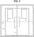
- an area may be laid out at a plurality of positions like areas A to C in Fig. 3 , or areas K to O in Fig. 4 .
- the radiographic apparatus 300 includes a plurality of column signal lines 106 and a plurality of drive lines 104.
- Each of the column signal lines 106 corresponds to different one of the columns in the radiation detection area.
- Each of the drive lines 104 corresponds to different one of the rows in the radiation detection area.
- the drive lines 104 are driven by a driving circuit 221.
- a first electrode of the first conversion element 102 and a first electrode of the second conversion element 122 are connected to a first main electrode of the first switch 103 and a first main electrode of the second switch 123, respectively.
- a second electrode of the first conversion element 102 and a second electrode of the second conversion element 122 are each connected to a bias line 108.
- Each of the bias lines 108 extends in the column direction and is connected to the second electrodes of a plurality of the conversion elements 102 and 122 arranged in a column direction in common.
- the bias lines 108 receive a bias voltage Vs from an element power supply circuit 226.
- the bias voltage Vs is supplied from the element power supply circuit 226.
- the power supply control unit 301 includes the battery and a direct-current-to-direct-current (DCDC) converter.
- the power supply control unit 301 includes the element power supply circuit 226, and generates an analog circuit power supply voltage and a digital circuit power supply voltage.
- the digital circuit power supply voltage is for use in driving control and communication.
- a second main electrode of the first switch 103 each in a plurality of the detection pixels 101 and a second main electrode of the second switch 123 each in a plurality of the correction pixels 121, in a single column, are connected to a column signal line 106.
- a control electrode of the first switch 103 each in the plurality of the detection pixels 101 and a control electrode of the second switch 123 each in the plurality of the correction pixels 121, in a single row, are connected to a drive line 104.
- the plurality of the column signal lines 106 is connected to a reading circuit 222.
- the reading circuit 222 includes a plurality of detection units 132, a multiplexer 134, and an analog-to-digital (AD) converter 136.
- the column signal lines 106 are each connected to corresponding one of the detection units 132 in the reading circuit 222.
- one column signal line 106 corresponds to one detection unit 132.
- the detection units 132 each include a differential amplifier, for example.
- the multiplexer 134 selects the detection units 132 in predetermined order and supplies a signal from the selected one of the detection units 132 to the AD converter 136.
- the AD converter 136 converts the supplied signal into a digital signal and outputs the digital signal.
- a signal processing unit 224 outputs information indicating irradiation of the radiographic apparatus 300 with radiation, based on the output of the reading circuit 222 (AD converter 136). Specifically, for example, the signal processing unit 224 performs characteristic correction processing, detects irradiation with radiation, and calculates a radiation dosage and a cumulative dosage.
- the characteristic correction processing includes removing dark current components and crosstalk components of the radiographic apparatus 300 by using the correction pixels 121.
- An imaging apparatus control unit 225 controls, for example, the driving circuit 221 and the reading circuit 222, based on information from the signal processing unit 224 and control commands from the control apparatus 310.
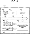
- Fig. 5 is a diagram illustrating the imaging apparatus control unit 225 of the radiographic apparatus 300.
- the imaging apparatus control unit 225 includes a driving control unit 400, a central processing unit (CPU) 401, a memory 402, a generation apparatus control unit 403, an image control unit 404, and a communication switching unit 405.
- the driving control unit 400 controls the driving circuit 221 and the reading circuit 222, based on information from the signal processing unit 224 and control commands from the control apparatus 310.
- the driving control unit 400 communicates with the radiographic apparatus 300 to receive a radiographic image and to control operation.
- the CPU 401 controls the entire radiographic apparatus 300 using programs and various types of data stored in the memory 402.
- the memory 402 stores programs and various types of data that the CPU 401 uses in executing processing, for example.
- the various types of data include various types of data obtained by the processing of the CPU 401 and radiographic images.
- the generation apparatus control unit 403 controls communication with the radiation generation apparatus 324, based on information from the signal processing unit 224 and information from the driving control unit 400.
- the generation apparatus control unit 403 and the radiation generation apparatus 324 exchange information about control of the radiation generation apparatus 324 (such as notifications to start and stop radiation irradiation, a radiation dosage, and a cumulative dosage).
- the generation apparatus control unit 403 In a case where a radiation dosage in a radiation detection area (measuring field) as a monitoring target of a radiation dosage reaches a reference threshold (target cumulative dosage), the generation apparatus control unit 403 notifies the radiation generation apparatus 324 of a stop notification among pieces of information about the control of the radiation generation apparatus 324.
- Examples of the measuring field include the areas A to C in Fig. 3 and the areas K to O in Fig. 4 .
- the detection pixels 101 included in the radiation detection area (measuring field) correspond to an example of a dose detection unit for detecting a dose reached to the dose detection unit during radiation irradiation.
- the generation apparatus control unit 403 detects radiation incident on the measuring field by using the detection pixels 101, and calculates a cumulative dosage that is a cumulative value of doses (reached doses) detected by the signal processing unit 224 during a predetermined period.
- the generation apparatus control unit 403 issues a stop notification at a timing of when a radiation dosage in a measuring field selected as a monitoring target reaches the reference threshold (hereinafter, this procedure is referred to as a reached dose monitoring function).
- this procedure is referred to as a reached dose monitoring function.
- the following three control methods can be employed, for example.
- the generation apparatus control unit 403 issues a stop notification at a timing of when a cumulative value of any one of the selected measuring fields reaches the target cumulative dosage.
- an average control method the generation apparatus control unit 403 issues a stop notification at a timing of when an average of cumulative values of a plurality of selected measuring fields reaches a value set as the target cumulative dosage.
- the generation apparatus control unit 403 issues a stop notification at a timing of when all cumulative values of a plurality of selected measuring fields reach a value set as the target cumulative dosage.
- Control methods other than the foregoing methods may be used. Two or more of the foregoing methods may be used in combination.
- the generation apparatus control unit 403 may specify a combination of operators like (R1 AND R2) OR (R2 AND R5) OR (R5 AND R4) OR (R4 AND R1), and issue a stop notification in response to two measuring fields reaching the target cumulative dosage first.
- OR, average, and control methods are described as examples, other control methods and operators (such as NAND, NOR, and XOR) may also be combined.
- the control method for AEC may be one using at least any one of the AND, OR, average, NAND, NOR, and XOR methods.
- the mode in which the generation apparatus control unit 403 issues a stop notification is set based on any one of the radiographic apparatus 300, the radiation generation apparatus 324, and the control apparatus 310, for example.
- the radiographic system 10 may have a mode in which radiation irradiation is not stopped in accordance with a reached radiation dosage.
- the radiographic system 10 may include a not-illustrated general exposure control sensor (such as an ion chamber and a photo timer) attached outside the radiographic apparatus 300 and stop radiation irradiation in accordance with a radiation dosage. While, in the present exemplary embodiment, the radiographic apparatus 300 includes the generation apparatus control unit 403, the radiographic apparatus 300 may be configured to detect radiation irradiation by using the signal processing unit 224 and perform radiographic imaging without communicating with the radiation generation apparatus 324.
- the image control unit 404 stores an image from the reading circuit 222 into the memory 402, and controls communication with the control apparatus 310.
- the image control unit 404 and the control apparatus 310 exchange radiographic images and control-related information (such as control commands).
- the communication switching unit 405 switches the wired communication unit 303 and the wireless communication unit 304 to enable communication by the wired communication unit 303 when the first communication cable 307 is connected to the radiographic apparatus 300, and enable communication by the wireless communication unit 304 when the first communication cable 307 is disconnected from the radiographic apparatus 300.
- Fig. 6 is a diagram illustrating the control apparatus 310. As illustrated in Fig. 6 , the control apparatus 310 includes a determination unit 501, a calculation unit 502, and a display control unit 503.
- the determination unit 501 determines an area (region of interest) to calculate a dose index value in a radiographic image generated by the radiographic apparatus 300.
- an area to calculate a dose index value is broadly classified into the following two types: a measuring field like the areas A to C in Fig. 3 and the areas K to O in Fig. 4 , and a predetermined area like an area P in Fig. 3 and an area Q in Fig. 4 . Examples of the latter area is an optional area which includes the entire area of the radiographic image, is specified by the operator 312, or corresponds to an imaging site. Such areas are exemplary and not restrictive.
- areas to calculate the dose index value are represented by rectangles as illustrated in Figs. 8B and 8C , for example.
- the areas may be represented by figures of any shape, such as a circular shape and a trapezoidal shape.
- Examples of a dose index value to be calculated in an area determined by the determination unit 501 include an EI value. While, in the present exemplary embodiment, an EI value is used as a dose index value, similar techniques can be applied to dose indices in general.
- a dose index value may be a value proportional or inversely proportional to a pixel value of a radiographic image.
- the calculation unit 502 calculates a dose index value of an area determined by the determination unit 501.
- a dose index target value for example, target exposure index EIt
- a deviation index for example, deviation index DI
- a deviation index DI is greater than 0, it is determined that the dose is higher than normal. If the deviation index DI is less than 0, it is determined that the dose is lower than normal.
- the dose index target value does not necessarily need to be set area by area.
- a first dose index target value may be set for the first and second areas in common, and a second dose index target value may be set for the third area.
- the display control unit 503 displays at least one of the indices calculated by the calculation unit 502, namely, the dose index values, dose index target values, and deviation indices, on the display apparatus 314.
- a method for displaying the at least one of the indices on the display apparatus 314 may be changed in accordance with an imaging condition.
- the determination unit 501, the calculation unit 502, and the display control unit 503 are described as functions of the control apparatus 310.
- the radiographic apparatus 300 may be configured to include the functions of the determination unit 501, the calculation unit 502, and the display control unit 503.
- the control apparatus 310 or the radiographic apparatus 300 may have functions corresponding to the determination unit 501, the calculation unit 502, and the display control unit 503.
- the determination unit 501 initially excludes an area that has not been irradiated with radiation and is outside the region of interest of a diagnostic image, from an EI value calculation area of a radiographic image.
- the exclusion method include a method for performing calculations based on collimator information or tube-to-flat panel detector (FPD) distance (FDD) information, a method for extracting an irradiated field from the image using various types of imaging site information determined in advance, and a method for performing determination using machine learning.
- the determination unit 501 identifies a direct radiation equivalent area and excludes an area outside the region of interest from the EI value calculation area.
- the exclusion method include an empirical fixed threshold method, a mode method, a differential histogram method, a percentile method, and discriminant analysis.
- step S703 the determination unit 501 excludes, from the EI value calculation area, a low dose area which is in the region of interest but is not to be used as a normal diagnostic image for calculation of a dose index of the region of interest.
- the exclusion method include region growing and snakes.
- the EI value calculation area is determined by applying the processing so far to the area determined to calculate a dose index value by the determination unit 501 in advance, or by applying the processing to the entire radiographic image and then extracting the area determined to calculate a dose index value by the determination unit 501.
- steps S701 to S703 may or may not be performed in a selective manner.
- the processing order is not limited to the foregoing procedure.
- the exclusion processing of step S703 may be performed before the exclusion processing of step S702.
- step S704 the calculation unit 502 calculates a representative value of the region of interest in the radiographic image determined by the processing of steps S701 to S703.
- a representative value include a pixel value of, for example, an average, a median, and a mode.
- a representative value of each of the regions of interest is calculated. The operator 312 can thus identify a dose value in each of the regions of interest.
- step S705 the calculation unit 502 converts the representative value into a dose, based on a known relationship between an incident dose and a pixel value.
- the operator 312 checks whether radiographic imaging with an expected radiation dose has been performed.
- the display control unit 503 displays the dose index values calculated by the calculation unit 502 on the display apparatus 314.
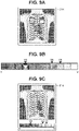
- the dose index values may be displayed as annotations at corners of a radiographic image. As illustrated in Fig. 8B , each of the dose index values may be superimposed on an image area where the corresponding dose index value has been calculated. Alternatively, the dose index values may be displayed separately from the radiographic image. For example, as illustrated in Fig. 8C , the dose index values may be displayed next to the radiographic image. As illustrated in Fig. 8D , the dose index values may be displayed without the radiographic image. Moreover, as illustrated in Fig. 9A , each of the dose index values may be rendered in a gray scale (or color scale) and displayed on the radiographic image. As illustrated in Fig.
- the radiographic image and the gray scale (or color scale) may be displayed in combination.
- at least two or more pieces of information about the values calculated by the calculation unit 502 may be displayed by changing at least either color or tone level.
- Figs. 8A to 8D and 9A to 9C illustrate examples of displaying the dose index values using text or color
- the display method may be defined by any combination of recognizable expressions, such as text, symbols, figures, sizes, color, and shapes.
- the display control unit 503 may display dose index target values and deviation index values along with the dose index values.
- the dose index target values and the deviation index values may be displayed by the same display method as that of the dose index values or by any other display method.
- a warning dialog may be displayed in a case where the dose index values and deviation index reach or exceed a predetermined threshold, for example. Only one such threshold may be set. Thresholds may be set for respective areas where the dose index values are calculated.
- the display control unit 503 may identifiably display, on the display apparatus 314, a measuring field that has been used for determination of stopping the radiation irradiation, among the one or more measuring fields.
- the control method is the AND method
- one or more measuring fields lastly reached the target dose are identifiably displayed.
- the control method is the OR method
- the measuring field first reached the threshold is identifiably displayed.
- the control method is the average method
- all the measuring fields are identifiably displayed. Examples of the method for identifiable display include identifiably displaying text information, and highlighting the measuring field(s) on the radiographic image.
- the dose index value(s) of the measuring field(s) ultimately used for determination of stopping the radiation irradiation may be displayed.
- the dose index values of all the measuring fields may be displayed, and the measuring field(s) ultimately used for determination of stopping the radiation irradiation may be marked up.
- the radiographic apparatus 300 When the radiographic system 10 is powered up and the radiographic apparatus 300 is powered on, the radiographic apparatus 300 performs initialization to enable communication with the control apparatus 310.
- the radiographic system 10 sets subject information, such as an identifier (ID), name, and date of birth of the subject 306, into the control apparatus 310.
- the radiographic system 10 also sets imaging information, such as an imaging site, a measuring field, and a dose index target value for the subject 306.
- the subject information and the imaging information may be automatically set by selecting a test order received via the in-hospital LAN 315.
- the operator 312 may set the imaging information by selecting a predetermined imaging protocol. Yet alternatively, the operator 312 may directly input and set the subject information and the imaging information.
- the radiographic system 10 sets the measuring field(s) of the radiographic apparatus 300, based on the input information.
- the operator 312 fixes the posture of the subject 306 and the radiographic apparatus 300.
- the operator 312 further inputs a dose, maximum irradiation time, a tube current, a tube voltage, site information, the measuring field(s), and the dose index target value(s) into the control apparatus 310.
- the control apparatus 310 transmits the input irradiation condition of radiation, site information, measuring field(s), and dose index target value(s) to the radiographic apparatus 300 and the radiation generation apparatus 324.
- the radiographic system 10 may be configured so that the information is input into the radiation generation apparatus 324 and notified to the control apparatus 310 and the radiographic apparatus 300.
- the control apparatus 310 may obtain information managed in association with at least either the subject information or the imaging information.
- information managed in association with the site information may include AEC measuring field selection information, the AEC method for a case where a plurality of measuring fields is selected (such as the AND method), and target cumulative dosage serving as the threshold to stop radiation irradiation.
- the control apparatus 310 can obtain information about the AEC control method associated with at least either the subject information or the imaging information.
- the information managed in association with the site information includes selection information for selecting a right measuring field and a left measuring field (areas K and L in Fig.
- the information managed in association with the site information includes selection information for selecting the center measuring field (area M in Fig. 4 ).
- the control apparatus 310 is described to obtain the information managed in associated with the input or notified site information in step S101.
- such information may be managed in association with subject information or imaging information different from the site information.
- the information may be managed in association with an imaging technique, an imaging orientation, an imaging direction, the presence or absence of a grid, or the type of radiographic apparatus.
- step S102 the operator 312 presses the irradiation switch 311.
- the radiation source 325 emits radiation toward the subject 306.
- the radiographic apparatus 300 communicates with the radiation generation apparatus 324 to control start of radiation irradiation.
- the radiation irradiating the subject 306 are transmitted through the subject 306 and incident on the radiographic apparatus 300.
- the radiographic apparatus 300 detects radiation incident on the measuring field(s) by using the detection pixels 101, and the signal processing unit 224 calculates a cumulative dosage that is a cumulative value of a dose (reached dose) detected in a predetermined period.
- the imaging apparatus control unit 225 calculates a reference threshold, based on cumulative dosage information from the signal processing unit 224 and the site information and imaging condition input by the operator 312, and determines radiation irradiation stop timing, based on a mode set by the generation apparatus control unit 403.
- the radiographic apparatus 300 notifies the radiation generation apparatus 324 to stop the radiation irradiation via the first communication cable 307, the communication control apparatus 323, and the third communication cable 327, based on the determined radiation irradiation stop timing.
- the radiation generation apparatus 324 stops the radiation irradiation based on the notified radiation irradiation stop timing. While the radiographic apparatus 300 issues the notification to stop the radiation irradiation as a result of detection of the radiation, this is not restrictive.
- the radiographic apparatus 300 may be configured to transmit the reached dose at predetermined time intervals as a result of detection, and the radiation generation apparatus 324 may calculate a cumulative value of the reached dose. After the radiation irradiation is stopped, the radiographic apparatus 300 converts the incident radiation into visible light and then detects the visible light as radiographic image signals by using the photoelectric conversion elements. The radiographic apparatus 300 reads the radiographic image signals by driving the photoelectric conversion elements, and converts the analog signals into digital signals through the AD converter 136 to obtain a radiographic image.
- step S103 the radiographic system 10 transfers the obtained radiographic image from the radiographic apparatus 300 to the control apparatus 310 via the first communication cable 307, the communication control apparatus 323, and the third communication cable 327.
- the control apparatus 310 applies image processing to the received digital radiographic image.
- the control apparatus 310 displays the image-processed radiographic image on the display apparatus 314.
- the control apparatus 310 thus functions also as an image processing apparatus and a display control apparatus.
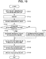
- step S104 the control apparatus 310 determines whether the reached dose monitoring function is enabled. In a case where the reached dose monitoring function is enabled (YES in step S104), the processing proceeds to step S105. On the other hand, in a case where the reached dose monitoring function is not enabled (NO in step S104), the processing proceeds to step S106.
- step S105 the determination unit 501 determines the measuring field(s) set in step S101 as a calculation area or areas (EI value calculation area(s)) to calculate radiation dosage.
- a calculation area or areas EI value calculation area(s)
- the calculation areas to calculate the radiation dosage are the measuring fields set to both lungs.
- the calculation area(s) determined by the determination unit 501 in step S105 does not necessarily need to be the same as the measuring field(s).
- a measuring field-based area obtained by the processing illustrated in Fig. 7 may be determined as a calculation area.
- the determination unit 501 determines a predetermined area as a calculation area to calculate radiation dosage.
- the predetermined area is set by the operator 312 in step S101.
- the operator 312 does not necessarily need to perform the setting.
- the radiographic system 10 may be configured so that the calculation area can be changed by the operator 312 after imaging.
- the calculation area(s) is/are determined based on whether the reached dose monitoring function is enabled, this is not restrictive.
- step S107 the control apparatus 310 transmits the received digital radiographic image to the calculation unit 502.
- the calculation unit 502 calculates the dose index value of each calculation area determined as described above based on the received radiographic image. For example, the calculation unit 502 calculates the dose index value of each of the measuring fields set to both lungs.
- step S108 the calculation unit 502 calculates the deviation index value(s). While, in the present exemplary embodiment, the control apparatus 310 calculates the dose index values and the deviation index values, these values may be calculated by the radiographic apparatus 300 or by another not-illustrated calculation apparatus.
- step S109 the control apparatus 310 transfers the dose index values and the deviation index values calculated by the calculation unit 502 to the display control unit 503.
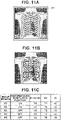
- the display control unit 503 provides display illustrated in Figs. 11A to 11C , for example.
- Figs. 11A to 11C illustrate an example where the reached dose monitoring function is enabled, the lung field is imaged while measuring fields at both lung areas R1 and R2 illustrated in Fig. 11B are set, and dose index values and deviation index values of the corresponding areas are displayed as illustrated Fig. 11A and 11C .
- Whether to display the calculated values on the display apparatus 314 may be set before imaging or set by the operator 312 after imaging.
- the display setting may be changed in accordance with the setting of the reached dose monitoring function.
- a not-illustrated icon or dialog may be controlled to be displayed in a case where the received dose index values and the received deviation index values satisfy a specific condition. Examples of the specific condition include that the dose index values and the deviation index values are greater than predetermined values.
- the measuring field(s) actually used by the reached dose monitoring function may be obtained from the radiographic apparatus 300 and reflected on the display content. For example, when radiation irradiation is stopped, displaying of which a measuring field or measuring fields are ultimately used for the determination of stopping the radiation irradiation can be performed on the display apparatus 314.
- the control apparatus 310 can explicitly display the one or more measuring fields used for the determination of stopping the radiation irradiation based on the control method. In a case where the control method is the AND method, the one or more measuring fields lastly reached the target dose can be explicitly displayed.
- the one or more measuring fields first reached the threshold can be explicitly displayed.
- the control method is the average method
- all the measuring fields can be explicitly displayed.
- the measuring field(s) may be explicitly displayed using text information.
- the measuring field(s) may be explicitly displayed at their positions on the radiographic image.
- the operator 312 can thus easily recognize which one or more of the measuring field(s) has been used for the determination of stopping the radiation irradiation.
- the operator 312 can also easily recognize which one or more of the measuring field(s) has been used for the determination of stopping the radiation irradiation and the dose index value(s) in the measuring field(s).
- the operator 312 can appropriately determine whether a desirable amount of radiation is incident on an AEC measuring field during radiographic imaging.
- the operator 312 can determine whether the regions of interest are irradiated with an appropriate amount of radiation by checking the respective dose index values and the deviation index values displayed on the display apparatus 314. For example, in a case where an imaging dose can be reduced by using the reached dose monitoring function and an appropriate amount of radiation is confirmed to be incident on each region of interest, it can be easily determined that the imaging has been appropriately conducted.
- a description will be provided of a configuration of a radiographic system 10 that calculates dose index values for a predetermined area and respective AEC measuring fields and displays the dose index values. This enables an operator to appropriately determine whether desirable amounts of radiation are incident on the predetermined area and the respective AEC measuring fields.
- Radiographic system 10 Processing by the radiographic system 10 according to the present exemplary embodiment will be described below with reference to Figs. 12A to 12D to Fig. 14 .
- a functional configuration of the radiographic system 10 is similar to the radiographic system 10 in the first exemplary embodiment, and the redundant description will thus be omitted.
- the display control unit 503 displays a first dose index value (in the diagrams, VI) and second dose index values (in the diagrams, V2 and V3) calculated by the calculation unit 502 on the display apparatus 314.
- the first dose index value and the second dose index values may be displayed as annotations at corners of the radiographic image.
- the first dose index value may be displayed at a given position on the radiation image, and the second dose index values may be superimposed at the respective positions of the measuring fields where the respective dose index values are calculated on the radiographic image.
- the dose index values may be displayed separately from the radiographic image.
- the dose index values may be displayed without the radiographic image.
- the dose index values may be rendered in a gray scale (or color scale) and displayed to express relative positions between the radiographic image and the measuring fields on the radiographic image.
- a gray scale or color scale
- the radiographic image and the gray scale may be displayed in combination. In other words, at least two or more pieces of information about the values calculated by the calculation unit 502 may be displayed by changing at least either color or tone level.
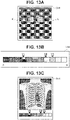
- Figs. 12A to 12D and 13A to 13C illustrate examples of displaying the dose index values using text or color
- the display method may be defined by any combination of recognizable expressions, such as text, symbols, figures, sizes, color, and shapes.
- the display control unit 503 may also display a first dose index target value, a first deviation index value, second dose index target values, and second deviation index values along with the first dose index value and the second dose index values.
- the first dose index target value and the first deviation index value may be displayed by a display method similar to or different from that of the first dose index value.
- the second dose index target values and the second deviation index values may be displayed by a display method similar to or different from that of the second dose index values.
- a warning dialog may be displayed in a case where a predetermined threshold is reached or exceeded, for example.
- the radiographic system 10 sets subject information, such as an identifier (ID), name, and date of birth of the subject 306 into the control apparatus 310.
- the radiographic system 10 also sets imaging information, such as an imaging site, the measuring field(s), and dose index target value(s) of the subject 306.
- the subject information and the imaging information may be automatically set by selecting a test order received via the in-hospital LAN 315.
- the operator 312 may set the imaging information by selecting a predetermined imaging protocol. Alternatively, the operator 312 may directly input and set the subject information and the imaging information.
- the radiographic system 10 sets the measuring field(s) of the radiographic apparatus 300 in accordance with the input information. After the information about the subject 306 and the information about the imaging site are set into the control apparatus 310, the operator 312 fixes the posture of the subject 306 and the radiographic apparatus 300.
- the operator 312 further inputs a dose, maximum irradiation time, a tube current, a tube voltage, site information, the measuring field(s), and the dose index target value(s) into the control apparatus 310.
- the control apparatus 310 transmits the input irradiation condition of radiation, site information, a measuring field(s), and a dose index target value(s) to the radiographic apparatus 300 and the radiation generation apparatus 324.
- the radiographic system 10 may be configured so that the information is input into the radiation generation apparatus 324 and notified to the control apparatus 310 and the radiographic apparatus 300.
- step S1402 the operator 312 presses the irradiation switch 311.
- the radiation source 325 emits radiation toward the subject 306.
- the radiographic apparatus 300 communicates with the radiation generation apparatus 324 to control start of radiation irradiation.
- the radiation irradiating the subject 306 are transmitted through the subject 306 and incident on the radiographic apparatus 300.
- the radiographic apparatus 300 detects radiation incident on the measuring field(s) by using the detection pixels 101, and the signal processing unit 224 calculates a cumulative dosage that is a cumulative value of a dose (reached dose) detected in a predetermined period.
- the imaging apparatus control unit 225 calculates a reference threshold based on cumulative dosage information from the signal processing unit 224 and the site information and imaging condition input by the operator 312, and determines radiation irradiation stop timing based on a mode set by the generation apparatus control unit 403.
- the radiographic apparatus 300 notifies the radiation generation apparatus 324 to stop the radiation irradiation via the first communication cable 307, the communication control apparatus 323, and the third communication cable 327 based on the determined radiation irradiation stop timing.
- the radiation generation apparatus 324 stops the radiation irradiation based on the notified radiation irradiation stop timing. While the radiographic apparatus 300 issues the notification to stop the radiation irradiation as a result of detection of the radiation, this is not restrictive.
- the radiographic apparatus 300 may be configured to transmit the reached dose at predetermined time intervals as a result of detection, and the radiation generation apparatus 324 may calculate a cumulative value of the reached dose. After the radiation irradiation is stopped, the radiographic apparatus 300 converts the incident radiation into visible light and then detects the visible light as radiographic image signals by using the photoelectric conversion elements. The radiographic apparatus 300 reads the radiographic image signals by driving the photoelectric conversion elements, and converts the analog signals into digital signals through the AD converter 136 to obtain a radiographic image.
- step S1403 the radiographic system 10 transfers the obtained radiographic image from the radiographic apparatus 300 to the control apparatus 310 via the first communication cable 307, the communication control apparatus 323, and the third communication cable 327.
- the control apparatus 310 applies image processing to the received digital radiographic image.
- the control apparatus 310 displays the image-processed radiographic image on the display apparatus 314.
- the control apparatus 310 thus functions also as an image processing apparatus and a display control apparatus.
- step S1404 the control apparatus 310 transfers the received digital radiographic image data (digital radiographic image) to the calculation unit 502.
- the calculation unit 502 calculates dose index values of a plurality of regions of interest, based on the received radiographic image data. More specifically, the calculation unit 502 calculates a first dose index value from a predetermined area of the radiographic image generated based on the received radiation image data. In the following description, the predetermined area refers to the entire radiographic image. However, this is not restrictive.
- the calculation unit 502 also calculates a second dose index value or values based on the measuring field(s) in the radiographic image generated based on the received radiographic image data.
- step S1405 the calculation unit 502 calculates deviation index values. While in the present exemplary embodiment the control apparatus 310 calculates the dose index values and the deviation index values, the dose index values and deviation index values may be calculated by the radiographic apparatus 300 or by another not-illustrated calculation apparatus.
- step S1406 the calculation unit 502 transfers the first dose index value, the second dose index value(s), the first dose index target value, the second dose index target value(s), the first deviation index value, and the second deviation index value(s) to the display control unit 503.
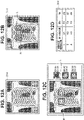
- the display control unit 503 provides display such as illustrated in Figs. 12A to 12D . In other words, the display control unit 503 displays information about the values calculated by the calculation unit 502 on the display apparatus 314.
- Figs. 12A to 12D illustrate examples of a case where the reached dose monitoring function is enabled, both lung areas K and L illustrated in Fig. 12B are set as measuring fields, and the lung field is imaged.
- Dose index values (first dose index value and second dose index values) and deviation index values (first deviation index value and second deviation index values) of the entire radiographic image and the areas of the respective measuring fields to be monitored are displayed as illustrated in Figs. 12A to 12C .
- Displaying the dose index values (first dose index value and second dose index values) and the deviation index values (first deviation index value and second deviation index values) of the entire radiographic image and the areas of the respective measuring fields to be monitored enables the operator 312 to check whether the doses to the region of interest of the radiographic image and the measuring fields set to be monitored are appropriate.
- Whether to display the calculated values on the display apparatus 314 may be set before imaging or set by the operator 312 after imaging.
- the display setting may be changed in accordance with the setting of the reached dose monitoring function.
- a not-illustrate icon or dialog may be controlled to be displayed in a case where the first dose index value and the second dose index value and the first deviation index value and the second deviation index value satisfy a specific condition. Examples of the specific condition include that any one of the first dose index value and the second dose index value and the first deviation index value and the second deviation index value is greater than a predetermined value.
- the calculation unit 502 may obtain the measuring field(s) used by the reached dose monitoring function from the radiographic apparatus 300 or the image control unit 404, and reflect the measuring field(s) on the display content.
- the operator 312 can appropriately determine whether desirable amounts of radiation are incident on the predetermined area and the respective AEC measuring fields by checking the first dose index value and the second dose index value displayed on the display apparatus 314. For example, in a case where the predetermined area is the entire area of the radiographic image, the operator 312 can check both the dose index value of the radiation irradiating the entire area and the dose index values of the radiation irradiating the measuring fields in a subsequent step.
- the operator 312 can easily determine that the imaging has been appropriately conducted.
- An exemplary embodiment of the present invention can also be implemented by processing for supplying a program for implementing one or more functions of the foregoing exemplary embodiments to a system or an apparatus via a network or a storage medium, and reading and executing the program by one or more processors in a computer of the system or apparatus. Circuits for implementing one or more of the functions may be used for implementation.
- the processors and circuits may include a CPU, a micro processing unit (MPU), a graphics processing unit (GPU), an application-specific integrated circuit (ASIC), and a field-programmable gate array (FPGA).
- the processors and circuits may also include a digital signal processor (DSP), a data flow processor (DFP), and a neural processing unit (NPU).
- DSP digital signal processor
- DFP data flow processor
- NPU neural processing unit
- the radiographic system according to each of the foregoing exemplary embodiments may be implemented as a single apparatus.
- a plurality of apparatuses may be communicably combined to execute the foregoing processing. Both cases are covered by the exemplary embodiments of the present invention.
- a common server apparatus or a group of servers may be configured to execute the foregoing processing.
- a plurality of apparatuses constituting the radiographic system may be capable of communication at a predetermined communication rate, and does not need to be located in the same facility or in the same country.
- An exemplary embodiment of the present invention may cover a mode in which a software program for implementing the functions of the foregoing exemplary embodiments is supplied to a system or an apparatus, and a computer of the system or apparatus reads and executes the supplied program code.
- the program code installed on the computer to implement the processing of the exemplary embodiment by the computer is therefore also an exemplary embodiment of the present invention.
- An operating system (OS) running on the computer may perform part or all of the actual processing based on instructions included in the program read by the computer, in which case the functions of the foregoing exemplary embodiments are implemented by the processing.
- OS operating system
- the present invention is not limited to the foregoing exemplary embodiments.
- Various modifications can be made, and such modifications are not excluded from the scope of the present invention. Examples of the modifications may include making the exemplary embodiments adaptable to capturing of moving images as well as still images.
- Embodiment(s) of the present invention can also be realized by a computer of a system or apparatus that reads out and executes computer executable instructions (e.g., one or more programs) recorded on a storage medium (which may also be referred to more fully as a 'non-transitory computer-readable storage medium') to perform the functions of one or more of the above-described embodiment(s) and/or that includes one or more circuits (e.g., application specific integrated circuit (ASIC)) for performing the functions of one or more of the above-described embodiment(s), and by a method performed by the computer of the system or apparatus by, for example, reading out and executing the computer executable instructions from the storage medium to perform the functions of one or more of the above-described embodiment(s) and/or controlling the one or more circuits to perform the functions of one or more of the above-described embodiment(s).
- computer executable instructions e.g., one or more programs
- a storage medium which may also be referred to more fully as
- the computer may comprise one or more processors (e.g., central processing unit (CPU), micro processing unit (MPU)) and may include a network of separate computers or separate processors to read out and execute the computer executable instructions.
- the computer executable instructions may be provided to the computer, for example, from a network or the storage medium.
- the storage medium may include, for example, one or more of a hard disk, a random-access memory (RAM), a read only memory (ROM), a storage of distributed computing systems, an optical disk (such as a compact disc (CD), digital versatile disc (DVD), or Blu-ray Disc (BD) TM ), a flash memory device, a memory card, and the like.
Landscapes
- Health & Medical Sciences (AREA)
- Life Sciences & Earth Sciences (AREA)
- Engineering & Computer Science (AREA)
- Medical Informatics (AREA)
- Heart & Thoracic Surgery (AREA)
- Molecular Biology (AREA)
- Biophysics (AREA)
- Nuclear Medicine, Radiotherapy & Molecular Imaging (AREA)
- Optics & Photonics (AREA)
- Pathology (AREA)
- Radiology & Medical Imaging (AREA)
- Biomedical Technology (AREA)
- Physics & Mathematics (AREA)
- High Energy & Nuclear Physics (AREA)
- Surgery (AREA)
- Animal Behavior & Ethology (AREA)
- General Health & Medical Sciences (AREA)
- Public Health (AREA)
- Veterinary Medicine (AREA)
- Human Computer Interaction (AREA)
- Multimedia (AREA)
- Signal Processing (AREA)
- Computer Vision & Pattern Recognition (AREA)
- Apparatus For Radiation Diagnosis (AREA)
Abstract
Description
- The present invention relates to a radiographic system, a radiographic method, and a program.
- As radiographic apparatuses for use in medical image diagnosis and nondestructive inspection using radiation, such as X-rays, radiographic apparatuses that include a matrix substrate including a pixel array formed by combining switches, like thin-film transistors (TFTs), with conversion elements, like photoelectric conversion elements, have been put to practical use.
- Several studies have been conducted to make radiographic apparatuses multifunctional. One of the approaches is to implement a built-in function for monitoring radiation irradiation. Such a function enables, for example, detection of a timing of starting radiation irradiation from a radiation source, detection of a timing of stopping the radiation irradiation, and detection of a radiation dosage or a cumulative dosage.
-
Japanese Patent No. 4217505 Japanese Patent No. 4217505 - There is a technique for calculating a dose index value by analyzing a captured radiographic image, to display the dose index value on a graphical user interface (GUI). The dose index value is a numerical representation of the radiation dose received by the radiographic image detection apparatus.
- An example of a dose index is an exposure index (EI). The dose index is a value for evaluating a dose used in radiographic imaging. EI is an index standardized by the International Electric Conference (IEC) as IEC 62494-1. Specifically, an area to calculate an EI value in a radiographic image is determined, and a representative value is extracted from among pixel values of pixels in the calculation area. A predetermined conversion is then performed on the extracted representative value, and the resulting dose index value is displayed. In each medical facility, EI information is managed and an EI value determined to be an optimum dose for radiographic images (for example, a minimum dose with satisfactory image quality) is set as a target value (Target Exposure Index) EIt. Determination of whether a dose is excessive or insufficient is then performed using a deviation (Deviation Index) DI between a calculated EI value and EIt to facilitate optimum imaging.
- According to a first aspect of the present invention, there is provided a radiographic system as specified in
claims 1 to 13. According to a second aspect of the present invention, there is provided a radiographic method as specified in claim 14. According to a third aspect of the present invention, there is provided a program as specified in claim 15. - Further features of the present invention will become apparent from the following description of exemplary embodiments with reference to the attached drawings.
-
-
Fig. 1 is a diagram illustrating an example of a radiographic system. -
Fig. 2 is a diagram illustrating an example of a radiographic apparatus. -
Fig. 3 is a diagram illustrating an example of a layout of measuring fields and an arbitrary area(s) (an entire area of a radiographic image, an area selected by an operator, an area corresponding to an imaging site, or the like). -
Fig. 4 is a diagram illustrating an example of a layout of measuring fields and an arbitrary area(s) (an entire area of a radiographic image, an area selected by an operator, an area corresponding to an imaging site, or the like). -
Fig. 5 is a diagram illustrating an example of an imaging apparatus control unit in the radiographic apparatus. -
Fig. 6 is a diagram illustrating an example of a control apparatus in the radiographic system. -
Fig. 7 illustrates an example of a flowchart for calculating an exposure index (EI) value. -
Figs. 8A to 8D are diagrams each illustrating a display example of dose index values. -
Figs. 9A to 9C are diagrams each illustrating a display example of the dose index values. -
Fig. 10 is a flowchart illustrating an operation example of the radiographic system. -
Figs. 11A to 11C are diagrams each illustrating a display example of dose index values. -
Figs. 12A to 12D are diagrams each illustrating a display example of dose index values. -
Figs. 13A to 13C are diagrams each illustrating a display example of the dose index values. -
Fig. 14 is a flowchart illustrating an operation example of a radiographic system. - For example, in a case where automatic exposure control (AEC) is used when lung fields are imaged, radiographic imaging is typically performed on measuring fields set at both lungs. In such a case, by stopping radiation irradiation at a timing of when an irradiation dose for both lungs reaches an optimum dose, an irradiation dose in the radiation irradiation can be reduced. Consequently, it is desirable that an exposure index (EI) value and a target value EIt are displayed or set based on the measuring fields.
- However, since conventional apparatuses display the EI value and set the target value EIt as a dose index of the entire radiographic image, whether a sufficient amount of radiation is incident on the AEC measuring fields is unable to be determined based on the numerical values.
- Exemplary embodiments of the present invention have been achieved in view of the foregoing issue, and are directed to providing a radiographic system where an operator can appropriately determine whether a desirable amount of radiation is incident on measuring fields during radiographic imaging using AEC.
- The present exemplary embodiments can also be directed to providing operations and effects that are derived from configurations described below and not obtainable by the conventional art.
- A radiographic system according to a first exemplary embodiment will be described below with reference to the drawings.
Fig. 1 is a diagram illustrating a radiographic system according to the present exemplary embodiment. - As illustrated in
Fig. 1 , aradiographic system 10 is disposed in aradiation chamber 1 where radiographic imaging using radiation irradiation is performed and acontrol chamber 2 in the vicinity of theradiation chamber 1. - The
radiation chamber 1 includes, as theradiographic system 10, aradiographic apparatus 300, anupright stand 302, afirst communication cable 307, an access point (AP) 320, acommunication control apparatus 323, aradiation generation apparatus 324, aradiation source 325, asecond communication cable 326, and athird communication cable 327. - The
control chamber 2 includes, as theradiographic system 10, acontrol apparatus 310, anirradiation switch 311, aninput apparatus 313, adisplay apparatus 314, an in-hospital local area network (LAN) 315, and afourth communication cable 316. - The configuration of the apparatuses installed in the
radiation chamber 1 and thecontrol chamber 2 is not limited to the foregoing. Any configuration that functions as theradiographic system 10 may be employed. - The
radiographic apparatus 300 includes a powersupply control unit 301 including a battery, awired communication unit 303, and awireless communication unit 304. Theradiographic apparatus 300 detects radiation transmitted through asubject 306 and generates a radiographic image. An image according to the present exemplary embodiment refers not only to an image being displayed on a display unit but also to an image being stored in a database or storage unit as image data. - The
wired communication unit 303 performs information exchange by cable connection using a communication standard of predetermined agreement or a standard, such as the Ethernet (registered trademark), for example. - The
wireless communication unit 304 includes a circuit substrate equipped with an antenna and a communication integrated circuit (IC), for example. The circuit substrate equipped with the communication IC performs communication processing using a wireless LAN-based protocol via the antenna. The frequency band, standard, and method of the wireless communication are not limited in particular. A proximity wireless communication method, such as near field communication (NFC) and Bluetooth®, or a method such as ultra-wideband (UWB) may be used. Thewireless communication unit 304 may support a plurality of wireless communication methods and perform communication by selecting one from among the supported wireless communication methods as appropriate. - The
upright stand 302 is a pedestal to which theradiographic apparatus 300 can be attached, to perform radiographic imaging in an upright position. Theradiographic apparatus 300 can be detachably attached to theupright stand 302, and can capture images both in an attached state and a detached state. - The
first communication cable 307 is a cable for connecting theradiographic apparatus 300 and thecommunication control apparatus 323. - The
AP 320 performs wireless communication with theradiographic apparatus 300. For example, theAP 320 is used to relay communication between theradiographic apparatus 300 and thecontrol apparatus 310 and between theradiographic apparatus 300 and theradiation generation apparatus 324 in using theradiographic apparatus 300 detached from theupright stand 302. - While
Fig. 1 illustrates a case where the communication is performed via theAP 320, either theradiographic apparatus 300 or thecommunication control apparatus 323 may serve as an AP to perform direct communication without the intermediary of theAP 320. - The
communication control apparatus 323 controls communication between theAP 320, theradiation generation apparatus 324, and thecontrol apparatus 310. - The
radiation generation apparatus 324 controls theradiation source 325 to emit radiation based on a predetermined irradiation condition. - The
radiation source 325 irradiates the subject 306 with radiation based on control by theradiation generation apparatus 324. - The
second communication cable 326 is a cable for connecting theAP 320 and thecommunication control apparatus 323. - The
third communication cable 327 is a cable for connecting theradiation generation apparatus 324 and thecommunication control apparatus 323. - The
control apparatus 310 communicates with theradiation generation apparatus 324 and theradiographic apparatus 300 via thecommunication control apparatus 323, and controls theradiographic system 10 in a centralized manner. - The
irradiation switch 311 inputs a radiation irradiation timing based on an operation by anoperator 312. - The
input apparatus 313 is an apparatus for inputting instructions from theoperator 312. Various input devices, such as a keyboard and a touch panel, are used as theinput apparatus 313. - The
display apparatus 314 is an apparatus for displaying an image-processed radiographic image and a graphical user interface (GUI). An example of thedisplay apparatus 314 is a display. - The in-
hospital LAN 315 is a backbone network in the hospital. - The
fourth communication cable 316 is a cable for connecting thecontrol apparatus 310 and thecommunication control apparatus 323 in theradiation chamber 1. -
Fig. 2 is a diagram illustrating theradiographic apparatus 300. As illustrated inFig. 2 , theradiographic apparatus 300 includes aradiation detector 100. Theradiation detector 100 has a function of detecting irradiating radiation. Theradiation detector 100 includes a plurality of pixels arranged to form a plurality of rows and a plurality of columns. In the following description, an area of theradiation detector 100 where the plurality of pixels is arranged will be referred to as a radiation detection area. The plurality of pixels includes imagingpixels 101 for obtaining a radiographic image or irradiation information, andcorrection pixels 121 for removing dark current components and crosstalk components. - In the present exemplary embodiment, the use of the
imaging pixels 101 for obtaining irradiation information will be described. Theimaging pixels 101 will therefore be hereinafter referred to asdetection pixels 101. Thedetection pixels 101 may be used for a purpose of obtaining radiographic images or for a purpose of obtaining irradiation information. Alternatively, thedetection pixels 101 may obtain both radiographic images and irradiation information. In other words, thedetection pixels 101 may be configured to obtain at least either radiographic images or irradiation information. - The
detection pixels 101 each include afirst conversion element 102 for converting radiation into an electrical signal, and afirst switch 103 disposed between acolumn signal line 106 and thefirst conversion element 102. - The
first conversion element 102 includes a scintillator, which is for converting radiation into light, and a photoelectric conversion element, which is for converting the light into an electrical signal. The scintillator is typically formed in a sheet shape to cover the radiation detection area, and shared by the plurality of pixels. Alternatively, thefirst conversion element 102 includes a conversion element that directly converts radiation into light. - The
first switch 103 includes a thin-film transistor (TFT) having an active region formed of a semiconductor, such as amorphous silicon and polycrystalline silicon (desirably polycrystalline silicon), for example. - The
correction pixels 121 each include asecond conversion element 122 for converting radiation into an electrical signal, and asecond switch 123 disposed between acolumn signal line 106 and thesecond conversion element 122. - Since the
second conversion element 122 and thesecond switch 123 are similar to thefirst conversion element 102 and thefirst switch 103, respectively, the redundant descriptions will be omitted. - An area where both
detection pixels 101 andcorrection pixels 121 for obtaining irradiation information are arranged is laid out at any position within the radiation detection area of theradiographic apparatus 300. For example, similar to a conventional separate AEC sensor, such an area may be laid out at a plurality of positions like areas A to C inFig. 3 , or areas K to O inFig. 4 . - The
radiographic apparatus 300 includes a plurality ofcolumn signal lines 106 and a plurality of drive lines 104. - Each of the
column signal lines 106 corresponds to different one of the columns in the radiation detection area. Each of the drive lines 104 corresponds to different one of the rows in the radiation detection area. - The drive lines 104 are driven by a driving
circuit 221. - A first electrode of the
first conversion element 102 and a first electrode of thesecond conversion element 122 are connected to a first main electrode of thefirst switch 103 and a first main electrode of thesecond switch 123, respectively. A second electrode of thefirst conversion element 102 and a second electrode of thesecond conversion element 122 are each connected to abias line 108. Each of the bias lines 108 extends in the column direction and is connected to the second electrodes of a plurality of theconversion elements - The bias lines 108 receive a bias voltage Vs from an element
power supply circuit 226. The bias voltage Vs is supplied from the elementpower supply circuit 226. - The power
supply control unit 301 includes the battery and a direct-current-to-direct-current (DCDC) converter. The powersupply control unit 301 includes the elementpower supply circuit 226, and generates an analog circuit power supply voltage and a digital circuit power supply voltage. The digital circuit power supply voltage is for use in driving control and communication. - A second main electrode of the
first switch 103 each in a plurality of thedetection pixels 101 and a second main electrode of thesecond switch 123 each in a plurality of thecorrection pixels 121, in a single column, are connected to acolumn signal line 106. A control electrode of thefirst switch 103 each in the plurality of thedetection pixels 101 and a control electrode of thesecond switch 123 each in the plurality of thecorrection pixels 121, in a single row, are connected to adrive line 104. The plurality of thecolumn signal lines 106 is connected to areading circuit 222. Here, thereading circuit 222 includes a plurality ofdetection units 132, amultiplexer 134, and an analog-to-digital (AD)converter 136. - The
column signal lines 106 are each connected to corresponding one of thedetection units 132 in thereading circuit 222. Here, onecolumn signal line 106 corresponds to onedetection unit 132. - The
detection units 132 each include a differential amplifier, for example. Themultiplexer 134 selects thedetection units 132 in predetermined order and supplies a signal from the selected one of thedetection units 132 to theAD converter 136. - The
AD converter 136 converts the supplied signal into a digital signal and outputs the digital signal. - A
signal processing unit 224 outputs information indicating irradiation of theradiographic apparatus 300 with radiation, based on the output of the reading circuit 222 (AD converter 136). Specifically, for example, thesignal processing unit 224 performs characteristic correction processing, detects irradiation with radiation, and calculates a radiation dosage and a cumulative dosage. The characteristic correction processing includes removing dark current components and crosstalk components of theradiographic apparatus 300 by using thecorrection pixels 121. - An imaging
apparatus control unit 225 controls, for example, the drivingcircuit 221 and thereading circuit 222, based on information from thesignal processing unit 224 and control commands from thecontrol apparatus 310. -
Fig. 5 is a diagram illustrating the imagingapparatus control unit 225 of theradiographic apparatus 300. As illustrated inFig. 5 , the imagingapparatus control unit 225 includes a drivingcontrol unit 400, a central processing unit (CPU) 401, amemory 402, a generationapparatus control unit 403, animage control unit 404, and acommunication switching unit 405. - The driving
control unit 400 controls the drivingcircuit 221 and thereading circuit 222, based on information from thesignal processing unit 224 and control commands from thecontrol apparatus 310. The drivingcontrol unit 400 communicates with theradiographic apparatus 300 to receive a radiographic image and to control operation. - The
CPU 401 controls the entireradiographic apparatus 300 using programs and various types of data stored in thememory 402. - The
memory 402 stores programs and various types of data that theCPU 401 uses in executing processing, for example. The various types of data include various types of data obtained by the processing of theCPU 401 and radiographic images. - The generation
apparatus control unit 403 controls communication with theradiation generation apparatus 324, based on information from thesignal processing unit 224 and information from the drivingcontrol unit 400. - The generation
apparatus control unit 403 and theradiation generation apparatus 324 exchange information about control of the radiation generation apparatus 324 (such as notifications to start and stop radiation irradiation, a radiation dosage, and a cumulative dosage). - In a case where a radiation dosage in a radiation detection area (measuring field) as a monitoring target of a radiation dosage reaches a reference threshold (target cumulative dosage), the generation
apparatus control unit 403 notifies theradiation generation apparatus 324 of a stop notification among pieces of information about the control of theradiation generation apparatus 324. Examples of the measuring field include the areas A to C inFig. 3 and the areas K to O inFig. 4 . Thedetection pixels 101 included in the radiation detection area (measuring field) correspond to an example of a dose detection unit for detecting a dose reached to the dose detection unit during radiation irradiation. The generationapparatus control unit 403 detects radiation incident on the measuring field by using thedetection pixels 101, and calculates a cumulative dosage that is a cumulative value of doses (reached doses) detected by thesignal processing unit 224 during a predetermined period. - The generation
apparatus control unit 403 issues a stop notification at a timing of when a radiation dosage in a measuring field selected as a monitoring target reaches the reference threshold (hereinafter, this procedure is referred to as a reached dose monitoring function). In a case where a plurality of measuring fields is selected as a monitoring target, the following three control methods can be employed, for example. In an OR control method, the generationapparatus control unit 403 issues a stop notification at a timing of when a cumulative value of any one of the selected measuring fields reaches the target cumulative dosage. In an average control method, the generationapparatus control unit 403 issues a stop notification at a timing of when an average of cumulative values of a plurality of selected measuring fields reaches a value set as the target cumulative dosage. In an AND control method, the generationapparatus control unit 403 issues a stop notification at a timing of when all cumulative values of a plurality of selected measuring fields reach a value set as the target cumulative dosage. Control methods other than the foregoing methods may be used. Two or more of the foregoing methods may be used in combination. - If, for example, four measuring fields R1, R2, R4, and R5 in
Figs. 11A to 11C are selected, it can be determined that irradiation of two juxtaposed measuring fields with as much radiation as the target cumulative dosage is sufficient since theradiographic apparatus 300 is used in more than one orientation. In such a case, the generationapparatus control unit 403 may specify a combination of operators like (R1 AND R2) OR (R2 AND R5) OR (R5 AND R4) OR (R4 AND R1), and issue a stop notification in response to two measuring fields reaching the target cumulative dosage first. While, the OR, average, and control methods are described as examples, other control methods and operators (such as NAND, NOR, and XOR) may also be combined. Specifically, the control method for AEC may be one using at least any one of the AND, OR, average, NAND, NOR, and XOR methods. - The mode in which the generation
apparatus control unit 403 issues a stop notification is set based on any one of theradiographic apparatus 300, theradiation generation apparatus 324, and thecontrol apparatus 310, for example. Theradiographic system 10 may have a mode in which radiation irradiation is not stopped in accordance with a reached radiation dosage. Theradiographic system 10 may include a not-illustrated general exposure control sensor (such as an ion chamber and a photo timer) attached outside theradiographic apparatus 300 and stop radiation irradiation in accordance with a radiation dosage. While, in the present exemplary embodiment, theradiographic apparatus 300 includes the generationapparatus control unit 403, theradiographic apparatus 300 may be configured to detect radiation irradiation by using thesignal processing unit 224 and perform radiographic imaging without communicating with theradiation generation apparatus 324. - The
image control unit 404 stores an image from thereading circuit 222 into thememory 402, and controls communication with thecontrol apparatus 310. Theimage control unit 404 and thecontrol apparatus 310 exchange radiographic images and control-related information (such as control commands). - The
communication switching unit 405 switches the wiredcommunication unit 303 and thewireless communication unit 304 to enable communication by the wiredcommunication unit 303 when thefirst communication cable 307 is connected to theradiographic apparatus 300, and enable communication by thewireless communication unit 304 when thefirst communication cable 307 is disconnected from theradiographic apparatus 300. -
Fig. 6 is a diagram illustrating thecontrol apparatus 310. As illustrated inFig. 6 , thecontrol apparatus 310 includes adetermination unit 501, acalculation unit 502, and adisplay control unit 503. - The
determination unit 501 determines an area (region of interest) to calculate a dose index value in a radiographic image generated by theradiographic apparatus 300. As employed herein, an area to calculate a dose index value is broadly classified into the following two types: a measuring field like the areas A to C inFig. 3 and the areas K to O inFig. 4 , and a predetermined area like an area P inFig. 3 and an area Q inFig. 4 . Examples of the latter area is an optional area which includes the entire area of the radiographic image, is specified by theoperator 312, or corresponds to an imaging site. Such areas are exemplary and not restrictive. - In the present exemplary embodiment, areas to calculate the dose index value are represented by rectangles as illustrated in
Figs. 8B and 8C , for example. However, this is not restrictive. The areas may be represented by figures of any shape, such as a circular shape and a trapezoidal shape. - Examples of a dose index value to be calculated in an area determined by the
determination unit 501 include an EI value. While, in the present exemplary embodiment, an EI value is used as a dose index value, similar techniques can be applied to dose indices in general. A dose index value may be a value proportional or inversely proportional to a pixel value of a radiographic image. - The
calculation unit 502 calculates a dose index value of an area determined by thedetermination unit 501. A dose index target value (for example, target exposure index EIt) which is used to determine that an optimum dose is applied may be set area by area, and thecalculation unit 502 may calculate a deviation index (for example, deviation index DI). The target exposure index EIt and the deviation index DI are indices standardized as International Electric Conference (IEC) 62494-1. Specifically, the deviation index DI is calculated by the following equation:
- In general, if a deviation index DI is greater than 0, it is determined that the dose is higher than normal. If the deviation index DI is less than 0, it is determined that the dose is lower than normal.
- The dose index target value does not necessarily need to be set area by area. For example, in a case where dose index target values are set for a first area, a second area, and a third area, a first dose index target value may be set for the first and second areas in common, and a second dose index target value may be set for the third area.
- The
display control unit 503 displays at least one of the indices calculated by thecalculation unit 502, namely, the dose index values, dose index target values, and deviation indices, on thedisplay apparatus 314. A method for displaying the at least one of the indices on thedisplay apparatus 314 may be changed in accordance with an imaging condition. - In the present exemplary embodiment, the
determination unit 501, thecalculation unit 502, and thedisplay control unit 503 are described as functions of thecontrol apparatus 310. However, theradiographic apparatus 300 may be configured to include the functions of thedetermination unit 501, thecalculation unit 502, and thedisplay control unit 503. In other words, at least either thecontrol apparatus 310 or theradiographic apparatus 300 may have functions corresponding to thedetermination unit 501, thecalculation unit 502, and thedisplay control unit 503. - A procedure for calculating an EI value from a radiographic image will be described with reference to a flowchart of
Fig. 7 . - In step S701, the
determination unit 501 initially excludes an area that has not been irradiated with radiation and is outside the region of interest of a diagnostic image, from an EI value calculation area of a radiographic image. Examples of the exclusion method include a method for performing calculations based on collimator information or tube-to-flat panel detector (FPD) distance (FDD) information, a method for extracting an irradiated field from the image using various types of imaging site information determined in advance, and a method for performing determination using machine learning. - In step S702, the
determination unit 501 identifies a direct radiation equivalent area and excludes an area outside the region of interest from the EI value calculation area. Examples of the exclusion method include an empirical fixed threshold method, a mode method, a differential histogram method, a percentile method, and discriminant analysis. - In step S703, the
determination unit 501 excludes, from the EI value calculation area, a low dose area which is in the region of interest but is not to be used as a normal diagnostic image for calculation of a dose index of the region of interest. Examples of the exclusion method include region growing and snakes. - The EI value calculation area is determined by applying the processing so far to the area determined to calculate a dose index value by the
determination unit 501 in advance, or by applying the processing to the entire radiographic image and then extracting the area determined to calculate a dose index value by thedetermination unit 501. - The foregoing processing of steps S701 to S703 may or may not be performed in a selective manner. The processing order is not limited to the foregoing procedure. For example, the exclusion processing of step S703 may be performed before the exclusion processing of step S702.
- In step S704, the
calculation unit 502 calculates a representative value of the region of interest in the radiographic image determined by the processing of steps S701 to S703. Examples of a representative value include a pixel value of, for example, an average, a median, and a mode. In a case where there is a plurality of regions of interest like when a plurality of measuring fields is set, a representative value of each of the regions of interest is calculated. Theoperator 312 can thus identify a dose value in each of the regions of interest. - In step S705, the
calculation unit 502 converts the representative value into a dose, based on a known relationship between an incident dose and a pixel value. Thecalculation unit 502 then calculates a dose index value by multiplying the converted dose by a constant. More specifically, thecalculation unit 502 calculates the dose index value (EI value) by converting the representative value in such a manner that 100 = 1 µGy. At the same time, thecalculation unit 502 calculates a deviation index DI from the dose index target value EIt. Theoperator 312 checks whether radiographic imaging with an expected radiation dose has been performed. - Next, display examples of dose index values on the
display apparatus 314 will be described with reference toFigs. 8A to 8D andFigs. 9A to 9C . - The
display control unit 503 displays the dose index values calculated by thecalculation unit 502 on thedisplay apparatus 314. - As illustrated in
Fig. 8A , the dose index values may be displayed as annotations at corners of a radiographic image. As illustrated inFig. 8B , each of the dose index values may be superimposed on an image area where the corresponding dose index value has been calculated. Alternatively, the dose index values may be displayed separately from the radiographic image. For example, as illustrated inFig. 8C , the dose index values may be displayed next to the radiographic image. As illustrated inFig. 8D , the dose index values may be displayed without the radiographic image. Moreover, as illustrated inFig. 9A , each of the dose index values may be rendered in a gray scale (or color scale) and displayed on the radiographic image. As illustrated inFig. 9B , only the gray scale (or color scale) may be separately displayed. As illustrated inFig. 9C , the radiographic image and the gray scale (or color scale) may be displayed in combination. In other words, at least two or more pieces of information about the values calculated by thecalculation unit 502 may be displayed by changing at least either color or tone level. - While
Figs. 8A to 8D and9A to 9C illustrate examples of displaying the dose index values using text or color, the display method may be defined by any combination of recognizable expressions, such as text, symbols, figures, sizes, color, and shapes. Moreover, thedisplay control unit 503 may display dose index target values and deviation index values along with the dose index values. The dose index target values and the deviation index values may be displayed by the same display method as that of the dose index values or by any other display method. Instead of displaying the dose index values or deviation index values, a warning dialog may be displayed in a case where the dose index values and deviation index reach or exceed a predetermined threshold, for example. Only one such threshold may be set. Thresholds may be set for respective areas where the dose index values are calculated. - In a case where a notification to stop the radiation irradiation is performed, the
display control unit 503 may identifiably display, on thedisplay apparatus 314, a measuring field that has been used for determination of stopping the radiation irradiation, among the one or more measuring fields. In a case where the control method is the AND method, one or more measuring fields lastly reached the target dose are identifiably displayed. In a case where the control method is the OR method, the measuring field first reached the threshold is identifiably displayed. In a case where the control method is the average method, all the measuring fields are identifiably displayed. Examples of the method for identifiable display include identifiably displaying text information, and highlighting the measuring field(s) on the radiographic image. The dose index value(s) of the measuring field(s) ultimately used for determination of stopping the radiation irradiation may be displayed. The dose index values of all the measuring fields may be displayed, and the measuring field(s) ultimately used for determination of stopping the radiation irradiation may be marked up. - Next, an operation of the
radiographic system 10 during imaging will be described with reference toFig. 10 . - When the
radiographic system 10 is powered up and theradiographic apparatus 300 is powered on, theradiographic apparatus 300 performs initialization to enable communication with thecontrol apparatus 310. - In step S101, the
radiographic system 10 sets subject information, such as an identifier (ID), name, and date of birth of the subject 306, into thecontrol apparatus 310. Theradiographic system 10 also sets imaging information, such as an imaging site, a measuring field, and a dose index target value for the subject 306. For example, the subject information and the imaging information may be automatically set by selecting a test order received via the in-hospital LAN 315. Theoperator 312 may set the imaging information by selecting a predetermined imaging protocol. Yet alternatively, theoperator 312 may directly input and set the subject information and the imaging information. Theradiographic system 10 sets the measuring field(s) of theradiographic apparatus 300, based on the input information. After the information about the subject 306 and the information about the imaging site are set into thecontrol apparatus 310, theoperator 312 fixes the posture of the subject 306 and theradiographic apparatus 300. Theoperator 312 further inputs a dose, maximum irradiation time, a tube current, a tube voltage, site information, the measuring field(s), and the dose index target value(s) into thecontrol apparatus 310. Thecontrol apparatus 310 transmits the input irradiation condition of radiation, site information, measuring field(s), and dose index target value(s) to theradiographic apparatus 300 and theradiation generation apparatus 324. Theradiographic system 10 may be configured so that the information is input into theradiation generation apparatus 324 and notified to thecontrol apparatus 310 and theradiographic apparatus 300. Here, thecontrol apparatus 310 may obtain information managed in association with at least either the subject information or the imaging information. For example, information managed in association with the site information may include AEC measuring field selection information, the AEC method for a case where a plurality of measuring fields is selected (such as the AND method), and target cumulative dosage serving as the threshold to stop radiation irradiation. In other words, thecontrol apparatus 310 can obtain information about the AEC control method associated with at least either the subject information or the imaging information. Specifically, for example, in a case where the site information indicates a front chest, the information managed in association with the site information includes selection information for selecting a right measuring field and a left measuring field (areas K and L inFig. 4 ) corresponding to both lung fields and the AND method that is an AEC method. In a case where the site information indicates a side chest, the information managed in association with the site information includes selection information for selecting the center measuring field (area M inFig. 4 ). In the present exemplary embodiment, thecontrol apparatus 310 is described to obtain the information managed in associated with the input or notified site information in step S101. However, such information may be managed in association with subject information or imaging information different from the site information. For example, the information may be managed in association with an imaging technique, an imaging orientation, an imaging direction, the presence or absence of a grid, or the type of radiographic apparatus. - After the completion of the imaging preparations, in step S102, the
operator 312 presses theirradiation switch 311. In response to theirradiation switch 311 being pressed, theradiation source 325 emits radiation toward the subject 306. Here, theradiographic apparatus 300 communicates with theradiation generation apparatus 324 to control start of radiation irradiation. The radiation irradiating the subject 306 are transmitted through the subject 306 and incident on theradiographic apparatus 300. In a case where theradiographic apparatus 300 is set to use the reached dose monitoring function, theradiographic apparatus 300 detects radiation incident on the measuring field(s) by using thedetection pixels 101, and thesignal processing unit 224 calculates a cumulative dosage that is a cumulative value of a dose (reached dose) detected in a predetermined period. The imagingapparatus control unit 225 calculates a reference threshold, based on cumulative dosage information from thesignal processing unit 224 and the site information and imaging condition input by theoperator 312, and determines radiation irradiation stop timing, based on a mode set by the generationapparatus control unit 403. Theradiographic apparatus 300 notifies theradiation generation apparatus 324 to stop the radiation irradiation via thefirst communication cable 307, thecommunication control apparatus 323, and thethird communication cable 327, based on the determined radiation irradiation stop timing. Theradiation generation apparatus 324 stops the radiation irradiation based on the notified radiation irradiation stop timing. While theradiographic apparatus 300 issues the notification to stop the radiation irradiation as a result of detection of the radiation, this is not restrictive. Theradiographic apparatus 300 may be configured to transmit the reached dose at predetermined time intervals as a result of detection, and theradiation generation apparatus 324 may calculate a cumulative value of the reached dose. After the radiation irradiation is stopped, theradiographic apparatus 300 converts the incident radiation into visible light and then detects the visible light as radiographic image signals by using the photoelectric conversion elements. Theradiographic apparatus 300 reads the radiographic image signals by driving the photoelectric conversion elements, and converts the analog signals into digital signals through theAD converter 136 to obtain a radiographic image. - In step S103, the
radiographic system 10 transfers the obtained radiographic image from theradiographic apparatus 300 to thecontrol apparatus 310 via thefirst communication cable 307, thecommunication control apparatus 323, and thethird communication cable 327. Thecontrol apparatus 310 applies image processing to the received digital radiographic image. Thecontrol apparatus 310 displays the image-processed radiographic image on thedisplay apparatus 314. Thecontrol apparatus 310 thus functions also as an image processing apparatus and a display control apparatus. - In step S104, the
control apparatus 310 determines whether the reached dose monitoring function is enabled. In a case where the reached dose monitoring function is enabled (YES in step S104), the processing proceeds to step S105. On the other hand, in a case where the reached dose monitoring function is not enabled (NO in step S104), the processing proceeds to step S106. - In step S105, the
determination unit 501 determines the measuring field(s) set in step S101 as a calculation area or areas (EI value calculation area(s)) to calculate radiation dosage. For example, in the case of imaging the lung field, radiographic imaging is often performed on measuring fields set to both lungs. In such a case, the calculation areas to calculate the radiation dosage are the measuring fields set to both lungs. The calculation area(s) determined by thedetermination unit 501 in step S105 does not necessarily need to be the same as the measuring field(s). For example, a measuring field-based area obtained by the processing illustrated inFig. 7 may be determined as a calculation area. - In step S106, the
determination unit 501 determines a predetermined area as a calculation area to calculate radiation dosage. For example, the predetermined area is set by theoperator 312 in step S101. In a case where an area that can be determined regardless of the imaging information or the setting by theoperator 312, like the entire area of the radiographic image, is set as the predetermined area, theoperator 312 does not necessarily need to perform the setting. Theradiographic system 10 may be configured so that the calculation area can be changed by theoperator 312 after imaging. - While, in the present exemplary embodiment, the calculation area(s) is/are determined based on whether the reached dose monitoring function is enabled, this is not restrictive.
- In step S107, the
control apparatus 310 transmits the received digital radiographic image to thecalculation unit 502. Thecalculation unit 502 calculates the dose index value of each calculation area determined as described above based on the received radiographic image. For example, thecalculation unit 502 calculates the dose index value of each of the measuring fields set to both lungs. - In step S108, the
calculation unit 502 calculates the deviation index value(s). While, in the present exemplary embodiment, thecontrol apparatus 310 calculates the dose index values and the deviation index values, these values may be calculated by theradiographic apparatus 300 or by another not-illustrated calculation apparatus. - In step S109, the
control apparatus 310 transfers the dose index values and the deviation index values calculated by thecalculation unit 502 to thedisplay control unit 503. Thedisplay control unit 503 provides display illustrated inFigs. 11A to 11C , for example.Figs. 11A to 11C illustrate an example where the reached dose monitoring function is enabled, the lung field is imaged while measuring fields at both lung areas R1 and R2 illustrated inFig. 11B are set, and dose index values and deviation index values of the corresponding areas are displayed as illustratedFig. 11A and 11C . - Whether to display the calculated values on the
display apparatus 314 may be set before imaging or set by theoperator 312 after imaging. The display setting may be changed in accordance with the setting of the reached dose monitoring function. Alternatively, a not-illustrated icon or dialog may be controlled to be displayed in a case where the received dose index values and the received deviation index values satisfy a specific condition. Examples of the specific condition include that the dose index values and the deviation index values are greater than predetermined values. - While, in the present exemplary embodiment, an image just captured is taken as an example, images captured in the past may be displayed in a similar manner. The measuring field(s) actually used by the reached dose monitoring function may be obtained from the
radiographic apparatus 300 and reflected on the display content. For example, when radiation irradiation is stopped, displaying of which a measuring field or measuring fields are ultimately used for the determination of stopping the radiation irradiation can be performed on thedisplay apparatus 314. In other words, thecontrol apparatus 310 can explicitly display the one or more measuring fields used for the determination of stopping the radiation irradiation based on the control method. In a case where the control method is the AND method, the one or more measuring fields lastly reached the target dose can be explicitly displayed. In a case where the control method is the OR method, the one or more measuring fields first reached the threshold can be explicitly displayed. In a case where the control method is the average method, all the measuring fields can be explicitly displayed. The measuring field(s) may be explicitly displayed using text information. The measuring field(s) may be explicitly displayed at their positions on the radiographic image. Theoperator 312 can thus easily recognize which one or more of the measuring field(s) has been used for the determination of stopping the radiation irradiation. Theoperator 312 can also easily recognize which one or more of the measuring field(s) has been used for the determination of stopping the radiation irradiation and the dose index value(s) in the measuring field(s). - In the above-described manner, a series of processes by the
radiographic system 10 is performed. - As a result of the foregoing, the
operator 312 can appropriately determine whether a desirable amount of radiation is incident on an AEC measuring field during radiographic imaging. - In a case of imaging in which a plurality of regions of interest is set, like when a plurality of measuring fields is set, the
operator 312 can determine whether the regions of interest are irradiated with an appropriate amount of radiation by checking the respective dose index values and the deviation index values displayed on thedisplay apparatus 314. For example, in a case where an imaging dose can be reduced by using the reached dose monitoring function and an appropriate amount of radiation is confirmed to be incident on each region of interest, it can be easily determined that the imaging has been appropriately conducted. - In a second exemplary embodiment, a description will be provided of a configuration of a
radiographic system 10 that calculates dose index values for a predetermined area and respective AEC measuring fields and displays the dose index values. This enables an operator to appropriately determine whether desirable amounts of radiation are incident on the predetermined area and the respective AEC measuring fields. - Processing by the
radiographic system 10 according to the present exemplary embodiment will be described below with reference toFigs. 12A to 12D toFig. 14 . A functional configuration of theradiographic system 10 is similar to theradiographic system 10 in the first exemplary embodiment, and the redundant description will thus be omitted. - Display examples of dose index values on the
display apparatus 314 will initially be described with reference toFigs. 12A to 12D and13A to 13C . - The
display control unit 503 displays a first dose index value (in the diagrams, VI) and second dose index values (in the diagrams, V2 and V3) calculated by thecalculation unit 502 on thedisplay apparatus 314. As illustrated inFig. 12A , the first dose index value and the second dose index values may be displayed as annotations at corners of the radiographic image. As illustrated inFig. 12B , the first dose index value may be displayed at a given position on the radiation image, and the second dose index values may be superimposed at the respective positions of the measuring fields where the respective dose index values are calculated on the radiographic image. As illustrated inFig. 12C , the dose index values may be displayed separately from the radiographic image. As illustrated inFig. 12D , the dose index values may be displayed without the radiographic image. Alternatively, as illustrated inFig. 13A , the dose index values may be rendered in a gray scale (or color scale) and displayed to express relative positions between the radiographic image and the measuring fields on the radiographic image. As illustrated inFig. 13B , only the gray scale (or color scale) may be separately displayed. As illustrated inFig. 13C , the radiographic image and the gray scale (or color scale) may be displayed in combination. In other words, at least two or more pieces of information about the values calculated by thecalculation unit 502 may be displayed by changing at least either color or tone level. - While
Figs. 12A to 12D and13A to 13C illustrate examples of displaying the dose index values using text or color, the display method may be defined by any combination of recognizable expressions, such as text, symbols, figures, sizes, color, and shapes. Moreover, thedisplay control unit 503 may also display a first dose index target value, a first deviation index value, second dose index target values, and second deviation index values along with the first dose index value and the second dose index values. The first dose index target value and the first deviation index value may be displayed by a display method similar to or different from that of the first dose index value. The second dose index target values and the second deviation index values may be displayed by a display method similar to or different from that of the second dose index values. Instead of displaying the first dose index target value, the first deviation index value, the second dose index target values, and the second deviation index values, a warning dialog may be displayed in a case where a predetermined threshold is reached or exceeded, for example. - Next, an operation of the
radiographic system 10 during imaging according to the second exemplary embodiment will be described with reference toFig. 14 . - In step S1401, the
radiographic system 10 sets subject information, such as an identifier (ID), name, and date of birth of the subject 306 into thecontrol apparatus 310. Theradiographic system 10 also sets imaging information, such as an imaging site, the measuring field(s), and dose index target value(s) of the subject 306. - For example, the subject information and the imaging information may be automatically set by selecting a test order received via the in-
hospital LAN 315. Theoperator 312 may set the imaging information by selecting a predetermined imaging protocol. Alternatively, theoperator 312 may directly input and set the subject information and the imaging information. Theradiographic system 10 sets the measuring field(s) of theradiographic apparatus 300 in accordance with the input information. After the information about the subject 306 and the information about the imaging site are set into thecontrol apparatus 310, theoperator 312 fixes the posture of the subject 306 and theradiographic apparatus 300. Theoperator 312 further inputs a dose, maximum irradiation time, a tube current, a tube voltage, site information, the measuring field(s), and the dose index target value(s) into thecontrol apparatus 310. Thecontrol apparatus 310 transmits the input irradiation condition of radiation, site information, a measuring field(s), and a dose index target value(s) to theradiographic apparatus 300 and theradiation generation apparatus 324. Theradiographic system 10 may be configured so that the information is input into theradiation generation apparatus 324 and notified to thecontrol apparatus 310 and theradiographic apparatus 300. - After the completion of the imaging preparations, in step S1402, the
operator 312 presses theirradiation switch 311. In response to theirradiation switch 311 being pressed, theradiation source 325 emits radiation toward the subject 306. Here, theradiographic apparatus 300 communicates with theradiation generation apparatus 324 to control start of radiation irradiation. The radiation irradiating the subject 306 are transmitted through the subject 306 and incident on theradiographic apparatus 300. In a case where theradiographic apparatus 300 is set to use the reached dose monitoring function, theradiographic apparatus 300 detects radiation incident on the measuring field(s) by using thedetection pixels 101, and thesignal processing unit 224 calculates a cumulative dosage that is a cumulative value of a dose (reached dose) detected in a predetermined period. The imagingapparatus control unit 225 calculates a reference threshold based on cumulative dosage information from thesignal processing unit 224 and the site information and imaging condition input by theoperator 312, and determines radiation irradiation stop timing based on a mode set by the generationapparatus control unit 403. Theradiographic apparatus 300 notifies theradiation generation apparatus 324 to stop the radiation irradiation via thefirst communication cable 307, thecommunication control apparatus 323, and thethird communication cable 327 based on the determined radiation irradiation stop timing. Theradiation generation apparatus 324 stops the radiation irradiation based on the notified radiation irradiation stop timing. While theradiographic apparatus 300 issues the notification to stop the radiation irradiation as a result of detection of the radiation, this is not restrictive. Theradiographic apparatus 300 may be configured to transmit the reached dose at predetermined time intervals as a result of detection, and theradiation generation apparatus 324 may calculate a cumulative value of the reached dose. After the radiation irradiation is stopped, theradiographic apparatus 300 converts the incident radiation into visible light and then detects the visible light as radiographic image signals by using the photoelectric conversion elements. Theradiographic apparatus 300 reads the radiographic image signals by driving the photoelectric conversion elements, and converts the analog signals into digital signals through theAD converter 136 to obtain a radiographic image. - In step S1403, the
radiographic system 10 transfers the obtained radiographic image from theradiographic apparatus 300 to thecontrol apparatus 310 via thefirst communication cable 307, thecommunication control apparatus 323, and thethird communication cable 327. Thecontrol apparatus 310 applies image processing to the received digital radiographic image. Thecontrol apparatus 310 displays the image-processed radiographic image on thedisplay apparatus 314. Thecontrol apparatus 310 thus functions also as an image processing apparatus and a display control apparatus. - In step S1404, the
control apparatus 310 transfers the received digital radiographic image data (digital radiographic image) to thecalculation unit 502. Thecalculation unit 502 calculates dose index values of a plurality of regions of interest, based on the received radiographic image data. More specifically, thecalculation unit 502 calculates a first dose index value from a predetermined area of the radiographic image generated based on the received radiation image data. In the following description, the predetermined area refers to the entire radiographic image. However, this is not restrictive. Thecalculation unit 502 also calculates a second dose index value or values based on the measuring field(s) in the radiographic image generated based on the received radiographic image data. - In step S1405, the
calculation unit 502 calculates deviation index values. While in the present exemplary embodiment thecontrol apparatus 310 calculates the dose index values and the deviation index values, the dose index values and deviation index values may be calculated by theradiographic apparatus 300 or by another not-illustrated calculation apparatus. - In step S1406, the
calculation unit 502 transfers the first dose index value, the second dose index value(s), the first dose index target value, the second dose index target value(s), the first deviation index value, and the second deviation index value(s) to thedisplay control unit 503. Thedisplay control unit 503 provides display such as illustrated inFigs. 12A to 12D . In other words, thedisplay control unit 503 displays information about the values calculated by thecalculation unit 502 on thedisplay apparatus 314. -
Figs. 12A to 12D illustrate examples of a case where the reached dose monitoring function is enabled, both lung areas K and L illustrated inFig. 12B are set as measuring fields, and the lung field is imaged. Dose index values (first dose index value and second dose index values) and deviation index values (first deviation index value and second deviation index values) of the entire radiographic image and the areas of the respective measuring fields to be monitored are displayed as illustrated inFigs. 12A to 12C . - Displaying the dose index values (first dose index value and second dose index values) and the deviation index values (first deviation index value and second deviation index values) of the entire radiographic image and the areas of the respective measuring fields to be monitored enables the
operator 312 to check whether the doses to the region of interest of the radiographic image and the measuring fields set to be monitored are appropriate. Whether to display the calculated values on thedisplay apparatus 314 may be set before imaging or set by theoperator 312 after imaging. The display setting may be changed in accordance with the setting of the reached dose monitoring function. Alternatively, a not-illustrate icon or dialog may be controlled to be displayed in a case where the first dose index value and the second dose index value and the first deviation index value and the second deviation index value satisfy a specific condition. Examples of the specific condition include that any one of the first dose index value and the second dose index value and the first deviation index value and the second deviation index value is greater than a predetermined value. - While, in the present exemplary embodiment, an image just captured is taken as an example, images captured in the past may be displayed in a similar manner. To calculate the second dose index value(s), the
calculation unit 502 may obtain the measuring field(s) used by the reached dose monitoring function from theradiographic apparatus 300 or theimage control unit 404, and reflect the measuring field(s) on the display content. - In such a manner, a series of processes by the
radiographic system 10 according to the second exemplary embodiment is performed. - As a result of the foregoing, the
operator 312 can appropriately determine whether desirable amounts of radiation are incident on the predetermined area and the respective AEC measuring fields by checking the first dose index value and the second dose index value displayed on thedisplay apparatus 314. For example, in a case where the predetermined area is the entire area of the radiographic image, theoperator 312 can check both the dose index value of the radiation irradiating the entire area and the dose index values of the radiation irradiating the measuring fields in a subsequent step. - For example, in a case where an imaging dose can be reduced by using the reached dose monitoring function and appropriate amounts of radiation are confirmed to be incident on the region of interest of the radiographic image and the respective measuring fields, the
operator 312 can easily determine that the imaging has been appropriately conducted. - An exemplary embodiment of the present invention can also be implemented by processing for supplying a program for implementing one or more functions of the foregoing exemplary embodiments to a system or an apparatus via a network or a storage medium, and reading and executing the program by one or more processors in a computer of the system or apparatus. Circuits for implementing one or more of the functions may be used for implementation.
- The processors and circuits may include a CPU, a micro processing unit (MPU), a graphics processing unit (GPU), an application-specific integrated circuit (ASIC), and a field-programmable gate array (FPGA). The processors and circuits may also include a digital signal processor (DSP), a data flow processor (DFP), and a neural processing unit (NPU).
- The radiographic system according to each of the foregoing exemplary embodiments may be implemented as a single apparatus. A plurality of apparatuses may be communicably combined to execute the foregoing processing. Both cases are covered by the exemplary embodiments of the present invention. A common server apparatus or a group of servers may be configured to execute the foregoing processing. A plurality of apparatuses constituting the radiographic system may be capable of communication at a predetermined communication rate, and does not need to be located in the same facility or in the same country.
- An exemplary embodiment of the present invention may cover a mode in which a software program for implementing the functions of the foregoing exemplary embodiments is supplied to a system or an apparatus, and a computer of the system or apparatus reads and executes the supplied program code.
- The program code installed on the computer to implement the processing of the exemplary embodiment by the computer is therefore also an exemplary embodiment of the present invention. An operating system (OS) running on the computer may perform part or all of the actual processing based on instructions included in the program read by the computer, in which case the functions of the foregoing exemplary embodiments are implemented by the processing.
- The present invention is not limited to the foregoing exemplary embodiments. Various modifications (including organic combinations of the exemplary embodiments) can be made, and such modifications are not excluded from the scope of the present invention. Examples of the modifications may include making the exemplary embodiments adaptable to capturing of moving images as well as still images.
- In other words, all configurations obtained by combining the foregoing exemplary embodiments are also intended to be covered by the exemplary embodiments of the present invention.
- Embodiment(s) of the present invention can also be realized by a computer of a system or apparatus that reads out and executes computer executable instructions (e.g., one or more programs) recorded on a storage medium (which may also be referred to more fully as a 'non-transitory computer-readable storage medium') to perform the functions of one or more of the above-described embodiment(s) and/or that includes one or more circuits (e.g., application specific integrated circuit (ASIC)) for performing the functions of one or more of the above-described embodiment(s), and by a method performed by the computer of the system or apparatus by, for example, reading out and executing the computer executable instructions from the storage medium to perform the functions of one or more of the above-described embodiment(s) and/or controlling the one or more circuits to perform the functions of one or more of the above-described embodiment(s). The computer may comprise one or more processors (e.g., central processing unit (CPU), micro processing unit (MPU)) and may include a network of separate computers or separate processors to read out and execute the computer executable instructions. The computer executable instructions may be provided to the computer, for example, from a network or the storage medium. The storage medium may include, for example, one or more of a hard disk, a random-access memory (RAM), a read only memory (ROM), a storage of distributed computing systems, an optical disk (such as a compact disc (CD), digital versatile disc (DVD), or Blu-ray Disc (BD)™), a flash memory device, a memory card, and the like.
- While the present invention has been described with reference to exemplary embodiments, it is to be understood that the invention is not limited to the disclosed exemplary embodiments. The scope of the following claims is to be accorded the broadest interpretation so as to encompass all such modifications and equivalent structures and functions.
Claims (15)
- A radiographic system that includes a radiation generation apparatus configured to emit radiation, a radiographic apparatus configured to generate a radiographic image based on the radiation, a control apparatus configured to communicate with the radiographic apparatus to receive the radiographic image and control operation, the radiographic system comprising:
obtaining means for obtaining a plurality of dose index values using the radiation image generated based on the radiation. - The radiographic system according to claim 1, wherein the obtaining means is for obtaining the plurality of dose index values each of which corresponds to different one of a plurality of regions of interest.
- The radiographic system according to claim 1, further comprising:dose detection means for detecting a dose reached at the dose detection means during radiation irradiation; andnotification means for issuing, in a case where the reached dose is more than or equal to a predetermined threshold, a notification to stop the radiation irradiation from the radiation generation apparatus,wherein the obtaining means for obtaining the plurality of dose index values of at least two or more areas in the radiographic image, the at least two or more areas being based on the dose detection means.
- The radiographic system according to claim 3, wherein the notification means is for issuing the notification to stop the radiation irradiation from the radiographic generation apparatus, based on an automatic exposure control method associated with at least either subject information or imaging information.
- The radiographic system according to claim 3, wherein the notification means is for issuing, in a case where a dose reached any one of a plurality of the dose detection means is more than or equal to the predetermined threshold, the notification to stop the radiation irradiation from the radiation generation apparatus.
- The radiographic system according to claim 3, wherein the notification means is for issuing, in a case where an average of doses reached a plurality of the dose detection means is more than or equal to the predetermined threshold, the notification to stop the radiation irradiation from the radiation generation apparatus.
- The radiographic system according to claim 3, wherein the notification means is for issuing, in a case where all doses reached at a plurality of the dose detection means are more than or equal to the predetermined threshold, the notification to stop the radiation irradiation by the radiation generation apparatus.
- The radiographic system according to claim 2, wherein the obtaining means is for further obtaining a dose index value of a predetermined area in the radiographic image.
- The radiographic system according to claim 1, wherein the dose index value is a value proportional to a pixel value of the radiographic image.
- The radiographic system according to claim 1, wherein the dose index value is a value inversely proportional to a pixel value of the radiographic image.
- The radiographic system according to claim 1, further comprising setting means for setting a dose index target value corresponding to the plurality of dose index values.
- The radiographic system according to claim 11, wherein the obtaining means is for obtaining a plurality of deviation index values using the plurality of dose index values and the dose index target value.
- The radiographic system according to claim 1, further comprising:display control means for displaying information about a value obtained by the obtaining means on display means,wherein the display control means for displaying the information about the value obtained by the obtaining means on the display means by one of the following ways:(a) displaying the information using at least one recognizable expression among text, color, a symbol, a figure, a size, and a shape;(b) superimposing the information on the radiographic image; and(c) displaying the information in an area different from the radiographic image.
- A radiographic method of a radiographic system including a radiation generation apparatus configured to emit radiation, a radiographic apparatus configured to generate a radiographic image based on the radiation, and a control apparatus configured to communicate with the radiographic apparatus to receive the radiographic image and control operation, the radiographic method comprising:
obtaining a plurality of dose index values using the radiographic image based on the radiation. - A program for causing a computer to execute the radiographic method according to claim 14.
Applications Claiming Priority (3)
| Application Number | Priority Date | Filing Date | Title |
|---|---|---|---|
| JP2021059045 | 2021-03-31 | ||
| JP2021059044 | 2021-03-31 | ||
| JP2021059046 | 2021-03-31 |
Publications (2)
| Publication Number | Publication Date |
|---|---|
| EP4066742A1 true EP4066742A1 (en) | 2022-10-05 |
| EP4066742B1 EP4066742B1 (en) | 2025-05-07 |
Family
ID=80595176
Family Applications (1)
| Application Number | Title | Priority Date | Filing Date |
|---|---|---|---|
| EP22159253.8A Active EP4066742B1 (en) | 2021-03-31 | 2022-02-28 | Radiographic system, radiographic method, and program |
Country Status (4)
| Country | Link |
|---|---|
| US (1) | US12167926B2 (en) |
| EP (1) | EP4066742B1 (en) |
| JP (1) | JP7837722B2 (en) |
| CN (1) | CN115137378A (en) |
Cited By (1)
| Publication number | Priority date | Publication date | Assignee | Title |
|---|---|---|---|---|
| US12167926B2 (en) * | 2021-03-31 | 2024-12-17 | Canon Kabushiki Kaisha | Radiographic system, control apparatus, radiographic method, and storage medium |
Families Citing this family (4)
| Publication number | Priority date | Publication date | Assignee | Title |
|---|---|---|---|---|
| JP7546048B2 (en) * | 2020-04-16 | 2024-09-05 | 浜松ホトニクス株式会社 | Radiation image processing method, trained model, radiation image processing module, radiation image processing program, and radiation image processing system |
| CN115427795B (en) | 2020-04-16 | 2026-03-10 | 浜松光子学株式会社 | Radiation image acquisition device, radiation image acquisition system, and radiation image acquisition method |
| JP2024064987A (en) * | 2022-10-27 | 2024-05-14 | キヤノン株式会社 | Radiography system |
| US20240138799A1 (en) * | 2022-11-02 | 2024-05-02 | Canon Kabushiki Kaisha | Radiographic imaging apparatus, radiographic imaging system, and method for controlling radiographic imaging apparatus |
Citations (3)
| Publication number | Priority date | Publication date | Assignee | Title |
|---|---|---|---|---|
| JP4217505B2 (en) | 2003-02-28 | 2009-02-04 | キヤノン株式会社 | Imaging apparatus and X-ray imaging apparatus |
| US20140205066A1 (en) * | 2011-09-27 | 2014-07-24 | Fujifilm Corporation | Radiation imaging system and operating method thereof, and radiation image detecting device |
| JP2021040903A (en) * | 2019-09-10 | 2021-03-18 | キヤノン株式会社 | Radiographic apparatus and radiographic system |
Family Cites Families (14)
| Publication number | Priority date | Publication date | Assignee | Title |
|---|---|---|---|---|
| JP4412704B2 (en) * | 2003-06-09 | 2010-02-10 | キヤノン株式会社 | Image processing method and apparatus, and X-ray imaging apparatus |
| JP5309438B2 (en) * | 2006-11-06 | 2013-10-09 | 株式会社島津製作所 | X-ray equipment |
| JP5914503B2 (en) * | 2011-09-20 | 2016-05-11 | 富士フイルム株式会社 | Radiographic system, radiographic system communication method, and radiographic image detection apparatus |
| JP5675682B2 (en) * | 2012-03-23 | 2015-02-25 | 富士フイルム株式会社 | Radiation image detection apparatus, control method therefor, and radiation imaging system |
| JP5890286B2 (en) * | 2012-09-18 | 2016-03-22 | 富士フイルム株式会社 | Radiation image detection device |
| JP2014158580A (en) * | 2013-02-20 | 2014-09-04 | Fujifilm Corp | Radiation image analysis device and method, and radiographic device |
| JP6494274B2 (en) * | 2014-12-24 | 2019-04-03 | キヤノン株式会社 | Radiation imaging apparatus, radiation imaging system, imaging control apparatus, imaging control method, and program |
| KR20170072633A (en) * | 2015-12-17 | 2017-06-27 | 삼성전자주식회사 | A X-ray imaging apparatus and a method for controlling the same |
| JP6377102B2 (en) * | 2016-07-07 | 2018-08-22 | キヤノン株式会社 | Radiography system, dose index management method and program |
| JP2018192129A (en) * | 2017-05-19 | 2018-12-06 | キヤノン株式会社 | Radiographic apparatus, radiographic system and dose index management method |
| JP6932809B2 (en) * | 2017-05-19 | 2021-09-08 | キヤノン株式会社 | Radiography equipment, radiography system, dose index management method |
| JP2020025730A (en) * | 2018-08-10 | 2020-02-20 | キヤノン株式会社 | Image processing device, image processing method, and program |
| JP2021010560A (en) * | 2019-07-05 | 2021-02-04 | キヤノン株式会社 | Radiography control device and its control method, radiography system, and program |
| JP7837722B2 (en) * | 2021-03-31 | 2026-03-31 | キヤノン株式会社 | Radiography system, radiation imaging method, and program |
-
2022
- 2022-01-07 JP JP2022001736A patent/JP7837722B2/en active Active
- 2022-02-28 EP EP22159253.8A patent/EP4066742B1/en active Active
- 2022-03-21 CN CN202210277071.0A patent/CN115137378A/en active Pending
- 2022-03-29 US US17/707,359 patent/US12167926B2/en active Active
Patent Citations (3)
| Publication number | Priority date | Publication date | Assignee | Title |
|---|---|---|---|---|
| JP4217505B2 (en) | 2003-02-28 | 2009-02-04 | キヤノン株式会社 | Imaging apparatus and X-ray imaging apparatus |
| US20140205066A1 (en) * | 2011-09-27 | 2014-07-24 | Fujifilm Corporation | Radiation imaging system and operating method thereof, and radiation image detecting device |
| JP2021040903A (en) * | 2019-09-10 | 2021-03-18 | キヤノン株式会社 | Radiographic apparatus and radiographic system |
Cited By (1)
| Publication number | Priority date | Publication date | Assignee | Title |
|---|---|---|---|---|
| US12167926B2 (en) * | 2021-03-31 | 2024-12-17 | Canon Kabushiki Kaisha | Radiographic system, control apparatus, radiographic method, and storage medium |
Also Published As
| Publication number | Publication date |
|---|---|
| JP7837722B2 (en) | 2026-03-31 |
| EP4066742B1 (en) | 2025-05-07 |
| CN115137378A (en) | 2022-10-04 |
| JP2022158892A (en) | 2022-10-17 |
| US12167926B2 (en) | 2024-12-17 |
| US20220313199A1 (en) | 2022-10-06 |
Similar Documents
| Publication | Publication Date | Title |
|---|---|---|
| EP4066742B1 (en) | Radiographic system, radiographic method, and program | |
| EP3714793B1 (en) | Radiation image capturing apparatus and radiation image capturing system | |
| EP3424429B1 (en) | X-ray exposure control device, x-ray image detection apparatus, and x-ray image capturing system | |
| US11166693B2 (en) | Radiation imaging system, control method of radiation imaging system and non-transitory computer-readable storage medium | |
| US12274570B2 (en) | Radiation imaging system, imaging control apparatus, radiation imaging apparatus, radiation imaging method, and non-transitory computer readable storage medium | |
| JP2013102851A (en) | Medical imaging system, medical image processing apparatus, and program | |
| EP4124297B1 (en) | Radiation imaging apparatus, radiation imaging system and control method of radiation imaging apparatus | |
| US20240366175A1 (en) | Radiographing system, radiographing method, and storage medium | |
| JP2021079023A (en) | Radiation imaging system, method, and program | |
| US20250191253A1 (en) | Image processing apparatus, imaging system, image processing method, and computer-readable storage medium | |
| CN112446855A (en) | Information processing apparatus, tomography apparatus, information processing method, and storage medium | |
| EP4360562A1 (en) | Radiation imaging system | |
| JP2008188330A (en) | Radiation image radiographing system and control apparatus | |
| JP5786665B2 (en) | Medical image processing apparatus and program | |
| JP7639403B2 (en) | Apparatus and program for supporting judgment of defective images | |
| JP2021040903A (en) | Radiographic apparatus and radiographic system | |
| JP2013102850A (en) | Medical imaging system, medical image processing apparatus, and program | |
| US20250169788A1 (en) | Radiographic imaging control apparatus and radiographic imaging system | |
| EP4394453B1 (en) | X-ray detector, method for operating x-ray detector, and x-ray imaging device including x-ray detector | |
| US20140158898A1 (en) | Radiation image capturing system | |
| JP2020130753A (en) | X-ray image processing device, x-ray image diagnostic device, and x-ray image processing program | |
| JP2013102849A (en) | Medical image treatment apparatus and program | |
| JP2018118038A (en) | X-ray ct apparatus and reconfiguration processing apparatus | |
| JP2024086195A (en) | Radiography apparatus and control method thereof, radiation imaging system, information processing apparatus, and program | |
| JP2008154720A (en) | Radiographic imaging system and management device |
Legal Events
| Date | Code | Title | Description |
|---|---|---|---|
| PUAI | Public reference made under article 153(3) epc to a published international application that has entered the european phase |
Free format text: ORIGINAL CODE: 0009012 |
|
| STAA | Information on the status of an ep patent application or granted ep patent |
Free format text: STATUS: THE APPLICATION HAS BEEN PUBLISHED |
|
| AK | Designated contracting states |
Kind code of ref document: A1 Designated state(s): AL AT BE BG CH CY CZ DE DK EE ES FI FR GB GR HR HU IE IS IT LI LT LU LV MC MK MT NL NO PL PT RO RS SE SI SK SM TR |
|
| STAA | Information on the status of an ep patent application or granted ep patent |
Free format text: STATUS: REQUEST FOR EXAMINATION WAS MADE |
|
| 17P | Request for examination filed |
Effective date: 20230405 |
|
| RBV | Designated contracting states (corrected) |
Designated state(s): AL AT BE BG CH CY CZ DE DK EE ES FI FR GB GR HR HU IE IS IT LI LT LU LV MC MK MT NL NO PL PT RO RS SE SI SK SM TR |
|
| GRAP | Despatch of communication of intention to grant a patent |
Free format text: ORIGINAL CODE: EPIDOSNIGR1 |
|
| STAA | Information on the status of an ep patent application or granted ep patent |
Free format text: STATUS: GRANT OF PATENT IS INTENDED |
|
| INTG | Intention to grant announced |
Effective date: 20240701 |
|
| GRAJ | Information related to disapproval of communication of intention to grant by the applicant or resumption of examination proceedings by the epo deleted |
Free format text: ORIGINAL CODE: EPIDOSDIGR1 |
|
| STAA | Information on the status of an ep patent application or granted ep patent |
Free format text: STATUS: REQUEST FOR EXAMINATION WAS MADE |
|
| GRAP | Despatch of communication of intention to grant a patent |
Free format text: ORIGINAL CODE: EPIDOSNIGR1 |
|
| INTC | Intention to grant announced (deleted) | ||
| STAA | Information on the status of an ep patent application or granted ep patent |
Free format text: STATUS: GRANT OF PATENT IS INTENDED |
|
| INTG | Intention to grant announced |
Effective date: 20241128 |
|
| GRAS | Grant fee paid |
Free format text: ORIGINAL CODE: EPIDOSNIGR3 |
|
| GRAA | (expected) grant |
Free format text: ORIGINAL CODE: 0009210 |
|
| STAA | Information on the status of an ep patent application or granted ep patent |
Free format text: STATUS: THE PATENT HAS BEEN GRANTED |
|
| AK | Designated contracting states |
Kind code of ref document: B1 Designated state(s): AL AT BE BG CH CY CZ DE DK EE ES FI FR GB GR HR HU IE IS IT LI LT LU LV MC MK MT NL NO PL PT RO RS SE SI SK SM TR |
|
| REG | Reference to a national code |
Ref country code: GB Ref legal event code: FG4D |
|
| REG | Reference to a national code |
Ref country code: CH Ref legal event code: EP |
|
| REG | Reference to a national code |
Ref country code: DE Ref legal event code: R096 Ref document number: 602022014071 Country of ref document: DE |
|
| REG | Reference to a national code |
Ref country code: IE Ref legal event code: FG4D |
|
| REG | Reference to a national code |
Ref country code: NL Ref legal event code: MP Effective date: 20250507 |
|
| PG25 | Lapsed in a contracting state [announced via postgrant information from national office to epo] |
Ref country code: PT Free format text: LAPSE BECAUSE OF FAILURE TO SUBMIT A TRANSLATION OF THE DESCRIPTION OR TO PAY THE FEE WITHIN THE PRESCRIBED TIME-LIMIT Effective date: 20250908 Ref country code: FI Free format text: LAPSE BECAUSE OF FAILURE TO SUBMIT A TRANSLATION OF THE DESCRIPTION OR TO PAY THE FEE WITHIN THE PRESCRIBED TIME-LIMIT Effective date: 20250507 Ref country code: ES Free format text: LAPSE BECAUSE OF FAILURE TO SUBMIT A TRANSLATION OF THE DESCRIPTION OR TO PAY THE FEE WITHIN THE PRESCRIBED TIME-LIMIT Effective date: 20250507 |
|
| REG | Reference to a national code |
Ref country code: LT Ref legal event code: MG9D |
|
| PG25 | Lapsed in a contracting state [announced via postgrant information from national office to epo] |
Ref country code: NO Free format text: LAPSE BECAUSE OF FAILURE TO SUBMIT A TRANSLATION OF THE DESCRIPTION OR TO PAY THE FEE WITHIN THE PRESCRIBED TIME-LIMIT Effective date: 20250807 Ref country code: GR Free format text: LAPSE BECAUSE OF FAILURE TO SUBMIT A TRANSLATION OF THE DESCRIPTION OR TO PAY THE FEE WITHIN THE PRESCRIBED TIME-LIMIT Effective date: 20250808 |
|
| PG25 | Lapsed in a contracting state [announced via postgrant information from national office to epo] |
Ref country code: NL Free format text: LAPSE BECAUSE OF FAILURE TO SUBMIT A TRANSLATION OF THE DESCRIPTION OR TO PAY THE FEE WITHIN THE PRESCRIBED TIME-LIMIT Effective date: 20250507 Ref country code: PL Free format text: LAPSE BECAUSE OF FAILURE TO SUBMIT A TRANSLATION OF THE DESCRIPTION OR TO PAY THE FEE WITHIN THE PRESCRIBED TIME-LIMIT Effective date: 20250507 |
|
| REG | Reference to a national code |
Ref country code: AT Ref legal event code: MK05 Ref document number: 1791555 Country of ref document: AT Kind code of ref document: T Effective date: 20250507 |
|
| PG25 | Lapsed in a contracting state [announced via postgrant information from national office to epo] |
Ref country code: BG Free format text: LAPSE BECAUSE OF FAILURE TO SUBMIT A TRANSLATION OF THE DESCRIPTION OR TO PAY THE FEE WITHIN THE PRESCRIBED TIME-LIMIT Effective date: 20250507 |
|
| PG25 | Lapsed in a contracting state [announced via postgrant information from national office to epo] |
Ref country code: HR Free format text: LAPSE BECAUSE OF FAILURE TO SUBMIT A TRANSLATION OF THE DESCRIPTION OR TO PAY THE FEE WITHIN THE PRESCRIBED TIME-LIMIT Effective date: 20250507 |
|
| PG25 | Lapsed in a contracting state [announced via postgrant information from national office to epo] |
Ref country code: AT Free format text: LAPSE BECAUSE OF FAILURE TO SUBMIT A TRANSLATION OF THE DESCRIPTION OR TO PAY THE FEE WITHIN THE PRESCRIBED TIME-LIMIT Effective date: 20250507 |
|
| PG25 | Lapsed in a contracting state [announced via postgrant information from national office to epo] |
Ref country code: RS Free format text: LAPSE BECAUSE OF FAILURE TO SUBMIT A TRANSLATION OF THE DESCRIPTION OR TO PAY THE FEE WITHIN THE PRESCRIBED TIME-LIMIT Effective date: 20250807 |
|
| PG25 | Lapsed in a contracting state [announced via postgrant information from national office to epo] |
Ref country code: IS Free format text: LAPSE BECAUSE OF FAILURE TO SUBMIT A TRANSLATION OF THE DESCRIPTION OR TO PAY THE FEE WITHIN THE PRESCRIBED TIME-LIMIT Effective date: 20250907 |
|
| PG25 | Lapsed in a contracting state [announced via postgrant information from national office to epo] |
Ref country code: LV Free format text: LAPSE BECAUSE OF FAILURE TO SUBMIT A TRANSLATION OF THE DESCRIPTION OR TO PAY THE FEE WITHIN THE PRESCRIBED TIME-LIMIT Effective date: 20250507 |
|
| PG25 | Lapsed in a contracting state [announced via postgrant information from national office to epo] |
Ref country code: SM Free format text: LAPSE BECAUSE OF FAILURE TO SUBMIT A TRANSLATION OF THE DESCRIPTION OR TO PAY THE FEE WITHIN THE PRESCRIBED TIME-LIMIT Effective date: 20250507 Ref country code: DK Free format text: LAPSE BECAUSE OF FAILURE TO SUBMIT A TRANSLATION OF THE DESCRIPTION OR TO PAY THE FEE WITHIN THE PRESCRIBED TIME-LIMIT Effective date: 20250507 |
|
| PG25 | Lapsed in a contracting state [announced via postgrant information from national office to epo] |
Ref country code: CZ Free format text: LAPSE BECAUSE OF FAILURE TO SUBMIT A TRANSLATION OF THE DESCRIPTION OR TO PAY THE FEE WITHIN THE PRESCRIBED TIME-LIMIT Effective date: 20250507 |
|
| PG25 | Lapsed in a contracting state [announced via postgrant information from national office to epo] |
Ref country code: EE Free format text: LAPSE BECAUSE OF FAILURE TO SUBMIT A TRANSLATION OF THE DESCRIPTION OR TO PAY THE FEE WITHIN THE PRESCRIBED TIME-LIMIT Effective date: 20250507 |
|
| PG25 | Lapsed in a contracting state [announced via postgrant information from national office to epo] |
Ref country code: SK Free format text: LAPSE BECAUSE OF FAILURE TO SUBMIT A TRANSLATION OF THE DESCRIPTION OR TO PAY THE FEE WITHIN THE PRESCRIBED TIME-LIMIT Effective date: 20250507 |
|
| PG25 | Lapsed in a contracting state [announced via postgrant information from national office to epo] |
Ref country code: IT Free format text: LAPSE BECAUSE OF FAILURE TO SUBMIT A TRANSLATION OF THE DESCRIPTION OR TO PAY THE FEE WITHIN THE PRESCRIBED TIME-LIMIT Effective date: 20250507 |
|
| REG | Reference to a national code |
Ref country code: DE Ref legal event code: R097 Ref document number: 602022014071 Country of ref document: DE |
|
| PLBE | No opposition filed within time limit |
Free format text: ORIGINAL CODE: 0009261 |
|
| STAA | Information on the status of an ep patent application or granted ep patent |
Free format text: STATUS: NO OPPOSITION FILED WITHIN TIME LIMIT |
|
| REG | Reference to a national code |
Ref country code: CH Ref legal event code: L10 Free format text: ST27 STATUS EVENT CODE: U-0-0-L10-L00 (AS PROVIDED BY THE NATIONAL OFFICE) Effective date: 20260318 |
|
| PGFP | Annual fee paid to national office [announced via postgrant information from national office to epo] |
Ref country code: DE Payment date: 20260121 Year of fee payment: 5 |
|
| 26N | No opposition filed |
Effective date: 20260210 |