EP4066721A1 - A dishwasher comprising a water pocket - Google Patents
A dishwasher comprising a water pocket Download PDFInfo
- Publication number
- EP4066721A1 EP4066721A1 EP22158710.8A EP22158710A EP4066721A1 EP 4066721 A1 EP4066721 A1 EP 4066721A1 EP 22158710 A EP22158710 A EP 22158710A EP 4066721 A1 EP4066721 A1 EP 4066721A1
- Authority
- EP
- European Patent Office
- Prior art keywords
- water
- disposed
- dishwasher
- sump
- Prior art date
- Legal status (The legal status is an assumption and is not a legal conclusion. Google has not performed a legal analysis and makes no representation as to the accuracy of the status listed.)
- Withdrawn
Links
- XLYOFNOQVPJJNP-UHFFFAOYSA-N water Substances O XLYOFNOQVPJJNP-UHFFFAOYSA-N 0.000 title claims abstract description 156
- 238000005406 washing Methods 0.000 claims abstract description 33
- 238000005507 spraying Methods 0.000 claims abstract description 21
- 239000007921 spray Substances 0.000 claims description 2
- 238000011084 recovery Methods 0.000 description 4
- 238000004140 cleaning Methods 0.000 description 2
- 238000010438 heat treatment Methods 0.000 description 2
- 238000000034 method Methods 0.000 description 1
- 230000003068 static effect Effects 0.000 description 1
- 239000002351 wastewater Substances 0.000 description 1
Images

Classifications
-
- A—HUMAN NECESSITIES
- A47—FURNITURE; DOMESTIC ARTICLES OR APPLIANCES; COFFEE MILLS; SPICE MILLS; SUCTION CLEANERS IN GENERAL
- A47L—DOMESTIC WASHING OR CLEANING; SUCTION CLEANERS IN GENERAL
- A47L15/00—Washing or rinsing machines for crockery or tableware
- A47L15/42—Details
- A47L15/4291—Recovery arrangements, e.g. for the recovery of energy or water
-
- A—HUMAN NECESSITIES
- A47—FURNITURE; DOMESTIC ARTICLES OR APPLIANCES; COFFEE MILLS; SPICE MILLS; SUCTION CLEANERS IN GENERAL
- A47L—DOMESTIC WASHING OR CLEANING; SUCTION CLEANERS IN GENERAL
- A47L15/00—Washing or rinsing machines for crockery or tableware
- A47L15/42—Details
- A47L15/4214—Water supply, recirculation or discharge arrangements; Devices therefor
- A47L15/4219—Water recirculation
Definitions
- the present invention relates to a dishwasher comprising a water pocket.
- the dishes are placed onto the racks provided in the washing tub.
- the cleaning process is performed by delivering water onto the racks by means of the spraying member.
- the water is heated before being delivered onto the dishes.
- a more effective cleaning is performed.
- the water taken from the mains is collected in a water pocket.
- the water pocket is disposed between the body and the washing tub. Heat exchange occurs between the water pocket and the washing tub. Thus, the water in the water pocket is heated a little. Energy is saved by heating the water before taking into the washing tub.
- there are dishwashers wherein the dirty and hot water leaving the washing tub is used to heat the water in the water pocket by means of a line provided on the water pocket.
- the hot and dirty water used in the washing process flows through a line provided on the water pocket such that heat exchange occurs between the cold water in the water pocket and the hot and dirty water.
- heat recovery is provided.
- the total cycle duration of the dishwasher increases. Therefore, the heat recovery process must be performed as quickly as possible. In order to increase the speed, the performance of the heat recovery process must be increased as well.
- the aim of the present invention is the realization of a dishwasher wherein saving in time is provided.
- the dishwasher realized in order to attain the aim of the present invention, explicated in the first claim and the respective claims thereof, comprises a body; a washing tub which is disposed in the body; a sump which is disposed on the base of the washing tub; at least one spraying member which is provided in the washing tub and which provides the delivery of the water onto the kitchen items; a circulation pump which enables the water to be transferred from the sump to the spraying member; a heater which is disposed on the circulation pump; a multiport valve which provides the delivery of the water to the spraying member; a water pocket which is disposed between the washing tub and the body; and a heat exchanger which is connected to the sump at one end and to the multiport valve at the other end, and which extends into the water pocket.
- the water in the sump is heated by means of the circulation pump and delivered to the spraying members.
- the spraying member which receives the water is determined by means of the multiport valve.
- the hot water used in the washing process is directed to the heat exchanger by means of the multiport valve.
- the hot water flowing through the heat exchanger returns to the sump.
- the cold water taken into the water pocket is heated by means of the heat exchanger.
- the dishwasher of the present invention comprises a water movement means which enables the water collected in the water pocket to move and thus contact the heat exchanger more.
- the water movement means By means of the water movement means, the static water in the water pocket becomes dynamic. Thus, a larger amount of water contacts the heat exchanger in the unit time.
- the dishwasher comprises a discharge pump which is connected to the sump; a first valve which is disposed between the discharge pump and the sump; a second valve which is connected to the discharge pump; and a delivery line which enables the water leaving the discharge pump to be delivered to the water pocket and enables the water in the water pocket to be delivered back to the discharge pump via the first valve and from there to the second valve.
- the delivery line By means of the delivery line, the water in the water pocket is kept moving without using an additional component.
- the dishwasher comprises at least one ultrasonic vibration member disposed on the water pocket.
- the ultrasonic vibration member By means of the ultrasonic vibration member, the water in the water pocket is kept moving thanks to vibrations.
- the dishwasher comprises the ultrasonic vibration member disposed along a surface of the water pocket. As the size of the ultrasonic vibration member increases, the water movement rate also increases. Thus, the water is heated more quickly.
- the dishwasher comprises an air compressor which is disposed in the vicinity of the water pocket and an air delivery line which is connected to the air compressor.
- air delivery line connected to the air compressor, air bubbles are generated in the water pocket such that the water in the water pocket is kept moving.
- the dishwasher comprises a mixer which is disposed longitudinally in the water pocket and a motor which controls the movement of the mixer.
- the mixer By means of the mixer, the water in the water pocket moves continuously and a homogeneous structure is obtained.
- a dishwasher comprising a water movement means which moves the mains water collected in the water pocket such that the water is heated more quickly.
- the dishwasher (1) comprises a body (2); a washing tub (3) which is disposed in the body (2) and wherein the washing process is performed; a sump (4) which is disposed on the base of the washing tub (3) and wherein the water coming from the washing tub (3) is collected; at least one spraying member (5) which is disposed in the washing tub (3) and which sprays the water coming from the sump (4) onto the kitchen items; a circulation pump (6) which enables the water to be transferred from the sump (4) to the spraying member (5); a heater (7) which is disposed on the circulation pump (6); a multiport valve (8) which is disposed between the circulation pump (6) and the spraying member (5) and which directs the water to the spraying member (5); a water pocket (9) which is disposed between the washing tub (3) and the body (2) and wherein water is collected to be used in the washing process; and a heat exchanger (10) which is connected to the sump (4) at one end and to the multiport valve (8) at the other end and which extends into the water pocket (9
- the water in the sump (4) is heated by means of the circulation pump (6) and delivered to the spraying members (5).
- the spraying member (5) which receives the water is determined by means of the multiport valve (8).
- the hot water used in the washing process is directed to the heat exchanger (10) by means of the multiport valve (8).
- the hot water flowing through the heat exchanger (10) returns to the sump (4).
- the cold water taken into the water pocket (9) is heated by means of the heat exchanger (10).
- the dishwasher (1) of the present invention comprises a water movement means (11) which enables the water collected in the water pocket (9) to flow and thus contact the heat exchanger (10) more in the unit time.
- the water movement means (11) By means of the water movement means (11), the mains water collected in the water pocket (9) is kept moving.
- the amount of water which contacts the heat exchanger (10) in the unit time increases, which enables the water in the water pocket (9) to be heated more quickly.
- the dishwasher (1) comprises the water movement means (1) composed of a discharge pump (12) which is connected to the sump (4) and which discharges the water in the sump (4), a first valve (13) which is disposed between the discharge pump (12) and the sump (4), a second valve (14) which is connected to the discharge pump (12) and a delivery line (15) which enables the water drawn from the second valve (14) to be delivered to the water pocket (9) and enables the water in the water pocket (9) to be delivered back to the discharge pump (12) via the first valve (13).
- the clean water received into the sump (4) from the mains is delivered to the discharge pump (12) via the first valve (13).
- the water drawn from the discharge pump (12) via the second valve (14) is delivered to the water pocket (9) through the delivery line (15).
- the water drawn again from the water pocket (9) by means of the delivery line (15) is delivered to the second valve (14) through the first valve (13) and the discharge pump (12).
- the dishwasher (1) comprises the water movement means (11) which is at least one ultrasonic vibration member (16) disposed on the water pocket (9).
- the water movement means (11) which is at least one ultrasonic vibration member (16) disposed on the water pocket (9).
- the ultrasonic vibration member (16) disposed on the water pocket (9) the water is moved thanks to vibrations.
- the water contacts the heat exchanger (10) more and heats up more quickly.
- the dishwasher (1) comprises the ultrasonic vibration member (16) disposed along a surface of the water pocket (9).
- the ultrasonic vibration member (16) is disposed along a surface of the water pocket (9).
- the vibrations generated by the same and the water movement rate also increase.
- the water is enabled to contact the heat exchanger (10) more.
- the dishwasher (1) comprises the water movement means (11) comprising an air compressor (17) which is disposed in the vicinity of the water pocket (9) and at least one air delivery line (18) which is connected to the air compressor (17) at one end and which extends into the water pocket (9) at the other end.
- the air delivery line (18) connected to the air compressor (17) By means of the air delivery line (18) connected to the air compressor (17), air bubbles are generated in the water pocket (9) such that the water in the water pocket (9) is kept moving.
- the dishwasher (1) comprises the water movement means (11) which is a mixer (20) extending longitudinally in the water pocket (9) and moved by means of a motor (19). By means of the mixer(20), the water in the water pocket (9) moves continuously and a homogeneous structure is obtained.
- the water movement means (11) which is a mixer (20) extending longitudinally in the water pocket (9) and moved by means of a motor (19).
- a dishwasher is realized, wherein the mains water collected in the water pocket (9) is enabled to move continuously and thus to contact the heat exchanger (10) more in the unit time so as to be heated more quickly. Consequently, savings in both energy and time are provided while heating the water in the water pocket (9).
Landscapes
- Washing And Drying Of Tableware (AREA)
Abstract
Dishwasher (1) comprising a body (2); a washing tub (3) disposed in the body (2); a sump (4) which is disposed on the base of the washing tub (3) and wherein the water coming from the washing tub (3) is collected; at least one spraying member (5) which is disposed in the washing tub (3); a circulation pump (6) which enables the water to be transferred from the sump (4) to the spraying member (5); a heater (7) which is disposed on the circulation pump (6); a multiport valve (8) which is disposed between the circulation pump (6) and the spraying member (5) and which directs the water to the spraying member (5); a water pocket (9) which is disposed between the washing tub (3) and the body (2) and wherein water is collected to be used in the washing process; and a heat exchanger (10) which is connected to the sump (4) at one end and to the multiport valve (8) at the other end and which extends into the water pocket (9).
Description
- The present invention relates to a dishwasher comprising a water pocket.
- In dishwashers, the dishes are placed onto the racks provided in the washing tub. The cleaning process is performed by delivering water onto the racks by means of the spraying member. In certain programs, the water is heated before being delivered onto the dishes. Thus, a more effective cleaning is performed. In some dishwashers, the water taken from the mains is collected in a water pocket. The water pocket is disposed between the body and the washing tub. Heat exchange occurs between the water pocket and the washing tub. Thus, the water in the water pocket is heated a little. Energy is saved by heating the water before taking into the washing tub. In the state of the art, there are dishwashers wherein the dirty and hot water leaving the washing tub is used to heat the water in the water pocket by means of a line provided on the water pocket. The hot and dirty water used in the washing process flows through a line provided on the water pocket such that heat exchange occurs between the cold water in the water pocket and the hot and dirty water. Thus, heat recovery is provided. However, while the heat recovery process continues, the total cycle duration of the dishwasher increases. Therefore, the heat recovery process must be performed as quickly as possible. In order to increase the speed, the performance of the heat recovery process must be increased as well.
- In the state of the art Patent Application No.
DE102010029873 , a dishwasher is disclosed, wherein the waste water is collected and heated. - The aim of the present invention is the realization of a dishwasher wherein saving in time is provided.
- The dishwasher realized in order to attain the aim of the present invention, explicated in the first claim and the respective claims thereof, comprises a body; a washing tub which is disposed in the body; a sump which is disposed on the base of the washing tub; at least one spraying member which is provided in the washing tub and which provides the delivery of the water onto the kitchen items; a circulation pump which enables the water to be transferred from the sump to the spraying member; a heater which is disposed on the circulation pump; a multiport valve which provides the delivery of the water to the spraying member; a water pocket which is disposed between the washing tub and the body; and a heat exchanger which is connected to the sump at one end and to the multiport valve at the other end, and which extends into the water pocket. The water in the sump is heated by means of the circulation pump and delivered to the spraying members. The spraying member which receives the water is determined by means of the multiport valve. The hot water used in the washing process is directed to the heat exchanger by means of the multiport valve. The hot water flowing through the heat exchanger returns to the sump. Thus, the cold water taken into the water pocket is heated by means of the heat exchanger.
- The dishwasher of the present invention comprises a water movement means which enables the water collected in the water pocket to move and thus contact the heat exchanger more. By means of the water movement means, the static water in the water pocket becomes dynamic. Thus, a larger amount of water contacts the heat exchanger in the unit time.
- In an embodiment of the present invention, the dishwasher comprises a discharge pump which is connected to the sump; a first valve which is disposed between the discharge pump and the sump; a second valve which is connected to the discharge pump; and a delivery line which enables the water leaving the discharge pump to be delivered to the water pocket and enables the water in the water pocket to be delivered back to the discharge pump via the first valve and from there to the second valve. By means of the delivery line, the water in the water pocket is kept moving without using an additional component.
- In an embodiment of the present invention, the dishwasher comprises at least one ultrasonic vibration member disposed on the water pocket. By means of the ultrasonic vibration member, the water in the water pocket is kept moving thanks to vibrations.
- In an embodiment of the present invention, the dishwasher comprises the ultrasonic vibration member disposed along a surface of the water pocket. As the size of the ultrasonic vibration member increases, the water movement rate also increases. Thus, the water is heated more quickly.
- In an embodiment of the present invention, the dishwasher comprises an air compressor which is disposed in the vicinity of the water pocket and an air delivery line which is connected to the air compressor. By means of the air delivery line connected to the air compressor, air bubbles are generated in the water pocket such that the water in the water pocket is kept moving.
- In an embodiment of the present invention, the dishwasher comprises a mixer which is disposed longitudinally in the water pocket and a motor which controls the movement of the mixer. By means of the mixer, the water in the water pocket moves continuously and a homogeneous structure is obtained.
- By means of the present invention, a dishwasher is realized, comprising a water movement means which moves the mains water collected in the water pocket such that the water is heated more quickly.
- A dishwasher realized in order to attain the aim of the present invention is illustrated in the attached figures, where:
-
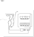
Figure 1 - is the schematic view of the water pocket on the dishwasher. -
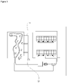
Figure 2 - is the schematic view of the ultrasonic vibration member and the water pocket on the dishwasher. -
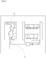
Figure 3 - is the schematic view of the air compressor and the water pocket on the dishwasher. -
Figure 4 - is the schematic view of the mixer and the water pocket on the dishwasher. - The elements illustrated in the figures are numbered as follows:
- 1. Dishwasher
- 2. Body
- 3. Washing tub
- 4. Sump
- 5. Spraying member
- 6. Circulation pump
- 7. Heater
- 8. Multiport valve
- 9. Water pocket
- 10. Heat exchanger
- 11. Water movement means
- 12. Discharge pump
- 13. First valve
- 14. Second valve
- 15. Delivery line
- 16. Ultrasonic vibration member
- 17. Air compressor
- 18. Air delivery line
- 19. Motor
- 20. Mixer
- The dishwasher (1) comprises a body (2); a washing tub (3) which is disposed in the body (2) and wherein the washing process is performed; a sump (4) which is disposed on the base of the washing tub (3) and wherein the water coming from the washing tub (3) is collected; at least one spraying member (5) which is disposed in the washing tub (3) and which sprays the water coming from the sump (4) onto the kitchen items; a circulation pump (6) which enables the water to be transferred from the sump (4) to the spraying member (5); a heater (7) which is disposed on the circulation pump (6); a multiport valve (8) which is disposed between the circulation pump (6) and the spraying member (5) and which directs the water to the spraying member (5); a water pocket (9) which is disposed between the washing tub (3) and the body (2) and wherein water is collected to be used in the washing process; and a heat exchanger (10) which is connected to the sump (4) at one end and to the multiport valve (8) at the other end and which extends into the water pocket (9). The water in the sump (4) is heated by means of the circulation pump (6) and delivered to the spraying members (5). The spraying member (5) which receives the water is determined by means of the multiport valve (8). The hot water used in the washing process is directed to the heat exchanger (10) by means of the multiport valve (8). The hot water flowing through the heat exchanger (10) returns to the sump (4). Thus, the cold water taken into the water pocket (9) is heated by means of the heat exchanger (10).
- The dishwasher (1) of the present invention comprises a water movement means (11) which enables the water collected in the water pocket (9) to flow and thus contact the heat exchanger (10) more in the unit time. By means of the water movement means (11), the mains water collected in the water pocket (9) is kept moving. Thus, the amount of water which contacts the heat exchanger (10) in the unit time increases, which enables the water in the water pocket (9) to be heated more quickly.
- In an embodiment of the present invention, the dishwasher (1) comprises the water movement means (1) composed of a discharge pump (12) which is connected to the sump (4) and which discharges the water in the sump (4), a first valve (13) which is disposed between the discharge pump (12) and the sump (4), a second valve (14) which is connected to the discharge pump (12) and a delivery line (15) which enables the water drawn from the second valve (14) to be delivered to the water pocket (9) and enables the water in the water pocket (9) to be delivered back to the discharge pump (12) via the first valve (13). The clean water received into the sump (4) from the mains is delivered to the discharge pump (12) via the first valve (13). The water drawn from the discharge pump (12) via the second valve (14) is delivered to the water pocket (9) through the delivery line (15). The water drawn again from the water pocket (9) by means of the delivery line (15) is delivered to the second valve (14) through the first valve (13) and the discharge pump (12). Thus, the continuous circulation of water is formed and the water in the water pocket (9) is kept moving.
- In an embodiment of the present invention, the dishwasher (1) comprises the water movement means (11) which is at least one ultrasonic vibration member (16) disposed on the water pocket (9). By means of the ultrasonic vibration member (16) disposed on the water pocket (9), the water is moved thanks to vibrations. Thus, the water contacts the heat exchanger (10) more and heats up more quickly.
- In an embodiment of the present invention, the dishwasher (1) comprises the ultrasonic vibration member (16) disposed along a surface of the water pocket (9). The ultrasonic vibration member (16) is disposed along a surface of the water pocket (9). As the size of the ultrasonic vibration member (16) increases, the vibrations generated by the same and the water movement rate also increase. Thus, the water is enabled to contact the heat exchanger (10) more.
- In an embodiment of the present invention, the dishwasher (1) comprises the water movement means (11) comprising an air compressor (17) which is disposed in the vicinity of the water pocket (9) and at least one air delivery line (18) which is connected to the air compressor (17) at one end and which extends into the water pocket (9) at the other end. By means of the air delivery line (18) connected to the air compressor (17), air bubbles are generated in the water pocket (9) such that the water in the water pocket (9) is kept moving.
- In an embodiment of the present invention, the dishwasher (1) comprises the water movement means (11) which is a mixer (20) extending longitudinally in the water pocket (9) and moved by means of a motor (19). By means of the mixer(20), the water in the water pocket (9) moves continuously and a homogeneous structure is obtained.
- By means of the present invention, a dishwasher is realized, wherein the mains water collected in the water pocket (9) is enabled to move continuously and thus to contact the heat exchanger (10) more in the unit time so as to be heated more quickly. Consequently, savings in both energy and time are provided while heating the water in the water pocket (9).
Claims (6)
- A dishwasher (1) comprising a body (2); a washing tub (3) which is disposed in the body (2) and wherein the washing process is performed; a sump (4) which is disposed on the base of the washing tub (3) and wherein the water coming from the washing tub (3) is collected; at least one spraying member (5) which is disposed in the washing tub (3) and which sprays the water coming from the sump (4) onto the kitchen items; a circulation pump (6) which enables the water to be transferred from the sump (4) to the spraying member (5); a heater (7) which is disposed on the circulation pump (6); a multiport valve (8) which is disposed between the circulation pump (6) and the spraying member (5) and which directs the water to the spraying member (5); a water pocket (9) which is disposed between the washing tub (3) and the body (2) and wherein water is collected to be used in the washing process; and a heat exchanger (10) which is connected to the sump (4) at one end and to the multiport valve (8) at the other end and which extends into the water pocket (9), characterized by a water movement means (11) which enables the water collected in the water pocket (9) to move and thus contact the heat exchanger (10) more in the unit time.
- A dishwasher (1) as in Claim 1, characterized by the water movement means (1) composed of a discharge pump (12) which is connected to the sump (4) and which discharges the water in the sump (4), a first valve (13) which is disposed between the discharge pump (12) and the sump (4), a second valve (14) which is connected to the discharge pump (12) and a delivery line (15) which enables the water drawn from the second valve (14) to be delivered to the water pocket (9) and enables the water in the water pocket (9) to be delivered back to the discharge pump (12) via the first valve (13).
- A dishwasher (1) as in Claim 1, characterized by the water movement means (11) which is at least one ultrasonic vibration member (16) disposed on the water pocket (9).
- A dishwasher (1) as in Claim 3, characterized by the ultrasonic vibration member (16) disposed along a surface of the water pocket (9).
- A dishwasher (1) as in Claim 1, characterized by the water movement means (11) comprising an air compressor (17) which is disposed in the vicinity of the water pocket (9) and at least one air delivery line (18) which is connected to the air compressor (17) at one end and which extends into the water pocket (9) at the other end.
- A dishwasher (1) as in Claim 1, characterized by the water movement means (11) which is a mixer (20) extending longitudinally in the water pocket (9) and moved by means of a motor (19).
Applications Claiming Priority (1)
| Application Number | Priority Date | Filing Date | Title |
|---|---|---|---|
| TR202105976 | 2021-04-02 |
Publications (1)
| Publication Number | Publication Date |
|---|---|
| EP4066721A1 true EP4066721A1 (en) | 2022-10-05 |
Family
ID=83104229
Family Applications (1)
| Application Number | Title | Priority Date | Filing Date |
|---|---|---|---|
| EP22158710.8A Withdrawn EP4066721A1 (en) | 2021-04-02 | 2022-02-25 | A dishwasher comprising a water pocket |
Country Status (1)
| Country | Link |
|---|---|
| EP (1) | EP4066721A1 (en) |
Cited By (1)
| Publication number | Priority date | Publication date | Assignee | Title |
|---|---|---|---|---|
| WO2024078709A1 (en) * | 2022-10-12 | 2024-04-18 | Electrolux Appliances Aktiebolag | Articles treatment machine with tank assembly |
Citations (7)
| Publication number | Priority date | Publication date | Assignee | Title |
|---|---|---|---|---|
| DE102010029873A1 (en) | 2010-06-09 | 2011-12-15 | BSH Bosch und Siemens Hausgeräte GmbH | Domestic appliance e.g. washing machine, has pump for transferring heat energy contained in waste water from water reservoir into heat reservoir, and heat exchanger provided in heat reservoir for heating wash water |
| US20140007767A1 (en) * | 2012-07-06 | 2014-01-09 | Eichenauer Heizelemente Gmbh & Co. Kg | Automatic dishwasher |
| EP2687142A2 (en) * | 2012-07-20 | 2014-01-22 | Indesit Company S.p.A. | Household dish-washing machine |
| EP3639722A1 (en) * | 2018-10-18 | 2020-04-22 | Whirlpool Corporation | Dishwashers having a heat exchanger |
| US20200163526A1 (en) * | 2018-11-27 | 2020-05-28 | Lg Electronics Inc. | Dish washer |
| US20200163520A1 (en) * | 2018-11-27 | 2020-05-28 | Lg Electronics Inc. | Dish washer |
| EP3788934A1 (en) * | 2019-08-13 | 2021-03-10 | Miele & Cie. KG | Dishwasher and method for operating a dishwasher |
-
2022
- 2022-02-25 EP EP22158710.8A patent/EP4066721A1/en not_active Withdrawn
Patent Citations (7)
| Publication number | Priority date | Publication date | Assignee | Title |
|---|---|---|---|---|
| DE102010029873A1 (en) | 2010-06-09 | 2011-12-15 | BSH Bosch und Siemens Hausgeräte GmbH | Domestic appliance e.g. washing machine, has pump for transferring heat energy contained in waste water from water reservoir into heat reservoir, and heat exchanger provided in heat reservoir for heating wash water |
| US20140007767A1 (en) * | 2012-07-06 | 2014-01-09 | Eichenauer Heizelemente Gmbh & Co. Kg | Automatic dishwasher |
| EP2687142A2 (en) * | 2012-07-20 | 2014-01-22 | Indesit Company S.p.A. | Household dish-washing machine |
| EP3639722A1 (en) * | 2018-10-18 | 2020-04-22 | Whirlpool Corporation | Dishwashers having a heat exchanger |
| US20200163526A1 (en) * | 2018-11-27 | 2020-05-28 | Lg Electronics Inc. | Dish washer |
| US20200163520A1 (en) * | 2018-11-27 | 2020-05-28 | Lg Electronics Inc. | Dish washer |
| EP3788934A1 (en) * | 2019-08-13 | 2021-03-10 | Miele & Cie. KG | Dishwasher and method for operating a dishwasher |
Cited By (1)
| Publication number | Priority date | Publication date | Assignee | Title |
|---|---|---|---|---|
| WO2024078709A1 (en) * | 2022-10-12 | 2024-04-18 | Electrolux Appliances Aktiebolag | Articles treatment machine with tank assembly |
Similar Documents
| Publication | Publication Date | Title |
|---|---|---|
| EP2094148B1 (en) | Method of controlling dishwasher | |
| CN211066474U (en) | Dish washing machine | |
| CN107647834B (en) | Heat pump dishwasher | |
| RU2011103711A (en) | DISHWASHING MACHINE WITH TWO CIRCULATION CIRCUITS | |
| CN101273871A (en) | Dishwasher and its control method | |
| EP2662013A1 (en) | A dishwashing machine with a heat-pump drying device and associated method | |
| CN100558284C (en) | dish washer | |
| CN108024687B (en) | Warewasher with heat recovery system | |
| KR100843515B1 (en) | Waste heat exchange device of dish washer | |
| CN218295834U (en) | Self-cleaning integrated stove | |
| KR100908003B1 (en) | Dish washer | |
| CN218510942U (en) | Self-cleaning integrated stove | |
| EP4059409B1 (en) | A dishwasher providing heat recovery | |
| CN205585971U (en) | Dishwasher | |
| EP4066722B1 (en) | A dishwasher providing heat recovery | |
| EP4461192B1 (en) | A dishwasher comprising a heat pump | |
| EP3801178B1 (en) | Heat pump dishwasher with enhanced evaporator capacity | |
| EP3801179B1 (en) | Heat pump dishwasher with enhanced evaporator efficiency | |
| TR2021005976A2 (en) | A DISHWASHER WITH WATER POCKET | |
| CN217031290U (en) | Wind wheel cleaning structure of integrated stove and integrated stove | |
| CN101090663A (en) | Dish washer and steam providing unit for the same | |
| EP2201884A1 (en) | Method for preventing kitchenware articles from breaking during washing in a dishwasher | |
| EP3855997B1 (en) | A heat pump dishwasher with reduced energy consumption | |
| KR940008403Y1 (en) | Dishwasher with hot water steam injection function | |
| WO2018219469A1 (en) | Dishwasher with improved cleaning/drying performance and improved energy efficiency |
Legal Events
| Date | Code | Title | Description |
|---|---|---|---|
| PUAI | Public reference made under article 153(3) epc to a published international application that has entered the european phase |
Free format text: ORIGINAL CODE: 0009012 |
|
| STAA | Information on the status of an ep patent application or granted ep patent |
Free format text: STATUS: REQUEST FOR EXAMINATION WAS MADE |
|
| 17P | Request for examination filed |
Effective date: 20220225 |
|
| AK | Designated contracting states |
Kind code of ref document: A1 Designated state(s): AL AT BE BG CH CY CZ DE DK EE ES FI FR GB GR HR HU IE IS IT LI LT LU LV MC MK MT NL NO PL PT RO RS SE SI SK SM TR |
|
| STAA | Information on the status of an ep patent application or granted ep patent |
Free format text: STATUS: THE APPLICATION IS DEEMED TO BE WITHDRAWN |
|
| 18D | Application deemed to be withdrawn |
Effective date: 20230406 |