EP4066678A1 - Slide fastener - Google Patents
Slide fastener Download PDFInfo
- Publication number
- EP4066678A1 EP4066678A1 EP19954326.5A EP19954326A EP4066678A1 EP 4066678 A1 EP4066678 A1 EP 4066678A1 EP 19954326 A EP19954326 A EP 19954326A EP 4066678 A1 EP4066678 A1 EP 4066678A1
- Authority
- EP
- European Patent Office
- Prior art keywords
- slider
- wall
- tape
- fastener
- slide fastener
- Prior art date
- Legal status (The legal status is an assumption and is not a legal conclusion. Google has not performed a legal analysis and makes no representation as to the accuracy of the status listed.)
- Granted
Links
Images





Classifications
-
- A—HUMAN NECESSITIES
- A44—HABERDASHERY; JEWELLERY
- A44B—BUTTONS, PINS, BUCKLES, SLIDE FASTENERS, OR THE LIKE
- A44B19/00—Slide fasteners
- A44B19/24—Details
- A44B19/26—Sliders
- A44B19/265—Sliders with means for preventing the accidental intrusion of material into the slider body, e.g. with shield or guard
-
- A—HUMAN NECESSITIES
- A44—HABERDASHERY; JEWELLERY
- A44B—BUTTONS, PINS, BUCKLES, SLIDE FASTENERS, OR THE LIKE
- A44B19/00—Slide fasteners
- A44B19/02—Slide fasteners with a series of separate interlocking members secured to each stringer tape
Definitions
- the present disclosure is related to slide fasteners.
- Patent literature 1 discloses that an elongated protrusion is arranged on an inner surface of a fastener tape to prevent jamming of a lining in a slider. Sewing or bonding of a cord/linear member made of synthetic resin, or thermal-bonding of a linear member made of synthetic resin are described as exemplary ways of forming the elongated protrusion.
- Fig. 3 of the literature illustrates an embodiment where an elongated protrusion is formed by partially laminating a fastener tape.
- Patent literature 2 discloses that a slider is provided with a V-shaped or U-shaped recess so that jamming of a cloth is prevented.
- Patent literature 3 discloses that a " plastically deformable " core is inserted into an inside of a tubular woven portion for a purpose of improving a shape-retaining characteristic of the slide fastener (See Claim 10, para. 0015 and Fig. 3 ), not directly related to a technical problem of jamming of a cloth though.
- the present inventors have newly identified a technical problem to prevent jamming of a cloth in a slider at both sides of a fastener tape while suppressing a bulkiness of a wall that is configured to prevent jamming of a cloth in a slider.
- a slide fastener includes: a pair of fastener stringers including a fastener tape and a fastener element arranged on a side-edge of the fastener tape, the fastener tape having tape upper and lower surfaces which define a tape thickness; and a slider to be moved to open or close the pair of fastener stringers, the slider including a slider upper portion arranged at the same side as the tape upper surface, a slider lower portion arranged at the same side as the tape lower surface, and a connecting portion connecting the slider upper portion and the slider lower portion.
- At least one fastener tape is provided with a wall configured to prevent jamming of a cloth, the wall being arranged to be spaced apart from the fastener element.
- the wall includes a wall upper portion arranged at the same side as the tape upper surface and protruding from the tape upper surface, and a wall lower portion arranged at the same side as the tape lower surface and protruding from the tape lower surface.
- the slider upper portion is positioned adjacent to the wall upper portion and the slider lower portion is positioned adjacent to the wall lower portion so that jamming of a cloth in the slider is prevented at both sides of the tape upper and lower surfaces.
- the wall upper portion is arranged to touch the slider upper portion at least partially and/or the wall lower portion is arranged to touch the slider lower portion at least partially.
- a distance between the slider upper portion and the wall is equal to or less than 1 times a width of the fastener element in the same direction as that distance; and/or a distance between the slider lower portion and the wall is equal to or less than 1 times a width of the fastener element in the same direction as said distance.
- the slider has a slit for passing the fastener tape, the slit being defined between opposed portions of the slider upper portion and the slider lower portion, and a thickness of the wall in an Up-Down direction is in a range between 0.75 times and 5 times a width of the slit in the Up-Down direction.
- the thickness of the wall in the Up-Down direction is in a range between 1 times and 5 times the width of the slit in the Up-Down direction.
- the wall is flexible.
- the wall includes a tubular structure of the fastener tape and a core enclosed in the tubular structure.
- the core is flexible.
- the tubular structure includes a warp thread having a thickness greater than a thickness of a weft thread in the fastener tape.
- the wall is a resin or metal part attached to the fastener tape.
- the slider includes a slider body including an upper wing, a lower wing, and a connecting post connecting the upper wing and the lower wing, the upper and lower wings being arranged to face one another, each of the upper wing and the lower wing has a front end in which left and right shoulders extends along a Left-Right direction and a central recess is recessed rearward at a position between the left and right shoulders, the Left-Right direction being orthogonal to a movement direction of the slider body and the tape upper and lower surfaces.
- the upper wing has a flange protruding toward the lower wing to define a slit for passing the fastener tape, and a front end of the flange is connected to the front end of the upper wing.
- jamming of a cloth in a slider can be prevented at both sides of a fastener tape while suppressing a bulkiness of a wall that is configured to prevent jamming of a cloth in a slider.
- Slide fastener 1 is an elongated web having a lengthwise direction, a crosswise direction, and a thickness direction.
- the slide fastener 1 includes a pair of fastener stringers 2,4, and a slider 5 to be moved to open or close the pair of fastener stringers 2,4.
- the fastener stringer 2 is a component in which a fastener element 30 is secured to a side-edge 13 of a belt-like fastener tape 10 along the lengthwise direction.
- the fastener stringer 4 is a component in which a fastener element 40 is secured to a side-edge 23 of a belt-like fastener tape 20 along the lengthwise direction.
- the slider 5 is engaged with the fastener elements 30 and 40 in a slidable fashion.
- the slider 5 moves frontward so that the pair of fastener stringers 2,4 are closed (the fastener elements 30,40 are engaged), and the slider 5 moves rearward so that the pair of fastener stringers 2,4 are separated (the fastener elements 30,40 are disengaged).
- Up-Down direction is equal to a thickness direction of the slide fastener 1.
- Front-Rear direction is orthogonal to the Up-Down direction, and is equal to the lengthwise direction of the slide fastener 1 and the movement direction of the slider 5.
- Left-Right direction is orthogonal to the Up-Down direction and the Front-Rear direction, and is equal to the crosswise direction of the slide fastener 1.
- the fastener tape 10,20 is, for example, a woven fabric or knitted fabric or combination thereof and is an elongated belt-like flexible fabric.
- the fastener tape 10,20 is made of plural tape structures.
- a tape structure such as a plain weave, twill weave, warp rib weave, or hollow weave (double weave) is configured by plural warp threads and one or plural weft threads.
- a tape structure is configured by a warp knitted structure such as a chain weave, tricot weave and satin weave.
- a core thread is secured to the side-edge 13,23 of the fastener tape 10,20 along the lengthwise direction, thereby increasing the attachment strength of the fastener element 30,40 to the fastener tape 10,20, for example.
- Structures, configurations and thickness of the fastener tape can be variously determined by a skilled person in the art.
- the fastener tape 10 has a tape thickness defined by a distance between a tape upper surface 11 and a tape lower surface 12 illustrated in Fig. 2 .
- the fastener tape 20 has a tape thickness defined by a distance between a tape upper surface 21 and a tape lower surface 22 illustrated in Fig. 2 .
- the slider 5 has a slider upper portion 5A arranged at the same side as the tape upper surface 11,21 of the fastener tape 10,20, a slider lower portion 5B arranged at the same side as the tape lower surface 12,22 of the fastener tape 10,20, and a connecting portion 5C connecting the slider upper portion 5A and the slider lower portion 5B.
- the slider 5 is further provided with slits S1,S2, defined between opposed portions of the slider upper and lower portions 5A and 5B, for permitting the fastener tape 10,20 to pass there-through. Width of the slit S1,S2 in the Up-Down direction (i.e. Slit-width) is equal to a distance between a portion (e.g.
- the width of the slit S1,S2 in the Up-Down direction is greater than a thickness, in the Up-Down direction, of a portion of the fastener tape 10,20 provided in the slit S1,S2, but should not be limited to this.
- the opposed portions of the slider top and lower portions 5A and 5B, defining the slit S1,S2 may be in contact with the respective upper and lower surfaces 11,21 and 12,22 of the fastener tape 10,20 when the slider 5 moves frontward or rearward.
- the slider 5 is configured by a single component of a slider body 5j (with an optional pull tab 6 attached thereto).
- the slider body 5j has upper and lower wings 51 and 52 arranged in the Up-Down direction to face each other, a connecting post 53 connecting the upper wing 51 and the lower wing 52, a pull-attachment column 54 arranged on the upper wing 51, and a pull-attachment column 55 arranged on the lower wing 52.
- the slider upper portion 5A is configured by the upper wing 51 and the pull-attachment column 54.
- the slider lower portion 5B is configured by the lower wing 52 and the pull-attachment column 55.
- the connecting portion 5C is configured by the connecting post 53. Note that, Figs. 3-5 shows a condition before the pull-attachment columns 54,55 are plastically deformed.
- Y-shaped element passage is formed in the slider body 5j which is bifurcated by the connecting post 53.
- a pair of front openings 58A,58B are arranged at the left and right sides of the connecting post 53.
- a rear opening 59 is arranged at the opposite side of the front openings 58A,58B.
- the front openings 58A,58B are arranged to sandwich the connecting post 53 in the Left-Right direction orthogonal to the movement direction of the slider body 5j and the tape upper and lower surfaces 11,12,21,22.
- Separated fastener elements 30,40 move into and out from the slider body 5j via the front openings 58A,58B.
- Engaged fastener elements 30,40 move into and out from the slider body 5j via the rear opening 59.
- the upper wing 51 is provided with flanges 56p,56q which are protruded toward the lower wing 52 so as to define respective slits S1,S2 for passing the fastener tape 10,20.
- the lower wing 52 is provided with flanges 57p,57q protruded toward the upper wing 51 so as to define respective slits S1,S2 for passing the fastener tape 10,20.
- the slit S1,S2 extends in the Front-Rear direction to communicate the front opening 58A or 58B and the rear opening 59. Passage for the left or right fastener element 30,40 is provided between the connecting post 53 and a respective one of the flanges 56p,56q.
- Passage for the engaged left and right fastener elements 30,40 is provided in a space rearward of the connecting post 53 and between the flanges 56p,56q.
- the height of the protruded flange 56p,56q is greater than the height of the protruded flange 57p,57q in the illustrated example, but a case is envisioned where they are at the same height.
- the slit S1 has a slit width S10 that corresponds to a distance between the flange 56p of the upper wing 51 and the flange 57p of the lower wing 52 in the slider 5.
- the slit width S10 corresponds to a distance between the slider upper portion 5A and the slider lower portion 5B of a space in the slider 5 where the fastener tape 10 passes through.
- the slit S2 has a slit width S20 which corresponds to a distance between the flange 56q of the upper wing 51 and the flange 57q of the lower wing 52 in the slider 5.
- the slit width S20 corresponds to a distance between the slider upper portion 5A and the slider lower portion 5B of a space in the slider 5 where the fastener tape 20 passes through.
- the slit width S10,S20 is greater than a minimum value of the tape thickness of the fastener tape 10,20.
- the fastener tape 10 has a wall 14 arranged to be spaced apart from the fastener element 30 with an interspace.
- the fastener tape 20 has a wall 24 arranged to be spaced apart from the fastener element 40 with an interspace.
- the above-described interspace i.e. a distance between an edge of the fastener element 30 at the side of the wall 14 and an edge of the wall 14 at the side of the fastener element 30 is equal to or less than a width of the fastener element 30 in the Left-Right direction.
- the thickness of the wall 14 is greater than the tape-thickness of the other portion of the fastener tape 10.
- the thickness of the wall 24 is greater than the tape-thickness of the other portion of the fastener tape 20.
- the wall 14,24 has a wall upper portion 14A,24A protruding from the tape upper surface 11,21 in the thickness direction of the fastener tape 10,20, and a wall lower portion 14B,24B protruding from the tape lower surface 12,22 in the thickness direction of the fastener tape 10,20.
- the walls 14,24 are provided to prevent jamming of a cloth.
- the thickness of the wall 14,24 in the Up-Down direction may be in a range between 0.75 times and 5 times the width of the slit S1,S2 in the Up-Down direction (Slit width S10,S20).
- the thickness of the wall 14,24 in the Up-Down direction is greater than the slit width S10,S20. That is, the thickness of the wall 14,24 in the Up-Down direction is in a range between 1 times and 5 times the width of the slit S1,S2 in the Up-Down direction (the slit width S10,S20).
- the thickness of the wall 14,24 in the Up-Down direction is twice the width of the slit S1,S2 in the Up-Down direction (the slit width S10,S20).
- the wall 14,24 has a tubular structure 15,25 of the fastener tape 10,20 and a core 16,26 enclosed in this tubular structure 15,25.
- Fig. 7 is a schematic cross-sectional view of the fastener tape 10,20, depicting a condition of plural warp threads relative to a weft thread.
- the tubular structure 15,25 includes plural warp threads 93 per a weft thread.
- the warp threads 93 are arranged to surround the core 16,26 in its periphery.
- the tubular structure 15,25 is based on a hollow weave (double weave). Note that a method of forming a hollow weave is known for skilled ones in the art, and thus detail descriptions will be omitted.
- the wall 14,24 is configured to include the weft thread and the warp threads likewise the other portion of the fastener tape 10,20, thus suppressing that more attention is to be paid to the wall 14,24 when the tape upper surface 11,21 or the tape lower surface 12,22 is looked at.
- the wall 14,24 is formed simultaneously when the fastener tape 10,20 is woven, allowing precise positioning of the wall 14,24 and omission of additional step of attaching the wall 14,24 onto the fastener tape 10,20. Moreover, there is no risk of removal of the wall 14,24 off the fastener tape 10,20.
- the wall 14,24 may be flexible, preferably. In such a case, even if the slider 5 slides while touching the wall 14,24, not all stress is applied from the slider 5 to the wall 14,24, thus a functionality of preventing jamming of a cloth is obtained without sacrificing a sliding property. Also, it is avoided or suppressed that the wall 14,24 is worn due to the contact between the slider 5 and the wall 14,24.
- the thickness of the warp thread 93 in the tubular structure 15,25 of the wall 14,24 is greater than the thickness of the warp thread 91 in the other portion.
- the thickness of the warp thread 93 in the tubular structure 15,25 of the wall 14,24 is greater than (e.g. 3 times) the thickness of the weft thread.
- the core 16,26 of the wall 14,24 is a knitted cord and includes a bundle of threads covered by skin threads in its periphery.
- the strength of the core 16,26 is greater than the strength of a core thread arranged on a side-edge 13,23 of the fastener tape 10,20 along the lengthwise direction.
- the core thread is a twisted cord and formed by bundling and twisting plural threads. The core thread can contract in a given extent.
- Warp threads in a hollow weave (double weave) around this core thread are the same as and have the same thickness as the weft threads.
- the thickness of the warp threads used in the wall 14,24 may be equal to or greater than 3 times the thickness of the weft thread in the above descriptions, but should not be limited to this.
- the thickness of the warp thread used for the wall may be equal to the thickness of the weft thread.
- the core 16, 26 has been described as a knitted cord, but should not be limited to this and can be a metal wire or resin wire.
- the fastener element 30,40 is, for example, a coil element which is a mono-filament wound in helix but can be configured by arrangement of metal or resin elements.
- the fastener element 30,40 can be attached to the fastener tape 10,20, in accordance with its type, through swaging, injection-molding, or sewing. Embodiment is also envisioned where the fastener element 30,40 is woven together in the structure of the fastener tape 10,20.
- Rear stop 7 can be attached to cover the left and right fastener elements 30, 40.
- Front stop 8 can be attached to the fastener element 30.
- the front stop 9 can be attached to the fastener element 40. Note that the rear stop 7, the front stop 8, and the front stop 9 can be attached to cover not only the fastener element but also to cover at least a portion of the wall 14,28.
- the tape upper surface 11,21 may be positioned at an outer side of a garment to which the slide fastener 1 is sewn, and the tape lower surface 12,22 may be positioned at an inner side of the garment. It is however envisioned that this relationship is reversed. It is not possible to see if a cloth of garment is on a moving path of the slider 5 in the internal space of the garment. Therefore, that cloth is likely be jammed in the slider 5. Whereas, one does not necessarily take a close look at the slider 5 or its periphery when operating and moving the slider 5. That is, there is a possibility that a cloth of garment can be jammed in the slider 5 even in the outside of the garment.
- the slide fastener 1 can be used for opening and closing not only for garments but also for tents or sleeping bags.
- the sleeping bag is configured by filling heat storage material inside pockets made of a thin cloth. It is envisioned that the slider 5 is operated by a hand only without being looked at, and thus the slide fastener 1 according to the present disclosure would be suitably used.
- a movable range R5 (See Fig. 1 ) of the slider 5.
- the slider upper portion 5A is positioned adjacent to the wall upper portion 14A,24A and the slider lower portion 5B is positioned adjacent to the wall lower portion 14B,24B, thus preventing jamming of a cloth in the slider 5 at both sides of the tape upper and lower surfaces 11,12,21,22.
- the respective tape upper and lower surfaces are provided with a solid portion of the wall 14,24 which is necessary for ensuring a solidity of the wall 14,24.
- the movable range R5 of the slider 5 is, typically, a range between the rear stop 7 and the front stop 8,9, but one or both stop members can be omitted in some cases.
- a distance between the slider upper portion 5A and the wall 14 is in a range of 0-1 times the width of the fastener element 30,40 in the same direction as that distance (i.e. in the Left-Right direction); and/or a distance between the slider lower portion 5B and the wall 14 is in a range of 0-1 times the width of the fastener element 30,40 in the same direction as said distance (i.e. in the Left-Right direction).
- the slider upper portion 5A and the wall 14 are in contact each another. The same applies to the relationship of the slider lower portion 5B and the wall 14.
- the wall upper portion 14A,24A is arranged to touch the slider upper portion 5A and/or the wall lower portion 14B,24B is arranged to touch the slider lower portion 5B, not necessarily limited to this tough.
- the wall 14,24 and the slider 5 are in contact each another. A cloth is more effectively prevented from being positioned frontward of the front opening 58A,58B of the slider 5, rearward of the rear opening 59 of the slider 5 and adjacent to the slit S1,S2 of the slider 5.
- the wall upper portion 14A,24A and the slider upper portion 5A and contact between the wall lower portion 14B,24B and the slider lower portion 5B are contact between the wall upper portion 14A,24A and the slider upper portion 5A and contact between the wall lower portion 14B,24B and the slider lower portion 5B.
- the wall upper portion 14A,24A and at least a side surface of an end of the slider upper portion 5A at the side of the rear opening touch one another.
- the wall lower portion 14B,24B and at least a side surface of an end of the slider lower portion 5B at the side of the rear opening touch one another.
- Such arrangement would be particularly desirable for a case where jamming is envisioned when a slider is pulled rearward.
- the wall upper portion 14A,24A and at least a side surface of an end of the slider upper portion 5A at the side of the front opening touch each other. It is desirable that the wall bottom portion 14B,24B and at least a side surface of an end of the slider lower portion 5B at the side of the front opening touch each other. Such arrangement would be particularly desirable for a case where jamming is envisioned when a slider is pulled frontward.
- the wall upper portion 14A,24A and a side surface of the slider upper portion 5A, extending substantially across the entire length between the front opening and the rear opening, are in contact as shown in Fig. 1 .
- the wall lower portion 14B,24B and a side surface of the slider lower portion 5B, extending substantially across the entire length between the front opening and the rear opening are in contact.
- a corner of a flange of the slider upper portion 5A is kept touching the round surface of the wall upper portion 14A,24A as shown in Fig. 2 .
- a corner of a flange of the slider upper portion 5A is kept touching the round surface of the wall lower portion 14B,24B.
- the front end of the upper wing 51 has left and right shoulders 51p,51q extending in the Left-Right direction and a central recess 51r recessed rearward at a position between the left and right shoulders 51p,51q.
- the front end of the lower wing 52 has left and right shoulders 52p,52q extending in the Left-Right direction and a central recess 52r recessed rearward at a position between the left and right shoulders 52p,52q.
- the left or right shoulder is a linear portion that extends linearly in the Left-Right direction.
- the front end of the flange 56p,56q is coupled to the front end of the upper wing 51.
- the front end of the flange 56p,56q is coupled to the front end of the upper wing 51.
- left and right walls 14, 24 are arranged as described below, a possibility is low that a cloth traverses the wall 14,24 to reach the flange 56p,56q and is nipped between the flange 56p,56q and the fastener element 30,40.
- the descriptions made for the upper wing 51 holds true for the lower wing 52, and thus overlapping description is omitted.
- the flange 56p,56q has a flange rear portion 56p1,56q1 and a flange sloped portion 56p2,56q2 arranged frontward of the flange rear portion 56p1,56q1.
- the flange rear portion 56p1,56q1 extend in parallel to the movement direction of the slider 5.
- the interspace between the flange rear portions 56p1,56q1 is constant along the Front-Rear direction.
- the flange sloped portion 56p2,56q2 extends obliquely frontward from the flange rear portion 56p1,56q1.
- the interspace between the flange sloped portions 56p2,56q2 increases frontward.
- an angle between the flange rear portion 56p1,56q1 and the flange sloped portion 56p2,56q2 is in a range between 15° to 35°.
- the fastener tapes 10,20 are respectively provided with the walls 14,24, thus preventing a cloth from moving in a direction toward the central line AX of the slide fastener 1 in the Left-Right direction shown in Fig. 1 (see the arrows).
- this case cannot cope with a case where a cloth is positioned in front of the slider 5 between the fastener elements 30,40.
- the front end of the slider 5 is provided with the central recess 51r,52r and, when the slider 5 moves frontward, a cloth in front of the slider 5 is guided into the central recess 51r,52r, thus preventing a cloth from entering into a space between the slider 5 and the fastener element, i.e. jamming of a cloth in the slider 5 is prevented.
- the walls 14,24 are integrally formed with the fastener tape 10,20 as shown in Fig. 2
- it may be configured by attaching a separate part to the fastener tape 10,20.
- a first core thread is sewn onto the tape upper surface and a second core thread is sewn onto the tape lower surface so that a wall protruding in the Up-Down direction is formed.
- the respective tape upper and lower surfaces are provided with a solid portion of the wall 14,24 which is necessary for ensuring a solidity of the wall 14,24. Therefore, jamming of a cloth in the slider 5 can be prevented at both sides of the fastener tape 10,20 while suppressing a bulkiness of the wall.
- Fig. 8 illustrates that the wall 14,24 is divided into plural islands 14i,24i. Even in such a case, similar effects would be achieved as the above-described embodiments.
- Each island 14i,24i is elongated in the Front-Rear direction, but should not be limited to this shape.
- the islands 14i,24i can be attached to the fastener tape 10,20 through swaging, injection molding, sewing and so on likewise the fastener element 30,40. Similar to the above-described cases, each island 14i,24i may have a tubular structure 15,25 and a core 16,26 enclosed in this tubular structure 15,25. Needless to say, it is possible to employ metal-made or resin-made islands.
- Fig. 9 shows an embodiment where the walls 14,24 are resin or metal parts and attached to the fastener tape 10,20 through injection molding or swaging.
- Material of the wall 14,24 would be various and a use of core such as a cord is not mandatory.
- Fig. 10 shows an embodiment where the slider 5 is configured by a slider body 5j and a cover 5u attached thereto.
- the cover 5u is a retrofit component attached to the slider body 5j to prevent jamming of a cloth in the slider body 5j.
- the cover 5u is configured to prevent jamming of a cloth in the slider 5 when the slider 5 moves frontward (see Fig. 10 ) and/or to prevent jamming of a cloth in the slider 5 when the slider 5 moves rearward.
- the cover 5u is constructed, for example, from a cover upper portion covering the slider upper portion 5A of the slider body 5j from above, a cover lower portion covering the slider lower portion 5B of the slider body 5j from below, and a connecting portion interconnecting the cover upper portion and the cover lower portion.
- the cover top and lower portions are coupled by a method such as a mechanical fit in the connecting portion such that the slider body 5j is accommodated in the slider body 5j.
- the cover upper portion is a part of the slider upper portion 5A arranged at the same side as the tape upper surface 11,21.
- the cover lower portion is a part of the slider lower portion 5B arranged at the same side as the tape lower surface 12,22.
- the connecting portion interconnecting the cover upper portion and the cover lower portion is a part of the connecting portion 5C interconnecting the slider upper portion 5A and the slider lower portion 5B.
- the cover 5u is configured to define a space for holding the slider body 5j, a left passage 81A for the left fastener element, and a right passage 81B for the right fastener element.
- the left passage 81A is in spatial communication with a left passage 71A at the left side of the connecting post 53 of the slider body 5j.
- the right passage 81B is in spatial communication with a right passage 71B at the right side of the connecting post 53 of the slider body 5j.
- the left and right passages 71A,71B in the slider body 5j are in communication with a passage 71C provided rearward of the connecting post 53 of the slider body 5j.
- Such a cover 5u has been known for a skilled person as disclosed in International Publication No. 2016/035125 (which is incorporated herein by reference), and thus detail descriptions will be omitted.
- the slider body 5j is not a special/dedicated slider shown in Figs. 3-6 , but is a commonly used slider.
- the upper portion of the slider 5 i.e. the upper portion of the cover 5u of the slider 5
- the lower portion of the slider 5 i.e. the lower portion of the cover 5u of the slider 5
- the lower portion of the wall 14,24 is positioned adjacent to (e.g. touches) the lower portion of the wall 14,24 so that jamming of a cloth in the slider 5 is prevented at both sides of the tape upper and lower surfaces. Therefore, similar effects as the above-described embodiments can be obtained in the present embodiment either.
Landscapes
- Slide Fasteners (AREA)
Abstract
Description
- The present disclosure is related to slide fasteners.
-
Patent literature 1 discloses that an elongated protrusion is arranged on an inner surface of a fastener tape to prevent jamming of a lining in a slider. Sewing or bonding of a cord/linear member made of synthetic resin, or thermal-bonding of a linear member made of synthetic resin are described as exemplary ways of forming the elongated protrusion.Fig. 3 of the literature illustrates an embodiment where an elongated protrusion is formed by partially laminating a fastener tape. -
Patent literature 2 discloses that a slider is provided with a V-shaped or U-shaped recess so that jamming of a cloth is prevented. -
Patent literature 3 discloses that a "plastically deformable" core is inserted into an inside of a tubular woven portion for a purpose of improving a shape-retaining characteristic of the slide fastener (SeeClaim 10, para. 0015 andFig. 3 ), not directly related to a technical problem of jamming of a cloth though. -
- [Patent literature 1]
Japanese Utility-model Application Laid-open No. 60-105409 - [Patent literature 2]
Japanese Patent Application Laid-open No. 2005-160785 - [Patent literature 3]
Japanese Patent No. 5403639 - In a case where an elongated protrusion is provided only at an inner side of a fastener tape as disclosed in
Patent literature 1, there is a possibility that jamming of a cloth is not prevented because, when a slide fastener is subjected to a deformation such as bending or twisting, the elongated protrusion would also be deformed. In order to cope with such a problem, one may consider to increase solidity of the elongated protrusion, but this is not a practical approach as the elongated protrusion can be unacceptably large at the inner side of the fastener tape. Also, it is first of all not possible to prevent jamming of a cloth in a slider at the outer side of fastener tape even if the elongated protrusion is provided at the inner side of the fastener tape as disclosed in thepatent literature 1. - The present inventors have newly identified a technical problem to prevent jamming of a cloth in a slider at both sides of a fastener tape while suppressing a bulkiness of a wall that is configured to prevent jamming of a cloth in a slider.
- A slide fastener according to an aspect of the present disclosure includes: a pair of fastener stringers including a fastener tape and a fastener element arranged on a side-edge of the fastener tape, the fastener tape having tape upper and lower surfaces which define a tape thickness; and a slider to be moved to open or close the pair of fastener stringers, the slider including a slider upper portion arranged at the same side as the tape upper surface, a slider lower portion arranged at the same side as the tape lower surface, and a connecting portion connecting the slider upper portion and the slider lower portion. At least one fastener tape is provided with a wall configured to prevent jamming of a cloth, the wall being arranged to be spaced apart from the fastener element. The wall includes a wall upper portion arranged at the same side as the tape upper surface and protruding from the tape upper surface, and a wall lower portion arranged at the same side as the tape lower surface and protruding from the tape lower surface. In at least a part of a movable range of the slider, the slider upper portion is positioned adjacent to the wall upper portion and the slider lower portion is positioned adjacent to the wall lower portion so that jamming of a cloth in the slider is prevented at both sides of the tape upper and lower surfaces.
- In some embodiments, the wall upper portion is arranged to touch the slider upper portion at least partially and/or the wall lower portion is arranged to touch the slider lower portion at least partially.
- In some embodiments, a distance between the slider upper portion and the wall is equal to or less than 1 times a width of the fastener element in the same direction as that distance; and/or a distance between the slider lower portion and the wall is equal to or less than 1 times a width of the fastener element in the same direction as said distance.
- In some embodiments, the slider has a slit for passing the fastener tape, the slit being defined between opposed portions of the slider upper portion and the slider lower portion, and a thickness of the wall in an Up-Down direction is in a range between 0.75 times and 5 times a width of the slit in the Up-Down direction.
- In some embodiments, the thickness of the wall in the Up-Down direction is in a range between 1 times and 5 times the width of the slit in the Up-Down direction.
- In some embodiments, the wall is flexible. In some embodiments, the wall includes a tubular structure of the fastener tape and a core enclosed in the tubular structure. In some embodiments, the core is flexible. In some embodiments, the tubular structure includes a warp thread having a thickness greater than a thickness of a weft thread in the fastener tape.
- In some embodiments, the wall is a resin or metal part attached to the fastener tape.
- In some embodiments, the slider includes a slider body including an upper wing, a lower wing, and a connecting post connecting the upper wing and the lower wing, the upper and lower wings being arranged to face one another, each of the upper wing and the lower wing has a front end in which left and right shoulders extends along a Left-Right direction and a central recess is recessed rearward at a position between the left and right shoulders, the Left-Right direction being orthogonal to a movement direction of the slider body and the tape upper and lower surfaces.
- In some embodiments, the upper wing has a flange protruding toward the lower wing to define a slit for passing the fastener tape, and a front end of the flange is connected to the front end of the upper wing.
- According to an aspect of the present disclosure, jamming of a cloth in a slider can be prevented at both sides of a fastener tape while suppressing a bulkiness of a wall that is configured to prevent jamming of a cloth in a slider.
-
- [
Fig. 1] Fig. 1 is a schematic top view of a closed slide fastener according to an aspect of the present disclosure. - [
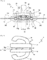
Fig. 2] Fig. 2 is a schematic cross-sectional view of a slide fastener shown inFig. 1 , illustrating a slider viewed from a rear side thereof. - [
Fig. 3] Fig. 3 is a side view of a slider according to an aspect of the present disclosure. - [
Fig. 4] Fig. 4 is a front side view of a slider shown inFig. 3 . - [
Fig. 5] Fig. 5 is a rear side view of a slide shown inFig.3 . - [
Fig. 6] Fig. 6 is a cross-sectional view of a slider shown inFig.3 , illustrating an inner surface of an upper wing. - [
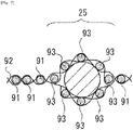
Fig. 7] Fig. 7 is a view depicting a schematic configuration of a wall according to an aspect of the present disclosure. - [
Fig. 8] Fig. 8 is a schematic partial top view of a slide fastener according to another aspect of the present disclosure. - [
Fig. 9] Fig. 9 is a schematic cross-sectional view of a slide fastener shown inFig. 8 . - [
Fig. 10] Fig. 10 is a view depicting a schematic configuration of a slider according to another aspect of the present disclosure, a cover separable in Up-Down direction being attached to a slider body. - Hereinafter, various embodiments and features will be described with reference to
Figs. 1 to 10 . A skilled person would be able to combine respective embodiments and/or respective features without requiring excess descriptions, and would appreciate synergistic effects of such combinations. Overlapping descriptions among the embodiments would be basically omitted. Referenced drawings are mainly for describing inventions, and may possibly be simplified for the sake of convenience of illustration. Individual features will be understood as a universal feature which is not only effective to slide fasteners disclosed in the present specification but also effective to other various slide fasteners not disclosed in the present specification. -
Slide fastener 1 is an elongated web having a lengthwise direction, a crosswise direction, and a thickness direction. Theslide fastener 1 includes a pair offastener stringers 2,4, and aslider 5 to be moved to open or close the pair offastener stringers 2,4. Thefastener stringer 2 is a component in which afastener element 30 is secured to a side-edge 13 of a belt-like fastener tape 10 along the lengthwise direction. Similarly, the fastener stringer 4 is a component in which afastener element 40 is secured to a side-edge 23 of a belt-like fastener tape 20 along the lengthwise direction. Theslider 5 is engaged with thefastener elements slider 5 moves frontward so that the pair offastener stringers 2,4 are closed (thefastener elements slider 5 moves rearward so that the pair offastener stringers 2,4 are separated (thefastener elements - In the present specification, Up-Down direction is equal to a thickness direction of the
slide fastener 1. Front-Rear direction is orthogonal to the Up-Down direction, and is equal to the lengthwise direction of theslide fastener 1 and the movement direction of theslider 5. Left-Right direction is orthogonal to the Up-Down direction and the Front-Rear direction, and is equal to the crosswise direction of theslide fastener 1. - The
fastener tape fastener tape fastener tape edge fastener tape fastener element fastener tape - The
fastener tape 10 has a tape thickness defined by a distance between a tapeupper surface 11 and a tapelower surface 12 illustrated inFig. 2 . Thefastener tape 20 has a tape thickness defined by a distance between a tapeupper surface 21 and a tapelower surface 22 illustrated inFig. 2 . - The
slider 5 has a sliderupper portion 5A arranged at the same side as the tapeupper surface fastener tape lower portion 5B arranged at the same side as the tapelower surface fastener tape portion 5C connecting the sliderupper portion 5A and the sliderlower portion 5B. Theslider 5 is further provided with slits S1,S2, defined between opposed portions of the slider upper andlower portions fastener tape upper portion 5A and a portion (e.g. a flange) of the sliderlower portion 5B which define the slit S1,S2. Typically, the width of the slit S1,S2 in the Up-Down direction (i.e. the slit-width) is greater than a thickness, in the Up-Down direction, of a portion of thefastener tape lower portions lower surfaces fastener tape slider 5 moves frontward or rearward. - For example, as shown in
Figs. 2-6 , theslider 5 is configured by a single component of aslider body 5j (with an optional pull tab 6 attached thereto). Theslider body 5j has upper andlower wings post 53 connecting theupper wing 51 and thelower wing 52, a pull-attachment column 54 arranged on theupper wing 51, and a pull-attachment column 55 arranged on thelower wing 52. The sliderupper portion 5A is configured by theupper wing 51 and the pull-attachment column 54. The sliderlower portion 5B is configured by thelower wing 52 and the pull-attachment column 55. The connectingportion 5C is configured by the connectingpost 53. Note that,Figs. 3-5 shows a condition before the pull-attachment columns - Y-shaped element passage is formed in the
slider body 5j which is bifurcated by the connectingpost 53. A pair offront openings post 53. Arear opening 59 is arranged at the opposite side of thefront openings front openings post 53 in the Left-Right direction orthogonal to the movement direction of theslider body 5j and the tape upper andlower surfaces fastener elements slider body 5j via thefront openings Engaged fastener elements slider body 5j via therear opening 59. - The
upper wing 51 is provided withflanges lower wing 52 so as to define respective slits S1,S2 for passing thefastener tape lower wing 52 is provided withflanges upper wing 51 so as to define respective slits S1,S2 for passing thefastener tape front opening rear opening 59. Passage for the left orright fastener element post 53 and a respective one of theflanges right fastener elements post 53 and between theflanges flange flange - The slit S1 has a slit width S10 that corresponds to a distance between the
flange 56p of theupper wing 51 and theflange 57p of thelower wing 52 in theslider 5. In a case where theslider 5 is not provided with a flange, the slit width S10 corresponds to a distance between the sliderupper portion 5A and the sliderlower portion 5B of a space in theslider 5 where thefastener tape 10 passes through. Similarly, the slit S2 has a slit width S20 which corresponds to a distance between theflange 56q of theupper wing 51 and theflange 57q of thelower wing 52 in theslider 5. In a case where theslider 5 is not provided with a flange, the slit width S20 corresponds to a distance between the sliderupper portion 5A and the sliderlower portion 5B of a space in theslider 5 where thefastener tape 20 passes through. For example, the slit width S10,S20 is greater than a minimum value of the tape thickness of thefastener tape - In the present embodiment, the
fastener tape 10 has awall 14 arranged to be spaced apart from thefastener element 30 with an interspace. Similarly, thefastener tape 20 has awall 24 arranged to be spaced apart from thefastener element 40 with an interspace. The above-described interspace, i.e. a distance between an edge of thefastener element 30 at the side of thewall 14 and an edge of thewall 14 at the side of thefastener element 30 is equal to or less than a width of thefastener element 30 in the Left-Right direction. The thickness of thewall 14 is greater than the tape-thickness of the other portion of thefastener tape 10. The thickness of thewall 24 is greater than the tape-thickness of the other portion of thefastener tape 20. Thewall upper portion upper surface fastener tape lower portion lower surface fastener tape walls - The thickness of the
wall wall wall wall slider 5. - As shown in
Fig. 2 , thewall tubular structure fastener tape core tubular structure Fig. 7 is a schematic cross-sectional view of thefastener tape tubular structure plural warp threads 93 per a weft thread. Thewarp threads 93 are arranged to surround thecore tubular structure wall fastener tape wall upper surface lower surface - The
wall fastener tape wall wall fastener tape wall fastener tape - The
wall slider 5 slides while touching thewall slider 5 to thewall wall slider 5 and thewall - The thickness of the
warp thread 93 in thetubular structure wall warp thread 91 in the other portion. The thickness of thewarp thread 93 in thetubular structure wall core wall edge fastener tape wall core - The
fastener element fastener element fastener tape fastener element fastener tape -
Rear stop 7 can be attached to cover the left andright fastener elements Front stop 8 can be attached to thefastener element 30. The front stop 9 can be attached to thefastener element 40. Note that therear stop 7, thefront stop 8, and the front stop 9 can be attached to cover not only the fastener element but also to cover at least a portion of thewall 14,28. - For example, the tape
upper surface slide fastener 1 is sewn, and the tapelower surface slider 5 in the internal space of the garment. Therefore, that cloth is likely be jammed in theslider 5. Whereas, one does not necessarily take a close look at theslider 5 or its periphery when operating and moving theslider 5. That is, there is a possibility that a cloth of garment can be jammed in theslider 5 even in the outside of the garment. It is envisioned that a cloth of garment is more likely be jammed in theslider 5 if thinner cloth is used for the garment. Theslide fastener 1 can be used for opening and closing not only for garments but also for tents or sleeping bags. The sleeping bag is configured by filling heat storage material inside pockets made of a thin cloth. It is envisioned that theslider 5 is operated by a hand only without being looked at, and thus theslide fastener 1 according to the present disclosure would be suitably used. - Distance between the
rear stop 7 and thefront stop 8,9 in theslide fastener 1 is defined as a movable range R5 (SeeFig. 1 ) of theslider 5. In at least a part or the entirety of the movable range R5 of theslider 5, the sliderupper portion 5A is positioned adjacent to the wallupper portion lower portion 5B is positioned adjacent to the walllower portion slider 5 at both sides of the tape upper andlower surfaces wall wall slider 5 at both sides of thefastener tape wall slider 5 is, typically, a range between therear stop 7 and thefront stop 8,9, but one or both stop members can be omitted in some cases. - In some cases, a distance between the slider
upper portion 5A and thewall 14 is in a range of 0-1 times the width of thefastener element lower portion 5B and thewall 14 is in a range of 0-1 times the width of thefastener element upper portion 5A and thewall 14 are in contact each another. The same applies to the relationship of the sliderlower portion 5B and thewall 14. - The wall
upper portion upper portion 5A and/or the walllower portion lower portion 5B, not necessarily limited to this tough. In a flat condition shown inFig. 1 where theslide fastener 1 is not bent or twisted, thewall slider 5 are in contact each another. A cloth is more effectively prevented from being positioned frontward of thefront opening slider 5, rearward of therear opening 59 of theslider 5 and adjacent to the slit S1,S2 of theslider 5. - Further detail descriptions will follow on contact between the wall
upper portion upper portion 5A and contact between the walllower portion lower portion 5B. As shown inFig. 2 , it is preferable that the wallupper portion upper portion 5A at the side of the rear opening touch one another. It is preferable that the walllower portion lower portion 5B at the side of the rear opening touch one another. Such arrangement would be particularly desirable for a case where jamming is envisioned when a slider is pulled rearward. - It is desirable that the wall
upper portion upper portion 5A at the side of the front opening touch each other. It is desirable that thewall bottom portion lower portion 5B at the side of the front opening touch each other. Such arrangement would be particularly desirable for a case where jamming is envisioned when a slider is pulled frontward. - More preferably, the wall
upper portion upper portion 5A, extending substantially across the entire length between the front opening and the rear opening, are in contact as shown inFig. 1 . Preferably, the walllower portion lower portion 5B, extending substantially across the entire length between the front opening and the rear opening, are in contact. - Also, in a case where a surface of the wall
upper portion upper portion 5A is kept touching the round surface of the wallupper portion Fig. 2 . In a case where a surface of the walllower portion upper portion 5A is kept touching the round surface of the walllower portion - The above-described manners of contact can be distinguishable recognized as a respective independent inventive concept, and combinations thereof would also be distinguishably recognized as different inventive concepts.
- As shown in
Fig. 6 , the front end of theupper wing 51 has left andright shoulders central recess 51r recessed rearward at a position between the left andright shoulders lower wing 52 has left andright shoulders central recess 52r recessed rearward at a position between the left andright shoulders slider 5, the cloth may be guided into thecentral recess slider 5 moves frontward, and thus it may less likely be jammed in theslider 5. That is, it may be possible to reduce a risk that a cloth is caught in a space between the slider and the periphery of the fastener element. Preferably, the left or right shoulder is a linear portion that extends linearly in the Left-Right direction. - As a further option, the front end of the
flange upper wing 51. In cases where left andright walls wall flange flange fastener element upper wing 51 holds true for thelower wing 52, and thus overlapping description is omitted. - The
flange slider 5. The interspace between the flange rear portions 56p1,56q1 is constant along the Front-Rear direction. The flange sloped portion 56p2,56q2 extends obliquely frontward from the flange rear portion 56p1,56q1. The interspace between the flange sloped portions 56p2,56q2 increases frontward. In some cases, an angle between the flange rear portion 56p1,56q1 and the flange sloped portion 56p2,56q2 is in a range between 15° to 35°. - The
fastener tapes walls slide fastener 1 in the Left-Right direction shown inFig. 1 (see the arrows). However, this case cannot cope with a case where a cloth is positioned in front of theslider 5 between thefastener elements slider 5 is provided with thecentral recess slider 5 moves frontward, a cloth in front of theslider 5 is guided into thecentral recess slider 5 and the fastener element, i.e. jamming of a cloth in theslider 5 is prevented. - Other than a case where the
walls fastener tape Fig. 2 , it may be configured by attaching a separate part to thefastener tape wall wall slider 5 can be prevented at both sides of thefastener tape -
Fig. 8 illustrates that thewall plural islands island islands fastener tape fastener element island tubular structure core tubular structure -
Fig. 9 shows an embodiment where thewalls fastener tape wall -
Fig. 10 shows an embodiment where theslider 5 is configured by aslider body 5j and acover 5u attached thereto. Thecover 5u is a retrofit component attached to theslider body 5j to prevent jamming of a cloth in theslider body 5j. Thecover 5u is configured to prevent jamming of a cloth in theslider 5 when theslider 5 moves frontward (seeFig. 10 ) and/or to prevent jamming of a cloth in theslider 5 when theslider 5 moves rearward. Thecover 5u is constructed, for example, from a cover upper portion covering the sliderupper portion 5A of theslider body 5j from above, a cover lower portion covering the sliderlower portion 5B of theslider body 5j from below, and a connecting portion interconnecting the cover upper portion and the cover lower portion. The cover top and lower portions are coupled by a method such as a mechanical fit in the connecting portion such that theslider body 5j is accommodated in theslider body 5j. Note that the cover upper portion is a part of the sliderupper portion 5A arranged at the same side as the tapeupper surface lower portion 5B arranged at the same side as the tapelower surface portion 5C interconnecting the sliderupper portion 5A and the sliderlower portion 5B. - In the case shown in
Fig. 10 , thecover 5u is configured to define a space for holding theslider body 5j, aleft passage 81A for the left fastener element, and aright passage 81B for the right fastener element. Theleft passage 81A is in spatial communication with a left passage 71A at the left side of the connectingpost 53 of theslider body 5j. Theright passage 81B is in spatial communication with aright passage 71B at the right side of the connectingpost 53 of theslider body 5j. Note that the left andright passages 71A,71B in theslider body 5j are in communication with apassage 71C provided rearward of the connectingpost 53 of theslider body 5j. Such acover 5u has been known for a skilled person as disclosed in International Publication No. 2016/035125 (which is incorporated herein by reference), and thus detail descriptions will be omitted. - The
slider body 5j is not a special/dedicated slider shown inFigs. 3-6 , but is a commonly used slider. In the present embodiment, likewise the above-described embodiments, in at least a part of or in the entirety of the movable range R5 of the slider 5 (Fig. 1 ), the upper portion of the slider 5 (i.e. the upper portion of thecover 5u of the slider 5) is positioned adjacent to (e.g. touches) the upper portion of thewall cover 5u of the slider 5) is positioned adjacent to (e.g. touches) the lower portion of thewall slider 5 is prevented at both sides of the tape upper and lower surfaces. Therefore, similar effects as the above-described embodiments can be obtained in the present embodiment either. - Based on the above teachings, a skilled person in the art would be able to add various modifications to the respective embodiments. Reference numbers in Claims are just for reference and should not be referred for a purpose of narrowly construing the scope of claims. Use of the special/dedicated slider shown in
Figs. 3-6 is not mandatory. Thewall -
- 1
- Slide fastener
- 2
- Fastener stringer
- 4
- Fastener stringer
- 5
- Slider
- 10
- Fastener tape
- 14
- Wall
- 14A
- Wall upper portion
- 14B
- Wall lower portion
- 20
- Fastener tape
- 24
- Wall
- 24A
- Wall upper portion
- 24B
- Wall lower portion
- 30
- Fastener element
- 40
- Fastener element
Claims (12)
- A slide fastener (1) comprising:a pair of fastener stringers (2,4) including a fastener tape (10,20) and a fastener element (30,40) arranged on a side-edge (13,23) of the fastener tape (10,20), the fastener tape (10,20) having tape upper and lower surfaces (11,12,21,22) which define a tape thickness; anda slider (5) to be moved to open or close the pair of fastener stringers (2,4), the slider (5) including a slider upper portion (5A) arranged at the same side as the tape upper surface (11,21), a slider lower portion (5B) arranged at the same side as the tape lower surface (12,22), and a connecting portion (5C) connecting the slider upper portion (5A) and the slider lower portion (5B), whereinat least one fastener tape (10,20) is provided with a wall (14,24) configured to prevent jamming of a cloth, the wall (14,24) being arranged to be spaced apart from the fastener element (30,40),the wall (14,24) includes a wall upper portion (14A,24A) arranged at the same side as the tape upper surface (11,21) and protruding from the tape upper surface (11,21), and a wall lower portion (14B,24B) arranged at the same side as the tape lower surface (12,22) and protruding from the tape lower surface (12,22),in at least a part of a movable range of the slider (5), the slider upper portion (5A) is positioned adjacent to the wall upper portion (14A,24A) and the slider lower portion (5B) is positioned adjacent to the wall lower portion (14B,24B) so that jamming of a cloth in the slider (5) is prevented at both sides of the tape upper and lower surfaces (11,12,21,22).
- The slide fastener of Claim 1 wherein the wall upper portion (14A,24A) is arranged to touch the slider upper portion (5A) at least partially and/or the wall lower portion (14B,24B) is arranged to touch the slider lower portion (5B) at least partially.
- The slide fastener of Claim 1 or 2 wherein a distance between the slider upper portion (5A) and the wall (14) is equal to or less than 1 times a width of the fastener element (30,40) in the same direction as that distance; and/or a distance between the slider lower portion (5B) and the wall (14) is equal to or less than 1 times a width of the fastener element (30,40) in the same direction as said distance.
- The slide fastener of any one of Claims 1 to 3, wherein the slider (5) has a slit (S1,S2) for passing the fastener tape (10,20), the slit (S1,S2) being defined between opposed portions (56p,56q) of the slider upper portion (5A) and the slider lower portion (5B), and
a thickness of the wall (14,24) in an Up-Down direction is in a range between 0.75 times and 5 times a width of the slit (S1,S2) in the Up-Down direction. - The slide fastener of Claim 4, wherein the thickness of the wall (14,24) in the Up-Down direction is in a range between 1 times and 5 times the width of the slit (S1,S2) in the Up-Down direction.
- The slide fastener of any one of Claims 1 to 5, wherein the wall (14,24) is flexible.
- The slide fastener of any one of Claims 1 to 6, wherein the wall (14,24) includes a tubular structure (15,25) of the fastener tape (10,20) and a core (16,26) enclosed in the tubular structure (15,25).
- The slide fastener of Claim 7, wherein the core (16,26) is flexible.
- The slide fastener of Claim 7 or 8, wherein the tubular structure (15,25) includes a warp thread having a thickness greater than a thickness of a weft thread in the fastener tape (10,20).
- The slide fastener of Claim 1 or 2, wherein the wall (14,24) is a resin or metal part attached to the fastener tape (10,20).
- The slide fastener of any one of Claims 1 to 10, wherein the slider (5) includes a slider body (5j) including an upper wing (51), a lower wing (52), and a connecting post (53) connecting the upper wing (51) and the lower wing (52), the upper and lower wings (51, 52) being arranged to face one another,
each of the upper wing (51) and the lower wing (52) has a front end in which left and right shoulders (51p,51q,52p,52q) extends along a Left-Right direction and a central recess (51r,52r) is recessed rearward at a position between the left and right shoulders (51p,51q,52p,52q), the Left-Right direction being orthogonal to a movement direction of the slider body (5j) and the tape upper and lower surfaces (11,12,21,22). - The slide fastener of Claim 11, wherein the upper wing (51) has a flange (56p,56q) protruding toward the lower wing (52) to define a slit (S1,S2) for passing the fastener tape (10,20), and a front end of the flange (56p,56q) is connected to the front end of the upper wing (51).
Applications Claiming Priority (1)
| Application Number | Priority Date | Filing Date | Title |
|---|---|---|---|
| PCT/JP2019/046922 WO2021106226A1 (en) | 2019-11-29 | 2019-11-29 | Slide fastener |
Publications (3)
| Publication Number | Publication Date |
|---|---|
| EP4066678A1 true EP4066678A1 (en) | 2022-10-05 |
| EP4066678A4 EP4066678A4 (en) | 2022-11-02 |
| EP4066678B1 EP4066678B1 (en) | 2025-07-09 |
Family
ID=76130441
Family Applications (1)
| Application Number | Title | Priority Date | Filing Date |
|---|---|---|---|
| EP19954326.5A Active EP4066678B1 (en) | 2019-11-29 | 2019-11-29 | Slide fastener |
Country Status (5)
| Country | Link |
|---|---|
| US (1) | US11839271B2 (en) |
| EP (1) | EP4066678B1 (en) |
| JP (2) | JP7636344B2 (en) |
| CN (1) | CN114980774A (en) |
| WO (1) | WO2021106226A1 (en) |
Families Citing this family (3)
| Publication number | Priority date | Publication date | Assignee | Title |
|---|---|---|---|---|
| US11839271B2 (en) * | 2019-11-29 | 2023-12-12 | Ykk Corporation | Slide fastener |
| CN115956741B (en) * | 2021-10-12 | 2025-11-28 | 吉田拉链(深圳)有限公司 | Concealed slide fastener |
| CN221554847U (en) * | 2024-01-25 | 2024-08-20 | Ykk株式会社 | A puller for invisible zipper |
Family Cites Families (21)
| Publication number | Priority date | Publication date | Assignee | Title |
|---|---|---|---|---|
| US1836958A (en) * | 1924-07-02 | 1931-12-15 | Shoe Hardware Company | Fastening device |
| US1609487A (en) * | 1925-01-21 | 1926-12-07 | Marinsky Davis | Fastening device |
| US1739500A (en) * | 1925-07-17 | 1929-12-17 | Mishawaka Rubber & Woolen Mfg | Automatic fastener |
| US2867879A (en) * | 1953-11-27 | 1959-01-13 | Atled Ets | Slide fastener |
| JPS5153765Y2 (en) * | 1971-08-23 | 1976-12-22 | ||
| JPS543639B2 (en) | 1972-09-18 | 1979-02-24 | ||
| DE2503281C3 (en) * | 1974-02-08 | 1980-08-14 | Aisin Seiki K.K., Kariya, Aichi (Japan) | Interior locking device with an additional actuation position of the interior locking button for keyless locking of a vehicle door lock |
| JPS5925215Y2 (en) * | 1978-06-10 | 1984-07-25 | ワイケイケイ株式会社 | Slide fastener tape |
| JPS55166510U (en) * | 1979-05-17 | 1980-11-29 | ||
| JPS5778804A (en) * | 1980-11-04 | 1982-05-17 | Yukika Takakura | Fastener |
| JPS60105409U (en) | 1983-12-23 | 1985-07-18 | モリト株式会社 | slide fastener tape |
| JPH0779815A (en) * | 1993-09-10 | 1995-03-28 | Ykk Kk | Tape for slide fasteners and slide fasteners |
| US5497535A (en) * | 1994-06-06 | 1996-03-12 | Kloor; Patrick W. | Non-binding zipper |
| JP2005160785A (en) | 2003-12-03 | 2005-06-23 | Sukuramu:Kk | Fastener which does not bite |
| WO2010137193A1 (en) * | 2009-05-26 | 2010-12-02 | Ykk株式会社 | Fastener |
| JP5403639B2 (en) | 2009-05-26 | 2014-01-29 | Ykk株式会社 | fastener |
| US20150201717A1 (en) * | 2014-01-18 | 2015-07-23 | Berkeley Bliss | Modified Adhesive Zipper Device |
| CN106455768B (en) * | 2014-06-12 | 2019-06-18 | Ykk株式会社 | Zipper tape and zipper chain |
| CN106687005B (en) | 2014-09-01 | 2019-01-22 | Ykk株式会社 | zipper head cover |
| CN107373917B (en) * | 2017-08-21 | 2020-08-04 | 京东方科技集团股份有限公司 | Intelligence zip fastener and dress |
| US11839271B2 (en) * | 2019-11-29 | 2023-12-12 | Ykk Corporation | Slide fastener |
-
2019
- 2019-11-29 US US17/768,413 patent/US11839271B2/en active Active
- 2019-11-29 WO PCT/JP2019/046922 patent/WO2021106226A1/en not_active Ceased
- 2019-11-29 JP JP2021561135A patent/JP7636344B2/en active Active
- 2019-11-29 CN CN201980100211.3A patent/CN114980774A/en active Pending
- 2019-11-29 EP EP19954326.5A patent/EP4066678B1/en active Active
-
2023
- 2023-05-02 JP JP2023076339A patent/JP2023087074A/en active Pending
Also Published As
| Publication number | Publication date |
|---|---|
| EP4066678A4 (en) | 2022-11-02 |
| US11839271B2 (en) | 2023-12-12 |
| US20230062710A1 (en) | 2023-03-02 |
| EP4066678B1 (en) | 2025-07-09 |
| WO2021106226A1 (en) | 2021-06-03 |
| CN114980774A (en) | 2022-08-30 |
| JP7636344B2 (en) | 2025-02-26 |
| JPWO2021106226A1 (en) | 2021-06-03 |
| JP2023087074A (en) | 2023-06-22 |
Similar Documents
| Publication | Publication Date | Title |
|---|---|---|
| EP4066678B1 (en) | Slide fastener | |
| US11083255B2 (en) | Slide fastener-attached product | |
| EP1920672B1 (en) | Fastener stringer of concealed type slide fastener | |
| EP2476333B1 (en) | Fastener stringer for concealed slide fastener | |
| EP1938706B1 (en) | Slide fastener with top end stop | |
| CN115942890B (en) | Zipper chain and zipper | |
| WO2011027458A1 (en) | Fastener stringer for hidden slide fastener | |
| TWI627921B (en) | Zipper-attached article and method of manufacturing the same with zipper | |
| CN103228166B (en) | Slide fastener | |
| EP4118995A1 (en) | Slider and slide fastener | |
| WO2014002218A1 (en) | Fastener stringer and slide fastener | |
| WO2017117285A1 (en) | Curved slide fasteners and related systems | |
| WO2010137193A1 (en) | Fastener | |
| CN110167383B (en) | Slide fastener and method for manufacturing the same | |
| TWI587809B (en) | Chain belt, zipper and pressure machine | |
| KR101540548B1 (en) | Woven fastener stringer and slide fastener | |
| EP4684685A1 (en) | Slide fastener and method for manufacturing slide fastener | |
| CN222982584U (en) | Slider for slide fastener | |
| JP6794083B2 (en) | Fastener stringer | |
| KR200457868Y1 (en) | High tension slide fastener | |
| JP5218875B2 (en) | Slide fastener | |
| HK1202387B (en) | Fastener stringer and slide fastener | |
| HK1118175B (en) | Fastener stringer of concealed type slide fastener |
Legal Events
| Date | Code | Title | Description |
|---|---|---|---|
| STAA | Information on the status of an ep patent application or granted ep patent |
Free format text: STATUS: THE INTERNATIONAL PUBLICATION HAS BEEN MADE |
|
| PUAI | Public reference made under article 153(3) epc to a published international application that has entered the european phase |
Free format text: ORIGINAL CODE: 0009012 |
|
| STAA | Information on the status of an ep patent application or granted ep patent |
Free format text: STATUS: REQUEST FOR EXAMINATION WAS MADE |
|
| 17P | Request for examination filed |
Effective date: 20220204 |
|
| AK | Designated contracting states |
Kind code of ref document: A1 Designated state(s): AL AT BE BG CH CY CZ DE DK EE ES FI FR GB GR HR HU IE IS IT LI LT LU LV MC MK MT NL NO PL PT RO RS SE SI SK SM TR |
|
| A4 | Supplementary search report drawn up and despatched |
Effective date: 20221004 |
|
| RIC1 | Information provided on ipc code assigned before grant |
Ipc: A44B 19/26 20060101ALI20220927BHEP Ipc: A44B 19/02 20060101AFI20220927BHEP |
|
| DAV | Request for validation of the european patent (deleted) | ||
| DAX | Request for extension of the european patent (deleted) | ||
| GRAP | Despatch of communication of intention to grant a patent |
Free format text: ORIGINAL CODE: EPIDOSNIGR1 |
|
| STAA | Information on the status of an ep patent application or granted ep patent |
Free format text: STATUS: GRANT OF PATENT IS INTENDED |
|
| INTG | Intention to grant announced |
Effective date: 20250403 |
|
| P01 | Opt-out of the competence of the unified patent court (upc) registered |
Free format text: CASE NUMBER: APP_19356/2025 Effective date: 20250423 |
|
| GRAS | Grant fee paid |
Free format text: ORIGINAL CODE: EPIDOSNIGR3 |
|
| GRAA | (expected) grant |
Free format text: ORIGINAL CODE: 0009210 |
|
| STAA | Information on the status of an ep patent application or granted ep patent |
Free format text: STATUS: THE PATENT HAS BEEN GRANTED |
|
| AK | Designated contracting states |
Kind code of ref document: B1 Designated state(s): AL AT BE BG CH CY CZ DE DK EE ES FI FR GB GR HR HU IE IS IT LI LT LU LV MC MK MT NL NO PL PT RO RS SE SI SK SM TR |
|
| REG | Reference to a national code |
Ref country code: GB Ref legal event code: FG4D |
|
| REG | Reference to a national code |
Ref country code: CH Ref legal event code: EP |
|
| REG | Reference to a national code |
Ref country code: IE Ref legal event code: FG4D |
|
| REG | Reference to a national code |
Ref country code: DE Ref legal event code: R096 Ref document number: 602019072499 Country of ref document: DE |
|
| REG | Reference to a national code |
Ref country code: NL Ref legal event code: MP Effective date: 20250709 |
|
| PG25 | Lapsed in a contracting state [announced via postgrant information from national office to epo] |
Ref country code: PT Free format text: LAPSE BECAUSE OF FAILURE TO SUBMIT A TRANSLATION OF THE DESCRIPTION OR TO PAY THE FEE WITHIN THE PRESCRIBED TIME-LIMIT Effective date: 20251110 |
|
| PG25 | Lapsed in a contracting state [announced via postgrant information from national office to epo] |
Ref country code: NL Free format text: LAPSE BECAUSE OF FAILURE TO SUBMIT A TRANSLATION OF THE DESCRIPTION OR TO PAY THE FEE WITHIN THE PRESCRIBED TIME-LIMIT Effective date: 20250709 |
|
| REG | Reference to a national code |
Ref country code: AT Ref legal event code: MK05 Ref document number: 1810969 Country of ref document: AT Kind code of ref document: T Effective date: 20250709 |
|
| PG25 | Lapsed in a contracting state [announced via postgrant information from national office to epo] |
Ref country code: IS Free format text: LAPSE BECAUSE OF FAILURE TO SUBMIT A TRANSLATION OF THE DESCRIPTION OR TO PAY THE FEE WITHIN THE PRESCRIBED TIME-LIMIT Effective date: 20251109 |
|
| PGFP | Annual fee paid to national office [announced via postgrant information from national office to epo] |
Ref country code: DE Payment date: 20251007 Year of fee payment: 7 |
|
| PG25 | Lapsed in a contracting state [announced via postgrant information from national office to epo] |
Ref country code: NO Free format text: LAPSE BECAUSE OF FAILURE TO SUBMIT A TRANSLATION OF THE DESCRIPTION OR TO PAY THE FEE WITHIN THE PRESCRIBED TIME-LIMIT Effective date: 20251009 |
|
| REG | Reference to a national code |
Ref country code: LT Ref legal event code: MG9D |
|
| PG25 | Lapsed in a contracting state [announced via postgrant information from national office to epo] |
Ref country code: AT Free format text: LAPSE BECAUSE OF FAILURE TO SUBMIT A TRANSLATION OF THE DESCRIPTION OR TO PAY THE FEE WITHIN THE PRESCRIBED TIME-LIMIT Effective date: 20250709 |
|
| PG25 | Lapsed in a contracting state [announced via postgrant information from national office to epo] |
Ref country code: FI Free format text: LAPSE BECAUSE OF FAILURE TO SUBMIT A TRANSLATION OF THE DESCRIPTION OR TO PAY THE FEE WITHIN THE PRESCRIBED TIME-LIMIT Effective date: 20250709 |
|
| PG25 | Lapsed in a contracting state [announced via postgrant information from national office to epo] |
Ref country code: HR Free format text: LAPSE BECAUSE OF FAILURE TO SUBMIT A TRANSLATION OF THE DESCRIPTION OR TO PAY THE FEE WITHIN THE PRESCRIBED TIME-LIMIT Effective date: 20250709 |
|
| PG25 | Lapsed in a contracting state [announced via postgrant information from national office to epo] |
Ref country code: GR Free format text: LAPSE BECAUSE OF FAILURE TO SUBMIT A TRANSLATION OF THE DESCRIPTION OR TO PAY THE FEE WITHIN THE PRESCRIBED TIME-LIMIT Effective date: 20251010 |
|
| PG25 | Lapsed in a contracting state [announced via postgrant information from national office to epo] |
Ref country code: SE Free format text: LAPSE BECAUSE OF FAILURE TO SUBMIT A TRANSLATION OF THE DESCRIPTION OR TO PAY THE FEE WITHIN THE PRESCRIBED TIME-LIMIT Effective date: 20250709 |
|
| PG25 | Lapsed in a contracting state [announced via postgrant information from national office to epo] |
Ref country code: LV Free format text: LAPSE BECAUSE OF FAILURE TO SUBMIT A TRANSLATION OF THE DESCRIPTION OR TO PAY THE FEE WITHIN THE PRESCRIBED TIME-LIMIT Effective date: 20250709 |
|
| PG25 | Lapsed in a contracting state [announced via postgrant information from national office to epo] |
Ref country code: BG Free format text: LAPSE BECAUSE OF FAILURE TO SUBMIT A TRANSLATION OF THE DESCRIPTION OR TO PAY THE FEE WITHIN THE PRESCRIBED TIME-LIMIT Effective date: 20250709 Ref country code: PL Free format text: LAPSE BECAUSE OF FAILURE TO SUBMIT A TRANSLATION OF THE DESCRIPTION OR TO PAY THE FEE WITHIN THE PRESCRIBED TIME-LIMIT Effective date: 20250709 |
|
| PG25 | Lapsed in a contracting state [announced via postgrant information from national office to epo] |
Ref country code: RS Free format text: LAPSE BECAUSE OF FAILURE TO SUBMIT A TRANSLATION OF THE DESCRIPTION OR TO PAY THE FEE WITHIN THE PRESCRIBED TIME-LIMIT Effective date: 20251009 |
|
| PG25 | Lapsed in a contracting state [announced via postgrant information from national office to epo] |
Ref country code: ES Free format text: LAPSE BECAUSE OF FAILURE TO SUBMIT A TRANSLATION OF THE DESCRIPTION OR TO PAY THE FEE WITHIN THE PRESCRIBED TIME-LIMIT Effective date: 20250709 |
|
| PG25 | Lapsed in a contracting state [announced via postgrant information from national office to epo] |
Ref country code: RO Free format text: LAPSE BECAUSE OF FAILURE TO SUBMIT A TRANSLATION OF THE DESCRIPTION OR TO PAY THE FEE WITHIN THE PRESCRIBED TIME-LIMIT Effective date: 20250709 |
|
| PG25 | Lapsed in a contracting state [announced via postgrant information from national office to epo] |
Ref country code: SM Free format text: LAPSE BECAUSE OF FAILURE TO SUBMIT A TRANSLATION OF THE DESCRIPTION OR TO PAY THE FEE WITHIN THE PRESCRIBED TIME-LIMIT Effective date: 20250709 |
|
| REG | Reference to a national code |
Ref country code: DE Ref legal event code: R097 Ref document number: 602019072499 Country of ref document: DE |
|
| PG25 | Lapsed in a contracting state [announced via postgrant information from national office to epo] |
Ref country code: DK Free format text: LAPSE BECAUSE OF FAILURE TO SUBMIT A TRANSLATION OF THE DESCRIPTION OR TO PAY THE FEE WITHIN THE PRESCRIBED TIME-LIMIT Effective date: 20250709 |
|
| PG25 | Lapsed in a contracting state [announced via postgrant information from national office to epo] |
Ref country code: IT Free format text: LAPSE BECAUSE OF FAILURE TO SUBMIT A TRANSLATION OF THE DESCRIPTION OR TO PAY THE FEE WITHIN THE PRESCRIBED TIME-LIMIT Effective date: 20250709 |
|
| PG25 | Lapsed in a contracting state [announced via postgrant information from national office to epo] |
Ref country code: CZ Free format text: LAPSE BECAUSE OF FAILURE TO SUBMIT A TRANSLATION OF THE DESCRIPTION OR TO PAY THE FEE WITHIN THE PRESCRIBED TIME-LIMIT Effective date: 20250709 |
|
| PG25 | Lapsed in a contracting state [announced via postgrant information from national office to epo] |
Ref country code: SK Free format text: LAPSE BECAUSE OF FAILURE TO SUBMIT A TRANSLATION OF THE DESCRIPTION OR TO PAY THE FEE WITHIN THE PRESCRIBED TIME-LIMIT Effective date: 20250709 Ref country code: EE Free format text: LAPSE BECAUSE OF FAILURE TO SUBMIT A TRANSLATION OF THE DESCRIPTION OR TO PAY THE FEE WITHIN THE PRESCRIBED TIME-LIMIT Effective date: 20250709 |
|
| PLBE | No opposition filed within time limit |
Free format text: ORIGINAL CODE: 0009261 |
|
| STAA | Information on the status of an ep patent application or granted ep patent |
Free format text: STATUS: NO OPPOSITION FILED WITHIN TIME LIMIT |
|
| REG | Reference to a national code |
Ref country code: CH Ref legal event code: L10 Free format text: ST27 STATUS EVENT CODE: U-0-0-L10-L00 (AS PROVIDED BY THE NATIONAL OFFICE) Effective date: 20260521 |
|
| 26N | No opposition filed |
Effective date: 20260410 |
|
| REG | Reference to a national code |
Ref country code: CH Ref legal event code: H13 Free format text: ST27 STATUS EVENT CODE: U-0-0-H10-H13 (AS PROVIDED BY THE NATIONAL OFFICE) Effective date: 20260623 |
|
| PG25 | Lapsed in a contracting state [announced via postgrant information from national office to epo] |
Ref country code: LT Free format text: LAPSE BECAUSE OF FAILURE TO SUBMIT A TRANSLATION OF THE DESCRIPTION OR TO PAY THE FEE WITHIN THE PRESCRIBED TIME-LIMIT Effective date: 20250709 Ref country code: MC Free format text: LAPSE BECAUSE OF FAILURE TO SUBMIT A TRANSLATION OF THE DESCRIPTION OR TO PAY THE FEE WITHIN THE PRESCRIBED TIME-LIMIT Effective date: 20250709 |
|
| PG25 | Lapsed in a contracting state [announced via postgrant information from national office to epo] |
Ref country code: LU Free format text: LAPSE BECAUSE OF NON-PAYMENT OF DUE FEES Effective date: 20251129 Ref country code: CH Free format text: LAPSE BECAUSE OF NON-PAYMENT OF DUE FEES Effective date: 20251130 |