EP4066660A1 - Atomization assembly and electronic cigarette - Google Patents
Atomization assembly and electronic cigarette Download PDFInfo
- Publication number
- EP4066660A1 EP4066660A1 EP20894540.2A EP20894540A EP4066660A1 EP 4066660 A1 EP4066660 A1 EP 4066660A1 EP 20894540 A EP20894540 A EP 20894540A EP 4066660 A1 EP4066660 A1 EP 4066660A1
- Authority
- EP
- European Patent Office
- Prior art keywords
- liquid
- atomization
- porous body
- air inlet
- atomization assembly
- Prior art date
- Legal status (The legal status is an assumption and is not a legal conclusion. Google has not performed a legal analysis and makes no representation as to the accuracy of the status listed.)
- Withdrawn
Links
Images



Classifications
-
- A—HUMAN NECESSITIES
- A24—TOBACCO; CIGARS; CIGARETTES; SIMULATED SMOKING DEVICES; SMOKERS' REQUISITES
- A24F—SMOKERS' REQUISITES; MATCH BOXES; SIMULATED SMOKING DEVICES
- A24F40/00—Electrically operated smoking devices; Component parts thereof; Manufacture thereof; Maintenance or testing thereof; Charging means specially adapted therefor
- A24F40/40—Constructional details, e.g. connection of cartridges and battery parts
- A24F40/42—Cartridges or containers for inhalable precursors
-
- A—HUMAN NECESSITIES
- A24—TOBACCO; CIGARS; CIGARETTES; SIMULATED SMOKING DEVICES; SMOKERS' REQUISITES
- A24F—SMOKERS' REQUISITES; MATCH BOXES; SIMULATED SMOKING DEVICES
- A24F40/00—Electrically operated smoking devices; Component parts thereof; Manufacture thereof; Maintenance or testing thereof; Charging means specially adapted therefor
- A24F40/10—Devices using liquid inhalable precursors
-
- A—HUMAN NECESSITIES
- A24—TOBACCO; CIGARS; CIGARETTES; SIMULATED SMOKING DEVICES; SMOKERS' REQUISITES
- A24F—SMOKERS' REQUISITES; MATCH BOXES; SIMULATED SMOKING DEVICES
- A24F40/00—Electrically operated smoking devices; Component parts thereof; Manufacture thereof; Maintenance or testing thereof; Charging means specially adapted therefor
- A24F40/40—Constructional details, e.g. connection of cartridges and battery parts
- A24F40/46—Shape or structure of electric heating means
-
- A—HUMAN NECESSITIES
- A24—TOBACCO; CIGARS; CIGARETTES; SIMULATED SMOKING DEVICES; SMOKERS' REQUISITES
- A24F—SMOKERS' REQUISITES; MATCH BOXES; SIMULATED SMOKING DEVICES
- A24F40/00—Electrically operated smoking devices; Component parts thereof; Manufacture thereof; Maintenance or testing thereof; Charging means specially adapted therefor
- A24F40/40—Constructional details, e.g. connection of cartridges and battery parts
- A24F40/44—Wicks
Definitions
- the present disclosure relates to the technical field of electronic cigarettes, and in particular to an atomization assembly and an electronic cigarette.
- Electronic cigarette generally includes an atomization assembly and a battery assembly configured for supplying power to the atomization assembly.
- the atomization assembly includes an e-liquid storage cavity, and the atomization assembly is configured for atomizing an e-liquid inside the e-liquid storage cavity to generate an aerosol.
- the function of the atomization assembly is implemented mainly based on an atomization component.
- the atomization component generally is installed on one end of the e-liquid storage cavity, including a porous body configured for absorbing and transmitting the e-liquid and a heating element, arranged on the porous body, configured for atomizing the e-liquid absorbed and transmitted by the porous body.
- the porous body is a member having capillary micropores in itself; through the internal micropores, the e-liquid may be infiltrated and transmitted.
- the heating element includes a heating portion configured for generating heat and a conductive pin portion, wherein the heating portion is configured for heating the e-liquid transmitted by the porous body to form an aerosol for inhalation.
- the present disclosure provides an atomization assembly and an electronic cigarette which have sufficient supply of e-liquid and avoid occurrence of burnt smell.
- the present disclosure provides an atomization assembly, including an e-liquid reservoir, a porous body, and a heating element, wherein the e-liquid reservoir includes an e-liquid storage cavity used for storing an e-liquid, the porous body is used for adsorbing the e-liquid in the e-liquid storage cavity; the porous body includes an e-liquid contact surface, an e-liquid atomization surface and an air inlet surface; the porous body adsorbs the e-liquid in the e-liquid storage cavity by means of the e-liquid contact surface; the air inlet surface is used for allowing air to flow into the porous body and flow into the e-liquid storage cavity by means of the porous body; the distance between the air inlet surface and the e-liquid contact surface is smaller than the distance between the e-liquid atomization surface and the e-liquid contact surface, and at least part of the heating element is combined onto the e-liquid atomization surface so as to atomize the e
- the heating element includes a heating section, which is located within the e-liquid atomization surface.
- the heating element further includes an extending section, a first electrical connection portion and a second electrical connection portion, a first end of the extending section is connected to a first end of the heating section, a second end of the extending section is connected to the second electrical connection portion, the extending section has a greater cross-sectional area than the heating section, and the extending section is arranged deviating from the e-liquid atomization surface and is attached onto the porous body; and the first electrical connection portion is connected to a second end of the heating section.
- the e-liquid atomization surface and the air inlet surface are located within one same plane, at least part of the extending section is attached onto the air inlet surface, a contact area between the extending section and the porous body is greater than a contact area between the heating section and the porous body.
- the porous body includes a first recess and a second recess, both of the first recess and the second recess are communicated with the e-liquid storage cavity, a bottom wall of the first recess forms an e-liquid guide wall of which a bottom surface forms the e-liquid atomization surface, and a bottom wall of the second recess forms an air inlet wall of which a bottom surface forms the air inlet surface.
- the e-liquid reservoir further includes an aerosol channel
- the porous body further includes a blocking wall located between the first recess and the second recess, the blocking wall includes an air hole which is communicated with the aerosol channel
- the e-liquid guide wall and the air inlet wall are located at two opposite sides of the position of the air hole respectively.
- the e-liquid reservoir further includes a first e-liquid holding tank, which is configured for storing a condensed or leaking e-liquid.
- the e-liquid reservoir includes an e-liquid storage sleeve, a sealing seat and a fixing seat;
- the e-liquid storage sleeve includes the e-liquid storage cavity;
- the sealing seat is accommodated in the e-liquid storage sleeve and is sleeved on the porous body, and the sealing seat seals the cavity opening of the e-liquid storage cavity;
- the fixing seat is installed on an end part of the e-liquid storage sleeve, the fixing seat presses against the sealing seat, and the fixing seat includes the first e-liquid holding tank.
- the e-liquid reservoir further includes a blocking seat
- the fixing seat includes an air inlet
- the blocking seat is located between the porous body and the fixing seat
- the blocking seat is configured for guiding an airflow entering from the air inlet onto the e-liquid atomization surface.
- the blocking seat includes a second e-liquid holding tank, of which a tank opening is arranged facing the porous body.
- the atomization assembly includes an atomization channel, which is configured for allowing an aerosol formed by atomization of e-liquid to flow through to be discharged to the outside of the atomization assembly; and both of the e-liquid atomization surface and the air inlet surface are exposed into the atomization channel.
- the present disclosure provides an electronic cigarette, including an atomization assembly and a battery assembly configured for supplying power to the atomization assembly, wherein the atomization assembly is the one described in any item of the first aspect.
- the porous body includes the e-liquid atomization surface and the air inlet surface that are separately arranged, the distance between the air inlet surface and the e-liquid contact surface is smaller than the distance between the e-liquid atomization surface and the e-liquid contact surface, and air can flow into the e-liquid storage cavity through the air inlet surface, thus, the atmospheric pressure inside the e-liquid storage cavity is equal to or not so different from the atmospheric pressure outside the atomization assembly, the e-liquid inside the e-liquid storage cavity can smoothly flow onto the e-liquid atomization surface, with sufficient supply of e-liquid.
- the heating element generates heat, the porous body can provide enough e-liquid, and therefore burnt smell can be avoided.
- the present disclosure provides an atomization assembly, including an e-liquid reservoir 1, a porous body 2, a heating element 3, an electrode 4 and a magnetic element 5, wherein the e-liquid reservoir 1 includes an aerosol channel a, an e-liquid storage cavity b used for storing an e-liquid, and an air inlet channel communicated with outside of the atomization assembly.
- the e-liquid reservoir 1 includes an e-liquid storage sleeve 11, a sealing seat 12, a fixing seat 13 and a blocking seat 14;
- the e-liquid storage sleeve 11 includes a sleeve body portion 111 and a tube body portion 112, the tube body portion 112 is accommodated in the sleeve body portion 111, an inner space of the tube body portion 112 forms the aerosol channel a, the e-liquid storage cavity b is formed between the tube body portion 112 and the sleeve body portion 111, and the e-liquid storage cavity b is arranged surrounding the aerosol channel a.
- the sealing seat 12 is accommodated in the e-liquid storage sleeve 11 and is sleeved on the porous body 2, and a peripheral surface of the sealing seat 12 presses against the e-liquid storage sleeve 11 elastically to seal the cavity opening of the e-liquid storage cavity b.
- the sealing seat 12 includes a first perforation 121, a second perforation 122 and a third perforation 123; both of the first perforation 121 and the third perforation 123 are communicated with the e-liquid storage cavity b.
- the second perforation 122 is located between the first perforation 121 and the third perforation 123 and is spaced from the first perforation 121 and the third perforation 123.
- a first end of the tube body portion 112 is connected to the sleeve body portion 111, and a second end of the tube body portion 112 is inserted into the second perforation 122.
- the fixing seat 13 is installed on an end part of the e-liquid storage sleeve 11 and located on an end surface of the e-liquid storage sleeve 11.
- the fixing seat 13 and the e-liquid storage sleeve 11 are in interference fit or buckled connection, etc., and no concrete limitation is made here.
- the fixing seat 13 and the e-liquid storage sleeve 11 are in interference fit, a peripheral surface of the fixing seat 13 is further sleeved with a sealing ring 6, and the sealing ring 6 presses against an inner wall surface of the e-liquid storage sleeve 11 elastically.
- the fixing seat 13 presses against the sealing seat 12, the fixing seat 13 includes the first e-liquid holding tank 131, and the first e-liquid holding tank 131 faces the porous body 2, thereby being able to collect the e-liquid leaking from the porous body 2 or a condensed e-liquid formed on the aerosol channel a.
- the fixing seat 13 includes an air inlet 132, the air inlet 132 passes through a bottom wall of the first e-liquid holding tank 131, and an air exit of the air inlet 132 is higher than the bottom wall of the first e-liquid holding tank 131, thereby being able to prevent the e-liquid inside the first e-liquid holding tank 131 flowing out from the air inlet 132 and better avoiding leakage of e-liquid.
- the blocking seat 14 is located between the porous body 2 and the fixing seat 13 and presses against the porous body 2, so that the porous body 2 is more firmly fixed.
- the blocking seat 14 includes an air groove 141, a bottom wall of the air groove 141 includes an air through-hole 142, and the air through-hole 142 is communicated with the first e-liquid holding tank 131 and the air groove 141.
- the blocking seat 14 is made of a silicone material, which can better seal the porous body 2.
- the air inlet 132 serves as the air inlet channel. It is understandable that the structure of the e-liquid reservoir 1 may be arranged as needed, as long as it can be configured for storing an e-liquid, and no concrete limitation is made for the structure here.
- the porous body 2 is used for adsorbing the e-liquid in the e-liquid storage cavity b, the porous body 2 includes an e-liquid guide wall 21 and an air inlet wall 22, and the e-liquid guide wall 21 is configured for guiding the e-liquid in the e-liquid storage cavity b to the heating element 3 to atomize.
- the air in the air inlet channel can flow into the e-liquid storage cavity b through the air inlet wall 22, which means the porous body 2 does not require an extra air hole for air admission and only needs the micropores of the material of the air inlet wall 22 itself for air admission.
- the air outside the atomization assembly passes through the air inlet channel and enters the e-liquid storage cavity b from the air inlet wall 22, so that the atmospheric pressure inside the e-liquid storage cavity b is equal to or tends to be equal to the atmospheric pressure outside the atomization assembly.
- the speed of the air to flow into the e-liquid storage cavity b is determined by the size of the micropore of the material of the air inlet wall 22 itself and the difference in atmospheric pressure between inside of the e-liquid storage cavity b and outside of the atomization assembly.
- the blocking seat 14 is configured for guiding an airflow entering from the air inlet 132 onto the e-liquid atomization surface 21. Arrows shown in FIG. 2 indicate the flow direction of air during the operation of the atomization assembly.
- the porous body 2 may be a porous ceramic body or a fibrous body, etc., and no concrete limitation is made here.
- the porous body 2 includes a first recess 23, a second recess 24 and a blocking wall 25 located between the first recess 23 and the second recess 24; the first recess 23 corresponds to the first perforation 121 in position, and the second recess 24 corresponds to the third perforation 123 in position.
- Both of the first recess 23 and the second recess 24 are communicated with the e-liquid storage cavity b; an inner wall surface of the first recess 23 and an inner wall surface of the second recess 24 form an e-liquid contact surface p1, and the porous body 2 adsorbs the e-liquid in the e-liquid storage cavity b by means of the e-liquid contact surface p1.
- the e-liquid contact surface p1 refers to a surface of the porous body 2 which is configured for absorbing the e-liquid in the e-liquid storage cavity b by contacting the e-liquid flowing downward from the e-liquid storage cavity b; the e-liquid in the e-liquid storage cavity b enters the porous body 2 through this surface; the e-liquid contact surface p1 may be constructed by a plane or a curved surface, and there may be one or more planes or curved surfaces.
- a bottom wall of the first recess 23 forms the e-liquid guide wall 21 of which a bottom surface forms the e-liquid atomization surface P2, and the porous body 3 provides, through the e-liquid atomization surface P2, the absorbed e-liquid to the heating element 3 to atomize.
- a bottom wall of the second recess 24 forms an air inlet wall 22 of which a bottom surface forms the air inlet surface p3, and the air inlet surface p3 is used for allowing air to flow into the porous body 2 and flow into the e-liquid storage cavity b by means of the porous body 2; the distance between the air inlet surface p3 and the e-liquid contact surface p1 is smaller than the distance between the e-liquid atomization surface p2 and the e-liquid contact surface p1, which means the air inlet wall 22 has a smaller thickness than the e-liquid guide wall 21; therefore, external air may flow into the e-liquid storage cavity b relatively smoothly.
- a surface of the porous body 2 away from the e-liquid storage cavity b is a bottom surface p4 for the heating element 3 to attach onto, both of the e-liquid atomization surface p2 and the air inlet surface p3 are located within the bottom surface p4, and the bottom surface p4 is a plane, that is to say, the e-liquid atomization surface p2 and the air inlet surface p3 are located within one same plane, which facilitates manufacturing.
- the heating element 3 may be completely located within the e-liquid atomization surface p2, also may be extended onto the air inlet surface p3, and no concrete limitation is made here.
- the blocking wall 25 includes an air hole 26 which is communicated with the aerosol channel a, the e-liquid guide wall 21 and the air inlet wall 22 are located at two opposite sides of the position of the air hole 26 respectively, making the overall ventilation relatively smoother. Since the bottom wall of the first recess 23 forms the e-liquid guide wall 21, a side wall of the first recess 23 can also provide e-liquid for the e-liquid guide wall 21, thereby better ensuring sufficient supply of e-liquid.
- an atomization channel c which is configured for allowing an aerosol formed by atomization of e-liquid to flow through; the atomization channel c is communicated with the air inlet 132, the air hole 26 and the aerosol channel a, so as to discharge the aerosol formed by atomization of e-liquid to the outside of the atomization assembly.
- Both of the e-liquid atomization surface p2 and the air inlet surface p3 are located inside the atomization channel c, which not only facilitates the discharge of aerosol to the outside of the atomization assembly, but also minimizes, during the process of smoking, the difference in atmospheric pressure between insides of the e-liquid storage cavity b and the atomization channel c, so that the e-liquid may easily flow onto the e-liquid atomization surface p2.
- external air flows into the atomization channel c from the air inlet 132, and then, together with the aerosol inside the atomization channel c, passes through the air hole 26 and the aerosol channel a to be discharged to the outside of the atomization assembly.
- At least part of the heating element 3 is in contact with the e-liquid guide wall 21 so as to atomize the e-liquid on the e-liquid guide wall 21, which means the heating element 3 may be embedded into the e-liquid guide wall 21 and partially extended onto the e-liquid atomization surface p2, or the heating element 3 is an electric heating circuit printed onto the e-liquid atomization surface p2, or one end of the heating element 3 is located on the e-liquid atomization surface p2 and the other end is located on the air inlet surface p3. Therefore, the heating element 3 is completely or at least in part in contact with the e-liquid guide wall 21, and no concrete limitation is made here.
- the heating element 3 includes a heating section 31, an extending section 32, a first electrical connection portion 33 and a second electrical connection portion 34; the heating section 31 is attached onto the e-liquid guide wall 21 and is connected to the first electrical connection portion 33; the heating section 31 is located within the e-liquid atomization surface p2, which means the heating section 31 is arranged extending on the e-liquid atomization surface p2, thereby being able to fully atomize the e-liquid on the e-liquid atomization surface p2.
- a first end of the extending section 32 is connected to a first end of the heating section 31, the first electrical connection portion 33 is connected to a second end of the heating section 31, and a second end of the extending section 32 is connected to the second electrical connection portion 34; the extending section 32 has a greater cross-sectional area than the heating section 31.
- the extending section 32 is arranged deviating from the e-liquid atomization surface p2 and is attached onto the porous body 2, thereby being able to avoid, during operation, dry burning occurring at an area of the porous body 2 where the extending section 32 is located.
- the heating element 3 may be a metal wire, also may be an electric heating circuit printed onto the porous body 2, and no concrete limitation is made here, as long as it can be electrified to generate heat.
- the heating element 3 is completely located on the e-liquid atomization surface p2, and the porous body 2 may not be provided with the first recess 23.
- the porous body 2 may not be provided with the second recess 24 either, as long as the distance between the air inlet surface p3 and the e-liquid contact surface p1 is smaller than the distance between the e-liquid atomization surface p2 and the e-liquid contact surface p1.
- the electrode 4 is fixed on the fixing seat 13; one end of the electrode 4 presses against the heating element 3, and the other end of the electrode 4 is electrically connected to the battery assembly.
- the magnetic element 5 is fixed on the fixing seat 13 for magnetic connection with the battery assembly, so that the connection is more secure.
- the present disclosure further provides an electronic cigarette, including an atomization assembly and a battery assembly configured for supplying power to the atomization assembly, wherein the atomization assembly is the one described above, having the same technical effect.
- the battery assembly is of an available technology, and no concrete limitation is made for the structure here.
- the porous body 2 includes the e-liquid atomization surface p2 and the air inlet surface p3 that are separately arranged, the distance between the air inlet surface p3 and the e-liquid contact surface p1 is smaller than the distance between the e-liquid atomization surface p2 and the e-liquid contact surface p1, and air can flow into the e-liquid storage cavity b through the air inlet surface p3, thus, the atmospheric pressure inside the e-liquid storage cavity b is equal to or not so different from the atmospheric pressure outside the atomization assembly, the e-liquid inside the e-liquid storage cavity b can smoothly flow onto the e-liquid guide wall 21, with sufficient supply of e-liquid.
- the heating element 3 generates heat, the e-liquid guide wall 21 can provide sufficient e-liquid, and therefore burnt smell can be avoided.
- the present embodiment is similar to Embodiment 1 in structure, with the main difference lying in that the blocking seat 14 includes a second e-liquid holding tank 143, of which a tank opening is arranged facing the porous body 2. Specifically, the tank opening of the second e-liquid holding tank 143 is arranged facing the air inlet wall 22, to better collect the e-liquid dropping or leaking from the air inlet wall 22.
- the present embodiment is similar to Embodiment 1 in structure, with the main difference lying in that the blocking seat 14 includes a second e-liquid holding tank 143, of which a tank opening is arranged facing the porous body 2. Specifically, the tank opening of the second e-liquid holding tank 143 is arranged facing the entire bottom surface of the porous body 2, to better collect the e-liquid dropping or leaking from the porous body 2.
- an air inlet groove is located on a side wall of the blocking seat 14.
- the second e-liquid holding tank 143 has a larger space and can contain more e-liquid.
Landscapes
- Catching Or Destruction (AREA)
- Disinfection, Sterilisation Or Deodorisation Of Air (AREA)
- Electrostatic Spraying Apparatus (AREA)
Abstract
Description
- This application claims priority to
Chinese Patent Application No. 201922061877.2, entitled "Atomization assembly and electronic cigarette" and submitted to China National Intellectual Property Administration on November 26th, 2019 - The present disclosure relates to the technical field of electronic cigarettes, and in particular to an atomization assembly and an electronic cigarette.
- Electronic cigarette generally includes an atomization assembly and a battery assembly configured for supplying power to the atomization assembly. The atomization assembly includes an e-liquid storage cavity, and the atomization assembly is configured for atomizing an e-liquid inside the e-liquid storage cavity to generate an aerosol. The function of the atomization assembly is implemented mainly based on an atomization component. The atomization component generally is installed on one end of the e-liquid storage cavity, including a porous body configured for absorbing and transmitting the e-liquid and a heating element, arranged on the porous body, configured for atomizing the e-liquid absorbed and transmitted by the porous body. Here, the porous body is a member having capillary micropores in itself; through the internal micropores, the e-liquid may be infiltrated and transmitted. The heating element includes a heating portion configured for generating heat and a conductive pin portion, wherein the heating portion is configured for heating the e-liquid transmitted by the porous body to form an aerosol for inhalation.
- During the process of smoking of electronic cigarette, as the e-liquid in the e-liquid storage cavity is continuously consumed on the porous body, a situation of negative pressure will occur in the closed liquid storage cavity; in order to offset the negative pressure to reach an air pressure balance, the external atmospheric pressure will continuously supplement air into the liquid storage cavity through the porous body, which is the phenomenon of liquid bubbling we have ever seen. Since the liquid guide for atomization and the air pressure compensation both act at one same position of the porous body, in addition, the direction of liquid guide is downward while the direction of air pressure compensation is upward, namely, the liquid and the air flow in opposite directions, the air pressure compensation will influence the supply of liquid guide and leads to the occurrence of burnt smell.
- In order to solve the problem in existing technologies, the present disclosure provides an atomization assembly and an electronic cigarette which have sufficient supply of e-liquid and avoid occurrence of burnt smell.
- In a first aspect, the present disclosure provides an atomization assembly, including an e-liquid reservoir, a porous body, and a heating element, wherein the e-liquid reservoir includes an e-liquid storage cavity used for storing an e-liquid, the porous body is used for adsorbing the e-liquid in the e-liquid storage cavity; the porous body includes an e-liquid contact surface, an e-liquid atomization surface and an air inlet surface; the porous body adsorbs the e-liquid in the e-liquid storage cavity by means of the e-liquid contact surface; the air inlet surface is used for allowing air to flow into the porous body and flow into the e-liquid storage cavity by means of the porous body; the distance between the air inlet surface and the e-liquid contact surface is smaller than the distance between the e-liquid atomization surface and the e-liquid contact surface, and at least part of the heating element is combined onto the e-liquid atomization surface so as to atomize the e-liquid on the e-liquid atomization surface.
- Preferably, the heating element includes a heating section, which is located within the e-liquid atomization surface.
- Preferably, the heating element further includes an extending section, a first electrical connection portion and a second electrical connection portion, a first end of the extending section is connected to a first end of the heating section, a second end of the extending section is connected to the second electrical connection portion, the extending section has a greater cross-sectional area than the heating section, and the extending section is arranged deviating from the e-liquid atomization surface and is attached onto the porous body; and the first electrical connection portion is connected to a second end of the heating section.
- Preferably, the e-liquid atomization surface and the air inlet surface are located within one same plane, at least part of the extending section is attached onto the air inlet surface, a contact area between the extending section and the porous body is greater than a contact area between the heating section and the porous body.
- Preferably, the porous body includes a first recess and a second recess, both of the first recess and the second recess are communicated with the e-liquid storage cavity, a bottom wall of the first recess forms an e-liquid guide wall of which a bottom surface forms the e-liquid atomization surface, and a bottom wall of the second recess forms an air inlet wall of which a bottom surface forms the air inlet surface.
- Preferably, the e-liquid reservoir further includes an aerosol channel, the porous body further includes a blocking wall located between the first recess and the second recess, the blocking wall includes an air hole which is communicated with the aerosol channel, the e-liquid guide wall and the air inlet wall are located at two opposite sides of the position of the air hole respectively.
- Preferably, the e-liquid reservoir further includes a first e-liquid holding tank, which is configured for storing a condensed or leaking e-liquid.
- Preferably, the e-liquid reservoir includes an e-liquid storage sleeve, a sealing seat and a fixing seat; the e-liquid storage sleeve includes the e-liquid storage cavity; the sealing seat is accommodated in the e-liquid storage sleeve and is sleeved on the porous body, and the sealing seat seals the cavity opening of the e-liquid storage cavity; the fixing seat is installed on an end part of the e-liquid storage sleeve, the fixing seat presses against the sealing seat, and the fixing seat includes the first e-liquid holding tank.
- Preferably, the e-liquid reservoir further includes a blocking seat, the fixing seat includes an air inlet, the blocking seat is located between the porous body and the fixing seat, and the blocking seat is configured for guiding an airflow entering from the air inlet onto the e-liquid atomization surface.
- Preferably, the blocking seat includes a second e-liquid holding tank, of which a tank opening is arranged facing the porous body.
- Preferably, the atomization assembly includes an atomization channel, which is configured for allowing an aerosol formed by atomization of e-liquid to flow through to be discharged to the outside of the atomization assembly; and both of the e-liquid atomization surface and the air inlet surface are exposed into the atomization channel.
- In a second aspect, the present disclosure provides an electronic cigarette, including an atomization assembly and a battery assembly configured for supplying power to the atomization assembly, wherein the atomization assembly is the one described in any item of the first aspect.
- The present disclosure has the following benefits: due to the fact that the porous body includes the e-liquid atomization surface and the air inlet surface that are separately arranged, the distance between the air inlet surface and the e-liquid contact surface is smaller than the distance between the e-liquid atomization surface and the e-liquid contact surface, and air can flow into the e-liquid storage cavity through the air inlet surface, thus, the atmospheric pressure inside the e-liquid storage cavity is equal to or not so different from the atmospheric pressure outside the atomization assembly, the e-liquid inside the e-liquid storage cavity can smoothly flow onto the e-liquid atomization surface, with sufficient supply of e-liquid. When the heating element generates heat, the porous body can provide enough e-liquid, and therefore burnt smell can be avoided.
- One or more embodiments are illustrated through the image(s) in corresponding drawing(s). These illustrations do not form restrictions to the embodiments. Elements in the drawings with a same reference number are expressed as similar elements, and the images in the drawings do not form restrictions unless otherwise stated.
-
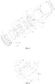
FIG. 1 is a perspective view of an atomization assembly according to a preferred embodiment of the present disclosure. -
FIG. 2 is a sectional view of the atomization assembly shown inFIG. 1 . -
FIG. 3 is an exploded view of the atomization assembly shown inFIG. 1 . -
FIG. 4 is a perspective view showing a scenario in which a porous body is matched with a heating element for the atomization assembly shown inFIG. 1 . -
FIG. 5 is a perspective view of a blocking seat according to another embodiment of the present disclosure. -
FIG. 6 is a perspective view of a blocking seat according to another embodiment of the present disclosure. - For a better understanding, the present disclosure is described below in further detail in conjunction with accompanying drawings and specific embodiments.
- With reference to
FIG. 1 to FIG. 4 , the present disclosure provides an atomization assembly, including an e-liquid reservoir 1, aporous body 2, aheating element 3, anelectrode 4 and amagnetic element 5, wherein the e-liquid reservoir 1 includes an aerosol channel a, an e-liquid storage cavity b used for storing an e-liquid, and an air inlet channel communicated with outside of the atomization assembly. The e-liquid reservoir 1 includes ane-liquid storage sleeve 11, a sealingseat 12, afixing seat 13 and a blockingseat 14; thee-liquid storage sleeve 11 includes asleeve body portion 111 and atube body portion 112, thetube body portion 112 is accommodated in thesleeve body portion 111, an inner space of thetube body portion 112 forms the aerosol channel a, the e-liquid storage cavity b is formed between thetube body portion 112 and thesleeve body portion 111, and the e-liquid storage cavity b is arranged surrounding the aerosol channel a. - The sealing
seat 12 is accommodated in thee-liquid storage sleeve 11 and is sleeved on theporous body 2, and a peripheral surface of the sealingseat 12 presses against thee-liquid storage sleeve 11 elastically to seal the cavity opening of the e-liquid storage cavity b. The sealingseat 12 includes afirst perforation 121, asecond perforation 122 and athird perforation 123; both of thefirst perforation 121 and thethird perforation 123 are communicated with the e-liquid storage cavity b. Thesecond perforation 122 is located between thefirst perforation 121 and thethird perforation 123 and is spaced from thefirst perforation 121 and thethird perforation 123. A first end of thetube body portion 112 is connected to thesleeve body portion 111, and a second end of thetube body portion 112 is inserted into thesecond perforation 122. - The
fixing seat 13 is installed on an end part of thee-liquid storage sleeve 11 and located on an end surface of thee-liquid storage sleeve 11. Thefixing seat 13 and thee-liquid storage sleeve 11 are in interference fit or buckled connection, etc., and no concrete limitation is made here. In the present embodiment, thefixing seat 13 and thee-liquid storage sleeve 11 are in interference fit, a peripheral surface of thefixing seat 13 is further sleeved with asealing ring 6, and thesealing ring 6 presses against an inner wall surface of thee-liquid storage sleeve 11 elastically. The fixingseat 13 presses against the sealingseat 12, thefixing seat 13 includes the firste-liquid holding tank 131, and the firste-liquid holding tank 131 faces theporous body 2, thereby being able to collect the e-liquid leaking from theporous body 2 or a condensed e-liquid formed on the aerosol channel a. - The
fixing seat 13 includes anair inlet 132, theair inlet 132 passes through a bottom wall of the firste-liquid holding tank 131, and an air exit of theair inlet 132 is higher than the bottom wall of the firste-liquid holding tank 131, thereby being able to prevent the e-liquid inside the firste-liquid holding tank 131 flowing out from theair inlet 132 and better avoiding leakage of e-liquid. The blockingseat 14 is located between theporous body 2 and thefixing seat 13 and presses against theporous body 2, so that theporous body 2 is more firmly fixed. The blockingseat 14 includes anair groove 141, a bottom wall of theair groove 141 includes an air through-hole 142, and the air through-hole 142 is communicated with the firste-liquid holding tank 131 and theair groove 141. In the present embodiment, the blockingseat 14 is made of a silicone material, which can better seal theporous body 2. Theair inlet 132 serves as the air inlet channel. It is understandable that the structure of the e-liquid reservoir 1 may be arranged as needed, as long as it can be configured for storing an e-liquid, and no concrete limitation is made for the structure here. - The
porous body 2 is used for adsorbing the e-liquid in the e-liquid storage cavity b, theporous body 2 includes ane-liquid guide wall 21 and anair inlet wall 22, and thee-liquid guide wall 21 is configured for guiding the e-liquid in the e-liquid storage cavity b to theheating element 3 to atomize. The air in the air inlet channel can flow into the e-liquid storage cavity b through theair inlet wall 22, which means theporous body 2 does not require an extra air hole for air admission and only needs the micropores of the material of theair inlet wall 22 itself for air admission. When the atmospheric pressure inside the e-liquid storage cavity b is smaller than the atmospheric pressure outside the atomization assembly, the air outside the atomization assembly passes through the air inlet channel and enters the e-liquid storage cavity b from theair inlet wall 22, so that the atmospheric pressure inside the e-liquid storage cavity b is equal to or tends to be equal to the atmospheric pressure outside the atomization assembly. - It is understandable that the speed of the air to flow into the e-liquid storage cavity b is determined by the size of the micropore of the material of the
air inlet wall 22 itself and the difference in atmospheric pressure between inside of the e-liquid storage cavity b and outside of the atomization assembly. The blockingseat 14 is configured for guiding an airflow entering from theair inlet 132 onto thee-liquid atomization surface 21. Arrows shown inFIG. 2 indicate the flow direction of air during the operation of the atomization assembly. - The
porous body 2 may be a porous ceramic body or a fibrous body, etc., and no concrete limitation is made here. In the present embodiment, theporous body 2 includes afirst recess 23, asecond recess 24 and a blockingwall 25 located between thefirst recess 23 and thesecond recess 24; thefirst recess 23 corresponds to thefirst perforation 121 in position, and thesecond recess 24 corresponds to thethird perforation 123 in position. Both of thefirst recess 23 and thesecond recess 24 are communicated with the e-liquid storage cavity b; an inner wall surface of thefirst recess 23 and an inner wall surface of thesecond recess 24 form an e-liquid contact surface p1, and theporous body 2 adsorbs the e-liquid in the e-liquid storage cavity b by means of the e-liquid contact surface p1. - It is understandable that the e-liquid contact surface p1 refers to a surface of the
porous body 2 which is configured for absorbing the e-liquid in the e-liquid storage cavity b by contacting the e-liquid flowing downward from the e-liquid storage cavity b; the e-liquid in the e-liquid storage cavity b enters theporous body 2 through this surface; the e-liquid contact surface p1 may be constructed by a plane or a curved surface, and there may be one or more planes or curved surfaces. - A bottom wall of the
first recess 23 forms thee-liquid guide wall 21 of which a bottom surface forms the e-liquid atomization surface P2, and theporous body 3 provides, through the e-liquid atomization surface P2, the absorbed e-liquid to theheating element 3 to atomize. A bottom wall of thesecond recess 24 forms anair inlet wall 22 of which a bottom surface forms the air inlet surface p3, and the air inlet surface p3 is used for allowing air to flow into theporous body 2 and flow into the e-liquid storage cavity b by means of theporous body 2; the distance between the air inlet surface p3 and the e-liquid contact surface p1 is smaller than the distance between the e-liquid atomization surface p2 and the e-liquid contact surface p1, which means theair inlet wall 22 has a smaller thickness than thee-liquid guide wall 21; therefore, external air may flow into the e-liquid storage cavity b relatively smoothly. - Specifically, a surface of the
porous body 2 away from the e-liquid storage cavity b is a bottom surface p4 for theheating element 3 to attach onto, both of the e-liquid atomization surface p2 and the air inlet surface p3 are located within the bottom surface p4, and the bottom surface p4 is a plane, that is to say, the e-liquid atomization surface p2 and the air inlet surface p3 are located within one same plane, which facilitates manufacturing. It is understandable that theheating element 3 may be completely located within the e-liquid atomization surface p2, also may be extended onto the air inlet surface p3, and no concrete limitation is made here. The blockingwall 25 includes anair hole 26 which is communicated with the aerosol channel a, thee-liquid guide wall 21 and theair inlet wall 22 are located at two opposite sides of the position of theair hole 26 respectively, making the overall ventilation relatively smoother. Since the bottom wall of thefirst recess 23 forms thee-liquid guide wall 21, a side wall of thefirst recess 23 can also provide e-liquid for thee-liquid guide wall 21, thereby better ensuring sufficient supply of e-liquid. - Between the bottom wall of the
air groove 141 and theporous body 2 is formed an atomization channel c which is configured for allowing an aerosol formed by atomization of e-liquid to flow through; the atomization channel c is communicated with theair inlet 132, theair hole 26 and the aerosol channel a, so as to discharge the aerosol formed by atomization of e-liquid to the outside of the atomization assembly. Both of the e-liquid atomization surface p2 and the air inlet surface p3 are located inside the atomization channel c, which not only facilitates the discharge of aerosol to the outside of the atomization assembly, but also minimizes, during the process of smoking, the difference in atmospheric pressure between insides of the e-liquid storage cavity b and the atomization channel c, so that the e-liquid may easily flow onto the e-liquid atomization surface p2. During smoking, external air flows into the atomization channel c from theair inlet 132, and then, together with the aerosol inside the atomization channel c, passes through theair hole 26 and the aerosol channel a to be discharged to the outside of the atomization assembly. - At least part of the
heating element 3 is in contact with thee-liquid guide wall 21 so as to atomize the e-liquid on thee-liquid guide wall 21, which means theheating element 3 may be embedded into thee-liquid guide wall 21 and partially extended onto the e-liquid atomization surface p2, or theheating element 3 is an electric heating circuit printed onto the e-liquid atomization surface p2, or one end of theheating element 3 is located on the e-liquid atomization surface p2 and the other end is located on the air inlet surface p3. Therefore, theheating element 3 is completely or at least in part in contact with thee-liquid guide wall 21, and no concrete limitation is made here. - In the present embodiment, the
heating element 3 includes aheating section 31, an extendingsection 32, a firstelectrical connection portion 33 and a secondelectrical connection portion 34; theheating section 31 is attached onto thee-liquid guide wall 21 and is connected to the firstelectrical connection portion 33; theheating section 31 is located within the e-liquid atomization surface p2, which means theheating section 31 is arranged extending on the e-liquid atomization surface p2, thereby being able to fully atomize the e-liquid on the e-liquid atomization surface p2. A first end of the extendingsection 32 is connected to a first end of theheating section 31, the firstelectrical connection portion 33 is connected to a second end of theheating section 31, and a second end of the extendingsection 32 is connected to the secondelectrical connection portion 34; the extendingsection 32 has a greater cross-sectional area than theheating section 31. The extendingsection 32 is arranged deviating from the e-liquid atomization surface p2 and is attached onto theporous body 2, thereby being able to avoid, during operation, dry burning occurring at an area of theporous body 2 where the extendingsection 32 is located. - Preferably, at least part of the extending
section 32 is attached onto the air inlet surface p3, and a contact area between the extendingsection 32 and theporous body 2 is greater than a contact area between theheating section 31 and theporous body 2, thereby being able to reduce the likelihood of the e-liquid dropping from the extendingsection 32. It is understandable that theheating element 3 may be a metal wire, also may be an electric heating circuit printed onto theporous body 2, and no concrete limitation is made here, as long as it can be electrified to generate heat. In addition, in some embodiments, theheating element 3 is completely located on the e-liquid atomization surface p2, and theporous body 2 may not be provided with thefirst recess 23. Of course, theporous body 2 may not be provided with thesecond recess 24 either, as long as the distance between the air inlet surface p3 and the e-liquid contact surface p1 is smaller than the distance between the e-liquid atomization surface p2 and the e-liquid contact surface p1. - The
electrode 4 is fixed on the fixingseat 13; one end of theelectrode 4 presses against theheating element 3, and the other end of theelectrode 4 is electrically connected to the battery assembly. In the present embodiment, there are twoelectrodes 4; one electrode presses against the firstelectrical connection portion 33 and the other electrode presses against the secondelectrical connection portion 24. Themagnetic element 5 is fixed on the fixingseat 13 for magnetic connection with the battery assembly, so that the connection is more secure. - The present disclosure further provides an electronic cigarette, including an atomization assembly and a battery assembly configured for supplying power to the atomization assembly, wherein the atomization assembly is the one described above, having the same technical effect. The battery assembly is of an available technology, and no concrete limitation is made for the structure here.
- Due to the fact that the
porous body 2 includes the e-liquid atomization surface p2 and the air inlet surface p3 that are separately arranged, the distance between the air inlet surface p3 and the e-liquid contact surface p1 is smaller than the distance between the e-liquid atomization surface p2 and the e-liquid contact surface p1, and air can flow into the e-liquid storage cavity b through the air inlet surface p3, thus, the atmospheric pressure inside the e-liquid storage cavity b is equal to or not so different from the atmospheric pressure outside the atomization assembly, the e-liquid inside the e-liquid storage cavity b can smoothly flow onto thee-liquid guide wall 21, with sufficient supply of e-liquid. When theheating element 3 generates heat, thee-liquid guide wall 21 can provide sufficient e-liquid, and therefore burnt smell can be avoided. - With reference to
FIG. 5 , the present embodiment is similar to Embodiment 1 in structure, with the main difference lying in that the blockingseat 14 includes a seconde-liquid holding tank 143, of which a tank opening is arranged facing theporous body 2. Specifically, the tank opening of the seconde-liquid holding tank 143 is arranged facing theair inlet wall 22, to better collect the e-liquid dropping or leaking from theair inlet wall 22. - With reference to
FIG. 6 , the present embodiment is similar to Embodiment 1 in structure, with the main difference lying in that the blockingseat 14 includes a seconde-liquid holding tank 143, of which a tank opening is arranged facing theporous body 2. Specifically, the tank opening of the seconde-liquid holding tank 143 is arranged facing the entire bottom surface of theporous body 2, to better collect the e-liquid dropping or leaking from theporous body 2. In the present embodiment, an air inlet groove is located on a side wall of the blockingseat 14. According to the present embodiment, the seconde-liquid holding tank 143 has a larger space and can contain more e-liquid. - It is to be noted that the description of the present disclosure and the drawings just list some preferred embodiments of the present disclosure and are not limited to the embodiments described herein. Further, for the ordinary staff in this field, improvements or variations may be made according to the above description, and these improvements or variations are intended to be covered within the scope of protection of the claims appended hereinafter.
Claims (13)
- An atomization assembly, comprising an e-liquid reservoir, a porous body, and a heating element, wherein the e-liquid reservoir comprises an e-liquid storage cavity used for storing an e-liquid, the porous body is used for adsorbing the e-liquid in the e-liquid storage cavity; the porous body comprises an e-liquid contact surface, an e-liquid atomization surface and an air inlet surface; the porous body adsorbs the e-liquid in the e-liquid storage cavity by means of the e-liquid contact surface; the air inlet surface is used for allowing air to flow into the porous body and flow into the e-liquid storage cavity by means of the porous body; the distance between the air inlet surface and the e-liquid contact surface is smaller than the distance between the e-liquid atomization surface and the e-liquid contact surface, and at least part of the heating element is combined onto the e-liquid atomization surface so as to atomize the e-liquid on the e-liquid atomization surface.
- The atomization assembly according to claim 1, wherein the heating element comprises a heating section, which is arranged extending within the e-liquid atomization surface.
- The atomization assembly according to claim 2, wherein the heating element further comprises an extending section, a first electrical connection portion and a second electrical connection portion, a first end of the extending section is connected to a first end of the heating section, a second end of the extending section is connected to the second electrical connection portion, and the first electrical connection portion is connected to a second end of the heating section.
- The atomization assembly according to claim 3, wherein the extending section has a greater cross-sectional area than the heating section.
- The atomization assembly according to claim 3, wherein the e-liquid atomization surface and the air inlet surface are located within one same plane, at least part of the extending section is attached onto the air inlet surface, a contact area between the extending section and the porous body is greater than a contact area between the heating section and the porous body.
- The atomization assembly according to any one of claims 1 to 5, wherein the porous body comprises a first recess and a second recess, both of the first recess and the second recess are communicated with the e-liquid storage cavity, a bottom wall of the first recess forms an e-liquid guide wall of which a bottom surface forms the e-liquid atomization surface, and a bottom wall of the second recess forms an air inlet wall of which a bottom surface forms the air inlet surface.
- The atomization assembly according to claim 6, wherein the e-liquid reservoir further comprises an aerosol channel, the porous body further comprises a blocking wall located between the first recess and the second recess, the blocking wall comprises an air hole which is communicated with the aerosol channel, the e-liquid guide wall and the air inlet wall are located at two opposite sides of the position of the air hole respectively.
- The atomization assembly according to any one of claims 1 to 5, wherein the e-liquid reservoir further comprises a first e-liquid holding tank, which is configured for storing a condensed or leaking e-liquid.
- The atomization assembly according to claim 8, wherein the e-liquid reservoir comprises an e-liquid storage sleeve, a sealing seat and a fixing seat; the e-liquid storage sleeve comprises the e-liquid storage cavity; the sealing seat is accommodated in the e-liquid storage sleeve and is sleeved on the porous body, and the sealing seat seals the cavity opening of the e-liquid storage cavity; the fixing seat is installed on an end part of the e-liquid storage sleeve, the fixing seat presses against the sealing seat, and the fixing seat comprises the first e-liquid holding tank.
- The atomization assembly according to claim 9, wherein the e-liquid reservoir further comprises a blocking seat, the fixing seat comprises an air inlet, the blocking seat is located between the porous body and the fixing seat, and the blocking seat is configured for guiding an airflow entering from the air inlet onto the e-liquid atomization surface.
- The atomization assembly according to claim 10, wherein the blocking seat comprises a second e-liquid holding tank, of which a tank opening is arranged facing the porous body.
- The atomization assembly according to any one of claims 1 to 5, wherein the atomization assembly comprises an atomization channel, which is configured for allowing an aerosol formed by atomization of e-liquid to flow through to be discharged to the outside of the atomization assembly; and both of the e-liquid atomization surface and the air inlet surface are exposed into the atomization channel.
- An electronic cigarette, comprising an atomization assembly and a battery assembly configured for supplying power to the atomization assembly, wherein the atomization assembly is the one described according to any one of claims 1 to 12.
Applications Claiming Priority (2)
| Application Number | Priority Date | Filing Date | Title |
|---|---|---|---|
| CN201922061877.2U CN211482973U (en) | 2019-11-26 | 2019-11-26 | Atomizing components and electronic cigarettes |
| PCT/CN2020/131870 WO2021104390A1 (en) | 2019-11-26 | 2020-11-26 | Atomization assembly and electronic cigarette |
Publications (2)
| Publication Number | Publication Date |
|---|---|
| EP4066660A1 true EP4066660A1 (en) | 2022-10-05 |
| EP4066660A4 EP4066660A4 (en) | 2022-12-28 |
Family
ID=72411407
Family Applications (1)
| Application Number | Title | Priority Date | Filing Date |
|---|---|---|---|
| EP20894540.2A Withdrawn EP4066660A4 (en) | 2019-11-26 | 2020-11-26 | ATOMIZATION SET AND ELECTRONIC CIGARETTE |
Country Status (4)
| Country | Link |
|---|---|
| US (1) | US20230000154A1 (en) |
| EP (1) | EP4066660A4 (en) |
| CN (1) | CN211482973U (en) |
| WO (1) | WO2021104390A1 (en) |
Families Citing this family (9)
| Publication number | Priority date | Publication date | Assignee | Title |
|---|---|---|---|---|
| CN211482973U (en) * | 2019-11-26 | 2020-09-15 | 深圳市合元科技有限公司 | Atomizing components and electronic cigarettes |
| WO2022061603A1 (en) * | 2020-09-23 | 2022-03-31 | 深圳麦克韦尔科技有限公司 | Vaporization core, vaporizer, and electronic vaporization apparatus |
| CN112120291B (en) * | 2020-09-23 | 2025-03-14 | 深圳麦克韦尔科技有限公司 | Atomizer core, atomizer and electronic atomization device |
| CN112316261A (en) * | 2020-10-27 | 2021-02-05 | 深圳市康泓威科技有限公司 | Nebulizer with integrated nebulizer assembly |
| CN214414097U (en) * | 2020-11-13 | 2021-10-19 | 常州市派腾电子技术服务有限公司 | Air intake liquid blocking structure, atomizer and aerosol generating device |
| CN112790434A (en) * | 2021-01-22 | 2021-05-14 | 深圳麦克韦尔科技有限公司 | Electronic atomizing device, atomizer and atomizing assembly therefor |
| CN215958369U (en) * | 2021-05-20 | 2022-03-08 | 深圳市合元科技有限公司 | Atomizer and aerosol-generating device |
| CN216293045U (en) * | 2021-08-13 | 2022-04-15 | 深圳麦克韦尔科技有限公司 | Electronic atomization device and atomizer and atomization assembly thereof |
| CA212411S (en) * | 2021-11-03 | 2024-03-04 | Shenzhen Relx Tech Co Ltd | Conductive Pin of a Pod for an Electronic Cigarette |
Family Cites Families (15)
| Publication number | Priority date | Publication date | Assignee | Title |
|---|---|---|---|---|
| EP2460422A1 (en) * | 2010-12-03 | 2012-06-06 | Philip Morris Products S.A. | An aerosol generating system with provention of condensate leakage |
| CN103960781A (en) * | 2013-09-29 | 2014-08-06 | 深圳市麦克韦尔科技有限公司 | Electronic cigarette |
| KR102721939B1 (en) * | 2013-12-23 | 2024-10-25 | 쥴 랩스, 인크. | Vaporization device systems and methods |
| EP3685687B1 (en) * | 2015-10-21 | 2023-06-14 | Shenzhen Smoore Technology Limited | Electronic cigarette |
| CN106037009B (en) * | 2016-05-27 | 2018-10-26 | 深圳瀚星翔科技有限公司 | Electrical steam device |
| CN109259318A (en) * | 2017-07-17 | 2019-01-25 | 湖南中烟工业有限责任公司 | A kind of electronic smoke atomizer |
| CA3096851A1 (en) * | 2018-04-10 | 2019-10-17 | Iconic Ventures, Inc. | Vaporizable substance storage device |
| WO2019206985A1 (en) * | 2018-04-26 | 2019-10-31 | Philip Morris Products S.A. | Heater assembly having heater element isolated from liquid supply |
| CN209403574U (en) * | 2018-09-05 | 2019-09-20 | 深圳麦克韦尔科技有限公司 | Atomising device and electronic cigarette |
| CN209436269U (en) * | 2018-12-26 | 2019-09-27 | 常州市派腾电子技术服务有限公司 | Cartridges and Electronic Cigarettes |
| CN209498584U (en) * | 2018-12-26 | 2019-10-18 | 深圳市合元科技有限公司 | Vape atomizer and electronic cigarette |
| EP3964090A4 (en) * | 2019-05-22 | 2022-04-27 | Shenzhen Smoore Technology Limited | ELECTRONIC ATOMIZER DEVICE AND ASSOCIATED ATOMIZER, SEALING STRUCTURE AND ATOMIZER ASSEMBLY METHOD |
| EP3984389A4 (en) * | 2019-06-14 | 2022-07-20 | Shenzhen Smoore Technology Limited | ELECTRONIC ATOMIZER DEVICE, AND ASSOCIATED ATOMIZER AND HEATER ASSEMBLY |
| CN110338466B (en) * | 2019-07-19 | 2024-07-12 | 深圳麦克韦尔科技有限公司 | Electronic atomization device, atomizer thereof, heating component and porous ceramic body |
| CN211482973U (en) * | 2019-11-26 | 2020-09-15 | 深圳市合元科技有限公司 | Atomizing components and electronic cigarettes |
-
2019
- 2019-11-26 CN CN201922061877.2U patent/CN211482973U/en active Active
-
2020
- 2020-11-26 US US17/756,418 patent/US20230000154A1/en not_active Abandoned
- 2020-11-26 WO PCT/CN2020/131870 patent/WO2021104390A1/en not_active Ceased
- 2020-11-26 EP EP20894540.2A patent/EP4066660A4/en not_active Withdrawn
Also Published As
| Publication number | Publication date |
|---|---|
| EP4066660A4 (en) | 2022-12-28 |
| CN211482973U (en) | 2020-09-15 |
| US20230000154A1 (en) | 2023-01-05 |
| WO2021104390A1 (en) | 2021-06-03 |
Similar Documents
| Publication | Publication Date | Title |
|---|---|---|
| US20230000154A1 (en) | Atomization assembly and electronic cigarette | |
| US20260060302A1 (en) | Atomizing core, atomizer and electronic atomizing device | |
| CN211910526U (en) | Atomizing components and electronic cigarettes | |
| US20240023609A1 (en) | Electronic atomization device | |
| US10986868B2 (en) | Electronic atomizing device with a liquid guiding effect and atomizer | |
| EP3850963B1 (en) | Electronic atomization device and atomizer | |
| CN114376273B (en) | Atomizing structure, atomizer and aerosol generating device | |
| CN112931955A (en) | Atomizer and electronic atomization device | |
| EP4268633B1 (en) | Atomizer and electronic atomization device | |
| CN112493550A (en) | Atomizer and electronic atomization device thereof | |
| WO2021184943A1 (en) | Sensor sealing element and electronic cigarette | |
| CN114259091A (en) | Atomization structure, atomizer and aerosol generating device | |
| CN116035278A (en) | Atomization components, atomizers and electronic atomization devices | |
| CN216088844U (en) | Electronic atomization device and atomizer and atomization core thereof | |
| CN115844059A (en) | Electronic heating atomization unit and device with ventilation micro-groove structure | |
| US20240000150A1 (en) | Vaporization device and electronic cigarette having same | |
| CN112931963A (en) | Atomizer and electronic atomization device | |
| CN218551330U (en) | Electronic atomization device and atomizer thereof | |
| CN217771425U (en) | Atomizer and electronic atomization device | |
| CN116584703A (en) | An aerosol generating device | |
| CN215013592U (en) | Atomizer and electronic atomization device | |
| CN110973706A (en) | Electronic atomization device | |
| CN215381437U (en) | Seal assembly, atomizer and electronic atomization device | |
| CN214431802U (en) | Electronic atomization device and atomizer thereof | |
| US20240074502A1 (en) | Electronic vaporization device and vaporizer thereof |
Legal Events
| Date | Code | Title | Description |
|---|---|---|---|
| STAA | Information on the status of an ep patent application or granted ep patent |
Free format text: STATUS: THE INTERNATIONAL PUBLICATION HAS BEEN MADE |
|
| PUAI | Public reference made under article 153(3) epc to a published international application that has entered the european phase |
Free format text: ORIGINAL CODE: 0009012 |
|
| STAA | Information on the status of an ep patent application or granted ep patent |
Free format text: STATUS: REQUEST FOR EXAMINATION WAS MADE |
|
| 17P | Request for examination filed |
Effective date: 20220525 |
|
| AK | Designated contracting states |
Kind code of ref document: A1 Designated state(s): AL AT BE BG CH CY CZ DE DK EE ES FI FR GB GR HR HU IE IS IT LI LT LU LV MC MK MT NL NO PL PT RO RS SE SI SK SM TR |
|
| STAA | Information on the status of an ep patent application or granted ep patent |
Free format text: STATUS: EXAMINATION IS IN PROGRESS |
|
| A4 | Supplementary search report drawn up and despatched |
Effective date: 20221124 |
|
| RIC1 | Information provided on ipc code assigned before grant |
Ipc: A24F 40/46 20200101ALI20221118BHEP Ipc: A24F 40/42 20200101ALI20221118BHEP Ipc: A24F 40/40 20200101AFI20221118BHEP |
|
| 17Q | First examination report despatched |
Effective date: 20221206 |
|
| DAV | Request for validation of the european patent (deleted) | ||
| DAX | Request for extension of the european patent (deleted) | ||
| STAA | Information on the status of an ep patent application or granted ep patent |
Free format text: STATUS: THE APPLICATION IS DEEMED TO BE WITHDRAWN |
|
| 18D | Application deemed to be withdrawn |
Effective date: 20240911 |