EP4066332B1 - Electric plug for connection to a vehicle camera, as well as arrangement - Google Patents
Electric plug for connection to a vehicle camera, as well as arrangement Download PDFInfo
- Publication number
- EP4066332B1 EP4066332B1 EP20812307.5A EP20812307A EP4066332B1 EP 4066332 B1 EP4066332 B1 EP 4066332B1 EP 20812307 A EP20812307 A EP 20812307A EP 4066332 B1 EP4066332 B1 EP 4066332B1
- Authority
- EP
- European Patent Office
- Prior art keywords
- plug
- vehicle camera
- electric plug
- electric
- cover collar
- Prior art date
- Legal status (The legal status is an assumption and is not a legal conclusion. Google has not performed a legal analysis and makes no representation as to the accuracy of the status listed.)
- Active
Links
Images


Classifications
-
- H—ELECTRICITY
- H01—ELECTRIC ELEMENTS
- H01R—ELECTRICALLY-CONDUCTIVE CONNECTIONS; STRUCTURAL ASSOCIATIONS OF A PLURALITY OF MUTUALLY-INSULATED ELECTRICAL CONNECTING ELEMENTS; COUPLING DEVICES; CURRENT COLLECTORS
- H01R13/00—Details of coupling devices of the kinds covered by groups H01R12/70 or H01R24/00 - H01R33/00
- H01R13/648—Protective earth or shield arrangements on coupling devices, e.g. anti-static shielding
- H01R13/658—High frequency shielding arrangements, e.g. against EMI [Electro-Magnetic Interference] or EMP [Electro-Magnetic Pulse]
- H01R13/6581—Shield structure
- H01R13/6582—Shield structure with resilient means for engaging mating connector
-
- H—ELECTRICITY
- H01—ELECTRIC ELEMENTS
- H01R—ELECTRICALLY-CONDUCTIVE CONNECTIONS; STRUCTURAL ASSOCIATIONS OF A PLURALITY OF MUTUALLY-INSULATED ELECTRICAL CONNECTING ELEMENTS; COUPLING DEVICES; CURRENT COLLECTORS
- H01R13/00—Details of coupling devices of the kinds covered by groups H01R12/70 or H01R24/00 - H01R33/00
- H01R13/648—Protective earth or shield arrangements on coupling devices, e.g. anti-static shielding
- H01R13/658—High frequency shielding arrangements, e.g. against EMI [Electro-Magnetic Interference] or EMP [Electro-Magnetic Pulse]
- H01R13/6591—Specific features or arrangements of connection of shield to conductive members
- H01R13/6597—Specific features or arrangements of connection of shield to conductive members the conductive member being a contact of the connector
-
- H—ELECTRICITY
- H01—ELECTRIC ELEMENTS
- H01R—ELECTRICALLY-CONDUCTIVE CONNECTIONS; STRUCTURAL ASSOCIATIONS OF A PLURALITY OF MUTUALLY-INSULATED ELECTRICAL CONNECTING ELEMENTS; COUPLING DEVICES; CURRENT COLLECTORS
- H01R13/00—Details of coupling devices of the kinds covered by groups H01R12/70 or H01R24/00 - H01R33/00
- H01R13/02—Contact members
- H01R13/22—Contacts for co-operating by abutting
-
- H—ELECTRICITY
- H01—ELECTRIC ELEMENTS
- H01R—ELECTRICALLY-CONDUCTIVE CONNECTIONS; STRUCTURAL ASSOCIATIONS OF A PLURALITY OF MUTUALLY-INSULATED ELECTRICAL CONNECTING ELEMENTS; COUPLING DEVICES; CURRENT COLLECTORS
- H01R2201/00—Connectors or connections adapted for particular applications
- H01R2201/26—Connectors or connections adapted for particular applications for vehicles
Definitions
- the invention relates to an electric plug for connection to a vehicle camera.
- a further aspect of the invention relates to an arrangement comprising a vehicle camera and an electric plug.
- Vehicle cameras are known in manifold designs. Commonly they are of compact structure and can be arranged so that they capture the environment of the motor vehicle. Vehicle cameras are commonly connected with electric plugs so that an exchange of signals is facilitated. Such electric plugs commonly are to be connected non-destructively releasably with the vehicle camera. For instance such designs are known from the US 10,071,696 B2 , US2017201661 , US2006189183 and the JP 2007022364 A . Such connections, however, with regard to the electric shielding have to comply with high safety requirements. In the known embodiments in this connection very complex solutions are envisaged. These are only partly suitable, on the one hand, relatively expensive, on the other hand.
- the electric plug for connecting to a vehicle camera comprises a plug head.
- the electric plug moreover comprises at least one electric signal contact and at least one ground contact that is separate therefrom.
- the electric signal contact and the ground contact are configured on the plug head.
- the plug head comprises a carrier block for the signal contact and the ground contact.
- the carrier block comprises a jacket wall, on which a cover collar projecting outwardly from the jacket wall and extending circumferentially on the jacket wall is arranged.
- An outwardly projecting shielding flap of the electric plug is configured to be integrally formed with the cover collar.
- the shielding flap is connected with an electrically conductive connecting element, which is connected with the cover collar and the mass contact.
- this shielding flap contacts the housing of the vehicle camera.
- this housing of the vehicle camera can be brought to ground potential.
- the shielding flap is reliably connected with the ground contact of the plug head, here, too, no undesired electric potentials can develop on the shielding flap.
- the carrier block is configured as cuboid.
- the cuboid comprising a front wall, on which the ground contact and the signal contact are arranged.
- the common plug and retention forces are thereby advantageously configured
- the plug head comprises a corresponding solid carrier block, on the one hand, the positioning of the named contacts can be achieved safely and reliably. On the other hand, thereby also a raised number of contacts thereon can be realized.
- the carrier block moreover is also a correspondingly stable body, which can also reliably receive and retain the cover collar.
- the shielding flap is arranged to project at an angle from the cover collar.
- this shielding flap is arranged to project freely outward and cantilevering.
- this design it is arranged in particular exposed, in order to allow for best possible direct contact with the housing of the vehicle camera upon plugging together.
- At least two separate shielding flaps are envisaged. These are arranged opposite in the circumferential direction around the longitudinal axis, which also simultaneously corresponds to the extension direction of the electric plug upon being plugged together with the vehicle camera. This means that these two shielding flaps are offset against each other by 180°.
- the shielding flap is configured resiliently on the cover collar. Thereby a certain movement elasticity is achieved. This is particularly advantageous in order to facilitate when being plugged together with the vehicle camera a certain movement and deformation and moreover then also a pre-stressed seat or a pre-stressed contact of the shielding flap on a wall of the vehicle housing. Thereby always a direct contacting of the shielding flap with the housing of the vehicle camera can be achieved.
- the cover collar relative to the front wall of the carrier block viewed in the direction of the longitudinal axis is offset towards the back and is arranged on the jacket wall.
- the position of the cover collar is adjusted to the position of the carrier block, if the carrier block is plugged into the vehicle camera.
- the position of the cover collar can be reached in such a way that a possible gap between the electric plug, in particular the carrier block, and the housing of the vehicle camera is directly covered.
- the cover collar is configured to extend fully closed circumferentially on the jacket wall.
- a particularly high stability of the cover collar is achieved, on the other hand, in particularly advantageous manner a possible gap between the electric plug, in particular the carrier block, and a housing of the vehicle camera can be covered fully circumferentially.
- the cover collar and the at least one shielding flap is configured to be made from electrically conductive material, in particular from metal.
- the electromagnetic shielding, on the one hand, and the contacting of the housing of the vehicle camera with electric ground potential is thereby possible in a particularly advantageous way.
- the shielding flap is configured to be uneven. In particular it is configured to be bent at least once.
- a simple mounting process can be achieved. This means that the plugging of the electric plug into the housing of the vehicle camera is facilitated without jamming.
- an undesired jamming or seizing during moving relative to the wall of this housing can be avoided.
- the connecting element is configured as L-shaped strip.
- the connecting element is designed to be as small as possible and an as short as possible connecting path between the cover collar and thus also the shielding flap, on the one hand, and the ground contact, on the other hand, is achieved.
- the plug head comprises a plug cap.
- the carrier block which is separate thereto, is preferably received. It projects outwardly through an opening of the plug cap in the direction of the longitudinal axis of the plug head.
- the carrier block is still protected at least at that end which faces away from the vehicle camera or the housing of the vehicle camera.
- the cover collar is configured as electric shielding collar.
- an electric shielding here a particularly advantageous embodiment both in terms of device as well as in terms of position is provided.
- a further aspect of the invention relates to an arrangement with a vehicle camera and an electric plug that is separate therefrom.
- the plug is configured according to the above-named aspect or an advantageous embodiment.
- the vehicle camera comprises a connector unit for connecting the electric plug.
- the connector unit is incorporated in a housing part of a housing of the vehicle camera.
- a single-piece design is created.
- the plug head in a state, in which it is plugged to the vehicle component, is introduced into the connector unit and the shielding flap contacts the inner side of a wall of the connector unit.
- the shielding flap contacts the inner side of a wall of the connector unit.
- the plug head in a state, in which it is plugged to the vehicle camera, is introduced into the connector unit.
- the carrier block of the electric plug extends into a passage opening in the housing part of the vehicle camera.
- a gap between the carrier block and a boundary wall bounding the passage opening is covered, in particular fully covered, by the cover collar.
- the at least one signal contact and the ground contact are preferably configured as plate-like contacts.
- Preferably five signal contacts are configured. In particular these are all configured on the front wall of the carrier block.
- Fig. 1 in a perspective view an electric plug 1 is shown.
- the electric plug 1 is envisaged for connecting to a vehicle camera.
- the electric plug 1 is a so-called "pig tail" plug.
- the electric plug 1 comprises a plug head 2.
- this plug head 2 ends a cable 3 of the electric plug 1.
- In this cable 3 are arranged several individual cables. These lead to individual electric contacts of the electric plug 1.
- the electric plug 1 in this connection comprises at least one electric signal contact 4.
- five signal contacts 4 are provided, wherein only one is equipped with the reference sign 4.
- the electric plug 1 has a ground contact 5.
- the signal contacts 4 and the ground contact 5 are configured in the embodiment as strips or plates.
- the plug head 2 has a longitudinal axis A.
- the signal contacts 4 and the ground contact 5 extend in a plate, which is oriented perpendicular to the longitudinal axis A.
- the signal contacts 4 and the ground contact 5 are arranged on a front wall 6 of a carrier block 7 of the plug head 2.
- the carrier block 7 is configured in the embodiment as cuboid. Additionally to this front wall 6 it comprises a jacket wall 8. This thus is configured multifaceted in the embodiment.
- a cover collar 9 is configured.
- the cover collar 9 is configured in circumferential direction of the longitudinal axis A in the jacket wall 8.
- the cover collar 9 is configured to be fully circumferentially closed.
- a first shielding flap 10 and a further shielding flap 11 ( Fig. 3 ), which is separate therefrom, is integrally formed.
- the two shielding flaps 10 and 11, which are here exemplary, are thus formed as a single piece with this cover collar 9.
- the shielding flaps 10 and 11 extend from an outer edge 12 of the cover collar 9 projecting outward away from the jacket wall 8. They are not arranged in one plane, in which the cover collar 9 is formed. Rather the shielding flaps 10 and 11 in comparison with the plane, in which the cover collar 9 extends, are oriented in slanted position.
- the shielding flaps 10 and 11 are configured to be cantilevered. They are oriented to project in the manner of wings.
- the shielding flaps 10 and 11 are configured to face away projecting from the signal contacts 4 and the ground contact 5.
- the shielding flaps 10 and 11 are designed to be plate-like. They are, however, in particular configured to be uneven. In particular they are configured to be bent at least once.
- the shielding flap 10 comprises a first flap part 10a.
- This first flap part 10a extends directly from the cover collar 9.
- a second flap part 10c is adjacent.
- the second flap part 10c in relation to the plane, in which the cover collar 9 extends has a smaller inclination than the first flap part 10a.
- the plug head 2, as this can also be recognized in Fig. 1 in addition to the carrier block 7 comprises a plug cap 13. This is configured to be pot-like or trough-like. In the direction of the longitudinal axis A the carrier block 7 in relation to the plug cap 13 extends outwardly. In this connection the carrier block 7 thus extends through an opening 14 of the plug cap 13.
- the cover collar 9 in relation to the front wall 6 is offset towards the back. This means that it is closer to the plug cap 13 than the front wall 6.
- the electric plug 1 comprises a jacket 15.
- the jacket 15 partly surrounds the jacket wall 8.
- the jacket 15 surrounds the jacket wall 8.
- the jacket 15 in circumferential direction of the longitudinal axis A surrounds the jacket wall 8 completely, however, viewed in the direction of the longitudinal axis A surrounds the jacket wall 8 only partly.
- a partial area of the jacket wall 8 between the cover collar 9 and a portion of the carrier block 7 extending in the plug cap 13 is covered by this jacket 15.
- the electric plug 1 comprises a connecting element 16.
- This connecting element 16 is electrically conductive. It connects the ground contact 5 with the cover collar 9.
- an electric connection between the ground contact 5 and the at least one shielding flap 10, in particular the here two shielding flaps 10 and 11, is configured.
- the cover collar 9 and the therewith integrally formed shielding flaps 10 and 11 is configured to be made from an electrically conductive material, in particular from metal.
- this connecting element 16 is configured to be L-shaped. It is in this connection a thin connecting strip. It extends in this connection with a leg of L-shape axially on the jacket wall 8 and with a further leg of L-shape up to the ground contact 5.
- the cover collar 9 is configured as electric cover collar.
- a connecting unit in particular a housing part of a housing of the vehicle camera, and the carrier block 7.
- both a mechanical covering is achieved and also due to the electric properties an electromagnetic shielding facilitated.
- an exiting or an entering of undesired electromagnetic radiation through this gap can be avoided.
- the arrangement 17 comprises the electric plug 1 shown in a simplified representation. It moreover comprises a vehicle camera 18, which is separate from the electric plug 1.
- the vehicle camera 18 comprises a housing 19. This housing 19 has a rear housing part 20 and a front housing part 21, which is separate therefrom. The two housing parts 20 and 21 are connected with each other. Thereby an interior 22 of the housing 19 is formed. In this interior 22 at least one circuit board 23 of the vehicle camera 18 is arranged. On same electronic components and electric contacts 24 are arranged. Moreover there an image sensor 25 is arranged.
- the vehicle camera 18 moreover comprises a lens arrangement 26. This is represented as single block for the sake of simplicity.
- the lens arrangement 26 is arranged on the second housing part 21. Light, which is incident from the outside upon the lens arrangement 26, due to the optical imaging property is directed at the image sensor 25.
- the vehicle camera 18 comprises a connector unit 27 for the electric plug 1. In the embodiment shown this is integrally formed with the rear housing part 20.
- the connector unit 27 according to its intended use is envisaged for plugging-in into the electric plug 1.
- the connector unit 27 comprises a receiving portion 28, into which the electric plug 1, in particular with its plug head 2, is introduced or inserted.
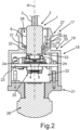
- Fig. 2 in this regard the fully plugged-in final state is shown.
- the shape and geometry of the plug head 2 are schematically shown in Fig. 2 and do not illustrate the exact geometry of the plug head 2 in Fig. 1 . It can be discerned that the shielding flap 10, which here is shown merely symbolically, directly contacts an inner side 29 of a wall 30 of the connector unit 27.
- this connector unit 27 and also the housing part 20 are connected to ground. Moreover it can also be seen that a gap 31 between the jacket wall 8 and an inner side 32 of the connector unit 27 and/or the housing part 20 is covered. This is achieved by the cover collar 9. In particular a complete covering of this gap 31 is achieved.
- the plug head 2 is introduced into the connector unit 27 and extends with the carrier hole 7 into a passage opening 33 in the housing part 20.
- Fig. 3 in a perspective view the arrangement 17 with sub-components of the vehicle camera 18 and sub-components of the plug 1 according to Fig. 1 are shown in more detail.
Landscapes
- Details Of Connecting Devices For Male And Female Coupling (AREA)
- Connector Housings Or Holding Contact Members (AREA)
- Studio Devices (AREA)
Description
- The invention relates to an electric plug for connection to a vehicle camera. A further aspect of the invention relates to an arrangement comprising a vehicle camera and an electric plug.
- Vehicle cameras are known in manifold designs. Commonly they are of compact structure and can be arranged so that they capture the environment of the motor vehicle. Vehicle cameras are commonly connected with electric plugs so that an exchange of signals is facilitated. Such electric plugs commonly are to be connected non-destructively releasably with the vehicle camera. For instance such designs are known from the
US 10,071,696 B2 US2017201661 ,US2006189183 and theJP 2007022364 A - It is the task of the present invention to provide an electric plug as well as an arrangement comprising such an electric plug and a vehicle camera, by which the electromagnetic shielding is improved.
- This task is solved by an electric plug according to
claim 1 and an arrangement according to claim 11. - The electric plug for connecting to a vehicle camera comprises a plug head. The electric plug moreover comprises at least one electric signal contact and at least one ground contact that is separate therefrom. The electric signal contact and the ground contact are configured on the plug head. The plug head comprises a carrier block for the signal contact and the ground contact. The carrier block comprises a jacket wall, on which a cover collar projecting outwardly from the jacket wall and extending circumferentially on the jacket wall is arranged.
- An outwardly projecting shielding flap of the electric plug is configured to be integrally formed with the cover collar. The shielding flap is connected with an electrically conductive connecting element, which is connected with the cover collar and the mass contact. By such a design of the electric plug an improved electromagnetic shielding is facilitated. In particular if the electric plug is connected with the vehicle camera, this cover collar, which is moreover also arranged at a specific location, namely on a jacket wall of a carrier block, is particularly suited, to cover gaps between the electric plug and the housing of the vehicle camera so that from these gaps the emitting of the electromagnetic field is at least reduced. Thereby the electromagnetic shielding is improved. In particularly advantageous way, moreover, the concept of the integrally formed shielding flaps at the same time a grounding of the housing of the vehicle camera is facilitated. This is because in the plugged together state between the electric plug and the vehicle camera this shielding flap contacts the housing of the vehicle camera. Thereby in a simple and still highly efficient way this housing of the vehicle camera can be brought to ground potential. Thus, also already upon plugging together of the plug with the vehicle camera the electric grounding of the housing is achieved safely and reliably. In that by the specifically arranged connecting element the shielding flap is reliably connected with the ground contact of the plug head, here, too, no undesired electric potentials can develop on the shielding flap. Furthermore, the carrier block is configured as cuboid. The cuboid comprising a front wall, on which the ground contact and the signal contact are arranged. By this shape design a very robust functional body is formed. The common plug and retention forces are thereby advantageously configured As the plug head comprises a corresponding solid carrier block, on the one hand, the positioning of the named contacts can be achieved safely and reliably. On the other hand, thereby also a raised number of contacts thereon can be realized. The carrier block moreover is also a correspondingly stable body, which can also reliably receive and retain the cover collar.
- Preferably, it is envisaged that the shielding flap is arranged to project at an angle from the cover collar. In particular this shielding flap is arranged to project freely outward and cantilevering. By this design it is arranged in particular exposed, in order to allow for best possible direct contact with the housing of the vehicle camera upon plugging together.
- Preferably, it is envisaged that at least two separate shielding flaps are envisaged. These are arranged opposite in the circumferential direction around the longitudinal axis, which also simultaneously corresponds to the extension direction of the electric plug upon being plugged together with the vehicle camera. This means that these two shielding flaps are offset against each other by 180°.
- In an advantageous embodiment it is envisaged that the shielding flap is configured resiliently on the cover collar. Thereby a certain movement elasticity is achieved. This is particularly advantageous in order to facilitate when being plugged together with the vehicle camera a certain movement and deformation and moreover then also a pre-stressed seat or a pre-stressed contact of the shielding flap on a wall of the vehicle housing. Thereby always a direct contacting of the shielding flap with the housing of the vehicle camera can be achieved.
- Advantageously it is envisaged that the cover collar relative to the front wall of the carrier block viewed in the direction of the longitudinal axis is offset towards the back and is arranged on the jacket wall. Thereby the position of the cover collar is adjusted to the position of the carrier block, if the carrier block is plugged into the vehicle camera. Thereby the position of the cover collar can be reached in such a way that a possible gap between the electric plug, in particular the carrier block, and the housing of the vehicle camera is directly covered.
- Preferably it is envisaged that the cover collar is configured to extend fully closed circumferentially on the jacket wall. On the one hand, thereby a particularly high stability of the cover collar is achieved, on the other hand, in particularly advantageous manner a possible gap between the electric plug, in particular the carrier block, and a housing of the vehicle camera can be covered fully circumferentially.
- Preferably it is envisaged that the cover collar and the at least one shielding flap is configured to be made from electrically conductive material, in particular from metal. The electromagnetic shielding, on the one hand, and the contacting of the housing of the vehicle camera with electric ground potential is thereby possible in a particularly advantageous way.
- Preferably it is envisaged that the shielding flap is configured to be uneven. In particular it is configured to be bent at least once. By such design a simple mounting process can be achieved. This means that the plugging of the electric plug into the housing of the vehicle camera is facilitated without jamming. By this design of the shielding flap an undesired jamming or seizing during moving relative to the wall of this housing can be avoided.
- Advantageously it is envisaged that the connecting element is configured as L-shaped strip. Thereby the connecting element is designed to be as small as possible and an as short as possible connecting path between the cover collar and thus also the shielding flap, on the one hand, and the ground contact, on the other hand, is achieved.
- In an advantageous embodiment it is envisaged that the plug head comprises a plug cap. In this plug cap the carrier block, which is separate thereto, is preferably received. It projects outwardly through an opening of the plug cap in the direction of the longitudinal axis of the plug head.
- Thereby the carrier block is still protected at least at that end which faces away from the vehicle camera or the housing of the vehicle camera.
- Preferably it is envisaged that the cover collar is configured as electric shielding collar. In particular with regard to an electric shielding here a particularly advantageous embodiment both in terms of device as well as in terms of position is provided.
- A further aspect of the invention relates to an arrangement with a vehicle camera and an electric plug that is separate therefrom. In particular the plug is configured according to the above-named aspect or an advantageous embodiment. The vehicle camera comprises a connector unit for connecting the electric plug.
- By such arrangement a simple plug-connecting between the electric plug and the vehicle camera is facilitated. At the same time thereby it is achieved that a gap between the electric plug, in particular a carrier block of the electric plug, and a housing of the vehicle, which belongs to the connector unit, is covered. Thereby at this very point, namely the interface between the electric plug and the vehicle component a particularly advantageous embodiment for an electromagnetic shielding is achieved. At the same time it is also facilitated that the connector unit and thus the housing part of the housing of the vehicle camera is securely brought to ground potential.
- Preferably it is envisaged that the connector unit is incorporated in a housing part of a housing of the vehicle camera. In this regard thus a single-piece design is created.
- Preferably it is envisaged that the plug head in a state, in which it is plugged to the vehicle component, is introduced into the connector unit and the shielding flap contacts the inner side of a wall of the connector unit. Thereby an electrically conductive connection between the wall and the ground contact of the electric plug is configured.
- Preferably it is envisaged that the plug head in a state, in which it is plugged to the vehicle camera, is introduced into the connector unit. In this state the carrier block of the electric plug extends into a passage opening in the housing part of the vehicle camera. By this passage opening in the housing part access to the interior of the housing of the vehicle camera is facilitated. A gap between the carrier block and a boundary wall bounding the passage opening is covered, in particular fully covered, by the cover collar.
- The at least one signal contact and the ground contact are preferably configured as plate-like contacts. Preferably five signal contacts are configured. In particular these are all configured on the front wall of the carrier block.
- Further features of the invention are apparent from the claims, the figures and the description of figures. The features and feature combinations mentioned above in the description as well as the features and feature combinations mentioned below in the description of figures and/or shown in the figures alone are usable not only in the respectively specified combination, but also in other combinations without departing from the scope of the invention. Thus, implementations are also to be considered as encompassed and disclosed by the invention, which are not explicitly shown in the figures and explained, but arise from and can be generated by the separated feature combinations from the explained implementations. Implementations and feature combinations are also to be considered as disclosed, which thus do not comprise all of the features of an originally formulated independent claim.
- Embodiments of the invention are explained in the following in further detail by reference to schematic drawings.
- These show in:
- Fig. 1
- a perspective representation of an embodiment of an electric plug;
- Fig. 2
- a schematic view of a vertical section through an embodiment of an arrangement according to the invention with a vehicle camera and an electric plug according to
Fig. 1 ; and - Fig. 3
- a perspective representation of sub-components of the plug according to
Fig. 1 and a vehicle camera. - In the figures identical elements or elements having identical functions are equipped with the same reference signs.
- In
Fig. 1 in a perspective view anelectric plug 1 is shown. According to its intended use, theelectric plug 1 is envisaged for connecting to a vehicle camera. Theelectric plug 1 is a so-called "pig tail" plug. Theelectric plug 1 comprises aplug head 2. In thisplug head 2 ends acable 3 of theelectric plug 1. In thiscable 3 are arranged several individual cables. These lead to individual electric contacts of theelectric plug 1. Theelectric plug 1 in this connection comprises at least oneelectric signal contact 4. In the embodiment fivesignal contacts 4 are provided, wherein only one is equipped with thereference sign 4. Moreover, theelectric plug 1 has aground contact 5. Thesignal contacts 4 and theground contact 5 are configured in the embodiment as strips or plates. Theplug head 2 has a longitudinal axis A. This corresponds to the vehicle camera, also in particular to the plug direction, during plugging together. As can be recognized, thesignal contacts 4 and theground contact 5 extend in a plate, which is oriented perpendicular to the longitudinal axis A. Thesignal contacts 4 and theground contact 5 are arranged on afront wall 6 of acarrier block 7 of theplug head 2. Thecarrier block 7 is configured in the embodiment as cuboid. Additionally to thisfront wall 6 it comprises ajacket wall 8. This thus is configured multifaceted in the embodiment. On this jacket wall 8 acover collar 9 is configured. Thecover collar 9 is configured in circumferential direction of the longitudinal axis A in thejacket wall 8. Thecover collar 9 is configured to be fully circumferentially closed. In relation to thejacket wall 8 viewed in a direction perpendicular to the longitudinal axis A it is outwardly projecting. On this cover collar 9 afirst shielding flap 10 and a further shielding flap 11 (Fig. 3 ), which is separate therefrom, is integrally formed. The two shieldingflaps 10 and 11, which are here exemplary, are thus formed as a single piece with thiscover collar 9. The shielding flaps 10 and 11 extend from anouter edge 12 of thecover collar 9 projecting outward away from thejacket wall 8. They are not arranged in one plane, in which thecover collar 9 is formed. Rather the shielding flaps 10 and 11 in comparison with the plane, in which thecover collar 9 extends, are oriented in slanted position. The shielding flaps 10 and 11 are configured to be cantilevered. They are oriented to project in the manner of wings. The shielding flaps 10 and 11 are configured to face away projecting from thesignal contacts 4 and theground contact 5. The shielding flaps 10 and 11 are designed to be plate-like. They are, however, in particular configured to be uneven. In particular they are configured to be bent at least once. - As can be in particular discerned in
Fig. 3 in this connection, the shieldingflap 10 comprises afirst flap part 10a. Thisfirst flap part 10a extends directly from thecover collar 9. To abending point 10b asecond flap part 10c is adjacent. As can be seen inFig. 3 , thesecond flap part 10c in relation to the plane, in which thecover collar 9 extends, has a smaller inclination than thefirst flap part 10a. - The
plug head 2, as this can also be recognized inFig. 1 , in addition to thecarrier block 7 comprises aplug cap 13. This is configured to be pot-like or trough-like. In the direction of the longitudinal axis A thecarrier block 7 in relation to theplug cap 13 extends outwardly. In this connection thecarrier block 7 thus extends through anopening 14 of theplug cap 13. - As can be recognized moreover, the
cover collar 9 in relation to thefront wall 6 is offset towards the back. This means that it is closer to theplug cap 13 than thefront wall 6. Moreover theelectric plug 1 comprises ajacket 15. Thejacket 15 partly surrounds thejacket wall 8. In particular thejacket 15 surrounds thejacket wall 8. In particular thejacket 15 in circumferential direction of the longitudinal axis A surrounds thejacket wall 8 completely, however, viewed in the direction of the longitudinal axis A surrounds thejacket wall 8 only partly. In particular a partial area of thejacket wall 8 between thecover collar 9 and a portion of thecarrier block 7 extending in theplug cap 13 is covered by thisjacket 15. - Moreover in
Fig. 1 it can be recognized that theelectric plug 1 comprises a connectingelement 16. This connectingelement 16 is electrically conductive. It connects theground contact 5 with thecover collar 9. In particular thus also an electric connection between theground contact 5 and the at least oneshielding flap 10, in particular the here two shieldingflaps 10 and 11, is configured. In particular thecover collar 9 and the therewith integrally formed shieldingflaps 10 and 11 is configured to be made from an electrically conductive material, in particular from metal. As can be seen inFig. 1 , this connectingelement 16 is configured to be L-shaped. It is in this connection a thin connecting strip. It extends in this connection with a leg of L-shape axially on thejacket wall 8 and with a further leg of L-shape up to theground contact 5. - In particular the
cover collar 9 is configured as electric cover collar. In the connected state with the vehicle camera it covers a gap between a connecting unit, in particular a housing part of a housing of the vehicle camera, and thecarrier block 7. Thereby both a mechanical covering is achieved and also due to the electric properties an electromagnetic shielding facilitated. Thereby an exiting or an entering of undesired electromagnetic radiation through this gap can be avoided. - In
Fig. 2 in a simplified vertical sectional view of anarrangement 17 is shown. Thearrangement 17 comprises theelectric plug 1 shown in a simplified representation. It moreover comprises avehicle camera 18, which is separate from theelectric plug 1. Thevehicle camera 18 comprises a housing 19. This housing 19 has a rear housing part 20 and afront housing part 21, which is separate therefrom. The twohousing parts 20 and 21 are connected with each other. Thereby an interior 22 of the housing 19 is formed. In this interior 22 at least onecircuit board 23 of thevehicle camera 18 is arranged. On same electronic components andelectric contacts 24 are arranged. Moreover there animage sensor 25 is arranged. Thevehicle camera 18 moreover comprises alens arrangement 26. This is represented as single block for the sake of simplicity. Thelens arrangement 26 is arranged on thesecond housing part 21. Light, which is incident from the outside upon thelens arrangement 26, due to the optical imaging property is directed at theimage sensor 25. - The
vehicle camera 18 comprises aconnector unit 27 for theelectric plug 1. In the embodiment shown this is integrally formed with the rear housing part 20. Theconnector unit 27 according to its intended use is envisaged for plugging-in into theelectric plug 1. For this purpose theconnector unit 27 comprises a receivingportion 28, into which theelectric plug 1, in particular with itsplug head 2, is introduced or inserted. InFig. 2 in this regard the fully plugged-in final state is shown. The shape and geometry of theplug head 2 are schematically shown inFig. 2 and do not illustrate the exact geometry of theplug head 2 inFig. 1 . It can be discerned that the shieldingflap 10, which here is shown merely symbolically, directly contacts aninner side 29 of awall 30 of theconnector unit 27. Thereby thisconnector unit 27 and also the housing part 20 are connected to ground. Moreover it can also be seen that agap 31 between thejacket wall 8 and aninner side 32 of theconnector unit 27 and/or the housing part 20 is covered. This is achieved by thecover collar 9. In particular a complete covering of thisgap 31 is achieved. - The
plug head 2 is introduced into theconnector unit 27 and extends with thecarrier hole 7 into apassage opening 33 in the housing part 20. - In
Fig. 3 in a perspective view thearrangement 17 with sub-components of thevehicle camera 18 and sub-components of theplug 1 according toFig. 1 are shown in more detail.
Claims (14)
- Electric plug (1) configured to be connected to a vehicle camera (18), comprising a plug head (2) and at least one electric signal contact (4) and at least one ground contact (5), which are configured on the plug head (2), wherein the plug head (2) comprises a carrier block (7) for the signal contact (4) and the ground contact (5), and the carrier block (7) comprises a jacket wall (8), on which a cover collar (9) projecting outwardly from the outer peripheral surface of the jacket wall (8) and extending circumferentially on the jacket wall (8) is arranged, wherein an outwardly projecting shielding flap (10, 11) of the plug (1) is integrally formed with the cover collar (9), wherein the shielding flap (10, 11) is connected to a connecting element (16), which is electrically connected to the cover collar (9) and the ground contact (5) and the carrier block (7) is configured as cuboid, wherein the cuboid comprises a front wall (6), on which the ground contact (5) and the signal contact (4) are arranged.
- Electric plug (1) according to claim 1, wherein the shielding flap (10, 11) is arranged to project at an angle different than zero from the cover collar (9).
- Electric plug (1) according to claim 1 or 2, wherein the shielding flap (10, 11) is configured with elasticity in a resilient manner on the cover collar (9).
- Electric plug (1) according to any one of the preceding claims, wherein the cover collar (9) relative to the front wall (6) is arranged offset towards the back on the jacket wall (8).
- Electric plug (1) according to any one of the preceding claims, wherein the cover collar (9) is configured to extend fully closing circumferentially on the jacket wall (8).
- Electric plug (1) according to any one of the preceding claims, wherein the cover collar (9) and the at least one shielding flap (10, 11) are configured to be made from electrically conductive material, in particular from metal.
- Electric plug (1) according to any one of the preceding claims, wherein the shielding flap (10, 11) is configured to be bent once.
- Electric plug (1) according to any one of the preceding claims, wherein the connecting element (16) is a thin connecting strip having an L-shaped strip extending with a leg of L-shape axially on the jacket wall (8) and with a further leg of up to the ground contact (5).
- Electric plug (1) according to any one of the preceding claims, wherein the plug head (2) comprises a plug cap (13), in which the carrier block (7) is received and projects outwardly through an opening (14) of the plug cap (13).
- Electric plug (1) according to any one of the preceding claims, wherein the cover collar (9) is configured as electric shielding collar fully circumferentially closed made from an electrically conductive material.
- Arrangement (17) comprising a vehicle camera (18) and an electric plug (1) according to any one of the preceding claims, wherein the vehicle camera (18) comprises a connector unit (27) suitable for connecting the electric plug (1) of any one of the preceding claims 1 - 10.
- Arrangement (17) according to claim 11, wherein the connector unit (27) is incorporated into a housing part (20) of a housing (19) of the vehicle camera (18).
- Arrangement (17) according to claim 11 or 12, wherein the plug head (2) in the state, in which it is plugged into the vehicle camera (18), is introduced into the connector unit (27) and the shielding flap (10, 11) contacts an inner side (29) of a wall (30) of the connector unit (27) so that an electrically conductive connection between the wall (30) and the ground contact (5) of the electric plug (1) is configured.
- Arrangement (17) according to one of the preceding claims 11 to 13, wherein the plug head (2) in the state, in which it is plugged into the vehicle camera (18), is introduced into the connector unit (27) and the carrier block (7) extends into a passage opening (33) in the housing part (20), by which access to the interior (22) of the housing (19) of the vehicle camera (18) is facilitated, wherein a slot (31) between the carrier block (7) and a boundary wall (32) bounding the passage opening (33) is covered, in particular completely covered, by the cover collar (9).
Applications Claiming Priority (2)
| Application Number | Priority Date | Filing Date | Title |
|---|---|---|---|
| DE102019132167.0A DE102019132167A1 (en) | 2019-11-27 | 2019-11-27 | Electrical connector for connection to a vehicle camera, as well as arrangement |
| PCT/EP2020/083327 WO2021105189A1 (en) | 2019-11-27 | 2020-11-25 | Electric plug for connection to a vehicle camera, as well as arrangement |
Publications (2)
| Publication Number | Publication Date |
|---|---|
| EP4066332A1 EP4066332A1 (en) | 2022-10-05 |
| EP4066332B1 true EP4066332B1 (en) | 2025-01-22 |
Family
ID=73598117
Family Applications (1)
| Application Number | Title | Priority Date | Filing Date |
|---|---|---|---|
| EP20812307.5A Active EP4066332B1 (en) | 2019-11-27 | 2020-11-25 | Electric plug for connection to a vehicle camera, as well as arrangement |
Country Status (7)
| Country | Link |
|---|---|
| US (1) | US12126121B2 (en) |
| EP (1) | EP4066332B1 (en) |
| JP (1) | JP7401675B2 (en) |
| KR (1) | KR102694661B1 (en) |
| CN (1) | CN114930654B (en) |
| DE (1) | DE102019132167A1 (en) |
| WO (1) | WO2021105189A1 (en) |
Citations (1)
| Publication number | Priority date | Publication date | Assignee | Title |
|---|---|---|---|---|
| US20060189183A1 (en) * | 2005-02-18 | 2006-08-24 | Ming-Hsun Yang | Camera module connector |
Family Cites Families (25)
| Publication number | Priority date | Publication date | Assignee | Title |
|---|---|---|---|---|
| US3980380A (en) * | 1972-11-21 | 1976-09-14 | Bunker Ramo Corporation | Electrical connectors with plural simultaneously-actuated insulation-piercing contacts |
| US5871371A (en) * | 1996-12-19 | 1999-02-16 | The Whitaker Corporation | High density circular connector |
| JP2973359B2 (en) * | 1998-01-27 | 1999-11-08 | 合名会社黒瀬商店 | Panel assembly |
| JP3935122B2 (en) * | 2003-08-06 | 2007-06-20 | 日本航空電子工業株式会社 | connector |
| JP2007022364A (en) * | 2005-07-19 | 2007-02-01 | Auto Network Gijutsu Kenkyusho:Kk | Car camera |
| JP5270480B2 (en) * | 2008-11-05 | 2013-08-21 | 富士通コンポーネント株式会社 | connector |
| JP5494927B2 (en) | 2009-08-03 | 2014-05-21 | 株式会社リコー | Camera unit and sensing device |
| JP5088427B2 (en) * | 2011-03-02 | 2012-12-05 | 第一精工株式会社 | Electrical connector and electrical connector assembly |
| JP5454653B1 (en) * | 2012-10-10 | 2014-03-26 | 第一精工株式会社 | Electrical connector mating structure |
| JP5657714B2 (en) * | 2013-01-11 | 2015-01-21 | ファナック株式会社 | Connector structure with easy connection between earth pins and body and high water resistance |
| JP6039514B2 (en) * | 2013-07-29 | 2016-12-07 | 日本航空電子工業株式会社 | Electronic module |
| KR102248086B1 (en) * | 2014-11-14 | 2021-05-04 | 엘지이노텍 주식회사 | Camera module using for automobile |
| DE102014117648A1 (en) * | 2014-12-02 | 2016-06-02 | Connaught Electronics Ltd. | Camera for a motor vehicle and motor vehicle |
| WO2016112384A1 (en) * | 2015-01-11 | 2016-07-14 | Molex, Llc | Wire to board connectors suitable for use in bypass routing assemblies |
| CN107112082B (en) | 2015-01-13 | 2019-05-07 | 奥林巴斯株式会社 | Installation cable and method of manufacturing installation cable |
| US10484587B2 (en) | 2015-03-09 | 2019-11-19 | Magna Electronics Inc. | Vehicle camera with connector system for high speed transmission |
| US10128595B2 (en) * | 2015-03-09 | 2018-11-13 | Magna Electronics Inc. | Vehicle camera with connector system for high speed transmission |
| DE102015106416B3 (en) * | 2015-04-27 | 2016-06-02 | Harting Electric Gmbh & Co. Kg | Modular connector |
| JP6555065B2 (en) | 2015-10-09 | 2019-08-07 | 山一電機株式会社 | Module connector |
| DE102016105497B3 (en) * | 2016-03-23 | 2017-08-03 | Lisa Dräxlmaier GmbH | Electrical connector |
| KR102612541B1 (en) * | 2016-10-18 | 2023-12-12 | 엘지이노텍 주식회사 | Camera module |
| DE102016120002A1 (en) * | 2016-10-20 | 2018-04-26 | Phoenix Contact Gmbh & Co. Kg | Contact insert for a connector part |
| DE102017108162A1 (en) * | 2017-04-18 | 2018-10-18 | Phoenix Contact Gmbh & Co. Kg | Assembly for a connector part with a contact insert and a grounding element |
| DE102018212449A1 (en) * | 2018-07-25 | 2020-01-30 | Witte Automotive Gmbh | Plug and door handle arrangement |
| JP6601539B2 (en) | 2018-07-25 | 2019-11-06 | 山一電機株式会社 | Module connector |
-
2019
- 2019-11-27 DE DE102019132167.0A patent/DE102019132167A1/en active Pending
-
2020
- 2020-11-25 EP EP20812307.5A patent/EP4066332B1/en active Active
- 2020-11-25 KR KR1020227021389A patent/KR102694661B1/en active Active
- 2020-11-25 JP JP2022531029A patent/JP7401675B2/en active Active
- 2020-11-25 WO PCT/EP2020/083327 patent/WO2021105189A1/en not_active Ceased
- 2020-11-25 US US17/780,563 patent/US12126121B2/en active Active
- 2020-11-25 CN CN202080092242.1A patent/CN114930654B/en active Active
Patent Citations (1)
| Publication number | Priority date | Publication date | Assignee | Title |
|---|---|---|---|---|
| US20060189183A1 (en) * | 2005-02-18 | 2006-08-24 | Ming-Hsun Yang | Camera module connector |
Also Published As
| Publication number | Publication date |
|---|---|
| CN114930654A (en) | 2022-08-19 |
| CN114930654B (en) | 2025-11-07 |
| US12126121B2 (en) | 2024-10-22 |
| WO2021105189A1 (en) | 2021-06-03 |
| DE102019132167A1 (en) | 2021-05-27 |
| EP4066332A1 (en) | 2022-10-05 |
| JP2023503484A (en) | 2023-01-30 |
| KR20220100064A (en) | 2022-07-14 |
| JP7401675B2 (en) | 2023-12-19 |
| KR102694661B1 (en) | 2024-08-13 |
| US20230352881A1 (en) | 2023-11-02 |
Similar Documents
| Publication | Publication Date | Title |
|---|---|---|
| KR101703461B1 (en) | Header assembly | |
| EP4089845A1 (en) | Coaxial connector | |
| EP3227973B1 (en) | Camera for a motor vehicle and motor vehicle | |
| JP2021190375A (en) | Shield member, shield unit, and connector module | |
| KR100883950B1 (en) | Connector with protection against static charge accumulated in mating connector | |
| JP7028589B2 (en) | Imaging device | |
| CN105633718A (en) | Module connector | |
| CN101180768A (en) | Sockets for modules | |
| JP5565946B2 (en) | connector | |
| JP2012230851A (en) | Charging connector | |
| JP6408780B2 (en) | Connector mating structure | |
| JP7810516B2 (en) | Vehicle imaging device | |
| US12126121B2 (en) | Electric plug for connection to a vehicle camera, as well as arrangement | |
| JP6681734B2 (en) | Electronic device housing | |
| JP6601539B2 (en) | Module connector | |
| JP2017092020A (en) | Module connector | |
| JP6343494B2 (en) | connector | |
| US7637671B2 (en) | Optical connector | |
| US7897913B2 (en) | Image sensing device having a shielding layer | |
| JP3769178B2 (en) | Optical adapter | |
| JP7315842B2 (en) | Connectors and electronic devices | |
| US20260058414A1 (en) | Connector Assembly | |
| CN112640225A (en) | First connector, second connector and connector device | |
| CN2360983Y (en) | Electric connector | |
| US20230091937A1 (en) | Connector |
Legal Events
| Date | Code | Title | Description |
|---|---|---|---|
| STAA | Information on the status of an ep patent application or granted ep patent |
Free format text: STATUS: UNKNOWN |
|
| STAA | Information on the status of an ep patent application or granted ep patent |
Free format text: STATUS: THE INTERNATIONAL PUBLICATION HAS BEEN MADE |
|
| PUAI | Public reference made under article 153(3) epc to a published international application that has entered the european phase |
Free format text: ORIGINAL CODE: 0009012 |
|
| STAA | Information on the status of an ep patent application or granted ep patent |
Free format text: STATUS: REQUEST FOR EXAMINATION WAS MADE |
|
| 17P | Request for examination filed |
Effective date: 20220525 |
|
| AK | Designated contracting states |
Kind code of ref document: A1 Designated state(s): AL AT BE BG CH CY CZ DE DK EE ES FI FR GB GR HR HU IE IS IT LI LT LU LV MC MK MT NL NO PL PT RO RS SE SI SK SM TR |
|
| DAV | Request for validation of the european patent (deleted) | ||
| DAX | Request for extension of the european patent (deleted) | ||
| P01 | Opt-out of the competence of the unified patent court (upc) registered |
Effective date: 20230528 |
|
| GRAP | Despatch of communication of intention to grant a patent |
Free format text: ORIGINAL CODE: EPIDOSNIGR1 |
|
| STAA | Information on the status of an ep patent application or granted ep patent |
Free format text: STATUS: GRANT OF PATENT IS INTENDED |
|
| INTG | Intention to grant announced |
Effective date: 20240830 |
|
| GRAS | Grant fee paid |
Free format text: ORIGINAL CODE: EPIDOSNIGR3 |
|
| GRAA | (expected) grant |
Free format text: ORIGINAL CODE: 0009210 |
|
| STAA | Information on the status of an ep patent application or granted ep patent |
Free format text: STATUS: THE PATENT HAS BEEN GRANTED |
|
| AK | Designated contracting states |
Kind code of ref document: B1 Designated state(s): AL AT BE BG CH CY CZ DE DK EE ES FI FR GB GR HR HU IE IS IT LI LT LU LV MC MK MT NL NO PL PT RO RS SE SI SK SM TR |
|
| REG | Reference to a national code |
Ref country code: GB Ref legal event code: FG4D |
|
| REG | Reference to a national code |
Ref country code: CH Ref legal event code: EP |
|
| REG | Reference to a national code |
Ref country code: IE Ref legal event code: FG4D |
|
| REG | Reference to a national code |
Ref country code: DE Ref legal event code: R096 Ref document number: 602020045241 Country of ref document: DE |
|
| REG | Reference to a national code |
Ref country code: NL Ref legal event code: MP Effective date: 20250122 |
|
| PG25 | Lapsed in a contracting state [announced via postgrant information from national office to epo] |
Ref country code: NL Free format text: LAPSE BECAUSE OF FAILURE TO SUBMIT A TRANSLATION OF THE DESCRIPTION OR TO PAY THE FEE WITHIN THE PRESCRIBED TIME-LIMIT Effective date: 20250122 |
|
| PG25 | Lapsed in a contracting state [announced via postgrant information from national office to epo] |
Ref country code: RS Free format text: LAPSE BECAUSE OF FAILURE TO SUBMIT A TRANSLATION OF THE DESCRIPTION OR TO PAY THE FEE WITHIN THE PRESCRIBED TIME-LIMIT Effective date: 20250422 |
|
| PG25 | Lapsed in a contracting state [announced via postgrant information from national office to epo] |
Ref country code: FI Free format text: LAPSE BECAUSE OF FAILURE TO SUBMIT A TRANSLATION OF THE DESCRIPTION OR TO PAY THE FEE WITHIN THE PRESCRIBED TIME-LIMIT Effective date: 20250122 |
|
| PG25 | Lapsed in a contracting state [announced via postgrant information from national office to epo] |
Ref country code: PL Free format text: LAPSE BECAUSE OF FAILURE TO SUBMIT A TRANSLATION OF THE DESCRIPTION OR TO PAY THE FEE WITHIN THE PRESCRIBED TIME-LIMIT Effective date: 20250122 |
|
| PG25 | Lapsed in a contracting state [announced via postgrant information from national office to epo] |
Ref country code: ES Free format text: LAPSE BECAUSE OF FAILURE TO SUBMIT A TRANSLATION OF THE DESCRIPTION OR TO PAY THE FEE WITHIN THE PRESCRIBED TIME-LIMIT Effective date: 20250122 |
|
| REG | Reference to a national code |
Ref country code: LT Ref legal event code: MG9D |
|
| PG25 | Lapsed in a contracting state [announced via postgrant information from national office to epo] |
Ref country code: IS Free format text: LAPSE BECAUSE OF FAILURE TO SUBMIT A TRANSLATION OF THE DESCRIPTION OR TO PAY THE FEE WITHIN THE PRESCRIBED TIME-LIMIT Effective date: 20250522 Ref country code: NO Free format text: LAPSE BECAUSE OF FAILURE TO SUBMIT A TRANSLATION OF THE DESCRIPTION OR TO PAY THE FEE WITHIN THE PRESCRIBED TIME-LIMIT Effective date: 20250422 |
|
| REG | Reference to a national code |
Ref country code: AT Ref legal event code: MK05 Ref document number: 1762186 Country of ref document: AT Kind code of ref document: T Effective date: 20250122 |
|
| PG25 | Lapsed in a contracting state [announced via postgrant information from national office to epo] |
Ref country code: HR Free format text: LAPSE BECAUSE OF FAILURE TO SUBMIT A TRANSLATION OF THE DESCRIPTION OR TO PAY THE FEE WITHIN THE PRESCRIBED TIME-LIMIT Effective date: 20250122 |
|
| PG25 | Lapsed in a contracting state [announced via postgrant information from national office to epo] |
Ref country code: PT Free format text: LAPSE BECAUSE OF FAILURE TO SUBMIT A TRANSLATION OF THE DESCRIPTION OR TO PAY THE FEE WITHIN THE PRESCRIBED TIME-LIMIT Effective date: 20250522 Ref country code: LV Free format text: LAPSE BECAUSE OF FAILURE TO SUBMIT A TRANSLATION OF THE DESCRIPTION OR TO PAY THE FEE WITHIN THE PRESCRIBED TIME-LIMIT Effective date: 20250122 |
|
| PG25 | Lapsed in a contracting state [announced via postgrant information from national office to epo] |
Ref country code: GR Free format text: LAPSE BECAUSE OF FAILURE TO SUBMIT A TRANSLATION OF THE DESCRIPTION OR TO PAY THE FEE WITHIN THE PRESCRIBED TIME-LIMIT Effective date: 20250423 Ref country code: BG Free format text: LAPSE BECAUSE OF FAILURE TO SUBMIT A TRANSLATION OF THE DESCRIPTION OR TO PAY THE FEE WITHIN THE PRESCRIBED TIME-LIMIT Effective date: 20250122 |
|
| PG25 | Lapsed in a contracting state [announced via postgrant information from national office to epo] |
Ref country code: AT Free format text: LAPSE BECAUSE OF FAILURE TO SUBMIT A TRANSLATION OF THE DESCRIPTION OR TO PAY THE FEE WITHIN THE PRESCRIBED TIME-LIMIT Effective date: 20250122 |
|
| PG25 | Lapsed in a contracting state [announced via postgrant information from national office to epo] |
Ref country code: SE Free format text: LAPSE BECAUSE OF FAILURE TO SUBMIT A TRANSLATION OF THE DESCRIPTION OR TO PAY THE FEE WITHIN THE PRESCRIBED TIME-LIMIT Effective date: 20250122 |
|
| PG25 | Lapsed in a contracting state [announced via postgrant information from national office to epo] |
Ref country code: SM Free format text: LAPSE BECAUSE OF FAILURE TO SUBMIT A TRANSLATION OF THE DESCRIPTION OR TO PAY THE FEE WITHIN THE PRESCRIBED TIME-LIMIT Effective date: 20250122 |
|
| PG25 | Lapsed in a contracting state [announced via postgrant information from national office to epo] |
Ref country code: DK Free format text: LAPSE BECAUSE OF FAILURE TO SUBMIT A TRANSLATION OF THE DESCRIPTION OR TO PAY THE FEE WITHIN THE PRESCRIBED TIME-LIMIT Effective date: 20250122 |
|
| PG25 | Lapsed in a contracting state [announced via postgrant information from national office to epo] |
Ref country code: IT Free format text: LAPSE BECAUSE OF FAILURE TO SUBMIT A TRANSLATION OF THE DESCRIPTION OR TO PAY THE FEE WITHIN THE PRESCRIBED TIME-LIMIT Effective date: 20250122 |
|
| PG25 | Lapsed in a contracting state [announced via postgrant information from national office to epo] |
Ref country code: EE Free format text: LAPSE BECAUSE OF FAILURE TO SUBMIT A TRANSLATION OF THE DESCRIPTION OR TO PAY THE FEE WITHIN THE PRESCRIBED TIME-LIMIT Effective date: 20250122 Ref country code: CZ Free format text: LAPSE BECAUSE OF FAILURE TO SUBMIT A TRANSLATION OF THE DESCRIPTION OR TO PAY THE FEE WITHIN THE PRESCRIBED TIME-LIMIT Effective date: 20250122 |
|
| REG | Reference to a national code |
Ref country code: DE Ref legal event code: R097 Ref document number: 602020045241 Country of ref document: DE |
|
| PG25 | Lapsed in a contracting state [announced via postgrant information from national office to epo] |
Ref country code: RO Free format text: LAPSE BECAUSE OF FAILURE TO SUBMIT A TRANSLATION OF THE DESCRIPTION OR TO PAY THE FEE WITHIN THE PRESCRIBED TIME-LIMIT Effective date: 20250122 |
|
| PG25 | Lapsed in a contracting state [announced via postgrant information from national office to epo] |
Ref country code: SK Free format text: LAPSE BECAUSE OF FAILURE TO SUBMIT A TRANSLATION OF THE DESCRIPTION OR TO PAY THE FEE WITHIN THE PRESCRIBED TIME-LIMIT Effective date: 20250122 |
|
| PLBE | No opposition filed within time limit |
Free format text: ORIGINAL CODE: 0009261 |
|
| STAA | Information on the status of an ep patent application or granted ep patent |
Free format text: STATUS: NO OPPOSITION FILED WITHIN TIME LIMIT |
|
| REG | Reference to a national code |
Ref country code: CH Ref legal event code: L10 Free format text: ST27 STATUS EVENT CODE: U-0-0-L10-L00 (AS PROVIDED BY THE NATIONAL OFFICE) Effective date: 20251203 |
|
| 26N | No opposition filed |
Effective date: 20251023 |
|
| PGFP | Annual fee paid to national office [announced via postgrant information from national office to epo] |
Ref country code: DE Payment date: 20251117 Year of fee payment: 6 |
|
| PGFP | Annual fee paid to national office [announced via postgrant information from national office to epo] |
Ref country code: GB Payment date: 20251126 Year of fee payment: 6 |
|
| PGFP | Annual fee paid to national office [announced via postgrant information from national office to epo] |
Ref country code: FR Payment date: 20251128 Year of fee payment: 6 |
|
| REG | Reference to a national code |
Ref country code: CH Ref legal event code: H13 Free format text: ST27 STATUS EVENT CODE: U-0-0-H10-H13 (AS PROVIDED BY THE NATIONAL OFFICE) Effective date: 20260623 |
|
| PG25 | Lapsed in a contracting state [announced via postgrant information from national office to epo] |
Ref country code: LT Free format text: LAPSE BECAUSE OF FAILURE TO SUBMIT A TRANSLATION OF THE DESCRIPTION OR TO PAY THE FEE WITHIN THE PRESCRIBED TIME-LIMIT Effective date: 20250122 |
|
| PG25 | Lapsed in a contracting state [announced via postgrant information from national office to epo] |
Ref country code: MC Free format text: LAPSE BECAUSE OF FAILURE TO SUBMIT A TRANSLATION OF THE DESCRIPTION OR TO PAY THE FEE WITHIN THE PRESCRIBED TIME-LIMIT Effective date: 20250122 |
|
| PG25 | Lapsed in a contracting state [announced via postgrant information from national office to epo] |
Ref country code: LU Free format text: LAPSE BECAUSE OF NON-PAYMENT OF DUE FEES Effective date: 20251125 Ref country code: CH Free format text: LAPSE BECAUSE OF NON-PAYMENT OF DUE FEES Effective date: 20251130 |