EP4066233B1 - Support arrangement for a unit used within a retail environment - Google Patents
Support arrangement for a unit used within a retail environment Download PDFInfo
- Publication number
- EP4066233B1 EP4066233B1 EP20815750.3A EP20815750A EP4066233B1 EP 4066233 B1 EP4066233 B1 EP 4066233B1 EP 20815750 A EP20815750 A EP 20815750A EP 4066233 B1 EP4066233 B1 EP 4066233B1
- Authority
- EP
- European Patent Office
- Prior art keywords
- support
- unit
- recesses
- rear side
- arrangement according
- Prior art date
- Legal status (The legal status is an assumption and is not a legal conclusion. Google has not performed a legal analysis and makes no representation as to the accuracy of the status listed.)
- Active
Links
Images





Classifications
-
- G—PHYSICS
- G09—EDUCATION; CRYPTOGRAPHY; DISPLAY; ADVERTISING; SEALS
- G09F—DISPLAYING; ADVERTISING; SIGNS; LABELS OR NAME-PLATES; SEALS
- G09F3/00—Labels, tag tickets, or similar identification or indication means; Seals; Postage or like stamps
- G09F3/08—Fastening or securing by means not forming part of the material of the label itself
- G09F3/18—Casings, frames or enclosures for labels
- G09F3/20—Casings, frames or enclosures for labels for adjustable, removable, or interchangeable labels
- G09F3/204—Casings, frames or enclosures for labels for adjustable, removable, or interchangeable labels specially adapted to be attached to a shelf or the like
-
- G—PHYSICS
- G09—EDUCATION; CRYPTOGRAPHY; DISPLAY; ADVERTISING; SEALS
- G09F—DISPLAYING; ADVERTISING; SIGNS; LABELS OR NAME-PLATES; SEALS
- G09F3/00—Labels, tag tickets, or similar identification or indication means; Seals; Postage or like stamps
- G09F3/08—Fastening or securing by means not forming part of the material of the label itself
- G09F3/12—Fastening or securing by means not forming part of the material of the label itself by pins, staples, or the like
-
- G—PHYSICS
- G09—EDUCATION; CRYPTOGRAPHY; DISPLAY; ADVERTISING; SEALS
- G09F—DISPLAYING; ADVERTISING; SIGNS; LABELS OR NAME-PLATES; SEALS
- G09F7/00—Signs, name or number plates, letters, numerals, or symbols; Panels or boards
- G09F7/02—Signs, plates, panels or boards using readily-detachable elements bearing or forming symbols
- G09F7/06—Signs, plates, panels or boards using readily-detachable elements bearing or forming symbols the elements being secured or adapted to be secured by means of pins and holes
Definitions
- the electronic shelf labels and / or cameras are communicating with a central control unit that makes it possible to frequently update, and change the information displayed on the labels which saves a considerable amount of time for the persons working in the store, especially if the number of different products sold in the store is high.
- a supermarket offers between 5000 and 20000 different products.
- the present invention provides a support arrangement for a unit used within a retail environment that to at least some extent fulfils the needs defined above.
- the claimed support arrangement for a unit used within a retail environment comprises:
- the claimed support arrangement fulfils the needs defined above by providing a new type of support that in combination with the design of the unit ensures a reliable securing of the unit still making it easy to remove the unit when needed. Furthermore, the support arrangement is arranged behind the unit and give the unit the desired appearance with the support arrangement hidden behind. The position behind the unit is also favourable since the release of the unit requires knowledge about the arrangement which prevents unintentional removal by un-authorized persons.
- the at least three recesses and corresponding attachment protrusions are arranged in a pattern that makes it possible to secure the unit to the support device in both a first and a second position, said first and second position are located 90° from each other.
- This embodiment is favorable since many units have a rectangular display, or field of view, and this embodiment of the arrangement makes it possible to attach the unit either in a position where the display or field of view extends horizontally or vertically. Furthermore, this embodiment provides a reliable and stable support since the attachment protrusions and recesses could be arranged in a two-dimensional pattern.
- the number of recesses and attachment protrusions are at least four and arranged in the pattern of a square. This embodiment provides a flexible and stable support for the unit since the attachment protrusions and recesses are spread over a larger area
- the releasable locking device comprises a male element, a female element and a release element arranged to release the connection between the male and female element to release the electronic shelf label from the support device.
- the male / female configuration provides the desired reliable securing of the unit to the support device and the release element makes it possible to the release the unit when desired.
- the male element and female element are arranged between the rear side of the unit and the flat support body, and the release element comprises an actuator extending substantially parallel to the flat support body outside the support body in the plane of the support body.
- the different parts of the arrangement are protected between the support device and the unit.
- the female element of the coupling device is a recess formed in the rear side of the electronic shelf label and the male part is a resilient protrusion arranged in the support body.
- the release element is movable between a first position in which the electronic shelf label is attached to the support device and a second position in which the electronic shelf label is released from the support device.
- the release element in the second position is arranged to force the resilient male element into a non-engagement position with the female element.
- the release element is resiliently arranged in the support device such that it is returned to the first position if force is acting on the release element.
- FIG 1a an exploded perspective view of the different elements of the support arrangement are illustrated in order to more clarly illustrate the technic aspects of the support arrangement.
- FIG 1a a unit in embodied as an electronic shelf label 10, also referred to as ESL, is illustrated.
- the ESL comprises a casing 11 and a display area 12 that is intended to display the desired information such as for example price, ingredients, origin etc.
- the casing is substantially rectangular with an upper 13 and lower side 14 arranged parallel to each other, two side surfaces 15, and a forward 16 and rear side 17.
- the rear part of the casing 11 is illustrated exploded from the rest of the casing, but this is only to be able to illustrate essential features of the rear side more clearly.
- the forward side 16 is substantially flat and comprises the display area 18.
- the casing is for example made of a plastic material that provides the desired structural strength as well as the desired appearance of the ESL 10.
- means 19 for communication between the ESL and a central control system is arranged.
- this communication involves means for infra-red optical communication with an in the store centrally arranged control unit.
- Other alternatives for communication between the ESL and the central control system are however possible and the means for communication arranged in the ESL are then modified or adapted to the desired system for communication.
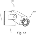
- the means for communication could be arranged in the side surfaces or integrated within the casing as long as the desired contact between the ESL and the central control unit is achieved. If the support arrangement is used for a camera, all of these features are arranged within the camera housing to ensure the desired communication between the camera and the central control system.
- the rear side of the ESL casing is rectangular and substantially flat. In the central area of the rear side, four holes 20 are formed.
- the holes could also be embodied as recesses formed in the rear side.
- the holes 20 are arranged in a predetermined pattern, i.e. in the illustrated embodiment the holes form the pattern of a square with the holes in the corners of the square. Different number of holes or recesses as well as patterns could be used like for example furhter holes arranged in a circle etc.
- the holes 20 are substantially circular and with the same radius.
- the inside surface of the rear part of the casing is formed such that the area surrounding each hole, or recesse, is shaped such that a shoulder 21 extending around the hole, or recesse, is formed. Th shoulder is illustrated in figure 4b and 4c and is intended to co-operate with the support device to attache the ESL to the support device.
- the shoulder 21 either extend around the entire hole 20, or recess, as illustrated in the figures, alternatively around a section of the hole, or recess. If the shoulder extend around a section of the hole, or recess, this section should be on the side of the opening that is facing upwards when the ESL is fitted in the intended position to the support device.
- the shoulder preferably also extend along a section between 90° to 150° around the hole, or recess, such that the ESL could be turned 90 and fitted in either a vertical or horzontal direction.
- the support device 30 comprises a substantially flat support body 31 intended to be secured to a wall, a shelf or a support structure arranged at the desired location of the ESL in the store.
- the support body illustrated in detail in figure 2a and 2b , comprises a number of fastening openings 32 to make it possible to secure the support device by screws or snap-fittings to the wall, shelf or support structure.
- the support device could also be fastened by adhesive to eliminate any damage to the wall, shelf or support structure.
- the support device furthermore comprises a corresponding number of attachment protrusions 33 as the number of recesses in the rear side of the ESL, i.e. in the illustrated embodiment four attachment protrusions 33.
- the attachment protrusions extend substantially transverse from the support body and are arranged in a corresponding pattern on the support body as the holes 20, or recesses, in the rear side of the ESL, i.e. in a square.
- the attachment protrusions have a shape and dimensions corresponding to the shape and dimensions of the holes, or recesses, in the rear side of the ESL to make it possible to fit the attachment protrusions in the holes, or recesses.
- the holes 20 in the rear side of the ESL 10 have a substantially circular shape and the attachment protrusions 33 a corresponding circular cross-section.
- the attachment protrusions extend substantially straight from the support body and has a constant radius before each protrusion is ended by a rounded outer end.
- the extension of the attachment protrusions must correspond to the space inside the holes, or recesses, to ensure that the attachment protrusions fit in the space.
- Each attachment protrusion 33 comprises a cut- out portion formed in the side of the attachment protrusion that is intended to face upwards when the support device 30 is fastened in the intended position on the wall, shelf or support structure such that a support surface is formed in the area of the cut-out portion.
- each attachment protrusion comprises a first surface 34 arranged substantially transverse to the plane of the support body and a second surface 35 extending from the outer end of the first surface substantially parallel to the plane of the support body upwards when the support device is arranged in the intended position.
- the second surface 35 of the support surface is intended to bear against the shoulder 21 extending around the hole 20, or recess, in the rear side of the ESL 10 to maintain the electronic shelf label 10 attached to the support device 30.
- the first surface 34 will be in contact with the peripheral surface surrounding the hole 20 and the second surface 35 will bear against the shoulder to maintain the ESL attached to the support device.
- the support arrangement according to the invention furthermore comprises a releasable locking device 40 arranged to maintain the support surfaces of the support device in contact with the shoulders 21 surrounding the holes 20, or recesses.
- the locking device 40 has a male / female configuration and in the illustrated embodiment of the support arrangement the female part 41 is arranged in the rear side of the ESL 10 and the male part 42 in the support device 30.
- the female part is a substantially circular recess 43 arranged in the center of the square formed by the holes in the rear side of the ESL, illustrated in figure 4b and 4c .
- the male part 42 is a resilient protrusion extending from the support body.
- the resilient protrusion is shaped like an elongated member 44 extending from the support body 31 towards the ESL 10.
- the elongated member 44 has a nob 45 in the outer end with a dimension corresponding to the radius of the circular recess 43 such that the nob in the outer end fit within the recess and locks the ESL to the support device.
- the resilient protrusion is forced towards the rear side of the ESL 10 and as soon as the ESL is in the correct position in relation to the support device the nob 45 snaps into the recess to lock the ESL to the support device.
- the locking device 40 is released by a release element 50 arranged to release the connection between the male 42 and female 43 element, i.e. the circular recess 43 and the nob 45 in the outer end of the elongated member 44.
- the release element 50 comprises an actuator 51 extending substantially parallel to the flat support body 31 from the elongated member 44 outside the periphery of the support body 31 in the plane of the support body.
- the elongated actuator 51 has a forward end 52 arranged adjacent to the male element 42 and a second end arranged in the opposite end of the actuator.
- the length of the actuator is selected such that the second end is hidden behind the ESL 10 but accessible via the space formed behind the ESL between the ESL and the wall, shelf or support structure.
- the actuator 51 is movable along the axis defined by the extension of the elongated actuator between a first position in which the electronic shelf label is attached to the support device and a second position in which the electronic shelf label is released from the support device.
- the release element is movably attached to the support body 31 that have guiding rails 36 arranged on both sides of the elongated actuator to maintain and guide the actuator during movement between the first and second position.
- the release element 50 furthermore comprises two springs 54 arranged to return the elongated actuator 51 to the first position when no force is acting on the second end of the actuator forcing it to the second position to ensure that the ESL is locked to the support device until there is a desire to remove it.
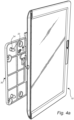
- the different positions of the ESL 10, the support device 30 and the release element 50 are illustrated in figure 4a to 4d to more clearly illustrate the function of the arrangement.
- the release element In the first position, the release element is located separated from the resilient member 44 and the nob is forced into the circular recess 43.
- the actuator 51 When the actuator 51 is moved towards the second position, the forward end 52 of the actuator 51 is sliding towards the elongated member 44 and forces the resilient elongated member 44 towards the support body and away from the ESL such that the nob is removed from the circular recess 43.
- the ESL 10 is moved slightly upwards to disconnect the second surface of the attachment protrusion from the shoulder 21 surrounding the holes 20 in the rear side of the ESL 10 and the ESL 10 is released from the support device 30.
Landscapes
- Physics & Mathematics (AREA)
- General Physics & Mathematics (AREA)
- Engineering & Computer Science (AREA)
- Theoretical Computer Science (AREA)
- Casings For Electric Apparatus (AREA)
Description
- The present invention relates to a support arrangement for a unit used within a retail environment.
- In stores, for example supermarkets etc, electronic shelf labels, also referred to as ESLs, are used for displaying information about the different products offered in the store. The information displayed could be the name and type of product, information regarding the product as well as the price for each of the products. Furthermore, cameras are more frequently used for example to monitor the amount of the goods remaning on the shelves and to ensure that the different products are in the intended order on the shelves.
- The electronic shelf labels and / or cameras are communicating with a central control unit that makes it possible to frequently update, and change the information displayed on the labels which saves a considerable amount of time for the persons working in the store, especially if the number of different products sold in the store is high. As an example, a supermarket offers between 5000 and 20000 different products.
- The most common type of electronic shelf labels are small and arranged side by side along the forward edge of shelves or desks adjacent to the product each ESL is intended to market but there is an increasing demand for larger displays in order to increase the size of the text and/or the amount of information that could be displayed, and cameras comprising the required components are ofte larger than conventional electronic shelf labels. The larger units, i.e. electronic shelf labels and cameras, however requires new flexible support arrangements and there is consequently a need for an improved support arrangment for larger units, i.e. electronic shelf labels and cameras. Document
WO2010/107366-A is considered the closest prior art and discloses all the features of the preamble of claim 1. - The present invention, defined in the appended claims, provides a support arrangement for a unit used within a retail environment that to at least some extent fulfils the needs defined above.
The claimed support arrangement for a unit used within a retail environment comprises: - a unit comprising a casing with a substantially flat rear side, at least three recesses arranged in a predetermined pattern are formed in the rear side of the electronic shelf label, said recesses are shaped such that a shoulder extending around at least a section of the opening of the recess in the rear side;
- a support device comprising a substantially flat support body intended to be secured to a wall, a shelf or a support structure, said support device comprises a corresponding number of attachment protrusions as the number of recesses, said attachment protrusions have shape and dimension corresponding to the recesses and each comprising a support surface intended to bear against the shoulder of the recesses to maintain the unit attached to the support device; and
- a releasable locking device arranged to maintain the support surfaces in contact with the shoulders in the recesses, said locking device has a male / female configuration.
- The claimed support arrangement fulfils the needs defined above by providing a new type of support that in combination with the design of the unit ensures a reliable securing of the unit still making it easy to remove the unit when needed. Furthermore, the support arrangement is arranged behind the unit and give the unit the desired appearance with the support arrangement hidden behind. The position behind the unit is also favourable since the release of the unit requires knowledge about the arrangement which prevents unintentional removal by un-authorized persons.
- In one embodiment of the support arrangement, the at least three recesses and corresponding attachment protrusions are arranged in a pattern that makes it possible to secure the unit to the support device in both a first and a second position, said first and second position are located 90° from each other. This embodiment is favorable since many units have a rectangular display, or field of view, and this embodiment of the arrangement makes it possible to attach the unit either in a position where the display or field of view extends horizontally or vertically. Furthermore, this embodiment provides a reliable and stable support since the attachment protrusions and recesses could be arranged in a two-dimensional pattern.
- In one embodiment of the support arrangement, the support body has a rectangular or circular shape with smaller extension than the electronic shelf label in the plane of the rear side. This embodiment of the support body ensures that the support device is hidden behind the unit.
- In one embodiment of the support arrangement, the number of recesses and attachment protrusions are at least four and arranged in the pattern of a square. This embodiment provides a flexible and stable support for the unit since the attachment protrusions and recesses are spread over a larger area
- The releasable locking device comprises a male element, a female element and a release element arranged to release the connection between the male and female element to release the electronic shelf label from the support device. The male / female configuration provides the desired reliable securing of the unit to the support device and the release element makes it possible to the release the unit when desired.
- The male element and female element are arranged between the rear side of the unit and the flat support body, and the release element comprises an actuator extending substantially parallel to the flat support body outside the support body in the plane of the support body. In this embodiment of the arrangement, the different parts of the arrangement are protected between the support device and the unit.
- In one embodiment of the support arrangement, the female element of the coupling device is a recess formed in the rear side of the electronic shelf label and the male part is a resilient protrusion arranged in the support body.
- In one embodiment of the support arrangement, the release element is movable between a first position in which the electronic shelf label is attached to the support device and a second position in which the electronic shelf label is released from the support device.
- In one embodiment of the support arrangement, the release element in the second position is arranged to force the resilient male element into a non-engagement position with the female element.
- In one embodiment of the support arrangement, the release element is resiliently arranged in the support device such that it is returned to the first position if force is acting on the release element.
- In one embodiment of the support arrangement, the unit is an electronic shelf label or a camera.
- The different described embodiments of the invention could of course be combined in different ways without departing from the scope of the invention that will be described more in detail in the detailed description.
- One embodiment of the support arrangement according to the invention is illustrated in the appended figures.
-
Figure 1a illustrates an exploded perspective view of the different elements of the support arrangement. -
Figure 2a illustrates a perspective views of the support device. -
Figure 2b illustrates perspective views of the support device and the release element fitted in the support device. -
Figure 3 illustrates a perspective view of the release element. -
Figure 4a to 4d illustrates different view of the arrangement before and after an electronic shelf label is fitted to the support device. - In
figure 1a an exploded perspective view of the different elements of the support arrangement are illustrated in order to more clarly illustrate the technic aspects of the support arrangement. - In
figure 1a a unit in embodied as anelectronic shelf label 10, also referred to as ESL, is illustrated. The ESL comprises acasing 11 and adisplay area 12 that is intended to display the desired information such as for example price, ingredients, origin etc. The casing is substantially rectangular with an upper 13 andlower side 14 arranged parallel to each other, twoside surfaces 15, and a forward 16 andrear side 17. Infigure 1a the rear part of thecasing 11 is illustrated exploded from the rest of the casing, but this is only to be able to illustrate essential features of the rear side more clearly. Theforward side 16 is substantially flat and comprises thedisplay area 18. The casing is for example made of a plastic material that provides the desired structural strength as well as the desired appearance of theESL 10.
In the forward side of the ESL, means 19 for communication between the ESL and a central control system is arranged. In the illustrated ESL, this communication involves means for infra-red optical communication with an in the store centrally arranged control unit. Other alternatives for communication between the ESL and the central control system are however possible and the means for communication arranged in the ESL are then modified or adapted to the desired system for communication. In a further embodiment of an ESL, the means for communication could be arranged in the side surfaces or integrated within the casing as long as the desired contact between the ESL and the central control unit is achieved. If the support arrangement is used for a camera, all of these features are arranged within the camera housing to ensure the desired communication between the camera and the central control system. - The rear side of the ESL casing is rectangular and substantially flat. In the central area of the rear side, four
holes 20 are formed. The holes could also be embodied as recesses formed in the rear side. Theholes 20 are arranged in a predetermined pattern, i.e. in the illustrated embodiment the holes form the pattern of a square with the holes in the corners of the square. Different number of holes or recesses as well as patterns could be used like for example furhter holes arranged in a circle etc. Theholes 20 are substantially circular and with the same radius. The inside surface of the rear part of the casing is formed such that the area surrounding each hole, or recesse, is shaped such that ashoulder 21 extending around the hole, or recesse, is formed. Th shoulder is illustrated infigure 4b and4c and is intended to co-operate with the support device to attache the ESL to the support device. - The
shoulder 21 either extend around theentire hole 20, or recess, as illustrated in the figures, alternatively around a section of the hole, or recess. If the shoulder extend around a section of the hole, or recess, this section should be on the side of the opening that is facing upwards when the ESL is fitted in the intended position to the support device. The shoulder preferably also extend along a section between 90° to 150° around the hole, or recess, such that the ESL could be turned 90 and fitted in either a vertical or horzontal direction. - The
support device 30 comprises a substantiallyflat support body 31 intended to be secured to a wall, a shelf or a support structure arranged at the desired location of the ESL in the store. The support body, illustrated in detail infigure 2a and 2b , comprises a number offastening openings 32 to make it possible to secure the support device by screws or snap-fittings to the wall, shelf or support structure. The support device could also be fastened by adhesive to eliminate any damage to the wall, shelf or support structure. The support device furthermore comprises a corresponding number ofattachment protrusions 33 as the number of recesses in the rear side of the ESL, i.e. in the illustrated embodiment fourattachment protrusions 33. The attachment protrusions extend substantially transverse from the support body and are arranged in a corresponding pattern on the support body as theholes 20, or recesses, in the rear side of the ESL, i.e. in a square. The attachment protrusions have a shape and dimensions corresponding to the shape and dimensions of the holes, or recesses, in the rear side of the ESL to make it possible to fit the attachment protrusions in the holes, or recesses. - In the illustrated embodiment of the support arrangement, the
holes 20 in the rear side of theESL 10 have a substantially circular shape and the attachment protrusions 33 a corresponding circular cross-section. The attachment protrusions extend substantially straight from the support body and has a constant radius before each protrusion is ended by a rounded outer end. The extension of the attachment protrusions must correspond to the space inside the holes, or recesses, to ensure that the attachment protrusions fit in the space. Eachattachment protrusion 33 comprises a cut- out portion formed in the side of the attachment protrusion that is intended to face upwards when thesupport device 30 is fastened in the intended position on the wall, shelf or support structure such that a support surface is formed in the area of the cut-out portion. The support surface could be embodied in different ways and in the illustrated embodiment each attachment protrusion comprises afirst surface 34 arranged substantially transverse to the plane of the support body and asecond surface 35 extending from the outer end of the first surface substantially parallel to the plane of the support body upwards when the support device is arranged in the intended position. Thesecond surface 35 of the support surface is intended to bear against theshoulder 21 extending around thehole 20, or recess, in the rear side of theESL 10 to maintain theelectronic shelf label 10 attached to thesupport device 30. In the illustrated embodiment thefirst surface 34 will be in contact with the peripheral surface surrounding thehole 20 and thesecond surface 35 will bear against the shoulder to maintain the ESL attached to the support device. - The support arrangement according to the invention furthermore comprises a
releasable locking device 40 arranged to maintain the support surfaces of the support device in contact with theshoulders 21 surrounding theholes 20, or recesses. The lockingdevice 40 has a male / female configuration and in the illustrated embodiment of the support arrangement the female part 41 is arranged in the rear side of theESL 10 and themale part 42 in thesupport device 30. - In the illustrated embodiment the female part is a substantially
circular recess 43 arranged in the center of the square formed by the holes in the rear side of the ESL, illustrated infigure 4b and4c . Themale part 42 is a resilient protrusion extending from the support body. The resilient protrusion is shaped like anelongated member 44 extending from thesupport body 31 towards theESL 10. Theelongated member 44 has a nob 45 in the outer end with a dimension corresponding to the radius of thecircular recess 43 such that the nob in the outer end fit within the recess and locks the ESL to the support device. The resilient protrusion is forced towards the rear side of theESL 10 and as soon as the ESL is in the correct position in relation to the support device the nob 45 snaps into the recess to lock the ESL to the support device. - The locking
device 40 is released by arelease element 50 arranged to release the connection between the male 42 and female 43 element, i.e. thecircular recess 43 and the nob 45 in the outer end of theelongated member 44. Therelease element 50 comprises anactuator 51 extending substantially parallel to theflat support body 31 from theelongated member 44 outside the periphery of thesupport body 31 in the plane of the support body. - The
elongated actuator 51 has aforward end 52 arranged adjacent to themale element 42 and a second end arranged in the opposite end of the actuator. The length of the actuator is selected such that the second end is hidden behind theESL 10 but accessible via the space formed behind the ESL between the ESL and the wall, shelf or support structure. Theactuator 51 is movable along the axis defined by the extension of the elongated actuator between a first position in which the electronic shelf label is attached to the support device and a second position in which the electronic shelf label is released from the support device. The release element is movably attached to thesupport body 31 that have guidingrails 36 arranged on both sides of the elongated actuator to maintain and guide the actuator during movement between the first and second position. Therelease element 50 furthermore comprises twosprings 54 arranged to return theelongated actuator 51 to the first position when no force is acting on the second end of the actuator forcing it to the second position to ensure that the ESL is locked to the support device until there is a desire to remove it. - The different positions of the
ESL 10, thesupport device 30 and therelease element 50 are illustrated infigure 4a to 4d to more clearly illustrate the function of the arrangement. In the first position, the release element is located separated from theresilient member 44 and the nob is forced into thecircular recess 43. When theactuator 51 is moved towards the second position, theforward end 52 of theactuator 51 is sliding towards theelongated member 44 and forces the resilientelongated member 44 towards the support body and away from the ESL such that the nob is removed from thecircular recess 43. Once the nob is fully removed from the circular recess theESL 10 is moved slightly upwards to disconnect the second surface of the attachment protrusion from theshoulder 21 surrounding theholes 20 in the rear side of theESL 10 and theESL 10 is released from thesupport device 30. - The different embodiments described above could all be combined and modified in different ways without departing from the scope of the invention that is defined by the appended claims.
Claims (9)
- Support arrangement for a unit (10) used within a retail environment, said arrangement comprising:a unit (10) comprising a casing (11) with a substantially flat rear side (13), at least three recesses (20) arranged in a predetermined pattern are formed in the rear side (13) of the unit (10), said recesses (20) are shaped such that a shoulder (21) extending around at least a section of the recess (20) in the rear side is formed;a support device (30) comprising a substantially flat support body (31) intended to be secured to a wall, a shelf or a support structure, said support device (30) comprises a corresponding number of attachment protrusions (33) as the number of recesses (20), said attachment protrusions (33) have shape and dimension corresponding to shape and dimension of the recesses (20) and each comprising a support surface (35) intended to bear against the shoulder (21) of the recesses (20) to maintain the unit (10) attached to the support device (30); anda releasable locking device (40) arranged to maintain the support surfaces (35) in contact with the shoulders (21) in the recesses (20), said locking device (40) has a male / female configuration and comprises a male element (42), a female (41) element and a release element (50) arranged to release the connection between the male (42) and female (41) element to release the unit (10) from the support device (30), characterized in thatthe male element (42) and female element (41) are arranged between the rear side (13) of the unit (10) and the flat support body (31), and the release element (50) comprises an actuator (51) extending substantially parallel to the flat support body (31) outside the support body (31) in the plane of the support body (31).
- Support arrangement according to claim 1, wherein the at least three recesses (20) and corresponding attachment protrusions (33) are arranged in a pattern that makes it possible to secure the unit (10) to the support device (30) in both a first and a second position, said first and second position are located 90° from each other.
- Support arrangement according to claim 1 or 2, wherein the support body (31) has a substantially rectangular, circular or oval shape with smaller extension than the unit (10) in the plane of the rear side (13).
- Support arrangement according to any one of the previous claims, wherein the number of recesses (20) and attachment protrusions (33) are at least four and arranged in the pattern of a square.
- Support arrangement according to claim 1, wherein the female element (41) of the coupling device is a recess (43) formed in the rear side (13) of the unit (10) and the male element (42) is a resilient protrusion arranged in the support body.
- Support arrangement according to claim 5, wherein the release element (50) is movable between a first position in which the unit (10) is attached to the support device (30) and a second position in which the unit (10) is released from the support device (30).
- Support arrangement according to claim 6, wherein the release element (50) in the second position is arranged to force the resilient male element (42) into a non-engagement position with the female element (41).
- Support arrangement according to claim 7, wherein the release element (50) is resiliently arranged in the support device (30) such that it is returned to the first position if no force is acting on the release element.
- Support arrangement according to anyone of the previous claims, wherein the unit is an electronic shelf label (10) or a camera.
Applications Claiming Priority (2)
| Application Number | Priority Date | Filing Date | Title |
|---|---|---|---|
| SE1951338 | 2019-11-25 | ||
| PCT/EP2020/083258 WO2021105149A1 (en) | 2019-11-25 | 2020-11-24 | Support arrangement for a unit used within a retail environment |
Publications (3)
| Publication Number | Publication Date |
|---|---|
| EP4066233A1 EP4066233A1 (en) | 2022-10-05 |
| EP4066233C0 EP4066233C0 (en) | 2025-01-08 |
| EP4066233B1 true EP4066233B1 (en) | 2025-01-08 |
Family
ID=73598843
Family Applications (1)
| Application Number | Title | Priority Date | Filing Date |
|---|---|---|---|
| EP20815750.3A Active EP4066233B1 (en) | 2019-11-25 | 2020-11-24 | Support arrangement for a unit used within a retail environment |
Country Status (4)
| Country | Link |
|---|---|
| US (1) | US11670196B2 (en) |
| EP (1) | EP4066233B1 (en) |
| CA (1) | CA3161784A1 (en) |
| WO (1) | WO2021105149A1 (en) |
Families Citing this family (1)
| Publication number | Priority date | Publication date | Assignee | Title |
|---|---|---|---|---|
| US12664915B2 (en) * | 2023-06-20 | 2026-06-23 | Vusiongroup Gmbh | Fastening element for fastening or fixing a display unit to a support device and display unit |
Family Cites Families (7)
| Publication number | Priority date | Publication date | Assignee | Title |
|---|---|---|---|---|
| US3899841A (en) * | 1974-03-04 | 1975-08-19 | Sol J Berger | Coupon display and clip therefor |
| SE534688C2 (en) | 2009-03-20 | 2011-11-15 | Pricer Ab | Electronic shelf label and holder including locking mechanism, and locking mechanism |
| SE534425C2 (en) * | 2009-03-20 | 2011-08-16 | Pricer Ab | Electronic shelf label and holder including locking mechanism, and locking mechanism |
| US9015977B2 (en) * | 2012-11-01 | 2015-04-28 | Cassandra J. Mason | System for changing the appearance of framed components |
| US20150056009A1 (en) | 2013-08-23 | 2015-02-26 | GM Global Technology Operations LLC | Elastic averaging snap member aligning and fastening system |
| WO2016111615A1 (en) | 2015-01-09 | 2016-07-14 | Opticon Sensors Europe B.V. | Coupling device, and mounting system |
| CN114370563B (en) * | 2020-10-15 | 2024-08-09 | 华硕电脑股份有限公司 | Screen Fixing Device |
-
2020
- 2020-11-24 EP EP20815750.3A patent/EP4066233B1/en active Active
- 2020-11-24 WO PCT/EP2020/083258 patent/WO2021105149A1/en not_active Ceased
- 2020-11-24 US US17/779,433 patent/US11670196B2/en active Active
- 2020-11-24 CA CA3161784A patent/CA3161784A1/en active Pending
Also Published As
| Publication number | Publication date |
|---|---|
| EP4066233A1 (en) | 2022-10-05 |
| CA3161784A1 (en) | 2021-06-03 |
| US20220398945A1 (en) | 2022-12-15 |
| US11670196B2 (en) | 2023-06-06 |
| WO2021105149A1 (en) | 2021-06-03 |
| EP4066233C0 (en) | 2025-01-08 |
Similar Documents
| Publication | Publication Date | Title |
|---|---|---|
| US5816550A (en) | Shelf mounting arrangements for electronic shelf displays or similar articles | |
| EP3719782A1 (en) | Electronic self label and sign | |
| US11304553B2 (en) | Hanger system with hanger coupling member | |
| EP2742502B1 (en) | Support for communication elements in points of sale of products | |
| EP1735662B1 (en) | Adapter for attaching an electronic shelf label to a blister hook | |
| US20100200525A1 (en) | Adjustable Display Device | |
| US8898979B2 (en) | Visual patterning for a cover system using modular units on a patterned backing | |
| CN103533789B (en) | Electronic product panel | |
| US11670196B2 (en) | Support arrangement for a unit used within a retail environment | |
| JP2003233323A (en) | Display holder | |
| USD559581S1 (en) | Retail merchandising unit | |
| EP3884482B1 (en) | Arrangement for supporting an electronic shelf label in a desired angle | |
| AU2005100503A4 (en) | Multi-functional System | |
| US20060278590A1 (en) | Display device particularly for electronic display of prices | |
| US6767234B1 (en) | Hook and hang display system with plug-in bullnose header module | |
| JP3148719U (en) | Display holder | |
| JP4452055B2 (en) | Rail for price cards | |
| CN217606518U (en) | Connecting rod display device | |
| CN218074303U (en) | Hanging type display shelf | |
| JP3799052B1 (en) | Product hanging display | |
| KR20110077817A (en) | Rail for mounting electronic price indicator | |
| CA2761451A1 (en) | Multi-direction garment display module | |
| CN206365679U (en) | Commodity transfer member | |
| JP2002345609A (en) | Shelf equipment | |
| WO2011124981A1 (en) | Display assemgly for shelves |
Legal Events
| Date | Code | Title | Description |
|---|---|---|---|
| STAA | Information on the status of an ep patent application or granted ep patent |
Free format text: STATUS: UNKNOWN |
|
| STAA | Information on the status of an ep patent application or granted ep patent |
Free format text: STATUS: THE INTERNATIONAL PUBLICATION HAS BEEN MADE |
|
| PUAI | Public reference made under article 153(3) epc to a published international application that has entered the european phase |
Free format text: ORIGINAL CODE: 0009012 |
|
| STAA | Information on the status of an ep patent application or granted ep patent |
Free format text: STATUS: REQUEST FOR EXAMINATION WAS MADE |
|
| 17P | Request for examination filed |
Effective date: 20220511 |
|
| AK | Designated contracting states |
Kind code of ref document: A1 Designated state(s): AL AT BE BG CH CY CZ DE DK EE ES FI FR GB GR HR HU IE IS IT LI LT LU LV MC MK MT NL NO PL PT RO RS SE SI SK SM TR |
|
| DAV | Request for validation of the european patent (deleted) | ||
| DAX | Request for extension of the european patent (deleted) | ||
| GRAP | Despatch of communication of intention to grant a patent |
Free format text: ORIGINAL CODE: EPIDOSNIGR1 |
|
| STAA | Information on the status of an ep patent application or granted ep patent |
Free format text: STATUS: GRANT OF PATENT IS INTENDED |
|
| INTG | Intention to grant announced |
Effective date: 20241002 |
|
| GRAS | Grant fee paid |
Free format text: ORIGINAL CODE: EPIDOSNIGR3 |
|
| GRAA | (expected) grant |
Free format text: ORIGINAL CODE: 0009210 |
|
| STAA | Information on the status of an ep patent application or granted ep patent |
Free format text: STATUS: THE PATENT HAS BEEN GRANTED |
|
| AK | Designated contracting states |
Kind code of ref document: B1 Designated state(s): AL AT BE BG CH CY CZ DE DK EE ES FI FR GB GR HR HU IE IS IT LI LT LU LV MC MK MT NL NO PL PT RO RS SE SI SK SM TR |
|
| REG | Reference to a national code |
Ref country code: GB Ref legal event code: FG4D |
|
| REG | Reference to a national code |
Ref country code: CH Ref legal event code: EP |
|
| REG | Reference to a national code |
Ref country code: DE Ref legal event code: R096 Ref document number: 602020044588 Country of ref document: DE |
|
| REG | Reference to a national code |
Ref country code: IE Ref legal event code: FG4D |
|
| U01 | Request for unitary effect filed |
Effective date: 20250117 |
|
| U07 | Unitary effect registered |
Designated state(s): AT BE BG DE DK EE FI FR IT LT LU LV MT NL PT RO SE SI Effective date: 20250123 |
|
| PG25 | Lapsed in a contracting state [announced via postgrant information from national office to epo] |
Ref country code: RS Free format text: LAPSE BECAUSE OF FAILURE TO SUBMIT A TRANSLATION OF THE DESCRIPTION OR TO PAY THE FEE WITHIN THE PRESCRIBED TIME-LIMIT Effective date: 20250408 |
|
| PG25 | Lapsed in a contracting state [announced via postgrant information from national office to epo] |
Ref country code: PL Free format text: LAPSE BECAUSE OF FAILURE TO SUBMIT A TRANSLATION OF THE DESCRIPTION OR TO PAY THE FEE WITHIN THE PRESCRIBED TIME-LIMIT Effective date: 20250108 |
|
| PG25 | Lapsed in a contracting state [announced via postgrant information from national office to epo] |
Ref country code: ES Free format text: LAPSE BECAUSE OF FAILURE TO SUBMIT A TRANSLATION OF THE DESCRIPTION OR TO PAY THE FEE WITHIN THE PRESCRIBED TIME-LIMIT Effective date: 20250108 |
|
| PG25 | Lapsed in a contracting state [announced via postgrant information from national office to epo] |
Ref country code: NO Free format text: LAPSE BECAUSE OF FAILURE TO SUBMIT A TRANSLATION OF THE DESCRIPTION OR TO PAY THE FEE WITHIN THE PRESCRIBED TIME-LIMIT Effective date: 20250408 Ref country code: IS Free format text: LAPSE BECAUSE OF FAILURE TO SUBMIT A TRANSLATION OF THE DESCRIPTION OR TO PAY THE FEE WITHIN THE PRESCRIBED TIME-LIMIT Effective date: 20250508 |
|
| PG25 | Lapsed in a contracting state [announced via postgrant information from national office to epo] |
Ref country code: HR Free format text: LAPSE BECAUSE OF FAILURE TO SUBMIT A TRANSLATION OF THE DESCRIPTION OR TO PAY THE FEE WITHIN THE PRESCRIBED TIME-LIMIT Effective date: 20250108 |
|
| PG25 | Lapsed in a contracting state [announced via postgrant information from national office to epo] |
Ref country code: GR Free format text: LAPSE BECAUSE OF FAILURE TO SUBMIT A TRANSLATION OF THE DESCRIPTION OR TO PAY THE FEE WITHIN THE PRESCRIBED TIME-LIMIT Effective date: 20250409 |
|
| PG25 | Lapsed in a contracting state [announced via postgrant information from national office to epo] |
Ref country code: SM Free format text: LAPSE BECAUSE OF FAILURE TO SUBMIT A TRANSLATION OF THE DESCRIPTION OR TO PAY THE FEE WITHIN THE PRESCRIBED TIME-LIMIT Effective date: 20250108 |
|
| PG25 | Lapsed in a contracting state [announced via postgrant information from national office to epo] |
Ref country code: CZ Free format text: LAPSE BECAUSE OF FAILURE TO SUBMIT A TRANSLATION OF THE DESCRIPTION OR TO PAY THE FEE WITHIN THE PRESCRIBED TIME-LIMIT Effective date: 20250108 |
|
| PG25 | Lapsed in a contracting state [announced via postgrant information from national office to epo] |
Ref country code: SK Free format text: LAPSE BECAUSE OF FAILURE TO SUBMIT A TRANSLATION OF THE DESCRIPTION OR TO PAY THE FEE WITHIN THE PRESCRIBED TIME-LIMIT Effective date: 20250108 |
|
| PLBE | No opposition filed within time limit |
Free format text: ORIGINAL CODE: 0009261 |
|
| STAA | Information on the status of an ep patent application or granted ep patent |
Free format text: STATUS: NO OPPOSITION FILED WITHIN TIME LIMIT |
|
| REG | Reference to a national code |
Ref country code: CH Ref legal event code: L10 Free format text: ST27 STATUS EVENT CODE: U-0-0-L10-L00 (AS PROVIDED BY THE NATIONAL OFFICE) Effective date: 20251119 |
|
| U20 | Renewal fee for the european patent with unitary effect paid |
Year of fee payment: 6 Effective date: 20251016 |
|
| 26N | No opposition filed |
Effective date: 20251009 |
|
| PGFP | Annual fee paid to national office [announced via postgrant information from national office to epo] |
Ref country code: GB Payment date: 20251016 Year of fee payment: 6 |
|
| REG | Reference to a national code |
Ref country code: CH Ref legal event code: H13 Free format text: ST27 STATUS EVENT CODE: U-0-0-H10-H13 (AS PROVIDED BY THE NATIONAL OFFICE) Effective date: 20260623 |
|
| PG25 | Lapsed in a contracting state [announced via postgrant information from national office to epo] |
Ref country code: MC Free format text: LAPSE BECAUSE OF FAILURE TO SUBMIT A TRANSLATION OF THE DESCRIPTION OR TO PAY THE FEE WITHIN THE PRESCRIBED TIME-LIMIT Effective date: 20250108 |
|
| PG25 | Lapsed in a contracting state [announced via postgrant information from national office to epo] |
Ref country code: CH Free format text: LAPSE BECAUSE OF NON-PAYMENT OF DUE FEES Effective date: 20251130 |