EP4065953B1 - Method and apparatus for detecting corrosion - Google Patents
Method and apparatus for detecting corrosion Download PDFInfo
- Publication number
- EP4065953B1 EP4065953B1 EP20820472.7A EP20820472A EP4065953B1 EP 4065953 B1 EP4065953 B1 EP 4065953B1 EP 20820472 A EP20820472 A EP 20820472A EP 4065953 B1 EP4065953 B1 EP 4065953B1
- Authority
- EP
- European Patent Office
- Prior art keywords
- current
- corrosion
- scan
- detecting
- lsv
- Prior art date
- Legal status (The legal status is an assumption and is not a legal conclusion. Google has not performed a legal analysis and makes no representation as to the accuracy of the status listed.)
- Active
Links
Images



Classifications
-
- G—PHYSICS
- G01—MEASURING; TESTING
- G01N—INVESTIGATING OR ANALYSING MATERIALS BY DETERMINING THEIR CHEMICAL OR PHYSICAL PROPERTIES
- G01N17/00—Investigating resistance of materials to the weather, to corrosion, or to light
- G01N17/02—Electrochemical measuring systems for weathering, corrosion or corrosion-protection measurement
-
- G—PHYSICS
- G01—MEASURING; TESTING
- G01N—INVESTIGATING OR ANALYSING MATERIALS BY DETERMINING THEIR CHEMICAL OR PHYSICAL PROPERTIES
- G01N17/00—Investigating resistance of materials to the weather, to corrosion, or to light
- G01N17/006—Investigating resistance of materials to the weather, to corrosion, or to light of metals
-
- G—PHYSICS
- G01—MEASURING; TESTING
- G01N—INVESTIGATING OR ANALYSING MATERIALS BY DETERMINING THEIR CHEMICAL OR PHYSICAL PROPERTIES
- G01N27/00—Investigating or analysing materials by the use of electric, electrochemical, or magnetic means
- G01N27/26—Investigating or analysing materials by the use of electric, electrochemical, or magnetic means by investigating electrochemical variables; by using electrolysis or electrophoresis
- G01N27/28—Electrolytic cell components
- G01N27/30—Electrodes, e.g. test electrodes; Half-cells
-
- G—PHYSICS
- G01—MEASURING; TESTING
- G01N—INVESTIGATING OR ANALYSING MATERIALS BY DETERMINING THEIR CHEMICAL OR PHYSICAL PROPERTIES
- G01N27/00—Investigating or analysing materials by the use of electric, electrochemical, or magnetic means
- G01N27/26—Investigating or analysing materials by the use of electric, electrochemical, or magnetic means by investigating electrochemical variables; by using electrolysis or electrophoresis
- G01N27/28—Electrolytic cell components
- G01N27/30—Electrodes, e.g. test electrodes; Half-cells
- G01N27/327—Biochemical electrodes, e.g. electrical or mechanical details for in vitro measurements
- G01N27/3275—Sensing specific biomolecules, e.g. nucleic acid strands, based on an electrode surface reaction
- G01N27/3277—Sensing specific biomolecules, e.g. nucleic acid strands, based on an electrode surface reaction being a redox reaction, e.g. detection by cyclic voltammetry
-
- G—PHYSICS
- G01—MEASURING; TESTING
- G01N—INVESTIGATING OR ANALYSING MATERIALS BY DETERMINING THEIR CHEMICAL OR PHYSICAL PROPERTIES
- G01N27/00—Investigating or analysing materials by the use of electric, electrochemical, or magnetic means
- G01N27/26—Investigating or analysing materials by the use of electric, electrochemical, or magnetic means by investigating electrochemical variables; by using electrolysis or electrophoresis
- G01N27/416—Systems
- G01N27/42—Measuring deposition or liberation of materials from an electrolyte; Coulometry, i.e. measuring coulomb-equivalent of material in an electrolyte
-
- G—PHYSICS
- G01—MEASURING; TESTING
- G01N—INVESTIGATING OR ANALYSING MATERIALS BY DETERMINING THEIR CHEMICAL OR PHYSICAL PROPERTIES
- G01N27/00—Investigating or analysing materials by the use of electric, electrochemical, or magnetic means
- G01N27/26—Investigating or analysing materials by the use of electric, electrochemical, or magnetic means by investigating electrochemical variables; by using electrolysis or electrophoresis
- G01N27/416—Systems
- G01N27/48—Systems using polarography, i.e. measuring changes in current under a slowly-varying voltage
-
- G—PHYSICS
- G01—MEASURING; TESTING
- G01N—INVESTIGATING OR ANALYSING MATERIALS BY DETERMINING THEIR CHEMICAL OR PHYSICAL PROPERTIES
- G01N33/00—Investigating or analysing materials by specific methods not covered by groups G01N1/00 - G01N31/00
- G01N33/20—Metals
-
- G—PHYSICS
- G06—COMPUTING OR CALCULATING; COUNTING
- G06F—ELECTRIC DIGITAL DATA PROCESSING
- G06F2218/00—Aspects of pattern recognition specially adapted for signal processing
- G06F2218/12—Classification; Matching
Definitions
- the present invention relates to the detection of corrosion, and more particularly to detection of corrosion using electrochemical techniques.
- Corrosion of medical instruments and objects is an everyday phenomenon in hospital environments, for example. It originates, for instance, from residues such as body fluids, which provide an ideal growth substrate for various microbes that might start deteriorating the surface in question through corrosion.
- the present state-of-art detection of incipient corrosion is based on machine vision, which has several shortcomings. Firstly, many aging objects develop darker passivation layer spots, which give rise to a high number of false positives. Secondly, as any visual means of detection is only capable of evaluating surfaces in the field of view, corrosion in "hidden places" such as hinges of clamps, or in the inner sides of structures, such as stents and tubes, cannot be evaluated reliably with existing techniques.
- Document GB 2048294 discloses a method in which corrosion current of a coated metallic material is detected.
- Document CN 10644682 A discloses a method of measuring a current density in hydrogen evaluation though a reinforced steel bar in a reinforced concrete structure.
- electrolyte NaCl solution
- electrochemical techniques cyclic potentiodynamic polarization
- An object of the present invention is to provide a method and an apparatus for implementing the method so as to overcome the above problem relating to detecting corrosion on instruments with complex geometries.
- the object of the invention is achieved by a method and an apparatus which are characterized by what is stated in the independent claims.
- the preferred embodiments of the invention are disclosed in the dependent claims.
- the invention is based on the idea of utilization of electrochemical techniques to enable an analysis of all exposed surfaces.
- the inspected object is immersed in an electrolyte, and a current response can be used for detecting the corrosion.
- Electrochemical techniques enable to obtain an indication of corrosion even if the corrosion is not visible. Further, with electrochemical techniques, very small amounts of corrosion products on a large non-corroded surface can be detected which would be hard to detect with known methods and devices which are based on visual inspection. Even further, the invention enables to detect corroded surfaces and does not require that the corrosion process is ongoing.
- the method and apparatus of the invention are able to provide accurate results with minimal false-positive results.
- the method does not react to harmless surface alterations and alerts the user only when the presence of iron oxide species is detected.
- the invention further enables to inspect objects with complex forms without losing the accuracy of the inspection and without harming or destroying the inspected objects as the corrosion current is not flowing.
- the inspection provides reliable results in connection with non-visible internal structures.
- the invention can also be applied to various automated quality control processes.
- LSV linear sweep voltammetry
- CV cyclic voltammetry
- the object to be inspected is immersed in an electrolyte and the presence of corrosion products on the surfaces of the object is detected by electrochemical techniques based on the current originating from the redox reaction of iron.
- the object to be inspected may comprise one or multiple medical instruments, for example.
- the electrochemical techniques include linear sweep voltammetry (LSV) and cyclic voltammetry (CV). With LSV or CV, a sweeping voltage is provided in an electrode and a current response is detected. Based on the current response it can be concluded whether corrosion has occurred on the surface of the inspected object.
- the corrosion on the surface of the inspected object may be due to the corrosion process that has brought iron oxides to the surface or the iron oxides may be due to contact with other corroded objects, for example.
- the presence of corrosion which is detected with the invention does not require that the corrosion process is ongoing as the detection is based on the redox reaction of the iron in iron oxide and more specifically on the electrical current originating from the redox reaction.
- the voltage sweep rate should be selected to be preferably in the range between 5mV/s and 100 mV/s to facilitate identification of the surface reactions, i.e. the presence of iron(oxides).
- a sweeping voltage is applied between the electrodes and a current response is measured.
- the capacitive current is prevailing. If the inspected object has corrosion, i.e. iron(oxides), the current response to the sweeping voltage displays an alteration of the signal in a certain voltage area.
- the current is due to the redox conversion between two charge states of iron, the corresponding electron transfer through the external circuit and the ionic charge balancing. More specifically, the two states of iron are Fe 2+ and Fe 3+ , and the detected current is due to the transfer of electrons between these two states.
- a suitable electrolyte is, for example, a synthetic physiological fluid which is also known as IV-fluid.
- an electrochemical reaction is obtained using a setup, in which the electrolyte is preferably the IV fluid.
- the inspected objects in the electrolyte are acting as a working electrode and an electrolyte vessel acts as a counter electrode.
- a reference electrode is provided to complete the required three-electrode setup.
- the third electrode is an Ag/AgCl reference electrode.
- a reference electrode is suitable as the physiological fluid is used as an electrolyte is sufficiently high in chloride content.
- Ag/AgCl reference electrode has been found to be a suitable reference electrode.
- other reference electrodes can also be employed without departing from the invention.
- the use of IV-fluid is also suitable as it is readily available in hospital environments, for example. Further, the properties of the fluid are not harmful to the instruments which are being scanned.
- Other suitable reference electrodes include calomel electrodes (SCE) and reversible hydrogen electrodes (RHE, SHE), for example. With different electrodes, a different electrolyte may have to be chosen.
- the potential window in which the voltage change is carried out has to be adjusted according to the selected reference electrode in a known manner.
- Ag/AgCl reference electrode is used as the electrode is known to be stable and durable in the intended chemical surrounding.
- the electrolyte used in the invention is preferably a water-based electrolyte having salt (chloride) content.
- IV-fluid has the properties which are needed for the electrolyte.
- the LSV or CV scan voltage is changed and current between the electrodes is measured.
- the obtained current originating from the electrolysis reaction is small.
- the current corresponding to the surface alteration being studied is obtained typically in a certain part of the voltage sweep, and the presence of current indicating the corrosion can be detected from the current response.
- the current indicating corrosion is detected from the first or second derivative of the current.
- the first derivative of the current represents the change rate of current and the second derivative of the current represents the rate of the current change.
- the resulting current changes approximately linearly, i.e. it increases or decreases without any abrupt changes. This linear change is due to the capacitive current.
- the current has an additional component originating from the redox conversion of iron species if these are present on the surface. This additional current component is indicative of the corrosion of the object.
- the current peak or an alteration in the current signal is detectable as such or from the first or the second derivative of the current.
- Figure 1 shows an example of current as a function of potential both for a clean sample and for a corroded sample.
- the current peak is hardly visible in the current of the corroded sample of Figure 1 at 0,25 Volts.
- Figure 2 shows the derivatives of the currents of Figure 1 . It can be seen that a peak is more visible and thus more easily detectable in the derivative of the curve than in the original current waveform of Figure 1.
- Figure 2 also shows the waveform of the derivative of the clean sample of Figure 1 .
- Figure 3 further shows the second derivatives of the current response of Figure 1 .
- the second derivatives of both clean sample and corroded sample are shown.
- a clear and detectable peak is shown in the waveform of the corroded sample.
- the detection of current from the redox conversion of iron species can be detected using circuitry in which the current is measured as digital samples or transformed into digital form.
- the digital representation of the current waveform can be subjected to mathematical calculation or transformations. These calculations may include using different filters for determining whether a current peak is present in the current response.
- the first or the second derivative of the current is calculated.
- the first derivative and the second derivative of the current can be calculated using a suitable software algorithm.
- the value of the second derivative of the current can be used as an indication of whether corrosion is detected. It is, however, clear that the current originating from the redox reaction can be detected using other means which are able to analyse the current signal.
- the first or the second derivatives of the current can be determined with respect to time or potential.
- Figure 4 shows voltammograms which were obtained when the method of the invention was tested.
- the upper plot shows measurements which were carried out with corroded test pieces and the lower plot shows similar measurements with test pieces in which the surface is free of corrosion.
- the potential window in the tests is selected to be from -0,3V to 0,3V. It can be seen that upper plot with the corroded test piece shows an increase in the current when the sweeping voltage reaches approximately 0,18V. Further, a negative peak is visible when the voltage speed is negative at voltages -0,05V. When the voltage increases the positive current peak is due to oxidation of the iron and the negative current peak is due to reduction of the iron. As seen from the lower plot, the pieces which were not corroded did not show a current peak when tested according to the method.
- the potential window used for the potential sweep can be selected to be from 0 V to 0.35V vs Ag/AgCl reference.
- the negative peak due to the reduction of the iron can be detected more clearly than the positive peak.
- the detection of the iron oxides is carried out from the current when the voltage is reduced.
- the potential window in which the potential is changed is selected to be -0,25V to 0,1V with the
- the negative peak or the positive peak refer generally to alteration in the current signal.
- the alteration in the current signal may detected also with other signal processing procedures than by detecting the peaks.
- the change of the current signal with respect to a clean sample may indicate the presence of iron oxides.
- the potential window and the sweep rate are selected in such a manner, that the objects which are under inspection are not harmed. If, for example, the sweep rate is too high the current response associated with iron oxide alteration may go unnoticed, and if the potential window is too wide, the intact surfaces might get damaged.
- the potential window and the sweep rate are preferably selected in such a manner, that the associated response is obtained only from a corroded surface, i.e. only when iron oxides are present.
- the number of the sweeps that is the increase and decrease of potential, can have a selected maximum amount. Once a positive indication is found, the process is stopped. If a positive or uncertain indication is obtained, the sweeps are repeated for the set number of times at the maximum. Thus according to an embodiment, the measurement cycle, i.e. the voltage sweep, is repeated. The repeated measurement may be used for ensuring the correctness of the results.
- the apparatus of the invention which implements the method, comprises means for immersing the object into electrolyte and means for detecting by electrochemical techniques the presence of corrosion on the surfaces of the object based on current originating from redox reaction of iron.
- Figure 5 shows an example of an apparatus for implementing the method.
- the means for immersing the object 35 comprise a stainless steel member to which the objects to be inspected are connected electrically.
- the stainless steel member is preferably a stainless steel plate or a stainless steel mesh basket 31 in which the object or objects can be placed.
- the stainless steel member is electrically connected to the measurement circuitry 33 and the object 35 forms the working electrode of the system.
- the object is immersed into an electrolyte which is preferably held in a stainless steel vessel 32.
- the stainless steel vessel 32 acts as a counter electrode and is also connected to the measurement circuitry 33.
- the setup also comprises a reference electrode 34, which is an Ag/AgCl reference electrode.
- the means for detecting the presence of corrosion products comprise the measurement circuitry, which provides a pre-programmed LSV or CV scan.
- the dedicated measurement circuitry displays the functionality required to produce the LSV or CV scan at an accuracy and sensitivity sufficient for the detection process.
- the accuracy of the voltage control should be better than 10mV
- the accuracy of the sweep rate should better than 2mV/s
- the sensitivity of the current measurement should be better than 1 ⁇ A.
- the accuracy of control and the sensitivity of the measurement allow detecting the current response reliably.
- an embedded software algorithm or software installed on an external unit compares the obtained results, i.e. the current response, against a given set of criteria. For example, the comparison may compare the first or second derivative of the current in a specific potential window against a limit value. If the first or second derivative of the current exceeds the limit value, the measurement software produces an indication that the object has iron oxide on its surface (corrosion). On the other hand, if the second derivative of the current remains below the set limit value, the measurement circuitry produces an indication that corrosion was not found.
- This information may be conveyed to the user simply by using suitable light indications and/or text information on a display visible to the user of the apparatus. Once the scan has ended, the user of the apparatus can remove the objects and proceed with them according to the obtained results.
- machine learning is employed in detecting corrosion.
- Specifically supervised learning is employed in teaching the machine learning process.
- the procedure in the machine learning process comprises measuring and storing the current response for a selected voltage sweep.
- the measuring and storing current response for a selected voltage sweep is carried out without the object.
- the stored current response of the voltage sweep without the object is removed from the stored current response with the object.
- the stored current response with the object may be an average of multiple current responses with the same object. The above removal of current response may be carried out simply by subtracting the current values for obtaining prepared data.
- a linear baseline is fitted to the prepared data from a certain potential point to a point of the certain minimum potential point. Further, the baseline is subtracted from the prepared data, and the remaining data is smoothed or filtered using a moving average filter, for example.
- the slope of the baseline and the maximum point of the smoothed data are determined and stored.
- the slope and the maximum point are used as the data relating to machine learning.
- Each measurement is thus classified in a two-dimensional manner.
- supervised machine learning objects having corrosion on the surface and cleans objects are employed in the above procedure to obtain data which is used as a reference classification.
- classification data is gathered with the procedure, the procedure is used to determine whether the object has corrosion on its surface or the object is free from corrosion.
- the data obtained with the above procedure from actual samples are mapped with the reference data.
- the data obtained from the sample is classified with a classification method, such as a Nearest-Neighbor classification.
- the current samples are obtained using the measurement of the invention, i.e. current is measured using electrochemical techniques, such as LSV or CV.
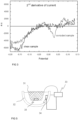
- Figure 6 shows an example of the prepared data mentioned above.
- the prepared data refers to measured current values during the voltage sweep from which the corresponding current values without any object (i.e. empty basket) is removed.
- the measured current values represent an average of three consecutive current measurements.
- Figure 6 also shows a baseline which is a fitted curve from the zero-potential point to point of the minimum potential.
- the minimum potential is selected to be -0,2 Volts and the highest value of voltage is zero. The voltage in the measurement is swept from the negative side to zero to obtain the current values.
- Figure 7 shows a smoothed current curve in which the baseline of Figure 6 is subtracted from the prepared data of Figure 6 .
- the slope of the baseline is calculated and the maximum point of the smoothed curve is determined to obtain data used in the classification.
- Figure 8 shows an example of data that is gathered with known reference objects (with corrosion and without corrosion) together with data from the objects from which the corrosion is tested. Thus the amount of data used in the chart of Figure 8 increases with every scanning procedure carried out.
- the classification to clean or corroded may be carried out using Nearest-Neighbor classification, for example.
- Nearest-Neighbor classification it is checked whether the nearest existing data point in the chart relates to a clean object or to an object having corrosion. As the amount of data in the chart of Figure 8 increases, the classification of the object gets more accurate.
- the detecting of the presence of corrosion comprises determining the current response in a selected potential range. Determining from the current response data used in a machine learning procedure, the machine learning procedure comprising previously gathered data as described above. Further, the embodiment comprises classifying the object to a corroded sample or to a clean sample based on the determined data and from the previously gathered data using machine learning.
- the above-described apparatus is an example of a possible structure with which the detection of corrosion can be carried out.
- the mechanical structure of the apparatus may be different. It is also understandable, that as different objects have different shapes and sizes, the object is not necessarily inspected completely with one procedure or that only a part of an object is inspected. When an object is only partially immersed into an electrolyte, only the immersed portion of the object is inspected. However, when placing the object in the electrolyte in different orientations the complete surface of the object may be inspected using repeated procedures.
Landscapes
- Life Sciences & Earth Sciences (AREA)
- Health & Medical Sciences (AREA)
- Chemical & Material Sciences (AREA)
- Physics & Mathematics (AREA)
- General Health & Medical Sciences (AREA)
- Pathology (AREA)
- Immunology (AREA)
- General Physics & Mathematics (AREA)
- Analytical Chemistry (AREA)
- Biochemistry (AREA)
- Molecular Biology (AREA)
- Biodiversity & Conservation Biology (AREA)
- Ecology (AREA)
- Environmental & Geological Engineering (AREA)
- Environmental Sciences (AREA)
- Chemical Kinetics & Catalysis (AREA)
- Electrochemistry (AREA)
- Engineering & Computer Science (AREA)
- Food Science & Technology (AREA)
- Medicinal Chemistry (AREA)
- Spectroscopy & Molecular Physics (AREA)
- Testing Resistance To Weather, Investigating Materials By Mechanical Methods (AREA)
Description
- The present invention relates to the detection of corrosion, and more particularly to detection of corrosion using electrochemical techniques.
- Corrosion of medical instruments and objects is an everyday phenomenon in hospital environments, for example. It originates, for instance, from residues such as body fluids, which provide an ideal growth substrate for various microbes that might start deteriorating the surface in question through corrosion.
- An essential hygienic step in the cleaning of reusable medical instruments is sterilization by high-temperature steam. However, should the corrosion has already initiated, the instrument needs to be cleaned manually before the sterilization. If not properly cleaned, iron oxides present on the surfaces will contaminate the whole batch of instruments being sterilized.
- The present state-of-art detection of incipient corrosion is based on machine vision, which has several shortcomings. Firstly, many aging objects develop darker passivation layer spots, which give rise to a high number of false positives. Secondly, as any visual means of detection is only capable of evaluating surfaces in the field of view, corrosion in "hidden places" such as hinges of clamps, or in the inner sides of structures, such as stents and tubes, cannot be evaluated reliably with existing techniques.
- In disclosure
US 6264824 B1 corrosion of an object is detected with an electrochemical procedure and more specifically using electrochemical noise measurement. In the disclosure, the corrosion is detected based on corrosion current and the corrosion process is thereby ongoing. - Document
GB 2048294 - Document
CN 10644682 A discloses a method of measuring a current density in hydrogen evaluation though a reinforced steel bar in a reinforced concrete structure. - Document MABBUTT S ET AL: "Review of Artificial Neural Networks (ANN) applied to corrosion monitoring", JOURNAL OF PHYSICS: CONFERENCE SERIES, INSTITUTE OF PHYSICS PUBLISHING, BRISTOL, GB, vol. 364, no. 1, 28 May 2012 (201 2-05-28), page 12114 discloses use of neural networks is identification of localised corrosion by different data analysis routines.
- Document KAMRUNNAHAR M ET AL: "Prediction of corrosion behavior using neural network as a data mining tool", CORROSION SCIENCE, OXFORD, GB, vol. 52, no. 3, 1 March 2010 (2010-03-01), pages 669-677 discusses the use of supervised neural networks in predicting corrosion rate of metal alloys based on data relating to environmental factors and alloy's composition.
- FUSCO MICHAEL A ET AL: "Corrosion of single layer thin film protective coatings on steel substrates for high level waste containers", PROGRESS IN NUCLEAR ENERGY, PERGAMON PRESS, OXFORD, GB, vol. 89, 27 February 2016, pages 159-169, DOI: 10.1016/J.PNUCENE.2016.02.016 discloses a method of detecting corrosion on surfaces of stainless steel samples, the method comprising immersing the object into an electrolyte (NaCl solution) and detecting by electrochemical techniques (cyclic potentiodynamic polarization) the presence of corrosion on the surfaces of the object based on current originating from redox reaction of iron.
- An object of the present invention is to provide a method and an apparatus for implementing the method so as to overcome the above problem relating to detecting corrosion on instruments with complex geometries. The object of the invention is achieved by a method and an apparatus which are characterized by what is stated in the independent claims. The preferred embodiments of the invention are disclosed in the dependent claims.
- The invention is based on the idea of utilization of electrochemical techniques to enable an analysis of all exposed surfaces. The inspected object is immersed in an electrolyte, and a current response can be used for detecting the corrosion. Electrochemical techniques enable to obtain an indication of corrosion even if the corrosion is not visible. Further, with electrochemical techniques, very small amounts of corrosion products on a large non-corroded surface can be detected which would be hard to detect with known methods and devices which are based on visual inspection. Even further, the invention enables to detect corroded surfaces and does not require that the corrosion process is ongoing.
- The method and apparatus of the invention are able to provide accurate results with minimal false-positive results. The method does not react to harmless surface alterations and alerts the user only when the presence of iron oxide species is detected.
- The invention further enables to inspect objects with complex forms without losing the accuracy of the inspection and without harming or destroying the inspected objects as the corrosion current is not flowing. The inspection provides reliable results in connection with non-visible internal structures. The invention can also be applied to various automated quality control processes.
- In the following, the invention will be described in greater detail by means of preferred embodiments with reference to the accompanying drawings, in which
-
Figure 1 shows current waveforms obtained with an embodiment of the invention; -
Figure 2 shows the first derivative of current as a function of potential; -
Figure 3 shows the second derivative of current as a function of potential; -
Figure 4 shows current waveforms obtained with an embodiment of the invention; -
Figure 5 shows a simplified structure of an embodiment of the invention; -
Figure 6 shows another current waveform; -
Figure 7 shows a modification of the current waveform ofFigure 6 ; and -
Figure 8 shows a chart relating to machine learning. - Small patches of iron oxides on the surface of medical implements has been found to be detectable by electrochemical techniques, such as by means of linear sweep voltammetry (LSV) and/or cyclic voltammetry (CV) in a relevant potential window, according to the present invention between -0.35 V and 0.35 V vs Ag/AgCl reference. Linear sweep voltammetry (LSV) and cyclic voltammetry (CV) are procedures that are known as such and are commonly used to study the properties of electrolysis processes.
- In the present invention, the object to be inspected is immersed in an electrolyte and the presence of corrosion products on the surfaces of the object is detected by electrochemical techniques based on the current originating from the redox reaction of iron. The object to be inspected may comprise one or multiple medical instruments, for example. The electrochemical techniques include linear sweep voltammetry (LSV) and cyclic voltammetry (CV). With LSV or CV, a sweeping voltage is provided in an electrode and a current response is detected. Based on the current response it can be concluded whether corrosion has occurred on the surface of the inspected object. The corrosion on the surface of the inspected object may be due to the corrosion process that has brought iron oxides to the surface or the iron oxides may be due to contact with other corroded objects, for example. The presence of corrosion which is detected with the invention does not require that the corrosion process is ongoing as the detection is based on the redox reaction of the iron in iron oxide and more specifically on the electrical current originating from the redox reaction.
- The voltage sweep rate should be selected to be preferably in the range between 5mV/s and 100 mV/s to facilitate identification of the surface reactions, i.e. the presence of iron(oxides). In LSV or CV procedures a sweeping voltage is applied between the electrodes and a current response is measured. As the object or multiple of objects to be inspected which acts as one of the electrodes may have a large surface area, the capacitive current is prevailing. If the inspected object has corrosion, i.e. iron(oxides), the current response to the sweeping voltage displays an alteration of the signal in a certain voltage area. The current is due to the redox conversion between two charge states of iron, the corresponding electron transfer through the external circuit and the ionic charge balancing. More specifically, the two states of iron are Fe2+ and Fe3+, and the detected current is due to the transfer of electrons between these two states.
- By complete immersion of the inspected objects, such as medical tools, medical instruments, clinical research instruments, clinical instruments, components, spare parts, or any metallic pieces, into a suitable electrolyte, contact between the detecting medium and point of corrosion can be ensured as the electrolyte is in connection with the object no matter what the shape of the object is. A suitable electrolyte is, for example, a synthetic physiological fluid which is also known as IV-fluid. In the method, an electrochemical reaction is obtained using a setup, in which the electrolyte is preferably the IV fluid. Further, the inspected objects in the electrolyte are acting as a working electrode and an electrolyte vessel acts as a counter electrode. Further, a reference electrode is provided to complete the required three-electrode setup. The third electrode is an Ag/AgCl reference electrode. Such a reference electrode is suitable as the physiological fluid is used as an electrolyte is sufficiently high in chloride content. Ag/AgCl reference electrode has been found to be a suitable reference electrode. However, other reference electrodes can also be employed without departing from the invention. The use of IV-fluid is also suitable as it is readily available in hospital environments, for example. Further, the properties of the fluid are not harmful to the instruments which are being scanned. Other suitable reference electrodes include calomel electrodes (SCE) and reversible hydrogen electrodes (RHE, SHE), for example. With different electrodes, a different electrolyte may have to be chosen. Further, the potential window in which the voltage change is carried out has to be adjusted according to the selected reference electrode in a known manner. Ag/AgCl reference electrode is used as the electrode is known to be stable and durable in the intended chemical surrounding. The electrolyte used in the invention is preferably a water-based electrolyte having salt (chloride) content. As mentioned, IV-fluid has the properties which are needed for the electrolyte.
- It is important, that the used electrolyte does not react with intact surfaces so that the object from which the corrosion is detected is harmed.
- As mentioned above, in the LSV or CV scan voltage is changed and current between the electrodes is measured. As the corroded surface is typically comparatively small with respect to the non-corroded or intact surface area, the obtained current originating from the electrolysis reaction is small. The current corresponding to the surface alteration being studied is obtained typically in a certain part of the voltage sweep, and the presence of current indicating the corrosion can be detected from the current response.
- According to an embodiment of the invention, the current indicating corrosion is detected from the first or second derivative of the current. The first derivative of the current represents the change rate of current and the second derivative of the current represents the rate of the current change. When a voltage sweep is employed, the resulting current changes approximately linearly, i.e. it increases or decreases without any abrupt changes. This linear change is due to the capacitive current. However, in a certain voltage range, the current has an additional component originating from the redox conversion of iron species if these are present on the surface. This additional current component is indicative of the corrosion of the object. The current peak or an alteration in the current signal is detectable as such or from the first or the second derivative of the current.
Figure 1 shows an example of current as a function of potential both for a clean sample and for a corroded sample. The current peak is hardly visible in the current of the corroded sample ofFigure 1 at 0,25 Volts.Figure 2 shows the derivatives of the currents ofFigure 1 . It can be seen that a peak is more visible and thus more easily detectable in the derivative of the curve than in the original current waveform ofFigure 1. Figure 2 also shows the waveform of the derivative of the clean sample ofFigure 1 . -
Figure 3 further shows the second derivatives of the current response ofFigure 1 . InFigure 3 the second derivatives of both clean sample and corroded sample are shown. As can be seen, a clear and detectable peak is shown in the waveform of the corroded sample. - The detection of current from the redox conversion of iron species can be detected using circuitry in which the current is measured as digital samples or transformed into digital form. The digital representation of the current waveform can be subjected to mathematical calculation or transformations. These calculations may include using different filters for determining whether a current peak is present in the current response. Further, in a preferred embodiment, the first or the second derivative of the current is calculated. As the current is as digital samples, the first derivative and the second derivative of the current can be calculated using a suitable software algorithm. The value of the second derivative of the current can be used as an indication of whether corrosion is detected. It is, however, clear that the current originating from the redox reaction can be detected using other means which are able to analyse the current signal. The first or the second derivatives of the current can be determined with respect to time or potential.
-
Figure 4 shows voltammograms which were obtained when the method of the invention was tested. The upper plot shows measurements which were carried out with corroded test pieces and the lower plot shows similar measurements with test pieces in which the surface is free of corrosion. The potential window in the tests is selected to be from -0,3V to 0,3V. It can be seen that upper plot with the corroded test piece shows an increase in the current when the sweeping voltage reaches approximately 0,18V. Further, a negative peak is visible when the voltage speed is negative at voltages -0,05V. When the voltage increases the positive current peak is due to oxidation of the iron and the negative current peak is due to reduction of the iron. As seen from the lower plot, the pieces which were not corroded did not show a current peak when tested according to the method. - In the method, the potential window used for the potential sweep can be selected to be from 0 V to 0.35V vs Ag/AgCl reference. Once potential is changed between these values, a current peak is obtained in the current response if corrosion is present. As described above, the current peak is positive and it is obtained when the current is increased.
- It has been found out, that in the present method the negative peak due to the reduction of the iron can be detected more clearly than the positive peak. According to an embodiment, the detection of the iron oxides is carried out from the current when the voltage is reduced. Further, in an embodiment, the potential window in which the potential is changed is selected to be -0,25V to 0,1V with the
- Ag/AgCl reference electrode. As mentioned above, when other reference electrodes are used, the potential window is changed accordingly. The negative peak or the positive peak refer generally to alteration in the current signal. The alteration in the current signal may detected also with other signal processing procedures than by detecting the peaks. Generally, the change of the current signal with respect to a clean sample may indicate the presence of iron oxides.
- The potential window and the sweep rate are selected in such a manner, that the objects which are under inspection are not harmed. If, for example, the sweep rate is too high the current response associated with iron oxide alteration may go unnoticed, and if the potential window is too wide, the intact surfaces might get damaged. Thus the potential window and the sweep rate are preferably selected in such a manner, that the associated response is obtained only from a corroded surface, i.e. only when iron oxides are present.
- Further, the number of the sweeps, that is the increase and decrease of potential, can have a selected maximum amount. Once a positive indication is found, the process is stopped. If a positive or uncertain indication is obtained, the sweeps are repeated for the set number of times at the maximum. Thus according to an embodiment, the measurement cycle, i.e. the voltage sweep, is repeated. The repeated measurement may be used for ensuring the correctness of the results.
- The apparatus of the invention, which implements the method, comprises means for immersing the object into electrolyte and means for detecting by electrochemical techniques the presence of corrosion on the surfaces of the object based on current originating from redox reaction of iron.
-
Figure 5 shows an example of an apparatus for implementing the method. According to an embodiment of the invention, the means for immersing theobject 35 comprise a stainless steel member to which the objects to be inspected are connected electrically. The stainless steel member is preferably a stainless steel plate or a stainlesssteel mesh basket 31 in which the object or objects can be placed. The stainless steel member is electrically connected to themeasurement circuitry 33 and theobject 35 forms the working electrode of the system. The object is immersed into an electrolyte which is preferably held in astainless steel vessel 32. Thestainless steel vessel 32 acts as a counter electrode and is also connected to themeasurement circuitry 33. The setup also comprises areference electrode 34, which is an Ag/AgCl reference electrode. - The means for detecting the presence of corrosion products comprise the measurement circuitry, which provides a pre-programmed LSV or CV scan. The dedicated measurement circuitry displays the functionality required to produce the LSV or CV scan at an accuracy and sensitivity sufficient for the detection process. For example, the accuracy of the voltage control should be better than 10mV, the accuracy of the sweep rate should better than 2mV/s and the sensitivity of the current measurement should be better than 1µA. The accuracy of control and the sensitivity of the measurement allow detecting the current response reliably.
- In addition to the measurement circuitry providing the scan, an embedded software algorithm or software installed on an external unit compares the obtained results, i.e. the current response, against a given set of criteria. For example, the comparison may compare the first or second derivative of the current in a specific potential window against a limit value. If the first or second derivative of the current exceeds the limit value, the measurement software produces an indication that the object has iron oxide on its surface (corrosion). On the other hand, if the second derivative of the current remains below the set limit value, the measurement circuitry produces an indication that corrosion was not found.
- This information may be conveyed to the user simply by using suitable light indications and/or text information on a display visible to the user of the apparatus. Once the scan has ended, the user of the apparatus can remove the objects and proceed with them according to the obtained results.
- In one aspect of the disclosure, machine learning is employed in detecting corrosion. Specifically supervised learning is employed in teaching the machine learning process. The procedure in the machine learning process comprises measuring and storing the current response for a selected voltage sweep.
- The measuring and storing current response for a selected voltage sweep is carried out without the object. Thus only the used basket or similar is employed in a sweep. In the next step, the stored current response of the voltage sweep without the object is removed from the stored current response with the object. The stored current response with the object may be an average of multiple current responses with the same object. The above removal of current response may be carried out simply by subtracting the current values for obtaining prepared data.
- Further, in the procedure relating to machine learning, a linear baseline is fitted to the prepared data from a certain potential point to a point of the certain minimum potential point. Further, the baseline is subtracted from the prepared data, and the remaining data is smoothed or filtered using a moving average filter, for example.
- In the procedure, the slope of the baseline and the maximum point of the smoothed data are determined and stored. The slope and the maximum point are used as the data relating to machine learning. Each measurement is thus classified in a two-dimensional manner.
- As supervised machine learning is employed, objects having corrosion on the surface and cleans objects are employed in the above procedure to obtain data which is used as a reference classification. Once classification data is gathered with the procedure, the procedure is used to determine whether the object has corrosion on its surface or the object is free from corrosion. The data obtained with the above procedure from actual samples are mapped with the reference data. Using the reference data the data obtained from the sample is classified with a classification method, such as a Nearest-Neighbor classification.
- In the above procedure, the current samples are obtained using the measurement of the invention, i.e. current is measured using electrochemical techniques, such as LSV or CV.
- The above machine learning procedure is further described in connection with
Figures 6, 7 , and8 which show examples of obtained data in visualized form.Figure 6 shows an example of the prepared data mentioned above. The prepared data refers to measured current values during the voltage sweep from which the corresponding current values without any object (i.e. empty basket) is removed. The measured current values represent an average of three consecutive current measurements. -
Figure 6 also shows a baseline which is a fitted curve from the zero-potential point to point of the minimum potential. In the example shown inFigure 6 , the minimum potential is selected to be -0,2 Volts and the highest value of voltage is zero. The voltage in the measurement is swept from the negative side to zero to obtain the current values. - Further,
Figure 7 shows a smoothed current curve in which the baseline ofFigure 6 is subtracted from the prepared data ofFigure 6 . The slope of the baseline is calculated and the maximum point of the smoothed curve is determined to obtain data used in the classification.Figure 8 shows an example of data that is gathered with known reference objects (with corrosion and without corrosion) together with data from the objects from which the corrosion is tested. Thus the amount of data used in the chart ofFigure 8 increases with every scanning procedure carried out. - As actual measurement data is placed in the chart, a certain procedure for determining whether the object to which the measurement data relates is clean or has experienced corrosion. The classification to clean or corroded may be carried out using Nearest-Neighbor classification, for example. In Nearest-Neighbor classification it is checked whether the nearest existing data point in the chart relates to a clean object or to an object having corrosion. As the amount of data in the chart of
Figure 8 increases, the classification of the object gets more accurate. - Thus according to an embodiment, the detecting of the presence of corrosion comprises determining the current response in a selected potential range. Determining from the current response data used in a machine learning procedure, the machine learning procedure comprising previously gathered data as described above. Further, the embodiment comprises classifying the object to a corroded sample or to a clean sample based on the determined data and from the previously gathered data using machine learning.
- The above-described apparatus is an example of a possible structure with which the detection of corrosion can be carried out. Depending on the size of the object the mechanical structure of the apparatus may be different. It is also understandable, that as different objects have different shapes and sizes, the object is not necessarily inspected completely with one procedure or that only a part of an object is inspected. When an object is only partially immersed into an electrolyte, only the immersed portion of the object is inspected. However, when placing the object in the electrolyte in different orientations the complete surface of the object may be inspected using repeated procedures.
- It will be obvious to a person skilled in the art that, as technology advances, the inventive concept can be implemented in various ways. The invention and its embodiments are not limited to the examples described above but may vary within the scope of the claims.
Claims (13)
- A method of detecting corrosion on surfaces of an object (35), the method comprisingimmersing the object (35) into an electrolyte,detecting by electrochemical techniques the presence of corrosion on the surfaces of the object (35), wherein the step of detecting comprises using linear sweep voltammetry (LSV) or cyclic voltammetry (CV) scan and using an Ag or an AgCl reference electrode in the LSV or CV scan as the third electrode, and characterised in that detecting presence of corrosion is based on current originating from redox reaction of iron and the potential window for the LSVor CV scan is between -0.35V and 0.35V vs Ag/AgCl reference.
- A method according to claim 1, characterised in that the LSV or CV scan is used to detect the presence of iron(oxides).
- A method according to claim 1 or 2, characterised in that the object (35) is of stainless steel alloy and acts as a working electrode.
- A method according to claim 1 to 3, characterised in that the sweep rate of LSV or CV scan is in the range between 5mV/s and 100 mV/s.
- A method according to claim 1 to 4, characterised in that the potential window for the LCV or CV scan is between 0V and 0.35V vs Ag/AgCl reference or preferably between -0,25V and 0,1V vs Ag/AgCl reference.
- A method according to claim 1 to 5, characterised in that detecting the presence of corrosion comprises detecting a pattern in a current response obtained with LSV or CV scan.
- A method according to claim 1 to 6, characterised in that detecting the presence of corrosion comprises detecting the rate of a current change or the change of the rate of current change, the current being the current response obtained with LSV or CV scan.
- A method according to claim 7, characterised in that the rate of the current change is the derivative of the current with respect to time or with respect to potential, the current being the current response to the LSV or CV scan.
- A method according to claim 7, characterised in that the change of the rate of the current change is the second derivative of the current with respect to time or with respect to potential, the current being the current response to the LSV or CV scan.
- A method according to any one of the previous claims 1 to 9, characterised in that the electrolyte is a synthetic physiological fluid.
- A method according to any one of the previous claims 1 to 10, characterised in that the object (35) is a medical object, such as a medical instrument, clinical instrument or clinical research instrument.
- A method according to any one of the previous claims 1 to 6, characterised in that detecting the presence of corrosion comprisesdetermining the current response in a selected potential range, determining from the current response data used in a machine learning procedure, the machine learning procedure comprising previously gathered data,classifying the object to a corroded sample or to a clean sample based on the determined data and from the previously gathered data using machine learning.
- An apparatus for detecting corrosion on surfaces of an object comprisingmeans for immersing the object (35) into an electrolyte,configured to perform the step of detecting by electrochemical techniques the presence of corrosion on the surfaces of the object (35) wherein the step of detecting comprises using linear sweep voltammetry (LSV) or cyclic voltammetry (CV) scan and using an Ag or an AgCl reference electrode in the LSV or CV scan as the third electrode, and characterised in that detecting presence of corrosion is based on current originating from redox reaction of iron and the potential window for the LSVor CV scan is between -0.35V and 0.35V vs Ag/AgCl reference.
Applications Claiming Priority (2)
| Application Number | Priority Date | Filing Date | Title |
|---|---|---|---|
| FI20196024A FI20196024A1 (en) | 2019-11-27 | 2019-11-27 | Method and device for detecting corrosion |
| PCT/FI2020/050796 WO2021105563A1 (en) | 2019-11-27 | 2020-11-25 | Method and apparatus for detecting corrosion |
Publications (3)
| Publication Number | Publication Date |
|---|---|
| EP4065953A1 EP4065953A1 (en) | 2022-10-05 |
| EP4065953C0 EP4065953C0 (en) | 2025-01-22 |
| EP4065953B1 true EP4065953B1 (en) | 2025-01-22 |
Family
ID=73740424
Family Applications (1)
| Application Number | Title | Priority Date | Filing Date |
|---|---|---|---|
| EP20820472.7A Active EP4065953B1 (en) | 2019-11-27 | 2020-11-25 | Method and apparatus for detecting corrosion |
Country Status (6)
| Country | Link |
|---|---|
| US (1) | US11953422B2 (en) |
| EP (1) | EP4065953B1 (en) |
| JP (1) | JP7469827B2 (en) |
| KR (1) | KR102810045B1 (en) |
| FI (1) | FI20196024A1 (en) |
| WO (1) | WO2021105563A1 (en) |
Families Citing this family (1)
| Publication number | Priority date | Publication date | Assignee | Title |
|---|---|---|---|---|
| JP7854415B2 (en) * | 2023-04-17 | 2026-05-01 | Jfeテクノリサーチ株式会社 | Electrochemical measuring device and electrochemical measuring method for metallic materials |
Citations (1)
| Publication number | Priority date | Publication date | Assignee | Title |
|---|---|---|---|---|
| US5859537A (en) * | 1996-10-03 | 1999-01-12 | Dacco Sci, Inc. | Electrochemical sensors for evaluating corrosion and adhesion on painted metal structures |
Family Cites Families (19)
| Publication number | Priority date | Publication date | Assignee | Title |
|---|---|---|---|---|
| JPS55149049A (en) | 1979-05-10 | 1980-11-20 | Nippon Paint Co Ltd | Testing method for corrosion evaluation of coated metal material and its apparatus |
| GB2048491B (en) | 1980-03-17 | 1983-08-03 | Nippon Paint Co Ltd | Method for evaluating corrosion of coated metallic material |
| JPH0484754A (en) * | 1990-07-27 | 1992-03-18 | Hitachi Ltd | Material integrity evaluation method |
| US5795461A (en) | 1996-03-26 | 1998-08-18 | Rising; Brandt A. | Electrode system for monitoring corrosion |
| US6264824B1 (en) | 1998-02-20 | 2001-07-24 | Integriti Investments Ltd. | Assessment of corrosion |
| JP2001033389A (en) | 1999-07-26 | 2001-02-09 | Sumitomo Metal Ind Ltd | Method and apparatus for evaluating corrosion resistance of steel |
| JP3730157B2 (en) | 2001-11-13 | 2005-12-21 | 独立行政法人科学技術振興機構 | Method for evaluating the stability of surface protective coatings on metallic materials |
| CN1916617B (en) | 2005-08-19 | 2011-11-16 | 深圳富泰宏精密工业有限公司 | Method for measuring density of corrosion inhibitor |
| US20070163892A1 (en) | 2006-01-17 | 2007-07-19 | Honeywell International, Inc. | Corrosion sensor |
| US20080179198A1 (en) | 2007-01-29 | 2008-07-31 | Burgess Michelle S | System and method of use for electrochemical measurement of corrosion |
| US7719292B2 (en) | 2007-10-12 | 2010-05-18 | Honeywell International Inc. | Method and apparatus for electrochemical corrosion monitoring |
| EP2310834A2 (en) | 2008-07-02 | 2011-04-20 | Pepperl & Fuchs, Inc. | Electrochemical noise as a localized corrosion indicator |
| US8926823B2 (en) * | 2010-11-30 | 2015-01-06 | Georges J. Kipouros | Sub-coating coated metal corrosion measurement |
| JP2012233819A (en) | 2011-05-06 | 2012-11-29 | Yokogawa Electric Corp | Metal characteristics measuring device |
| KR20150068206A (en) * | 2013-12-11 | 2015-06-19 | (주) 테크로스 | Apparatus for measuring water quality |
| US9354157B2 (en) | 2013-12-30 | 2016-05-31 | Electric Power Research Institute, Inc. | Apparatus and method for assessing subgrade corrosion |
| US10001436B2 (en) | 2014-01-22 | 2018-06-19 | Southwest Research Institute | In-situ measurement of corrosion in buried pipelines using vertically measured pipe-to-soil potential |
| CN106442682B (en) * | 2016-08-31 | 2019-06-14 | 浙江大学 | A method for measuring the critical current density of hydrogen evolution of steel bars in reinforced concrete structures |
| US20190204210A1 (en) * | 2016-09-06 | 2019-07-04 | Arizona Board Of Regents On Behalf Of The University Of Arizona | Electrochemical Detection of Corrosion and Corrosion Rates of Metal in Molten Salts at High Temperatures |
-
2019
- 2019-11-27 FI FI20196024A patent/FI20196024A1/en unknown
-
2020
- 2020-11-25 JP JP2022531004A patent/JP7469827B2/en active Active
- 2020-11-25 EP EP20820472.7A patent/EP4065953B1/en active Active
- 2020-11-25 US US17/779,822 patent/US11953422B2/en active Active
- 2020-11-25 WO PCT/FI2020/050796 patent/WO2021105563A1/en not_active Ceased
- 2020-11-25 KR KR1020227021839A patent/KR102810045B1/en active Active
Patent Citations (1)
| Publication number | Priority date | Publication date | Assignee | Title |
|---|---|---|---|---|
| US5859537A (en) * | 1996-10-03 | 1999-01-12 | Dacco Sci, Inc. | Electrochemical sensors for evaluating corrosion and adhesion on painted metal structures |
Also Published As
| Publication number | Publication date |
|---|---|
| US20230011245A1 (en) | 2023-01-12 |
| EP4065953C0 (en) | 2025-01-22 |
| JP7469827B2 (en) | 2024-04-17 |
| WO2021105563A1 (en) | 2021-06-03 |
| KR102810045B1 (en) | 2025-05-21 |
| JP2023504062A (en) | 2023-02-01 |
| KR20220147574A (en) | 2022-11-03 |
| EP4065953A1 (en) | 2022-10-05 |
| FI20196024A1 (en) | 2021-05-28 |
| US11953422B2 (en) | 2024-04-09 |
Similar Documents
| Publication | Publication Date | Title |
|---|---|---|
| CA2353946C (en) | Electrochemical noise technique for corrosion | |
| US6015484A (en) | Detection of pitting corrosion | |
| US7686938B2 (en) | Quantitative, real time measurements of localized corrosion events | |
| Katemann et al. | Precursor sites for localised corrosion on lacquered tinplates visualised by means of alternating current scanning electrochemical microscopy | |
| US7309414B2 (en) | Method for measuring localized corrosion rate with a multi-electrode array sensor | |
| Mansfeld | Electrochemical methods of corrosion testing | |
| Aslam | Potentiodynamic polarization methods for corrosion measurement | |
| WO1998050786A1 (en) | An in-situ process for the monitoring of localized pitting corrosion | |
| US4155814A (en) | Method and apparatus for galvanostatic and potentiostatic electrochemical investigation of the rate of corrosion processes | |
| US7713405B2 (en) | Quantitative transient analysis of localized corrosion | |
| WO2009094408A1 (en) | Localized corrosion monitoring device for limited conductivity fluids | |
| Cui et al. | Use of scanning reference electrode technique for characterizing pitting and general corrosion of carbon steel in neutral media | |
| Chen et al. | Determining tribocorrosion rate and wear-corrosion synergy of bulk and thin film aluminum alloys | |
| Zheng et al. | Identifying defect size in organic coatings by electrochemical noise, galvanostatic step and potentiostatic step techniques | |
| Tan | An overview of techniques for characterizing inhomogeneities in organic surface films and underfilm localized corrosion | |
| Scully et al. | Methods for determining aqueous corrosion reaction rates | |
| US11953422B2 (en) | Method and apparatus for detecting corrosion | |
| Scully¹ | Electrochemical tests | |
| Kearns et al. | ASTM standardization of electrochemical noise measurement | |
| US4455212A (en) | Gel electrode for early detection of metal fatigue | |
| Lillard et al. | Scanning electrode techniques for investigating near-surface solution current densities | |
| Thunberg et al. | The role of patina on archaeological copper alloy coins in the outbreak and progression of bronze disease | |
| Ajayan et al. | Coating Characterization with Electrochemical Techniques | |
| SU1409896A1 (en) | Method of determining comparative resistance of corrosion-resistant steels to pitting corrosion | |
| Leeds | Electrochemical Noise to Monitor Corrosion of a Coated Metal |
Legal Events
| Date | Code | Title | Description |
|---|---|---|---|
| STAA | Information on the status of an ep patent application or granted ep patent |
Free format text: STATUS: UNKNOWN |
|
| STAA | Information on the status of an ep patent application or granted ep patent |
Free format text: STATUS: THE INTERNATIONAL PUBLICATION HAS BEEN MADE |
|
| PUAI | Public reference made under article 153(3) epc to a published international application that has entered the european phase |
Free format text: ORIGINAL CODE: 0009012 |
|
| STAA | Information on the status of an ep patent application or granted ep patent |
Free format text: STATUS: REQUEST FOR EXAMINATION WAS MADE |
|
| 17P | Request for examination filed |
Effective date: 20220621 |
|
| AK | Designated contracting states |
Kind code of ref document: A1 Designated state(s): AL AT BE BG CH CY CZ DE DK EE ES FI FR GB GR HR HU IE IS IT LI LT LU LV MC MK MT NL NO PL PT RO RS SE SI SK SM TR |
|
| DAV | Request for validation of the european patent (deleted) | ||
| DAX | Request for extension of the european patent (deleted) | ||
| GRAP | Despatch of communication of intention to grant a patent |
Free format text: ORIGINAL CODE: EPIDOSNIGR1 |
|
| STAA | Information on the status of an ep patent application or granted ep patent |
Free format text: STATUS: GRANT OF PATENT IS INTENDED |
|
| INTG | Intention to grant announced |
Effective date: 20240830 |
|
| GRAS | Grant fee paid |
Free format text: ORIGINAL CODE: EPIDOSNIGR3 |
|
| GRAA | (expected) grant |
Free format text: ORIGINAL CODE: 0009210 |
|
| STAA | Information on the status of an ep patent application or granted ep patent |
Free format text: STATUS: THE PATENT HAS BEEN GRANTED |
|
| AK | Designated contracting states |
Kind code of ref document: B1 Designated state(s): AL AT BE BG CH CY CZ DE DK EE ES FI FR GB GR HR HU IE IS IT LI LT LU LV MC MK MT NL NO PL PT RO RS SE SI SK SM TR |
|
| REG | Reference to a national code |
Ref country code: GB Ref legal event code: FG4D |
|
| REG | Reference to a national code |
Ref country code: CH Ref legal event code: EP |
|
| REG | Reference to a national code |
Ref country code: IE Ref legal event code: FG4D |
|
| REG | Reference to a national code |
Ref country code: DE Ref legal event code: R096 Ref document number: 602020045251 Country of ref document: DE |
|
| U01 | Request for unitary effect filed |
Effective date: 20250210 |
|
| U07 | Unitary effect registered |
Designated state(s): AT BE BG DE DK EE FI FR IT LT LU LV MT NL PT RO SE SI Effective date: 20250214 |
|
| PG25 | Lapsed in a contracting state [announced via postgrant information from national office to epo] |
Ref country code: RS Free format text: LAPSE BECAUSE OF FAILURE TO SUBMIT A TRANSLATION OF THE DESCRIPTION OR TO PAY THE FEE WITHIN THE PRESCRIBED TIME-LIMIT Effective date: 20250422 |
|
| PG25 | Lapsed in a contracting state [announced via postgrant information from national office to epo] |
Ref country code: PL Free format text: LAPSE BECAUSE OF FAILURE TO SUBMIT A TRANSLATION OF THE DESCRIPTION OR TO PAY THE FEE WITHIN THE PRESCRIBED TIME-LIMIT Effective date: 20250122 |
|
| PG25 | Lapsed in a contracting state [announced via postgrant information from national office to epo] |
Ref country code: ES Free format text: LAPSE BECAUSE OF FAILURE TO SUBMIT A TRANSLATION OF THE DESCRIPTION OR TO PAY THE FEE WITHIN THE PRESCRIBED TIME-LIMIT Effective date: 20250122 |
|
| PG25 | Lapsed in a contracting state [announced via postgrant information from national office to epo] |
Ref country code: IS Free format text: LAPSE BECAUSE OF FAILURE TO SUBMIT A TRANSLATION OF THE DESCRIPTION OR TO PAY THE FEE WITHIN THE PRESCRIBED TIME-LIMIT Effective date: 20250522 |
|
| PG25 | Lapsed in a contracting state [announced via postgrant information from national office to epo] |
Ref country code: HR Free format text: LAPSE BECAUSE OF FAILURE TO SUBMIT A TRANSLATION OF THE DESCRIPTION OR TO PAY THE FEE WITHIN THE PRESCRIBED TIME-LIMIT Effective date: 20250122 |
|
| PG25 | Lapsed in a contracting state [announced via postgrant information from national office to epo] |
Ref country code: GR Free format text: LAPSE BECAUSE OF FAILURE TO SUBMIT A TRANSLATION OF THE DESCRIPTION OR TO PAY THE FEE WITHIN THE PRESCRIBED TIME-LIMIT Effective date: 20250423 |
|
| PG25 | Lapsed in a contracting state [announced via postgrant information from national office to epo] |
Ref country code: SM Free format text: LAPSE BECAUSE OF FAILURE TO SUBMIT A TRANSLATION OF THE DESCRIPTION OR TO PAY THE FEE WITHIN THE PRESCRIBED TIME-LIMIT Effective date: 20250122 |
|
| PG25 | Lapsed in a contracting state [announced via postgrant information from national office to epo] |
Ref country code: CZ Free format text: LAPSE BECAUSE OF FAILURE TO SUBMIT A TRANSLATION OF THE DESCRIPTION OR TO PAY THE FEE WITHIN THE PRESCRIBED TIME-LIMIT Effective date: 20250122 |
|
| PG25 | Lapsed in a contracting state [announced via postgrant information from national office to epo] |
Ref country code: SK Free format text: LAPSE BECAUSE OF FAILURE TO SUBMIT A TRANSLATION OF THE DESCRIPTION OR TO PAY THE FEE WITHIN THE PRESCRIBED TIME-LIMIT Effective date: 20250122 |
|
| PLBE | No opposition filed within time limit |
Free format text: ORIGINAL CODE: 0009261 |
|
| STAA | Information on the status of an ep patent application or granted ep patent |
Free format text: STATUS: NO OPPOSITION FILED WITHIN TIME LIMIT |
|
| U20 | Renewal fee for the european patent with unitary effect paid |
Year of fee payment: 6 Effective date: 20251117 |
|
| 26N | No opposition filed |
Effective date: 20251023 |
|
| PGFP | Annual fee paid to national office [announced via postgrant information from national office to epo] |
Ref country code: GB Payment date: 20251117 Year of fee payment: 6 |
|
| PGFP | Annual fee paid to national office [announced via postgrant information from national office to epo] |
Ref country code: NO Payment date: 20251120 Year of fee payment: 6 |