EP4065846B1 - Locking assembly for a fluid end of a high pressure pump - Google Patents
Locking assembly for a fluid end of a high pressure pump Download PDFInfo
- Publication number
- EP4065846B1 EP4065846B1 EP21707846.8A EP21707846A EP4065846B1 EP 4065846 B1 EP4065846 B1 EP 4065846B1 EP 21707846 A EP21707846 A EP 21707846A EP 4065846 B1 EP4065846 B1 EP 4065846B1
- Authority
- EP
- European Patent Office
- Prior art keywords
- actuator
- wedges
- locking assembly
- fluid end
- lock ring
- Prior art date
- Legal status (The legal status is an assumption and is not a legal conclusion. Google has not performed a legal analysis and makes no representation as to the accuracy of the status listed.)
- Active
Links
Images












Classifications
-
- F—MECHANICAL ENGINEERING; LIGHTING; HEATING; WEAPONS; BLASTING
- F04—POSITIVE - DISPLACEMENT MACHINES FOR LIQUIDS; PUMPS FOR LIQUIDS OR ELASTIC FLUIDS
- F04B—POSITIVE-DISPLACEMENT MACHINES FOR LIQUIDS; PUMPS
- F04B53/00—Component parts, details or accessories not provided for in, or of interest apart from, groups F04B1/00 - F04B23/00 or F04B39/00 - F04B47/00
- F04B53/10—Valves; Arrangement of valves
-
- F—MECHANICAL ENGINEERING; LIGHTING; HEATING; WEAPONS; BLASTING
- F04—POSITIVE - DISPLACEMENT MACHINES FOR LIQUIDS; PUMPS FOR LIQUIDS OR ELASTIC FLUIDS
- F04B—POSITIVE-DISPLACEMENT MACHINES FOR LIQUIDS; PUMPS
- F04B53/00—Component parts, details or accessories not provided for in, or of interest apart from, groups F04B1/00 - F04B23/00 or F04B39/00 - F04B47/00
- F04B53/16—Casings; Cylinders; Cylinder liners or heads; Fluid connections
-
- F—MECHANICAL ENGINEERING; LIGHTING; HEATING; WEAPONS; BLASTING
- F04—POSITIVE - DISPLACEMENT MACHINES FOR LIQUIDS; PUMPS FOR LIQUIDS OR ELASTIC FLUIDS
- F04B—POSITIVE-DISPLACEMENT MACHINES FOR LIQUIDS; PUMPS
- F04B53/00—Component parts, details or accessories not provided for in, or of interest apart from, groups F04B1/00 - F04B23/00 or F04B39/00 - F04B47/00
- F04B53/22—Arrangements for enabling ready assembly or disassembly
-
- F—MECHANICAL ENGINEERING; LIGHTING; HEATING; WEAPONS; BLASTING
- F16—ENGINEERING ELEMENTS AND UNITS; GENERAL MEASURES FOR PRODUCING AND MAINTAINING EFFECTIVE FUNCTIONING OF MACHINES OR INSTALLATIONS; THERMAL INSULATION IN GENERAL
- F16K—VALVES; TAPS; COCKS; ACTUATING-FLOATS; DEVICES FOR VENTING OR AERATING
- F16K1/00—Lift valves or globe valves, i.e. cut-off apparatus with closure members having at least a component of their opening and closing motion perpendicular to the closing faces
- F16K1/32—Details
-
- F—MECHANICAL ENGINEERING; LIGHTING; HEATING; WEAPONS; BLASTING
- F16—ENGINEERING ELEMENTS AND UNITS; GENERAL MEASURES FOR PRODUCING AND MAINTAINING EFFECTIVE FUNCTIONING OF MACHINES OR INSTALLATIONS; THERMAL INSULATION IN GENERAL
- F16K—VALVES; TAPS; COCKS; ACTUATING-FLOATS; DEVICES FOR VENTING OR AERATING
- F16K27/00—Construction of housing; Use of materials therefor
- F16K27/12—Covers for housings
-
- F—MECHANICAL ENGINEERING; LIGHTING; HEATING; WEAPONS; BLASTING
- F16—ENGINEERING ELEMENTS AND UNITS; GENERAL MEASURES FOR PRODUCING AND MAINTAINING EFFECTIVE FUNCTIONING OF MACHINES OR INSTALLATIONS; THERMAL INSULATION IN GENERAL
- F16K—VALVES; TAPS; COCKS; ACTUATING-FLOATS; DEVICES FOR VENTING OR AERATING
- F16K35/00—Means to prevent accidental or unauthorised actuation
-
- F—MECHANICAL ENGINEERING; LIGHTING; HEATING; WEAPONS; BLASTING
- F16—ENGINEERING ELEMENTS AND UNITS; GENERAL MEASURES FOR PRODUCING AND MAINTAINING EFFECTIVE FUNCTIONING OF MACHINES OR INSTALLATIONS; THERMAL INSULATION IN GENERAL
- F16K—VALVES; TAPS; COCKS; ACTUATING-FLOATS; DEVICES FOR VENTING OR AERATING
- F16K41/00—Spindle sealings
- F16K41/02—Spindle sealings with stuffing-box ; Sealing rings
Definitions
- Covers may be used on fluid ends in the oil and gas industry, for example on fluid ends of frac pumps or mud pumps. Covers can back out of fluid ends, for example from high pressure operation of the fluid ends. Attempts to lock these covers carry extra parts, reduced efficiencies, increased operational times, complex design and operation, and increased costs.
- US-2017/089334 A1 discloses a locking assembly for a pump or fluid end. The described locking assembly is adapted to couple to a fluid end proximal to a valve cover opening, and includes an insert comprising a plurality of segments, and a cone adapted to be at least partially disposed within an opening in the insert.
- a locking assembly for fluid ends includes a first actuator, the first actuator including one or more coupling surfaces.
- the locking assembly also includes a second actuator disposed at least partially below the first actuator.
- the second actuator includes a body, the body including one or more tapered interfacing surfaces.
- the second actuator also includes one or more coupling surfaces disposed in coupling engagement with the one or more coupling surfaces of the first actuator, and a center axis extending in a longitudinal direction through the body, where the one or more tapered interfacing surfaces taper inward at an angle relative to the center axis.
- the locking assembly also includes a plurality of wedges disposed about the second actuator and movable between an unlocked position and a locked position.
- Each wedge of the plurality of wedges includes a set of one or more external locking surfaces, and a set of one or more tapered interfacing surfaces, where the one or more tapered interfacing surfaces of each wedge is configured to engage with one of the one or more tapered interfacing surfaces of the second actuator.
- the locking assembly also includes a lock ring disposed about the plurality of wedges.
- the lock ring includes a set of one or more internal locking surfaces configured to engage with the external locking surfaces of each wedge of the plurality of wedges.
- the body of the second actuator comprises a plurality of guide blocks; and each wedge of the plurality of wedges comprises a guide slot formed in a respective tapered interfacing surface of the set of one or more tapered interfacing surfaces of the respective wedge, and each guide slot includes a guide block of the plurality of guide blocks disposed at least partially in the respective guide slot.
- aspects of the disclosure relate to locking assembly apparatus and methods for fluid ends, and associated components thereof.
- the present disclosure relates to locking assembly apparatus and methods for a valve cover disposed in an opening of a fluid end.
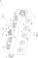
- Figure 1 is a schematic isometric partial view of a fluid end 100 having a fluid end body 105 and a locking assembly 240 in a locked position, according to one implementation.
- the fluid end 100 includes a plurality of bores 110A-110D (bores 110A, bores 110B, and bores 110D are shown in Figure 2A ) formed in the side of the fluid end body 105.
- the fluid end 100 illustrated includes a plurality of retainer nuts 115 disposed in each of the bores 110C.
- the fluid end 100 is adapted to couple to a power end 112 via a pony rod 114.
- the fluid end 100 includes a plurality of valve covers 116. Each valve cover 116 is disposed at least partially in an opening 201 formed in the top of the fluid end body 105. The openings 201 are at least part of the bores 110B. Four valve covers 116 are shown exposed along the top of the fluid end body 105. The center valve cover 116 is secured to the fluid end body 105 by the locking assembly 240.
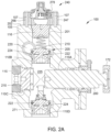
- Figure 2A is a schematic cross-sectional view of the fluid end 100 illustrated in Figure 1 along lines 2A-2A, according to one implementation. Bores 110A, 110B, 110C, and 110D are shown Figure 2A .
- a plunger 200 is shown disposed in the bore 110A, and a valve assembly 205 having a spring 210 is shown disposed in the bore 110B.
- a suction cover 215 is shown disposed in the bore 110C, and a suction valve assembly 271 is shown in the bore 110D.
- the suction cover 215 is disposed inwards of the retainer nut 115 relative to the fluid end body 105.
- the valve cover 116 is a discharge cover.
- a valve body 222 as well as a valve seat 224 may also be disposed in the bores 110B and 110D.
- the fluid end body 105 may also include a discharge manifold 220 formed therein that is in selective communication with at least the bore 110B.
- the bores 110A-110D formed in the fluid end body 105 intersect within the fluid end body 105 at a junction 225.
- each of the suction covers 215 may be replaced with a cover similar to the valve covers 116, and/or the retainer nuts 115 may be replaced with a locking assembly similar to the locking assembly 240.
- the locking assembly 240 is coupled to the fluid end body 105 by a plurality of bolts 107 that are disposed through a plurality of openings 266 formed in a lock ring 247 and threaded into the fluid end body 105.
- a bolt 107 is disposed through each opening 266 to fasten the lock ring 247 to the fluid end body 105 and mount the lock ring 247 to an exterior surface 202 of the fluid end body 105.
- the lock ring 247 is disposed about the plurality of wedges 243.
- the lock ring 247 is a flange.
- the lock ring 247 includes an outer surface 276 and an inner surface 277.
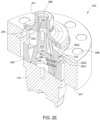
- Figure 2B is a schematic enlarged cross-sectional isometric view of the locking assembly 240 in a locked position, according to one implementation.
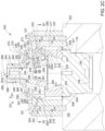
- Figure 2C is a schematic enlarged cross-sectional side view of the locking assembly 240 in the locked position, according to one implementation.
- the locking assembly 240 includes a first actuator 241, a second actuator 242 at least partially disposed within a central opening 269 of the first actuator 241, and a plurality of wedges 243 that are each coupled to the first actuator 241.
- the second actuator 242 is disposed at least partially below the first actuator 241 in the implementations shown in Figures 2B and 2C .
- the second actuator 242 includes and the shaft portion 281 that protrudes upwardly from the body portion 280 in a longitudinal direction D1, and the shaft portion 281 includes the one or more coupling surfaces 285.
- the present disclosure contemplates that the longitudinal direction D1 may be disposed vertically, horizontally, perpendicularly, or at an oblique angle relative to gravitational forces, or in other orientations, all depending on the orientation of the fluid end body 105.
- the longitudinal direction D1 extends upward and away from the fluid end body 105, and away from the fluid end opening 201.
- the body portion 280 includes one or more tapered interfacing surfaces 261 and may include a recessed surface 282 formed in a lower surface 283 of the body portion 280.
- the second actuator 242 also includes a center axis 286 extending through the body portion 280 and the shaft portion 281.
- the center axis 286 extends through a center of the body portion 280 of the second actuator 242.
- the tapered interfacing surface 261 of the body portion 280 of the second actuator 242 tapers inward relative to the center axis 286 and upward in the longitudinal direction D1.
- the first actuator 241 is a single integral body.
- the first actuator 241 may be formed of a plurality of bodies.
- the first actuator 241 is formed of a first body 270 (e.g., a nut body) and a second body 273 (e.g., a retainer body) coupled to the first body 270.
- the first body 270 and the second body 273 interface along a ledge interface profile 275.
- the second body 274 may include a weather shield.
- the second body 273 is coupled to the first actuator 241 using one or more fasteners.
- An upper portion 264 of the first actuator 241 is hexagonal in shape (as shown in Figure 2G ) but can be any other shape configured to be gripped and rotated by a tool, such as a wrench.
- the upper ends of the plurality of wedges 243 have a shoulder portion 249 that is inserted in an internal groove 250 formed in a base portion 248 of the first actuator 241 such that the first actuator 241 is rotatable relative to the plurality of wedges 243, and such that the wedges 243 can move laterally relative to the first actuator 241.
- the internal groove 250 is formed in the single integral body, in an embodiment where the first actuator 241 is a single integral body.
- the internal groove 250 is formed in the second body 274 in an embodiment where the first actuator 241 includes the second body 274.
- the shoulder portion 249 of each wedge 243 includes an outer surface 292.
- the first actuator 241 includes the upper portion 264 and the base portion 248 disposed below the upper portion 264.
- the base portion 248 is wider than the upper portion 264.
- the base portion 248 of the first actuator 241 includes an upper surface 288, a lower surface 289, an upper inner surface 290, a lower inner surface 291, and a recessed inner surface 293 formed at least partially by the internal groove 250.
- the plurality of wedges 243 have a set of one or more external locking surfaces 2002 that engage with the one or more internal locking surfaces 2001 of the lock ring 247 and the plurality of internal grooves 254 formed on the inner surface 277 of the lock ring 247.
- the locking surfaces 2002 are part of one or more external teeth 253 formed on the wedges 243.
- the locking surfaces 2002 are angled.
- the plurality of wedges 243 are positioned on top of an upper surface 239 of a load ring 246, which is positioned on top of the valve cover 116.
- the load ring 246 may be integrally formed with the valve cover 116 (or integrally formed with any other component, such as a plug, that is secured within the fluid end body 105).
- the load ring 246 includes an inner surface 211 and an upper shoulder 212 formed above the inner surface 211.
- FIG 2C illustrates the valve cover 116 disposed in the opening 201.
- the valve cover 116 includes a shoulder 234 that engages an inner shoulder 204 of the fluid end body 105.
- the valve cover 116 includes an upper surface 235 and a lower surface 236.
- the valve cover 116 includes a recessed surface 237 formed in the upper surface 235.
- the recessed surface 237 interfaces with a lower surface 209 of the load ring 246.
- the valve cover 116 includes a recessed surface 238 formed in the lower surface 236.
- the recessed surface 238 engages the spring 210 (illustrated in Figure 2A ).
- Figures 2B and 2C illustrate the locking assembly 240 in the locked position, which secures the valve cover 116 within the fluid end body 105 during operation.
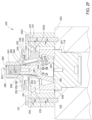
- Figures 2E and 2F illustrate the locking assembly 240 in an unlocked position when first attaching the locking assembly 240 to the fluid end body 105 or when wanting to remove and repair/replace the valve cover 116 or otherwise requiring access to the internal components of the fluid end 100.
- the second actuator 242 When the locking assembly 240 is in the unlocked position, the second actuator 242 is in a lower position and the plurality of wedges 243 are in an unlocked position. In the unlocked position, the external locking surfaces 2002 are disengaged from and disposed at a gap from the internal locking surfaces 2001 of adjacent internal grooves 254 formed in the lock ring 247.
- the first actuator 241, the second actuator 242, and the wedges 243 may be inserted into the lock ring 247 or removed from the lock ring 247 as an assembly.
- the first actuator 241 is then rotated (such as by a wrench used to grip and rotate an upper portion 264 of the first actuator 241) in a first rotational direction RD1 about the center axis 286 and relative to the second actuator 242 and the plurality of wedges 243 such that the second actuator 242 is driven upward in the longitudinal direction D1 and away from the valve cover 116 via a threaded interface 258 formed between the upper portion 264 of the first actuator 241 and an upper portion 268 of the second actuator 242.
- the upper portion 268 of the second actuator 242 may be a threaded shaft including the one or more coupling surfaces 285 that engage the one or more coupling surfaces 284 of the first actuator 241.
- the threaded outer surface of the second actuator 242 engages the threaded inner surface of the first actuator 241 to form the threaded interface 258 that moves the second actuator 242 upward or downward depending on the direction of rotation of the first actuator 241.
- first actuator 241 As the upper inner surface 290 of the first actuator 241 is engaged with the shoulder portions 249 of the wedges 243, turning the first actuator 241 to rotate the first actuator 241 moves (such as by threading) the one or more coupling surfaces 285 of the second actuator 242 upward and into the one or more coupling surfaces 284 of the first actuator 241.
- the threading of the second actuator 242 into the first actuator 241 moves the second actuator 242 upward in the longitudinal direction D1 from the lower position to an upper position (illustrated in Figure 2C ).
- the second actuator 242 moves upward in the longitudinal direction D1 relative to the valve cover 116, the fluid end body 105, the lock ring 247, the load ring 246, the wedges 243, and the first actuator 241.
- the tapered interfacing surface 261 of the second actuator 242 engages the tapered interfacing surfaces 262 of the wedges 243 and forces the wedges 243 radially outward in the direction D2 and into engagement with the lock ring 247.
- the tapered interfacing surface 261 slides upward along the tapered interfacing surfaces 262 of the wedges 243 and applies outward forces to the wedges 243 to push the wedges 243 outward.
- the guide slots 251 and the guide blocks 244 are substantially parallel with the tapered surfaces 261, 262 of the second actuator 242 and the wedges 243.
- each wedge 243 moves outward in directions D2 from the unlocked position to a locked position (illustrated in Figure 2C ).
- the wedges 243 move outward from the second actuator 242 to the lock ring 247.
- the lower surface 231 of each wedge 243 slides along the upper surface 239 of the load ring 246 and outward.
- each set of external locking surfaces 2002 moves toward one of the internal grooves 254.
- the external locking surfaces 2002 engaged with the internal locking surfaces 2001, the wedges 243 engaged with the load ring 246, and the load ring 246 engaged with the valve cover 116 facilitate retaining the valve cover 116 in the opening 201 and into sealing engagement with the fluid end body 105 during operation of the fluid end 100.
- the external locking surfaces 2002 engaged against the internal locking surfaces 2001 facilitates retaining the wedges 243 in a substantially fixed position relative to the fluid end body 105
- the engagements between the wedges 243, the load ring 246, and the valve cover 116 facilitate retaining the valve cover 116 in a substantially fixed position relative to the fluid end body 105.
- the wedges 243 may apply retaining surfaces directly or indirectly to the valve cover 116.
- FIG. 2D is a schematic cross-sectional view of the locking assembly 240 illustrated in Figure 2C along lines 2D - 2D, with the locking assembly 240 in the locked position, according to one implementation.
- the lock ring 247 includes ten openings 266 disposed circumferentially about the lock ring 247, and ten bolts 107 disposed in the openings 266.
- the lock ring 247 may also include an opening that is used with a handle, such as a T-shaped handle, to lift, lower, and move the locking assembly 240.
- the lock ring 247 may omit the openings 266, such as in an embodiment where the lock ring 247 is welded to the fluid end body 105 or an embodiment where the lock ring 247 is integrally formed with the fluid end body 105.
- the locking assembly 240 includes five wedges 243 disposed circumferentially about the second actuator 242.
- the body portion 280 includes one tapered interfacing surface 261.
- the guide blocks 244 (five are shown) are coupled to the body portion 280 of the second actuator 242 circumferentially about the body portion 280.
- Each wedge 243 includes a guide slot 251 (five are shown) formed in the tapered interfacing surface 262 of the respective wedge 243.
- Each guide block 244 is disposed within a respective guide slot 251.
- the fasteners 245 are disposed through the body portion 280 and at least partially through a respective one of the guide blocks 244 to couple the guide blocks 244 to the second actuator 242.
- the fasteners 245 may be disposed such that head portions of the fasteners 245 are disposed within the second actuator 242 (as shown in Figures 2C and 2D ).
- the fasteners 245 may be disposed such that head portions of the fasteners 245 are disposed outside of the second actuator 242 and within or outside of the guide blocks 244.
- the fasteners 245 may be disposed completely through the body portion 280 (as shown in Figure 2C ) or partially through the body portion 280 in openings that extend partially through the body portion 280.
- each guide block 244 of the second actuator 242 applies an outward force to each wedge 243 to push the wedge 243 outward to the locked position.
- Each guide block 244 moves upward in the respective guide slot 251 as the second actuator 242 moves upward from the lower position to the upper position.
- the guide blocks 244 apply an inward force to each wedge 243 to pull each wedge 243 inward to the unlocked position.
- Each guide block 244 moves downward in the respective guide slot 251 as the second actuator 242 moves downward from the upper position to the lower position.
- the tapering inward and upward in the longitudinal direction D1 of the one or more tapered interfacing surfaces 261 and the tapered interfacing surfaces 262 facilitates design simplicity and locking simplicity, effective and stable locking and unlocking of the locking assembly 240, weight savings, quick and easy installation and removal of the locking assembly 240, smaller overall size of the locking assembly 240, cost savings, and enhanced operational lifespans for the locking assembly 240.
- the movement of the second actuator 242 upward to the upper position to push the wedges 243 outward to the locked position also facilitates design simplicity and locking simplicity, effective and stable locking and unlocking of the locking assembly 240, weight savings, quick and easy installation and removal of the locking assembly 240, smaller overall size of the locking assembly 240, cost savings, and enhanced operational lifespans for the locking assembly 240.
- the locking assembly 240 may be moved from the locked position (illustrated in Figure 2C ) back to the unlocked position (illustrated in Figure 2F ), for example, to remove the valve cover 116 from the fluid end body 105 and/or to perform maintenance on the fluid end 100.
- the locking assembly 240 may be moved back to the unlocked position such that the first actuator 241, the second actuator 242, and the wedges 243 may be removed as an assembly from a central opening 296 (illustrated in Figure 2L ) of the lock ring 247.
- the locking assembly 240 is moved back to the unlocked position by turning the first actuator 241 in a second rotational direction RD2 that is opposite of the first rotational direction RD1 to drive the second actuator 242 downward in a longitudinal direction D3 toward the valve cover 116 using the threaded interface 258.
- first actuator 241 in the second rotational direction RD2 moves (such as by threading) the one or more coupling surfaces 285 of the second actuator 242 out of the one or more coupling surfaces 284 of the first actuator 241. Threading the second actuator 242 out of the first actuator 241 moves the second actuator 242 downward in the longitudinal direction D3 that is opposite of the upward longitudinal direction D1. The second actuator 242 moves downward from the upper position back to the lower position. As the second actuator 242 moves downward, the tapered interfacing surface 261 slides downward along the tapered interfacing surfaces 262 of the wedges 243.
- the guide blocks 244 coupled to the body portion 280 of the second actuator 242 apply an inward force to each wedge 243 to pull the wedges 243 inward in inward directions D4 toward the center axis 286 and from the lock ring 247.
- the guide blocks 244 pull on the wedges 243 using the engagement between the guide blocks 244 and the guide slots 251 of the wedges 243.
- the lower surfaces 231 slide inward in the inward directions D4 toward the center axis 286.
- the wedges 243 are retracted and moved radially inward in the inward directions D4 and out of engagement from the lock ring 247.
- the entire locking assembly 240 can then be removed to provide access to the valve cover 116 and/or internal components of the fluid end 100.
- each wedge 243 In the unlocked position (illustrated in Figure 2F ), the outer surface 292 of the shoulder portion 249 of each wedge 243 is disposed at a second gap from the recessed inner surface 293. The second gap is larger than the first gap (illustrated in Figure 2C ).
- Figure 2G is a schematic isometric partial view of the first actuator 241 of the locking assembly 240, according to one implementation.
- the first actuator 241 includes a center axis extending through a center of the first actuator 241 and through the central opening 269.
- the center axis is longitudinally aligned with the center axis 286 of the second actuator 242 in the locking assembly 240, as illustrated in Figures 2C and 2F .
- the upper surface 288 and the lower surface 289 of the first actuator 241 extend perpendicularly to the center axis of the first actuator 241.
- FIG. 2H is a schematic isometric partial view of the second actuator 242 of the locking assembly 240, according to one implementation.
- Each guide block 244 coupled to the body portion 280 of the second actuator 242 may be partially disposed in or on a plurality of guide block mounting surfaces 299 formed in the one or more tapered interfacing surface 261.
- the guide block mounting surfaces 299 are recessed, flat, or another shape.
- the body portion 280 is a base portion of the second actuator 242.
- at least a portion of the rectangular portion of each guide block 244 is at least partially disposed in or on one of the guide block mounting surfaces 299.
- the one or more tapered interfacing surfaces 261 taper inward and upward toward the center axis 286 in the longitudinal direction D1.
- the one or more tapered interfacing surfaces 261 are neither parallel nor perpendicular to the center axis 286.
- Figure 2J is a schematic isometric partial view of one of the wedges 243 of the locking assembly 240, according to one implementation.
- Figure 2M is a schematic isometric partial view of the valve cover 116 of the fluid end 100, according to one implementation.
- the valve cover 116 includes a center axis extending through a center of the valve cover 116.
- the center axis of the valve cover 116 is longitudinally aligned with the center axis 286 of the second actuator 242 of the locking assembly 240, as illustrated in Figures 2C and 2F .
- Figure 3 is a schematic isometric partial view of a fluid end 100 having a fluid end body 105 and a locking assembly 440 in an unlocked position, according to one implementation.
- Figure 4A is a schematic cross-sectional view of the fluid end 100 illustrated in Figure 3 along lines 4A - 4A, according to one implementation.
- the fluid end 100 includes a plurality of bores 110A-110D (110A and 110D are shown Figure 4A ) formed in the fluid end body 105.
- the fluid end 100 is adapted to couple to a power end 112 via a pony rod 114. While only one pony rod 114 is shown, the power end 112 may have a pony rod that couples to each of the bores 110A of the fluid end 100.
- each of the suction covers 215 may be replaced with a cover similar to the valve covers 316, and/or the retainer nuts 115 may be replaced with a locking assembly similar to the locking assembly 440.
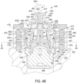
- Figure 4B is a schematic enlarged cross-sectional partial view of the fluid end 100 and the locking assembly 440 illustrated in Figure 4A , according to one implementation.
- the locking assembly 440 is illustrated in the unlocked position in Figure 4B .
- the locking assembly 440 includes a second actuator 441.
- the second actuator 441 includes a body 442 and a shaft 443 that protrudes upwardly from the body 442 in a longitudinal direction D1.
- the body 442 is a base of the second actuator 441.
- the body 442 includes one or more tapered interfacing surfaces 444 and a recessed surface 445 formed in a lower surface 446 of the body 442.
- the second actuator 441 also includes a center axis 447 extending through the body 442 and the shaft 443.
- the locking assembly 440 includes a plurality of wedges 448 disposed about the second actuator 441.
- Each wedge 448 includes a tapered interfacing surface 449, an outer surface 450, and a set of one or more external locking surfaces 4002 formed in the outer surface 450.
- the external locking surfaces 4002 are angled. In one embodiment, which can be combined with other embodiments, each set of one or more external locking surfaces 4002 is part of a set of external teeth 451.
- the tapered interfacing surface 449 of each wedge 448 is engaged with one of the tapered interfacing surfaces 444 of the second actuator 441 such that the tapered interfacing surfaces 444 slide upward and downward along the tapered interfacing surfaces 449 of the wedges 448.
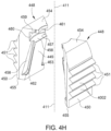
- the first guide slot 456 and the second guide slot 457 of each wedge 448 extend from the first shoulder 458 and end short of the lower surface 455 to form a third shoulder 462 (shown in Figure 4H ) and a fourth shoulder 463 (shown in ghost in Figure 4B ), respectively.
- the present disclosure contemplates that the formation of the guide blocks 453 and the first and second guide slots 456, 457 may be reversed such that the guide blocks 453 are disposed on the wedges 448 and the first and second guide slots 456, 457 are formed on the second actuator 441.
- the guide blocks 453 of the implementation shown hereafter will be referred to as "the protrusions 453.”
- the locking assembly 440 includes a first actuator 464 disposed at least partially above the second actuator 441 and at least partially about the shaft 443 of the second actuator 441.
- the first actuator 464 includes a central opening 465 and one or more coupling surfaces 466.
- the one or more coupling surfaces 466 include a threaded inner surface interface with and thread with the threaded outer surface of the shaft 443 of the second actuator 441.
- the one or more coupling surfaces 466 interface with and are disposed in coupling engagement with the one or more coupling surfaces 452 of the second actuator 441.
- the first actuator 464 includes an upper surface 467 and a lower surface 468.
- the central opening 465 extends between the upper surface 467 and the lower surface 468.
- the first actuator 464 includes a tool interface 469, such as a hex tool interface, for turning the first actuator 464.
- the lower surface 468 of the first actuator 464 is engaged with the first shoulder 458 of each wedge 448 of the plurality of wedges 448.
- the first actuator 464 includes a first portion 470 and a second portion 472 disposed below the first portion 470.
- the second portion 472 is wider than the first portion 470.
- the second portion 472 includes an outer surface 473 and an upper surface 474 between the lower surface 468 and the upper surface 467 of the first portion 470.
- the outer surface 473 of the second portion 472 may be engaged with the recessed surface 460 of each wedge 448 and the upper surface 474 of the second portion 472 may be engaged with the second shoulder 459 of each wedge 448.
- the first actuator 464 is a nut and the second shoulder 459 of each wedge 448 is omitted.
- the second actuator 441 is disposed at least partially below the first actuator 464 in the implementations shown in Figures 4B and 4C . In one embodiment, which can be combined with other embodiments, the second actuator 441 is disposed at least partially above the first actuator 464. In one embodiment, which can be combined with other embodiments, the second actuator 441 is not disposed above or below the first actuator 464 but is disposed about or within the first actuator 464.
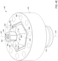
- the locking assembly 440 includes a lock ring 475 disposed about the plurality of wedges 448.
- the lock ring 475 is a flange.
- the lock ring 475 includes an outer surface 476 and a plurality of inner surfaces 477, an upper surface 478, and a lower surface 479.
- the lock ring 475 includes a plurality of fastener openings 480 extending from the upper surface 478 to the lower surface 479 of the lock ring 475.
- a bolt 403 of a plurality of bolts 403 is disposed through each fastener opening 480 to fasten the lock ring 475 to the fluid end body 105 and mount the lock ring 475 to an exterior surface 202 of the fluid end body 105.
- the lock ring 475 may be disposed adjacent the opening 201 such that the sets of internal locking surfaces 4001 and the sets of internal grooves 482 are disposed along the opening 201 of the fluid end body 105.
- the lock ring 475 may also include an opening that is used with a handle, such as a T-shaped handle, to lift, lower, and move the locking assembly 475.
- the lock ring 475 may omit the fastener openings 480, such as in an embodiment where the lock ring 475 is welded to the fluid end body 105 or an embodiment where the lock ring 475 is integrally formed with the fluid end body 105.
- Figure 4B illustrates the locking assembly 440 in the unlocked position.
- the second actuator 441 is in a lower position and the wedges 448 are in an unlocked position.
- the external locking surfaces 4002 of the wedges 448 are disengaged from and disposed at a gap from the internal locking surfaces 4001 of adjacent sets of internal grooves 482 formed in the lock ring 475.
- the lock ring 475 is mounted to the fluid end body 105 using the bolts 403 that mount the lock ring 475 to the exterior surface 202.
- the lower surface 455 of each wedge 448 is disposed in engagement with the upper surface 484 of the valve cover 316.
- the second actuator 441, the first actuator 464, and the wedges 448 may be inserted into the lock ring 475 or removed from the lock ring 475 as an assembly.
- Figure 4C is a schematic enlarged cross-sectional partial view of the fluid end 100 and the locking assembly 440 illustrated in Figure 4B , with the locking assembly 440 in a locked position, according to one implementation.
- the locking assembly 440 is in the locked position
- the second actuator 441 is in the upper position and the wedges 448 are in the locked position, as illustrated in Figure 4C .
- the outer surface 473 of the first actuator 464 is disposed at a gap from the recessed surface 460 of each wedge 448.
- the teeth of the sets of external teeth 451 of the wedges 448 are engaged with and received in the recesses of the sets of internal grooves 482.
- the aspects also facilitate preventing the valve cover 316 from backing out of the opening 201 during high pressure operations of the fluid end 100.
- the second actuator 441, the first actuator 464, and the wedges 448 are retained within the lock ring 475.
- the locking assembly 440 including the wedges 448 are mounted to the fluid end body 105 in the locked position using at least the lock ring 475 mounted to the fluid end body 105.
- the aspects of the locking assembly 440 facilitate preventing backing out of the valve covers 316 and maintaining sealed connections of the fluid end 100 during high pressure operations of the fluid end 100.
- the locking assembly 440 may be moved from the locked position (illustrated in Figure 4C ) back to the unlocked position (illustrated in Figure 4B ), for example, to remove the valve cover 316 from the fluid end body 105 and/or to perform maintenance on the fluid end 100.
- the locking assembly 440 may be moved back to the unlocked position such that the second actuator 441, the first actuator 464, and the wedges 448 may be removed as an assembly from the central opening 496 (illustrated in Figure 4G ) of the lock ring 475.
- the locking assembly 440 is moved back to the unlocked position by turning the first actuator 464 in a second rotational direction RD2 that is opposite of the first rotational direction RD1.
- first actuator 464 in the second rotational direction RD2 moves (such as by threading) the one or more coupling surfaces 452 of the second actuator 441 out of the one or more coupling surfaces 466 of the first actuator 464. Threading the second actuator 441 out of the first actuator 464 moves the second actuator 441 downward in a downward longitudinal direction D2 that is opposite of the longitudinal direction D1. The second actuator 441 moves downward from the upper position back to the lower position. As the second actuator 441 moves downward, the tapered interfacing surfaces 444 slide downward along the tapered interfacing surfaces 449 of the wedges 448.
- each protrusion 453 of the second actuator 441 applies an outward force to the first guide slot 456 and the second guide slot 457 of each wedge 448 to push the wedge 448 outward to the locked position.
- Each protrusion 453 moves upward in the respective first guide slot 456 and second guide slot 457 as the second actuator 441 moves upward from the lower position to the upper position.
- Figure 4E is a schematic isometric partial view of the locking assembly 440 and the valve cover 316 illustrated in Figures 3 and 4A , with the locking assembly 440 in the unlocked position, according to one implementation.
- Each set of internal teeth 481 (six are included in the lock ring 475) is formed in one of the inner surfaces 477 between the internal grooves of a set of internal grooves 482.
- Each set of internal locking surfaces 4001 (six are included in the locking ring 475) formed in one of the inner surfaces 477.
- the lock ring 475 includes a center axis 498 extending through the central opening 496 and through a center of the ring.
- the center axis 498 of the lock ring 475 is longitudinally aligned with the center axis 447 of the second actuator 441 in the locking assembly 440, as illustrated in Figures 4B and 4C .
- Figure 4I is a schematic isometric partial view of the first actuator 464 of the locking assembly 440, according to one implementation.
- the first actuator 464 includes a center axis 412 extending through a center of the first actuator 464 and through the central opening 465.
- the center axis 412 is longitudinally aligned with the center axis 447 of the second actuator 441 in the locking assembly 440, as illustrated in Figures 4B and 4C .
- the upper surface 474 and the lower surface 468 of the second portion 472 extend perpendicularly to the center axis 412.
- the surfaces and slots described herein such as the one or more tapered interfacing surfaces 444 and the tapered interfacing surfaces 449, may be planar in profile or arcuate in profile.
- the second actuator 542 includes a body 581 that is pentagonal in shape, including rounded or chamfered edges between the five sides of the pentagonal shape.
- the first actuator 541 includes a stud 590 that is rotatable.
- the stud 590 includes a hex portion 591 for interfacing with a tool, such as a wrench, and a threaded portion 592.
- the body 581 includes one or more tapered interfacing surfaces 561.
- the tapered interfacing surfaces 561 taper inwardly toward a center axis of the body 581 and downward in the longitudinal direction D3 that points toward the fluid end body 105.
- the present disclosure contemplates that use of "downward” or “downwardly” herein may be parallel to gravitational forces, or, depending on orientations of the locking assemblies, may be disposed at an oblique angle relative to the gravitational forces or disposed perpendicularly to gravitational forces.
- the one or more tapered interfacing surfaces 561 (five are included as part of the pentagonal shape) interface with and engage a set of one or more tapered interfacing surfaces 562 of each of the wedges 543 (five wedges 543 are included) such that the one or more tapered interfacing surfaces 561 slide upward and downward along the one or more tapered interfacing surfaces 562 of the wedges 543.
- the one or more tapered interfacing surfaces 562 of each wedge 543 taper inward relative to the center axis of the body 581 and downward in the longitudinal direction D3.
- the one or more tapered interfacing surfaces 561 include one or more tapered outer surfaces and the one or more tapered interfacing surfaces 562 include one or more tapered inner surfaces.
- the guide blocks 544 (five guide blocks 544 are included) are coupled to the second actuator 542 (as shown in Figure 5A ) by a plurality of fasteners 545, such as screws.
- the fasteners 545 extend through the respective guide block 544 and partially through the body 581 of the second actuator 542.
- the guide blocks 544 may be integrally formed with the second actuator 542.
- the guide blocks 544 are integrally formed with the second actuator 542 such that each guide block 544 is a protrusion that protrudes from the tapered interfacing surface 561.
- Each wedge 543 includes an upper surface 530, a lower surface 531, and a guide slot 551 formed in the tapered interfacing surface 562 of the respective wedge 543.
- the tapered interfacing surface 562 of each wedge 543 extends from the lower surface 531 each respective wedge 543 to the upper surface 530.
- the guide blocks 544 are located at least partially within the guide slots 551 formed within each wedge 543 to rotationally couple the second actuator 542 to the plurality of wedges 543 but allow axial relative movement between the second actuator 542 and the plurality of wedges 543.
- the guide blocks 544 and the guide slots 551 form a guide mechanism configured to keep the wedges 543 coupled to the second actuator 542.
- the guide mechanism can be a dovetail, circular, or other shaped interface. In one embodiment, which can be combined with other embodiments, the guide mechanism can be reversed such that the guide slots 551 are formed on the second actuator 542 and the guide blocks 544 are coupled to or integrally formed with the wedges 543.
- the plurality of wedges 543 have a set of one or more external locking surfaces 5002 that engage with one or more internal locking surfaces 5001 of a lock ring 547 and one or more internal grooves 554 (two are shown) formed on an inner surface 577 of the lock ring 547.
- the locking surfaces 5002 are part of one or more external teeth formed on the wedges 543.
- the locking surfaces 5002 are angled.
- the plurality of wedges 543 are positioned on top of an upper surface 539 of a plate 546, which is positioned on top of a valve cover 516.
- the plate 546 is a ring, such as a load ring.
- the plate 546 may be integrally formed with the valve cover 516 (or integrally formed with any other component, such as a plug, that is secured within the fluid end body 105).
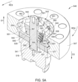
- Figures 5A and 5B illustrate the locking assembly 540 in the locked position, which secures the valve cover 516 within the fluid end body 105 during operation.
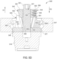
- Figures 5C and 5D illustrate the locking assembly 540 in an unlocked position when first attaching the locking assembly 540 to the fluid end body 105 or when wanting to remove and repair/replace the valve cover 516 or otherwise requiring access to the internal components of the fluid end 100.
- the second actuator 542 When the locking assembly 540 is in the unlocked position, the second actuator 542 is in an upper position, the first actuator 541 is in an upper positions, and the plurality of wedges 543 are in an unlocked position.
- the external locking surfaces 5002 are disengaged from and disposed at a gap from the internal locking surfaces 5001 of adjacent internal grooves 554 formed in the lock ring 547.
- the first actuator 541, the second actuator 542, and the wedges 543 may be inserted into the lock ring 547 or removed from the lock ring 547 as an assembly.
- the locking assembly 540 is attached to the fluid end body 105 by bolting the lock ring 547 to the fluid end body 105 such that the plate 546 is positioned on top of the valve cover 516.
- the lock ring 547 may be integrally formed with the fluid end body 105 such that no bolting is required.
- the locking assembly 540 is in the unlocked position as shown in Figures 5C and 5D .
- the first actuator 541 is then rotated (such as by a wrench used to grip and rotate the hex portion 591 of the first actuator 541) in a first rotational direction RD3 and relative to the second actuator 542 and the plurality of wedges 543 such that the second actuator 542 and the first actuator 541 is driven downward in the longitudinal direction D3 and toward the valve cover 516 via a threaded interface formed between the first actuator 541 and the second actuator 542.
- the threaded inner surface of the first actuator 541 engages the threaded outer surface of the second actuator 542 to form the threaded interface that moves the second actuator 242 upward or downward depending on the direction of rotation of the first actuator 541.
- the first actuator 541 functions as a turnbuckle.
- threaded portion 592 includes a left-hand thread and the second threaded portion 599 includes a righthand thread.
- the wedges 543 When the wedges 543 are moved radially outward into contact with the lock ring 547, the wedges 543 move slightly downward toward the fluid end body 105 to apply a force to the plate 546 and the valve cover 516 due to the tapered external locking surfaces 5002 engaging and moving along the tapered internal locking surfaces 5001 of the internal grooves 554.
- the wedges 543 may move slightly downward relative to the lock ring 547 since the lock ring 547 is bolted to (or integrally formed with) the fluid end body 105.
- the internal teeth of the lock ring 547 are engaged with and at least partially between the external teeth of the wedges 543.
- the internal teeth of the lock ring 547 are interleaved between the external teeth of the wedges 543.
- external locking surfaces of the external locking surfaces 5002 of the wedges 543 are engaged with internal locking surfaces of the internal locking surfaces 5001 of the lock ring 547.
- Figure 5C is a schematic enlarged cross-sectional isometric view of the locking assembly 540 in the unlocked position, according to one implementation.
- Figure 5D is a schematic enlarged cross-sectional side view of the locking assembly 540 in the unlocked position, according to one implementation.
- the present disclosure contemplates that one or more of the aspects, features, components, and/or properties of the locking assembly 240 may be combined with one or more of the aspects, features, components, and/or properties of the locking assembly 440 and/or the locking assembly 540.
Landscapes
- Engineering & Computer Science (AREA)
- General Engineering & Computer Science (AREA)
- Mechanical Engineering (AREA)
- Valve Housings (AREA)
Description
- The disclosure relates to locking assembly apparatus for fluid ends, and associated components thereof. In one aspect, the present disclosure relates to locking assembly apparatus for a cover disposed in an opening of a fluid end.
- Covers may be used on fluid ends in the oil and gas industry, for example on fluid ends of frac pumps or mud pumps. Covers can back out of fluid ends, for example from high pressure operation of the fluid ends. Attempts to lock these covers carry extra parts, reduced efficiencies, increased operational times, complex design and operation, and increased costs.
US-2017/089334 A1 discloses a locking assembly for a pump or fluid end. The described locking assembly is adapted to couple to a fluid end proximal to a valve cover opening, and includes an insert comprising a plurality of segments, and a cone adapted to be at least partially disposed within an opening in the insert. - Therefore, there is a need for a locking assembly that facilitates high operating pressure capabilities, sealing during operation, higher efficiencies, less parts, reduced operational times, less complex operation and design, and reduced costs.
- Implementations of the present disclosure relate to a locking assembly apparatus for fluid ends, and associated components thereof.
- In one implementation, a locking assembly for fluid ends includes a first actuator, the first actuator including one or more coupling surfaces. The locking assembly also includes a second actuator disposed at least partially below the first actuator. The second actuator includes a body, the body including one or more tapered interfacing surfaces. The second actuator also includes one or more coupling surfaces disposed in coupling engagement with the one or more coupling surfaces of the first actuator, and a center axis extending in a longitudinal direction through the body, where the one or more tapered interfacing surfaces taper inward at an angle relative to the center axis. The locking assembly also includes a plurality of wedges disposed about the second actuator and movable between an unlocked position and a locked position. Each wedge of the plurality of wedges includes a set of one or more external locking surfaces, and a set of one or more tapered interfacing surfaces, where the one or more tapered interfacing surfaces of each wedge is configured to engage with one of the one or more tapered interfacing surfaces of the second actuator. The locking assembly also includes a lock ring disposed about the plurality of wedges. The lock ring includes a set of one or more internal locking surfaces configured to engage with the external locking surfaces of each wedge of the plurality of wedges. The body of the second actuator comprises a plurality of guide blocks; and each wedge of the plurality of wedges comprises a guide slot formed in a respective tapered interfacing surface of the set of one or more tapered interfacing surfaces of the respective wedge, and each guide slot includes a guide block of the plurality of guide blocks disposed at least partially in the respective guide slot.
- So that the manner in which the above-recited features of the disclosure can be understood in detail, a more particular description of the disclosure, briefly summarized above, may be had by reference to embodiments, some of which are illustrated in the appended drawings. It is to be noted, however, that the appended drawings illustrate only typical embodiments of this disclosure and are therefore not to be considered as limiting the scope of the invention, which is solely defined by the appended claims.
-
Figure 1 is a schematic isometric partial view of a fluid end having a fluid end body and a locking assembly in a locked position, according to one implementation. -
Figure 2A is a schematic cross-sectional view of the fluid end illustrated inFigure 1 alonglines 2A-2A, according to one implementation. -
Figure 2B is a schematic enlarged cross-sectional isometric view of the locking assembly in a locked position, according to one implementation. -
Figure 2C is a schematic enlarged cross-sectional side view of the locking assembly in the locked position, according to one implementation. -
Figure 2D is a schematic cross-sectional view of the locking assembly illustrated inFigure 2C along lines 2D - 2D, with the locking assembly in the locked position, according to one implementation. -
Figure 2E is a schematic enlarged cross-sectional isometric view of the locking assembly in an unlocked position, according to one implementation. -
Figure 2F is a schematic enlarged cross-sectional side view of the locking assembly in the unlocked position, according to one implementation. -
Figure 2G is a schematic isometric partial view of a first actuator of the locking assembly, according to one implementation. -
Figure 2H is a schematic isometric partial view of a second actuator of the locking assembly, according to one implementation. -
Figure 2I is a schematic isometric partial view of wedges of the locking assembly, according to one implementation. -
Figure 2J is a schematic isometric partial view of one of the wedges of the locking assembly, according to one implementation. -
Figure 2K is a schematic isometric view of a load ring of the locking assembly, according to one implementation. -
Figure 2L is a schematic isometric partial view of a lock ring of the locking assembly, according to one implementation. -
Figure 2M is a schematic isometric partial view of a valve cover of the fluid end, according to one implementation. -
Figure 3 is a schematic isometric partial view of a fluid end having a fluid end body and a locking assembly in an unlocked position, according to one implementation. -
Figure 4A is a schematic cross-sectional view of the fluid end illustrated inFigure 3 alonglines 4A - 4A, according to one implementation. -
Figure 4B is a schematic enlarged cross-sectional partial view of the fluid end and the locking assembly illustrated inFigure 4A , according to one implementation. -
Figure 4C is a schematic enlarged cross-sectional partial view of the fluid end and the locking assembly illustrated inFigure 4B , with the locking assembly in a locked position, according to one implementation. -
Figure 4D is a schematic cross-sectional view of the locking assembly illustrated inFigure 4A alonglines 4D - 4D, with the locking assembly in the unlocked position, according to one implementation. -
Figure 4E is a schematic isometric partial view of the locking assembly and the valve cover illustrated inFigures 3 and4A , with the locking assembly in the unlocked position, according to one implementation. -
Figure 4F is a schematic isometric partial view of the second actuator of the locking assembly, according to one implementation. -
Figure 4G is a schematic isometric partial view of the lock ring of the locking assembly, according to one implementation. -
Figure 4H is a schematic isometric partial view of two of the wedges of the locking assembly, according to one implementation. -
Figure 4I is a schematic isometric partial view of the first actuator of the locking assembly, according to one implementation. -
Figure 4J is a schematic isometric partial view of the valve cover of the fluid end, according to one implementation. -
Figure 5A is a schematic enlarged cross-sectional isometric view of a locking assembly in a locked position, according to one implementation. -
Figure 5B is a schematic enlarged cross-sectional side view of the locking assembly in the locked position, according to one implementation. -
Figure 5C is a schematic enlarged cross-sectional isometric view of the locking assembly in the unlocked position, according to one implementation. -
Figure 5D is a schematic enlarged cross-sectional side view of the locking assembly in the unlocked position, according to one implementation. - To facilitate understanding, identical reference numerals have been used, where possible, to designate identical elements that are common to the figures. It is contemplated that elements disclosed in one implementation may be beneficially utilized on other implementations without specific recitation.
- Aspects of the disclosure relate to locking assembly apparatus and methods for fluid ends, and associated components thereof. In one aspect, the present disclosure relates to locking assembly apparatus and methods for a valve cover disposed in an opening of a fluid end.
-
Figure 1 is a schematic isometric partial view of afluid end 100 having afluid end body 105 and alocking assembly 240 in a locked position, according to one implementation. Thefluid end 100 includes a plurality ofbores 110A-110D (bores 110A,bores 110B, andbores 110D are shown inFigure 2A ) formed in the side of thefluid end body 105. Thefluid end 100 illustrated includes a plurality ofretainer nuts 115 disposed in each of thebores 110C. Thefluid end 100 is adapted to couple to apower end 112 via apony rod 114. While only onepony rod 114 is shown, thepower end 112 may have a pony rod that couples to each of thebores 110A (shown inFigure 2A ) of thefluid end 100. Aplunger clamp 172 or any other rod connector mechanism may be disposed between thefluid end 100 and thepony rod 114. Adischarge flange 171 may be coupled to opposing ends of thefluid end body 105 for connecting hoses with a discharge manifold. A lockingassembly 240 is disposed above one of the valve covers 116. The present disclosure contemplates that a lockingassembly 240 may be disposed above each one of the valve covers 116 (five are illustrated). Although the lockingassembly 240 is described herein as being used with a frac pump, the lockingassembly 240 can be used with any other types of pumps, including but not limited to mud pumps, positive displacement pumps, etc. - The
fluid end 100 includes a plurality of valve covers 116. Eachvalve cover 116 is disposed at least partially in anopening 201 formed in the top of thefluid end body 105. Theopenings 201 are at least part of thebores 110B. Four valve covers 116 are shown exposed along the top of thefluid end body 105. Thecenter valve cover 116 is secured to thefluid end body 105 by the lockingassembly 240. Although the lockingassembly 240 is described herein as securing valve covers 116, the lockingassembly 240 may be used to secure a plug, a suction cover, a discharge cover, an access cover, a strainer cover, a retainer nut, and/or any other type of component (such as the cylindrical shapedvalve cover 116 as shown inFigure 2M ) that needs to be secured to thefluid end body 105. Thefluid end 100 illustrated includes aretainer nut 115 disposed in each of thebores 110B and avalve cover 116 disposed in eachopening 201. -
Figure 2A is a schematic cross-sectional view of thefluid end 100 illustrated inFigure 1 alonglines 2A-2A, according to one implementation.Bores Figure 2A . Aplunger 200 is shown disposed in thebore 110A, and avalve assembly 205 having aspring 210 is shown disposed in thebore 110B. Asuction cover 215 is shown disposed in thebore 110C, and asuction valve assembly 271 is shown in thebore 110D. Thesuction cover 215 is disposed inwards of theretainer nut 115 relative to thefluid end body 105. Thevalve cover 116 is a discharge cover. Avalve body 222 as well as avalve seat 224 may also be disposed in thebores fluid end body 105 may also include adischarge manifold 220 formed therein that is in selective communication with at least thebore 110B. Thebores 110A-110D formed in thefluid end body 105 intersect within thefluid end body 105 at ajunction 225. The present disclosure contemplates that each of the suction covers 215 may be replaced with a cover similar to the valve covers 116, and/or theretainer nuts 115 may be replaced with a locking assembly similar to the lockingassembly 240. - As shown in
Figure 2A , the lockingassembly 240 is coupled to thefluid end body 105 by a plurality ofbolts 107 that are disposed through a plurality ofopenings 266 formed in alock ring 247 and threaded into thefluid end body 105. Abolt 107 is disposed through each opening 266 to fasten thelock ring 247 to thefluid end body 105 and mount thelock ring 247 to anexterior surface 202 of thefluid end body 105. Thelock ring 247 is disposed about the plurality ofwedges 243. In one example, thelock ring 247 is a flange. Thelock ring 247 includes anouter surface 276 and aninner surface 277. -
Figure 2B is a schematic enlarged cross-sectional isometric view of the lockingassembly 240 in a locked position, according to one implementation.Figure 2C is a schematic enlarged cross-sectional side view of the lockingassembly 240 in the locked position, according to one implementation. Referring toFigures 2B and2C , the lockingassembly 240 includes afirst actuator 241, asecond actuator 242 at least partially disposed within acentral opening 269 of thefirst actuator 241, and a plurality ofwedges 243 that are each coupled to thefirst actuator 241. Thesecond actuator 242 is disposed at least partially below thefirst actuator 241 in the implementations shown inFigures 2B and2C . In one embodiment, which can be combined with other embodiments, thesecond actuator 242 is disposed at least partially above thefirst actuator 241. In one embodiment, which can be combined with other embodiments, thesecond actuator 242 is not disposed above or below thefirst actuator 241 but is disposed about or within thefirst actuator 241. - The
lock ring 247 includes one or more internal locking surfaces 2001. In one embodiment, which can be combined with other embodiments, the lockingsurfaces 2001 are part of one or moreinternal teeth 232 formed in theinner surface 277. Theinternal locking surfaces 2001 are angled. Theinternal teeth 232 are formed between a plurality ofinternal grooves 254 formed in theinner surface 277 of thelock ring 247. The present disclosure contemplates that thelock ring 247 may be a separate component from thefluid end body 105, or that thelock ring 247 may be integrally formed with thefluid end body 105 or any of the other fluid containing bodies. The present disclosure contemplates that thelock ring 247 may be disposed adjacent theopening 201 such that the sets ofinternal teeth 232 and theinternal grooves 254 are disposed along theopening 201 of thefluid end body 105. - The
first actuator 241 is disposed at least partially above thesecond actuator 242. In one example, thefirst actuator 241 is disposed at least partially about ashaft portion 281 of thesecond actuator 242. Thefirst actuator 241 includes thecentral opening 269 and one or more coupling surfaces 284. The one or more coupling surfaces 284 includes a threaded inner surface. Thesecond actuator 242 includes one or more coupling surfaces 285 interfacing with and disposed in coupling engagement with the one or more coupling surfaces 284 of thefirst actuator 241. The one or more coupling surfaces 285 include a threaded outer surface. The one or more coupling surfaces 285 are formed on theshaft portion 281 of thesecond actuator 242. Thesecond actuator 242 includes abody portion 280. In one example, thesecond actuator 242 includes and theshaft portion 281 that protrudes upwardly from thebody portion 280 in a longitudinal direction D1, and theshaft portion 281 includes the one or more coupling surfaces 285. The present disclosure contemplates that the longitudinal direction D1 may be disposed vertically, horizontally, perpendicularly, or at an oblique angle relative to gravitational forces, or in other orientations, all depending on the orientation of thefluid end body 105. The longitudinal direction D1 extends upward and away from thefluid end body 105, and away from thefluid end opening 201. - The
body portion 280 includes one or more tapered interfacing surfaces 261 and may include a recessedsurface 282 formed in alower surface 283 of thebody portion 280. Thesecond actuator 242 also includes acenter axis 286 extending through thebody portion 280 and theshaft portion 281. Thecenter axis 286 extends through a center of thebody portion 280 of thesecond actuator 242. In one embodiment, which can be combined with other embodiments, the taperedinterfacing surface 261 of thebody portion 280 of thesecond actuator 242 tapers inward relative to thecenter axis 286 and upward in the longitudinal direction D1. The present disclosure contemplates that use of "longitudinal" or "longitudinally" herein may be parallel to gravitational forces, or, depending on orientations of the locking assemblies, may be disposed at an oblique angle relative to the gravitational forces or disposed perpendicularly to gravitational forces. - In the implementation shown in
Figure 2C , thefirst actuator 241 is a single integral body. Thefirst actuator 241 may be formed of a plurality of bodies. In one example, thefirst actuator 241 is formed of a first body 270 (e.g., a nut body) and a second body 273 (e.g., a retainer body) coupled to thefirst body 270. In one example, thefirst body 270 and thesecond body 273 interface along aledge interface profile 275. The second body 274 may include a weather shield. In one example, thesecond body 273 is coupled to thefirst actuator 241 using one or more fasteners. - An
upper portion 264 of thefirst actuator 241 is hexagonal in shape (as shown inFigure 2G ) but can be any other shape configured to be gripped and rotated by a tool, such as a wrench. The upper ends of the plurality ofwedges 243 have ashoulder portion 249 that is inserted in aninternal groove 250 formed in abase portion 248 of thefirst actuator 241 such that thefirst actuator 241 is rotatable relative to the plurality ofwedges 243, and such that thewedges 243 can move laterally relative to thefirst actuator 241. Theinternal groove 250 is formed in the single integral body, in an embodiment where thefirst actuator 241 is a single integral body. Theinternal groove 250 is formed in the second body 274 in an embodiment where thefirst actuator 241 includes the second body 274. Theshoulder portion 249 of eachwedge 243 includes anouter surface 292. Thefirst actuator 241 includes theupper portion 264 and thebase portion 248 disposed below theupper portion 264. Thebase portion 248 is wider than theupper portion 264. Thebase portion 248 of thefirst actuator 241 includes anupper surface 288, alower surface 289, an upperinner surface 290, a lowerinner surface 291, and a recessedinner surface 293 formed at least partially by theinternal groove 250. - The locking assembly also includes a
flexible seal 278 coupled between thefirst actuator 241 and thelock ring 247. In an embodiment where thefirst actuator 241 includes thesecond body 273, theflexible seal 278 is coupled between thesecond body 273 and thelock ring 247. Theflexible seal 278 facilitates protecting components of the lockingassembly 240 from environmental conditions, such as fluid and/or debris. - The plurality of
wedges 243 are coupled to thesecond actuator 242 by a plurality of guide blocks 244. Eachguide block 244 may be formed of a single body, or a plurality of bodies coupled together. Thesecond actuator 242 has one or more tapered interfacing surfaces 261 that interface with and engage a set of one or more tapered interfacing surfaces 262 of each of thewedges 243 such that the one or more tapered interfacing surfaces 261 slide upward and downward along the one or more tapered interfacing surfaces 262 of thewedges 243. In one embodiment, which can be combined with other embodiments, the one or more tapered interfacing surfaces 262 of eachwedge 243 taper inward relative to thecenter axis 286 and upward in the longitudinal direction D1. In one embodiment, which can be combined with other embodiments, the one or more tapered interfacing surfaces 261 include one or more tapered outer surfaces and the one or more tapered interfacing surfaces 262 include one or more tapered inner surfaces. - The guide blocks 244 are coupled to the second actuator 242 (as shown in
Figure 2H ) by a plurality offasteners 245, such as screws. In one embodiment, which can be combined with other embodiments, the guide blocks 244 may be integrally formed with thesecond actuator 242. In one example, the guide blocks 244 are integrally formed with thesecond actuator 242 such that eachguide block 244 is a protrusion that protrudes from the taperedinterfacing surface 261. Eachwedge 243 includes anupper surface 230, alower surface 231, and aguide slot 251 formed in the taperedinterfacing surface 262 of therespective wedge 243. The taperedinterfacing surface 262 of eachwedge 243 extends from thelower surface 231 eachrespective wedge 243 to theupper surface 230. - The guide blocks 244 are located within the
guide slots 251 formed within each wedge 243 (as shown inFigures 2I and2J ) to rotationally couple thesecond actuator 242 to the plurality ofwedges 243 but allow axial relative movement between thesecond actuator 242 and the plurality ofwedges 243. The guide blocks 244 and theguide slots 251 form a guide mechanism configured to keep thewedges 243 coupled to thesecond actuator 242. The guide mechanism can be a dovetail, circular, or other shaped interface. In one embodiment, which can be combined with other embodiments, the guide mechanism can be reversed such that theguide slots 251 are formed on thesecond actuator 242 and the guide blocks 244 are coupled to or integrally formed with thewedges 243. - The plurality of
wedges 243 have a set of one or moreexternal locking surfaces 2002 that engage with the one or moreinternal locking surfaces 2001 of thelock ring 247 and the plurality ofinternal grooves 254 formed on theinner surface 277 of thelock ring 247. In one embodiment, which can be combined with other embodiments, the lockingsurfaces 2002 are part of one or moreexternal teeth 253 formed on thewedges 243. The locking surfaces 2002 are angled. The plurality ofwedges 243 are positioned on top of anupper surface 239 of aload ring 246, which is positioned on top of thevalve cover 116. In one embodiment, which be combined with other embodiments, theload ring 246 may be integrally formed with the valve cover 116 (or integrally formed with any other component, such as a plug, that is secured within the fluid end body 105). Theload ring 246 includes aninner surface 211 and anupper shoulder 212 formed above theinner surface 211. -
Figure 2C illustrates thevalve cover 116 disposed in theopening 201. Thevalve cover 116 includes ashoulder 234 that engages aninner shoulder 204 of thefluid end body 105. Thevalve cover 116 includes anupper surface 235 and alower surface 236. Thevalve cover 116 includes a recessedsurface 237 formed in theupper surface 235. The recessedsurface 237 interfaces with alower surface 209 of theload ring 246. Thevalve cover 116 includes a recessedsurface 238 formed in thelower surface 236. The recessedsurface 238 engages the spring 210 (illustrated inFigure 2A ). -
Figures 2B and2C illustrate the lockingassembly 240 in the locked position, which secures thevalve cover 116 within thefluid end body 105 during operation.Figures 2E and2F illustrate the lockingassembly 240 in an unlocked position when first attaching the lockingassembly 240 to thefluid end body 105 or when wanting to remove and repair/replace thevalve cover 116 or otherwise requiring access to the internal components of thefluid end 100. - When the locking
assembly 240 is in the unlocked position, thesecond actuator 242 is in a lower position and the plurality ofwedges 243 are in an unlocked position. In the unlocked position, theexternal locking surfaces 2002 are disengaged from and disposed at a gap from theinternal locking surfaces 2001 of adjacentinternal grooves 254 formed in thelock ring 247. When the lockingassembly 240 is in the unlocked position and thewedges 243 are in the unlocked position, thefirst actuator 241, thesecond actuator 242, and thewedges 243 may be inserted into thelock ring 247 or removed from thelock ring 247 as an assembly. - The operation of attaching the locking
assembly 240 to thefluid end 100 and actuating the lockingassembly 240 from the unlocked position to the locked position will now be described. The lockingassembly 240 is attached to thefluid end body 105 by bolting thelock ring 247 to thefluid end body 105 such that theload ring 246 is positioned on top of thevalve cover 116. As stated above, thelock ring 247 may be integrally formed with thefluid end body 105 such that no bolting is required. The lockingassembly 240 is in the unlocked position as shown inFigures 2E and2F . - The
first actuator 241 is then rotated (such as by a wrench used to grip and rotate anupper portion 264 of the first actuator 241) in a first rotational direction RD1 about thecenter axis 286 and relative to thesecond actuator 242 and the plurality ofwedges 243 such that thesecond actuator 242 is driven upward in the longitudinal direction D1 and away from thevalve cover 116 via a threadedinterface 258 formed between theupper portion 264 of thefirst actuator 241 and anupper portion 268 of thesecond actuator 242. Theupper portion 268 of thesecond actuator 242 may be a threaded shaft including the one or more coupling surfaces 285 that engage the one or more coupling surfaces 284 of thefirst actuator 241. The threaded outer surface of thesecond actuator 242 engages the threaded inner surface of thefirst actuator 241 to form the threadedinterface 258 that moves thesecond actuator 242 upward or downward depending on the direction of rotation of thefirst actuator 241. - As the upper
inner surface 290 of thefirst actuator 241 is engaged with theshoulder portions 249 of thewedges 243, turning thefirst actuator 241 to rotate thefirst actuator 241 moves (such as by threading) the one or more coupling surfaces 285 of thesecond actuator 242 upward and into the one or more coupling surfaces 284 of thefirst actuator 241. The threading of thesecond actuator 242 into thefirst actuator 241 moves thesecond actuator 242 upward in the longitudinal direction D1 from the lower position to an upper position (illustrated inFigure 2C ). Thesecond actuator 242 moves upward in the longitudinal direction D1 relative to thevalve cover 116, thefluid end body 105, thelock ring 247, theload ring 246, thewedges 243, and thefirst actuator 241. - As the
second actuator 242 is pulled upward in the longitudinal direction D1 by thefirst actuator 241, the taperedinterfacing surface 261 of thesecond actuator 242 engages the tapered interfacing surfaces 262 of thewedges 243 and forces thewedges 243 radially outward in the direction D2 and into engagement with thelock ring 247. As thesecond actuator 242 moves upward in the longitudinal direction D1, the taperedinterfacing surface 261 slides upward along the tapered interfacing surfaces 262 of thewedges 243 and applies outward forces to thewedges 243 to push thewedges 243 outward. Theguide slots 251 and the guide blocks 244 are substantially parallel with thetapered surfaces second actuator 242 and thewedges 243. - As the
second actuator 242 moves upward from the lower position to the upper position, thewedges 243 move outward in directions D2 from the unlocked position to a locked position (illustrated inFigure 2C ). Thewedges 243 move outward from thesecond actuator 242 to thelock ring 247. As thewedges 243 move outward, thelower surface 231 of eachwedge 243 slides along theupper surface 239 of theload ring 246 and outward. As thewedges 243 move outward, each set ofexternal locking surfaces 2002 moves toward one of theinternal grooves 254. - In the locked position, the
external locking surfaces 2002 of thewedges 243 are engaged with and received in theinternal grooves 254 formed on theinner surface 277 of thelock ring 247 to help secure theload ring 246 and thevalve cover 116 within thefluid end body 105. In one embodiment, which can be combined with other embodiments, theload ring 246 and thevalve cover 116 form an integral component. Theexternal locking surfaces 2002 and theinternal locking surfaces 2001 may be tapered surfaces that engage with each other as thewedges 243 moved from the unlocked position to the locked position. When thewedges 243 are moved radially outward into contact with thelock ring 247, thewedges 243 move slightly downward toward thefluid end body 105 to apply a force to theload ring 246 and thevalve cover 116 due to the taperedexternal locking surfaces 2002 engaging and moving along the taperedinternal locking surfaces 2001 of theinternal grooves 254. Thewedges 243 may move slightly downward relative to thelock ring 247 since thelock ring 247 is bolted to (or integrally formed with) thefluid end body 105. Also, theshoulder portion 249 of eachwedge 243 has enough space to move laterally (radially outward in the direction D2) within theinternal groove 250 formed in thebase portion 248 of thefirst actuator 241. - In the locked position, the
internal teeth 232 of thelock ring 247 are engaged with and at least partially between theexternal teeth 253 of thewedges 243. In the locked position, theinternal teeth 232 are interleaved between theexternal teeth 253 of thewedges 243. In the locked position, theouter surface 292 of theshoulder portion 249 of eachwedge 243 is disposed at a first gap (shown inFigure 2C ) from the recessedinner surface 293. In the locked position, external locking surfaces of theexternal locking surfaces 2002 of thewedges 243 are engaged with internal locking surfaces of theinternal locking surfaces 2001 of thelock ring 247. - In the locked position, the
external locking surfaces 2002 engaged with theinternal locking surfaces 2001, thewedges 243 engaged with theload ring 246, and theload ring 246 engaged with thevalve cover 116 facilitate retaining thevalve cover 116 in theopening 201 and into sealing engagement with thefluid end body 105 during operation of thefluid end 100. For example, theexternal locking surfaces 2002 engaged against theinternal locking surfaces 2001 facilitates retaining thewedges 243 in a substantially fixed position relative to thefluid end body 105, and the engagements between thewedges 243, theload ring 246, and thevalve cover 116 facilitate retaining thevalve cover 116 in a substantially fixed position relative to thefluid end body 105. Thewedges 243 may apply retaining surfaces directly or indirectly to thevalve cover 116. The aspects also facilitate preventing thevalve cover 116 from backing out of theopening 201 during high pressure operations of thefluid end 100. In the locked position, thewedges 243 and thesecond actuator 242 are retained within thelock ring 247. The lockingassembly 240 including thewedges 243 is mounted to thefluid end body 105 in the locked position using at least thelock ring 247 mounted to thefluid end body 105. The aspects of the lockingassembly 240 facilitate preventing backing out of the valve covers 116 and maintaining sealed connections of thefluid end 100 during high pressure operations of thefluid end 100. -
Figure 2D is a schematic cross-sectional view of the lockingassembly 240 illustrated inFigure 2C along lines 2D - 2D, with the lockingassembly 240 in the locked position, according to one implementation. Thelock ring 247 includes tenopenings 266 disposed circumferentially about thelock ring 247, and tenbolts 107 disposed in theopenings 266. Thelock ring 247 may also include an opening that is used with a handle, such as a T-shaped handle, to lift, lower, and move the lockingassembly 240. Thelock ring 247 may omit theopenings 266, such as in an embodiment where thelock ring 247 is welded to thefluid end body 105 or an embodiment where thelock ring 247 is integrally formed with thefluid end body 105. The lockingassembly 240 includes fivewedges 243 disposed circumferentially about thesecond actuator 242. Thebody portion 280 includes one taperedinterfacing surface 261. The guide blocks 244 (five are shown) are coupled to thebody portion 280 of thesecond actuator 242 circumferentially about thebody portion 280. Eachwedge 243 includes a guide slot 251 (five are shown) formed in the taperedinterfacing surface 262 of therespective wedge 243. Eachguide block 244 is disposed within arespective guide slot 251. - Each
guide block 244 and eachguide slot 251 includes a circular portion (as illustrated inFigure 2D ) and a rectangular portion (as illustrated inFigure 2D ) disposed inward of the circular portion and toward thecenter axis 286. The circular portion of eachguide block 244 and circular portion of eachguide slot 251 includes a first width. The rectangular portion of eachguide block 244 and the rectangular portion of eachguide slot 251 includes a second width that is less than the first width. The second width being less than the first width facilitates the guide blocks 244 pulling inward on thewedges 243 as thesecond actuator 242 moves from the upper position to the lower position. Thefasteners 245 are disposed through thebody portion 280 and at least partially through a respective one of the guide blocks 244 to couple the guide blocks 244 to thesecond actuator 242. Thefasteners 245 may be disposed such that head portions of thefasteners 245 are disposed within the second actuator 242 (as shown inFigures 2C and2D ). Thefasteners 245 may be disposed such that head portions of thefasteners 245 are disposed outside of thesecond actuator 242 and within or outside of the guide blocks 244. Thefasteners 245 may be disposed completely through the body portion 280 (as shown inFigure 2C ) or partially through thebody portion 280 in openings that extend partially through thebody portion 280. - As the
second actuator 242 moves upward from the lower position to the upper position and the taperedinterfacing surface 261 slides upward along the tapered interfacing surfaces 262, the taperedinterfacing surface 261 applies outward forces to eachtapered interfacing surface 262 to push eachwedge 243 outward to the locked position. Additionally, each guide block 244 of thesecond actuator 242 applies an outward force to eachwedge 243 to push thewedge 243 outward to the locked position. Each guide block 244 moves upward in therespective guide slot 251 as thesecond actuator 242 moves upward from the lower position to the upper position. As thesecond actuator 242 moves downward from the upper position to the lower position and the taperedinterfacing surface 261 slides downward along the tapered interfacing surfaces 262, the guide blocks 244 apply an inward force to eachwedge 243 to pull eachwedge 243 inward to the unlocked position. Each guide block 244 moves downward in therespective guide slot 251 as thesecond actuator 242 moves downward from the upper position to the lower position. - The guide blocks 244 and the
guide slots 251 are shown as circular in shape. The present disclosure contemplates that dovetail shapes, or any other shapes, may be used. In one embodiment, which can be combined with other embodiments, the guide blocks 244 and theguide slots 251 includes dovetail shapes such that the guide blocks 244 includes dovetail tails and theguide slots 251 include dovetail pins to form dovetail joints. In one embodiment, which can be combined with other embodiments, the guide blocks 244 and theguide slots 251 include dovetail shapes such that the guide blocks 244 includes dovetail pins and theguide slots 251 include dovetail tails to form dovetail joints. - In one embodiment, which can be combined with other embodiments, the guide blocks 244 are tee-shaped and the
guide slots 251 are tee-shaped to form tee-shaped joints. - The joints formed by the guide blocks 244 of the
second actuator 242 and theguide slots 251 of thewedges 243 facilitate the movement of thewedges 243 between the unlocked position and the locked position closely following the movement of thesecond actuator 242 between the upper position and the lower position as thefirst actuator 241 is turned. The close following facilitates reliable unlocking and locking of the lockingassembly 240 to maintain thevalve cover 116 in sealing engagement with thefluid end body 105 during high pressure operations. The joints also facilitate pulling thewedges 243 inward from the locked position to the unlocked position as thefirst actuator 241 is turned without using springs or other biasing elements to bias thewedges 243 inward. Reducing the need for biasing elements to bias thewedges 243 inward reduces cost, increases efficiencies, simplifies the design of the locking assembly, and facilitates easier manual operation of the lockingassembly 240 and reduced operations times. The present disclosure, however, contemplates that springs or other biasing elements may be used in conjunction with the lockingassembly 240 to facilitate operations of the lockingassembly 240. - Additionally, the tapering inward and upward in the longitudinal direction D1 of the one or more tapered interfacing surfaces 261 and the tapered interfacing surfaces 262 facilitates design simplicity and locking simplicity, effective and stable locking and unlocking of the locking
assembly 240, weight savings, quick and easy installation and removal of the lockingassembly 240, smaller overall size of the lockingassembly 240, cost savings, and enhanced operational lifespans for the lockingassembly 240. Moreover, the movement of thesecond actuator 242 upward to the upper position to push thewedges 243 outward to the locked position also facilitates design simplicity and locking simplicity, effective and stable locking and unlocking of the lockingassembly 240, weight savings, quick and easy installation and removal of the lockingassembly 240, smaller overall size of the lockingassembly 240, cost savings, and enhanced operational lifespans for the lockingassembly 240. As an example, such aspects facilitate design simplicity and compactness as thesecond actuator 242 may be used without a hole that extends completely from a top end to a bottom end of thesecond actuator 242. As another example, the tapering inward and upward of taperedsurfaces second actuator 242, also facilitate a simple load path between thefirst actuator 241 and thesecond actuator 242 during operation, thereby facilitating relatively low stresses and increased operational lifespans for the lockingassembly 240. - Additionally, the
upper surfaces 230 of thewedges 243 are planar and horizontal surfaces. The upperinner surface 290 of thefirst actuator 241 interfacing withupper surfaces 230 of thewedges 243 that are planar facilitates effective and stable actuation using thefirst actuator 241 that effectively and stably extends and retracts thewedges 243. The operation of actuating the lockingassembly 240 from the locked position to the unlocked position and removing the lockingassembly 240 from thefluid end 100 will now be described. - The locking
assembly 240 may be moved from the locked position (illustrated inFigure 2C ) back to the unlocked position (illustrated inFigure 2F ), for example, to remove thevalve cover 116 from thefluid end body 105 and/or to perform maintenance on thefluid end 100. The lockingassembly 240 may be moved back to the unlocked position such that thefirst actuator 241, thesecond actuator 242, and thewedges 243 may be removed as an assembly from a central opening 296 (illustrated inFigure 2L ) of thelock ring 247. The lockingassembly 240 is moved back to the unlocked position by turning thefirst actuator 241 in a second rotational direction RD2 that is opposite of the first rotational direction RD1 to drive thesecond actuator 242 downward in a longitudinal direction D3 toward thevalve cover 116 using the threadedinterface 258. - Turning the
first actuator 241 in the second rotational direction RD2 moves (such as by threading) the one or more coupling surfaces 285 of thesecond actuator 242 out of the one or more coupling surfaces 284 of thefirst actuator 241. Threading thesecond actuator 242 out of thefirst actuator 241 moves thesecond actuator 242 downward in the longitudinal direction D3 that is opposite of the upward longitudinal direction D1. Thesecond actuator 242 moves downward from the upper position back to the lower position. As thesecond actuator 242 moves downward, the taperedinterfacing surface 261 slides downward along the tapered interfacing surfaces 262 of thewedges 243. As thesecond actuator 242 moves downward, the guide blocks 244 coupled to thebody portion 280 of thesecond actuator 242 apply an inward force to eachwedge 243 to pull thewedges 243 inward in inward directions D4 toward thecenter axis 286 and from thelock ring 247. The guide blocks 244 pull on thewedges 243 using the engagement between the guide blocks 244 and theguide slots 251 of thewedges 243. As thewedges 243 move inward, thelower surfaces 231 slide inward in the inward directions D4 toward thecenter axis 286. Thewedges 243 are retracted and moved radially inward in the inward directions D4 and out of engagement from thelock ring 247. Theentire locking assembly 240 can then be removed to provide access to thevalve cover 116 and/or internal components of thefluid end 100. - The ability of the
second actuator 242 to move in the longitudinal direction D1 and the opposite longitudinal direction D3, and the ability of thefirst actuator 241 to move in opposite first and second rotational directions RD1 and RD2, facilitate moving the lockingassembly 240 to the unlocked position using the assistance of the guide blocks and the guide slots, if the lockingassembly 240 becomes locked up and stuck in the locked position due to frictional forces, which may have been affected by exposure to external debris, surface corrosion buildup, or other factors detrimental to moving between the locked and unlocked positions. - Aspects of the
first actuator 241 and thewedges 243, such as one or more of theinternal groove 250 and/or theshoulder portions 249 of thewedges 243, facilitate guiding thewedges 243 horizontally as thewedges 243 move between the locked position and the unlocked position. Thefirst actuator 241 may include additional guide members, such as protrusions or additional grooves that interface with protrusions or grooves of thewedges 243, to horizontally guide thewedges 243. - In the unlocked position (illustrated in
Figure 2F ), theouter surface 292 of theshoulder portion 249 of eachwedge 243 is disposed at a second gap from the recessedinner surface 293. The second gap is larger than the first gap (illustrated inFigure 2C ). -
Figure 2G is a schematic isometric partial view of thefirst actuator 241 of the lockingassembly 240, according to one implementation. Thefirst actuator 241 includes a center axis extending through a center of thefirst actuator 241 and through thecentral opening 269. The center axis is longitudinally aligned with thecenter axis 286 of thesecond actuator 242 in the lockingassembly 240, as illustrated inFigures 2C and2F . Theupper surface 288 and thelower surface 289 of thefirst actuator 241 extend perpendicularly to the center axis of thefirst actuator 241. -
Figure 2H is a schematic isometric partial view of thesecond actuator 242 of the lockingassembly 240, according to one implementation. Each guide block 244 coupled to thebody portion 280 of thesecond actuator 242 may be partially disposed in or on a plurality of guideblock mounting surfaces 299 formed in the one or moretapered interfacing surface 261. In one example, the guideblock mounting surfaces 299 are recessed, flat, or another shape. In one example, thebody portion 280 is a base portion of thesecond actuator 242. In one example, at least a portion of the rectangular portion of eachguide block 244 is at least partially disposed in or on one of the guide block mounting surfaces 299. The one or more tapered interfacing surfaces 261 taper inward and upward toward thecenter axis 286 in the longitudinal direction D1. The one or more tapered interfacing surfaces 261 are neither parallel nor perpendicular to thecenter axis 286. -
Figure 2I is a schematic isometric partial view of thewedges 243 of the lockingassembly 240, according to one implementation. Thewedges 243 are disposed circumferentially about alongitudinal axis 298. Thelongitudinal axis 298 is longitudinally aligned with thecenter axis 286 of thesecond actuator 242 in the lockingassembly 240, as illustrated inFigures 2C and2F . -
Figure 2J is a schematic isometric partial view of one of thewedges 243 of the lockingassembly 240, according to one implementation. -
Figure 2K is a schematic isometric view of theload ring 246 of the lockingassembly 240, according to one implementation. Theload ring 246 includes a cylindrical shapedmember 297 having acentral opening 295. Theload ring 246 may also include liftingprovisions 272 which are shown as two openings formed on a top surface of theload ring 246. Other types of lifting provisions may be used to install and remove theload ring 246. -
Figure 2L is a schematic isometric partial view of thelock ring 247 of the lockingassembly 240, according to one implementation. Thelock ring 247 includes a cylindrical member and acentral opening 296 that extends from an upper surface to a lower surface of the cylindrical member. Thelock ring 247 includes a center axis extending through thecentral opening 296 and through a center of the cylindrical member. The center axis of thelock ring 247 is longitudinally aligned with thecenter axis 286 of thesecond actuator 242 in the lockingassembly 240, as illustrated inFigures 2C and2F . -
Figure 2M is a schematic isometric partial view of thevalve cover 116 of thefluid end 100, according to one implementation. Thevalve cover 116 includes a center axis extending through a center of thevalve cover 116. The center axis of thevalve cover 116 is longitudinally aligned with thecenter axis 286 of thesecond actuator 242 of the lockingassembly 240, as illustrated inFigures 2C and2F . - The present disclosure contemplates that the surfaces and slots described herein, such as the one or more tapered interfacing surfaces 261 and the tapered interfacing surfaces 262, may be planar in profile or arcuate in profile.
-
Figure 3 is a schematic isometric partial view of afluid end 100 having afluid end body 105 and a lockingassembly 440 in an unlocked position, according to one implementation.Figure 4A is a schematic cross-sectional view of thefluid end 100 illustrated inFigure 3 alonglines 4A - 4A, according to one implementation. Thefluid end 100 includes a plurality ofbores 110A-110D (110A and 110D are shownFigure 4A ) formed in thefluid end body 105. Thefluid end 100 is adapted to couple to apower end 112 via apony rod 114. While only onepony rod 114 is shown, thepower end 112 may have a pony rod that couples to each of thebores 110A of thefluid end 100. - The
fluid end 100 includes valve covers 316. Eachvalve cover 316 is disposed at least partially in anopening 201 formed in thefluid end body 105. The valve covers 316 may be an opening plug, a suction cover, a discharge cover, an access cover, and/or a retainer nut. Thefluid end 100 illustrated includes aretainer nut 115 disposed in each of thebores 110B and avalve cover 316 disposed in eachopening 201. A lockingassembly 440 is disposed above one of the valve covers 316. The present disclosure contemplates that a lockingassembly 440 may be disposed above each one of the valve covers 316 (five are illustrated). Adischarge flange 171 may be coupled to opposing ends of thefluid end body 105 for connecting hoses with a discharge manifold. Aplunger clamp 172 may be disposed between thefluid end 100 and thepony rod 114. - Referring to
Figure 4A , the internal components of thefluid end 100 will be described. Aplunger 200 is shown disposed in thebore 110A, and avalve assembly 205 having aspring 210 is shown disposed in thebore 110B. Asuction cover 215 is shown disposed in thebore 110C, and asuction valve assembly 271 is shown in thebore 110D. Thesuction cover 215 is disposed inwards of theretainer nut 115 relative to thefluid end body 105. Thevalve cover 316 is a discharge cover. Avalve body 222 as well as avalve seat 224 may also be disposed in thebores fluid end body 105 may also include adischarge manifold 220 formed therein that is in selective communication with at least thebore 110B. Thebores 110A-110D formed in thefluid end body 105 intersect within thefluid end body 105 at ajunction 225. The present disclosure contemplates that each of the suction covers 215 may be replaced with a cover similar to the valve covers 316, and/or theretainer nuts 115 may be replaced with a locking assembly similar to the lockingassembly 440. -
Figure 4B is a schematic enlarged cross-sectional partial view of thefluid end 100 and the lockingassembly 440 illustrated inFigure 4A , according to one implementation. The lockingassembly 440 is illustrated in the unlocked position inFigure 4B . The lockingassembly 440 includes asecond actuator 441. Thesecond actuator 441 includes abody 442 and ashaft 443 that protrudes upwardly from thebody 442 in a longitudinal direction D1. In one example, thebody 442 is a base of thesecond actuator 441. Thebody 442 includes one or more tapered interfacing surfaces 444 and a recessedsurface 445 formed in alower surface 446 of thebody 442. Thesecond actuator 441 also includes acenter axis 447 extending through thebody 442 and theshaft 443. Thecenter axis 447 extends through a center of thesecond actuator 441. The tapered interfacing surfaces 444 of thebody 442 of thesecond actuator 441 taper inward relative to thecenter axis 447 and upward in the longitudinal direction D1. Thesecond actuator 441 includes one or more coupling surfaces 452. In one example, the one or more coupling surfaces 452 include a threaded outer surface of theshaft 443. Thesecond actuator 441 also includes a plurality of guide blocks 453 (shown in ghost inFigure 4B ). In the implementation shown, the guide blocks 453 are protrusions that are integrally formed with thesecond actuator 441 and protruding from the tapered interfacing surfaces 444. The present disclosure contemplates that the guide blocks 453 may be components separate from thesecond actuator 441 that are coupled, such as by using fasteners, to thesecond actuator 441. - The locking
assembly 440 includes a plurality ofwedges 448 disposed about thesecond actuator 441. Eachwedge 448 includes a taperedinterfacing surface 449, anouter surface 450, and a set of one or moreexternal locking surfaces 4002 formed in theouter surface 450. Theexternal locking surfaces 4002 are angled. In one embodiment, which can be combined with other embodiments, each set of one or moreexternal locking surfaces 4002 is part of a set ofexternal teeth 451. The taperedinterfacing surface 449 of eachwedge 448 is engaged with one of the tapered interfacing surfaces 444 of thesecond actuator 441 such that the tapered interfacing surfaces 444 slide upward and downward along the tapered interfacing surfaces 449 of thewedges 448. - In one embodiment, which can be combined with other embodiments, the one or more tapered interfacing surfaces 444 include one or more tapered outer surfaces and the one or more tapered interfacing surfaces 449 include one or more tapered inner surfaces.
- The tapered
interfacing surface 449 of eachwedge 448 tapers inward relative to thecenter axis 447 and upward in the longitudinal direction D1. The longitudinal direction D1 extends upward and away from thefluid end body 105. Eachwedge 448 includes anupper surface 454, alower surface 455, a first guide slot 456 (illustrated inFigure 4D ), and a second guide slot 457 (shown in ghost inFigure 4B ). Eachwedge 448 includes afirst shoulder 458, asecond shoulder 459 disposed above thefirst shoulder 458, and a recessedsurface 460 formed by a recess in aninner surface 461 of therespective wedge 448. The taperedinterfacing surface 449 of eachwedge 448 extends from thefirst shoulder 458 of therespective wedge 448 to thelower surface 455. Thefirst guide slot 456 and thesecond guide slot 457 of eachwedge 448 extend from thefirst shoulder 458 and end short of thelower surface 455 to form a third shoulder 462 (shown inFigure 4H ) and a fourth shoulder 463 (shown in ghost inFigure 4B ), respectively. The present disclosure contemplates that the formation of the guide blocks 453 and the first andsecond guide slots wedges 448 and the first andsecond guide slots second actuator 441. The guide blocks 453 of the implementation shown hereafter will be referred to as "theprotrusions 453." - The locking
assembly 440 includes afirst actuator 464 disposed at least partially above thesecond actuator 441 and at least partially about theshaft 443 of thesecond actuator 441. Thefirst actuator 464 includes acentral opening 465 and one or more coupling surfaces 466. In one example, the one or more coupling surfaces 466 include a threaded inner surface interface with and thread with the threaded outer surface of theshaft 443 of thesecond actuator 441. The one or more coupling surfaces 466 interface with and are disposed in coupling engagement with the one or more coupling surfaces 452 of thesecond actuator 441. Thefirst actuator 464 includes anupper surface 467 and alower surface 468. Thecentral opening 465 extends between theupper surface 467 and thelower surface 468. Thefirst actuator 464 includes atool interface 469, such as a hex tool interface, for turning thefirst actuator 464. Thelower surface 468 of thefirst actuator 464 is engaged with thefirst shoulder 458 of eachwedge 448 of the plurality ofwedges 448. In one example, thefirst actuator 464 includes afirst portion 470 and asecond portion 472 disposed below thefirst portion 470. Thesecond portion 472 is wider than thefirst portion 470. Thesecond portion 472 includes anouter surface 473 and anupper surface 474 between thelower surface 468 and theupper surface 467 of thefirst portion 470. Theouter surface 473 of thesecond portion 472 may be engaged with the recessedsurface 460 of eachwedge 448 and theupper surface 474 of thesecond portion 472 may be engaged with thesecond shoulder 459 of eachwedge 448. In one example, thefirst actuator 464 is a nut and thesecond shoulder 459 of eachwedge 448 is omitted. - The
second actuator 441 is disposed at least partially below thefirst actuator 464 in the implementations shown inFigures 4B and4C . In one embodiment, which can be combined with other embodiments, thesecond actuator 441 is disposed at least partially above thefirst actuator 464. In one embodiment, which can be combined with other embodiments, thesecond actuator 441 is not disposed above or below thefirst actuator 464 but is disposed about or within thefirst actuator 464. - The locking
assembly 440 includes alock ring 475 disposed about the plurality ofwedges 448. In one example, thelock ring 475 is a flange. Thelock ring 475 includes anouter surface 476 and a plurality ofinner surfaces 477, anupper surface 478, and alower surface 479. Thelock ring 475 includes a plurality offastener openings 480 extending from theupper surface 478 to thelower surface 479 of thelock ring 475. Abolt 403 of a plurality ofbolts 403 is disposed through eachfastener opening 480 to fasten thelock ring 475 to thefluid end body 105 and mount thelock ring 475 to anexterior surface 202 of thefluid end body 105. Thelock ring 475 includes a set of one or moreinternal locking surfaces 4001 formed in eachinner surface 477. Theinternal locking surfaces 4001 are angled. In one embodiment, which can be combined with other embodiments, each set of one or moreinternal locking surfaces 4001 is a part of a set ofinternal teeth 481. Each set ofinternal teeth 481 is formed between a set ofinternal grooves 482 formed in theinner surface 477. The present disclosure contemplates that thelock ring 475 may be a separate component from thefluid end body 105, or that thelock ring 475 may be integrally formed with thefluid end body 105. The present disclosure contemplates that thelock ring 475 may be disposed adjacent theopening 201 such that the sets ofinternal locking surfaces 4001 and the sets ofinternal grooves 482 are disposed along theopening 201 of thefluid end body 105. Thelock ring 475 may also include an opening that is used with a handle, such as a T-shaped handle, to lift, lower, and move the lockingassembly 475. Thelock ring 475 may omit thefastener openings 480, such as in an embodiment where thelock ring 475 is welded to thefluid end body 105 or an embodiment where thelock ring 475 is integrally formed with thefluid end body 105. -
Figure 4B illustrates thevalve cover 316 disposed in theopening 201. Thevalve cover 316 includes ashoulder 483 that engages aninner shoulder 204 of thefluid end body 105. Thevalve cover 316 includes anupper surface 484 and alower surface 485. Thevalve cover 316 includes achannel 486 formed in theupper surface 484. Thechannel 486 receives aportion 487 of thebody 442 of thesecond actuator 441 when the lockingassembly 440 is in the unlocked position. Thevalve cover 316 includes a recessedsurface 488 formed in thelower surface 485. The recessedsurface 488 engages the spring 210 (illustrated inFigure 4A ). -
Figure 4B illustrates the lockingassembly 440 in the unlocked position. When the lockingassembly 440 is in the unlocked position, thesecond actuator 441 is in a lower position and thewedges 448 are in an unlocked position. In the unlocked position, theexternal locking surfaces 4002 of thewedges 448 are disengaged from and disposed at a gap from theinternal locking surfaces 4001 of adjacent sets ofinternal grooves 482 formed in thelock ring 475. Thelock ring 475 is mounted to thefluid end body 105 using thebolts 403 that mount thelock ring 475 to theexterior surface 202. Thelower surface 455 of eachwedge 448 is disposed in engagement with theupper surface 484 of thevalve cover 316. When the lockingassembly 440 is in the unlocked position and thewedges 448 are in the unlocked position, thesecond actuator 441, thefirst actuator 464, and thewedges 448 may be inserted into thelock ring 475 or removed from thelock ring 475 as an assembly. - The
first actuator 464 is turned in a first rotational direction RD1 about thecenter axis 447. Thefirst actuator 464 is turned using for example thetool interface 469. As thelower surface 468 of thefirst actuator 464 is engaged with thefirst shoulders 458 of thewedges 448, turning thefirst actuator 464 to rotate thefirst actuator 464 moves (such as by threading) the one or more coupling surfaces 452 of thesecond actuator 441 upward and into the one or more coupling surfaces 466 of thefirst actuator 464. The threading of thesecond actuator 441 into thefirst actuator 464 moves thesecond actuator 441 upward in the longitudinal direction D1 from the lower position to an upper position (illustrated inFigure 4C ). Thesecond actuator 441 moves upward in the longitudinal direction D1 relative to thevalve cover 316, thefluid end body 105, thelock ring 475, thewedges 448, and thefirst actuator 464. As thesecond actuator 441 moves upward in the longitudinal direction D1, the tapered interfacing surfaces 444 slide upward along the tapered interfacing surfaces 449 of thewedges 448 and apply outward forces to thewedges 448 to push thewedges 448 outward. - As the
second actuator 441 moves upward from the lower position to the upper position, thewedges 448 move outward in outward directions OD1 from the unlocked position to a locked position (illustrated inFigure 4C ). Thewedges 448 move outward in outward directions OD1 from thesecond actuator 441 to thelock ring 475. As thewedges 448 move outward, thelower surface 455 of eachwedge 448 slides along theupper surface 484 of thevalve cover 316 and outward in one of the outward directions OD1. As thewedges 448 move outward, each set ofexternal locking surfaces 4002 moves toward one of the sets ofinternal locking surfaces 4001 and one of the sets ofinternal grooves 482. -
Figure 4C is a schematic enlarged cross-sectional partial view of thefluid end 100 and the lockingassembly 440 illustrated inFigure 4B , with the lockingassembly 440 in a locked position, according to one implementation. When the lockingassembly 440 is in the locked position, thesecond actuator 441 is in the upper position and thewedges 448 are in the locked position, as illustrated inFigure 4C . In the locked position, theouter surface 473 of thefirst actuator 464 is disposed at a gap from the recessedsurface 460 of eachwedge 448. In the locked position, the teeth of the sets ofexternal teeth 451 of thewedges 448 are engaged with and received in the recesses of the sets ofinternal grooves 482. In the locked position, theexternal locking surfaces 4002 of thewedges 448 are engaged with theinternal locking surfaces 4001 of the recesses of the sets ofinternal grooves 482. In the locked position, the teeth of the sets ofexternal teeth 451 of thewedges 448 are at least partially between the teeth of the sets ofinternal teeth 481 of thelock ring 475. In the locked position, the teeth of the sets ofinternal teeth 481 of thelock ring 475 are interleaved between the teeth of the sets ofexternal teeth 451 of thewedges 448. As thewedges 448 move outward from the unlocked position to the locked position, theexternal locking surfaces 4002 of thewedges 448 moved outward and downward along theinternal locking surfaces 4001 to align the teeth of the sets ofexternal teeth 451 in theinternal grooves 482 of thelock ring 475. - In the locked position, the
external locking surfaces 4002 engaged with theinternal locking surfaces 4001 and thelower surfaces 455 of thewedges 448 engaged with theupper surface 484 of thevalve cover 316 facilitate retaining thevalve cover 316 in theopening 201 and into sealing engagement with thefluid end body 105. For example, theexternal locking surface 4002 engaged against theinternal locking surfaces 4001 of thelock ring 475 facilitates retaining thewedges 448 in a substantially fixed position relative to thefluid end body 105, and the engagement between thelower surfaces 455 and theupper surface 484 facilitates retaining thevalve cover 316 in a substantially fixed position relative to thefluid end body 105. Thewedges 448 may apply retaining surfaces directly (such as through thelower surfaces 455 and the upper surface 484) or indirectly to thevalve cover 316. The aspects also facilitate preventing thevalve cover 316 from backing out of theopening 201 during high pressure operations of thefluid end 100. In the locked position, thesecond actuator 441, thefirst actuator 464, and thewedges 448 are retained within thelock ring 475. The lockingassembly 440 including thewedges 448 are mounted to thefluid end body 105 in the locked position using at least thelock ring 475 mounted to thefluid end body 105. The aspects of the lockingassembly 440 facilitate preventing backing out of the valve covers 316 and maintaining sealed connections of thefluid end 100 during high pressure operations of thefluid end 100. - The locking
assembly 440 may be moved from the locked position (illustrated inFigure 4C ) back to the unlocked position (illustrated inFigure 4B ), for example, to remove thevalve cover 316 from thefluid end body 105 and/or to perform maintenance on thefluid end 100. The lockingassembly 440 may be moved back to the unlocked position such that thesecond actuator 441, thefirst actuator 464, and thewedges 448 may be removed as an assembly from the central opening 496 (illustrated inFigure 4G ) of thelock ring 475. The lockingassembly 440 is moved back to the unlocked position by turning thefirst actuator 464 in a second rotational direction RD2 that is opposite of the first rotational direction RD1. Turning thefirst actuator 464 in the second rotational direction RD2 moves (such as by threading) the one or more coupling surfaces 452 of thesecond actuator 441 out of the one or more coupling surfaces 466 of thefirst actuator 464. Threading thesecond actuator 441 out of thefirst actuator 464 moves thesecond actuator 441 downward in a downward longitudinal direction D2 that is opposite of the longitudinal direction D1. Thesecond actuator 441 moves downward from the upper position back to the lower position. As thesecond actuator 441 moves downward, the tapered interfacing surfaces 444 slide downward along the tapered interfacing surfaces 449 of thewedges 448. As thesecond actuator 441 moves downward, theprotrusions 453 that protrude from thesecond actuator 441 apply an inward force to eachwedge 448 to pull the wedges inward in inward directions ID1 toward thecenter axis 447 and from thelock ring 475. As thewedges 448 move inward, thelower surfaces 455 slide inward in the inward directions ID1 toward thecenter axis 447. - The ability of the
second actuator 441 to move in the longitudinal direction D1 and the opposite second longitudinal direction D2, and the ability of thefirst actuator 464 to move in opposite first and second rotational directions RD1 and RD2, facilitate moving the lockingassembly 440 to the unlocked position if the lockingassembly 440 becomes locked up and stuck in the locked position due to frictional forces. - Aspects of the
first actuator 464, such as one or more of thelower surface 468, theupper surface 474, and/or theouter surface 473, facilitate guiding thewedges 448 horizontally as thewedges 448 move between the locked position and the unlocked position. Thefirst actuator 464 may include guide members, such as protrusions or grooves that interface with protrusions or grooves of thewedges 448, to horizontally guide thewedges 448. -
Figure 4D is a schematic cross-sectional view of the lockingassembly 440 illustrated inFigure 4A alonglines 4D - 4D, with the lockingassembly 440 in the unlocked position, according to one implementation. Thelock ring 475 includes tenfastener openings 480 disposed circumferentially about thelock ring 475, and tenbolts 403 disposed in thefastener openings 480. Thelock ring 475 includes sixinner surfaces 477, six sets of one or moreinternal locking surfaces 4001, and six sets ofinternal teeth 481 disposed hexagonally about thewedges 448 and thesecond actuator 441. The lockingassembly 440 includes sixwedges 448 disposed hexagonally about thesecond actuator 441. Thebody 442 of thesecond actuator 441 includes the plurality of protrusions 453 (six are shown) disposed hexagonally about thebody 442. Thebody 442 includes six tapered interfacing surfaces 444. Thebody 442 also includes a plurality of slots 489 (six are shown) between theprotrusions 453. Eachprotrusion 453 is disposed at least partially between twoadjacent wedges 448 of the plurality ofwedges 448. Eachprotrusion 453 includes afirst edge 490 that protrudes at least partially into thefirst guide slot 456 of afirst wedge 448A of the plurality of wedges and asecond edge 491 that protrudes at least partially into thesecond guide slot 457 of a second wedge 448B that is adjacent thefirst wedge 448A. Eachprotrusion 453 includes athird edge 492 disposed outward of thefirst edge 490 and thesecond edge 491. Thethird edge 492 interfaces with a wedge interface where the respectivefirst wedge 448A interfaces with the second wedge 448B when thewedges 448 are in the unlocked position. - Each
wedge 448 includes thefirst guide slot 456 and thesecond guide slot 457 formed in the taperedinterfacing surface 449 of therespective wedge 448. Thefirst guide slot 456 and thesecond guide slot 457 are formed into the taperedinterfacing surface 449 of eachwedge 448 to form a protrusion 493 (six are shown) of each wedge that includes the taperedinterfacing surface 449. Theprotrusion 493 of eachwedge 448 protrudes at least partially into and is disposed in aslot 489 of the plurality ofslots 489 of thesecond actuator 441. Eachprotrusion 493 of eachwedge 448 includes afirst edge 494 and asecond edge 495. - As the
second actuator 441 moves upward from the lower position to the upper position and the tapered interfacing surfaces 444 slide upward along the tapered interfacing surfaces 449, the tapered interfacing surfaces 444 apply outward forces to eachtapered interfacing surface 449 to push eachwedge 448 outward to the locked position. Additionally, eachprotrusion 453 of thesecond actuator 441 applies an outward force to thefirst guide slot 456 and thesecond guide slot 457 of eachwedge 448 to push thewedge 448 outward to the locked position. Eachprotrusion 453 moves upward in the respectivefirst guide slot 456 andsecond guide slot 457 as thesecond actuator 441 moves upward from the lower position to the upper position. As thesecond actuator 441 moves downward from the upper position to the lower position and the tapered interfacing surfaces 444 slide downward along the tapered interfacing surfaces 449, theprotrusions 453 apply an inward force to eachprotrusion 493 of eachwedge 448 to pull eachwedge 448 inward to the unlocked position. Eachprotrusion 453 moves downward in the respectivefirst guide slot 456 andsecond guide slot 457 as thesecond actuator 441 moves downward from the upper position to the lower position. - In one embodiment, which can be combined with other embodiments, the
protrusions 453 that protrude from the tapered interfacing surfaces 444 are dovetail pins of thesecond actuator 441 and theslots 489 are dovetail tails of thesecond actuator 441 that are disposed between the dovetail pins. In one embodiment, which can be combined with other embodiments, theprotrusion 493 of eachwedge 448 is a dovetail pin of therespective wedge 448. In such embodiments, thefirst guide slot 456 of afirst wedge 448A and thesecond guide slot 457 of an adjacent second wedge 448B form a dovetail tail between the dovetail pins of thewedges 448. The dovetail pins of thesecond actuator 441 are disposed in the dovetail tails of thewedges 448, and the dovetail pins of thewedges 448 are disposed in the dovetail tails of thesecond actuator 441 to form a plurality of dovetail joints. - In one embodiment, which can be combined with other embodiments, the
protrusions 453 that protrude from the tapered interfacing surfaces 444 are tee-shaped protrusions of thesecond actuator 441 and theslots 489 are tee-shaped slots of thesecond actuator 441 that are disposed between the tee-shaped protrusions. In one embodiment, which can be combined with other embodiments, theprotrusion 493 of eachwedge 448 is a tee-shaped protrusion of therespective wedge 448. In such embodiments, thefirst guide slot 456 of afirst wedge 448A and thesecond guide slot 457 of an adjacent second wedge 448B form a tee-shaped guide slot between the dovetail pins of thewedges 448. The tee-shaped protrusions of thesecond actuator 441 are disposed in the tee-shaped guide slots of thewedges 448, and the tee-shaped protrusions of thewedges 448 are disposed in the tee-shaped slots of thesecond actuator 441 to form a plurality of tee-shaped joints. - The joints formed by the
protrusions 453 and theslots 489 of thesecond actuator 441, and theprotrusions 493 and the first andsecond guide slots wedges 448, facilitate the movement of thewedges 448 between the unlocked position and the locked position closely following the movement of thesecond actuator 441 between the upper position and the lower position as thefirst actuator 464 is turned. The close following facilitates reliable unlocking and locking of the lockingassembly 440 to maintain thevalve cover 316 in sealing engagement with thefluid end body 105 during high pressure operations. The joints also facilitate pulling thewedges 448 inward from the locked position to the unlocked position as thefirst actuator 464 is turned without using springs or other biasing elements to bias thewedges 448 inward. Reducing the need for biasing elements to bias thewedges 448 inward reduces cost, increases efficiencies, simplifies the design of the locking assembly, and facilitates easier manual operation of the lockingassembly 440 and reduced operations times. The present disclosure, however, contemplates that springs or other biasing elements may be used in conjunction with the lockingassembly 440 to facilitate operations of the lockingassembly 440. -
Figure 4E is a schematic isometric partial view of the lockingassembly 440 and thevalve cover 316 illustrated inFigures 3 and4A , with the lockingassembly 440 in the unlocked position, according to one implementation. -
Figure 4F is a schematic isometric partial view of thesecond actuator 441 of the lockingassembly 440, according to one implementation. Eachprotrusion 453 protruding from thebody 442 of thesecond actuator 441 is disposed at an intersection of two of the tapered interfacing surfaces 444. In one embodiment, which can be combined with other embodiments, the one or more tapered interfacing surfaces 444 taper inward and upward toward thecenter axis 447 in the longitudinal direction D1. In one example, the one or more tapered interfacing surfaces 444 are neither parallel nor perpendicular to thecenter axis 447. -
Figure 4G is a schematic isometric partial view of thelock ring 475 of the lockingassembly 440, according to one implementation. Thelock ring 475 includes acentral opening 496 that extends from theupper surface 478 to thelower surface 479. Thecentral opening 496 is hexagonal in shape. Thelock ring 475 includes sixinner surfaces 477 formed hexagonally about thecentral opening 496. Thelock ring 475 includesrounded surfaces 497 formed between theinner surfaces 477. Eachrounded surface 497 is formed between two adjacentinner surfaces 477. Each set of internal grooves 482 (six are included in the lock ring 475) is formed in one of theinner surfaces 477. Each set of internal teeth 481 (six are included in the lock ring 475) is formed in one of theinner surfaces 477 between the internal grooves of a set ofinternal grooves 482. Each set of internal locking surfaces 4001 (six are included in the locking ring 475) formed in one of theinner surfaces 477. Thelock ring 475 includes acenter axis 498 extending through thecentral opening 496 and through a center of the ring. Thecenter axis 498 of thelock ring 475 is longitudinally aligned with thecenter axis 447 of thesecond actuator 441 in the lockingassembly 440, as illustrated inFigures 4B and4C . -
Figure 4H is a schematic isometric partial view of two of thewedges 448 of the lockingassembly 440, according to one implementation. Thewedges 448 are disposed circumferentially about alongitudinal axis 411. Thelongitudinal axis 411 is longitudinally aligned with thecenter axis 447 of thesecond actuator 441 in the lockingassembly 440, as illustrated inFigures 4B and4C . -
Figure 4I is a schematic isometric partial view of thefirst actuator 464 of the lockingassembly 440, according to one implementation. Thefirst actuator 464 includes acenter axis 412 extending through a center of thefirst actuator 464 and through thecentral opening 465. Thecenter axis 412 is longitudinally aligned with thecenter axis 447 of thesecond actuator 441 in the lockingassembly 440, as illustrated inFigures 4B and4C . Theupper surface 474 and thelower surface 468 of thesecond portion 472 extend perpendicularly to thecenter axis 412. -
Figure 4J is a schematic isometric partial view of thevalve cover 316 of thefluid end 100, according to one implementation. Thevalve cover 316 includes acenter axis 413 extending through a center of thevalve cover 316. Thecenter axis 413 is longitudinally aligned with thecenter axis 447 of thesecond actuator 441 of the lockingassembly 440, as illustrated inFigures 4B and4C . - The present disclosure contemplates that the surfaces and slots described herein, such as the one or more tapered interfacing surfaces 444 and the tapered interfacing surfaces 449, may be planar in profile or arcuate in profile.
-
Figure 5A is a schematic enlarged cross-sectional isometric view of a lockingassembly 540 in a locked position, according to one implementation.Figure 5B is a schematic enlarged cross-sectional side view of the lockingassembly 540 in the locked position, according to one implementation. The lockingassembly 540 may be used in place of the lockingassembly 240 and/or the lockingassembly 440 described above. Referring toFigures 5A and5B , the lockingassembly 540 includes afirst actuator 541, asecond actuator 542 disposed about thefirst actuator 541, and a plurality ofwedges 543 that are each coupled to thesecond actuator 542. Thefirst actuator 541 is received in a central opening of thesecond actuator 542. One or more coupling surfaces (such as a threaded outer surface) of thefirst actuator 541 are disposed in coupling engagement with one or more coupling surfaces (such as a threaded inner surface) of thesecond actuator 542. Thesecond actuator 542 includes abody 581 that is pentagonal in shape, including rounded or chamfered edges between the five sides of the pentagonal shape. Thefirst actuator 541 includes astud 590 that is rotatable. Thestud 590 includes ahex portion 591 for interfacing with a tool, such as a wrench, and a threadedportion 592. - The
body 581 includes one or more tapered interfacing surfaces 561. In one embodiment, which can be combined with other embodiments, the tapered interfacing surfaces 561 taper inwardly toward a center axis of thebody 581 and downward in the longitudinal direction D3 that points toward thefluid end body 105. The present disclosure contemplates that use of "downward" or "downwardly" herein may be parallel to gravitational forces, or, depending on orientations of the locking assemblies, may be disposed at an oblique angle relative to the gravitational forces or disposed perpendicularly to gravitational forces. - The plurality of
wedges 543 are coupled to thesecond actuator 542 by a plurality of guide blocks 544. Eachguide block 544 may be formed of a single body, or a plurality of bodies coupled together. In the implementation shown inFigure 5A , eachguide block 544 includes arectangular body 593 coupled to asecond body 594 that includes one or more arcuate sides (such as two arcuate sides), such as one or more semi-circular sides. The one or more tapered interfacing surfaces 561 (five are included as part of the pentagonal shape) interface with and engage a set of one or more tapered interfacing surfaces 562 of each of the wedges 543 (fivewedges 543 are included) such that the one or more tapered interfacing surfaces 561 slide upward and downward along the one or more tapered interfacing surfaces 562 of thewedges 543. In one embodiment, which can be combined with other embodiments, the one or more tapered interfacing surfaces 562 of eachwedge 543 taper inward relative to the center axis of thebody 581 and downward in the longitudinal direction D3. In one embodiment, which can be combined with other embodiments, the one or more tapered interfacing surfaces 561 include one or more tapered outer surfaces and the one or more tapered interfacing surfaces 562 include one or more tapered inner surfaces. - The guide blocks 544 (five
guide blocks 544 are included) are coupled to the second actuator 542 (as shown inFigure 5A ) by a plurality offasteners 545, such as screws. Thefasteners 545 extend through therespective guide block 544 and partially through thebody 581 of thesecond actuator 542. In one embodiment, which can be combined with other embodiments, the guide blocks 544 may be integrally formed with thesecond actuator 542. In one example, the guide blocks 544 are integrally formed with thesecond actuator 542 such that eachguide block 544 is a protrusion that protrudes from the taperedinterfacing surface 561. Eachwedge 543 includes anupper surface 530, alower surface 531, and aguide slot 551 formed in the taperedinterfacing surface 562 of therespective wedge 543. The taperedinterfacing surface 562 of eachwedge 543 extends from thelower surface 531 eachrespective wedge 543 to theupper surface 530. - The guide blocks 544 are located at least partially within the
guide slots 551 formed within eachwedge 543 to rotationally couple thesecond actuator 542 to the plurality ofwedges 543 but allow axial relative movement between thesecond actuator 542 and the plurality ofwedges 543. The guide blocks 544 and theguide slots 551 form a guide mechanism configured to keep thewedges 543 coupled to thesecond actuator 542. The guide mechanism can be a dovetail, circular, or other shaped interface. In one embodiment, which can be combined with other embodiments, the guide mechanism can be reversed such that theguide slots 551 are formed on thesecond actuator 542 and the guide blocks 544 are coupled to or integrally formed with thewedges 543. - The plurality of
wedges 543 have a set of one or moreexternal locking surfaces 5002 that engage with one or moreinternal locking surfaces 5001 of alock ring 547 and one or more internal grooves 554 (two are shown) formed on aninner surface 577 of thelock ring 547. In one embodiment, which can be combined with other embodiments, the lockingsurfaces 5002 are part of one or more external teeth formed on thewedges 543. The locking surfaces 5002 are angled. The plurality ofwedges 543 are positioned on top of anupper surface 539 of aplate 546, which is positioned on top of avalve cover 516. In one example, theplate 546 is a ring, such as a load ring. In one embodiment, which can be combined with other embodiments, theplate 546 may be integrally formed with the valve cover 516 (or integrally formed with any other component, such as a plug, that is secured within the fluid end body 105). -
Figures 5A and5B illustrate the lockingassembly 540 in the locked position, which secures thevalve cover 516 within thefluid end body 105 during operation.Figures 5C and5D illustrate the lockingassembly 540 in an unlocked position when first attaching the lockingassembly 540 to thefluid end body 105 or when wanting to remove and repair/replace thevalve cover 516 or otherwise requiring access to the internal components of thefluid end 100. - When the locking
assembly 540 is in the unlocked position, thesecond actuator 542 is in an upper position, thefirst actuator 541 is in an upper positions, and the plurality ofwedges 543 are in an unlocked position. In the unlocked position, theexternal locking surfaces 5002 are disengaged from and disposed at a gap from theinternal locking surfaces 5001 of adjacentinternal grooves 554 formed in thelock ring 547. When the lockingassembly 540 is in the unlocked position and thewedges 543 are in the unlocked position, thefirst actuator 541, thesecond actuator 542, and thewedges 543 may be inserted into thelock ring 547 or removed from thelock ring 547 as an assembly. - The operation of attaching the locking
assembly 540 to thefluid end 100 and actuating the lockingassembly 540 from the unlocked position to the locked position will now be described. The lockingassembly 540 is attached to thefluid end body 105 by bolting thelock ring 547 to thefluid end body 105 such that theplate 546 is positioned on top of thevalve cover 516. As stated above, thelock ring 547 may be integrally formed with thefluid end body 105 such that no bolting is required. The lockingassembly 540 is in the unlocked position as shown inFigures 5C and5D . - The
first actuator 541 is then rotated (such as by a wrench used to grip and rotate thehex portion 591 of the first actuator 541) in a first rotational direction RD3 and relative to thesecond actuator 542 and the plurality ofwedges 543 such that thesecond actuator 542 and thefirst actuator 541 is driven downward in the longitudinal direction D3 and toward thevalve cover 516 via a threaded interface formed between thefirst actuator 541 and thesecond actuator 542. The threaded inner surface of thefirst actuator 541 engages the threaded outer surface of thesecond actuator 542 to form the threaded interface that moves thesecond actuator 242 upward or downward depending on the direction of rotation of thefirst actuator 541. Thefirst actuator 541 may include a second threadedportion 599 that interfaces with a threaded inner surface of theplate 546. The second threadedportion 599 and the threadedportion 592 may be threaded in opposite directions such that both thefirst actuator 541 and thesecond actuator 542. - As the guide blocks 544 of the of the
second actuator 542 are engaged with thewedges 543 using theguide slots 551, turning thefirst actuator 541 to rotate thefirst actuator 541 moves (such as by threading) the one or more coupling surfaces of the first actuator 541 (such as the threaded portion 592) upward and out of the one or more coupling surfaces (such as a threaded inner surface) of thesecond actuator 542. The threading of thefirst actuator 541 out of thesecond actuator 542 moves thesecond actuator 542 downward in the longitudinal direction D3 from the upper (shown inFigures 5C and5D ) position to the lower position. Thesecond actuator 542 moves downward in the longitudinal direction D3 relative to thevalve cover 516, thefluid end body 105, thelock ring 547, theplate 546, thewedges 543, and thefirst actuator 541. The rotation of thefirst actuator 541 also moves (such as by threading) the second threadedportion 599 downward and into the threaded inner surface of theplate 546. - In one embodiment, which can be combined with other embodiments, the
first actuator 541 functions as a turnbuckle. In one example, threadedportion 592 includes a left-hand thread and the second threadedportion 599 includes a righthand thread. - As the
second actuator 542 is pushed downward in the longitudinal direction D3 by thefirst actuator 541, the tapered interfacing surfaces 561 of thesecond actuator 542 engage the tapered interfacing surfaces 562 of thewedges 543 and force thewedges 543 radially outward and into engagement with thelock ring 547. As thesecond actuator 542 moves downward in the longitudinal direction D3, the tapered interfacing surfaces 561 slide downward along the tapered interfacing surfaces 562 of thewedges 543 and apply outward forces to thewedges 543 to push thewedges 543 outward. Theguide slots 551 and the guide blocks 544 are substantially parallel with thetapered surfaces second actuator 542 and thewedges 543. - As the
second actuator 542 moves downward from the upper position to the lower position, thewedges 543 move outward from the unlocked position to the locked position. As thewedges 543 move outward, alower surface 531 of eachwedge 543 slides along theupper surface 539 of theplate 546 and outward. As thewedges 543 move outward, each set ofexternal locking surfaces 5002 moves toward one of theinternal grooves 554. - In the locked position, the
external locking surfaces 5002 of thewedges 543 are engaged with and received in theinternal grooves 554 formed on theinner surface 577 of thelock ring 547 to help secure theplate 546 and thevalve cover 516 within thefluid end body 105. In one embodiment, which can be combined with other embodiments, theplate 546 and thevalve cover 516 form an integral component. Theexternal locking surfaces 5002 and theinternal locking surfaces 5001 may be tapered surfaces that engage with each other as thewedges 543 moved from the unlocked position to the locked position. When thewedges 543 are moved radially outward into contact with thelock ring 547, thewedges 543 move slightly downward toward thefluid end body 105 to apply a force to theplate 546 and thevalve cover 516 due to the taperedexternal locking surfaces 5002 engaging and moving along the taperedinternal locking surfaces 5001 of theinternal grooves 554. Thewedges 543 may move slightly downward relative to thelock ring 547 since thelock ring 547 is bolted to (or integrally formed with) thefluid end body 105. - In the locked position, the internal teeth of the
lock ring 547 are engaged with and at least partially between the external teeth of thewedges 543. In the locked position, the internal teeth of thelock ring 547 are interleaved between the external teeth of thewedges 543. In the locked position, external locking surfaces of theexternal locking surfaces 5002 of thewedges 543 are engaged with internal locking surfaces of theinternal locking surfaces 5001 of thelock ring 547. - In the locked position, the
external locking surfaces 5002 engaged with theinternal locking surfaces 5001, thewedges 543 engaged with theplate 546, and theplate 546 engaged with thevalve cover 516 facilitate retaining thevalve cover 516 in theopening 201 and into sealing engagement with thefluid end body 105 during operation of thefluid end 100. For example, theexternal locking surfaces 5002 engaged against theinternal locking surfaces 5001 facilitates retaining thewedges 543 in a substantially fixed position relative to thefluid end body 105, and the engagements between thewedges 543, theplate 546, and thevalve cover 516 facilitate retaining thevalve cover 516 in a substantially fixed position relative to thefluid end body 105. Thewedges 543 may apply retaining surfaces directly or indirectly to thevalve cover 516. The aspects also facilitate preventing thevalve cover 516 from backing out of theopening 201 during high pressure operations of thefluid end 100. In the locked position, thewedges 543 and thesecond actuator 542 are retained within thelock ring 547. The lockingassembly 540 including thewedges 543 is mounted to thefluid end body 105 in the locked position using at least thelock ring 547 mounted to thefluid end body 105. The aspects of the lockingassembly 540 facilitate preventing backing out of the valve covers 516 and maintaining sealed connections of thefluid end 100 during high pressure operations of thefluid end 100. -
Figure 5C is a schematic enlarged cross-sectional isometric view of the lockingassembly 540 in the unlocked position, according to one implementation. -
Figure 5D is a schematic enlarged cross-sectional side view of the lockingassembly 540 in the unlocked position, according to one implementation. - Benefits of the present disclosure include at least unlocking the locking
assembly 240 if the lockingassembly 240 is locked up due to frictional forces; close following of thewedges 243 with thesecond actuator 242; quick operational times for the lockingassembly 240; quick access to inside thefluid end body 105 for maintenance, replacement, and/or repair; reduced need of springs or other biasing elements; reduced costs; increased efficiencies; reduced operational and maintenance times for fluid ends; light weight for the lockingassembly 240; ease of manual operation; long operational lifespans for the lockingassembly 240; and maintained seal engagements at high operating pressures for fluid ends. - Aspects of the present disclosure include at least upward movement of the
second actuator 242 to push thewedges 243 outward to the locked position; the guide blocks 244, guideslots 251,protrusions 453,first guide slots 456, andsecond guide slots 457 forming joints; the one or more tapered interfacing surfaces 261, 444 and the tapered interfacing surfaces 262, 449 tapering inward and upward in the longitudinal direction D1; the guide blocks 244 of thesecond actuator 242 pulling thewedges 243 inward; the engagement of theshoulder portions 249 with theinternal groove 250 to horizontally guide thewedges 243; and applying downward retaining forces to thevalve cover 116 using thewedges 243. It is contemplated that one or more of these aspects disclosed herein may be combined. Moreover, it is contemplated that one or more of these aspects may include some or all of the aforementioned benefits. - As an example, the present disclosure contemplates that one or more of the aspects, features, components, and/or properties of the locking
assembly 240 may be combined with one or more of the aspects, features, components, and/or properties of the lockingassembly 440 and/or the lockingassembly 540. - It will be appreciated by those skilled in the art that the preceding embodiments are exemplary and not limiting. The scope of the invention is determined by the claims that follow.
Claims (14)
- A locking assembly (240, 440, 540) for fluid ends (100), comprising:a first actuator (241, 464, 541), the first actuator comprising one or more coupling surfaces (284, 466);a second actuator (242, 441, 542) disposed at least partially below the first actuator, the second actuator comprising:a body (280, 442, 581), the body comprising one or more tapered interfacing surfaces (261, 444, 561);one or more coupling surfaces (285, 452) disposed in coupling engagement with the one or more coupling surfaces (284, 466) of the first actuator; anda center axis (286, 447) extending in a longitudinal direction through the body (280, 442, 581), wherein the one or more tapered interfacing surfaces (261, 444, 561) taper inward at an angle relative to the center axis;a plurality of wedges (243, 448, 543) disposed about the second actuator (242, 441, 542) and movable between an unlocked position and a locked position, each wedge of the plurality of wedges comprising:a set of one or more external locking surfaces (2002, 4002, 5002);a set of one or more tapered interfacing surfaces (262, 449, 562), wherein the one or more tapered interfacing surfaces of each wedge is configured to engage with one of the one or more tapered interfacing surfaces (261, 444, 561) of the second actuator; anda lock ring (247, 475, 547) disposed about the plurality of wedges (243, 448, 543), the lock ring comprising a set of one or more internal locking surfaces (2001, 4001, 5001) configured to engage with the external locking surfaces (2002, 4002, 5002) of each wedge of the plurality of wedges; andwherein the body (280, 442, 581) of the second actuator (242, 441, 542) comprises a plurality of guide blocks (244, 453, 544); and each wedge of the plurality of wedges (243, 448, 543) comprises a guide slot (251, 456, 457, 551) formed in a respective tapered interfacing surface of the set of one or more tapered interfacing surfaces of the respective wedge, and each guide slot includes a guide block of the plurality of guide blocks disposed at least partially in the respective guide slot.
- The locking assembly (240, 440, 540) of claim 1, wherein the one or more coupling surfaces of the first actuator comprise a threaded inner surface, and the one or more coupling surfaces of the second actuator comprise a threaded outer surface of a shaft protruding upwardly from the body of the second actuator.
- The locking assembly (240, 440, 540) of claim 2, wherein the second actuator is movable upward in the longitudinal direction from a lower position to an upper position, and the plurality of wedges are movable outwardly from an unlocked position to a locked position, wherein the plurality of wedges are in the unlocked position when the second actuator is in the lower position, and the plurality of wedges are in the locked position when the second actuator is in the upper position.
- The locking assembly (240, 440, 540) of claim 1, wherein the lock ring is mounted to a fluid end body or integrally formed with the fluid end body, and each wedge of the plurality of wedges comprises a lower surface engaged with an upper surface of a valve cover disposed at least partially in an opening formed in the fluid end body.
- The locking assembly (240, 540) of claim 1, wherein the lock ring is mounted to a fluid end body or integrally formed with the fluid end body, and the locking assembly further comprises a valve cover disposed at least partially in an opening formed in the fluid end body and a load ring positioned on top of or integrally formed with the valve cover, and each wedge of the plurality of wedges comprises a lower surface engaged with an upper surface of the load ring.
- The locking assembly (240, 540) of claim 1, wherein each guide block of the plurality of guide blocks is coupled to the body of the second actuator using one or more fasteners.
- The locking assembly (440) of claim 1, wherein the plurality of guide blocks comprises protrusions integrally formed with the body of the second actuator and protruding from the one or more tapered outer surfaces.
- The locking assembly (240, 440, 540) of claim 1, wherein the set of one or more external locking surfaces of each wedge of the plurality of wedges is engaged with one or more of a set of grooves formed in the lock ring or the internal locking surfaces of the lock ring in the locked position, and the set of one or more external locking surfaces of each wedge of the plurality of wedges is disengaged from one or more of the set of grooves formed in the lock ring or the internal locking surfaces of the lock ring in the unlocked position.
- The locking assembly (240, 440, 540) of claim 1, wherein each guide block of the plurality of guide blocks is coupled to the body of the second actuator using one or more fasteners, and each guide slot is formed in a tapered inner surface of each wedge of the plurality of wedges.
- The locking assembly (240, 540) of claim 1, wherein the plurality of guide blocks comprise a circular portion and each guide slot comprises a circular portion.
- The locking assembly (240, 540) of claim 10, wherein the plurality of guide blocks further comprise a rectangular portion and each guide slot further comprises a rectangular portion.
- The locking assembly (240, 540) of claim 11, wherein the rectangular portion of the plurality of guide blocks is disposed inward of the circular portion of the plurality of guide blocks, and the rectangular portion of the each guide slot is disposed inward of the circular portion of each guide slot.
- The locking assembly (240, 540) of claim 12, wherein the circular portion of the plurality of guide blocks and the circular portion of each guide slot each comprise a first width, and the rectangular portion of the plurality of guide blocks and the rectangular portion of the each guide slot each comprise a second width that is less than the first width.
- The locking assembly (440) of claim 1, wherein the plurality of guide blocks comprises a dovetail tail, and each guide slot comprises dovetail pins.
Applications Claiming Priority (3)
| Application Number | Priority Date | Filing Date | Title |
|---|---|---|---|
| US202062983550P | 2020-02-28 | 2020-02-28 | |
| US16/888,115 US11384858B2 (en) | 2020-02-28 | 2020-05-29 | Locking assembly apparatus and methods for fluid ends |
| PCT/US2021/015756 WO2021173302A1 (en) | 2020-02-28 | 2021-01-29 | Locking assembly apparatus and methods for fluid ends |
Publications (2)
| Publication Number | Publication Date |
|---|---|
| EP4065846A1 EP4065846A1 (en) | 2022-10-05 |
| EP4065846B1 true EP4065846B1 (en) | 2025-04-16 |
Family
ID=77463555
Family Applications (1)
| Application Number | Title | Priority Date | Filing Date |
|---|---|---|---|
| EP21707846.8A Active EP4065846B1 (en) | 2020-02-28 | 2021-01-29 | Locking assembly for a fluid end of a high pressure pump |
Country Status (3)
| Country | Link |
|---|---|
| US (1) | US11384858B2 (en) |
| EP (1) | EP4065846B1 (en) |
| WO (1) | WO2021173302A1 (en) |
Families Citing this family (4)
| Publication number | Priority date | Publication date | Assignee | Title |
|---|---|---|---|---|
| US10670013B2 (en) | 2017-07-14 | 2020-06-02 | Kerr Machine Co. | Fluid end assembly |
| US20220390031A1 (en) * | 2021-06-03 | 2022-12-08 | Gartech Llc | Fluid end using cartridge check valve and wedge retention system |
| US12152684B2 (en) * | 2021-06-03 | 2024-11-26 | Gartech, Llc | Fluid end using cartridge check valve and wedge retention system |
| US20250237317A1 (en) * | 2024-01-18 | 2025-07-24 | Forum Us, Inc. | Safety devices, locking assemblies, fluid ends, and related methods for pumping operations |
Family Cites Families (8)
| Publication number | Priority date | Publication date | Assignee | Title |
|---|---|---|---|---|
| EP2318714B1 (en) * | 2008-08-27 | 2018-12-26 | National Oilwell Varco, L.P. | Valve cover assembly and method of using the same |
| GB201122466D0 (en) * | 2011-12-30 | 2012-02-08 | Nat Oilwell Varco Uk Ltd | Connector |
| BR112014024680B1 (en) * | 2012-04-05 | 2020-12-01 | National Oilwell Varco, L.P. | well location connector, and, method for connecting components from a well location |
| US9664588B2 (en) * | 2014-06-20 | 2017-05-30 | Est Group, Inc. | Gripper for test and isolation plugs |
| US10041594B2 (en) | 2014-12-15 | 2018-08-07 | Forum Us, Inc. | Energized screw gland |
| US9909580B2 (en) * | 2015-06-17 | 2018-03-06 | Premium Oilfield Technologies, LLC | Reduced torque valve cover lock assembly |
| US20200232450A9 (en) | 2015-09-29 | 2020-07-23 | Kerr Machine Co. | Multi-Piece Fluid End |
| DE202016103412U1 (en) | 2016-06-28 | 2016-07-27 | Bentec Gmbh Drilling & Oilfield Systems | Water part of a piston pump, in particular a piston pump acting as a flushing pump |
-
2020
- 2020-05-29 US US16/888,115 patent/US11384858B2/en active Active
-
2021
- 2021-01-29 WO PCT/US2021/015756 patent/WO2021173302A1/en not_active Ceased
- 2021-01-29 EP EP21707846.8A patent/EP4065846B1/en active Active
Also Published As
| Publication number | Publication date |
|---|---|
| US20210270382A1 (en) | 2021-09-02 |
| WO2021173302A1 (en) | 2021-09-02 |
| EP4065846A1 (en) | 2022-10-05 |
| US11384858B2 (en) | 2022-07-12 |
Similar Documents
| Publication | Publication Date | Title |
|---|---|---|
| WO2021173302A1 (en) | Locking assembly apparatus and methods for fluid ends | |
| US8365754B2 (en) | Valve cover assembly and method of using the same | |
| US8028755B2 (en) | Quick lock wireline valve/blow-out preventor and methods for making and using same | |
| US10260543B2 (en) | Plunger clamp for fluid end | |
| US7172447B2 (en) | Subsea gang connector system | |
| US8763496B2 (en) | Method and apparatus for installation and removal of a valve cover | |
| JP2007522367A (en) | Stripper / Rubber / Adapter | |
| US11231064B2 (en) | Retainer nut locking apparatus and methods | |
| CA3011573C (en) | Plunger clamp for fluid end | |
| US10767437B2 (en) | Blowout preventer bonnet retention methods and systems | |
| US11148264B2 (en) | Torque wrench having self-adjusting adapter | |
| WO2025155746A1 (en) | Safety devices, locking assemblies, fluid ends, and related methods for pumping operations | |
| US10655683B2 (en) | Apparatus for tightening threaded fasteners | |
| US20100278661A1 (en) | Valve cover assembly | |
| US4746095A (en) | Bonnet lock | |
| WO2023121993A1 (en) | Locking assembly apparatus for pump systems, and related methods | |
| CN113028112B (en) | Regulating valve | |
| US12595797B2 (en) | Locking assembly apparatus for pump systems, and related methods | |
| CN211661959U (en) | Locking assembly system and auxiliary assembly | |
| EP3684551A1 (en) | Torque wrench having self-adjusting adapter | |
| CN119288969A (en) | Anti-loosening thread fastener, installation and disassembly method | |
| CN119062776A (en) | An upper valve sleeve assembly for preventing a throttle valve core from falling off and a valve core disassembly and assembly method thereof | |
| CN112133459A (en) | Assembly method of hydraulic cylinder |
Legal Events
| Date | Code | Title | Description |
|---|---|---|---|
| STAA | Information on the status of an ep patent application or granted ep patent |
Free format text: STATUS: UNKNOWN |
|
| STAA | Information on the status of an ep patent application or granted ep patent |
Free format text: STATUS: THE INTERNATIONAL PUBLICATION HAS BEEN MADE |
|
| PUAI | Public reference made under article 153(3) epc to a published international application that has entered the european phase |
Free format text: ORIGINAL CODE: 0009012 |
|
| STAA | Information on the status of an ep patent application or granted ep patent |
Free format text: STATUS: REQUEST FOR EXAMINATION WAS MADE |
|
| 17P | Request for examination filed |
Effective date: 20220701 |
|
| AK | Designated contracting states |
Kind code of ref document: A1 Designated state(s): AL AT BE BG CH CY CZ DE DK EE ES FI FR GB GR HR HU IE IS IT LI LT LU LV MC MK MT NL NO PL PT RO RS SE SI SK SM TR |
|
| DAV | Request for validation of the european patent (deleted) | ||
| DAX | Request for extension of the european patent (deleted) | ||
| GRAP | Despatch of communication of intention to grant a patent |
Free format text: ORIGINAL CODE: EPIDOSNIGR1 |
|
| STAA | Information on the status of an ep patent application or granted ep patent |
Free format text: STATUS: GRANT OF PATENT IS INTENDED |
|
| INTG | Intention to grant announced |
Effective date: 20231222 |
|
| RIC1 | Information provided on ipc code assigned before grant |
Ipc: F16K 27/12 20060101ALI20231211BHEP Ipc: F16K 1/32 20060101ALI20231211BHEP Ipc: F04B 53/22 20060101ALI20231211BHEP Ipc: F04B 53/16 20060101ALI20231211BHEP Ipc: F04B 53/10 20060101AFI20231211BHEP |
|
| GRAJ | Information related to disapproval of communication of intention to grant by the applicant or resumption of examination proceedings by the epo deleted |
Free format text: ORIGINAL CODE: EPIDOSDIGR1 |
|
| STAA | Information on the status of an ep patent application or granted ep patent |
Free format text: STATUS: REQUEST FOR EXAMINATION WAS MADE |
|
| GRAP | Despatch of communication of intention to grant a patent |
Free format text: ORIGINAL CODE: EPIDOSNIGR1 |
|
| STAA | Information on the status of an ep patent application or granted ep patent |
Free format text: STATUS: GRANT OF PATENT IS INTENDED |
|
| INTG | Intention to grant announced |
Effective date: 20240723 |
|
| GRAA | (expected) grant |
Free format text: ORIGINAL CODE: 0009210 |
|
| GRAS | Grant fee paid |
Free format text: ORIGINAL CODE: EPIDOSNIGR3 |
|
| STAA | Information on the status of an ep patent application or granted ep patent |
Free format text: STATUS: THE PATENT HAS BEEN GRANTED |
|
| AK | Designated contracting states |
Kind code of ref document: B1 Designated state(s): AL AT BE BG CH CY CZ DE DK EE ES FI FR GB GR HR HU IE IS IT LI LT LU LV MC MK MT NL NO PL PT RO RS SE SI SK SM TR |
|
| REG | Reference to a national code |
Ref country code: GB Ref legal event code: FG4D |
|
| REG | Reference to a national code |
Ref country code: CH Ref legal event code: EP Ref country code: DE Ref legal event code: R096 Ref document number: 602021029203 Country of ref document: DE |
|
| REG | Reference to a national code |
Ref country code: IE Ref legal event code: FG4D |
|
| RAP4 | Party data changed (patent owner data changed or rights of a patent transferred) |
Owner name: FORUM US, INC. |
|
| REG | Reference to a national code |
Ref country code: NL Ref legal event code: FP |
|
| REG | Reference to a national code |
Ref country code: AT Ref legal event code: MK05 Ref document number: 1785856 Country of ref document: AT Kind code of ref document: T Effective date: 20250416 |
|
| PG25 | Lapsed in a contracting state [announced via postgrant information from national office to epo] |
Ref country code: FI Free format text: LAPSE BECAUSE OF FAILURE TO SUBMIT A TRANSLATION OF THE DESCRIPTION OR TO PAY THE FEE WITHIN THE PRESCRIBED TIME-LIMIT Effective date: 20250416 Ref country code: PT Free format text: LAPSE BECAUSE OF FAILURE TO SUBMIT A TRANSLATION OF THE DESCRIPTION OR TO PAY THE FEE WITHIN THE PRESCRIBED TIME-LIMIT Effective date: 20250818 Ref country code: ES Free format text: LAPSE BECAUSE OF FAILURE TO SUBMIT A TRANSLATION OF THE DESCRIPTION OR TO PAY THE FEE WITHIN THE PRESCRIBED TIME-LIMIT Effective date: 20250416 |
|
| REG | Reference to a national code |
Ref country code: LT Ref legal event code: MG9D |
|
| PG25 | Lapsed in a contracting state [announced via postgrant information from national office to epo] |
Ref country code: GR Free format text: LAPSE BECAUSE OF FAILURE TO SUBMIT A TRANSLATION OF THE DESCRIPTION OR TO PAY THE FEE WITHIN THE PRESCRIBED TIME-LIMIT Effective date: 20250717 |
|
| PG25 | Lapsed in a contracting state [announced via postgrant information from national office to epo] |
Ref country code: PL Free format text: LAPSE BECAUSE OF FAILURE TO SUBMIT A TRANSLATION OF THE DESCRIPTION OR TO PAY THE FEE WITHIN THE PRESCRIBED TIME-LIMIT Effective date: 20250416 |
|
| PG25 | Lapsed in a contracting state [announced via postgrant information from national office to epo] |
Ref country code: BG Free format text: LAPSE BECAUSE OF FAILURE TO SUBMIT A TRANSLATION OF THE DESCRIPTION OR TO PAY THE FEE WITHIN THE PRESCRIBED TIME-LIMIT Effective date: 20250416 |
|
| PG25 | Lapsed in a contracting state [announced via postgrant information from national office to epo] |
Ref country code: HR Free format text: LAPSE BECAUSE OF FAILURE TO SUBMIT A TRANSLATION OF THE DESCRIPTION OR TO PAY THE FEE WITHIN THE PRESCRIBED TIME-LIMIT Effective date: 20250416 |
|
| PG25 | Lapsed in a contracting state [announced via postgrant information from national office to epo] |
Ref country code: AT Free format text: LAPSE BECAUSE OF FAILURE TO SUBMIT A TRANSLATION OF THE DESCRIPTION OR TO PAY THE FEE WITHIN THE PRESCRIBED TIME-LIMIT Effective date: 20250416 |
|
| PG25 | Lapsed in a contracting state [announced via postgrant information from national office to epo] |
Ref country code: RS Free format text: LAPSE BECAUSE OF FAILURE TO SUBMIT A TRANSLATION OF THE DESCRIPTION OR TO PAY THE FEE WITHIN THE PRESCRIBED TIME-LIMIT Effective date: 20250716 |
|
| PG25 | Lapsed in a contracting state [announced via postgrant information from national office to epo] |
Ref country code: IS Free format text: LAPSE BECAUSE OF FAILURE TO SUBMIT A TRANSLATION OF THE DESCRIPTION OR TO PAY THE FEE WITHIN THE PRESCRIBED TIME-LIMIT Effective date: 20250816 |
|
| PG25 | Lapsed in a contracting state [announced via postgrant information from national office to epo] |
Ref country code: LV Free format text: LAPSE BECAUSE OF FAILURE TO SUBMIT A TRANSLATION OF THE DESCRIPTION OR TO PAY THE FEE WITHIN THE PRESCRIBED TIME-LIMIT Effective date: 20250416 |
|
| PG25 | Lapsed in a contracting state [announced via postgrant information from national office to epo] |
Ref country code: DK Free format text: LAPSE BECAUSE OF FAILURE TO SUBMIT A TRANSLATION OF THE DESCRIPTION OR TO PAY THE FEE WITHIN THE PRESCRIBED TIME-LIMIT Effective date: 20250416 Ref country code: SM Free format text: LAPSE BECAUSE OF FAILURE TO SUBMIT A TRANSLATION OF THE DESCRIPTION OR TO PAY THE FEE WITHIN THE PRESCRIBED TIME-LIMIT Effective date: 20250416 |
|
| REG | Reference to a national code |
Ref country code: DE Ref legal event code: R097 Ref document number: 602021029203 Country of ref document: DE |
|
| PG25 | Lapsed in a contracting state [announced via postgrant information from national office to epo] |
Ref country code: CZ Free format text: LAPSE BECAUSE OF FAILURE TO SUBMIT A TRANSLATION OF THE DESCRIPTION OR TO PAY THE FEE WITHIN THE PRESCRIBED TIME-LIMIT Effective date: 20250416 |
|
| PG25 | Lapsed in a contracting state [announced via postgrant information from national office to epo] |
Ref country code: EE Free format text: LAPSE BECAUSE OF FAILURE TO SUBMIT A TRANSLATION OF THE DESCRIPTION OR TO PAY THE FEE WITHIN THE PRESCRIBED TIME-LIMIT Effective date: 20250416 |
|
| PG25 | Lapsed in a contracting state [announced via postgrant information from national office to epo] |
Ref country code: SK Free format text: LAPSE BECAUSE OF FAILURE TO SUBMIT A TRANSLATION OF THE DESCRIPTION OR TO PAY THE FEE WITHIN THE PRESCRIBED TIME-LIMIT Effective date: 20250416 |
|
| PG25 | Lapsed in a contracting state [announced via postgrant information from national office to epo] |
Ref country code: IT Free format text: LAPSE BECAUSE OF FAILURE TO SUBMIT A TRANSLATION OF THE DESCRIPTION OR TO PAY THE FEE WITHIN THE PRESCRIBED TIME-LIMIT Effective date: 20250416 |
|
| PLBE | No opposition filed within time limit |
Free format text: ORIGINAL CODE: 0009261 |
|
| STAA | Information on the status of an ep patent application or granted ep patent |
Free format text: STATUS: NO OPPOSITION FILED WITHIN TIME LIMIT |
|
| REG | Reference to a national code |
Ref country code: CH Ref legal event code: L10 Free format text: ST27 STATUS EVENT CODE: U-0-0-L10-L00 (AS PROVIDED BY THE NATIONAL OFFICE) Effective date: 20260225 |
|
| 26N | No opposition filed |
Effective date: 20260119 |