EP4065830B1 - System and method for operating a fuel supply pump of a vehicle - Google Patents
System and method for operating a fuel supply pump of a vehicle Download PDFInfo
- Publication number
- EP4065830B1 EP4065830B1 EP20891939.9A EP20891939A EP4065830B1 EP 4065830 B1 EP4065830 B1 EP 4065830B1 EP 20891939 A EP20891939 A EP 20891939A EP 4065830 B1 EP4065830 B1 EP 4065830B1
- Authority
- EP
- European Patent Office
- Prior art keywords
- determining
- gearbox
- fuel
- combustion engine
- hand
- Prior art date
- Legal status (The legal status is an assumption and is not a legal conclusion. Google has not performed a legal analysis and makes no representation as to the accuracy of the status listed.)
- Active
Links
Images


Classifications
-
- F—MECHANICAL ENGINEERING; LIGHTING; HEATING; WEAPONS; BLASTING
- F02—COMBUSTION ENGINES; HOT-GAS OR COMBUSTION-PRODUCT ENGINE PLANTS
- F02D—CONTROLLING COMBUSTION ENGINES
- F02D1/00—Controlling fuel-injection pumps, e.g. of high pressure injection type
- F02D1/02—Controlling fuel-injection pumps, e.g. of high pressure injection type not restricted to adjustment of injection timing, e.g. varying amount of fuel delivered
-
- F—MECHANICAL ENGINEERING; LIGHTING; HEATING; WEAPONS; BLASTING
- F02—COMBUSTION ENGINES; HOT-GAS OR COMBUSTION-PRODUCT ENGINE PLANTS
- F02D—CONTROLLING COMBUSTION ENGINES
- F02D33/00—Controlling delivery of fuel or combustion-air, not otherwise provided for
- F02D33/003—Controlling the feeding of liquid fuel from storage containers to carburettors or fuel-injection apparatus ; Failure or leakage prevention; Diagnosis or detection of failure; Arrangement of sensors in the fuel system; Electric wiring; Electrostatic discharge
- F02D33/006—Controlling the feeding of liquid fuel from storage containers to carburettors or fuel-injection apparatus ; Failure or leakage prevention; Diagnosis or detection of failure; Arrangement of sensors in the fuel system; Electric wiring; Electrostatic discharge depending on engine operating conditions, e.g. start, stop or ambient conditions
-
- F—MECHANICAL ENGINEERING; LIGHTING; HEATING; WEAPONS; BLASTING
- F02—COMBUSTION ENGINES; HOT-GAS OR COMBUSTION-PRODUCT ENGINE PLANTS
- F02D—CONTROLLING COMBUSTION ENGINES
- F02D41/00—Electrical control of supply of combustible mixture or its constituents
- F02D41/02—Circuit arrangements for generating control signals
- F02D41/021—Introducing corrections for particular conditions exterior to the engine
- F02D41/0215—Introducing corrections for particular conditions exterior to the engine in relation with elements of the transmission
- F02D41/023—Introducing corrections for particular conditions exterior to the engine in relation with elements of the transmission in relation with the gear ratio shifting
-
- F—MECHANICAL ENGINEERING; LIGHTING; HEATING; WEAPONS; BLASTING
- F02—COMBUSTION ENGINES; HOT-GAS OR COMBUSTION-PRODUCT ENGINE PLANTS
- F02D—CONTROLLING COMBUSTION ENGINES
- F02D41/00—Electrical control of supply of combustible mixture or its constituents
- F02D41/02—Circuit arrangements for generating control signals
- F02D41/04—Introducing corrections for particular operating conditions
- F02D41/045—Detection of accelerating or decelerating state
-
- F—MECHANICAL ENGINEERING; LIGHTING; HEATING; WEAPONS; BLASTING
- F02—COMBUSTION ENGINES; HOT-GAS OR COMBUSTION-PRODUCT ENGINE PLANTS
- F02D—CONTROLLING COMBUSTION ENGINES
- F02D41/00—Electrical control of supply of combustible mixture or its constituents
- F02D41/02—Circuit arrangements for generating control signals
- F02D41/04—Introducing corrections for particular operating conditions
- F02D41/12—Introducing corrections for particular operating conditions for deceleration
-
- F—MECHANICAL ENGINEERING; LIGHTING; HEATING; WEAPONS; BLASTING
- F02—COMBUSTION ENGINES; HOT-GAS OR COMBUSTION-PRODUCT ENGINE PLANTS
- F02D—CONTROLLING COMBUSTION ENGINES
- F02D41/00—Electrical control of supply of combustible mixture or its constituents
- F02D41/02—Circuit arrangements for generating control signals
- F02D41/04—Introducing corrections for particular operating conditions
- F02D41/12—Introducing corrections for particular operating conditions for deceleration
- F02D41/123—Introducing corrections for particular operating conditions for deceleration the fuel injection being cut-off
- F02D41/126—Introducing corrections for particular operating conditions for deceleration the fuel injection being cut-off transitional corrections at the end of the cut-off period
-
- F—MECHANICAL ENGINEERING; LIGHTING; HEATING; WEAPONS; BLASTING
- F02—COMBUSTION ENGINES; HOT-GAS OR COMBUSTION-PRODUCT ENGINE PLANTS
- F02D—CONTROLLING COMBUSTION ENGINES
- F02D41/00—Electrical control of supply of combustible mixture or its constituents
- F02D41/02—Circuit arrangements for generating control signals
- F02D41/14—Introducing closed-loop corrections
- F02D41/1438—Introducing closed-loop corrections using means for determining characteristics of the combustion gases; Sensors therefor
- F02D41/1444—Introducing closed-loop corrections using means for determining characteristics of the combustion gases; Sensors therefor characterised by the characteristics of the combustion gases
- F02D41/1454—Introducing closed-loop corrections using means for determining characteristics of the combustion gases; Sensors therefor characterised by the characteristics of the combustion gases the characteristics being an oxygen content or concentration or the air-fuel ratio
-
- F—MECHANICAL ENGINEERING; LIGHTING; HEATING; WEAPONS; BLASTING
- F02—COMBUSTION ENGINES; HOT-GAS OR COMBUSTION-PRODUCT ENGINE PLANTS
- F02D—CONTROLLING COMBUSTION ENGINES
- F02D41/00—Electrical control of supply of combustible mixture or its constituents
- F02D41/30—Controlling fuel injection
- F02D41/3082—Control of electrical fuel pumps
-
- F—MECHANICAL ENGINEERING; LIGHTING; HEATING; WEAPONS; BLASTING
- F02—COMBUSTION ENGINES; HOT-GAS OR COMBUSTION-PRODUCT ENGINE PLANTS
- F02D—CONTROLLING COMBUSTION ENGINES
- F02D41/00—Electrical control of supply of combustible mixture or its constituents
- F02D41/30—Controlling fuel injection
- F02D41/38—Controlling fuel injection of the high pressure type
- F02D41/3809—Common rail control systems
- F02D41/3836—Controlling the fuel pressure
- F02D41/3845—Controlling the fuel pressure by controlling the flow into the common rail, e.g. the amount of fuel pumped
- F02D41/3854—Controlling the fuel pressure by controlling the flow into the common rail, e.g. the amount of fuel pumped with elements in the low pressure part, e.g. low pressure pump
-
- F—MECHANICAL ENGINEERING; LIGHTING; HEATING; WEAPONS; BLASTING
- F02—COMBUSTION ENGINES; HOT-GAS OR COMBUSTION-PRODUCT ENGINE PLANTS
- F02M—SUPPLYING COMBUSTION ENGINES IN GENERAL WITH COMBUSTIBLE MIXTURES OR CONSTITUENTS THEREOF
- F02M37/00—Apparatus or systems for feeding liquid fuel from storage containers to carburettors or fuel-injection apparatus; Arrangements for purifying liquid fuel specially adapted for, or arranged on, internal-combustion engines
- F02M37/04—Feeding by means of driven pumps
- F02M37/08—Feeding by means of driven pumps electrically driven
-
- F—MECHANICAL ENGINEERING; LIGHTING; HEATING; WEAPONS; BLASTING
- F02—COMBUSTION ENGINES; HOT-GAS OR COMBUSTION-PRODUCT ENGINE PLANTS
- F02D—CONTROLLING COMBUSTION ENGINES
- F02D2200/00—Input parameters for engine control
- F02D2200/02—Input parameters for engine control the parameters being related to the engine
- F02D2200/04—Engine intake system parameters
- F02D2200/0406—Intake manifold pressure
-
- F—MECHANICAL ENGINEERING; LIGHTING; HEATING; WEAPONS; BLASTING
- F02—COMBUSTION ENGINES; HOT-GAS OR COMBUSTION-PRODUCT ENGINE PLANTS
- F02D—CONTROLLING COMBUSTION ENGINES
- F02D2200/00—Input parameters for engine control
- F02D2200/02—Input parameters for engine control the parameters being related to the engine
- F02D2200/06—Fuel or fuel supply system parameters
- F02D2200/0602—Fuel pressure
-
- F—MECHANICAL ENGINEERING; LIGHTING; HEATING; WEAPONS; BLASTING
- F02—COMBUSTION ENGINES; HOT-GAS OR COMBUSTION-PRODUCT ENGINE PLANTS
- F02D—CONTROLLING COMBUSTION ENGINES
- F02D2200/00—Input parameters for engine control
- F02D2200/02—Input parameters for engine control the parameters being related to the engine
- F02D2200/06—Fuel or fuel supply system parameters
- F02D2200/0614—Actual fuel mass or fuel injection amount
-
- F—MECHANICAL ENGINEERING; LIGHTING; HEATING; WEAPONS; BLASTING
- F02—COMBUSTION ENGINES; HOT-GAS OR COMBUSTION-PRODUCT ENGINE PLANTS
- F02D—CONTROLLING COMBUSTION ENGINES
- F02D2200/00—Input parameters for engine control
- F02D2200/50—Input parameters for engine control said parameters being related to the vehicle or its components
-
- F—MECHANICAL ENGINEERING; LIGHTING; HEATING; WEAPONS; BLASTING
- F02—COMBUSTION ENGINES; HOT-GAS OR COMBUSTION-PRODUCT ENGINE PLANTS
- F02D—CONTROLLING COMBUSTION ENGINES
- F02D2250/00—Engine control related to specific problems or objectives
- F02D2250/04—Fuel pressure pulsation in common rails
-
- F—MECHANICAL ENGINEERING; LIGHTING; HEATING; WEAPONS; BLASTING
- F02—COMBUSTION ENGINES; HOT-GAS OR COMBUSTION-PRODUCT ENGINE PLANTS
- F02D—CONTROLLING COMBUSTION ENGINES
- F02D33/00—Controlling delivery of fuel or combustion-air, not otherwise provided for
- F02D33/003—Controlling the feeding of liquid fuel from storage containers to carburettors or fuel-injection apparatus ; Failure or leakage prevention; Diagnosis or detection of failure; Arrangement of sensors in the fuel system; Electric wiring; Electrostatic discharge
-
- F—MECHANICAL ENGINEERING; LIGHTING; HEATING; WEAPONS; BLASTING
- F02—COMBUSTION ENGINES; HOT-GAS OR COMBUSTION-PRODUCT ENGINE PLANTS
- F02D—CONTROLLING COMBUSTION ENGINES
- F02D41/00—Electrical control of supply of combustible mixture or its constituents
- F02D41/0002—Controlling intake air
- F02D41/0007—Controlling intake air for control of turbo-charged or super-charged engines
Definitions
- the present invention relates to a method for operating a fuel supply pump of a vehicle.
- the present invention relates to controlling a fuel supply pump at a low pressure side of a fuel provision system of a combustion engine.
- the invention relates also to a computer program product comprising program code for a computer for implementing a method according to the invention. It relates also to a system operating a fuel supply pump of a vehicle and a vehicle equipped with the system.
- a low-pressure fuel circuit of the fuel provision system comprises a feeder pump being arranged to provide fuel to a high pressure pump of the internal combustion engine.
- the speed of the feeder feed pump is today regulated on the basis of a prevailing fuel pressure downstream of the feeder pump.
- the feeder pump speed is controlled in such a way that a constant fuel feed pressure is achieved.
- the feeder pump is arranged to reduce pump speed, but since the time window for a gear shifting is so short, the feeder pump is not able to increase its speed fast enough again when the shifting sequence has been performed. This may cause discomfort for an operator of the vehicle.
- the patent application JP S60 187726 A discloses that the control of the fuel pump is delayed in order to maintain the speed of the fuel supply pump, when the engine is facing short transition period like the gear shift.
- An object of the present invention is to propose a novel and advantageous method for operating a fuel supply pump of a vehicle according to claim 1.
- Another object of the invention is to propose a novel and advantageous system according to claim 6 and a novel and advantageous computer program according to claim 12 for operating a fuel supply pump of a vehicle.
- the invention is providing as well a more comfortable operation of the vehicle as a low wear of the components of the fuel supply system and a fully automated and user-friendly operation of a fuel supply pump of a vehicle.
- a prevailing fuel supply pump speed may be maintained at a current level during a gear shifting process of the gearbox.
- Any one of the steps of the method for operating a fuel supply pump of a vehicle may be performed continuously or intermittently.
- the gear shift process is a relatively short process and advantageously the fuel supply pump rate is not reduced from a current level if a gear step change of the gearbox is at hand.
- the fuel supply pump is arranged in a low-pressure circuit of a fuel supply system.
- the fuel supply pump may be a feeder pump being arranged to provide fuel to a high pressure pump of a combustion engine.
- the proposed method introduces less vehicle vibrations and reduced vehicle noise emissions during a gear step change.
- a gear-step change of the gearbox is at hand if the boost pressure has been determined to be unchanged. According to one embodiment it is determined that a gear-step change of the gearbox is not at hand if the boost pressure has been determined to have changed. According to one embodiment it is determined that a gear-step change of the gearbox is at hand if the Lambda-value has been determined to be unchanged. According to one embodiment it is determined that a gear-step change of the gearbox is not at hand if the Lambda-value has been determined to have changed.
- a gear-step change of the gearbox is at hand if both the Lambda-value and the boost pressure have been determined to be unchanged. According to one embodiment it is determined that a gear-step change of the gearbox is not at hand if both the Lambda-value and the boost pressure have been determined to have changed.
- the system may comprise means being arranged for, in case a gear step change of the gearbox is not at hand, allowing a change of fuel supply pump speed.
- the means being arranged for allowing a change of fuel supply pump speed may comprise one of one or more electronic control arrangements.
- the means being arranged for determining a boost pressure of the combustion engine system may comprise one or more electronic control arrangements and a boost pressure sensor.
- the means being arranged for determining that a gear step change of the gearbox is not at hand may comprise one or more electronic control arrangements.
- the means being arranged for determining a boost pressure may be arranged to determine the boost pressure continuously or intermittently.
- the means being arranged for determining a Lambda-value of the combustion engine system may comprise one or more electronic control arrangements and a Lambda-sensor configuration.
- the means being arranged for determining that a gear step change of the gearbox is at hand may comprise one or more electronic control arrangements.
- the means being arranged for determining a Lambda-value may be arranged to determine the Lambda-value continuously or intermittently.
- FIG. 1 depicts a side view of a vehicle 100.
- the exemplified vehicle 100 comprises a tractor unit 110 and a trailer 112.
- the vehicle 100 may be a heavy vehicle, e.g. a truck or a bus. It may alternatively be a car.
- the vehicle 100 comprises a combustion engine system and transmission for propelling the vehicle.
- the vehicle 100 may comprise an internal combustion engine and a multi-step gearbox.
- the transmission may comprise a clutch being arranged to disengage the gearbox from an outgoing shaft of the combustion engine during a gear-step change of the gearbox.
- the method and system are applicable to various vehicles comprising a combustion engine system and transmission for propelling the vehicle, such as e.g. a mining machine, tractor, dumper, wheel-loader, forest machine, earth mover, road construction vehicle, road planner, emergency vehicle or a tracked vehicle.
- a mining machine e.g. a mining machine, tractor, dumper, wheel-loader, forest machine, earth mover, road construction vehicle, road planner, emergency vehicle or a tracked vehicle.
- the method and system disclosed herein is applicable to various stationary platforms comprising a combustion engine system and transmission for conveying torque to any application device/system.
- link refers herein to a communication link which may be a physical connection such as an opto-electronic communication line, or a non-physical connection such as a wireless connection, e.g. a radio link or microwave link.
- system is according to one embodiment herein defined as a system comprising only one electronic control arrangement or a number of connected electronic control arrangements. Said one electronic control arrangement or said number of connected electronic control arrangements may be arranged to perform the steps according to the method depicted herein.
- electronic control arrangement may be synonymous with an “electronic control unit” (ECU).
- combustion engine system herein refers to a system comprising a combustion engine.
- Other components of the combustion engine system may be a turbo (boost) unit, an engine inlet passage, an engine outlet passage, etc.
- the combustion engine system also comprises a transmission for propelling the vehicle.
- the transmission comprises a gearbox (not shown).
- FIG. 2a schematically illustrates a fuel supply system 289 of the vehicle 100.
- the system 289 is situated in the tractor unit 110.
- a first fuel tank 230 is arranged to hold a fuel for provision to an engine 250 of the vehicle 100.
- the first fuel tank 230 may be referred to as main fuel tank.
- the engine 250 may be any suitable engine, such as an internal combustion engine.
- the engine 250 may comprise a so called Otto-engine or a diesel engine.
- the fuel is a fluid.
- the fuel may be a so-called liquid fuel.
- the fuel may comprise hydrocarbon fuels, various alcohols and/or bio-diesel.
- the fuel may be a gaseous fuel.
- the fuel may be a liquefied petroleum gas.
- the fuel passage configuration 239 is arranged to convey the fuel from the first fuel tank 230 to a second fuel tank 240.
- the second fuel tank 240 may be referred to as catch tank.
- the catch tank is preferably smaller than the main tank.
- the first electronic control arrangement 200 is arranged for communication with a second electrical fuel pump 241 via a link L241.
- the second electrical fuel pump 241 may be referred to as feeder pump.
- the first control arrangement 200 is arranged to control operation of the second electrical fuel pump 241 by means of control signals 5241.
- the second electrical fuel pump 241 is arranged to feed the fuel through a second filter unit 242.
- the second filter unit 242 is arranged to filter the fuel with regard to finer particles and contamination material.
- the feeder pump 241 is arranged to provide the fuel to a high pressure pump (HHP) 245.
- HHP high pressure pump
- a portion of the fuel supply system 289 being arranged upstream of the high pressure pump 245 is referred to as a low pressure fuel circuitry.
- the high pressure pump 245 is arranged to provide fuel for controlled injection to combustion chambers of the engine 250.
- the first control arrangement 200 is arranged to control fuel supply to the engine 250. An injected amount of the fuel is herein denoted Qinj.
- the first control arrangement 200 may be adapted to control operation of the engine 250 in accordance with stored control routines.
- the first electronic control arrangement 200 is arranged for communication with a fuel pressure sensor 243 via a link L243.
- the fuel pressure sensor 243 is arranged to measure a prevailing fuel pressure Pr of the fuel within the fuel passage configuration 239 at a position downstream of the second filter unit 242 and upstream of a the high pressure pump 245.
- the fuel pressure sensor 243 is arranged to send signals S243 comprising information about the determined prevailing fuel pressure Pr to the first control arrangement 200 via the link L243.
- a second control arrangement 210 is arranged for communication with the first control arrangement 200 via a link L210. It may be releasably connected to the first control arrangement 200. It may be a control arrangement external to the vehicle 100. It may be adapted to perform the steps according to embodiments of the invention. It may be used to cross-load software to the first control arrangement 200, particularly software for applying the method disclosed herein. It may alternatively be arranged for communication with the first control arrangement 200 via an internal network on board the vehicle 100. It may be adapted to perform functions corresponding to those of the first control arrangement 200, such as determining whether a gear step change of a gearbox of the vehicle is at hand, on the basis of the thus determined values of the at least one operational parameter. It may be adapted to, in case a gear step change of the gearbox is at hand, controlling operation of the feeder pump 241 so as to maintain the speed Prpm of the feeder pump 241.
- the first control arrangement 200 is arranged for communication with a Lambda-sensor configuration 261 via a link L261.
- the Lambda-sensor configuration 261 is arranged to determine adequate information for determining a prevailing Lambda-value ⁇ relating to engine operation.
- the Lambda-sensor configuration 261 is arranged in an outlet passage of the engine 250.
- the Lambda-sensor configuration 261 may be arranged to continuously or intermittently determine a prevailing Lambda-value ⁇ .
- the Lambda-sensor configuration 261 is arranged to send signals S261 comprising the thus determined adequate information for determining the prevailing Lambda-value ⁇ to the first control arrangement 200 via the link L261.
- the Lambda-value ⁇ is known to relate to an Air Fuel Ratio (AFR).
- AFR Air Fuel Ratio
- a system for operating a fuel supply pump 241 of a vehicle 100 comprising a combustion engine system 250 and a gearbox.
- a system comprising means being arranged for determining values of at least one operational parameter of the combustion engine system 250.
- the means being arranged for determining values of at least one operational parameter may comprise any one of the first control arrangement 200, the second control arrangement 210, the device 500 ( Fig. 5 ), the boost pressure sensor 271 and the Lambda-sensor configuration 261.
- the at least one operational parameter may be the boost pressure Pb of the combustion engine system 250 and/or the Lambda-value ⁇ of the combustion engine system 250.
- a system comprising means being arranged for determining a change of fuel provision to the combustion engine system 250.
- the means being arranged for determining a change of fuel provision may comprise any one of the first control arrangement 200, the second control arrangement 210 and the device 500.
- a system comprising means being arranged for determining whether a gear step change of the gearbox is at hand, on the basis of the thus determined values of the at least one operational parameter.
- the means being arranged for determining whether a gear step change of the gearbox is at hand may comprise any one of the first control arrangement 200, the second control arrangement 210 and the device 500.
- a system comprising means being arranged for determining a boost pressure Pb of the combustion engine system 250.
- the means being arranged for determining a boost pressure Pb may comprise any one of the first control arrangement 200, the second control arrangement 210, the device 500 and the boost pressure sensor 271.
- a system comprising means being arranged for determining that a gear step change of the gearbox is at hand if the boost pressure Pb is unchanged over time.
- the means being arranged for determining that a gear step change of the gearbox is at hand may comprise any one of the first control arrangement 200, the second control arrangement 210 and the device 500.
- a system comprising means being arranged for determining that a gear step change of the gearbox is not at hand if the boost pressure Pb is changed more than to a predetermined extent.
- the means being arranged for determining that a gear step change of the gearbox is not at hand may comprise any one of the first control arrangement 200, the second control arrangement 210 and the device 500.
- a system comprising means being arranged for determining a Lambda-value ⁇ of the combustion engine system 250.
- the means being arranged for determining a Lambda-value ⁇ of the combustion engine system 250 may comprise any one of the first control arrangement 200, the second control arrangement 210, the device 500 and the Lambda-sensor configuration 261.
- a system comprising means being arranged for determining that a gear step change of the gearbox is at hand if the Lambda-value ⁇ is unchanged over time.
- the means being arranged for determining that a gear step change of the gearbox is at hand may comprise any one of the first control arrangement 200, the second control arrangement 210 and the device 500.
- a system comprising means being arranged for determining that a gear step change of the gearbox is not at hand if the Lambda-value ⁇ is changed more than to a predetermined extent.
- the means being arranged for determining that a gear step change of the gearbox is not at hand may comprise any one of the first control arrangement 200, the second control arrangement 210 and the device 500.
- a vehicle comprising a system according to the disclosure herein.
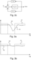
- Figure 2c schematically illustrates a signal diagram according to an example embodiment.
- Injected amount of fuel Qinj is presented by a graph G1.
- Nominal fuel pressure Pnom is presented by a graph G2.
- Figure 3b schematically illustrates a diagram wherein the three parameters of Figure 3a given as a function of time T(s), for comparison reasons.
- Figure 3b is relating to a case where the proposed method is applied.
- values of at least one operational parameter of the combustion engine system is considered, namely the boost pressure Pb and the Lambda-value ⁇ .
- Injected amount of fuel Qinj is presented by a graph G1.
- Nominal fuel pressure Pnom is presented by a graph G2.
- the actual fuel pressure Pr is substantially at the same level as a desired nominal fuel pressure Pnom until fuel injection to the engine 250 is interrupted.
- the interruption of fuel injection is hereby caused by a process of changing gear-steps of the gearbox of the vehicle.
- the actual fuel pressure Pr is only slightly deviating from the nominal fuel pressure Pnom.
- Control routines are hereby based on injected amount of fuel Qinj as well as boost pressure Pb and/or the Lambda-value ⁇ (see e.g. Figure 3b and Figure 4b ).
- the actual fuel pressure Pr is advantageously already at a level of the nominal fuel pressure Pnom.
- FIG. 4a schematically illustrates a flow chart of a method for operating a fuel supply pump 241 of a vehicle 100.
- vehicle 100 comprises a combustion engine system and a gearbox.
- the method comprises a method step s401.
- the method step s401 comprises the steps of:
- the method steps of the step s401 may be performed continuously or intermittently.
- Figure 4b schematically illustrates a flow chart of an exemplified embodiment of a method for operating a fuel supply pump 241 of a vehicle 100. According to one embodiment the method is activated upon detection of propulsion of the vehicle 100.
- the method may comprise a method step s410.
- the method step s410 comprises the step of determining a prevailing fuel pressure Pr. This may be performed by means of a fuel pressure sensor 243.
- the step of determining a prevailing fuel pressure Pr may be performed continuously or intermittently.
- a subsequent method step s420 may be performed.
- the method step s430 may comprise the step of determining a prevailing Lambda-value ⁇ .
- the Lambda-value ⁇ may be determined continuously or intermittently.
- the Lambda-value ⁇ may be determined by means of the Lambda-sensor arrangement 261 and the first control arrangement 200.
- the method step s430 may comprise the step of determining values of at least one operational parameter of the combustion engine system, wherein the operational parameter is the Lambda-value ⁇ . After the method step s430 a subsequent method step s440 may be performed.
- the method step s440 may comprise the step of determining a change of injected amount of fuel Qinj to the engine 250.
- the step of determining a change of injected amount of fuel Qinj may comprise the step of determining if a fuel provision rate is reduced. According to one example a change is determined if a fuel provision rate is reduced by at least 50% from a prevailing fuel provision rate. According to one example a change is determined if a fuel provision rate is reduced by at least 90% from a prevailing fuel provision rate. According to one example a change is determined if fuel provision is reduced to zero (that is, interrupted). This can be performed by means of the first control arrangement 200.
- the method step s440 may comprise the step of determining a change of fuel provision to the combustion engine system. After the method step s440 a subsequent method step s450 may be performed.
- the method step s450 may comprise the step of determining if the thus determined boost pressure Pb is unchanged, given that a change of injected amount of fuel Qinj has been determined.
- the thus determined boost pressure Pb is hereby maintained at a constant level over time when the injected amount of fuel Qinj is changed.
- the thus determined boost pressure Pb is hereby maintained at a constant level over time when the injected amount of fuel Qinj per second is significally reduced, e.g. by 90% or more. If the boost pressure Pb is changed by more than to a predetermined extent, e.g. 10%, 25% or 50%, it is determined that the boost pressure Pr is not unchanged.
- the step s450 may be performed by means of the first control arrangement 200. After the method step s450 a subsequent method step s460 may be performed.
- the method step s460 may comprise the step of determining if the thus determined Lambda-values ⁇ are unchanged, given that a change of injected amount of fuel Qinj has been determined.
- the thus determined Lambda-values ⁇ are hereby maintained at a constant level over time when the injected amount of fuel Qinj is changed.
- the thus determined Lambda-values ⁇ are hereby maintained at a constant level over time when the injected amount of fuel Qinj per second is significally reduced, e.g. by 90% or more. If the Lambda-values ⁇ are changed by more than to a predetermined extent, e.g. 10%, 25% or 50%, it is determined that the Lambda-value ⁇ is not unchanged.
- the step s460 may be performed by means of the first control arrangement 200. After the method step s460 a subsequent method step s470 may be performed.
- the method step s470 may comprise the step of determining whether a gear-step change of the gearbox of the vehicle is at hand. This may be performed by means of the first control arrangement 200.
- the method step s470 may comprise the step of determining whether a gear step change of the gearbox is at hand, on the basis of the thus determined values Pb and ⁇ of the at least one operational parameter.
- the method step s470 may comprise the step of determining that a gear step change of the gearbox is at hand if the boost pressure Pb is unchanged over time.
- the method step s470 may comprise the step of determining that a gear step change of the gearbox is not at hand if the boost pressure Pb is changed more than to a predetermined extent.
- the method step s470 may comprise the step of determining that a gear step change of the gearbox is at hand if the Lambda-value ⁇ is unchanged over time.
- the method step s470 may comprise the step of determining s470 that a gear step change of the gearbox is not at hand if the Lambda-value ⁇ is changed more than to a predetermined extent.
- step change of the gearbox is at hand a subsequent step s480 may be performed.
- the method step s480 may comprise the step of controlling operation of the fuel supply pump 241 so as to maintain fuel supply pump speed Prpm at a current/prevailing level.
- the method step s480 may comprise the step of controlling operation of the fuel supply pump 241 so as to maintain fuel supply pump speed Prpm.
- the actual fuel pressure Pr is maintained at a level of the nominal fuel pressure Pnom (see Fig. 3b ).
- the fuel supply pump speed Prpm may be controlled according to stored routines.
- operation of the feeder pump 241 may be controlled on the basis of the prevailing fuel pressure Pr such that the feeder pump speed Prpm is reduced accordingly if the prevailing fuel pressure Pr is reduced.
- step s480 the method ends/is returned.
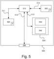
- FIG. 5 is a diagram of one version of a device 500.
- the control arrangements 200 and 210 described with reference to Figure 2 may in one version comprise the device 500.
- the device 500 comprises a non-volatile memory 520, a data processing unit 510 and a read/write memory 550.
- the non-volatile memory 520 has a first memory element 530 in which a computer program, e.g. an operating system, is stored for controlling the function of the device 500.
- the device 500 further comprises a bus controller, a serial communication port, I/O means, an A/D converter, a time and date input and transfer unit, an event counter and an interruption controller (not depicted).
- the non-volatile memory 520 has also a second memory element 540.
- the computer program P comprises routines for operating a fuel supply pump 241 of the vehicle 100.
- the computer program P may comprise routines for determining values of at least one operational parameter of the combustion engine system.
- the computer program P may comprise routines for determining a change of fuel provision to the combustion engine system.
- the computer program P may comprise routines for determining whether a gear step change of the gearbox is at hand, on the basis of the thus determined values of the at least one operational parameter.
- the computer program P may comprise routines for, in case a gear step change of the gearbox is at hand, controlling operation of the fuel supply pump so as to maintain fuel supply pump speed Prpm.
- the computer program P may comprise routines for, in case a gear step change of the gearbox is not at hand, allowing a change of fuel supply pump speed Prpm.
- the computer program P may comprise routines for determining a boost pressure Pb of the combustion engine system and determining that a gear step change of the gearbox is at hand if the boost pressure Pb is unchanged over time.
- the computer program P may comprise routines for determining a boost pressure Pb of the combustion engine system and determining that a gear step change of the gearbox is not at hand if the boost pressure Pb is changed more than to a predetermined extent.
- the computer program P may comprise routines for determining a Lambda-value ⁇ of the combustion engine system and determining that a gear step change of the gearbox is at hand if the Lambda-value ⁇ is unchanged over time.
- the computer program P may comprise routines for determining a Lambda-value ⁇ of the combustion engine system and determining that a gear step change of the gearbox is not at hand if the Lambda-value ⁇ is changed more than to a predetermined extent.
- the computer program P may comprise routines for performing any one of the process steps detailed with reference to the disclosure.
- the program P may be stored in an executable form or in compressed form in a memory 560 and/or in a read/write memory 550.
- the data processing unit 510 performs a certain function, it means that it conducts a certain part of the program which is stored in the memory 560 or a certain part of the program which is stored in the read/write memory 550.
- the data processing device 510 can communicate with a data port 599 via a data bus 515.
- the non-volatile memory 520 is intended for communication with the data processing unit 510 via a data bus 512.
- the separate memory 560 is intended to communicate with the data processing unit via a data bus 511.
- the read/write memory 550 is arranged to communicate with the data processing unit 510 via a data bus 514.
- the links L210, L231, L241, L243, L261 and L271, for example, may be connected to the data port 599 (see Fig. 2a and 2b ).
- Parts of the methods herein described may be conducted by the device 500 by means of the data processing unit 510 which runs the program stored in the memory 560 or the read/write memory 550.
- the device 500 runs the program, method steps and process steps herein described are executed.
Landscapes
- Engineering & Computer Science (AREA)
- Chemical & Material Sciences (AREA)
- Combustion & Propulsion (AREA)
- Mechanical Engineering (AREA)
- General Engineering & Computer Science (AREA)
- Electrical Control Of Air Or Fuel Supplied To Internal-Combustion Engine (AREA)
- Combined Controls Of Internal Combustion Engines (AREA)
- Control Of Vehicle Engines Or Engines For Specific Uses (AREA)
Description
- The present invention relates to a method for operating a fuel supply pump of a vehicle. In particular the present invention relates to controlling a fuel supply pump at a low pressure side of a fuel provision system of a combustion engine. The invention relates also to a computer program product comprising program code for a computer for implementing a method according to the invention. It relates also to a system operating a fuel supply pump of a vehicle and a vehicle equipped with the system.
- Motor vehicles being arranged to be propelled by means of an internal combustion engine are provided with a fuel provision system. According to one variant, a low-pressure fuel circuit of the fuel provision system comprises a feeder pump being arranged to provide fuel to a high pressure pump of the internal combustion engine.
- Some drawbacks have been identified regarding the low-pressure fuel circuit. One of them is appearance of a reduction of fuel pressure in the low-pressure fuel circuit of the fuel provision system during gear shifting. This phenomenon occurs due to that fact that the existing regulation strategy is controlling the feeder pump to reduce its speed when the injected amount of fuel to the engine is reduced, which may happen during dragging of the engine, e.g. when driving downhill, but also during gear shifting. The problem is though that the gear shifting sequence is relatively fast and the feeder pump hereby is not always able to increase its speed fast enough to reach a nominal fuel feed pressure after the shifting is performed.
- The speed of the feeder feed pump is today regulated on the basis of a prevailing fuel pressure downstream of the feeder pump. The feeder pump speed is controlled in such a way that a constant fuel feed pressure is achieved. There is also an input regarding the amount of fuel injected to the engine. The reason for this is that there is a desire to reduce the feeder pump speed during dragging of the engine. However, during gear shifting the injected amount of fuel is also reduced (e.g. to a zero level), but only for a relatively short amount of time. Hereby the feeder pump is arranged to reduce pump speed, but since the time window for a gear shifting is so short, the feeder pump is not able to increase its speed fast enough again when the shifting sequence has been performed. This may cause discomfort for an operator of the vehicle.
- Another issue is that pressure spikes in the fuel provision system occurs during the gear shifting sequence. Since there are so many gear shifting sequences during the life of a truck this can give arise to fatigue problems of the fuel pipes.
-
WO2014189444A1 discloses a method for controlling a low-pressure circuit in fuel system of a vehicle. Hereby controlling of a fuel pump in low-pressure circuit is based on a future working point that is determined based on road ahead information. - The patent application
JP S60 187726 A - An object of the present invention is to propose a novel and advantageous method for operating a fuel supply pump of a vehicle according to claim 1.
- Another object of the invention is to propose a novel and advantageous system according to claim 6 and a novel and advantageous computer program according to claim 12 for operating a fuel supply pump of a vehicle.
- The invention is providing as well a more comfortable operation of the vehicle as a low wear of the components of the fuel supply system and a fully automated and user-friendly operation of a fuel supply pump of a vehicle.
- Hereby a prevailing fuel supply pump speed may be maintained at a current level during a gear shifting process of the gearbox. This advantageously provides a more comfortable propulsion of the vehicle since a stable operation without great variations of fuel supply is achieved. This also provides a fuel supply system which is introducing less wear of components of the fuel supply system.
- Any one of the steps of the method for operating a fuel supply pump of a vehicle may be performed continuously or intermittently.
- By identifying if a gear shifting process of the gearbox is at hand when the injected fuel amount rate is decreased it can be concluded that the vehicle is not dragging. The gear shift process is a relatively short process and advantageously the fuel supply pump rate is not reduced from a current level if a gear step change of the gearbox is at hand.
- The fuel supply pump is arranged in a low-pressure circuit of a fuel supply system. The fuel supply pump may be a feeder pump being arranged to provide fuel to a high pressure pump of a combustion engine.
- Advantageously the proposed method introduces less vehicle vibrations and reduced vehicle noise emissions during a gear step change.
- According to one embodiment it is determined that a gear-step change of the gearbox is at hand if the boost pressure has been determined to be unchanged. According to one embodiment it is determined that a gear-step change of the gearbox is not at hand if the boost pressure has been determined to have changed. According to one embodiment it is determined that a gear-step change of the gearbox is at hand if the Lambda-value has been determined to be unchanged. According to one embodiment it is determined that a gear-step change of the gearbox is not at hand if the Lambda-value has been determined to have changed.
- According to one embodiment it is determined that a gear-step change of the gearbox is at hand if both the Lambda-value and the boost pressure have been determined to be unchanged. According to one embodiment it is determined that a gear-step change of the gearbox is not at hand if both the Lambda-value and the boost pressure have been determined to have changed.
- The system may comprise means being arranged for, in case a gear step change of the gearbox is not at hand, allowing a change of fuel supply pump speed. The means being arranged for allowing a change of fuel supply pump speed may comprise one of one or more electronic control arrangements.
- The means being arranged for determining a boost pressure of the combustion engine system may comprise one or more electronic control arrangements and a boost pressure sensor. The means being arranged for determining that a gear step change of the gearbox is not at hand may comprise one or more electronic control arrangements. The means being arranged for determining a boost pressure may be arranged to determine the boost pressure continuously or intermittently.
- The means being arranged for determining a Lambda-value of the combustion engine system may comprise one or more electronic control arrangements and a Lambda-sensor configuration. The means being arranged for determining that a gear step change of the gearbox is at hand may comprise one or more electronic control arrangements. The means being arranged for determining a Lambda-value may be arranged to determine the Lambda-value continuously or intermittently.
- For fuller understanding of embodiments of the present invention and its further objects and advantages, the detailed description set out below should be read in conjunction with the accompanying drawings, in which the same reference notations denote similar items in the various diagrams, and in which:
-
Figure 1 schematically illustrates a vehicle according to an embodiment of the invention; -
Figure 2a schematically illustrates a system according to an embodiment of the invention; -
Figure 2b schematically illustrates a system according to an embodiment of the invention; -
Figure 2c schematically illustrates a signal scheme according to an embodiment of the invention; -
Figure 3a schematically illustrates a diagram presenting actual fuel pressure of a fuel supply system; -
Figure 3b schematically illustrates a diagram presenting actual fuel pressure of a fuel supply system according to an embodiment of the invention; -
Figure 4a is a schematic flowchart of a method according to an embodiment of the invention; -
Figure 4b is a schematic flowchart of a method according to an embodiment of the invention; and -
Figure 5 schematically illustrates a computer according to an embodiment of the invention. -
Figure 1 depicts a side view of avehicle 100. The exemplifiedvehicle 100 comprises atractor unit 110 and atrailer 112. Thevehicle 100 may be a heavy vehicle, e.g. a truck or a bus. It may alternatively be a car. Thevehicle 100 comprises a combustion engine system and transmission for propelling the vehicle. Thevehicle 100 may comprise an internal combustion engine and a multi-step gearbox. The transmission may comprise a clutch being arranged to disengage the gearbox from an outgoing shaft of the combustion engine during a gear-step change of the gearbox. - The method and system are applicable to various vehicles comprising a combustion engine system and transmission for propelling the vehicle, such as e.g. a mining machine, tractor, dumper, wheel-loader, forest machine, earth mover, road construction vehicle, road planner, emergency vehicle or a tracked vehicle. The method and system disclosed herein is applicable to various stationary platforms comprising a combustion engine system and transmission for conveying torque to any application device/system.
- The term "link" refers herein to a communication link which may be a physical connection such as an opto-electronic communication line, or a non-physical connection such as a wireless connection, e.g. a radio link or microwave link.
- The term "system" is according to one embodiment herein defined as a system comprising only one electronic control arrangement or a number of connected electronic control arrangements. Said one electronic control arrangement or said number of connected electronic control arrangements may be arranged to perform the steps according to the method depicted herein. Herein the term "electronic control arrangement" may be synonymous with an "electronic control unit" (ECU).
- The term "combustion engine system" herein refers to a system comprising a combustion engine. Other components of the combustion engine system may be a turbo (boost) unit, an engine inlet passage, an engine outlet passage, etc. According to one embodiment the combustion engine system also comprises a transmission for propelling the vehicle. The transmission comprises a gearbox (not shown).
-
Figure 2a schematically illustrates afuel supply system 289 of thevehicle 100. Thesystem 289 is situated in thetractor unit 110. - A
first fuel tank 230 is arranged to hold a fuel for provision to anengine 250 of thevehicle 100. Thefirst fuel tank 230 may be referred to as main fuel tank. Theengine 250 may be any suitable engine, such as an internal combustion engine. Theengine 250 may comprise a so called Otto-engine or a diesel engine. The fuel is a fluid. The fuel may be a so-called liquid fuel. The fuel may comprise hydrocarbon fuels, various alcohols and/or bio-diesel. The fuel may be a gaseous fuel. The fuel may be a liquefied petroleum gas. - A
fuel passage configuration 239 is arranged to convey the fuel from thefirst fuel tank 230 via a number of components for provision to theengine 250. A firstelectronic control arrangement 200 is arranged for communication with a firstelectrical fuel pump 231 via a link L231. The firstelectrical fuel pump 231 may be referred to as transfer pump. Thefirst control arrangement 200 is arranged to control operation of the firstelectrical fuel pump 231 by means of control signals S231. The firstelectrical fuel pump 231 is arranged to feed the fuel through afirst filter unit 232. Thefirst filter unit 232 is arranged for water separation and to filter the fuel with regard to larger particles and contamination material. - The
fuel passage configuration 239 is arranged to convey the fuel from thefirst fuel tank 230 to asecond fuel tank 240. Thesecond fuel tank 240 may be referred to as catch tank. The catch tank is preferably smaller than the main tank. The firstelectronic control arrangement 200 is arranged for communication with a secondelectrical fuel pump 241 via a link L241. The secondelectrical fuel pump 241 may be referred to as feeder pump. Thefirst control arrangement 200 is arranged to control operation of the secondelectrical fuel pump 241 by means of control signals 5241. The secondelectrical fuel pump 241 is arranged to feed the fuel through asecond filter unit 242. Thesecond filter unit 242 is arranged to filter the fuel with regard to finer particles and contamination material. - The
feeder pump 241 is arranged to provide the fuel to a high pressure pump (HHP) 245. A portion of thefuel supply system 289 being arranged upstream of thehigh pressure pump 245 is referred to as a low pressure fuel circuitry. Thehigh pressure pump 245 is arranged to provide fuel for controlled injection to combustion chambers of theengine 250. Thefirst control arrangement 200 is arranged to control fuel supply to theengine 250. An injected amount of the fuel is herein denoted Qinj. Thefirst control arrangement 200 may be adapted to control operation of theengine 250 in accordance with stored control routines. - The first
electronic control arrangement 200 is arranged for communication with afuel pressure sensor 243 via a link L243. Thefuel pressure sensor 243 is arranged to measure a prevailing fuel pressure Pr of the fuel within thefuel passage configuration 239 at a position downstream of thesecond filter unit 242 and upstream of a thehigh pressure pump 245. Thefuel pressure sensor 243 is arranged to send signals S243 comprising information about the determined prevailing fuel pressure Pr to thefirst control arrangement 200 via the link L243. - A
second control arrangement 210 is arranged for communication with thefirst control arrangement 200 via a link L210. It may be releasably connected to thefirst control arrangement 200. It may be a control arrangement external to thevehicle 100. It may be adapted to perform the steps according to embodiments of the invention. It may be used to cross-load software to thefirst control arrangement 200, particularly software for applying the method disclosed herein. It may alternatively be arranged for communication with thefirst control arrangement 200 via an internal network on board thevehicle 100. It may be adapted to perform functions corresponding to those of thefirst control arrangement 200, such as determining whether a gear step change of a gearbox of the vehicle is at hand, on the basis of the thus determined values of the at least one operational parameter. It may be adapted to, in case a gear step change of the gearbox is at hand, controlling operation of thefeeder pump 241 so as to maintain the speed Prpm of thefeeder pump 241. -
Figure 2b schematically illustrates a portion of a combustion engine system of thevehicle 100. The combustion engine system may comprise a turbo charger unit (not shown). Thefirst control arrangement 200 is arranged for communication with aboost pressure sensor 271 via a link L271. Theboost pressure sensor 271 is arranged to measure a prevailing boost pressure Pb in an air intake passage of theengine 250. Theboost pressure sensor 271 may be arranged to continuously or intermittently measure a prevailing boost pressure Pb in an air intake passage of the engine 250Theboost pressure sensor 271 is arranged to send signals S271 comprising information about the measured prevailing boost pressure Pb to thefirst control arrangement 200 via the link L271. - The
first control arrangement 200 is arranged for communication with a Lambda-sensor configuration 261 via a link L261. The Lambda-sensor configuration 261 is arranged to determine adequate information for determining a prevailing Lambda-value λ relating to engine operation. Here the Lambda-sensor configuration 261 is arranged in an outlet passage of theengine 250. The Lambda-sensor configuration 261 may be arranged to continuously or intermittently determine a prevailing Lambda-value λ. The Lambda-sensor configuration 261 is arranged to send signals S261 comprising the thus determined adequate information for determining the prevailing Lambda-value λ to thefirst control arrangement 200 via the link L261. The Lambda-value λ is known to relate to an Air Fuel Ratio (AFR). - According to one aspect of the disclosure there is provided a system for operating a
fuel supply pump 241 of avehicle 100, the vehicle comprising acombustion engine system 250 and a gearbox. - According to an example there is provided a system comprising means being arranged for determining values of at least one operational parameter of the
combustion engine system 250. The means being arranged for determining values of at least one operational parameter may comprise any one of thefirst control arrangement 200, thesecond control arrangement 210, the device 500 (Fig. 5 ), theboost pressure sensor 271 and the Lambda-sensor configuration 261. The at least one operational parameter may be the boost pressure Pb of thecombustion engine system 250 and/or the Lambda-value λ of thecombustion engine system 250. - According to an example there is provided a system comprising means being arranged for determining a change of fuel provision to the
combustion engine system 250. The means being arranged for determining a change of fuel provision may comprise any one of thefirst control arrangement 200, thesecond control arrangement 210 and thedevice 500. - According to an example there is provided a system comprising means being arranged for determining whether a gear step change of the gearbox is at hand, on the basis of the thus determined values of the at least one operational parameter. The means being arranged for determining whether a gear step change of the gearbox is at hand may comprise any one of the
first control arrangement 200, thesecond control arrangement 210 and thedevice 500. - According to an example there is provided a system comprising means being arranged for, in case a gear step change of the gearbox is at hand, controlling operation of the
fuel supply pump 241 so as to maintain fuel supply pump speed Prpm. The means being arranged for controlling operation of thefuel supply pump 241 so as to maintain fuel supply pump speed Prpm may comprise any one of thefirst control arrangement 200, thesecond control arrangement 210 and thedevice 500. - According to an example there is provided a system comprising means being arranged for, in case a gear step change of the gearbox is not at hand, allowing a change of fuel supply pump speed Prpm. The means being arranged to allow the change of fuel supply pump speed Prpm may comprise any one of the
first control arrangement 200, thesecond control arrangement 210 and thedevice 500. - According to an example there is provided a system comprising means being arranged for determining a boost pressure Pb of the
combustion engine system 250. The means being arranged for determining a boost pressure Pb may comprise any one of thefirst control arrangement 200, thesecond control arrangement 210, thedevice 500 and theboost pressure sensor 271. - According to an example there is provided a system comprising means being arranged for determining that a gear step change of the gearbox is at hand if the boost pressure Pb is unchanged over time. The means being arranged for determining that a gear step change of the gearbox is at hand may comprise any one of the
first control arrangement 200, thesecond control arrangement 210 and thedevice 500. - According to an example there is provided a system comprising means being arranged for determining that a gear step change of the gearbox is not at hand if the boost pressure Pb is changed more than to a predetermined extent. The means being arranged for determining that a gear step change of the gearbox is not at hand may comprise any one of the
first control arrangement 200, thesecond control arrangement 210 and thedevice 500. - According to an example there is provided a system comprising means being arranged for determining a Lambda-value λ of the
combustion engine system 250. The means being arranged for determining a Lambda-value λ of thecombustion engine system 250 may comprise any one of thefirst control arrangement 200, thesecond control arrangement 210, thedevice 500 and the Lambda-sensor configuration 261. - According to an example there is provided a system comprising means being arranged for determining that a gear step change of the gearbox is at hand if the Lambda-value λ is unchanged over time. The means being arranged for determining that a gear step change of the gearbox is at hand may comprise any one of the
first control arrangement 200, thesecond control arrangement 210 and thedevice 500. - According to an example there is provided a system comprising means being arranged for determining that a gear step change of the gearbox is not at hand if the Lambda-value λ is changed more than to a predetermined extent. The means being arranged for determining that a gear step change of the gearbox is not at hand may comprise any one of the
first control arrangement 200, thesecond control arrangement 210 and thedevice 500. - According to one example there is provided a vehicle comprising a system according to the disclosure herein.
-
Figure 2c schematically illustrates a signal diagram according to an example embodiment. - The speed Prpm of the
feeder pump 241 is operated on the basis of the fuel pressure Pr. A signal relating to the injected amount of fuel Qinj to theengine 250 is provided. Herein a regulator is arrange to provide the feeder pump speed signal on the basis of: - 1) The boost pressure Pb only;
- 2) The Lambda-value λ only;
- 3) Both the boost pressure Pb and the Lambda-value λ.
- Functionality of the signal diagram is depicted in greater detail with reference to e.g.
Figure 4b . -
Figure 3a schematically illustrates a diagram wherein three parameters are given as a function of time T(s).Figure 3a is relating to a case where the proposed method is not applied. - Injected amount of fuel Qinj is presented by a graph G1.
- Nominal fuel pressure Pnom is presented by a graph G2.
- Actual fuel pressure Pr is presented by a graph G3.
- Herein it is illustrated that the actual fuel pressure Pr is at the same level as a desired nominal fuel pressure Pnom until fuel injection to the
engine 250 is interrupted. The interruption of fuel injection may be caused by a process of changing gear-steps of the gearbox of the vehicle. Hereby the actual fuel pressure Pr is reduced according to control routines based on injected amount of fuel Qinj. At a point of time where the gear shifting process of the gearbox is completed the actual fuel pressure Pr is built up and later stabilised at a level of the nominal fuel pressure Pnom. - According to this control procedure an undesired drop of fuel pressure Pr is appearing during resuming of fuel provision after an interruption.
-
Figure 3b schematically illustrates a diagram wherein the three parameters ofFigure 3a given as a function of time T(s), for comparison reasons.Figure 3b is relating to a case where the proposed method is applied. Hereby values of at least one operational parameter of the combustion engine system is considered, namely the boost pressure Pb and the Lambda-value λ. - Injected amount of fuel Qinj is presented by a graph G1.
- Nominal fuel pressure Pnom is presented by a graph G2.
- Actual fuel pressure Pr is presented by a graph G3.
- Herein it is illustrated that the actual fuel pressure Pr is substantially at the same level as a desired nominal fuel pressure Pnom until fuel injection to the
engine 250 is interrupted. The interruption of fuel injection is hereby caused by a process of changing gear-steps of the gearbox of the vehicle. Hereby the actual fuel pressure Pr is only slightly deviating from the nominal fuel pressure Pnom. Control routines are hereby based on injected amount of fuel Qinj as well as boost pressure Pb and/or the Lambda-value λ (see e.g.Figure 3b andFigure 4b ). At a point of time where the gear shifting process of the gearbox is completed, the actual fuel pressure Pr is advantageously already at a level of the nominal fuel pressure Pnom. - According to this control procedure, where the proposed method is applied, substantially no (undesired) drop of the fuel pressure Pr is appearing during fuel provision interruption.
-
Figure 4a schematically illustrates a flow chart of a method for operating afuel supply pump 241 of avehicle 100. Thevehicle 100 comprises a combustion engine system and a gearbox. The method comprises a method step s401. The method step s401 comprises the steps of: - determining values of at least one operational parameter of the combustion engine system;
- determining a reduction of fuel a provision rate to the combustion engine system;
- determining whether a gear step change of the gearbox is at hand, on the basis of the thus determined values of the at least one operational parameter; and
- in case a gear step change of the gearbox is at hand, controlling operation of the
fuel supply pump 241 so as to maintain fuel supply pump speed Prpm. - The method steps of the step s401 may be performed continuously or intermittently.
- After the method step s401 the method ends/is returned.
-
Figure 4b schematically illustrates a flow chart of an exemplified embodiment of a method for operating afuel supply pump 241 of avehicle 100. According to one embodiment the method is activated upon detection of propulsion of thevehicle 100. - The method may comprise a method step s410. The method step s410 comprises the step of determining a prevailing fuel pressure Pr. This may be performed by means of a
fuel pressure sensor 243. The step of determining a prevailing fuel pressure Pr may be performed continuously or intermittently. After the method step s410 a subsequent method step s420 may be performed. - The method step s420 may comprise the step of determining a boost pressure Pb provided by a turbo charger unit of the
engine 250. The turbo charger unit may also be denoted turbo arrangement. The boost pressure Pb may alternatively be denoted charge air pressure. The boost pressure Pb may be determined continuously or intermittently. The boost pressure Pb may be determined by means of theboost pressure sensor 271. The method step s420 may comprise the step of determining values of at least one operational parameter of the combustion engine system, wherein the operational parameter is the boost pressure Pb. According to one example, wherein the combustion engine system does not comprise a turbo charger unit, the method step s420 is not performed. Hereby the proposed method is performed on the basis of a determined prevailing Lambda-value λ (see step s430). After the method step s420 a subsequent method step s430 may be performed. - The method step s430 may comprise the step of determining a prevailing Lambda-value λ. The Lambda-value λ may be determined continuously or intermittently. The Lambda-value λ may be determined by means of the Lambda-
sensor arrangement 261 and thefirst control arrangement 200. The method step s430 may comprise the step of determining values of at least one operational parameter of the combustion engine system, wherein the operational parameter is the Lambda-value λ. After the method step s430 a subsequent method step s440 may be performed. - The method step s440 may comprise the step of determining a change of injected amount of fuel Qinj to the
engine 250. The step of determining a change of injected amount of fuel Qinj may comprise the step of determining if a fuel provision rate is reduced. According to one example a change is determined if a fuel provision rate is reduced by at least 50% from a prevailing fuel provision rate. According to one example a change is determined if a fuel provision rate is reduced by at least 90% from a prevailing fuel provision rate. According to one example a change is determined if fuel provision is reduced to zero (that is, interrupted). This can be performed by means of thefirst control arrangement 200. The method step s440 may comprise the step of determining a change of fuel provision to the combustion engine system. After the method step s440 a subsequent method step s450 may be performed. - The method step s450 may comprise the step of determining if the thus determined boost pressure Pb is unchanged, given that a change of injected amount of fuel Qinj has been determined. The thus determined boost pressure Pb is hereby maintained at a constant level over time when the injected amount of fuel Qinj is changed. The thus determined boost pressure Pb is hereby maintained at a constant level over time when the injected amount of fuel Qinj per second is significally reduced, e.g. by 90% or more. If the boost pressure Pb is changed by more than to a predetermined extent, e.g. 10%, 25% or 50%, it is determined that the boost pressure Pr is not unchanged. The step s450 may be performed by means of the
first control arrangement 200. After the method step s450 a subsequent method step s460 may be performed. - The method step s460 may comprise the step of determining if the thus determined Lambda-values λ are unchanged, given that a change of injected amount of fuel Qinj has been determined. The thus determined Lambda-values λ are hereby maintained at a constant level over time when the injected amount of fuel Qinj is changed. The thus determined Lambda-values λ are hereby maintained at a constant level over time when the injected amount of fuel Qinj per second is significally reduced, e.g. by 90% or more. If the Lambda-values λ are changed by more than to a predetermined extent, e.g. 10%, 25% or 50%, it is determined that the Lambda-value λ is not unchanged. The step s460 may be performed by means of the
first control arrangement 200. After the method step s460 a subsequent method step s470 may be performed. - The method step s470 may comprise the step of determining whether a gear-step change of the gearbox of the vehicle is at hand. This may be performed by means of the
first control arrangement 200. - The method step s470 may comprise the step of determining whether a gear step change of the gearbox is at hand, on the basis of the thus determined values Pb and λ of the at least one operational parameter.
- The method step s470 may comprise the step of determining that a gear step change of the gearbox is at hand if the boost pressure Pb is unchanged over time.
- The method step s470 may comprise the step of determining that a gear step change of the gearbox is not at hand if the boost pressure Pb is changed more than to a predetermined extent.
- The method step s470 may comprise the step of determining that a gear step change of the gearbox is at hand if the Lambda-value λ is unchanged over time.
- The method step s470 may comprise the step of determining s470 that a gear step change of the gearbox is not at hand if the Lambda-value λ is changed more than to a predetermined extent.
- If it is determined that gear step change of the gearbox is at hand a subsequent step s480 may be performed.
- If it is determined that a gear step change of the gearbox is not at hand a change of fuel supply pump speed Prpm is allowed.
- The method step s480 may comprise the step of controlling operation of the
fuel supply pump 241 so as to maintain fuel supply pump speed Prpm at a current/prevailing level. The method step s480 may comprise the step of controlling operation of thefuel supply pump 241 so as to maintain fuel supply pump speed Prpm. Hereby the actual fuel pressure Pr is maintained at a level of the nominal fuel pressure Pnom (seeFig. 3b ). - In case a gear step change of the gearbox is not at hand the fuel supply pump speed Prpm may be controlled according to stored routines. Hereby operation of the
feeder pump 241 may be controlled on the basis of the prevailing fuel pressure Pr such that the feeder pump speed Prpm is reduced accordingly if the prevailing fuel pressure Pr is reduced. - After the method step s480 the method ends/is returned.
-
Figure 5 is a diagram of one version of adevice 500. Thecontrol arrangements Figure 2 may in one version comprise thedevice 500. Thedevice 500 comprises anon-volatile memory 520, adata processing unit 510 and a read/write memory 550. Thenon-volatile memory 520 has afirst memory element 530 in which a computer program, e.g. an operating system, is stored for controlling the function of thedevice 500. Thedevice 500 further comprises a bus controller, a serial communication port, I/O means, an A/D converter, a time and date input and transfer unit, an event counter and an interruption controller (not depicted). Thenon-volatile memory 520 has also asecond memory element 540. - The computer program P comprises routines for operating a
fuel supply pump 241 of thevehicle 100. - The computer program P may comprise routines for determining values of at least one operational parameter of the combustion engine system.
- The computer program P may comprise routines for determining a change of fuel provision to the combustion engine system.
- The computer program P may comprise routines for determining whether a gear step change of the gearbox is at hand, on the basis of the thus determined values of the at least one operational parameter.
- The computer program P may comprise routines for, in case a gear step change of the gearbox is at hand, controlling operation of the fuel supply pump so as to maintain fuel supply pump speed Prpm.
- The computer program P may comprise routines for, in case a gear step change of the gearbox is not at hand, allowing a change of fuel supply pump speed Prpm.
- The computer program P may comprise routines for determining a boost pressure Pb of the combustion engine system and determining that a gear step change of the gearbox is at hand if the boost pressure Pb is unchanged over time.
- The computer program P may comprise routines for determining a boost pressure Pb of the combustion engine system and determining that a gear step change of the gearbox is not at hand if the boost pressure Pb is changed more than to a predetermined extent.
- The computer program P may comprise routines for determining a Lambda-value λ of the combustion engine system and determining that a gear step change of the gearbox is at hand if the Lambda-value λ is unchanged over time.
- The computer program P may comprise routines for determining a Lambda-value λ of the combustion engine system and determining that a gear step change of the gearbox is not at hand if the Lambda-value λ is changed more than to a predetermined extent.
- The computer program P may comprise routines for performing any one of the process steps detailed with reference to the disclosure.
- The program P may be stored in an executable form or in compressed form in a
memory 560 and/or in a read/write memory 550. - Where it is stated that the
data processing unit 510 performs a certain function, it means that it conducts a certain part of the program which is stored in thememory 560 or a certain part of the program which is stored in the read/write memory 550. - The
data processing device 510 can communicate with adata port 599 via adata bus 515. Thenon-volatile memory 520 is intended for communication with thedata processing unit 510 via adata bus 512. Theseparate memory 560 is intended to communicate with the data processing unit via adata bus 511. The read/write memory 550 is arranged to communicate with thedata processing unit 510 via adata bus 514. The links L210, L231, L241, L243, L261 and L271, for example, may be connected to the data port 599 (seeFig. 2a and 2b ). - When data are received on the
data port 599, they are stored temporarily in thesecond memory element 540. When input data received have been temporarily stored, thedata processing unit 510 will be prepared to conduct code execution as described above. - Parts of the methods herein described may be conducted by the
device 500 by means of thedata processing unit 510 which runs the program stored in thememory 560 or the read/write memory 550. When thedevice 500 runs the program, method steps and process steps herein described are executed. - The foregoing description of the preferred embodiments of the present invention is provided for illustrative and descriptive purposes. It is not intended to be exhaustive, nor to limit the invention to the variants described.
Claims (13)
- A method for operating a fuel supply pump (241) of a vehicle (100), the vehicle (100) comprising a combustion engine system (250) and a gearbox, the method comprising the steps of:- determining (s420; s430) values (Pb; λ) of at least one operational parameter of the combustion engine system (250), wherein the at least one operational parameter is a boost pressure (Pb) of the combustion engine system (250) and/or a Lambda-value (λ) of the combustion engine system (250);- determining (s440) a reduction of a fuel provision rate to the combustion engine system (250);- determining (s470) whether a gear step change of the gearbox is at hand, on the basis of the thus determined values (Pb; λ) of the at least one operational parameter;- in case a gear step change of the gearbox is at hand, controlling (s480) operation of the fuel supply pump (241) so as to maintain fuel supply pump speed (Prpm); and- in case a gear step change of the gearbox is not at hand, allowing a change of fuel supply pump speed (Prpm).
- The method according to claim 1, comprising the steps of:- determining (s420) a boost pressure (Pb) of the combustion engine system (250); and- determining (s470) that a gear step change of the gearbox is at hand if the boost pressure (Pb) is unchanged over time.
- The method according to any one of the preceding claims, comprising the steps of:- determining (s420) a boost pressure (Pb) of the combustion engine system (250); and- determining (s470) that a gear step change of the gearbox is not at hand if the boost pressure (Pb) is changed more than to a predetermined extent.
- The method according to any one of the preceding claims, comprising the steps of:- determining (s430) a Lambda-value (λ) of the combustion engine system (250); and- determining (s470) that a gear step change of the gearbox is at hand if the Lambda-value (λ) is unchanged over time.
- The method according to any one of the preceding claims, comprising the steps of:- determining (s430) a Lambda-value (λ) of the combustion engine system (250); and- determining (s470) that a gear step change of the gearbox is not at hand if the Lambda-value (λ) is changed more than to a predetermined extent.
- A system for operating a fuel supply pump (241) of a vehicle (100), the vehicle (100) comprising a combustion engine system (250) and a gearbox, the system comprises:- means (200; 210; 500; 261, 271) being arranged for determining values (Pb; λ) of at least one operational parameter of the combustion engine system (250), wherein the at least one operational parameter is a boost pressure (Pb) of the combustion engine system (250) and/or a Lambda-value (λ) of the combustion engine system (250);- means (200; 210; 500) being arranged for determining a reduction of a fuel provision rate to the combustion engine system (250);- means (200; 210; 500) being arranged for determining whether a gear step change of the gearbox is at hand, on the basis of the thus determined values (Pb; λ) of the at least one operational parameter;- means (200; 210; 500) being arranged for, in case a gear step change of the gearbox is at hand, controlling operation of the fuel supply pump (241) so as to maintain fuel supply pump speed (Prpm); and- means (200; 210; 500) being arranged for, in case a gear step change of the gearbox is not at hand, allowing a change of fuel supply pump speed (Prpm).
- The system according to claim 6, the system comprising:- means (200; 210; 500) being arranged for determining a boost pressure (Pb) of the combustion engine system (250); and- means (200; 210; 500) being arranged for determining that a gear step change of the gearbox is at hand if the boost pressure (Pb) is unchanged over time.
- The system according to any one of the claims 6-7, the system comprising:- means (200; 210; 500) being arranged for determining a boost pressure (Pb) of the combustion engine system (250); and- means (200; 210; 500) being arranged for determining that a gear step change of the gearbox is not at hand if the boost pressure (Pb) is changed more than to a predetermined extent.
- The system according to any one of the claims 6-8, the system comprising:- means (200; 210; 500) being arranged for determining a Lambda-value (λ) of the combustion engine system (250); and- means (200; 210; 500) being arranged for determining that a gear step change of the gearbox is at hand if the Lambda-value (λ) is unchanged over time.
- The system according to any one of the claims 6-9, the system comprising:- means (200; 210; 500) being arranged for determining a Lambda-value (λ) of the combustion engine system (250); and- means (200; 210; 500) being arranged for determining that a gear step change of the gearbox is not at hand if the Lambda-value (λ) is changed more than to a predetermined extent.
- A vehicle (100; 110) comprising a system according to any one of the claims 6-10.
- A computer program product comprising instructions which, when the program is executed by a computer (200; 210), cause the computer (200; 210; 500) to carry out the steps of the method according to any one of the claims 1-5 in a system according to any one of the claims 6-10.
- A computer-readable storage medium having stored thereon the computer program product of claim 12.
Applications Claiming Priority (2)
| Application Number | Priority Date | Filing Date | Title |
|---|---|---|---|
| SE1951369A SE543784C2 (en) | 2019-11-29 | 2019-11-29 | System and method for operating a fuel supply pump of a vehicle |
| PCT/SE2020/051112 WO2021107837A1 (en) | 2019-11-29 | 2020-11-23 | System and method for operating a fuel supply pump of a vehicle |
Publications (3)
| Publication Number | Publication Date |
|---|---|
| EP4065830A1 EP4065830A1 (en) | 2022-10-05 |
| EP4065830A4 EP4065830A4 (en) | 2023-12-27 |
| EP4065830B1 true EP4065830B1 (en) | 2025-01-08 |
Family
ID=76129931
Family Applications (1)
| Application Number | Title | Priority Date | Filing Date |
|---|---|---|---|
| EP20891939.9A Active EP4065830B1 (en) | 2019-11-29 | 2020-11-23 | System and method for operating a fuel supply pump of a vehicle |
Country Status (6)
| Country | Link |
|---|---|
| US (1) | US11698038B2 (en) |
| EP (1) | EP4065830B1 (en) |
| CN (1) | CN114729607B (en) |
| BR (1) | BR112022008724A2 (en) |
| SE (1) | SE543784C2 (en) |
| WO (1) | WO2021107837A1 (en) |
Family Cites Families (25)
| Publication number | Priority date | Publication date | Assignee | Title |
|---|---|---|---|---|
| JPS60147564A (en) * | 1984-01-13 | 1985-08-03 | Toyota Motor Corp | Fuel pump controller for fuel injection type engine |
| JPS60187726A (en) * | 1984-03-06 | 1985-09-25 | Toyota Motor Corp | Fuel injection device of engine |
| JPH0681931B2 (en) * | 1986-06-25 | 1994-10-19 | 日本電装株式会社 | Fuel pump controller |
| EP0724686B1 (en) * | 1993-10-21 | 2001-04-04 | Orbital Engine Company (Australia) Pty. Ltd. | Control of fuelling rate of an engine |
| US5505180A (en) * | 1995-03-31 | 1996-04-09 | Ford Motor Company | Returnless fuel delivery mechanism with adaptive learning |
| JPH109074A (en) * | 1996-06-26 | 1998-01-13 | Nissan Motor Co Ltd | Direct in-cylinder injection spark ignition engine |
| JP2000345886A (en) * | 1999-05-31 | 2000-12-12 | Isuzu Motors Ltd | Fuel injection control device for diesel engine |
| WO2003023232A2 (en) | 2001-09-10 | 2003-03-20 | Stanadyne Corporation | Hybrid demand control for hydraulic pump |
| US20090090331A1 (en) * | 2007-10-04 | 2009-04-09 | Ford Global Technologies, Llc | Volumetric Efficiency Based Lift Pump Control |
| DE102007060216A1 (en) * | 2007-12-14 | 2009-06-18 | Robert Bosch Gmbh | Method for operating a spark-ignited internal combustion engine |
| SE532715C2 (en) * | 2008-06-18 | 2010-03-23 | Scania Cv Abp | Method and system for transmission control at low power demand |
| WO2012040610A2 (en) * | 2010-09-23 | 2012-03-29 | Cummins Intellectual Property, Inc. | Variable flow fuel transfer pump system and method |
| JP5682221B2 (en) * | 2010-10-15 | 2015-03-11 | 日産自動車株式会社 | Engine fuel pump control device |
| US8473147B2 (en) * | 2011-03-23 | 2013-06-25 | GM Global Technology Operations LLC | State of health indicator for a vehicle fuel delivery system |
| JP5927817B2 (en) | 2011-09-14 | 2016-06-01 | 日産自動車株式会社 | Vehicle drive device |
| SE536319C2 (en) * | 2011-12-13 | 2013-08-20 | Scania Cv Ab | Device and method for fault detection in a fuel supply system of a motor vehicle |
| SE536640C2 (en) * | 2012-06-27 | 2014-04-22 | Scania Cv Ab | Process for controlling a vehicle's drive system, drive system, computer program, computer software product and vehicle |
| EP2870351B1 (en) * | 2012-07-05 | 2018-04-25 | United Technologies Corporation | Fuel preheating using electric pump |
| US9903306B2 (en) * | 2013-02-08 | 2018-02-27 | Cummins Inc. | System and method for acquiring pressure data from a fuel accumulator of an internal combustion engine |
| SE538376C2 (en) * | 2013-05-23 | 2016-06-07 | Scania Cv Ab | Method and system for controlling a low pressure circuit in a fuel system of a vehicle |
| JP6380446B2 (en) * | 2016-03-30 | 2018-08-29 | トヨタ自動車株式会社 | Vehicle control device |
| SE1650871A1 (en) * | 2016-06-21 | 2017-12-22 | Scania Cv Ab | Method and system for controlling the amount of fuel in connection to operating an internal combustion engine |
| US10174704B2 (en) * | 2016-10-21 | 2019-01-08 | Ford Global Technologies, Llc | Systems and methods for controlling a fuel pump in start/stop and hybrid electric vehicles |
| JP6521019B2 (en) * | 2017-10-03 | 2019-05-29 | マツダ株式会社 | Control device for a vehicle with multistage automatic transmission |
| US10508612B2 (en) * | 2018-03-23 | 2019-12-17 | Ford Global Technologies, Llc | System and methods for operating fuel system responsive to inferred fuel temperature |
-
2019
- 2019-11-29 SE SE1951369A patent/SE543784C2/en unknown
-
2020
- 2020-11-23 US US17/777,133 patent/US11698038B2/en active Active
- 2020-11-23 BR BR112022008724A patent/BR112022008724A2/en unknown
- 2020-11-23 CN CN202080080645.4A patent/CN114729607B/en active Active
- 2020-11-23 EP EP20891939.9A patent/EP4065830B1/en active Active
- 2020-11-23 WO PCT/SE2020/051112 patent/WO2021107837A1/en not_active Ceased
Also Published As
| Publication number | Publication date |
|---|---|
| US11698038B2 (en) | 2023-07-11 |
| BR112022008724A2 (en) | 2022-07-19 |
| CN114729607A (en) | 2022-07-08 |
| SE1951369A1 (en) | 2021-05-30 |
| EP4065830A4 (en) | 2023-12-27 |
| SE543784C2 (en) | 2021-07-20 |
| EP4065830A1 (en) | 2022-10-05 |
| WO2021107837A1 (en) | 2021-06-03 |
| CN114729607B (en) | 2024-08-27 |
| US20220389880A1 (en) | 2022-12-08 |
Similar Documents
| Publication | Publication Date | Title |
|---|---|---|
| US8484971B2 (en) | Method of operating a vehicle equipped with a pneumatic booster system | |
| US8666634B2 (en) | Method of operating a vehicle equipped with a pneumatic booster system | |
| US8505297B2 (en) | Method of operating a vehicle equipped with a pneumatic booster system | |
| US8412424B2 (en) | Vehicle pneumatic booster system operating method and apparatus | |
| US8468824B2 (en) | Method of operating a vehicle equipped with a pneumatic booster system | |
| US9376978B2 (en) | Method when driving a vehicle and a computer program for this, a system for implementing the method and a vehicle comprising the system | |
| US20110288715A1 (en) | Vehicle Pneumatic Booster System Operating Method and Apparatus | |
| WO2011146496A1 (en) | Vehicle pneumatic booster system operating method and apparatus | |
| WO2011146500A1 (en) | Vehicle pneumatic booster system operating method and apparatus | |
| CN101149114B (en) | Power transmission system for vehicle and control method therefor | |
| WO2009154559A1 (en) | Method and system for transmission control at low power requirement | |
| KR102039566B1 (en) | A method when driving a vehicle and swithching to higher gear, a computer program for the method, a system enabling the method and a vehicle for it | |
| EP4065830B1 (en) | System and method for operating a fuel supply pump of a vehicle | |
| WO2012121657A1 (en) | Method and device for control of pumping work of a combustion engine | |
| EP3400157B1 (en) | A method and a system for improved gear shifting of a transmission | |
| WO2017119835A1 (en) | A system and a method for improved take-off of a vehicle | |
| EP2612015B1 (en) | Method for control of a damper for regulating a flow in a pipe connected to an engine |
Legal Events
| Date | Code | Title | Description |
|---|---|---|---|
| STAA | Information on the status of an ep patent application or granted ep patent |
Free format text: STATUS: THE INTERNATIONAL PUBLICATION HAS BEEN MADE |
|
| PUAI | Public reference made under article 153(3) epc to a published international application that has entered the european phase |
Free format text: ORIGINAL CODE: 0009012 |
|
| STAA | Information on the status of an ep patent application or granted ep patent |
Free format text: STATUS: REQUEST FOR EXAMINATION WAS MADE |
|
| 17P | Request for examination filed |
Effective date: 20220629 |
|
| AK | Designated contracting states |
Kind code of ref document: A1 Designated state(s): AL AT BE BG CH CY CZ DE DK EE ES FI FR GB GR HR HU IE IS IT LI LT LU LV MC MK MT NL NO PL PT RO RS SE SI SK SM TR |
|
| DAV | Request for validation of the european patent (deleted) | ||
| DAX | Request for extension of the european patent (deleted) | ||
| P01 | Opt-out of the competence of the unified patent court (upc) registered |
Effective date: 20230518 |
|
| A4 | Supplementary search report drawn up and despatched |
Effective date: 20231124 |
|
| RIC1 | Information provided on ipc code assigned before grant |
Ipc: F02D 41/14 20060101ALN20231120BHEP Ipc: F02D 41/00 20060101ALN20231120BHEP Ipc: F02D 41/38 20060101ALI20231120BHEP Ipc: F02D 33/00 20060101ALI20231120BHEP Ipc: F02M 37/08 20060101ALI20231120BHEP Ipc: F02D 41/30 20060101ALI20231120BHEP Ipc: F02D 41/02 20060101AFI20231120BHEP |
|
| GRAP | Despatch of communication of intention to grant a patent |
Free format text: ORIGINAL CODE: EPIDOSNIGR1 |
|
| STAA | Information on the status of an ep patent application or granted ep patent |
Free format text: STATUS: GRANT OF PATENT IS INTENDED |
|
| RIC1 | Information provided on ipc code assigned before grant |
Ipc: F02D 41/14 20060101ALN20240611BHEP Ipc: F02D 41/00 20060101ALN20240611BHEP Ipc: F02D 41/38 20060101ALI20240611BHEP Ipc: F02D 33/00 20060101ALI20240611BHEP Ipc: F02M 37/08 20060101ALI20240611BHEP Ipc: F02D 41/30 20060101ALI20240611BHEP Ipc: F02D 41/02 20060101AFI20240611BHEP |
|
| RIC1 | Information provided on ipc code assigned before grant |
Ipc: F02D 41/14 20060101ALN20240620BHEP Ipc: F02D 41/00 20060101ALN20240620BHEP Ipc: F02D 41/38 20060101ALI20240620BHEP Ipc: F02D 33/00 20060101ALI20240620BHEP Ipc: F02M 37/08 20060101ALI20240620BHEP Ipc: F02D 41/30 20060101ALI20240620BHEP Ipc: F02D 41/02 20060101AFI20240620BHEP |
|
| INTG | Intention to grant announced |
Effective date: 20240701 |
|
| GRAS | Grant fee paid |
Free format text: ORIGINAL CODE: EPIDOSNIGR3 |
|
| GRAA | (expected) grant |
Free format text: ORIGINAL CODE: 0009210 |
|
| STAA | Information on the status of an ep patent application or granted ep patent |
Free format text: STATUS: THE PATENT HAS BEEN GRANTED |
|
| AK | Designated contracting states |
Kind code of ref document: B1 Designated state(s): AL AT BE BG CH CY CZ DE DK EE ES FI FR GB GR HR HU IE IS IT LI LT LU LV MC MK MT NL NO PL PT RO RS SE SI SK SM TR |
|
| REG | Reference to a national code |
Ref country code: GB Ref legal event code: FG4D |
|
| REG | Reference to a national code |
Ref country code: CH Ref legal event code: EP |
|
| REG | Reference to a national code |
Ref country code: DE Ref legal event code: R096 Ref document number: 602020044657 Country of ref document: DE |
|
| REG | Reference to a national code |
Ref country code: IE Ref legal event code: FG4D |
|
| REG | Reference to a national code |
Ref country code: LT Ref legal event code: MG9D |
|
| REG | Reference to a national code |
Ref country code: NL Ref legal event code: MP Effective date: 20250108 |
|
| REG | Reference to a national code |
Ref country code: AT Ref legal event code: MK05 Ref document number: 1758466 Country of ref document: AT Kind code of ref document: T Effective date: 20250108 |
|
| PG25 | Lapsed in a contracting state [announced via postgrant information from national office to epo] |
Ref country code: NL Free format text: LAPSE BECAUSE OF FAILURE TO SUBMIT A TRANSLATION OF THE DESCRIPTION OR TO PAY THE FEE WITHIN THE PRESCRIBED TIME-LIMIT Effective date: 20250108 |
|
| PG25 | Lapsed in a contracting state [announced via postgrant information from national office to epo] |
Ref country code: RS Free format text: LAPSE BECAUSE OF FAILURE TO SUBMIT A TRANSLATION OF THE DESCRIPTION OR TO PAY THE FEE WITHIN THE PRESCRIBED TIME-LIMIT Effective date: 20250408 |
|
| PG25 | Lapsed in a contracting state [announced via postgrant information from national office to epo] |
Ref country code: FI Free format text: LAPSE BECAUSE OF FAILURE TO SUBMIT A TRANSLATION OF THE DESCRIPTION OR TO PAY THE FEE WITHIN THE PRESCRIBED TIME-LIMIT Effective date: 20250108 |
|
| PG25 | Lapsed in a contracting state [announced via postgrant information from national office to epo] |
Ref country code: PL Free format text: LAPSE BECAUSE OF FAILURE TO SUBMIT A TRANSLATION OF THE DESCRIPTION OR TO PAY THE FEE WITHIN THE PRESCRIBED TIME-LIMIT Effective date: 20250108 |
|
| PG25 | Lapsed in a contracting state [announced via postgrant information from national office to epo] |
Ref country code: ES Free format text: LAPSE BECAUSE OF FAILURE TO SUBMIT A TRANSLATION OF THE DESCRIPTION OR TO PAY THE FEE WITHIN THE PRESCRIBED TIME-LIMIT Effective date: 20250108 |
|
| PG25 | Lapsed in a contracting state [announced via postgrant information from national office to epo] |
Ref country code: IS Free format text: LAPSE BECAUSE OF FAILURE TO SUBMIT A TRANSLATION OF THE DESCRIPTION OR TO PAY THE FEE WITHIN THE PRESCRIBED TIME-LIMIT Effective date: 20250508 Ref country code: NO Free format text: LAPSE BECAUSE OF FAILURE TO SUBMIT A TRANSLATION OF THE DESCRIPTION OR TO PAY THE FEE WITHIN THE PRESCRIBED TIME-LIMIT Effective date: 20250408 |
|
| PG25 | Lapsed in a contracting state [announced via postgrant information from national office to epo] |
Ref country code: HR Free format text: LAPSE BECAUSE OF FAILURE TO SUBMIT A TRANSLATION OF THE DESCRIPTION OR TO PAY THE FEE WITHIN THE PRESCRIBED TIME-LIMIT Effective date: 20250108 |
|
| PG25 | Lapsed in a contracting state [announced via postgrant information from national office to epo] |
Ref country code: PT Free format text: LAPSE BECAUSE OF FAILURE TO SUBMIT A TRANSLATION OF THE DESCRIPTION OR TO PAY THE FEE WITHIN THE PRESCRIBED TIME-LIMIT Effective date: 20250508 Ref country code: LV Free format text: LAPSE BECAUSE OF FAILURE TO SUBMIT A TRANSLATION OF THE DESCRIPTION OR TO PAY THE FEE WITHIN THE PRESCRIBED TIME-LIMIT Effective date: 20250108 |
|
| PG25 | Lapsed in a contracting state [announced via postgrant information from national office to epo] |
Ref country code: GR Free format text: LAPSE BECAUSE OF FAILURE TO SUBMIT A TRANSLATION OF THE DESCRIPTION OR TO PAY THE FEE WITHIN THE PRESCRIBED TIME-LIMIT Effective date: 20250409 Ref country code: BG Free format text: LAPSE BECAUSE OF FAILURE TO SUBMIT A TRANSLATION OF THE DESCRIPTION OR TO PAY THE FEE WITHIN THE PRESCRIBED TIME-LIMIT Effective date: 20250108 |
|
| PG25 | Lapsed in a contracting state [announced via postgrant information from national office to epo] |
Ref country code: AT Free format text: LAPSE BECAUSE OF FAILURE TO SUBMIT A TRANSLATION OF THE DESCRIPTION OR TO PAY THE FEE WITHIN THE PRESCRIBED TIME-LIMIT Effective date: 20250108 |
|
| PG25 | Lapsed in a contracting state [announced via postgrant information from national office to epo] |
Ref country code: SE Free format text: LAPSE BECAUSE OF FAILURE TO SUBMIT A TRANSLATION OF THE DESCRIPTION OR TO PAY THE FEE WITHIN THE PRESCRIBED TIME-LIMIT Effective date: 20250108 |
|
| PG25 | Lapsed in a contracting state [announced via postgrant information from national office to epo] |
Ref country code: SM Free format text: LAPSE BECAUSE OF FAILURE TO SUBMIT A TRANSLATION OF THE DESCRIPTION OR TO PAY THE FEE WITHIN THE PRESCRIBED TIME-LIMIT Effective date: 20250108 |
|
| REG | Reference to a national code |
Ref country code: DE Ref legal event code: R097 Ref document number: 602020044657 Country of ref document: DE |
|
| PG25 | Lapsed in a contracting state [announced via postgrant information from national office to epo] |
Ref country code: DK Free format text: LAPSE BECAUSE OF FAILURE TO SUBMIT A TRANSLATION OF THE DESCRIPTION OR TO PAY THE FEE WITHIN THE PRESCRIBED TIME-LIMIT Effective date: 20250108 |
|
| PGFP | Annual fee paid to national office [announced via postgrant information from national office to epo] |
Ref country code: FR Payment date: 20250930 Year of fee payment: 6 |
|
| PG25 | Lapsed in a contracting state [announced via postgrant information from national office to epo] |
Ref country code: CZ Free format text: LAPSE BECAUSE OF FAILURE TO SUBMIT A TRANSLATION OF THE DESCRIPTION OR TO PAY THE FEE WITHIN THE PRESCRIBED TIME-LIMIT Effective date: 20250108 Ref country code: EE Free format text: LAPSE BECAUSE OF FAILURE TO SUBMIT A TRANSLATION OF THE DESCRIPTION OR TO PAY THE FEE WITHIN THE PRESCRIBED TIME-LIMIT Effective date: 20250108 |
|
| PG25 | Lapsed in a contracting state [announced via postgrant information from national office to epo] |
Ref country code: RO Free format text: LAPSE BECAUSE OF FAILURE TO SUBMIT A TRANSLATION OF THE DESCRIPTION OR TO PAY THE FEE WITHIN THE PRESCRIBED TIME-LIMIT Effective date: 20250108 |
|
| PG25 | Lapsed in a contracting state [announced via postgrant information from national office to epo] |
Ref country code: SK Free format text: LAPSE BECAUSE OF FAILURE TO SUBMIT A TRANSLATION OF THE DESCRIPTION OR TO PAY THE FEE WITHIN THE PRESCRIBED TIME-LIMIT Effective date: 20250108 |
|
| PLBE | No opposition filed within time limit |
Free format text: ORIGINAL CODE: 0009261 |
|
| STAA | Information on the status of an ep patent application or granted ep patent |
Free format text: STATUS: NO OPPOSITION FILED WITHIN TIME LIMIT |
|
| 26N | No opposition filed |
Effective date: 20251009 |
|
| PGFP | Annual fee paid to national office [announced via postgrant information from national office to epo] |
Ref country code: DE Payment date: 20250930 Year of fee payment: 6 |
|
| PGFP | Annual fee paid to national office [announced via postgrant information from national office to epo] |
Ref country code: GB Payment date: 20251001 Year of fee payment: 6 |
|
| PGFP | Annual fee paid to national office [announced via postgrant information from national office to epo] |
Ref country code: BE Payment date: 20251003 Year of fee payment: 6 |
|
| PG25 | Lapsed in a contracting state [announced via postgrant information from national office to epo] |
Ref country code: IT Free format text: LAPSE BECAUSE OF FAILURE TO SUBMIT A TRANSLATION OF THE DESCRIPTION OR TO PAY THE FEE WITHIN THE PRESCRIBED TIME-LIMIT Effective date: 20250108 |