EP4065750B1 - Assessing a flow of a sprayed coating - Google Patents
Assessing a flow of a sprayed coating Download PDFInfo
- Publication number
- EP4065750B1 EP4065750B1 EP20807400.5A EP20807400A EP4065750B1 EP 4065750 B1 EP4065750 B1 EP 4065750B1 EP 20807400 A EP20807400 A EP 20807400A EP 4065750 B1 EP4065750 B1 EP 4065750B1
- Authority
- EP
- European Patent Office
- Prior art keywords
- tracer
- image
- coating
- tracer particles
- flow parameter
- Prior art date
- Legal status (The legal status is an assumption and is not a legal conclusion. Google has not performed a legal analysis and makes no representation as to the accuracy of the status listed.)
- Active
Links
Images

Classifications
-
- G—PHYSICS
- G01—MEASURING; TESTING
- G01F—MEASURING VOLUME, VOLUME FLOW, MASS FLOW OR LIQUID LEVEL; METERING BY VOLUME
- G01F1/00—Measuring the volume flow or mass flow of fluid or fluent solid material wherein the fluid passes through a meter in a continuous flow
- G01F1/704—Measuring the volume flow or mass flow of fluid or fluent solid material wherein the fluid passes through a meter in a continuous flow using marked regions or existing inhomogeneities within the fluid stream, e.g. statistically occurring variations in a fluid parameter
- G01F1/708—Measuring the time taken to traverse a fixed distance
- G01F1/7086—Measuring the time taken to traverse a fixed distance using optical detecting arrangements
-
- G—PHYSICS
- G01—MEASURING; TESTING
- G01N—INVESTIGATING OR ANALYSING MATERIALS BY DETERMINING THEIR CHEMICAL OR PHYSICAL PROPERTIES
- G01N11/00—Investigating flow properties of materials, e.g. viscosity, plasticity; Analysing materials by determining flow properties
-
- C—CHEMISTRY; METALLURGY
- C23—COATING METALLIC MATERIAL; COATING MATERIAL WITH METALLIC MATERIAL; CHEMICAL SURFACE TREATMENT; DIFFUSION TREATMENT OF METALLIC MATERIAL; COATING BY VACUUM EVAPORATION, BY SPUTTERING, BY ION IMPLANTATION OR BY CHEMICAL VAPOUR DEPOSITION, IN GENERAL; INHIBITING CORROSION OF METALLIC MATERIAL OR INCRUSTATION IN GENERAL
- C23C—COATING METALLIC MATERIAL; COATING MATERIAL WITH METALLIC MATERIAL; SURFACE TREATMENT OF METALLIC MATERIAL BY DIFFUSION INTO THE SURFACE, BY CHEMICAL CONVERSION OR SUBSTITUTION; COATING BY VACUUM EVAPORATION, BY SPUTTERING, BY ION IMPLANTATION OR BY CHEMICAL VAPOUR DEPOSITION, IN GENERAL
- C23C24/00—Coating starting from inorganic powder
-
- C—CHEMISTRY; METALLURGY
- C23—COATING METALLIC MATERIAL; COATING MATERIAL WITH METALLIC MATERIAL; CHEMICAL SURFACE TREATMENT; DIFFUSION TREATMENT OF METALLIC MATERIAL; COATING BY VACUUM EVAPORATION, BY SPUTTERING, BY ION IMPLANTATION OR BY CHEMICAL VAPOUR DEPOSITION, IN GENERAL; INHIBITING CORROSION OF METALLIC MATERIAL OR INCRUSTATION IN GENERAL
- C23C—COATING METALLIC MATERIAL; COATING MATERIAL WITH METALLIC MATERIAL; SURFACE TREATMENT OF METALLIC MATERIAL BY DIFFUSION INTO THE SURFACE, BY CHEMICAL CONVERSION OR SUBSTITUTION; COATING BY VACUUM EVAPORATION, BY SPUTTERING, BY ION IMPLANTATION OR BY CHEMICAL VAPOUR DEPOSITION, IN GENERAL
- C23C4/00—Coating by spraying the coating material in the molten state, e.g. by flame, plasma or electric discharge
-
- G—PHYSICS
- G01—MEASURING; TESTING
- G01F—MEASURING VOLUME, VOLUME FLOW, MASS FLOW OR LIQUID LEVEL; METERING BY VOLUME
- G01F1/00—Measuring the volume flow or mass flow of fluid or fluent solid material wherein the fluid passes through a meter in a continuous flow
- G01F1/704—Measuring the volume flow or mass flow of fluid or fluent solid material wherein the fluid passes through a meter in a continuous flow using marked regions or existing inhomogeneities within the fluid stream, e.g. statistically occurring variations in a fluid parameter
-
- G—PHYSICS
- G01—MEASURING; TESTING
- G01N—INVESTIGATING OR ANALYSING MATERIALS BY DETERMINING THEIR CHEMICAL OR PHYSICAL PROPERTIES
- G01N21/00—Investigating or analysing materials by the use of optical means, i.e. using sub-millimetre waves, infrared, visible or ultraviolet light
- G01N21/84—Systems specially adapted for particular applications
- G01N21/8422—Investigating thin films, e.g. matrix isolation method
-
- G—PHYSICS
- G01—MEASURING; TESTING
- G01P—MEASURING LINEAR OR ANGULAR SPEED, ACCELERATION, DECELERATION, OR SHOCK; INDICATING PRESENCE, ABSENCE, OR DIRECTION, OF MOVEMENT
- G01P13/00—Indicating or recording presence, absence, or direction, of movement
- G01P13/0093—Indicating or recording presence, absence, or direction, of movement by making use of products, e.g. chemical products added to the fluid in order to make the fluid flow visible
-
- G—PHYSICS
- G01—MEASURING; TESTING
- G01P—MEASURING LINEAR OR ANGULAR SPEED, ACCELERATION, DECELERATION, OR SHOCK; INDICATING PRESENCE, ABSENCE, OR DIRECTION, OF MOVEMENT
- G01P5/00—Measuring speed of fluids, e.g. of air stream; Measuring speed of bodies relative to fluids, e.g. of ship, of aircraft
- G01P5/18—Measuring speed of fluids, e.g. of air stream; Measuring speed of bodies relative to fluids, e.g. of ship, of aircraft by measuring the time taken to traverse a fixed distance
- G01P5/20—Measuring speed of fluids, e.g. of air stream; Measuring speed of bodies relative to fluids, e.g. of ship, of aircraft by measuring the time taken to traverse a fixed distance using particles entrained by a fluid stream
-
- G—PHYSICS
- G06—COMPUTING OR CALCULATING; COUNTING
- G06T—IMAGE DATA PROCESSING OR GENERATION, IN GENERAL
- G06T7/00—Image analysis
- G06T7/0002—Inspection of images, e.g. flaw detection
- G06T7/0004—Industrial image inspection
- G06T7/001—Industrial image inspection using an image reference approach
-
- G—PHYSICS
- G01—MEASURING; TESTING
- G01N—INVESTIGATING OR ANALYSING MATERIALS BY DETERMINING THEIR CHEMICAL OR PHYSICAL PROPERTIES
- G01N11/00—Investigating flow properties of materials, e.g. viscosity, plasticity; Analysing materials by determining flow properties
- G01N2011/006—Determining flow properties indirectly by measuring other parameters of the system
- G01N2011/008—Determining flow properties indirectly by measuring other parameters of the system optical properties
-
- G—PHYSICS
- G01—MEASURING; TESTING
- G01N—INVESTIGATING OR ANALYSING MATERIALS BY DETERMINING THEIR CHEMICAL OR PHYSICAL PROPERTIES
- G01N21/00—Investigating or analysing materials by the use of optical means, i.e. using sub-millimetre waves, infrared, visible or ultraviolet light
- G01N21/84—Systems specially adapted for particular applications
- G01N21/8422—Investigating thin films, e.g. matrix isolation method
- G01N2021/8427—Coatings
-
- G—PHYSICS
- G01—MEASURING; TESTING
- G01N—INVESTIGATING OR ANALYSING MATERIALS BY DETERMINING THEIR CHEMICAL OR PHYSICAL PROPERTIES
- G01N33/00—Investigating or analysing materials by specific methods not covered by groups G01N1/00 - G01N31/00
- G01N33/20—Metals
- G01N33/208—Coatings, e.g. platings
-
- G—PHYSICS
- G06—COMPUTING OR CALCULATING; COUNTING
- G06T—IMAGE DATA PROCESSING OR GENERATION, IN GENERAL
- G06T2207/00—Indexing scheme for image analysis or image enhancement
- G06T2207/30—Subject of image; Context of image processing
- G06T2207/30108—Industrial image inspection
- G06T2207/30156—Vehicle coating
Definitions
- the invention relates to a method for assessing a flow of a sprayed coating.
- the method comprises the steps of spraying a coating onto a surface and capturing a plurality of images of the sprayed surface at a predetermined frequency within a predetermined interval of time.
- the invention further relates to a computer program product for assessing a flow of a sprayed coating.
- the coating may provide a device with an intended color or texture on the one hand.
- the coating may prevent the device from wear and, in particular, from corrosion in case the surface of the device is made from a corrosive material like a metal. Both effects are particularly important in car manufacturing where most of car body parts are coated.
- a surface is usually coated by spraying a liquid coating onto the surface.
- the coating initially contains a volatile solvent rendering the coating liquid for spraying. After having been sprayed onto the surface the solvent gradually evaporates from the sprayed coating causing the coating to set on the surface. Finally, the coating may be cured by applying an ultraviolet light and/or a heat to the sprayed coating.
- a quality of a coated surface depends on two parameters of the coating called sagging and leveling.
- Sagging indicates the ability of adjacent layers of the coating to displace relative to each other. The higher the sagging of the coating is the less the layers of the coating adhere to each other and, as a consequence, the worse the coating is.
- Leveling indicates a smoothness of a surface of the coating. The higher the leveling of the coating is the smoother the surface of the coating is and, as a consequence, the better the coating is. Thus, a coating having a low sagging and a high leveling is aimed at.
- the sprayed coating is exposed to a gravity continuously during gradual evaporation of the solvent.
- the gravity may and usually does cause the still liquid coating to flow on the surface when setting, wherein the coating flows in a direction defined by a shape of the surface and an orientation of the surface relative to the gravity.
- the gravity thus, may easily deteriorate a quality of the coating by causing a sagging of the sprayed coating and preventing the sprayed coating from leveling.
- One aspect of the invention is a method for assessing a flow of a sprayed coating, comprising the steps of spraying a coating onto a surface, capturing a plurality of images of the sprayed surface at a predetermined frequency within a predetermined interval of time.
- the plurality of images form an ordered sequence of images representing a temporal change of the sprayed coating during the predetermined interval of time.
- the method comprises the steps of providing a coating with a plurality of tracer particles, spraying the provided coating onto a surface, processing each captured image and deriving at least one flow parameter of the sprayed coating from tracer particles imaged by the plurality of processed images.
- the tracer particles are added to the coating for the assessment only, i.e. the tracer particles are not an original component of the coating.
- a color, a reflectivity, a size and the like of the tracer particles may be chosen to render the tracer particles visually distinguishable from the coating.
- the tracer particles are driven by the flowing sprayed coating.
- the tracer particles must not be chosen to move relative to the sprayed coating on their own in order to obtain an accurate result of the assessment.
- each image is captured by a camera with an optical axis extending onto the coated surface.
- the position and the orientation of the camera support capturing images of the sprayed surface.
- a white board having a line pattern is illuminated by a white light source and the white board is reflected by the sprayed surface parallel to the optical axis of the camera.
- the captured image comprises the reflected line pattern in form of relatively darker regions.
- the line pattern may comprise a plurality of lines, particularly a plurality of parallel lines, more particularly a plurality of parallel lines being arranged at equal distances.
- the line pattern may comprise a grid, i.e. a plurality of crossing lines, particularly a regular rectangular grid having a plurality of equally spaced parallel lines extending perpendicular to another plurality of equally spaced parallel lines.
- the reflected line pattern supports a localization of tracer particles within a captured image.
- processing each image comprises highlighting at least one tracer particle in the image.
- the highlighting may comprise increasing a contrast of the image, coloring the at least one tracer particle differently, increasing a size of the at least one tracer particle in the image and the like.
- the highlighting may be considered as a part of a preprocessing of the image and facilitates an automatic recognition of the at least one tracer particle.
- Processing each image may comprise using an existing software tool for image processing. Accordingly, image processing may be carried out by means of standard software without any need for dedicated customization.
- deriving at least one flow parameter comprises recognizing at least one tracer particle in the image by applying a pattern recognition algorithm.
- the tracer particles appear to be discrete pointlike objects in the image which differ from the surrounding coating. As a consequence, the tracer particles may be easily recognized by means of pattern recognition.
- Deriving at least one flow parameter preferably comprises determining a position of at least one tracer particle in each image.
- the position may be determined by image coordinates or, if applicable, by coordinates defined by the line pattern.
- a time dependency of the position of the at least one tracer particle is derived as the at least one flow parameter.
- the time dependency of the position is derived by analyzing the ordered sequence of images and identifying the at least one tracer particle and its possibly varying position in each image.
- Time dependencies of positions of a plurality of tracer particles are advantageously averaged with respect to the tracer particles and the averaged time dependency of positions is derived as the at least one flow parameter.
- the averaging may be accomplished with respect to a plurality of tracer particles in the same orderd sequence of images and/or with respect to a plurality of tracer particles in different ordered sequences of images.
- the averaged time dependency may provide a higher reliability than the positional time dependency of a single tracer particle.
- deriving at least one flow parameter may comprise determining a velocity of at least one tracer particle in the plurality of images.
- the velocity may be calculated, i.e. approximated, by multiplying the positional difference of the tracer particle in successive images with the predetermined frequency.
- a time dependency of the velocity of the at least one tracer particle is derived as the at least one flow parameter.
- the time dependency of the velocity is derived by analyzing the ordered sequence of images and identifying the at least one tracer particle and its possibly varying velocity in each image.
- Time dependencies of velocities of a plurality of tracer particles are advantageously averaged with respect to the tracer particles and the averaged time dependency of velocities is derived as the at least one flow parameter.
- the averaged time dependency may provide a higher reliability than the time dependency of a single tracer particle.
- the predetermined interval of time is in a range from 300 s to 1000 s, preferably in a range from 450 s to 625 s and most preferably is 500 s and/or the predetermined frequency is in a range from 0,05 s -1 to 1 s -1 , preferably in a range from 0,1 s -1 to 0,5 s -1 and most preferably is 0,2 s -1 .
- the method is carried out by a processor executing a program code implementing the method. In this way assessing the flow of the sprayed coating may be automated at least partially which increases an efficiency and accuracy of the assessing process.
- Another aspect of the invention is a computer program product for assessing a flow of a sprayed coating, comprising a data carrier storing a program code to be executed by a processor.
- the data carrier may be used for installing the stored program code and/or for upgrading an installed program code with the stored program code.
- the program code implements an inventive method.
- the stored program code enables for efficiently assessing of a sagging and/or leveling of a coating and, thus, optimizing a quality of coating.
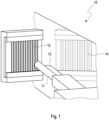
- Fig. 1 schematically shows a perspective view of an arrangement 10 for carrying out a method according to an embodiment of the invention.
- the arrangement 10 comprises a sprayed surface 14 and a camera 13 with an optical axis extending onto the sprayed surface 14, i.e. the camera 13 is directed to the sprayed surface 14.
- the arrangement 10 may further comprise a white board 12 having a line pattern and a light source 11 being arranged for illuminating the white board 12.
- the camera 13, the sprayed surface 14 and the white board 12 are preferably arranged relative to each other such that the line pattern of the white board 12 is reflected by the sprayed surface 14 parallel to the optical axis of the camera 13 into the camera 13.
- the line pattern may comprise a plurality of equally spaced parallel lines or preferably a rectangular grid of equally spaced parallel lines (see fig. 2 and 3 ).
- a flow of the sprayed coating is assessed by applying the following method steps.
- a coating is provided with a plurality of tracer particles and sprayed onto the surface 14. Then the camera 13 captures a plurality of images 20 of the sprayed surface 14 at a predetermined frequency within a predetermined interval of time.
- the predetermined interval of time may be in a range from 300 s to 1000 s, preferably in a range from 450 s to 625 s and exemplarily is 500 s.
- the predetermined frequency may be in a range from 0,05 s -1 to 1 s -1 , preferably in a range from 0,1 s -1 to 0,5 s -1 and exemplarily is 0,2 s -1 .
- Fig. 2 schematically shows schematically an image 20 captured in a method according to an embodiment of the invention.
- the image 20 comprises a plurality of point-like tracer particles 22 and a reflected rectangular grid 21 of equally spaced parallel lines.
- Each captured image 20 is processed by using an existing software tool for image processing. Processing each image 20 may comprise highlighting at least one tracer particle 22, preferably a plurality of tracer particles 22 in the image 20.
- Fig. 3 schematically shows schematically a processed image 30 corresponding to the captured image 20 shown in figure 2 .
- the image comprises a plurality of highlighted tracer particles 32 and the rectangular grid 31 of lines.
- At least one flow parameter of the sprayed coating is derived from the plurality of tracer particles 32 imaged by the plurality of processed images 30. Deriving the at least one flow parameter comprises recognizing a plurality of tracer particles 32 in the image 30 by applying a pattern recognition algorithm. Deriving the at least one flow parameter further comprises determining respective positions 43 of the plurality of tracer particles 32 in each image 30.
- the positions 43 of the tracer particles 32 may be determined with respect to the grid 31 or to a coordinate system of the image 30, i.e. in image coordinates.
- a time dependency of the positions 43 of the plurality of tracer particles 32 may be derived as a first flow parameter from the plurality of processed images 30.
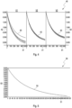
- Fig. 4 shows a graph 40 of positions 43 of tracer particles 32.
- the graph 40 comprises three segments V1, V2, V3 and may be considered to represent a first sagging profile of the sprayed coating.
- Each segment has an abscissa 41 indicating times of the images 30 and an ordinate 42 indicating sagging positions 43 of the tracer particles 32.
- the abscissas 41 cover a time interval of 500 s, respectively.
- the ordinates 42 cover positions in a range from 0 mm to 3 mm.
- the segments V1, V2 illustrate sagging positions of 5 tracer particles 32 while the segment V3 illustrates sagging positions of 6 tracer particles 32.
- Time dependencies of the positions 43 of the plurality of tracer particles 32 may be averaged with respect to the tracer particles 32 and the averaged time dependency of positions may be derived as a second flow parameter.
- Fig. 5 shows a graph 50 of averaged positions 53 of tracer particles 32.
- the graph 50 has an abscissa 51 indicating times of the images 30 and an ordinate 52 indicating averaged sagging positions 53 of the tracer particles 32.
- the abscissa 51 covers a time interval of 500 s.
- the ordinate 52 covers sagging positions in a range from 0 mm to 2,8 mm.
- Deriving at least one flow parameter may further comprise determining velocities 63 of the plurality of tracer particle 32 in the plurality of images 30.
- a time dependency of the velocities 63 of the plurality of tracer particles 32 may be derived as a third flow parameter.
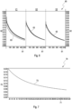
- Fig. 6 shows a graph 60 of velocities 63 of tracer particles 32.
- the graph 60 comprises three segments V1, V2, V3 and may be considered to represent a second sagging profile of the sprayed coating.
- Each segment has an abscissa 61 indicating times of the images 30 and an ordinate 62 indicating sagging velocities 63 of the tracer particles 32.
- the abscissas 61 cover a time interval of 500 s, respectively.
- the ordinates 62 cover velocities in a range from 0,03 mms -1 to 0 mms -1 .
- the segments V1, V2 illustrates sagging velocities 63 of 5 tracer particles 32 while the segment V3 illustrates sagging velocities 63 of 6 tracer particles 32. It can be observed from graph 60 that the sagging velocities 63 of the tracer particles 32 and the respective sagging velocity variations decrease as the coating sets. Another observation is a velocity spread between the tracer particles 32.
- Time dependencies of velocities 63 of a plurality of tracer particles 32 may be averaged with respect to the tracer particles 32 and the averaged time dependency of velocities 63 may be derived as a fourth flow parameter.
- Fig. 7 shows a graph 70 of averaged velocities 73 of tracer particles 32.
- the graph 70 has an abscissa 71 indicating times of the images 30 and an ordinate 72 indicating averaged sagging velocities 73 of the tracer particles 32.
- the abscissa 71 covers a time interval of 500 s.
- the ordinate 72 covers sagging velocities in a range from 0,02 mms -1 to 0 mms -1 .
- the method is preferably carried out by a processor executing a program code implementing the method wherein the program code may be stored on a data carrier of a computer program product for assessing a flow of a sprayed coating and have been installed from the data carrier.
Landscapes
- Physics & Mathematics (AREA)
- Chemical & Material Sciences (AREA)
- General Physics & Mathematics (AREA)
- Engineering & Computer Science (AREA)
- Fluid Mechanics (AREA)
- Chemical Kinetics & Catalysis (AREA)
- Health & Medical Sciences (AREA)
- Life Sciences & Earth Sciences (AREA)
- Immunology (AREA)
- Analytical Chemistry (AREA)
- Biochemistry (AREA)
- General Health & Medical Sciences (AREA)
- Pathology (AREA)
- Organic Chemistry (AREA)
- Metallurgy (AREA)
- Mechanical Engineering (AREA)
- Materials Engineering (AREA)
- General Chemical & Material Sciences (AREA)
- Aviation & Aerospace Engineering (AREA)
- Plasma & Fusion (AREA)
- Mathematical Physics (AREA)
- Quality & Reliability (AREA)
- Computer Vision & Pattern Recognition (AREA)
- Theoretical Computer Science (AREA)
- Food Science & Technology (AREA)
- Medicinal Chemistry (AREA)
- Application Of Or Painting With Fluid Materials (AREA)
- Coating By Spraying Or Casting (AREA)
- Coating Apparatus (AREA)
- Investigating Materials By The Use Of Optical Means Adapted For Particular Applications (AREA)
Description
- The invention relates to a method for assessing a flow of a sprayed coating. The method comprises the steps of spraying a coating onto a surface and capturing a plurality of images of the sprayed surface at a predetermined frequency within a predetermined interval of time. The invention further relates to a computer program product for assessing a flow of a sprayed coating.
- Surfaces of devices are coated mostly for aesthetic and protective reasons. The coating may provide a device with an intended color or texture on the one hand. On the other hand the coating may prevent the device from wear and, in particular, from corrosion in case the surface of the device is made from a corrosive material like a metal. Both effects are particularly important in car manufacturing where most of car body parts are coated.
- A surface is usually coated by spraying a liquid coating onto the surface. The coating initially contains a volatile solvent rendering the coating liquid for spraying. After having been sprayed onto the surface the solvent gradually evaporates from the sprayed coating causing the coating to set on the surface. Finally, the coating may be cured by applying an ultraviolet light and/or a heat to the sprayed coating.
- A quality of a coated surface depends on two parameters of the coating called sagging and leveling. Sagging indicates the ability of adjacent layers of the coating to displace relative to each other. The higher the sagging of the coating is the less the layers of the coating adhere to each other and, as a consequence, the worse the coating is. Leveling indicates a smoothness of a surface of the coating. The higher the leveling of the coating is the smoother the surface of the coating is and, as a consequence, the better the coating is. Thus, a coating having a low sagging and a high leveling is aimed at.
- However, the sprayed coating is exposed to a gravity continuously during gradual evaporation of the solvent. The gravity may and usually does cause the still liquid coating to flow on the surface when setting, wherein the coating flows in a direction defined by a shape of the surface and an orientation of the surface relative to the gravity.
- The gravity, thus, may easily deteriorate a quality of the coating by causing a sagging of the sprayed coating and preventing the sprayed coating from leveling.
- It is therefore an object of the invention to propose a method for assessing a flow of a sprayed coating which assessment allows for reducing a sagging of the coating and increasing a leveling of the coating. Another object of the invention is to provide a computer program product for assessing a flow of a sprayed coating.
- One aspect of the invention is a method for assessing a flow of a sprayed coating, comprising the steps of spraying a coating onto a surface, capturing a plurality of images of the sprayed surface at a predetermined frequency within a predetermined interval of time. The plurality of images form an ordered sequence of images representing a temporal change of the sprayed coating during the predetermined interval of time.
- According to the invention, the method comprises the steps of providing a coating with a plurality of tracer particles, spraying the provided coating onto a surface, processing each captured image and deriving at least one flow parameter of the sprayed coating from tracer particles imaged by the plurality of processed images. The tracer particles are added to the coating for the assessment only, i.e. the tracer particles are not an original component of the coating.
- A color, a reflectivity, a size and the like of the tracer particles may be chosen to render the tracer particles visually distinguishable from the coating. When the sprayed coating flows on the surface the tracer particles are driven by the flowing sprayed coating. The tracer particles must not be chosen to move relative to the sprayed coating on their own in order to obtain an accurate result of the assessment.
- In a preferred embodiment each image is captured by a camera with an optical axis extending onto the coated surface. In other words, the position and the orientation of the camera support capturing images of the sprayed surface.
- Advantageously, a white board having a line pattern is illuminated by a white light source and the white board is reflected by the sprayed surface parallel to the optical axis of the camera. In other words, the captured image comprises the reflected line pattern in form of relatively darker regions. The line pattern may comprise a plurality of lines, particularly a plurality of parallel lines, more particularly a plurality of parallel lines being arranged at equal distances. Alternatively, the line pattern may comprise a grid, i.e. a plurality of crossing lines, particularly a regular rectangular grid having a plurality of equally spaced parallel lines extending perpendicular to another plurality of equally spaced parallel lines. The reflected line pattern supports a localization of tracer particles within a captured image.
- It is preferred that processing each image comprises highlighting at least one tracer particle in the image. The highlighting may comprise increasing a contrast of the image, coloring the at least one tracer particle differently, increasing a size of the at least one tracer particle in the image and the like. The highlighting may be considered as a part of a preprocessing of the image and facilitates an automatic recognition of the at least one tracer particle.
- Processing each image may comprise using an existing software tool for image processing. Accordingly, image processing may be carried out by means of standard software without any need for dedicated customization.
- In advantageous embodiments deriving at least one flow parameter comprises recognizing at least one tracer particle in the image by applying a pattern recognition algorithm. The tracer particles appear to be discrete pointlike objects in the image which differ from the surrounding coating. As a consequence, the tracer particles may be easily recognized by means of pattern recognition.
- Deriving at least one flow parameter preferably comprises determining a position of at least one tracer particle in each image. The position may be determined by image coordinates or, if applicable, by coordinates defined by the line pattern.
- In further embodiments a time dependency of the position of the at least one tracer particle is derived as the at least one flow parameter. The time dependency of the position is derived by analyzing the ordered sequence of images and identifying the at least one tracer particle and its possibly varying position in each image.
- Time dependencies of positions of a plurality of tracer particles are advantageously averaged with respect to the tracer particles and the averaged time dependency of positions is derived as the at least one flow parameter.
- Thereby the averaging may be accomplished with respect to a plurality of tracer particles in the same orderd sequence of images and/or with respect to a plurality of tracer particles in different ordered sequences of images. The averaged time dependency may provide a higher reliability than the positional time dependency of a single tracer particle.
- Alternatively or additionally, deriving at least one flow parameter may comprise determining a velocity of at least one tracer particle in the plurality of images. The velocity may be calculated, i.e. approximated, by multiplying the positional difference of the tracer particle in successive images with the predetermined frequency.
- In still further embodiments a time dependency of the velocity of the at least one tracer particle is derived as the at least one flow parameter. The time dependency of the velocity is derived by analyzing the ordered sequence of images and identifying the at least one tracer particle and its possibly varying velocity in each image.
- Time dependencies of velocities of a plurality of tracer particles are advantageously averaged with respect to the tracer particles and the averaged time dependency of velocities is derived as the at least one flow parameter. The averaged time dependency may provide a higher reliability than the time dependency of a single tracer particle.
- In many embodiments the predetermined interval of time is in a range from 300 s to 1000 s, preferably in a range from 450 s to 625 s and most preferably is 500 s and/or the predetermined frequency is in a range from 0,05 s-1 to 1 s-1, preferably in a range from 0,1 s-1 to 0,5 s-1 and most preferably is 0,2 s-1. For example, it is preferred to capture 100 images within 500 s.
- In many embodiments the method is carried out by a processor executing a program code implementing the method. In this way assessing the flow of the sprayed coating may be automated at least partially which increases an efficiency and accuracy of the assessing process.
- Another aspect of the invention is a computer program product for assessing a flow of a sprayed coating, comprising a data carrier storing a program code to be executed by a processor. The data carrier may be used for installing the stored program code and/or for upgrading an installed program code with the stored program code.
- According to the invention, the program code implements an inventive method. The stored program code enables for efficiently assessing of a sagging and/or leveling of a coating and, thus, optimizing a quality of coating.
- It is an essential advantage of the method according to the invention that a flow of a sprayed coating is assessed very easily and precisely. The method allows for deriving different flow parameters of the sprayed coating by using a simple arrangement of existing devices and established algorithms of image processing.
- Further advantages and configurations of the invention become apparent from the following description and the enclosed drawings.
- It shall be understood that the features described previously and to be described subsequently may be used not only in the indicated combinations but also in different combinations or on their own without leaving the scope of the present invention.
-
- Fig. 1
- schematically shows a perspective view of an arrangement for carrying out a method according to an embodiment of the invention;
- Fig. 2
- schematically shows schematically an image captured in a method according to an embodiment of the invention;
- Fig. 3
- schematically shows schematically the processed image corresponding to the captured image shown in
figure 2 ; - Fig. 4
- shows a graph of positions of tracer particles;
- Fig. 5
- shows a graph of averaged positions of tracer particles;
- Fig. 6
- shows a graph of velocities of tracer particles;
- Fig. 7
- shows a graph of averaged velocities of tracer particles.
-
Fig. 1 schematically shows a perspective view of anarrangement 10 for carrying out a method according to an embodiment of the invention. Thearrangement 10 comprises a sprayedsurface 14 and acamera 13 with an optical axis extending onto the sprayedsurface 14, i.e. thecamera 13 is directed to the sprayedsurface 14. Thearrangement 10 may further comprise awhite board 12 having a line pattern and alight source 11 being arranged for illuminating thewhite board 12. - The
camera 13, the sprayedsurface 14 and thewhite board 12 are preferably arranged relative to each other such that the line pattern of thewhite board 12 is reflected by the sprayedsurface 14 parallel to the optical axis of thecamera 13 into thecamera 13. The line pattern may comprise a plurality of equally spaced parallel lines or preferably a rectangular grid of equally spaced parallel lines (seefig. 2 and 3 ). - A flow of the sprayed coating is assessed by applying the following method steps. A coating is provided with a plurality of tracer particles and sprayed onto the
surface 14. Then thecamera 13 captures a plurality ofimages 20 of the sprayedsurface 14 at a predetermined frequency within a predetermined interval of time. - The predetermined interval of time may be in a range from 300 s to 1000 s, preferably in a range from 450 s to 625 s and exemplarily is 500 s. The predetermined frequency may be in a range from 0,05 s-1 to 1 s-1, preferably in a range from 0,1 s-1 to 0,5 s-1 and exemplarily is 0,2 s-1. The captured
images 20, thus, form an ordered sequence ofimages 20. -
Fig. 2 schematically shows schematically animage 20 captured in a method according to an embodiment of the invention. Theimage 20 comprises a plurality of point-like tracer particles 22 and a reflectedrectangular grid 21 of equally spaced parallel lines. - Each captured
image 20 is processed by using an existing software tool for image processing. Processing eachimage 20 may comprise highlighting at least onetracer particle 22, preferably a plurality oftracer particles 22 in theimage 20. -
Fig. 3 schematically shows schematically a processedimage 30 corresponding to the capturedimage 20 shown infigure 2 . The image comprises a plurality of highlightedtracer particles 32 and therectangular grid 31 of lines. - At least one flow parameter of the sprayed coating is derived from the plurality of
tracer particles 32 imaged by the plurality of processedimages 30. Deriving the at least one flow parameter comprises recognizing a plurality oftracer particles 32 in theimage 30 by applying a pattern recognition algorithm. Deriving the at least one flow parameter further comprises determiningrespective positions 43 of the plurality oftracer particles 32 in eachimage 30. - The
positions 43 of thetracer particles 32 may be determined with respect to thegrid 31 or to a coordinate system of theimage 30, i.e. in image coordinates. - A time dependency of the
positions 43 of the plurality oftracer particles 32 may be derived as a first flow parameter from the plurality of processedimages 30. -
Fig. 4 shows agraph 40 ofpositions 43 oftracer particles 32. Thegraph 40 comprises three segments V1, V2, V3 and may be considered to represent a first sagging profile of the sprayed coating. Each segment has anabscissa 41 indicating times of theimages 30 and anordinate 42 indicating sagging positions 43 of thetracer particles 32. Theabscissas 41 cover a time interval of 500 s, respectively. Theordinates 42 cover positions in a range from 0 mm to 3 mm. The segments V1, V2 illustrate sagging positions of 5tracer particles 32 while the segment V3 illustrates sagging positions of 6tracer particles 32. It can be observed fromgraph 40 that thepositions 43 of thetracer particles 32 sag, i.e.get lower, starting from a position which is shown by thefirst image 30 and equally set to zero for eachtracer particle 32 and that the respective positional variations decrease as the coating sets. Another observation is a positional spread between thetracer particles 32. - Time dependencies of the
positions 43 of the plurality oftracer particles 32 may be averaged with respect to thetracer particles 32 and the averaged time dependency of positions may be derived as a second flow parameter. -
Fig. 5 shows agraph 50 of averagedpositions 53 oftracer particles 32. Thegraph 50 has anabscissa 51 indicating times of theimages 30 and anordinate 52 indicating averaged saggingpositions 53 of thetracer particles 32. Theabscissa 51 covers a time interval of 500 s. Theordinate 52 covers sagging positions in a range from 0 mm to 2,8 mm. - Deriving at least one flow parameter may further comprise determining
velocities 63 of the plurality oftracer particle 32 in the plurality ofimages 30. - A time dependency of the
velocities 63 of the plurality oftracer particles 32 may be derived as a third flow parameter. -
Fig. 6 shows agraph 60 ofvelocities 63 oftracer particles 32. Thegraph 60 comprises three segments V1, V2, V3 and may be considered to represent a second sagging profile of the sprayed coating. Each segment has anabscissa 61 indicating times of theimages 30 and anordinate 62 indicating saggingvelocities 63 of thetracer particles 32. Theabscissas 61 cover a time interval of 500 s, respectively. Theordinates 62 cover velocities in a range from 0,03 mms-1 to 0 mms-1. The segments V1, V2 illustrates saggingvelocities 63 of 5tracer particles 32 while the segment V3 illustrates saggingvelocities 63 of 6tracer particles 32. It can be observed fromgraph 60 that the saggingvelocities 63 of thetracer particles 32 and the respective sagging velocity variations decrease as the coating sets. Another observation is a velocity spread between thetracer particles 32. - Time dependencies of
velocities 63 of a plurality oftracer particles 32 may be averaged with respect to thetracer particles 32 and the averaged time dependency ofvelocities 63 may be derived as a fourth flow parameter. -
Fig. 7 shows agraph 70 of averagedvelocities 73 oftracer particles 32. Thegraph 70 has anabscissa 71 indicating times of theimages 30 and anordinate 72 indicating averaged saggingvelocities 73 of thetracer particles 32. Theabscissa 71 covers a time interval of 500 s. Theordinate 72 covers sagging velocities in a range from 0,02 mms-1 to 0 mms-1. - The method is preferably carried out by a processor executing a program code implementing the method wherein the program code may be stored on a data carrier of a computer program product for assessing a flow of a sprayed coating and have been installed from the data carrier.
-
- 10
- arrangement
- 11
- light source
- 12
- white board
- 13
- camera
- 14
- sprayed surface
- 20
- captured image
- 21
- grid
- 22
- tracer particle
- 30
- processed image
- 31
- grid
- 32
- tracer particle
- 40
- graph
- 41
- abscissa
- 42
- ordinate
- 43
- position of a tracer particle
- 50
- graph
- 51
- abscissa
- 52
- ordinate
- 53
- averaged position of tracer particles
- 60
- graph
- 61
- abscissa
- 62
- ordinate
- 63
- velocity of a tracer particle
- 70
- graph
- 71
- abscissa
- 72
- ordinate
- 73
- averaged velocity of tracer particles
Claims (13)
- A method for assessing a flow of a sprayed coating, comprising the steps of:• providing a coating with a plurality of tracer particles (22, 32);• spraying the provided coating onto a surface (14);• capturing a plurality of images (20) of the sprayed surface (14) at a predetermined frequency within a predetermined interval of time;• processing each captured image (20);deriving at least one flow parameter of the sprayed coating from tracer particles (22, 32) imaged by the plurality of processed images (30).
- The method according to claim 1, wherein processing each image (20) comprises highlighting at least one tracer particle (22, 32) in the image (20).
- The method according to one of claims 1 or 2, wherein processing each image (20) comprises using an existing software tool for image processing.
- The method according to one of claims 1 to 3, wherein deriving at least one flow parameter comprises recognizing at least one tracer particle (22, 32) in the image (20, 30) by applying a pattern recognition algorithm.
- The method according to one of claims 1 to 4, wherein deriving at least one flow parameter comprises determining a position (43) of at least one tracer particle (22, 32) in each image (20, 30).
- The method according to claim 5, wherein a time dependency of the position (43) of the at least one tracer particle (22, 32) is derived as the at least one flow parameter.
- The method according to claim 6, wherein time dependencies of positions (43) of a plurality of tracer particles (22, 32) are averaged with respect to the tracer particles (22, 32) and the averaged time dependency of positions is derived as the at least one flow parameter.
- The method according to one of claims 1 to 7, wherein deriving at least one flow parameter comprises determining a velocity (63) of at least one tracer particle (22, 32) in the plurality of images (20, 30).
- The method according to claim 8, wherein a time dependency of the velocity (63) of the at least one tracer particle (22, 32) is derived as the at least one flow parameter.
- The method according to claim 9, wherein time dependencies of velocities (63) of a plurality of tracer particles (22, 32) are averaged with respect to the tracer particles (22, 32) and the averaged time dependency of velocities (63) is derived as the at least one flow parameter.
- The method according to one of claims 1 to 10, wherein the predetermined interval of time is in a range from 300 s to 1000 s, preferably in a range from 450 s to 625 s and most preferably is 500 s and/or the predetermined frequency is in a range from 0,05 s-1 to 1 s-1, preferably in a range from 0,1 s-1 to 0,5 s-1 and most preferably is 0,2 s-1.
- The method according to one of claims 1 to 11, being carried out by a processor executing a program code implementing the method.
- A computer program product for assessing a flow of a sprayed coating, comprising a data carrier storing a program code to be executed by a processor, the program code implementing a method according to one of claims 1 to 11.
Applications Claiming Priority (2)
| Application Number | Priority Date | Filing Date | Title |
|---|---|---|---|
| EP19211932 | 2019-11-27 | ||
| PCT/EP2020/082606 WO2021104972A1 (en) | 2019-11-27 | 2020-11-18 | Assessing a flow of a sprayed coating |
Publications (2)
| Publication Number | Publication Date |
|---|---|
| EP4065750A1 EP4065750A1 (en) | 2022-10-05 |
| EP4065750B1 true EP4065750B1 (en) | 2023-10-25 |
Family
ID=68731730
Family Applications (1)
| Application Number | Title | Priority Date | Filing Date |
|---|---|---|---|
| EP20807400.5A Active EP4065750B1 (en) | 2019-11-27 | 2020-11-18 | Assessing a flow of a sprayed coating |
Country Status (9)
| Country | Link |
|---|---|
| US (1) | US12072222B2 (en) |
| EP (1) | EP4065750B1 (en) |
| JP (1) | JP7412558B2 (en) |
| KR (1) | KR20220087523A (en) |
| CN (1) | CN114761604A (en) |
| CA (1) | CA3158980A1 (en) |
| ES (1) | ES2969523T3 (en) |
| MX (1) | MX2022006314A (en) |
| WO (1) | WO2021104972A1 (en) |
Families Citing this family (2)
| Publication number | Priority date | Publication date | Assignee | Title |
|---|---|---|---|---|
| WO2021165274A1 (en) * | 2020-02-21 | 2021-08-26 | Basf Coatings Gmbh | Method for assessing a dotting of a surface |
| CN116660099B (en) * | 2023-07-24 | 2023-10-31 | 绵阳新启科技有限公司 | Water-based paint fluidity detection system and method |
Family Cites Families (17)
| Publication number | Priority date | Publication date | Assignee | Title |
|---|---|---|---|---|
| JPH0674859A (en) * | 1992-08-26 | 1994-03-18 | Babcock Hitachi Kk | Method for analyzing motion of fluid containing particle |
| JP3599938B2 (en) | 1997-02-12 | 2004-12-08 | 株式会社リコー | Fluid measurement device and fluid measurement method |
| US6180262B1 (en) | 1997-12-19 | 2001-01-30 | United Technologies Corporation | Thermal coating composition |
| JP2001356130A (en) | 2000-06-15 | 2001-12-26 | Matsushita Electric Ind Co Ltd | Liquid or jet flow visualization device |
| WO2002095362A2 (en) | 2001-05-24 | 2002-11-28 | New Objective, Inc. | Method and apparatus for feedback controlled electrospray |
| US6892954B2 (en) * | 2003-06-04 | 2005-05-17 | Siemens Westinghouse Power Corporation | Method for controlling a spray process |
| WO2005095994A1 (en) | 2004-03-31 | 2005-10-13 | The Tokyo Electric Power Company, Incorporated | Fluid measuring system and fluid measuring method |
| US7792611B2 (en) | 2004-10-01 | 2010-09-07 | Ingo Werner Scheer | Spray pattern characterization and monitoring method and system |
| CA2579773A1 (en) * | 2006-04-19 | 2007-10-19 | Sulzer Metco Ag | A method for the determination of process parameters in a thermal spraying process |
| DE102006043445A1 (en) | 2006-09-15 | 2008-03-27 | Mtu Aero Engines Gmbh | Apparatus and method for three-dimensional flow measurement |
| EP1988185A1 (en) * | 2007-04-25 | 2008-11-05 | Sulzer Metco AG | Computer-aided process for setting particle-specific parameters in a thermal spray process |
| US7763325B1 (en) * | 2007-09-28 | 2010-07-27 | The United States Of America As Represented By The National Aeronautics And Space Administration | Method and apparatus for thermal spraying of metal coatings using pulsejet resonant pulsed combustion |
| JP5469483B2 (en) | 2010-03-02 | 2014-04-16 | 株式会社フォトロン | Fluid analysis apparatus and fluid analysis method |
| JP2015515367A (en) | 2012-03-21 | 2015-05-28 | ヴァルスパー・ソーシング・インコーポレーテッド | Double coating single cured powder coating |
| JP2014071078A (en) | 2012-10-01 | 2014-04-21 | Kde Corp | Fluid behavior visualizing system and fluid behavior visualizing method |
| CN104089696B (en) * | 2014-06-30 | 2017-11-24 | 北京工业大学 | The measuring method of minute yardstick vibration of thin membrane frequency based on gradation of image analysis |
| WO2016145000A1 (en) | 2015-03-09 | 2016-09-15 | Isp Investments Inc. | Spray characterization by optical image analysis |
-
2020
- 2020-11-18 EP EP20807400.5A patent/EP4065750B1/en active Active
- 2020-11-18 CA CA3158980A patent/CA3158980A1/en active Pending
- 2020-11-18 WO PCT/EP2020/082606 patent/WO2021104972A1/en not_active Ceased
- 2020-11-18 ES ES20807400T patent/ES2969523T3/en active Active
- 2020-11-18 US US17/779,350 patent/US12072222B2/en active Active
- 2020-11-18 JP JP2022531456A patent/JP7412558B2/en active Active
- 2020-11-18 MX MX2022006314A patent/MX2022006314A/en unknown
- 2020-11-18 KR KR1020227017397A patent/KR20220087523A/en not_active Withdrawn
- 2020-11-18 CN CN202080082282.8A patent/CN114761604A/en active Pending
Also Published As
| Publication number | Publication date |
|---|---|
| KR20220087523A (en) | 2022-06-24 |
| CA3158980A1 (en) | 2021-06-03 |
| JP7412558B2 (en) | 2024-01-12 |
| EP4065750A1 (en) | 2022-10-05 |
| ES2969523T3 (en) | 2024-05-21 |
| CN114761604A (en) | 2022-07-15 |
| US20220404254A1 (en) | 2022-12-22 |
| WO2021104972A1 (en) | 2021-06-03 |
| US12072222B2 (en) | 2024-08-27 |
| JP2023503510A (en) | 2023-01-30 |
| MX2022006314A (en) | 2022-06-22 |
Similar Documents
| Publication | Publication Date | Title |
|---|---|---|
| EP3539732B1 (en) | Appearance inspection system, setting device, image processing device, inspection method, and program | |
| US8311311B2 (en) | Optical aberration correction for machine vision inspection systems | |
| US11504853B2 (en) | Robotic system architecture and control processes | |
| US10060857B1 (en) | Robotic feature mapping and motion control | |
| Maiolino et al. | Flexible robot sealant dispensing cell using RGB-D sensor and off-line programming | |
| US8780223B2 (en) | Automatic determination of compliance of a part with a reference drawing | |
| US12072222B2 (en) | Assessing a flow of a sprayed coating | |
| JP2017123147A (en) | Identifying feature positions for guiding a robot | |
| WO2012006221A1 (en) | Scratch detection method and apparatus | |
| CN114049380B (en) | Target object positioning and tracking method, device, computer equipment and storage medium | |
| US20180114304A1 (en) | Workpiece conductive feature inspecting method and workpiece conductive feature inspecting system | |
| US20160321792A1 (en) | System and a method for automatic recipe validation and selection | |
| CN117522830A (en) | Point cloud scanning system for detecting boiler corrosion | |
| EP2691939B1 (en) | Automatic determination of compliance of a part with a reference drawing | |
| US9305235B1 (en) | System and method for identifying and locating instances of a shape under large variations in linear degrees of freedom and/or stroke widths | |
| JP2003317106A (en) | Roadway recognition device | |
| CN121100366A (en) | Inspection device for surface coating | |
| Forni et al. | Vision-based defect localisation and automated planning for robotic spray coating systems | |
| Junaid et al. | In-process measurement in manufacturing processes | |
| Ersü | Integration of an Industrial Camera for Vision-Based Quality Inspection in Robotic Dispensing | |
| US20250139759A1 (en) | Image processing apparatus, image processing method, and non-transitory computer-readable storage medium | |
| Dziak et al. | Automatic Waterjet Positioning Vision System | |
| Schwarze et al. | Optimization of image acquisition by automated white-light interferometers during the inspection of object surfaces | |
| CN121414843A (en) | A Machine Vision-Based Method and System for Positioning and Welding Compressor Valve Plates | |
| CN116935023A (en) | Position indication method, device and storage medium |
Legal Events
| Date | Code | Title | Description |
|---|---|---|---|
| STAA | Information on the status of an ep patent application or granted ep patent |
Free format text: STATUS: UNKNOWN |
|
| STAA | Information on the status of an ep patent application or granted ep patent |
Free format text: STATUS: THE INTERNATIONAL PUBLICATION HAS BEEN MADE |
|
| PUAI | Public reference made under article 153(3) epc to a published international application that has entered the european phase |
Free format text: ORIGINAL CODE: 0009012 |
|
| STAA | Information on the status of an ep patent application or granted ep patent |
Free format text: STATUS: REQUEST FOR EXAMINATION WAS MADE |
|
| 17P | Request for examination filed |
Effective date: 20220627 |
|
| AK | Designated contracting states |
Kind code of ref document: A1 Designated state(s): AL AT BE BG CH CY CZ DE DK EE ES FI FR GB GR HR HU IE IS IT LI LT LU LV MC MK MT NL NO PL PT RO RS SE SI SK SM TR |
|
| DAV | Request for validation of the european patent (deleted) | ||
| DAX | Request for extension of the european patent (deleted) | ||
| GRAP | Despatch of communication of intention to grant a patent |
Free format text: ORIGINAL CODE: EPIDOSNIGR1 |
|
| STAA | Information on the status of an ep patent application or granted ep patent |
Free format text: STATUS: GRANT OF PATENT IS INTENDED |
|
| RIC1 | Information provided on ipc code assigned before grant |
Ipc: G01F 1/7086 20220101ALI20230331BHEP Ipc: G01P 5/20 20060101ALI20230331BHEP Ipc: G01N 11/00 20060101ALI20230331BHEP Ipc: G01F 11/00 20060101ALI20230331BHEP Ipc: G01F 1/704 20060101ALI20230331BHEP Ipc: G01N 21/84 20060101ALI20230331BHEP Ipc: G01N 21/85 20060101ALI20230331BHEP Ipc: G01N 33/20 20190101ALI20230331BHEP Ipc: G01N 33/208 20190101ALI20230331BHEP Ipc: G01P 13/00 20060101ALI20230331BHEP Ipc: C23C 4/00 20160101ALI20230331BHEP Ipc: C23C 24/00 20060101AFI20230331BHEP |
|
| INTG | Intention to grant announced |
Effective date: 20230421 |
|
| GRAS | Grant fee paid |
Free format text: ORIGINAL CODE: EPIDOSNIGR3 |
|
| GRAA | (expected) grant |
Free format text: ORIGINAL CODE: 0009210 |
|
| STAA | Information on the status of an ep patent application or granted ep patent |
Free format text: STATUS: THE PATENT HAS BEEN GRANTED |
|
| AK | Designated contracting states |
Kind code of ref document: B1 Designated state(s): AL AT BE BG CH CY CZ DE DK EE ES FI FR GB GR HR HU IE IS IT LI LT LU LV MC MK MT NL NO PL PT RO RS SE SI SK SM TR |
|
| REG | Reference to a national code |
Ref country code: GB Ref legal event code: FG4D |
|
| REG | Reference to a national code |
Ref country code: CH Ref legal event code: EP |
|
| REG | Reference to a national code |
Ref country code: DE Ref legal event code: R096 Ref document number: 602020019950 Country of ref document: DE |
|
| REG | Reference to a national code |
Ref country code: IE Ref legal event code: FG4D |
|
| REG | Reference to a national code |
Ref country code: LT Ref legal event code: MG9D |
|
| REG | Reference to a national code |
Ref country code: NL Ref legal event code: MP Effective date: 20231025 |
|
| REG | Reference to a national code |
Ref country code: AT Ref legal event code: MK05 Ref document number: 1624727 Country of ref document: AT Kind code of ref document: T Effective date: 20231025 |
|
| PG25 | Lapsed in a contracting state [announced via postgrant information from national office to epo] |
Ref country code: NL Free format text: LAPSE BECAUSE OF FAILURE TO SUBMIT A TRANSLATION OF THE DESCRIPTION OR TO PAY THE FEE WITHIN THE PRESCRIBED TIME-LIMIT Effective date: 20231025 |
|
| PG25 | Lapsed in a contracting state [announced via postgrant information from national office to epo] |
Ref country code: GR Free format text: LAPSE BECAUSE OF FAILURE TO SUBMIT A TRANSLATION OF THE DESCRIPTION OR TO PAY THE FEE WITHIN THE PRESCRIBED TIME-LIMIT Effective date: 20240126 |
|
| PG25 | Lapsed in a contracting state [announced via postgrant information from national office to epo] |
Ref country code: IS Free format text: LAPSE BECAUSE OF FAILURE TO SUBMIT A TRANSLATION OF THE DESCRIPTION OR TO PAY THE FEE WITHIN THE PRESCRIBED TIME-LIMIT Effective date: 20240225 |
|
| PG25 | Lapsed in a contracting state [announced via postgrant information from national office to epo] |
Ref country code: LT Free format text: LAPSE BECAUSE OF FAILURE TO SUBMIT A TRANSLATION OF THE DESCRIPTION OR TO PAY THE FEE WITHIN THE PRESCRIBED TIME-LIMIT Effective date: 20231025 |
|
| PG25 | Lapsed in a contracting state [announced via postgrant information from national office to epo] |
Ref country code: AT Free format text: LAPSE BECAUSE OF FAILURE TO SUBMIT A TRANSLATION OF THE DESCRIPTION OR TO PAY THE FEE WITHIN THE PRESCRIBED TIME-LIMIT Effective date: 20231025 |
|
| PG25 | Lapsed in a contracting state [announced via postgrant information from national office to epo] |
Ref country code: LT Free format text: LAPSE BECAUSE OF FAILURE TO SUBMIT A TRANSLATION OF THE DESCRIPTION OR TO PAY THE FEE WITHIN THE PRESCRIBED TIME-LIMIT Effective date: 20231025 Ref country code: IS Free format text: LAPSE BECAUSE OF FAILURE TO SUBMIT A TRANSLATION OF THE DESCRIPTION OR TO PAY THE FEE WITHIN THE PRESCRIBED TIME-LIMIT Effective date: 20240225 Ref country code: GR Free format text: LAPSE BECAUSE OF FAILURE TO SUBMIT A TRANSLATION OF THE DESCRIPTION OR TO PAY THE FEE WITHIN THE PRESCRIBED TIME-LIMIT Effective date: 20240126 Ref country code: BG Free format text: LAPSE BECAUSE OF FAILURE TO SUBMIT A TRANSLATION OF THE DESCRIPTION OR TO PAY THE FEE WITHIN THE PRESCRIBED TIME-LIMIT Effective date: 20240125 Ref country code: AT Free format text: LAPSE BECAUSE OF FAILURE TO SUBMIT A TRANSLATION OF THE DESCRIPTION OR TO PAY THE FEE WITHIN THE PRESCRIBED TIME-LIMIT Effective date: 20231025 Ref country code: PT Free format text: LAPSE BECAUSE OF FAILURE TO SUBMIT A TRANSLATION OF THE DESCRIPTION OR TO PAY THE FEE WITHIN THE PRESCRIBED TIME-LIMIT Effective date: 20240226 |
|
| REG | Reference to a national code |
Ref country code: ES Ref legal event code: FG2A Ref document number: 2969523 Country of ref document: ES Kind code of ref document: T3 Effective date: 20240521 |
|
| PG25 | Lapsed in a contracting state [announced via postgrant information from national office to epo] |
Ref country code: SE Free format text: LAPSE BECAUSE OF FAILURE TO SUBMIT A TRANSLATION OF THE DESCRIPTION OR TO PAY THE FEE WITHIN THE PRESCRIBED TIME-LIMIT Effective date: 20231025 Ref country code: RS Free format text: LAPSE BECAUSE OF FAILURE TO SUBMIT A TRANSLATION OF THE DESCRIPTION OR TO PAY THE FEE WITHIN THE PRESCRIBED TIME-LIMIT Effective date: 20231025 Ref country code: PL Free format text: LAPSE BECAUSE OF FAILURE TO SUBMIT A TRANSLATION OF THE DESCRIPTION OR TO PAY THE FEE WITHIN THE PRESCRIBED TIME-LIMIT Effective date: 20231025 Ref country code: NO Free format text: LAPSE BECAUSE OF FAILURE TO SUBMIT A TRANSLATION OF THE DESCRIPTION OR TO PAY THE FEE WITHIN THE PRESCRIBED TIME-LIMIT Effective date: 20240125 Ref country code: LV Free format text: LAPSE BECAUSE OF FAILURE TO SUBMIT A TRANSLATION OF THE DESCRIPTION OR TO PAY THE FEE WITHIN THE PRESCRIBED TIME-LIMIT Effective date: 20231025 Ref country code: HR Free format text: LAPSE BECAUSE OF FAILURE TO SUBMIT A TRANSLATION OF THE DESCRIPTION OR TO PAY THE FEE WITHIN THE PRESCRIBED TIME-LIMIT Effective date: 20231025 |
|
| REG | Reference to a national code |
Ref country code: CH Ref legal event code: PL |
|
| PG25 | Lapsed in a contracting state [announced via postgrant information from national office to epo] |
Ref country code: DK Free format text: LAPSE BECAUSE OF FAILURE TO SUBMIT A TRANSLATION OF THE DESCRIPTION OR TO PAY THE FEE WITHIN THE PRESCRIBED TIME-LIMIT Effective date: 20231025 |
|
| PG25 | Lapsed in a contracting state [announced via postgrant information from national office to epo] |
Ref country code: LU Free format text: LAPSE BECAUSE OF NON-PAYMENT OF DUE FEES Effective date: 20231118 |
|
| PG25 | Lapsed in a contracting state [announced via postgrant information from national office to epo] |
Ref country code: CH Free format text: LAPSE BECAUSE OF NON-PAYMENT OF DUE FEES Effective date: 20231130 |
|
| PG25 | Lapsed in a contracting state [announced via postgrant information from national office to epo] |
Ref country code: CZ Free format text: LAPSE BECAUSE OF FAILURE TO SUBMIT A TRANSLATION OF THE DESCRIPTION OR TO PAY THE FEE WITHIN THE PRESCRIBED TIME-LIMIT Effective date: 20231025 |
|
| REG | Reference to a national code |
Ref country code: DE Ref legal event code: R097 Ref document number: 602020019950 Country of ref document: DE |
|
| PG25 | Lapsed in a contracting state [announced via postgrant information from national office to epo] |
Ref country code: SK Free format text: LAPSE BECAUSE OF FAILURE TO SUBMIT A TRANSLATION OF THE DESCRIPTION OR TO PAY THE FEE WITHIN THE PRESCRIBED TIME-LIMIT Effective date: 20231025 |
|
| PG25 | Lapsed in a contracting state [announced via postgrant information from national office to epo] |
Ref country code: SM Free format text: LAPSE BECAUSE OF FAILURE TO SUBMIT A TRANSLATION OF THE DESCRIPTION OR TO PAY THE FEE WITHIN THE PRESCRIBED TIME-LIMIT Effective date: 20231025 Ref country code: SK Free format text: LAPSE BECAUSE OF FAILURE TO SUBMIT A TRANSLATION OF THE DESCRIPTION OR TO PAY THE FEE WITHIN THE PRESCRIBED TIME-LIMIT Effective date: 20231025 Ref country code: RO Free format text: LAPSE BECAUSE OF FAILURE TO SUBMIT A TRANSLATION OF THE DESCRIPTION OR TO PAY THE FEE WITHIN THE PRESCRIBED TIME-LIMIT Effective date: 20231025 Ref country code: LU Free format text: LAPSE BECAUSE OF NON-PAYMENT OF DUE FEES Effective date: 20231118 Ref country code: IT Free format text: LAPSE BECAUSE OF FAILURE TO SUBMIT A TRANSLATION OF THE DESCRIPTION OR TO PAY THE FEE WITHIN THE PRESCRIBED TIME-LIMIT Effective date: 20231025 Ref country code: EE Free format text: LAPSE BECAUSE OF FAILURE TO SUBMIT A TRANSLATION OF THE DESCRIPTION OR TO PAY THE FEE WITHIN THE PRESCRIBED TIME-LIMIT Effective date: 20231025 Ref country code: DK Free format text: LAPSE BECAUSE OF FAILURE TO SUBMIT A TRANSLATION OF THE DESCRIPTION OR TO PAY THE FEE WITHIN THE PRESCRIBED TIME-LIMIT Effective date: 20231025 Ref country code: CZ Free format text: LAPSE BECAUSE OF FAILURE TO SUBMIT A TRANSLATION OF THE DESCRIPTION OR TO PAY THE FEE WITHIN THE PRESCRIBED TIME-LIMIT Effective date: 20231025 Ref country code: CH Free format text: LAPSE BECAUSE OF NON-PAYMENT OF DUE FEES Effective date: 20231130 |
|
| REG | Reference to a national code |
Ref country code: BE Ref legal event code: MM Effective date: 20231130 |
|
| PG25 | Lapsed in a contracting state [announced via postgrant information from national office to epo] |
Ref country code: MC Free format text: LAPSE BECAUSE OF FAILURE TO SUBMIT A TRANSLATION OF THE DESCRIPTION OR TO PAY THE FEE WITHIN THE PRESCRIBED TIME-LIMIT Effective date: 20231025 |
|
| PG25 | Lapsed in a contracting state [announced via postgrant information from national office to epo] |
Ref country code: MC Free format text: LAPSE BECAUSE OF FAILURE TO SUBMIT A TRANSLATION OF THE DESCRIPTION OR TO PAY THE FEE WITHIN THE PRESCRIBED TIME-LIMIT Effective date: 20231025 |
|
| PLBE | No opposition filed within time limit |
Free format text: ORIGINAL CODE: 0009261 |
|
| STAA | Information on the status of an ep patent application or granted ep patent |
Free format text: STATUS: NO OPPOSITION FILED WITHIN TIME LIMIT |
|
| REG | Reference to a national code |
Ref country code: IE Ref legal event code: MM4A |
|
| 26N | No opposition filed |
Effective date: 20240726 |
|
| PG25 | Lapsed in a contracting state [announced via postgrant information from national office to epo] |
Ref country code: IE Free format text: LAPSE BECAUSE OF NON-PAYMENT OF DUE FEES Effective date: 20231118 |
|
| PG25 | Lapsed in a contracting state [announced via postgrant information from national office to epo] |
Ref country code: BE Free format text: LAPSE BECAUSE OF NON-PAYMENT OF DUE FEES Effective date: 20231130 |
|
| PG25 | Lapsed in a contracting state [announced via postgrant information from national office to epo] |
Ref country code: SI Free format text: LAPSE BECAUSE OF FAILURE TO SUBMIT A TRANSLATION OF THE DESCRIPTION OR TO PAY THE FEE WITHIN THE PRESCRIBED TIME-LIMIT Effective date: 20231025 |
|
| PG25 | Lapsed in a contracting state [announced via postgrant information from national office to epo] |
Ref country code: SI Free format text: LAPSE BECAUSE OF FAILURE TO SUBMIT A TRANSLATION OF THE DESCRIPTION OR TO PAY THE FEE WITHIN THE PRESCRIBED TIME-LIMIT Effective date: 20231025 Ref country code: IE Free format text: LAPSE BECAUSE OF NON-PAYMENT OF DUE FEES Effective date: 20231118 Ref country code: BE Free format text: LAPSE BECAUSE OF NON-PAYMENT OF DUE FEES Effective date: 20231130 |
|
| PG25 | Lapsed in a contracting state [announced via postgrant information from national office to epo] |
Ref country code: FI Free format text: LAPSE BECAUSE OF FAILURE TO SUBMIT A TRANSLATION OF THE DESCRIPTION OR TO PAY THE FEE WITHIN THE PRESCRIBED TIME-LIMIT Effective date: 20231025 |
|
| PG25 | Lapsed in a contracting state [announced via postgrant information from national office to epo] |
Ref country code: CY Free format text: LAPSE BECAUSE OF FAILURE TO SUBMIT A TRANSLATION OF THE DESCRIPTION OR TO PAY THE FEE WITHIN THE PRESCRIBED TIME-LIMIT; INVALID AB INITIO Effective date: 20201118 |
|
| PG25 | Lapsed in a contracting state [announced via postgrant information from national office to epo] |
Ref country code: HU Free format text: LAPSE BECAUSE OF FAILURE TO SUBMIT A TRANSLATION OF THE DESCRIPTION OR TO PAY THE FEE WITHIN THE PRESCRIBED TIME-LIMIT; INVALID AB INITIO Effective date: 20201118 |
|
| PG25 | Lapsed in a contracting state [announced via postgrant information from national office to epo] |
Ref country code: TR Free format text: LAPSE BECAUSE OF FAILURE TO SUBMIT A TRANSLATION OF THE DESCRIPTION OR TO PAY THE FEE WITHIN THE PRESCRIBED TIME-LIMIT Effective date: 20231025 |
|
| PGFP | Annual fee paid to national office [announced via postgrant information from national office to epo] |
Ref country code: DE Payment date: 20251126 Year of fee payment: 6 |
|
| PGFP | Annual fee paid to national office [announced via postgrant information from national office to epo] |
Ref country code: GB Payment date: 20251125 Year of fee payment: 6 |
|
| PGFP | Annual fee paid to national office [announced via postgrant information from national office to epo] |
Ref country code: FR Payment date: 20251124 Year of fee payment: 6 |
|
| PGFP | Annual fee paid to national office [announced via postgrant information from national office to epo] |
Ref country code: ES Payment date: 20251209 Year of fee payment: 6 |