EP4065017B1 - Biphasic bone plate - Google Patents
Biphasic bone plate Download PDFInfo
- Publication number
- EP4065017B1 EP4065017B1 EP20816379.0A EP20816379A EP4065017B1 EP 4065017 B1 EP4065017 B1 EP 4065017B1 EP 20816379 A EP20816379 A EP 20816379A EP 4065017 B1 EP4065017 B1 EP 4065017B1
- Authority
- EP
- European Patent Office
- Prior art keywords
- bone plate
- slot
- longitudinal axis
- plate
- bone
- Prior art date
- Legal status (The legal status is an assumption and is not a legal conclusion. Google has not performed a legal analysis and makes no representation as to the accuracy of the status listed.)
- Active
Links
Images

Classifications
-
- A—HUMAN NECESSITIES
- A61—MEDICAL OR VETERINARY SCIENCE; HYGIENE
- A61B—DIAGNOSIS; SURGERY; IDENTIFICATION
- A61B17/00—Surgical instruments, devices or methods
- A61B17/56—Surgical instruments or methods for treatment of bones or joints; Devices specially adapted therefor
- A61B17/58—Surgical instruments or methods for treatment of bones or joints; Devices specially adapted therefor for osteosynthesis, e.g. bone plates, screws or setting implements
- A61B17/68—Internal fixation devices, including fasteners and spinal fixators, even if a part thereof projects from the skin
- A61B17/80—Cortical plates, i.e. bone plates; Instruments for holding or positioning cortical plates, or for compressing bones attached to cortical plates
- A61B17/8061—Cortical plates, i.e. bone plates; Instruments for holding or positioning cortical plates, or for compressing bones attached to cortical plates specially adapted for particular bones
-
- A—HUMAN NECESSITIES
- A61—MEDICAL OR VETERINARY SCIENCE; HYGIENE
- A61B—DIAGNOSIS; SURGERY; IDENTIFICATION
- A61B17/00—Surgical instruments, devices or methods
- A61B17/56—Surgical instruments or methods for treatment of bones or joints; Devices specially adapted therefor
- A61B17/58—Surgical instruments or methods for treatment of bones or joints; Devices specially adapted therefor for osteosynthesis, e.g. bone plates, screws or setting implements
- A61B17/68—Internal fixation devices, including fasteners and spinal fixators, even if a part thereof projects from the skin
- A61B17/80—Cortical plates, i.e. bone plates; Instruments for holding or positioning cortical plates, or for compressing bones attached to cortical plates
- A61B17/8085—Cortical plates, i.e. bone plates; Instruments for holding or positioning cortical plates, or for compressing bones attached to cortical plates with pliable or malleable elements or having a mesh-like structure, e.g. small strips
-
- A—HUMAN NECESSITIES
- A61—MEDICAL OR VETERINARY SCIENCE; HYGIENE
- A61B—DIAGNOSIS; SURGERY; IDENTIFICATION
- A61B17/00—Surgical instruments, devices or methods
- A61B17/56—Surgical instruments or methods for treatment of bones or joints; Devices specially adapted therefor
- A61B17/58—Surgical instruments or methods for treatment of bones or joints; Devices specially adapted therefor for osteosynthesis, e.g. bone plates, screws or setting implements
- A61B17/68—Internal fixation devices, including fasteners and spinal fixators, even if a part thereof projects from the skin
- A61B17/80—Cortical plates, i.e. bone plates; Instruments for holding or positioning cortical plates, or for compressing bones attached to cortical plates
-
- A—HUMAN NECESSITIES
- A61—MEDICAL OR VETERINARY SCIENCE; HYGIENE
- A61B—DIAGNOSIS; SURGERY; IDENTIFICATION
- A61B17/00—Surgical instruments, devices or methods
- A61B2017/00526—Methods of manufacturing
Definitions
- the invention relates to a bone plate according to the preamble of claim 1.
- Bone plates which exhibit a biphasic stiffness behavior promote secondary bone healing. These bone plates permit required interfragmentary motion at low functional loading (flexible phase), and limit said motion to a maximum when the slot closes at higher magnitudes of functional loading (rigid phase). These bone plates, hence, provide controlled motion to the bone fracture largely independent from the magnitude of functional loading. Thereby (i) healing complications caused by mechanically adverse conditions can be avoided and (ii) the average time to bony union may be shortened.
- a biphasic bone plate is known form WO 2017/024416 .
- this known bone plate comprises a slot having a lower section which extends from the lower surface of the bone plate towards the upper surface and which extends across the bone plate along the form of an " ⁇ " in a view onto the lower surface of the bone plate.
- This ⁇ -shape is formed by a nose which protrudes from one of the rigid sections of the bone plate along the longitudinal axis of the bone plate and which has an enlarged free end and by an concavely formed adjoining end of the other rigid section, wherein the concavity forms an encompassment for the nose so that movement of the nose relative to the encompassment is limited in both directions along the longitudinal axis of the bone plate.
- a central section of the slot has a width increasing towards the upper section of the slot and the upper section of the slot has two curved legs extending in the direction of the longitudinal axis of the bone plate.
- the lower section of the slot has an essentially cylindrical shape which has an ⁇ -shaped base on the lower surface of the bone plate and which has a peripheral surface extending vertically, i.e. orthogonally to the lower surface of the bone plate.
- the central section and the upper section of the slot each have an essentially cylindrical shape having their bases on the lateral sides of the bone plate while their peripheral surfaces extend laterally, i.e. parallel to a transverse axis of the bone plate which extends orthogonally to the longitudinal axis between the two lateral surfaces of the bone plate.
- the window size of the plate according to WO 2017/024416 is solely determined by the width W of the slot feature at the lower surface of the plate. It is hence intuitive to limit not only the closing but also the opening of the slot by an undercut feature located at the lower plate surface (as disclosed in the previous invention).
- the invention solves the posed problem with a bone plate comprising the features of claim 1.
- a method of manufacturing the bone plate is also described herein to aid understanding the invention. This method does not form part of the claimed invention.
- the bone plate according to the invention exhibits a significant increase in strength [>2x ultimate load to failure (off-centric axial compression)] and fatigue performance (>4x cycles to failure) as compared to a standard bone plate. This reduces the risk for clinical implant failure significantly.
- the width W of the slot measured in a plane parallel to the longitudinal axis and to the central plane between the lateral surfaces is variable. This configuration permits the advantage that the slot width may significantly widen towards the upper surface e.g. in a T-shape to form a stress distribution feature.
- the undercut feature has an S-shape, a Z-shape or an ⁇ -shape in a plane parallel to the longitudinal axis and to the central plane between the lateral surfaces. Due to the S-shape, Z-shape or ⁇ -shape of the undercut feature two adjoining projections are formed which additionally provide resistance against torsion of the bone plate.
- the dimensions of the undercut feature are chosen such that lengthening of the lower surface is limited to at most 3 mm, preferably at most 1 mm when the bone plate is bent longitudinally in a direction aimed at widening the slot.
- the slot has a width W in the range of 0.1 to 1.3 mm, preferably in the range of 0.15 - 0.30 mm measured at the lower surface of the bone plate in the direction of the longitudinal axis.
- the slot is configured with the shape of a "T” or of an "L” in an upper portion of the bone plate, wherein the free end of the vertical leg of the "T” or “L” runs into the undercut feature of the slot and the two horizontal legs of the "T” or the horizontal leg of the “L” extend in the direction of the longitudinal axis of the bone plate and are preferably curved.
- the walls of the slot at the lower surface of the bone plate are angulated with respect to each other such that they become parallel upon closing of the slot.
- the slot deforms through bending of the bone plate which leads to tilting of the originally parallel walls and hence leads to a line contact of the slot at closure. This again may generate accentuated metal wear at the contact area. Creating an angulated slot for compensating the tilt increases the contact area and hence reduces wear.
- the dimensions of the slot are chosen such that the length of the lower surface is shortened at most 1 mm, preferably at most 0.3 mm upon complete closure of the slot at the lower surface of the bone plate so that the width W measured at the lower surface is equal to 0.
- the slot allows the plate to bend longitudinally at least to the amount of 1.0°, preferably at least 1.5°.
- the bone plate comprises more than one slot.
- the bone plate additionally comprises means for attachment of a bone healing sensor, preferably in the in the form of threaded screw holes apt to receive fasteners.
- the bone plate is configured in such a way that the bending stiffness in the flexible section is reduced by 75% compared to a conventional bone plate without a slot when the width W of the slot measured at the lower surface of the bone plate is greater than 0 and is increased by 75% compared to a conventional bone plate without a slot when the width W of the slot measured at the lower surface of the bone plate is equal to 0 under off-centric axial compression.
- the aforementioned increase of the bending stiffness of about 75% compared to a conventional bone plate without a slot highly depends on the loading mode and can be significantly higher.
- the dimensions of the slot are chosen such that the bone plate is allowed to bend longitudinally - additionally to the intrinsic bendability of the unslotted plate - at most to the amount of 20°, preferably at most to the amount of 10°
- the width W of the slot measured at the lower surface of the bone plate in the direction of the longitudinal axis is larger than 0.25 mm, preferably larger than 0.20 mm.
- the width W of the slot measured at the lower surface of the bone plate in the direction of the longitudinal axis is smaller than 0.30 mm, preferably smaller than 0.25 mm.
- the bone plate has a maximum thickness in the range of 6 mm - 13 mm.
- the bone plate has a thickness in the range of 10 mm - 12 mm, preferably for use on the femur.
- the bone plate has a thickness in the range of 4 mm - 9 mm preferably for use on the humerus or tibia.
- the bone plate has a width measured at the lower surface at the position of the slot and vertically to the longitudinal axis in the range of 14 mm - 22 mm, preferably in the range of 17 mm to 21 mm.
- a force in the range of 50 - 400 N, preferably in the range of 100 - 300 N, acting essentially parallel to the longitudinal axis of the bone plate with an offset of 10 mm to 30 mm from the lower surface of the bone plate is sufficient to close the slot at the lower surface of the bone plate so that the width W is equal to 0.
- the slot has a curved-shaped form seen in a longitudinal cross-section of the bone plate, the curved-shaped form enlarging from the lower surface towards the upper surface.
- the plate thickness T gradually decreases from the slot towards both ends of the bone plate.
- At least one of the plurality of plate holes is configured to receive an angular stable locking screw at a predefined angle.
- At least one of the plurality of plate holes is configured to receive a variable angle locking screw.
- the plate holes have different sizes to receive bone screws of different diameters.
- the bone plate is made of titanium or a titanium alloy and preferably from stainless steel.
- the bone plate is used for the treatment of bone fractures.
- the slot is fully or partially covered by an elastic biocompatible membrane, the membrane preferably being impermeable for micro and nano metallic wear particles.
- the bone plate is pre-contoured to a statistically derived shape of a specific anatomical region.
- a method of manufacturing the bone plate according to the invention is also described (but not claimed), wherein the slot is formed using a wire-erosion or waterjet cutting process.
- the slot is generated by penetrating the bone plate with an eroding or cutting instrument into one of the lateral surfaces and guiding it in a directed straight manner to the opposite lateral surface thereby creating a through going slot.
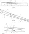
- Figs. 1 - 6 illustrate an exemplary embodiment of the bone plate 1 according to the invention including a lower surface 2, an upper surface 3, a maximum thickness T measured between the lower and upper surfaces 2, 3, a left lateral surface 4, a right lateral surface 5, a longitudinal axis 6 and a plurality of plate holes 7 running from the lower surface 2 to the upper surface 3.
- the bone plate 1 comprises a slot 8 in the lower surface 2 extending from the left lateral surface 4 to the right lateral surface 5.
- the slot 8 has a width W of 0.15 mm measured in a plane parallel to the longitudinal axis 6 and a central plane 16 between the lateral surfaces 4, 5.
- the hollow space defined by the slot 8 extends in the form of a straight cylinder (also called right cylinder) from the left lateral surface 4 to the right lateral surface 5, wherein the slot 8 comprises an undercut feature 9 limiting the opening of the slot 8 when the bone plate 1 is bent longitudinally in a direction aimed at widening the slot 8.
- the undercut feature 9 of the slot 8 has an S-shape in a plane parallel to the longitudinal axis 6 and to the lateral surfaces 4, 5 so that by means of the two bows of the S-shape two complementary projections 13a,13b ( fig. 5 ) are formed.
- the undercut feature 9 of the slot 8 is located in a lower portion of the bone plate1, i.e. in a portion of the bone plate 1 closer to the lower surface 2 of the bone plate 1.
- the S-shape is configured as an "S" being upright in the direction of the longitudinal axis 6 in such a way that one bow of the "S" extends into a vertical section of the slot 8, which extends from the lower surface 2 of the bone plate 1 towards the upper surface 3 of the bone plate 1 and which has a width W measured at the lower surface 2 of the bone plate 1 in a plane parallel to the longitudinal axis 6 and the central plane 16 between the lateral surfaces 4, 5.
- the complementary projections 13a, 13b formed by the S-shaped slot 8 are spaced apart from each other - in case of an unloaded bone plate 1 - by a width of the slot 8 which may be smaller or slightly larger than the width W of the slot 8 measured at the lower surface 2 of the bone plate 1, so that the two projections 13a, 13b engage with each other from the left lateral surface 4 to the right lateral surface 5 when the bone plate 1 is bent in such a way that the tensile forces occur on the lower surface 2 of the bone plate 1 and therewith lock the bone plate 1 against further bending in this direction as well as against torsion around the longitudinal axis 6 of the bone plate 1.
- the slot 8 is configured with the shape of a "T" in an upper portion of the bone plate 1, i.e. in a portion of the bone plate 1 closer to the upper surface 3 of the bone plate 1.
- the free end of the vertical leg of the "T” runs into the S-shaped portion of the slot and the two horizontal legs of the "T” are curved and extend in the direction of the longitudinal axis 6 of the bone plate 1.
- the flexural rigidity (also called bending stiffness) of the bone plate 1 is significantly reduced in the region of the slot 8 so that the bone plate 1 is divided into three longitudinal sections, namely a flexible section 10 in the region of the slot 8 and two rigid sections 11a, 11b whereof each one extends to one lateral end of the bone plate 1.
- the plate holes 7 are located in the rigid sections 11a, 11b so that bone fasteners extending through the plate holes 7 and fixed in bone fragments are arranged in the rigid sections 11a, 11b of the bone plate 1. Therefore, the load acting onto the bone plate 1 due to the weight of the patient or due to forces exerted by the patient is applied to the rigid sections 11a, 11b of the bone plate 1.
- the bone plate 1 is formed as a beam shaped bridging portion 12 which is vertically limited by the top side, i.e. by the horizontal legs of the "T"-shape of the slot 8 and the upper surface 3 of the bone plate 1.
- the bone plate 1 bends first in the flexible section 10. Under a bending load applied in this manner compressive and tensile forces develop in the direction of the longitudinal axis 6 which induce stresses on the bone plate 1. If the effect of the bending moment resulting from applied bending load tends to close the slot 8 the maximum compressive stress is found at the top side of the slot 8 while the maximum tensile stress is found at the upper surface 3.
- the top side 14 of the slot 8 extends along the two horizontal legs of the "T". Because the deflection of the bridging portion 12 depends on a higher degree on the length of the bridging portion 12 than the stress induced on the bridging portion 12 via the bending moment the configuration of the flexible section 10 of the bone plate 1 can be optimized with respect to the desired deflection required for closing the slot 8 at the lower surface 2 of the bone plate 1 and with respect to the maximum stress occurring in the bridging portion 12.
- the height of the bridging portion 12 measured between the top side 14 of the slot 8 and the upper surface 3 of the bone plate 1 varies along the length of the bridging portion 12 from a minimum height in the longitudinal middle plane of the bridging portion 12 to a maximum at the change-over from the bridging portion 12 to the rigid sections 11a, 11b of the bone plate 1.
- the flexural rigidity of the bridging portion 12 at a particular position along the longitudinal axis 6 is dependent on the height of the bridging portion 12 at this position so that the bridging portion 12 can be configured with a varying flexural rigidity where the variation of the flexural rigidity can be specifically adapted to optimize the stress distribution in the bridging portion 12.
- a similar effect - compared to the T-shape of the slot 8 - can be achieved by a configuration of the slot 8 with the shape of an "L" in the upper portion of the bone plate 1, i.e. in a portion of the bone plate 1 closer to the upper surface 3 of the bone plate 1.
- the free end of the vertical leg of the "L” runs into the S-shaped portion of the slot 8 and the horizontal leg of the "L” is straight and extends in the direction of the longitudinal axis 6 of the bone plate 1 ( fig. 7 ).
- the curvature of the neutral axis in the bridging portion 12 is proportional to the bending moment and inversely proportional to the flexural rigidity (bending stiffness), wherein the flexural rigidity is defined as the product E * I, where E is the elastic modulus or also called Young's modulus and I is the second moment of area of the cross-section of the bridging portion 12.
- the deflection of the bridging portion 12 is relevant only, while an eventual bending deformation of the rigid sections 11a, 11b of the bone plate 1 can be neglected.
- the transition from the flexible phase to the rigid phase of the bone plate 1 occurs when the slot 8 closes at the lower surface 2 of the bone plate 1 and therefore depends on the deflection of the bridging portion 12 which is as described above a function of the bending moment, the flexural rigidity of the bridging portion 12 and the length thereof measured in the direction of the longitudinal axis 6 of the bone plate 1.
- the embodiment of the bone plate 1 according to the invention as illustrated in figs. 1 - 6 is configured for an application on metaphyseal fractures, such as the distal femur, the proximal humerus or the distal/proximal tibia.
- One rigid section 11b of the bone plate 1 is spoon-shaped and the slot 8 is arranged closer to the spoon-shaped rigid section 11b.
- the plate holes 7 in the spoon-shaped rigid section 11b are arranged in the enlarged portion which is terminally arranged on the bone plate 1 while the plate holes 7 in the other rigid section 11a are arranged along the longitudinal axis 4 of the bone plate 1 and evenly spaced from each other ( fig. 6 ).
- the bone plate 1 is pre-contoured to a statistically derived shape of the specific anatomical region.
- the bone plate 1 is made from stainless steel. In alternative embodiments the bone plate 1 may be made from titanium or a titanium alloy.
- the bone plate 1 has a plate thickness T which gradually decreases from the region with the slot 8 towards both ends of the plate 1.
- the thickness T in the region of the slot 8 exemplarily, but not limiting, amounts to about 8 mm.
- the bone plate 1 has exemplarily, but not limiting, a width measured at the lower surface 2 at the position of the slot 8 and vertically to the longitudinal axis 6 of about 17 mm.
- the bone plate 1 may have a plate thickness T in the region of the slot 8 of exemplarily, but not limiting, about 12 mm.
- the bone plate 1 has a biphasic stiffness behavior to promote secondary bone healing, i.e. to permit required interfragmentary motion at low functional loading (flexible phase), and to limit this motion to a maximum when the slot closes at higher magnitudes of functional loading (rigid phase).
- the bending stiffness in the flexible section 10 is reduced by 75% compared to a conventional bone plate without a slot when the width W of the slot 8 measured at the lower surface 2 of the bone plate 1 is greater than 0 (flexible phase) and is increased by 75% compared to a conventional bone plate without a slot when the width W of the slot 8 measured at the lower surface 2 of the bone plate 1 is equal to 0 (rigid phase) in off-centric axial compression.
- the plate holes 7 can be configured as variable angle holes. Alternatively, one or more of the plate holes 7 can be configured to receive an angular stable locking screw at a predefined angle.
- the one or more plate holes 7 can be conical or can comprise a conical interior thread.
- the bone plate 1 additionally comprises under-dimensioned threaded screw holes 15 apt to receive fasteners so as to provide means for attachment of a bone healing sensor.
- the plate holes 7 may have different sizes to receive bone screws of different diameters.
- the slot 8 has a width W of about 0.3 mm measured at the lower surface 2 of the bone plate 1 in the direction of the longitudinal axis 6.
- the width W of the slot 8 is chosen so as to allow the bone plate 1 to bend longitudinally - additionally to the intrinsic bendability of a similar unslotted plate - at most to about 10° and to permit a shortening of the length of the lower surface 2 of at most about 1 mm upon complete closure of the slot 8 at the lower surface 2 of the bone plate 1 so that the width W measured at the lower surface 2 is equal to 0.
- a force of about 200 N, acting essentially parallel to the longitudinal axis 6 of the bone plate 1 with an offset of about 20 mm from the lower surface 2 of the bone plate 1 is sufficient to close the slot 8 at the lower surface 2 of the bone plate 1 so that the width W is equal to 0.
- the slot dimensions in the area of the undercut feature 9 are such that lengthening of the lower surface 2 is exemplarily, but not limiting, limited to at most 2 mm when the bone plate 1 is bent longitudinally in a direction aimed at widening the slot 8.
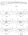
- Figs. 9 - 12 illustrate alternative embodiments of the bone plate 1 according to the invention, which differ from the embodiment of figs. 1 - 6 only in a different configuration of the slot 8 viewed in a plane parallel to the central plane 16 between the lateral surfaces 4, 5.
- fig. 10 illustrates an undercut feature 9 with a Z-shape in a plane parallel to the longitudinal axis 6 and to the central plane 16 between the lateral surfaces 4, 5 instead of an S-shape and fig. 9 illustrates an undercut feature 9 with an ⁇ -shape in a plane parallel to the longitudinal axis 6 and to the central plane 16 between the lateral surfaces 4, 5.
- This ⁇ -shaped undercut feature 9 forms a nose 17 which protrudes from one of the rigid sections 11a ( fig. 3 ) of the bone plate 1 along the longitudinal axis 6 and which has an enlarged free end.
- the adjoining end of the other rigid section 11b ( fig. 3 ) of the bone plate 1 is concavely formed so as to form an encompassment 18 that receives the nose 17 in such a way that movement of the nose 17 relative to the encompassment 18 is limited in both directions along the longitudinal axis 6 of the bone plate 1.
- the slot 8 extends between the nose 17 and the encompassment 18 with the width W measured at the lower surface 2.
- the encompassment 18 encloses the nose 17 more than 180° in a view orthogonal to the central plane 16 between the lateral surfaces 4, 5 so that bending of the bridging portion 12 is limited in both directions, i.e. in a first direction where the maximum tensile forces occur on the upper surface 3 and in a second direction where the maximum compressive forces occur on the upper surface 3 so as to provide resistance against tensile forces and valgus bending. Due to the S-shape, Z-shape or ⁇ -shape of the undercut feature two adjoining projections are formed which additionally provide resistance against torsion of the bone plate.
- Fig. 11 illustrates a slot 8 which is similarly configured as the slot 8 of figs.
- the width of the slot 8 may significantly widen towards the upper surface 3 of the bone plate 1 e.g. in a T-shape to form a stress distribution feature.
- the width W of the slot 8 measured in a plane parallel to the longitudinal axis 6 and to the central plane 16 between the lateral surfaces 4, 5 is significantly enlarged along the horizontal legs of the T-shaped slot 8.
- the flexible section 10 of the bone plate 1 comprises a compartment 19 extending from the top side 14 of the slot 8.
- the compartment 19 is open via the slot 8 at the lower surface 2 of the bone plate 1.
- the compartment 19 is suitable to accommodate one or more sensors (not shown), preferably for measuring strain, displacement, load or pressure or temperature.
- the compartment 19 is suitable to accommodate one or more actuators, to alter the implant's mechanical properties, or store drugs for controlled release or to provide space for callus growth.
- the slot 8 is fully or partially covered by an elastic biocompatible membrane, wherein the membrane is impermeable for micro and nano metallic wear particles so that potential wear particles generated through intermittent slot closing contact can be confined in the membrane.
- the slot 8 may be filled with a softer material to reduce the "dead space" and to bind wear particles.
- the slot 8 is formed using a wire-erosion or waterjet cutting process to generated the slot 8 by penetrating the bone plate 1 with an eroding or waterjet cutting instrument into one of the lateral surfaces 4, 5 and guiding it in a directed straight manner to the opposite lateral surface thereby creating a through going slot 8.
Landscapes
- Health & Medical Sciences (AREA)
- Orthopedic Medicine & Surgery (AREA)
- Surgery (AREA)
- Life Sciences & Earth Sciences (AREA)
- Heart & Thoracic Surgery (AREA)
- Animal Behavior & Ethology (AREA)
- Engineering & Computer Science (AREA)
- Biomedical Technology (AREA)
- Neurology (AREA)
- Medical Informatics (AREA)
- Molecular Biology (AREA)
- Nuclear Medicine, Radiotherapy & Molecular Imaging (AREA)
- General Health & Medical Sciences (AREA)
- Public Health (AREA)
- Veterinary Medicine (AREA)
- Surgical Instruments (AREA)
- Fishing Rods (AREA)
- Prostheses (AREA)
Description
- The invention relates to a bone plate according to the preamble of
claim 1. Bone plates which exhibit a biphasic stiffness behavior promote secondary bone healing. These bone plates permit required interfragmentary motion at low functional loading (flexible phase), and limit said motion to a maximum when the slot closes at higher magnitudes of functional loading (rigid phase). These bone plates, hence, provide controlled motion to the bone fracture largely independent from the magnitude of functional loading. Thereby (i) healing complications caused by mechanically adverse conditions can be avoided and (ii) the average time to bony union may be shortened. - It was found that interfragmentary motion of 0.5 mm (0.2 - 1 mm) provides a good healing outcome in different fracture sizes (1, 2 and 6 mm cover the vast majority of fractures). Known bone plates with an optimized slot width avoid overstimulation of the fracture, which could lead to healing complications such as hypertrophic delayed- and non-unions.
- A biphasic bone plate is known form
WO 2017/024416 . In order to provide resistance against tensile forces and valgus bending of the bone plate this known bone plate comprises a slot having a lower section which extends from the lower surface of the bone plate towards the upper surface and which extends across the bone plate along the form of an "Ω" in a view onto the lower surface of the bone plate. This Ω-shape is formed by a nose which protrudes from one of the rigid sections of the bone plate along the longitudinal axis of the bone plate and which has an enlarged free end and by an concavely formed adjoining end of the other rigid section, wherein the concavity forms an encompassment for the nose so that movement of the nose relative to the encompassment is limited in both directions along the longitudinal axis of the bone plate. Further, a central section of the slot has a width increasing towards the upper section of the slot and the upper section of the slot has two curved legs extending in the direction of the longitudinal axis of the bone plate. The lower section of the slot has an essentially cylindrical shape which has an Ω-shaped base on the lower surface of the bone plate and which has a peripheral surface extending vertically, i.e. orthogonally to the lower surface of the bone plate. Contrarily, the central section and the upper section of the slot each have an essentially cylindrical shape having their bases on the lateral sides of the bone plate while their peripheral surfaces extend laterally, i.e. parallel to a transverse axis of the bone plate which extends orthogonally to the longitudinal axis between the two lateral surfaces of the bone plate. Due to the fact that the central axes of the cylinders of the central and upper sections of the slot extend orthogonally to the central axis of the cylinder of the lower section of the slot, the lower section and the central and upper sections have to be manufactured in separate and subsequent working processes resulting in a complex and costly manufacture of the slot. - The window size of the plate according to
WO 2017/024416 is solely determined by the width W of the slot feature at the lower surface of the plate. It is hence intuitive to limit not only the closing but also the opening of the slot by an undercut feature located at the lower plate surface (as disclosed in the previous invention). - It is the object of the invention to provide a bi-phasic bone plate which permits a production of the bone plate in a single manufacturing step without reducing the resistance of the bi-phasic bone plate against tensile forces and valgus bending and the possibility of manufacturing small slot width (of less than 0.3mm) without the necessity of assembling different plate parts.
- The invention solves the posed problem with a bone plate comprising the features of
claim 1. - A method of manufacturing the bone plate is also described herein to aid understanding the invention. This method does not form part of the claimed invention.
- The advantages of the bone plate according to the invention can be essentially seen therein that:
- a straight slot can be produced in a single manufacturing step from a single work piece using a standard wire-erosion or waterjet cutting process. Production time, complexity and, hence, production costs are thereby reduced; and
- catastrophic failure of the bone plate under unphysiological loading conditions (valgus bending) can be prevented.
- Furthermore the inventive idea to shift the undercut feature (opening limiter) away from the lower plate surface to a different location and orientation produces the additional unexpected advantages of:
- Producibility of the slot incl. undercut feature in a single manufacturing step with a well-established and robust manufacturing process, such as wire-erosion.
- Producibility of the slot incl. undercut feature with a desired slot width of <0.3mm. Other manufacturing processes, e.g. sink erosion are not capable of generation such narrow slots. The alternative, assembly from different parts, can be avoided.
- The contact area at the lower plate surface at slot closing becomes a flat surface over the entire width of the bone plate, which allows for uniform and distributed contact, limiting particle wear generation. A non-straight but curved slot (e.g. omega) does not allow uniform slot closing due to the non-constant bent-line of the bone plate.
- The bone plate according to the invention exhibits a significant increase in strength [>2x ultimate load to failure (off-centric axial compression)] and fatigue performance (>4x cycles to failure) as compared to a standard bone plate. This reduces the risk for clinical implant failure significantly.
- Further advantageous embodiments of the invention are set forth in the dependent claims.
- In a special embodiment the width W of the slot measured in a plane parallel to the longitudinal axis and to the central plane between the lateral surfaces is variable. This configuration permits the advantage that the slot width may significantly widen towards the upper surface e.g. in a T-shape to form a stress distribution feature.
- In another embodiment the undercut feature has an S-shape, a Z-shape or an Ω-shape in a plane parallel to the longitudinal axis and to the central plane between the lateral surfaces. Due to the S-shape, Z-shape or Ω-shape of the undercut feature two adjoining projections are formed which additionally provide resistance against torsion of the bone plate.
- In a further embodiment the dimensions of the undercut feature are chosen such that lengthening of the lower surface is limited to at most 3 mm, preferably at most 1 mm when the bone plate is bent longitudinally in a direction aimed at widening the slot.
- In a further embodiment the slot has a width W in the range of 0.1 to 1.3 mm, preferably in the range of 0.15 - 0.30 mm measured at the lower surface of the bone plate in the direction of the longitudinal axis.
- In a further embodiment the slot is configured with the shape of a "T" or of an "L" in an upper portion of the bone plate, wherein the free end of the vertical leg of the "T" or "L" runs into the undercut feature of the slot and the two horizontal legs of the "T" or the horizontal leg of the "L" extend in the direction of the longitudinal axis of the bone plate and are preferably curved.
- In yet a further embodiment the walls of the slot at the lower surface of the bone plate are angulated with respect to each other such that they become parallel upon closing of the slot. The slot deforms through bending of the bone plate which leads to tilting of the originally parallel walls and hence leads to a line contact of the slot at closure. This again may generate accentuated metal wear at the contact area. Creating an angulated slot for compensating the tilt increases the contact area and hence reduces wear.
- In another embodiment the dimensions of the slot are chosen such that the length of the lower surface is shortened at most 1 mm, preferably at most 0.3 mm upon complete closure of the slot at the lower surface of the bone plate so that the width W measured at the lower surface is equal to 0.
- In another embodiment the slot allows the plate to bend longitudinally at least to the amount of 1.0°, preferably at least 1.5°.
- In a further embodiment the bone plate comprises more than one slot.
- In another embodiment the bone plate additionally comprises means for attachment of a bone healing sensor, preferably in the in the form of threaded screw holes apt to receive fasteners.
- In another embodiment the bone plate is configured in such a way that the bending stiffness in the flexible section is reduced by 75% compared to a conventional bone plate without a slot when the width W of the slot measured at the lower surface of the bone plate is greater than 0 and is increased by 75% compared to a conventional bone plate without a slot when the width W of the slot measured at the lower surface of the bone plate is equal to 0 under off-centric axial compression. The aforementioned increase of the bending stiffness of about 75% compared to a conventional bone plate without a slot highly depends on the loading mode and can be significantly higher.
- In another embodiment the dimensions of the slot are chosen such that the bone plate is allowed to bend longitudinally - additionally to the intrinsic bendability of the unslotted plate - at most to the amount of 20°, preferably at most to the amount of 10°
- In another embodiment the width W of the slot measured at the lower surface of the bone plate in the direction of the longitudinal axis is larger than 0.25 mm, preferably larger than 0.20 mm.
- In again another embodiment the width W of the slot measured at the lower surface of the bone plate in the direction of the longitudinal axis is smaller than 0.30 mm, preferably smaller than 0.25 mm.
- In a further embodiment the bone plate has a maximum thickness in the range of 6 mm - 13 mm.
- In a further embodiment the bone plate has a thickness in the range of 10 mm - 12 mm, preferably for use on the femur.
- In a further embodiment the bone plate has a thickness in the range of 4 mm - 9 mm preferably for use on the humerus or tibia.
- In another embodiment the bone plate has a width measured at the lower surface at the position of the slot and vertically to the longitudinal axis in the range of 14 mm - 22 mm, preferably in the range of 17 mm to 21 mm.
- In another embodiment a force in the range of 50 - 400 N, preferably in the range of 100 - 300 N, acting essentially parallel to the longitudinal axis of the bone plate with an offset of 10 mm to 30 mm from the lower surface of the bone plate is sufficient to close the slot at the lower surface of the bone plate so that the width W is equal to 0.
- In a further embodiment the slot has a curved-shaped form seen in a longitudinal cross-section of the bone plate, the curved-shaped form enlarging from the lower surface towards the upper surface.
- Preferably, the plate thickness T gradually decreases from the slot towards both ends of the bone plate.
- In a further embodiment at least one of the plurality of plate holes is configured to receive an angular stable locking screw at a predefined angle.
- In a further embodiment at least one of the plurality of plate holes is configured to receive a variable angle locking screw.
- In another embodiment the plate holes have different sizes to receive bone screws of different diameters.
- Preferably, the bone plate is made of titanium or a titanium alloy and preferably from stainless steel.
- Preferably, the bone plate is used for the treatment of bone fractures.
- In a further embodiment the slot is fully or partially covered by an elastic biocompatible membrane, the membrane preferably being impermeable for micro and nano metallic wear particles. By this means the advantage can be achieved that potential wear particles generated through intermittent slot closing contact can be confined in the membrane.
- In a further embodiment the bone plate is pre-contoured to a statistically derived shape of a specific anatomical region.
- A method of manufacturing the bone plate according to the invention is also described (but not claimed), wherein the slot is formed using a wire-erosion or waterjet cutting process.
- Preferably, the slot is generated by penetrating the bone plate with an eroding or cutting instrument into one of the lateral surfaces and guiding it in a directed straight manner to the opposite lateral surface thereby creating a through going slot.
- A special embodiment of the invention will be described in the following by way of example and with reference to the accompanying drawings in which:
-
Fig. 1 illustrates a perspective view of an embodiment of the bone plate according to the invention; -
Fig. 2 illustrates a magnified view of detail A infig. 1 ; -
Fig. 3 illustrates a lateral view of the embodiment offig. 1 ; -
Fig. 4 illustrates a perspective view of a central portion of the embodiment offig. 1 ; -
Fig. 5 illustrates a lateral view of a central portion of the embodiment offig. 1 ; -
Fig. 6 illustrates a bottom view of the embodiment offig. 1 ; -
Fig. 7 illustrates a lateral view of a central portion of another embodiment of the bone plate according to the invention; -
Fig. 8 illustrates a lateral view of a central portion of again another embodiment of the bone plate according to the invention; -
Fig. 9 illustrates a lateral view of a central portion of a further embodiment of the bone plate according to the invention; -
Fig. 10 illustrates a lateral view of a central portion of a further embodiment of the bone plate according to the invention; -
Fig. 11 illustrates a lateral view of a central portion of a further embodiment of the bone plate according to the invention; and -
Fig. 12 illustrates a lateral view of a central portion of a further embodiment of the bone plate according to the invention. -
Figs. 1 - 6 illustrate an exemplary embodiment of thebone plate 1 according to the invention including alower surface 2, anupper surface 3, a maximum thickness T measured between the lower andupper surfaces lateral surface 4, a rightlateral surface 5, alongitudinal axis 6 and a plurality ofplate holes 7 running from thelower surface 2 to theupper surface 3. Furthermore, thebone plate 1 comprises aslot 8 in thelower surface 2 extending from the leftlateral surface 4 to the rightlateral surface 5. Theslot 8 has a width W of 0.15 mm measured in a plane parallel to thelongitudinal axis 6 and acentral plane 16 between thelateral surfaces - The hollow space defined by the
slot 8 extends in the form of a straight cylinder (also called right cylinder) from the leftlateral surface 4 to the rightlateral surface 5, wherein theslot 8 comprises anundercut feature 9 limiting the opening of theslot 8 when thebone plate 1 is bent longitudinally in a direction aimed at widening theslot 8. - Exemplarily, but not limiting, the
undercut feature 9 of theslot 8 has an S-shape in a plane parallel to thelongitudinal axis 6 and to the lateral surfaces 4, 5 so that by means of the two bows of the S-shape twocomplementary projections fig. 5 ) are formed. Theundercut feature 9 of theslot 8 is located in a lower portion of the bone plate1, i.e. in a portion of thebone plate 1 closer to thelower surface 2 of thebone plate 1. - The S-shape is configured as an "S" being upright in the direction of the
longitudinal axis 6 in such a way that one bow of the "S" extends into a vertical section of theslot 8, which extends from thelower surface 2 of thebone plate 1 towards theupper surface 3 of thebone plate 1 and which has a width W measured at thelower surface 2 of thebone plate 1 in a plane parallel to thelongitudinal axis 6 and thecentral plane 16 between thelateral surfaces - The
complementary projections slot 8 are spaced apart from each other - in case of an unloaded bone plate 1 - by a width of theslot 8 which may be smaller or slightly larger than the width W of theslot 8 measured at thelower surface 2 of thebone plate 1, so that the twoprojections lateral surface 4 to the rightlateral surface 5 when thebone plate 1 is bent in such a way that the tensile forces occur on thelower surface 2 of thebone plate 1 and therewith lock thebone plate 1 against further bending in this direction as well as against torsion around thelongitudinal axis 6 of thebone plate 1. - In the embodiment illustrated in
figs. 1 - 6 theslot 8 is configured with the shape of a "T" in an upper portion of thebone plate 1, i.e. in a portion of thebone plate 1 closer to theupper surface 3 of thebone plate 1. Thereby, the free end of the vertical leg of the "T" runs into the S-shaped portion of the slot and the two horizontal legs of the "T" are curved and extend in the direction of thelongitudinal axis 6 of thebone plate 1. - Due to the
slot 8 the flexural rigidity (also called bending stiffness) of thebone plate 1 is significantly reduced in the region of theslot 8 so that thebone plate 1 is divided into three longitudinal sections, namely aflexible section 10 in the region of theslot 8 and tworigid sections bone plate 1. The plate holes 7 are located in therigid sections rigid sections bone plate 1. Therefore, the load acting onto thebone plate 1 due to the weight of the patient or due to forces exerted by the patient is applied to therigid sections bone plate 1. In theflexible section 10 thebone plate 1 is formed as a beam shaped bridgingportion 12 which is vertically limited by the top side, i.e. by the horizontal legs of the "T"-shape of theslot 8 and theupper surface 3 of thebone plate 1. - Due to the reduced flexural rigidity of the bridging
portion 12 compared to therigid sections bone plate 1 thebone plate 1 bends first in theflexible section 10. Under a bending load applied in this manner compressive and tensile forces develop in the direction of thelongitudinal axis 6 which induce stresses on thebone plate 1. If the effect of the bending moment resulting from applied bending load tends to close theslot 8 the maximum compressive stress is found at the top side of theslot 8 while the maximum tensile stress is found at theupper surface 3. - The
top side 14 of theslot 8 extends along the two horizontal legs of the "T". Because the deflection of the bridgingportion 12 depends on a higher degree on the length of the bridgingportion 12 than the stress induced on the bridgingportion 12 via the bending moment the configuration of theflexible section 10 of thebone plate 1 can be optimized with respect to the desired deflection required for closing theslot 8 at thelower surface 2 of thebone plate 1 and with respect to the maximum stress occurring in the bridgingportion 12. Furthermore, due the curved configuration of the two horizontal legs of the "T" the height of the bridgingportion 12 measured between thetop side 14 of theslot 8 and theupper surface 3 of thebone plate 1 varies along the length of the bridgingportion 12 from a minimum height in the longitudinal middle plane of the bridgingportion 12 to a maximum at the change-over from the bridgingportion 12 to therigid sections bone plate 1. The flexural rigidity of the bridgingportion 12 at a particular position along thelongitudinal axis 6 is dependent on the height of the bridgingportion 12 at this position so that the bridgingportion 12 can be configured with a varying flexural rigidity where the variation of the flexural rigidity can be specifically adapted to optimize the stress distribution in the bridgingportion 12. - Alternatively, a similar effect - compared to the T-shape of the slot 8 - can be achieved by a configuration of the
slot 8 with the shape of an "L" in the upper portion of thebone plate 1, i.e. in a portion of thebone plate 1 closer to theupper surface 3 of thebone plate 1. Thereby, the free end of the vertical leg of the "L" runs into the S-shaped portion of theslot 8 and the horizontal leg of the "L" is straight and extends in the direction of thelongitudinal axis 6 of the bone plate 1 (fig. 7 ). - According to the Euler-Bernoulli bending theory the curvature of the neutral axis in the bridging
portion 12 is proportional to the bending moment and inversely proportional to the flexural rigidity (bending stiffness), wherein the flexural rigidity is defined as the product E * I, where E is the elastic modulus or also called Young's modulus and I is the second moment of area of the cross-section of the bridgingportion 12. - For the narrowing and the closure of the
slot 8 the deflection of the bridgingportion 12 is relevant only, while an eventual bending deformation of therigid sections bone plate 1 can be neglected. - The transition from the flexible phase to the rigid phase of the
bone plate 1 occurs when theslot 8 closes at thelower surface 2 of thebone plate 1 and therefore depends on the deflection of the bridgingportion 12 which is as described above a function of the bending moment, the flexural rigidity of the bridgingportion 12 and the length thereof measured in the direction of thelongitudinal axis 6 of thebone plate 1. - Exemplarily, but not limiting, the embodiment of the
bone plate 1 according to the invention as illustrated infigs. 1 - 6 is configured for an application on metaphyseal fractures, such as the distal femur, the proximal humerus or the distal/proximal tibia. Onerigid section 11b of thebone plate 1 is spoon-shaped and theslot 8 is arranged closer to the spoon-shapedrigid section 11b. Further, the plate holes 7 in the spoon-shapedrigid section 11b are arranged in the enlarged portion which is terminally arranged on thebone plate 1 while the plate holes 7 in the otherrigid section 11a are arranged along thelongitudinal axis 4 of thebone plate 1 and evenly spaced from each other (fig. 6 ). By these means thebone plate 1 is pre-contoured to a statistically derived shape of the specific anatomical region. - Exemplarily, but not limiting the
bone plate 1 is made from stainless steel. In alternative embodiments thebone plate 1 may be made from titanium or a titanium alloy. Thebone plate 1 has a plate thickness T which gradually decreases from the region with theslot 8 towards both ends of theplate 1. For the specific application of thebone plate 1 on the humerus or tibia the thickness T in the region of theslot 8 exemplarily, but not limiting, amounts to about 8 mm. Further, thebone plate 1 has exemplarily, but not limiting, a width measured at thelower surface 2 at the position of theslot 8 and vertically to thelongitudinal axis 6 of about 17 mm. Alternatively, for use on the femur thebone plate 1 may have a plate thickness T in the region of theslot 8 of exemplarily, but not limiting, about 12 mm. - The
bone plate 1 has a biphasic stiffness behavior to promote secondary bone healing, i.e. to permit required interfragmentary motion at low functional loading (flexible phase), and to limit this motion to a maximum when the slot closes at higher magnitudes of functional loading (rigid phase). The bending stiffness in theflexible section 10 is reduced by 75% compared to a conventional bone plate without a slot when the width W of theslot 8 measured at thelower surface 2 of thebone plate 1 is greater than 0 (flexible phase) and is increased by 75% compared to a conventional bone plate without a slot when the width W of theslot 8 measured at thelower surface 2 of thebone plate 1 is equal to 0 (rigid phase) in off-centric axial compression. - The plate holes 7 can be configured as variable angle holes. Alternatively, one or more of the plate holes 7 can be configured to receive an angular stable locking screw at a predefined angle. For this purpose the one or
more plate holes 7 can be conical or can comprise a conical interior thread. Thebone plate 1 additionally comprises under-dimensioned threaded screw holes 15 apt to receive fasteners so as to provide means for attachment of a bone healing sensor. In other alternative embodiments the plate holes 7 may have different sizes to receive bone screws of different diameters. - Exemplarily, but not limiting, the
slot 8 has a width W of about 0.3 mm measured at thelower surface 2 of thebone plate 1 in the direction of thelongitudinal axis 6. The width W of theslot 8 is chosen so as to allow thebone plate 1 to bend longitudinally - additionally to the intrinsic bendability of a similar unslotted plate - at most to about 10° and to permit a shortening of the length of thelower surface 2 of at most about 1 mm upon complete closure of theslot 8 at thelower surface 2 of thebone plate 1 so that the width W measured at thelower surface 2 is equal to 0. Thereby, a force of about 200 N, acting essentially parallel to thelongitudinal axis 6 of thebone plate 1 with an offset of about 20 mm from thelower surface 2 of thebone plate 1 is sufficient to close theslot 8 at thelower surface 2 of thebone plate 1 so that the width W is equal to 0. The slot dimensions in the area of the undercutfeature 9 are such that lengthening of thelower surface 2 is exemplarily, but not limiting, limited to at most 2 mm when thebone plate 1 is bent longitudinally in a direction aimed at widening theslot 8. -
Figs. 9 - 12 illustrate alternative embodiments of thebone plate 1 according to the invention, which differ from the embodiment offigs. 1 - 6 only in a different configuration of theslot 8 viewed in a plane parallel to thecentral plane 16 between thelateral surfaces - Thereby,
fig. 10 illustrates anundercut feature 9 with a Z-shape in a plane parallel to thelongitudinal axis 6 and to thecentral plane 16 between thelateral surfaces fig. 9 illustrates anundercut feature 9 with an Ω-shape in a plane parallel to thelongitudinal axis 6 and to thecentral plane 16 between thelateral surfaces - This Ω-shaped
undercut feature 9 forms anose 17 which protrudes from one of therigid sections 11a (fig. 3 ) of thebone plate 1 along thelongitudinal axis 6 and which has an enlarged free end. The adjoining end of the otherrigid section 11b (fig. 3 ) of thebone plate 1 is concavely formed so as to form anencompassment 18 that receives thenose 17 in such a way that movement of thenose 17 relative to theencompassment 18 is limited in both directions along thelongitudinal axis 6 of thebone plate 1. In the undeformed state of thebone plate 1 theslot 8 extends between thenose 17 and theencompassment 18 with the width W measured at thelower surface 2. Theencompassment 18 encloses thenose 17 more than 180° in a view orthogonal to thecentral plane 16 between thelateral surfaces portion 12 is limited in both directions, i.e. in a first direction where the maximum tensile forces occur on theupper surface 3 and in a second direction where the maximum compressive forces occur on theupper surface 3 so as to provide resistance against tensile forces and valgus bending. Due to the S-shape, Z-shape or Ω-shape of the undercut feature two adjoining projections are formed which additionally provide resistance against torsion of the bone plate.Fig. 11 illustrates aslot 8 which is similarly configured as theslot 8 offigs. 1 - 6 with the shape of a "T" in an upper portion of thebone plate 1, i.e. in a portion of thebone plate 1 closer to theupper surface 3 of thebone plate 1 but the free end of the vertical leg of the "T" runs into the S-shaped portion of theslot 8 in such a way that the vertical section of theslot 8 into which one bow of the "S" runs and which extends from thelower surface 2 of thebone plate 1 towards theupper surface 3 is located centrally between the two horizontal legs of the "T". A further alternative embodiment is illustrated infig. 12 which differs from the embodiment offig. 11 only therein that the walls of theslot 8 at thelower surface 2 of thebone plate 1 are angulated with respect to each other by an angle α such that they become parallel upon closing of theslot 8. By this means the contact area between the walls of theslot 8 is increased upon closure of theslot 8 when a load is applied to thebone plate 1 so that metal wear at the contact area is reduced. - As mentioned above, the width of the
slot 8 may significantly widen towards theupper surface 3 of thebone plate 1 e.g. in a T-shape to form a stress distribution feature. In an alternative embodiment of thebone plate 1 illustrated infig. 8 the width W of theslot 8 measured in a plane parallel to thelongitudinal axis 6 and to thecentral plane 16 between thelateral surfaces slot 8. By this means theflexible section 10 of thebone plate 1 comprises acompartment 19 extending from thetop side 14 of theslot 8. Thecompartment 19 is open via theslot 8 at thelower surface 2 of thebone plate 1. Thecompartment 19 is suitable to accommodate one or more sensors (not shown), preferably for measuring strain, displacement, load or pressure or temperature. Alternatively or additionally thecompartment 19 is suitable to accommodate one or more actuators, to alter the implant's mechanical properties, or store drugs for controlled release or to provide space for callus growth. - In further alternative embodiments the
slot 8 is fully or partially covered by an elastic biocompatible membrane, wherein the membrane is impermeable for micro and nano metallic wear particles so that potential wear particles generated through intermittent slot closing contact can be confined in the membrane. Alternatively, theslot 8 may be filled with a softer material to reduce the "dead space" and to bind wear particles. According to the method of manufacturing thebone plate 1 according to the invention theslot 8 is formed using a wire-erosion or waterjet cutting process to generated theslot 8 by penetrating thebone plate 1 with an eroding or waterjet cutting instrument into one of thelateral surfaces slot 8.
Claims (9)
- Bone plate (1) with a lower surface (2), an upper surface (3), a maximum thickness T measured between the lower and upper surfaces (2, 3), a left lateral surface (4), a right lateral surface (5),a longitudinal axis (6) and a plurality of plate holes (7) running from the lower surface (2) to the upper surface (3), the bone plate (1) further having a slot (8) in the lower surface (2) extending from the left lateral surface (4) to the right lateral surface (5) and having a width W measured in a plane parallel to the longitudinal axis (6) and a central plane (16) between the lateral surfaces (4, 5), characterized in that(i) the hollow space defined by the slot (8) extends in the form of a straight cylinder from the left lateral surface (4) to the right lateral surface (5);(ii) the slot (8) comprises an undercut feature (9) limiting the opening of the slot (8) when the bone plate (1) is bent longitudinally in a direction aimed at widening the slot (8).
- Bone plate (1) according to claim 1, characterized in that the width W of the slot (8) measured in a plane parallel to the longitudinal axis (6) and to the central plane (16) between the lateral surfaces (4, 5) is variable.
- Bone plate (1) according to claim 1 or 2, characterized in that the undercut feature (9) has an S-shape, a Z-shape or an Ω-shape in a plane parallel to the longitudinal axis (6) and to the central plane (16) between the lateral surfaces (4, 5).
- Bone plate (1) according to one of the clams 1 to 3, characterized in that the dimensions of the undercut feature (9) are chosen such that lengthening of the lower surface (2) is limited to at most 3 mm, preferably at most 1 mm when the bone plate (1) is bent longitudinally in a direction aimed at widening the slot (8).
- Bone plate (1) according to one of the claims 1 to 4, characterized in that the slot (8) has a width W in the range of 0.1 to 1.3 mm, preferably in the range of 0.15 - 0.30 mm measured at the lower surface (2) of the bone plate (1) in the direction of the longitudinal axis (6).
- Bone plate (1) according to one of the claims 1 to 5, characterized in that the slot (8) is configured with the shape of a "T" or of an "L" in an upper portion of the bone plate 1, wherein the free end of the vertical leg of the "T" or "L" runs into the undercut feature (9) of the slot (8) and the two horizontal legs of the "T" or the horizontal leg of the "L" extend in the direction of the longitudinal axis (6) of the bone plate (1) and are preferably curved.
- Bone plate (1) according to one of the claims 1 to 6, characterized in that the walls of the slot (8) at the lower surface (2) of the bone plate (1) are angulated with respect to each other such that they become parallel upon closing of the slot (8).
- Bone plate (1) according to one of the clams 1 to 7, characterized in that the dimensions of the slot (9) are chosen such that the length of the lower surface (2) is shortened at most 1 mm, preferably at most 0.3 mm upon complete closure of the slot (6) at the lower surface (2) of the bone plate (1) so that the width W measured at the lower surface (2) is equal to 0.
- Bone plate (1) according to one of the claims 1 to 8, characterized in that the slot (8) allows the plate (1) to bend longitudinally at least to the amount of 1.0°, preferably at least 1.5°.
Applications Claiming Priority (2)
| Application Number | Priority Date | Filing Date | Title |
|---|---|---|---|
| CH15152019 | 2019-11-29 | ||
| PCT/CH2020/050012 WO2021102591A1 (en) | 2019-11-29 | 2020-11-24 | Biphasic bone plate |
Publications (3)
| Publication Number | Publication Date |
|---|---|
| EP4065017A1 EP4065017A1 (en) | 2022-10-05 |
| EP4065017C0 EP4065017C0 (en) | 2024-10-16 |
| EP4065017B1 true EP4065017B1 (en) | 2024-10-16 |
Family
ID=73646026
Family Applications (1)
| Application Number | Title | Priority Date | Filing Date |
|---|---|---|---|
| EP20816379.0A Active EP4065017B1 (en) | 2019-11-29 | 2020-11-24 | Biphasic bone plate |
Country Status (6)
| Country | Link |
|---|---|
| US (1) | US12324613B2 (en) |
| EP (1) | EP4065017B1 (en) |
| JP (1) | JP7682882B2 (en) |
| AU (1) | AU2020390870B2 (en) |
| CA (1) | CA3158901A1 (en) |
| WO (1) | WO2021102591A1 (en) |
Families Citing this family (1)
| Publication number | Priority date | Publication date | Assignee | Title |
|---|---|---|---|---|
| DE202021003115U1 (en) | 2021-10-05 | 2023-01-09 | Mosler Lüder | fracture implant |
Family Cites Families (6)
| Publication number | Priority date | Publication date | Assignee | Title |
|---|---|---|---|---|
| FR2819169A1 (en) | 2001-01-09 | 2002-07-12 | Brice Edouard | OSTEOSYNTHESIS DEVICE FOR SPINE |
| US8029551B2 (en) * | 2006-01-10 | 2011-10-04 | Running Donald E | Fracture fixation plate with cover sheath |
| US8979901B2 (en) * | 2010-08-26 | 2015-03-17 | Warsaw Orthopedic, Inc. | Dynamic bone fastener with a preset range of motion |
| EP2832309B1 (en) * | 2013-07-31 | 2018-03-07 | Biedermann Technologies GmbH & Co. KG | Implant for bones or vertebrae with self-constrained flexibility |
| JP6791946B2 (en) * | 2015-08-07 | 2020-11-25 | アーオー テクノロジー アクチエンゲゼルシャフト | Bone plate |
| US11224467B2 (en) * | 2016-02-26 | 2022-01-18 | Activortho, Inc. | Active compression apparatus, methods of assembly and methods of use |
-
2020
- 2020-11-24 AU AU2020390870A patent/AU2020390870B2/en active Active
- 2020-11-24 EP EP20816379.0A patent/EP4065017B1/en active Active
- 2020-11-24 US US17/780,576 patent/US12324613B2/en active Active
- 2020-11-24 JP JP2022531494A patent/JP7682882B2/en active Active
- 2020-11-24 CA CA3158901A patent/CA3158901A1/en active Pending
- 2020-11-24 WO PCT/CH2020/050012 patent/WO2021102591A1/en not_active Ceased
Also Published As
| Publication number | Publication date |
|---|---|
| EP4065017C0 (en) | 2024-10-16 |
| WO2021102591A1 (en) | 2021-06-03 |
| AU2020390870B2 (en) | 2025-12-18 |
| JP2023504098A (en) | 2023-02-01 |
| US12324613B2 (en) | 2025-06-10 |
| JP7682882B2 (en) | 2025-05-26 |
| AU2020390870A1 (en) | 2022-06-09 |
| CA3158901A1 (en) | 2021-06-03 |
| US20230000534A1 (en) | 2023-01-05 |
| EP4065017A1 (en) | 2022-10-05 |
Similar Documents
| Publication | Publication Date | Title |
|---|---|---|
| US11116499B1 (en) | Low profile staple and methods for using the same | |
| US7846189B2 (en) | Orthopaedic bone plate | |
| US10932831B2 (en) | Bone plate and bone plate system | |
| US8097022B2 (en) | Flexible coupling members for spinal stabilization members | |
| US10085775B2 (en) | Implant for bones or vertebrae with self-constrained flexibility | |
| US20090062868A1 (en) | Pedicle screw | |
| US20060276787A1 (en) | Pedicle screw, cervical screw and rod | |
| US20160278814A1 (en) | Semi-constrained anchoring system | |
| EP1694229B1 (en) | Device for osteosynthesis of the spine | |
| EP0359816A1 (en) | Dual-taper, asymmetric hole placement in reconstruction and fracture plates | |
| JP4714733B2 (en) | Bonding rod for bone bonding element | |
| AU2019200888A1 (en) | Semi-constrained anchoring system for correcting a spinal deformity | |
| US10695113B2 (en) | Bone plate | |
| AU2020390870B2 (en) | Biphasic bone plate | |
| AU2004320254B2 (en) | Osteosynthesis plate | |
| CN101516283A (en) | Element of a vertebral column stabilization device | |
| US7935115B2 (en) | System for fixation of fractures comprising an elastic chassis | |
| AU2002363205A1 (en) | A system for fixation of fractures comprising an elastic chassis | |
| JP2024535552A (en) | Plate implant | |
| EP3600098B1 (en) | Bone plate | |
| WO2023212615A2 (en) | Implantable screw and methods for use |
Legal Events
| Date | Code | Title | Description |
|---|---|---|---|
| STAA | Information on the status of an ep patent application or granted ep patent |
Free format text: STATUS: UNKNOWN |
|
| STAA | Information on the status of an ep patent application or granted ep patent |
Free format text: STATUS: THE INTERNATIONAL PUBLICATION HAS BEEN MADE |
|
| PUAI | Public reference made under article 153(3) epc to a published international application that has entered the european phase |
Free format text: ORIGINAL CODE: 0009012 |
|
| STAA | Information on the status of an ep patent application or granted ep patent |
Free format text: STATUS: REQUEST FOR EXAMINATION WAS MADE |
|
| 17P | Request for examination filed |
Effective date: 20220519 |
|
| AK | Designated contracting states |
Kind code of ref document: A1 Designated state(s): AL AT BE BG CH CY CZ DE DK EE ES FI FR GB GR HR HU IE IS IT LI LT LU LV MC MK MT NL NO PL PT RO RS SE SI SK SM TR |
|
| DAV | Request for validation of the european patent (deleted) | ||
| DAX | Request for extension of the european patent (deleted) | ||
| GRAP | Despatch of communication of intention to grant a patent |
Free format text: ORIGINAL CODE: EPIDOSNIGR1 |
|
| STAA | Information on the status of an ep patent application or granted ep patent |
Free format text: STATUS: GRANT OF PATENT IS INTENDED |
|
| INTG | Intention to grant announced |
Effective date: 20240527 |
|
| GRAS | Grant fee paid |
Free format text: ORIGINAL CODE: EPIDOSNIGR3 |
|
| GRAA | (expected) grant |
Free format text: ORIGINAL CODE: 0009210 |
|
| STAA | Information on the status of an ep patent application or granted ep patent |
Free format text: STATUS: THE PATENT HAS BEEN GRANTED |
|
| AK | Designated contracting states |
Kind code of ref document: B1 Designated state(s): AL AT BE BG CH CY CZ DE DK EE ES FI FR GB GR HR HU IE IS IT LI LT LU LV MC MK MT NL NO PL PT RO RS SE SI SK SM TR |
|
| REG | Reference to a national code |
Ref country code: GB Ref legal event code: FG4D |
|
| REG | Reference to a national code |
Ref country code: CH Ref legal event code: EP Ref country code: DE Ref legal event code: R096 Ref document number: 602020039646 Country of ref document: DE |
|
| REG | Reference to a national code |
Ref country code: IE Ref legal event code: FG4D |
|
| U01 | Request for unitary effect filed |
Effective date: 20241029 |
|
| U07 | Unitary effect registered |
Designated state(s): AT BE BG DE DK EE FI FR IT LT LU LV MT NL PT RO SE SI Effective date: 20241111 |
|
| U20 | Renewal fee for the european patent with unitary effect paid |
Year of fee payment: 5 Effective date: 20241114 |
|
| PG25 | Lapsed in a contracting state [announced via postgrant information from national office to epo] |
Ref country code: HR Free format text: LAPSE BECAUSE OF FAILURE TO SUBMIT A TRANSLATION OF THE DESCRIPTION OR TO PAY THE FEE WITHIN THE PRESCRIBED TIME-LIMIT Effective date: 20241016 Ref country code: IS Free format text: LAPSE BECAUSE OF FAILURE TO SUBMIT A TRANSLATION OF THE DESCRIPTION OR TO PAY THE FEE WITHIN THE PRESCRIBED TIME-LIMIT Effective date: 20250216 |
|
| PG25 | Lapsed in a contracting state [announced via postgrant information from national office to epo] |
Ref country code: ES Free format text: LAPSE BECAUSE OF FAILURE TO SUBMIT A TRANSLATION OF THE DESCRIPTION OR TO PAY THE FEE WITHIN THE PRESCRIBED TIME-LIMIT Effective date: 20241016 |
|
| PG25 | Lapsed in a contracting state [announced via postgrant information from national office to epo] |
Ref country code: NO Free format text: LAPSE BECAUSE OF FAILURE TO SUBMIT A TRANSLATION OF THE DESCRIPTION OR TO PAY THE FEE WITHIN THE PRESCRIBED TIME-LIMIT Effective date: 20250116 |
|
| PG25 | Lapsed in a contracting state [announced via postgrant information from national office to epo] |
Ref country code: GR Free format text: LAPSE BECAUSE OF FAILURE TO SUBMIT A TRANSLATION OF THE DESCRIPTION OR TO PAY THE FEE WITHIN THE PRESCRIBED TIME-LIMIT Effective date: 20250117 |
|
| PG25 | Lapsed in a contracting state [announced via postgrant information from national office to epo] |
Ref country code: PL Free format text: LAPSE BECAUSE OF FAILURE TO SUBMIT A TRANSLATION OF THE DESCRIPTION OR TO PAY THE FEE WITHIN THE PRESCRIBED TIME-LIMIT Effective date: 20241016 |
|
| PG25 | Lapsed in a contracting state [announced via postgrant information from national office to epo] |
Ref country code: RS Free format text: LAPSE BECAUSE OF FAILURE TO SUBMIT A TRANSLATION OF THE DESCRIPTION OR TO PAY THE FEE WITHIN THE PRESCRIBED TIME-LIMIT Effective date: 20250116 |
|
| PG25 | Lapsed in a contracting state [announced via postgrant information from national office to epo] |
Ref country code: SM Free format text: LAPSE BECAUSE OF FAILURE TO SUBMIT A TRANSLATION OF THE DESCRIPTION OR TO PAY THE FEE WITHIN THE PRESCRIBED TIME-LIMIT Effective date: 20241016 |
|
| PG25 | Lapsed in a contracting state [announced via postgrant information from national office to epo] |
Ref country code: MC Free format text: LAPSE BECAUSE OF FAILURE TO SUBMIT A TRANSLATION OF THE DESCRIPTION OR TO PAY THE FEE WITHIN THE PRESCRIBED TIME-LIMIT Effective date: 20241016 |
|
| PG25 | Lapsed in a contracting state [announced via postgrant information from national office to epo] |
Ref country code: SK Free format text: LAPSE BECAUSE OF FAILURE TO SUBMIT A TRANSLATION OF THE DESCRIPTION OR TO PAY THE FEE WITHIN THE PRESCRIBED TIME-LIMIT Effective date: 20241016 |
|
| PG25 | Lapsed in a contracting state [announced via postgrant information from national office to epo] |
Ref country code: CZ Free format text: LAPSE BECAUSE OF FAILURE TO SUBMIT A TRANSLATION OF THE DESCRIPTION OR TO PAY THE FEE WITHIN THE PRESCRIBED TIME-LIMIT Effective date: 20241016 |
|
| PLBE | No opposition filed within time limit |
Free format text: ORIGINAL CODE: 0009261 |
|
| STAA | Information on the status of an ep patent application or granted ep patent |
Free format text: STATUS: NO OPPOSITION FILED WITHIN TIME LIMIT |
|
| 26N | No opposition filed |
Effective date: 20250717 |
|
| U20 | Renewal fee for the european patent with unitary effect paid |
Year of fee payment: 6 Effective date: 20250902 |
|
| PG25 | Lapsed in a contracting state [announced via postgrant information from national office to epo] |
Ref country code: IE Free format text: LAPSE BECAUSE OF NON-PAYMENT OF DUE FEES Effective date: 20241124 |
|
| REG | Reference to a national code |
Ref country code: CH Ref legal event code: U11 Free format text: ST27 STATUS EVENT CODE: U-0-0-U10-U11 (AS PROVIDED BY THE NATIONAL OFFICE) Effective date: 20251201 |
|
| PGFP | Annual fee paid to national office [announced via postgrant information from national office to epo] |
Ref country code: GB Payment date: 20251121 Year of fee payment: 6 |
|
| PGFP | Annual fee paid to national office [announced via postgrant information from national office to epo] |
Ref country code: CH Payment date: 20251201 Year of fee payment: 6 |
|
| PG25 | Lapsed in a contracting state [announced via postgrant information from national office to epo] |
Ref country code: HU Free format text: LAPSE BECAUSE OF FAILURE TO SUBMIT A TRANSLATION OF THE DESCRIPTION OR TO PAY THE FEE WITHIN THE PRESCRIBED TIME-LIMIT; INVALID AB INITIO Effective date: 20201124 |
|
| PG25 | Lapsed in a contracting state [announced via postgrant information from national office to epo] |
Ref country code: CY Free format text: LAPSE BECAUSE OF FAILURE TO SUBMIT A TRANSLATION OF THE DESCRIPTION OR TO PAY THE FEE WITHIN THE PRESCRIBED TIME-LIMIT; INVALID AB INITIO Effective date: 20201124 |
|
| PG25 | Lapsed in a contracting state [announced via postgrant information from national office to epo] |
Ref country code: TR Free format text: LAPSE BECAUSE OF FAILURE TO SUBMIT A TRANSLATION OF THE DESCRIPTION OR TO PAY THE FEE WITHIN THE PRESCRIBED TIME-LIMIT Effective date: 20241016 |