EP4064878B1 - Orientating a rod-shaped article - Google Patents
Orientating a rod-shaped article Download PDFInfo
- Publication number
- EP4064878B1 EP4064878B1 EP20825160.3A EP20825160A EP4064878B1 EP 4064878 B1 EP4064878 B1 EP 4064878B1 EP 20825160 A EP20825160 A EP 20825160A EP 4064878 B1 EP4064878 B1 EP 4064878B1
- Authority
- EP
- European Patent Office
- Prior art keywords
- smoking article
- rod
- magnetic field
- article
- shaped smoking
- Prior art date
- Legal status (The legal status is an assumption and is not a legal conclusion. Google has not performed a legal analysis and makes no representation as to the accuracy of the status listed.)
- Active
Links
Images


Classifications
-
- A—HUMAN NECESSITIES
- A24—TOBACCO; CIGARS; CIGARETTES; SIMULATED SMOKING DEVICES; SMOKERS' REQUISITES
- A24C—MACHINES FOR MAKING CIGARS OR CIGARETTES
- A24C5/00—Making cigarettes; Making tipping materials for, or attaching filters or mouthpieces to, cigars or cigarettes
- A24C5/01—Making cigarettes for simulated smoking devices
-
- A—HUMAN NECESSITIES
- A24—TOBACCO; CIGARS; CIGARETTES; SIMULATED SMOKING DEVICES; SMOKERS' REQUISITES
- A24F—SMOKERS' REQUISITES; MATCH BOXES; SIMULATED SMOKING DEVICES
- A24F40/00—Electrically operated smoking devices; Component parts thereof; Manufacture thereof; Maintenance or testing thereof; Charging means specially adapted therefor
- A24F40/50—Control or monitoring
-
- A—HUMAN NECESSITIES
- A24—TOBACCO; CIGARS; CIGARETTES; SIMULATED SMOKING DEVICES; SMOKERS' REQUISITES
- A24F—SMOKERS' REQUISITES; MATCH BOXES; SIMULATED SMOKING DEVICES
- A24F40/00—Electrically operated smoking devices; Component parts thereof; Manufacture thereof; Maintenance or testing thereof; Charging means specially adapted therefor
- A24F40/70—Manufacture
-
- A—HUMAN NECESSITIES
- A24—TOBACCO; CIGARS; CIGARETTES; SIMULATED SMOKING DEVICES; SMOKERS' REQUISITES
- A24F—SMOKERS' REQUISITES; MATCH BOXES; SIMULATED SMOKING DEVICES
- A24F40/00—Electrically operated smoking devices; Component parts thereof; Manufacture thereof; Maintenance or testing thereof; Charging means specially adapted therefor
- A24F40/40—Constructional details, e.g. connection of cartridges and battery parts
- A24F40/46—Shape or structure of electric heating means
- A24F40/465—Shape or structure of electric heating means specially adapted for induction heating
Definitions
- the present invention relates to techniques for orientating a rod-shaped smoking article, and in particular a rod-shaped smoking article containing an internal metal component.
- the invention has particular but not exclusive application with tobacco heating products containing a susceptor.
- Novel tobacco heating products have started to appear on the marketplace. These products are characterised by the ability to heat a tobacco column without combustion or smouldering to release an aerosol containing nicotine and flavours.
- Various types of controlled heat source can be used to heat the tobacco column. These include an electrically heated rod or blade that is inserted into the tobacco, and an electrical heating system that surrounds the tobacco column.
- a disadvantage of inserting a blade into the tobacco column is a tendency of the blade to be broken.
- a further disadvantage is the accumulation of material on the blade from the tobacco being heated.
- an electrical heating system that surrounds the tobacco column may have a lower heating efficiency.
- a new type of tobacco heating product includes within the tobacco column a metal blade or susceptor that is inductively heated by surrounding electronics.
- WO 2017/085242 discloses an inductive heating device for heating an aerosol-forming substrate comprising a susceptor. Such products avoid the need for an insertable blade that could be broken and the need to clean the heating element as this becomes a disposable item.
- EP3461352A1 describes a device for processing articles in the tobacco processing industry of the type containing at least one body made of magnetic or magnetizable material, with at least one holding device for holding at least one such article.
- the holding device is designed in such a way that it allows the position of the article to be changed at least temporarily while the article is being held.
- a magnetization device generates a magnetic force that acts on the at least one body made of magnetic or magnetizable material in the article in order to bring the article into a defined position.
- the measurement required may be orientation specific. For example, a measurement may need to be made where the internal susceptor is at right angles to a sensor or in line with a sensor.
- An example of such a requirement is the transmission imaging of the product to measure the position of the susceptor relative to the circumferential envelope paper and the circular ends of the tobacco segment.
- the present invention may provide the advantage that, by presenting the rod-shaped smoking article to the magnetic field in a manner which allows rotation of the article, it may be possible to orientate the article such that it is in a known orientation for subsequent testing.
- the rod-shaped smoking article may be any type of smoking article such as a conventional cigarette, an aerosol forming article for use with a tobacco heating product, a heat-not-burn stick or any similar product that contains material for combustion or heating.
- the rod-shaped smoking article comprises non-metallic material in which the metallic component is embedded.
- the rod-shaped smoking article may be an aerosol generating article in which the metal component is embedded in an aerosol forming substrate.
- the aerosol forming substrate may comprise tobacco and/or other organic materials such as herbal materials and/or other compounds which release an aerosol upon heating.
- the rod-shaped smoking article may be for use with an inductive heating device for inductively heating the metal component.
- the metal component comprises a ferromagnetic material, which is preferably embedded in a non-ferromagnetic material such as tobacco or other organic material. This may allow the component to be inductively heated and may facilitate rotation of the article under influence of the magnetic field.
- the metal component is substantially flat and/or has a width which is greater than its depth.
- the metal component may be in the form of a blade or a strip.
- the metal component may be essentially planar, and/or may be without rotational symmetry.
- the metal component is a susceptor for heating an aerosol forming substrate such as a tobacco column.
- orientation of the rod-shaped smoking article is by rotation of the rod-shaped article under influence of the magnetic field.
- the rod-shaped smoking article has a longitudinal axis, and rotation of the rod-shaped smoking article is about its longitudinal axis. This may allow the article to acquire a known rotational orientation for subsequent testing.
- the magnetic field causes the rod-shaped smoking article to acquire a predetermined orientation.
- the magnetic field may cause the article to rotate such that the metal component (for example a susceptor) is aligned with the magnetic field.
- the article may acquire a known orientation, which may allow orientation dependent measurements subsequently to be performed on the article.
- the means for producing a magnetic field may comprise a magnet.
- the magnet may be for example an electromagnet or a permanent magnetic.
- the means for producing a magnetic field is arranged to produce a substantially static magnetic field while the rod-shaped smoking article is presented to the magnetic field. This may facilitate rotation of the rod-shaped smoking article to a required orientation.
- the apparatus may be arranged such that the rod-shaped smoking article passes through the magnetic field, preferably in a direction parallel to its longitudinal axis.
- the apparatus is arranged to drop the rod-shaped smoking article through the magnetic field.
- the article may fall through the magnetic field under the influence of gravity. This may help to ensure that the article is free to turn as it passes through the magnetic field.
- this may allow the article to pass from one part of the apparatus to another without requiring an actuator.
- some other means for causing the article to pass through the magnetic field such as a pressure differential, could be used as well or instead.
- the magnetic field is preferably used to rotate the article but not to move it along its longitudinal axis.
- the means for presenting the rod-shaped smoking article to the magnetic field may comprise a guide.
- the guide may be arranged such that the article can pass through the guide in a direction parallel to the longitudinal axis of the article and/or such that the article can rotate inside the guide about its longitudinal axis.
- the guide may constrain the article so as to prevent any substantial rotation of the article other than about its longitudinal axis and/or any substantial displacement of the article in a direction perpendicular to its longitudinal axis. This may help to ensure that the rod-shaped smoking article is correctly orientated.
- the guide may be, for example, a guide tube.
- the guide tube may be a tube through which the article can pass and/or within which the article can rotate.
- the guide tube may be, for example, a hollow cylinder.
- the guide tube may have an internal diameter which is slightly larger than the external diameter of the article and/or a length which is substantially the same as or longer than that of the article.
- other guide means such as a plurality of longitudinally extending rails spaced circumferentially about the article, are also envisaged.
- the guide comprises a non-magnetic material, in order to allow the magnetic field to enter the guide.
- the guide may comprise one or more apertures, for example, to facilitate entry of the magnetic field into the guide.
- the means for producing a magnetic field is located adjacent to the guide.
- the apparatus may be arranged to produce a magnetic field inside the guide.
- the guide is preferably arranged to guide the rod-shaped smoking article as it passes through the magnetic field.
- the apparatus comprises means for causing the rod-shaped smoking article to pass through the guide.
- the apparatus may be arranged to allow the rod-shaped smoking article to fall through the guide under the influence of gravity. This may help to ensure that the article is free to rotate as it passes through the magnetic field.
- this arrangement can allow the article to pass through the magnetic field without requiring an actuator for moving the article, which may reduce the number of components required.
- such an arrangement may facilitate use of the apparatus in a test stack in which an article under test is dropped between measurement locations.
- the apparatus may further comprise a hold and release mechanism for holding the rod-shaped smoking article and subsequently releasing it into the magnetic field. This may allow successive articles to be orientated at the appropriate intervals.
- the hold and release mechanism is arranged to release the rod-shaped smoking article into the guide.
- the apparatus may be arranged to apply the magnetic field to the rod-shaped smoking article while it is stationary, or while it is moving other than under the influence of gravity (for example, due to a pressure differential).
- the apparatus may further comprise a control unit for controlling operation of the apparatus.
- the control unit may be implemented, for example, as hardware or as a software routine running on a processor with associated memory.
- the control unit may be arranged to control the magnetic field which is presented to the rod-shaped smoking article.
- the control unit may be arranged to apply the magnetic field when a smoking article is to be presented to the magnetic field.
- the control unit may be arranged to remove the magnetic field at (at least some) other times. This may help to ensure that the magnetic field is only applied when required.
- the control unit may be arranged to control the strength of the magnetic field which is presented to the smoking article. This may allow the strength of the magnetic field to be adapted to the type of article under test. For example, the strength of the magnetic field may be adjusted to match the magnetic properties of a susceptor in the smoking article and/or the moment of inertia of the smoking article. In general, the strength of the magnetic field may be adjusted in order to ensure rotation of the article while avoiding any distortion of the article due to movement of the metal component in the article. However, the strength of the magnetic field may be substantially constant while it is presented to a smoking article.
- the control unit may be arranged to control the direction of the magnetic field which is presented to the smoking article. This can allow the apparatus to turn the smoking article into a plurality of different orientations. For example, different tests may require the smoking article to be in different orientations. However, the orientation of the magnetic field may be substantially constant while it is presented to a smoking article.
- the control means may be arranged to adjust a current through the electromagnetic, thereby controlling the magnetic field.
- the apparatus may further comprise an actuator for moving the permanent magnetic.
- the control unit may control the actuator in order to control the magnetic field which is encountered by the smoking article.
- the actuator may change the distance of the magnet from the article and/or the direction of the magnet relative to the article.
- Such an actuator may also be used to adjust the distance and/or direction of an electromagnet relative to the smoking article.
- control unit may be arranged to control operation of the hold and release mechanism.
- control unit may cause successive smoking articles to be held and then released at appropriate intervals. This may for example allow orientation of an article and/or tests to be performed on the article before the release of a subsequent article.
- control unit is arranged to synchronise application of the magnetic field with release of the rod-shaped smoking article by the hold and release mechanism.
- control unit may be arranged to cause the magnetic field to be applied as the rod-shaped smoking article is released by the hold and release mechanism. This may help to ensure that the magnetic field is applied when required.
- the magnetic field may be applied as the smoking article falls through a guide tube, but not at other times.
- the apparatus may further comprise a holding device for holding the rod-shaped smoking article after it has been orientated.
- the holding device is arranged to receive the rod-shaped smoking article after it has passed through the magnetic field, and to hold the article in the orientation which it acquired when passing through the magnetic field. This can allow the article to be held in a known orientation for subsequent tests.
- the holding device may comprise, for example, means for applying a vacuum to the article in order to hold it in position.
- the holding device may comprise means such as a gripper for holding the article mechanically.
- control unit may be arranged to control operation of the holding device.
- control means may be arranged to cause the holding device to hold the smoking article. This may allow the article to be held in a known orientation for testing.
- the control means may be arranged to release the article, for example after testing.
- control unit is arranged to control operation of a hold and release mechanism, and to synchronise operation of the holding device with that of the hold and release mechanism.
- control unit may be arranged to apply a signal to the hold and release mechanism causing it to release a smoking article into the magnetic field, and then to apply a signal to the holding device causing it to hold the smoking article a predetermined time after it has been released by the hold and release mechanism.
- the predetermined time may correspond to the time taken for the article to fall from the hold and release mechanism through the magnetic field to the holding device. This can allow the article to rotate as it passes though the magnetic field, and then subsequently be held in the orientation which it acquired when passing through the magnetic field.
- the holding device may be arranged such that the rod-shaped smoking article can be rotated as it is being held.
- the rotation may be for example about its longitudinal axis.
- the holding device may comprise a chuck, such as a vacuum chuck for holding and rotating the article.
- the apparatus may further comprise drive means, such as a motor, for causing rotation of the holding device. This may allow different tests to be performed on the same smoking article when in different, known orientations. Rotation of the holding device may be controlled by the control unit.
- the holding device may be arranged to be rotated manually, for example, between a number of indexed rotational positions.
- the apparatus described above is preferably arranged to rotate the rod-shaped smoking article such that it acquires a known orientation for subsequent testing.
- test apparatus comprising apparatus for orientating a rod-shaped smoking article in any of the forms described above and means for testing the rod-shaped smoking article.
- the means for testing the rod-shaped smoking article are separate from the means for producing a magnetic field and/or the means for presenting the rod-shaped smoking article to the magnetic field.
- the holding device may be arranged to hold the rod-shaped smoking article during testing of the article by the testing means.
- the holding device may hold the article in the orientation which it acquired when passing through the magnetic field. This may allow the article to be held in a known orientation for testing.
- the testing means is arranged to perform at least one test which is sensitive to the orientation of the rod-shaped smoking article.
- the testing means may be arranged to measure a dimension of one or more components of the article (such as the metal component) in one or more directions (such as two orthogonal directions).
- the testing means is arranged to perform transmission imaging of the rod-shaped smoking article.
- the testing means may be substantially as described in co-pending International patent application number PCT/GB2019/051882 .
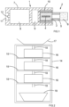
- FIG 1 shows schematically parts of a tobacco heating product with a susceptor.
- the tobacco heating product comprises an inductive heating device 1 which receives a smoking article (aerosol forming article) 2.
- the tobacco heating product is designed to produce an aerosol which is inhaled by the user.
- the smoking article 2 is wrapped in paper in a similar way to a conventional cigarette to form a rod-shaped article.
- the smoking article 2 comprises a tobacco column 3 with a metallic susceptor blade 4.
- the susceptor blade is made from a magnetically permeable and electrically conductive metallic material.
- the smoking article 2 may include a cooling/condensation element 5 and a particulate filter 6.
- the cooling/condensation element 5 may be in the form of a hollow cellulose acetate tube.
- Various other components may be present in the smoking article as well as or instead of those shown.
- the inductive heating device 1 comprises a housing 7, a battery 8, control electronics 9 and inductive heating source 10.
- the inductive heating source 10 may be for example a helically wound cylindrical inductor coil.
- the heating device may further include a docking port 11 with a docking pin 12 for recharging the battery 8.
- the battery 8 supplies power to the control electronics 9.
- the control electronics 9 produce an alternating current which is supplied to the inductive heating source 10.
- the inductive heating source 10 produces an alternating magnetic field, which induces an alternating magnetic field in the susceptor 4. This induced alternating magnetic field generates heat in the susceptor. At least some of the heat generated in the susceptor 4 is transferred to the tobacco column 3 to release an aerosol containing nicotine and flavours. This aerosol passed through the cooling element 5 and filter 6 and is inhaled by the user.
- the tobacco heating product may be, for example, as described in WO 2017/085242 . However, it will be appreciated that other types of tobacco heating product may be used instead.
- the tobacco column is typically in the form of a gathered sheet of crimped homogenised tobacco material.
- the susceptor strip is inserted into the tobacco column as part of the production process. This process typically involves producing a long cylindrical tobacco column with a steel strip (which will form the susceptor) running through the centre. The long tobacco column is then chopped up into smaller items of the required length for the smoking article. The various cylindrical components of the smoking article are then aligned and tightly wrapped in a wrapper such a cigarette paper.
- the smoking article may, for example, as described in WO 2015/177294 . However, it will be appreciated that other types of smoking article may be used instead.
- the process of forming the tobacco column may disturb the steel strip, or the steel strip may become damaged in the cutting process. Measurements may therefore be made as part of a quality assurance and quality control process.
- the positioning and accuracy of formation of the susceptor is a key quality measure in the production process, as are the physical attributes of other features within the rod.
- FIG. 2 shows parts of a test stack which may be used to perform various measurements on a succession of aerosol forming articles.
- the test stack is in the form of a cabinet 14 with a plurality of shelves 15.
- a measurement instrument 16 is located on each of the shelves.
- a hopper 17 is located at the top of the cabinet 14. The hopper 17 is connected to the top measurement instrument via a guide tube 18. Further guide tubes 18 connect each measurement instrument to the one below.
- a bucket 19 is provided at the bottom of the cabinet to collect the articles which have been tested.
- the top measurement instrument receives a succession of articles to be tested from the hopper 17.
- the measurement instrument carries out various measurements on each article. Once the measurements on an article are complete, that article is dropped through the guide tube 18 to the measurement instrument immediately below. That measurement instrument then carries out its own tests on the article. This process is repeated as the article travels downwards through the test stack, until it is dispensed into the bucket. Thus, a product under test drops under gravity from one shelf to another with a different test being carried out at each stage.
- the apparent width of the susceptor may vary depending on the orientation of the article. This variation could potentially lead to inaccurate results if the article is not correctly orientated.
- transmission imaging of the article to measure the position of the susceptor relative to the circumferential envelope paper and the circular ends of the tobacco segment may rely on prior knowledge of the orientation of the article.
- Figures 3(A) and 3(B) show side views of a smoking article in two different orientations.
- the smoking article 2 comprises a tobacco column 3 inside which there is a metallic susceptor strip 4.
- the smoking article may also contain a cooling/condensation element 5 and a particulate filter 6.
- the smoking article 2 is generally cylindrical with a longitudinal axis shown by the dashed lines in Figures 3(A) and 3(B) .
- Figure 3(A) shows an orientation in which the susceptor strip lies in a plane which is perpendicular to the plane of the paper
- Figure 3(B) shows an orientation in which the susceptor strip lies in a plane which is parallel to the plane of the paper.
- the article is rotated by 90° about its longitudinal axis relative to the orientation of Figure 3(A) .
- the susceptor strip is substantially flat, and has a width which is greater than its depth.
- the different orientations in Figures 3(A) and 3(B) result in a difference in the apparent dimensions of the susceptor.
- Figure 4 shows an end view of a smoking article 2 with a metal susceptor. In the arrangement shown, the susceptor 4 is correctly located at the centre of the tobacco column 3.
- Figures 5(A) to 5(C) illustrate some of the potential mis-formations of the susceptor that could be encountered and be the subject of quality assurance/quality control concerns.
- Figure 5(A) shows a curved susceptor
- Figure 5(B) shows a folded-over susceptor
- Figure 5(C) shows an off-centre susceptor
- Figure 5(D) shows a twisted susceptor.
- Such defects in the susceptor can lead to deficiencies in the heating process, such as uneven heating or no heating at the base of the tobacco rod.
- Embodiments of the invention are based on the realisation that, since the susceptor strip 4 is made from a magnetically permeable material, its magnetic properties can be used to orientate the susceptor strip, and hence the smoking article, to an applied magnetic field.
- Embodiments of the invention provide techniques for orientating a smoking article that use a strong magnetic field that interacts with the susceptor strip.
- a magnetic gradient is induced across both poles of the susceptor strip. This causes a rotation large enough to overcome the moment of inertia of the article when the article is free to turn, such as when dropped between measurement locations in a stack of test equipment.
- the result is an alignment of the susceptor strip with the magnetic field. This alignment takes place fast enough for the smoking article with its internal susceptor to be in alignment by the time it passes through the field.
- a typical application would be the measurement of rod characteristics in a physical test stack where measurement instruments are placed one above the other. After a measurement or loading from a hopper or automatically sampling from a making or combining machine the rod under test is dropped past a magnetic field to orient it for a specific measurement such as determining the susceptor width using x-ray analysis.
- a rod gate is incorporated into the system to stop and then release the rod while in the magnetic field which ensures optimisation of the alignment.
- a guide tube may be used to guide the passage of the rod through the magnetic field.
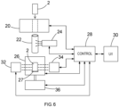
- Figure 6 shows parts of an apparatus for orientating a rod-shaped smoking article in an embodiment of the present invention.
- the arrangement of Figure 6 may be, for example, part of a measurement instrument such as a measurement instrument 16 in a test stack as shown in Figure 2 .
- the apparatus comprises rod gate 20, guide tube 22, electromagnet 24, vacuum chuck 26, control unit 28 and user interface 30.
- the rod gate 20 of Figure 6 is designed to receive successive rod-shaped smoking articles 2 and to release them in a controlled manner into the guide tube 22.
- the articles may be received, for example, from a hopper, or from a measurement instrument located above the rod gate, or from a sampling device which takes samples from a flow of articles.
- the rod gate 20 operates by applying a vacuum to the smoking article in order to hold it in place, and then removing the vacuum in order to release the article.
- a mechanical holding device such as a gripper or a shutter could be used to hold and release the article.
- the rod gate 20 operates under control of the control unit 28.
- the guide tube 22 is a hollow cylinder with an internal diameter which is slightly larger than the diameter of an article to be tested.
- the guide tube 22 allows a smoking article 2 to fall through it under the influence of gravity in a direction parallel to the longitudinal axis of the smoking article.
- the guide tube also allows rotation of the article about its longitudinal axis. However, the guide tube prevents the article from displacement in a direction perpendicular to its longitudinal axis, and from rotation other than about its longitudinal axis.
- the guide tube 22 is made from a non-magnetic material such as plastic.
- the electromagnet 24 is arranged to apply a controlled magnetic field to the guide tube 22. Since the guide tube is made from a non-magnetic material, the magnetic field passes through wall of the guide tube. The electromagnet 24 is activated by the control unit 28 such that the magnetic field is applied while a smoking article 2 is falling through the guide tube 22. As a consequence, the smoking article encounters the magnetic field as it passes through the guide tube. The magnetic field acts on the metallic susceptor 4 inside the smoking article 2 and causes the article to rotate about its longitudinal axis.
- the vacuum chuck 26 is arranged to receive a smoking article 2 which has passed through the guide tube 22, and to hold it in place using a vacuum.
- the vacuum chuck is located at the exit point of the guide tube 22, so that the orientation of the smoking article is maintained.
- the vacuum chuck 26 comprises a foot 27 on which the article 2 rests. A removeable vacuum is applied to the smoking article through the foot 27, in order to hold the article 2 in place. The vacuum is applied as the smoking article 2 exits the guide tube 22 and enters the vacuum chuck 26. The operation of the vacuum is controlled by the control unit 28.
- the control unit 28 is used to control the operation of the apparatus.
- the control unit 28 may be implemented as a software routine executing on a suitable processor, such as a personal computer.
- the control unit 28 is connected to the user interface 30.
- the user interface comprises an input device such as a keyboard and/or mouse and an output device such as a display.
- the user interface allows the user to input test and control parameters.
- the user interface also allows test results and other data to be provided to the user.
- the rod gate 20 receives successive smoking articles 2 and holds them at the top of the guide tube 22. At appropriate intervals, the rod gate releases a smoking article 2 into the guide tube 22. The released smoking article then drops through the guide tube 22.
- the magnetic field produced by the electromagnet 24 is activated. The strength of the magnetic field is matched to the article's moment of inertia. The magnetic field interacts with the susceptor strip 4 inside the smoking article 2 in order to align the susceptor strip with the magnetic field.
- the susceptor strip is made from a ferromagnetic material
- the presence of the external magnetic field will induce a temporary alignment of the magnetic domains within the susceptor material.
- the susceptor thus becomes a temporary magnet with its own north and south poles, which will then become aligned with the magnetic field produced by the electromagnet.
- the smoking article While it is in the guide tube, the smoking article is constrained except for rotational (and axial) movement.
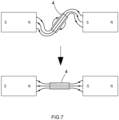
- the ferromagnetic material has a high permeability, and therefore presents a preferential path for the flux of the applied magnetic field. The smoking article will therefore rotate until the lines of flux of the magnetic field are able to take the shortest path via the susceptor strip. This principle is illustrated in Figure 7 .
- the distance and the strength of the magnetic field plays an important role in the success of the aligner.
- the tobacco in the rod could be compressed with a bias to one side of the cross-section of the rod if the field is too strong.
- the rod may not be aligned if the field is too weak.
- the strength of the magnetic field is chosen to be sufficient to rotate the article, but not so high as to cause any deformation of the tobacco.
- the strength of the magnetic field may be adjusted by the control unit 28 so that it is appropriate for the type of smoking article under test.
- the control unit may include a memory with a look-up table with different magnetic field strengths for different types of article.
- the user interface 30 may be used to select a particular article, and the control unit look up the required magnetic field strength for that article and adjust the applied magnetic field strength accordingly.
- the user interface may be used to control the magnetic field strength directly.
- the length of the drop through the guide tube 22 is chosen to be sufficient to allow time for the article to be rotated, but short enough to prevent the article from reaching a velocity which would reduce the accuracy of the orientation.
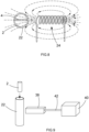
- Figure 8 shows a top view of the electromagnet 24 and the guide tube 22 as a smoking article 2 moves through the magnetic field.
- the electromagnet when energised, produces a magnetic field which passes through the wall of the guide tube 22 and interacts with the susceptor strip 4 in the smoking article. This causes the smoking article to rotate so that the susceptor strip is aligned with the magnetic field.
- Figure 9 illustrates an alternative embodiment using a permanent magnet 38 rather than an electromagnet to orientate the smoking article 2.
- the permanent magnet 38 may be a neodymium magnet, or any other appropriate type of magnet.
- an actuator such as a pneumatic cylinder 40 and rod 42 is used to move the magnet 38 into position.
- the actuator moves the magnet from a rest position to a position adjacent to or in contact with the guide tube when an article is to be orientated.
- the actuator moves the magnet away from the guide tube to the rest position at other times.
- the actuator operates under control of the control unit 28.
- Other parts of the apparatus may be the same as or similar to those shown in Figure 6 above.
- a U-shaped electromagnet or permanent magnet could be used in order to present a north pole to one side of the guide tube and a south pole to the other side, or separate magnets could be used on either side of the guide tube. This may help to produce the required lines of flux through the guide tube.
- the arrangements described above can be used to orientate an article under test as it passes through a test stack such as that shown in Figure 2 .
- the apparatus can be used to rotate an article to a required orientation prior to carrying out measurements which are orientation dependent.
- measurements may include, for example, transmission imaging, non-transmission imaging, compression tests (for example to measure hardness), laser tests (for example to measure ovality) or any other type of test to determine a physical property of the smoking article.
- the apparatus shown includes emitter 32, detector 34 and drive unit 36 which form part of a measurement instrument.
- the measurement instrument is an imaging system which is arranged to produce an image of the smoking article 2.
- the emitter 32 is an emitter of electromagnetic radiation, such as infrared, visible light, ultraviolet or X-rays.
- the detector 34 is arranged to detect the electromagnetic radiation emitted by the emitter 32 after imaging of the smoking article 2.
- the vacuum chuck 26 holds the smoking article 2 to one side of the electromagnetic radiation, to allow the article to be imaged.
- the drive unit 36 is arranged to adjust the orientation of the smoking article 2 relative to the emitter 32 and detector 34 to allow different images of the smoking article to be taken. This may be achieved through rotation of the article, longitudinal displacement of the smoking article, or both. Operation of the emitter 32, detector 34 and drive unit 36 is controlled by the control unit 28. Alternatively, if desired a separate control unit could be used to control the measurements.
- the imaging system shown in Figure 6 may be, for example, as described in International patent application number PCT/GB2019/051882 , or International patent publication number WO 2004/083834 . However, it will be appreciated that these types of imaging system are given by way of example only, and other types of measurement instrument may be used as well or instead.
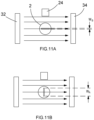
- Figure 10 illustrates operation of a measurement instrument in one embodiment.
- the measurement instrument comprises an emitter 32 and a detector 34, which may be in the form shown in Figure 6 .
- the emitter 32 is an x-ray source and the detector 34 is a flat panel x-ray detector (area image sensor), both of which are known in the art.
- the smoking article 2 is located between the emitter 32 and the detector 34.
- the x-ray radiation 38 passes through the smoking article and is detected by the panel array.
- the susceptor forms an image with a width W on the panel array.
- the magnet 24 is not energised.
- Figures 11(A) and 11(B) illustrate the measurement instrument with the smoking article in two different orientations. It can be seen that the apparent width of the susceptor strip can vary between W B when the strip is parallel to the x-rays and W A when the strip is perpendicular to the x-rays. Thus, when the magnet is not energised, the apparent width of the susceptor varies depending on the random orientation of the smoking article.
- Figure 12 illustrates the measurement instrument when the magnet 24 has been energised. Energising the magnet 24 orients the susceptor to the magnetic field. This allows a true measure of the width of the susceptor to be produced.
Landscapes
- Manufacturing Of Cigar And Cigarette Tobacco (AREA)
Description
- The present invention relates to techniques for orientating a rod-shaped smoking article, and in particular a rod-shaped smoking article containing an internal metal component. The invention has particular but not exclusive application with tobacco heating products containing a susceptor.
- Novel tobacco heating products (THPs) have started to appear on the marketplace. These products are characterised by the ability to heat a tobacco column without combustion or smouldering to release an aerosol containing nicotine and flavours. Various types of controlled heat source can be used to heat the tobacco column. These include an electrically heated rod or blade that is inserted into the tobacco, and an electrical heating system that surrounds the tobacco column.
- A disadvantage of inserting a blade into the tobacco column is a tendency of the blade to be broken. A further disadvantage is the accumulation of material on the blade from the tobacco being heated. On the other hand, an electrical heating system that surrounds the tobacco column may have a lower heating efficiency.
- To avoid these problems, a new type of tobacco heating product has been developed that includes within the tobacco column a metal blade or susceptor that is inductively heated by surrounding electronics. For example,
WO 2017/085242 discloses an inductive heating device for heating an aerosol-forming substrate comprising a susceptor. Such products avoid the need for an insertable blade that could be broken and the need to clean the heating element as this becomes a disposable item. - During the production of smoking articles such as aerosol forming articles for tobacco heating products it is necessary to monitor the quality of the articles. Measurements are therefore made as part of a quality assurance and quality control process. In the case of articles with an internal susceptor, the positioning and accuracy of formation of this susceptor is a key quality measure in the production process.
-
EP3461352A1 describes a device for processing articles in the tobacco processing industry of the type containing at least one body made of magnetic or magnetizable material, with at least one holding device for holding at least one such article. The holding device is designed in such a way that it allows the position of the article to be changed at least temporarily while the article is being held. A magnetization device generates a magnetic force that acts on the at least one body made of magnetic or magnetizable material in the article in order to bring the article into a defined position. - One challenge facing the quality assurance/quality control professional is that the measurement required may be orientation specific. For example, a measurement may need to be made where the internal susceptor is at right angles to a sensor or in line with a sensor. An example of such a requirement is the transmission imaging of the product to measure the position of the susceptor relative to the circumferential envelope paper and the circular ends of the tobacco segment. To measure a large number of articles with a precise orientation with respect to a sensor can be a time consuming, labour intensive task that is prone to error.
- It would therefore be desirable to provide a technique for automatically orientating the article such that it is in a known orientation for subsequent testing.
- According to one aspect of the present invention there is provided apparatus for orientating a rod-shaped smoking article according to claim 1.
- The present invention may provide the advantage that, by presenting the rod-shaped smoking article to the magnetic field in a manner which allows rotation of the article, it may be possible to orientate the article such that it is in a known orientation for subsequent testing.
- The rod-shaped smoking article may be any type of smoking article such as a conventional cigarette, an aerosol forming article for use with a tobacco heating product, a heat-not-burn stick or any similar product that contains material for combustion or heating. Preferably the rod-shaped smoking article comprises non-metallic material in which the metallic component is embedded.
- The rod-shaped smoking article may be an aerosol generating article in which the metal component is embedded in an aerosol forming substrate. The aerosol forming substrate may comprise tobacco and/or other organic materials such as herbal materials and/or other compounds which release an aerosol upon heating.
- The rod-shaped smoking article may be for use with an inductive heating device for inductively heating the metal component. Preferably the metal component comprises a ferromagnetic material, which is preferably embedded in a non-ferromagnetic material such as tobacco or other organic material. This may allow the component to be inductively heated and may facilitate rotation of the article under influence of the magnetic field.
- Preferably the metal component is substantially flat and/or has a width which is greater than its depth. For example, the metal component may be in the form of a blade or a strip. Thus, the metal component may be essentially planar, and/or may be without rotational symmetry. Thus, when a magnetic field is applied to the metal component, it may have a tendency to align with the applied field along its width. Preferably the metal component is a susceptor for heating an aerosol forming substrate such as a tobacco column.
- Preferably orientation of the rod-shaped smoking article is by rotation of the rod-shaped article under influence of the magnetic field. Preferably the rod-shaped smoking article has a longitudinal axis, and rotation of the rod-shaped smoking article is about its longitudinal axis. This may allow the article to acquire a known rotational orientation for subsequent testing.
- Preferably the magnetic field causes the rod-shaped smoking article to acquire a predetermined orientation. For example, the magnetic field may cause the article to rotate such that the metal component (for example a susceptor) is aligned with the magnetic field. Thus, the article may acquire a known orientation, which may allow orientation dependent measurements subsequently to be performed on the article.
- The means for producing a magnetic field may comprise a magnet. The magnet may be for example an electromagnet or a permanent magnetic. Preferably the means for producing a magnetic field is arranged to produce a substantially static magnetic field while the rod-shaped smoking article is presented to the magnetic field. This may facilitate rotation of the rod-shaped smoking article to a required orientation.
- The apparatus may be arranged such that the rod-shaped smoking article passes through the magnetic field, preferably in a direction parallel to its longitudinal axis. The apparatus is arranged to drop the rod-shaped smoking article through the magnetic field. Thus, the article may fall through the magnetic field under the influence of gravity. This may help to ensure that the article is free to turn as it passes through the magnetic field. Furthermore, this may allow the article to pass from one part of the apparatus to another without requiring an actuator. Alternatively, some other means for causing the article to pass through the magnetic field, such as a pressure differential, could be used as well or instead. However, the magnetic field is preferably used to rotate the article but not to move it along its longitudinal axis.
- The means for presenting the rod-shaped smoking article to the magnetic field may comprise a guide. The guide may be arranged such that the article can pass through the guide in a direction parallel to the longitudinal axis of the article and/or such that the article can rotate inside the guide about its longitudinal axis. However, the guide may constrain the article so as to prevent any substantial rotation of the article other than about its longitudinal axis and/or any substantial displacement of the article in a direction perpendicular to its longitudinal axis. This may help to ensure that the rod-shaped smoking article is correctly orientated.
- The guide may be, for example, a guide tube. The guide tube may be a tube through which the article can pass and/or within which the article can rotate. The guide tube may be, for example, a hollow cylinder. The guide tube may have an internal diameter which is slightly larger than the external diameter of the article and/or a length which is substantially the same as or longer than that of the article. However other guide means, such as a plurality of longitudinally extending rails spaced circumferentially about the article, are also envisaged.
- Preferably the guide comprises a non-magnetic material, in order to allow the magnetic field to enter the guide. Alternatively or in addition the guide may comprise one or more apertures, for example, to facilitate entry of the magnetic field into the guide. Preferably the means for producing a magnetic field is located adjacent to the guide. Thus, the apparatus may be arranged to produce a magnetic field inside the guide. The guide is preferably arranged to guide the rod-shaped smoking article as it passes through the magnetic field.
- Preferably the apparatus comprises means for causing the rod-shaped smoking article to pass through the guide. For example, the apparatus may be arranged to allow the rod-shaped smoking article to fall through the guide under the influence of gravity. This may help to ensure that the article is free to rotate as it passes through the magnetic field. Furthermore, this arrangement can allow the article to pass through the magnetic field without requiring an actuator for moving the article, which may reduce the number of components required. In addition, such an arrangement may facilitate use of the apparatus in a test stack in which an article under test is dropped between measurement locations.
- The apparatus may further comprise a hold and release mechanism for holding the rod-shaped smoking article and subsequently releasing it into the magnetic field. This may allow successive articles to be orientated at the appropriate intervals. Preferably, the hold and release mechanism is arranged to release the rod-shaped smoking article into the guide.
- However, in alternative arrangements, the apparatus may be arranged to apply the magnetic field to the rod-shaped smoking article while it is stationary, or while it is moving other than under the influence of gravity (for example, due to a pressure differential).
- The apparatus may further comprise a control unit for controlling operation of the apparatus. The control unit may be implemented, for example, as hardware or as a software routine running on a processor with associated memory.
- The control unit may be arranged to control the magnetic field which is presented to the rod-shaped smoking article. For example, the control unit may be arranged to apply the magnetic field when a smoking article is to be presented to the magnetic field. In this case the control unit may be arranged to remove the magnetic field at (at least some) other times. This may help to ensure that the magnetic field is only applied when required.
- The control unit may be arranged to control the strength of the magnetic field which is presented to the smoking article. This may allow the strength of the magnetic field to be adapted to the type of article under test. For example, the strength of the magnetic field may be adjusted to match the magnetic properties of a susceptor in the smoking article and/or the moment of inertia of the smoking article. In general, the strength of the magnetic field may be adjusted in order to ensure rotation of the article while avoiding any distortion of the article due to movement of the metal component in the article. However, the strength of the magnetic field may be substantially constant while it is presented to a smoking article.
- The control unit may be arranged to control the direction of the magnetic field which is presented to the smoking article. This can allow the apparatus to turn the smoking article into a plurality of different orientations. For example, different tests may require the smoking article to be in different orientations. However, the orientation of the magnetic field may be substantially constant while it is presented to a smoking article.
- Where the means for producing a magnetic field comprises an electromagnetic, the control means may be arranged to adjust a current through the electromagnetic, thereby controlling the magnetic field. Alternatively, where the means for producing a magnetic field comprises a permanent magnet, the apparatus may further comprise an actuator for moving the permanent magnetic. In this case the control unit may control the actuator in order to control the magnetic field which is encountered by the smoking article. For example, the actuator may change the distance of the magnet from the article and/or the direction of the magnet relative to the article. Such an actuator may also be used to adjust the distance and/or direction of an electromagnet relative to the smoking article.
- Where the apparatus comprises a hold and release mechanism, the control unit may be arranged to control operation of the hold and release mechanism. For example, the control unit may cause successive smoking articles to be held and then released at appropriate intervals. This may for example allow orientation of an article and/or tests to be performed on the article before the release of a subsequent article.
- Preferably the control unit is arranged to synchronise application of the magnetic field with release of the rod-shaped smoking article by the hold and release mechanism. For example, the control unit may be arranged to cause the magnetic field to be applied as the rod-shaped smoking article is released by the hold and release mechanism. This may help to ensure that the magnetic field is applied when required. For example, the magnetic field may be applied as the smoking article falls through a guide tube, but not at other times.
- The apparatus may further comprise a holding device for holding the rod-shaped smoking article after it has been orientated. Preferably, the holding device is arranged to receive the rod-shaped smoking article after it has passed through the magnetic field, and to hold the article in the orientation which it acquired when passing through the magnetic field. This can allow the article to be held in a known orientation for subsequent tests.
- The holding device may comprise, for example, means for applying a vacuum to the article in order to hold it in position. Alternatively or in addition the holding device may comprise means such as a gripper for holding the article mechanically.
- Where the apparatus comprises a control unit, the control unit may be arranged to control operation of the holding device. For example, the control means may be arranged to cause the holding device to hold the smoking article. This may allow the article to be held in a known orientation for testing. The control means may be arranged to release the article, for example after testing.
- In a preferred embodiment, the control unit is arranged to control operation of a hold and release mechanism, and to synchronise operation of the holding device with that of the hold and release mechanism. For example, the control unit may be arranged to apply a signal to the hold and release mechanism causing it to release a smoking article into the magnetic field, and then to apply a signal to the holding device causing it to hold the smoking article a predetermined time after it has been released by the hold and release mechanism. The predetermined time may correspond to the time taken for the article to fall from the hold and release mechanism through the magnetic field to the holding device. This can allow the article to rotate as it passes though the magnetic field, and then subsequently be held in the orientation which it acquired when passing through the magnetic field.
- The holding device may be arranged such that the rod-shaped smoking article can be rotated as it is being held. The rotation may be for example about its longitudinal axis. For example, the holding device may comprise a chuck, such as a vacuum chuck for holding and rotating the article. In this case the apparatus may further comprise drive means, such as a motor, for causing rotation of the holding device. This may allow different tests to be performed on the same smoking article when in different, known orientations. Rotation of the holding device may be controlled by the control unit.
- Alternatively, the holding device may be arranged to be rotated manually, for example, between a number of indexed rotational positions.
- The apparatus described above is preferably arranged to rotate the rod-shaped smoking article such that it acquires a known orientation for subsequent testing.
- According to another aspect of the present invention there is provided test apparatus comprising apparatus for orientating a rod-shaped smoking article in any of the forms described above and means for testing the rod-shaped smoking article. Preferably the means for testing the rod-shaped smoking article are separate from the means for producing a magnetic field and/or the means for presenting the rod-shaped smoking article to the magnetic field.
- Where the apparatus comprises a holding device, the holding device may be arranged to hold the rod-shaped smoking article during testing of the article by the testing means. The holding device may hold the article in the orientation which it acquired when passing through the magnetic field. This may allow the article to be held in a known orientation for testing.
- Preferably the testing means is arranged to perform at least one test which is sensitive to the orientation of the rod-shaped smoking article. For example, the testing means may be arranged to measure a dimension of one or more components of the article (such as the metal component) in one or more directions (such as two orthogonal directions).
- In one embodiment, the testing means is arranged to perform transmission imaging of the rod-shaped smoking article. For example, the testing means may be substantially as described in co-pending International patent application number
PCT/GB2019/051882 - The testing means may be arranged to detect a defect in the rod-shaped smoking article. For example, the testing means may be arranged to detect a defect in the metal component. Where the metal component is a susceptor, the testing means may be arranged to detect a defect in the susceptor. The defect may be, for example, one or more of: a misshaped susceptor; a misplaced susceptor; a missized susceptor; a missing susceptor; a curved susceptor; a folded-over susceptor; an off-centre susceptor; and a twisted susceptor.
- In a preferred embodiment, the test apparatus is part of a test stack arranged to drop the rod-shaped smoking article between a plurality of test locations. Thus, the apparatus for orientating the rod-shaped smoking article may be incorporated into the test stack, for example, between two testing positions. This may allow the apparatus to be located in an area where the article may anyway be dropped between two locations, thus providing a simple and convenient way of orientating the article for subsequent testing.
- Corresponding methods may also be provided. Thus, according to another aspect of the invention there is provided a method of orientating a rod-shaped smoking article according to
claim 15 - Features of one aspect of the invention may be provided with any other aspect. Apparatus features may be provided with method aspects and vice versa.
- Preferred features of the present invention will now be described, purely by way of example, with reference to the accompanying drawings, in which:
-
Figure 1 shows parts of a tobacco heating product with a susceptor; -
Figure 2 shows parts of a test stack; -
Figures 3(A) and 3(B) show side views of a smoking article; -
Figure 4 shows an end view of a smoking article with a metal susceptor; -
Figures 5(A) to 5(C) illustrate some potential mis-formations of a susceptor; -
Figure 6 shows parts of an apparatus for orientating a rod-shaped smoking article in an embodiment of the invention; -
Figure 7 illustrates a principle of operation of an embodiment of the invention; -
Figure 8 shows a top view of part of the apparatus ofFigure 6 ; -
Figure 9 illustrates an alternative embodiment with a permanent magnet; -
Figure 10 illustrates operation of a measurement instrument; -
Figures 11(A) and 11(B) illustrate a measurement instrument with a smoking article in two different orientations; and -
Figure 12 illustrates the measurement instrument when the magnet has been energised. -
Figure 1 shows schematically parts of a tobacco heating product with a susceptor. Referring toFigure 1 , the tobacco heating product comprises an inductive heating device 1 which receives a smoking article (aerosol forming article) 2. The tobacco heating product is designed to produce an aerosol which is inhaled by the user. - The
smoking article 2 is wrapped in paper in a similar way to a conventional cigarette to form a rod-shaped article. Thesmoking article 2 comprises atobacco column 3 with ametallic susceptor blade 4. The susceptor blade is made from a magnetically permeable and electrically conductive metallic material. Thesmoking article 2 may include a cooling/condensation element 5 and aparticulate filter 6. The cooling/condensation element 5 may be in the form of a hollow cellulose acetate tube. Various other components may be present in the smoking article as well as or instead of those shown. - In
Figure 1 , the inductive heating device 1 comprises ahousing 7, abattery 8,control electronics 9 andinductive heating source 10. Theinductive heating source 10 may be for example a helically wound cylindrical inductor coil. The heating device may further include adocking port 11 with adocking pin 12 for recharging thebattery 8. - In use, the
battery 8 supplies power to thecontrol electronics 9. Thecontrol electronics 9 produce an alternating current which is supplied to theinductive heating source 10. Theinductive heating source 10 produces an alternating magnetic field, which induces an alternating magnetic field in thesusceptor 4. This induced alternating magnetic field generates heat in the susceptor. At least some of the heat generated in thesusceptor 4 is transferred to thetobacco column 3 to release an aerosol containing nicotine and flavours. This aerosol passed through thecooling element 5 andfilter 6 and is inhaled by the user. - The tobacco heating product may be, for example, as described in
WO 2017/085242 . However, it will be appreciated that other types of tobacco heating product may be used instead. - In the smoking article described above the tobacco column is typically in the form of a gathered sheet of crimped homogenised tobacco material. The susceptor strip is inserted into the tobacco column as part of the production process. This process typically involves producing a long cylindrical tobacco column with a steel strip (which will form the susceptor) running through the centre. The long tobacco column is then chopped up into smaller items of the required length for the smoking article. The various cylindrical components of the smoking article are then aligned and tightly wrapped in a wrapper such a cigarette paper. The smoking article may, for example, as described in
WO 2015/177294 . However, it will be appreciated that other types of smoking article may be used instead. - It has been found that, during the manufacturing process, various defects may arise in the susceptor. For example, the process of forming the tobacco column may disturb the steel strip, or the steel strip may become damaged in the cutting process. Measurements may therefore be made as part of a quality assurance and quality control process. The positioning and accuracy of formation of the susceptor is a key quality measure in the production process, as are the physical attributes of other features within the rod.
-
Figure 2 shows parts of a test stack which may be used to perform various measurements on a succession of aerosol forming articles. Referring toFigure 2 , the test stack is in the form of acabinet 14 with a plurality ofshelves 15. Ameasurement instrument 16 is located on each of the shelves. Ahopper 17 is located at the top of thecabinet 14. Thehopper 17 is connected to the top measurement instrument via aguide tube 18.Further guide tubes 18 connect each measurement instrument to the one below. Abucket 19 is provided at the bottom of the cabinet to collect the articles which have been tested. - In operation, the top measurement instrument receives a succession of articles to be tested from the
hopper 17. The measurement instrument carries out various measurements on each article. Once the measurements on an article are complete, that article is dropped through theguide tube 18 to the measurement instrument immediately below. That measurement instrument then carries out its own tests on the article. This process is repeated as the article travels downwards through the test stack, until it is dispensed into the bucket. Thus, a product under test drops under gravity from one shelf to another with a different test being carried out at each stage. - One challenge arising during the quality assurance/quality control process is that the apparent width of the susceptor may vary depending on the orientation of the article. This variation could potentially lead to inaccurate results if the article is not correctly orientated. For example, transmission imaging of the article to measure the position of the susceptor relative to the circumferential envelope paper and the circular ends of the tobacco segment may rely on prior knowledge of the orientation of the article.
-
Figures 3(A) and 3(B) show side views of a smoking article in two different orientations. Referring toFigures 3(A) and 3(B) , thesmoking article 2 comprises atobacco column 3 inside which there is ametallic susceptor strip 4. The smoking article may also contain a cooling/condensation element 5 and aparticulate filter 6. Thesmoking article 2 is generally cylindrical with a longitudinal axis shown by the dashed lines inFigures 3(A) and 3(B) . -
Figure 3(A) shows an orientation in which the susceptor strip lies in a plane which is perpendicular to the plane of the paper, whileFigure 3(B) shows an orientation in which the susceptor strip lies in a plane which is parallel to the plane of the paper. Thus, in the orientation ofFigure 3(B) the article is rotated by 90° about its longitudinal axis relative to the orientation ofFigure 3(A) . FromFigures 3(A) and 3(B) it can be seen that the susceptor strip is substantially flat, and has a width which is greater than its depth. The different orientations inFigures 3(A) and 3(B) result in a difference in the apparent dimensions of the susceptor. -
Figure 4 shows an end view of asmoking article 2 with a metal susceptor. In the arrangement shown, thesusceptor 4 is correctly located at the centre of thetobacco column 3. -
Figures 5(A) to 5(C) illustrate some of the potential mis-formations of the susceptor that could be encountered and be the subject of quality assurance/quality control concerns.Figure 5(A) shows a curved susceptor;Figure 5(B) shows a folded-over susceptor;Figure 5(C) shows an off-centre susceptor; andFigure 5(D) shows a twisted susceptor. Such defects in the susceptor can lead to deficiencies in the heating process, such as uneven heating or no heating at the base of the tobacco rod. - Embodiments of the invention are based on the realisation that, since the
susceptor strip 4 is made from a magnetically permeable material, its magnetic properties can be used to orientate the susceptor strip, and hence the smoking article, to an applied magnetic field. - Embodiments of the invention provide techniques for orientating a smoking article that use a strong magnetic field that interacts with the susceptor strip. A magnetic gradient is induced across both poles of the susceptor strip. This causes a rotation large enough to overcome the moment of inertia of the article when the article is free to turn, such as when dropped between measurement locations in a stack of test equipment. The result is an alignment of the susceptor strip with the magnetic field. This alignment takes place fast enough for the smoking article with its internal susceptor to be in alignment by the time it passes through the field.
- A typical application would be the measurement of rod characteristics in a physical test stack where measurement instruments are placed one above the other. After a measurement or loading from a hopper or automatically sampling from a making or combining machine the rod under test is dropped past a magnetic field to orient it for a specific measurement such as determining the susceptor width using x-ray analysis. In practice a rod gate is incorporated into the system to stop and then release the rod while in the magnetic field which ensures optimisation of the alignment. A guide tube may be used to guide the passage of the rod through the magnetic field.
-
Figure 6 shows parts of an apparatus for orientating a rod-shaped smoking article in an embodiment of the present invention. The arrangement ofFigure 6 may be, for example, part of a measurement instrument such as ameasurement instrument 16 in a test stack as shown inFigure 2 . - Referring to
Figure 6 , the apparatus comprisesrod gate 20,guide tube 22,electromagnet 24,vacuum chuck 26,control unit 28 anduser interface 30. - The
rod gate 20 ofFigure 6 is designed to receive successive rod-shapedsmoking articles 2 and to release them in a controlled manner into theguide tube 22. The articles may be received, for example, from a hopper, or from a measurement instrument located above the rod gate, or from a sampling device which takes samples from a flow of articles. Therod gate 20 operates by applying a vacuum to the smoking article in order to hold it in place, and then removing the vacuum in order to release the article. Alternatively, a mechanical holding device, such as a gripper or a shutter could be used to hold and release the article. Therod gate 20 operates under control of thecontrol unit 28. - The
guide tube 22 is a hollow cylinder with an internal diameter which is slightly larger than the diameter of an article to be tested. Theguide tube 22 allows asmoking article 2 to fall through it under the influence of gravity in a direction parallel to the longitudinal axis of the smoking article. The guide tube also allows rotation of the article about its longitudinal axis. However, the guide tube prevents the article from displacement in a direction perpendicular to its longitudinal axis, and from rotation other than about its longitudinal axis. Theguide tube 22 is made from a non-magnetic material such as plastic. - The
electromagnet 24 is arranged to apply a controlled magnetic field to theguide tube 22. Since the guide tube is made from a non-magnetic material, the magnetic field passes through wall of the guide tube. Theelectromagnet 24 is activated by thecontrol unit 28 such that the magnetic field is applied while asmoking article 2 is falling through theguide tube 22. As a consequence, the smoking article encounters the magnetic field as it passes through the guide tube. The magnetic field acts on themetallic susceptor 4 inside thesmoking article 2 and causes the article to rotate about its longitudinal axis. - The
vacuum chuck 26 is arranged to receive asmoking article 2 which has passed through theguide tube 22, and to hold it in place using a vacuum. The vacuum chuck is located at the exit point of theguide tube 22, so that the orientation of the smoking article is maintained. Thevacuum chuck 26 comprises afoot 27 on which thearticle 2 rests. A removeable vacuum is applied to the smoking article through thefoot 27, in order to hold thearticle 2 in place. The vacuum is applied as thesmoking article 2 exits theguide tube 22 and enters thevacuum chuck 26. The operation of the vacuum is controlled by thecontrol unit 28. - The
control unit 28 is used to control the operation of the apparatus. Thecontrol unit 28 may be implemented as a software routine executing on a suitable processor, such as a personal computer. Thecontrol unit 28 is connected to theuser interface 30. The user interface comprises an input device such as a keyboard and/or mouse and an output device such as a display. The user interface allows the user to input test and control parameters. The user interface also allows test results and other data to be provided to the user. - In operation, the
rod gate 20 receivessuccessive smoking articles 2 and holds them at the top of theguide tube 22. At appropriate intervals, the rod gate releases asmoking article 2 into theguide tube 22. The released smoking article then drops through theguide tube 22. At the same time, the magnetic field produced by theelectromagnet 24 is activated. The strength of the magnetic field is matched to the article's moment of inertia. The magnetic field interacts with thesusceptor strip 4 inside thesmoking article 2 in order to align the susceptor strip with the magnetic field. Once thesmoking article 2 has passed through the guide tube, it is held in place by thevacuum chuck 26, in the orientation which it achieved while passing through the magnetic field. - As long the susceptor strip is made from a ferromagnetic material, the presence of the external magnetic field will induce a temporary alignment of the magnetic domains within the susceptor material. The susceptor thus becomes a temporary magnet with its own north and south poles, which will then become aligned with the magnetic field produced by the electromagnet. While it is in the guide tube, the smoking article is constrained except for rotational (and axial) movement. The ferromagnetic material has a high permeability, and therefore presents a preferential path for the flux of the applied magnetic field. The smoking article will therefore rotate until the lines of flux of the magnetic field are able to take the shortest path via the susceptor strip. This principle is illustrated in
Figure 7 . - The distance and the strength of the magnetic field plays an important role in the success of the aligner. The tobacco in the rod could be compressed with a bias to one side of the cross-section of the rod if the field is too strong. On the other hand, the rod may not be aligned if the field is too weak. Thus, the strength of the magnetic field is chosen to be sufficient to rotate the article, but not so high as to cause any deformation of the tobacco. The strength of the magnetic field may be adjusted by the
control unit 28 so that it is appropriate for the type of smoking article under test. For example, the control unit may include a memory with a look-up table with different magnetic field strengths for different types of article. In this case, theuser interface 30 may be used to select a particular article, and the control unit look up the required magnetic field strength for that article and adjust the applied magnetic field strength accordingly. Alternatively the user interface may be used to control the magnetic field strength directly. - As the velocity of the rod through the magnetic field increases (long drop) then the accuracy of orientation decreases. Thus, the length of the drop through the
guide tube 22 is chosen to be sufficient to allow time for the article to be rotated, but short enough to prevent the article from reaching a velocity which would reduce the accuracy of the orientation. -
Figure 8 shows a top view of theelectromagnet 24 and theguide tube 22 as asmoking article 2 moves through the magnetic field. Referring toFigure 8 , it can be seen that the electromagnet, when energised, produces a magnetic field which passes through the wall of theguide tube 22 and interacts with thesusceptor strip 4 in the smoking article. This causes the smoking article to rotate so that the susceptor strip is aligned with the magnetic field. -
Figure 9 illustrates an alternative embodiment using apermanent magnet 38 rather than an electromagnet to orientate thesmoking article 2. Thepermanent magnet 38 may be a neodymium magnet, or any other appropriate type of magnet. In this embodiment an actuator such as apneumatic cylinder 40 androd 42 is used to move themagnet 38 into position. The actuator moves the magnet from a rest position to a position adjacent to or in contact with the guide tube when an article is to be orientated. The actuator moves the magnet away from the guide tube to the rest position at other times. The actuator operates under control of thecontrol unit 28. Other parts of the apparatus may be the same as or similar to those shown inFigure 6 above. - If desired, a U-shaped electromagnet or permanent magnet could be used in order to present a north pole to one side of the guide tube and a south pole to the other side, or separate magnets could be used on either side of the guide tube. This may help to produce the required lines of flux through the guide tube.
- The arrangements described above can be used to orientate an article under test as it passes through a test stack such as that shown in
Figure 2 . In particular, the apparatus can be used to rotate an article to a required orientation prior to carrying out measurements which are orientation dependent. Such measurements may include, for example, transmission imaging, non-transmission imaging, compression tests (for example to measure hardness), laser tests (for example to measure ovality) or any other type of test to determine a physical property of the smoking article. - Referring back to
Figure 6 , the apparatus shown includesemitter 32,detector 34 and driveunit 36 which form part of a measurement instrument. In this example the measurement instrument is an imaging system which is arranged to produce an image of thesmoking article 2. Theemitter 32 is an emitter of electromagnetic radiation, such as infrared, visible light, ultraviolet or X-rays. Thedetector 34 is arranged to detect the electromagnetic radiation emitted by theemitter 32 after imaging of thesmoking article 2. Thevacuum chuck 26 holds thesmoking article 2 to one side of the electromagnetic radiation, to allow the article to be imaged. Thedrive unit 36 is arranged to adjust the orientation of thesmoking article 2 relative to theemitter 32 anddetector 34 to allow different images of the smoking article to be taken. This may be achieved through rotation of the article, longitudinal displacement of the smoking article, or both. Operation of theemitter 32,detector 34 and driveunit 36 is controlled by thecontrol unit 28. Alternatively, if desired a separate control unit could be used to control the measurements. - The imaging system shown in
Figure 6 may be, for example, as described in International patent application numberPCT/GB2019/051882 WO 2004/083834 . However, it will be appreciated that these types of imaging system are given by way of example only, and other types of measurement instrument may be used as well or instead. -
Figure 10 illustrates operation of a measurement instrument in one embodiment. Referring toFigure 10 , the measurement instrument comprises anemitter 32 and adetector 34, which may be in the form shown inFigure 6 . In this example theemitter 32 is an x-ray source and thedetector 34 is a flat panel x-ray detector (area image sensor), both of which are known in the art. Thesmoking article 2 is located between theemitter 32 and thedetector 34. Thex-ray radiation 38 passes through the smoking article and is detected by the panel array. The susceptor forms an image with a width W on the panel array. In the arrangement shown themagnet 24 is not energised. -
Figures 11(A) and 11(B) illustrate the measurement instrument with the smoking article in two different orientations. It can be seen that the apparent width of the susceptor strip can vary between WB when the strip is parallel to the x-rays and WA when the strip is perpendicular to the x-rays. Thus, when the magnet is not energised, the apparent width of the susceptor varies depending on the random orientation of the smoking article. -
Figure 12 illustrates the measurement instrument when themagnet 24 has been energised. Energising themagnet 24 orients the susceptor to the magnetic field. This allows a true measure of the width of the susceptor to be produced. - It will be appreciated that embodiments of the invention have been described above by way of example only, and variations in detail are possible. Although the invention has been described for use with a tobacco heating product with an internal susceptor, other types of smoking article could be used instead. For example, rather than containing tobacco, the smoking product may contain other organic materials or herbs. Furthermore, the exact construction of the smoking article may vary, and is described above for illustrative purposes only. The invention may also be used with other types of smoking article which contain metallic components. Other variations in detail will be apparent to the skilled person.
Claims (15)
- Apparatus for orientating a rod-shaped smoking article (2) containing a metal component (4), the apparatus comprising:means (24) for producing a magnetic field; andmeans (20, 22) for presenting the rod-shaped smoking article (2) to the magnetic field in a manner which allows rotation of the rod-shaped smoking article;characterised in that the apparatus is arranged to drop the rod-shaped smoking article (2) through the magnetic field.
- Apparatus according to claim 1, wherein the metal component (4) is a susceptor for heating an aerosol forming substrate.
- Apparatus according to claim 1 or 2, wherein the rotation of the rod-shaped smoking article (2) is about its longitudinal axis.
- Apparatus according to any of the preceding claims, wherein the magnetic field causes the rod-shaped smoking article (2) to acquire a predetermined orientation.
- Apparatus according to any of the preceding claims, wherein the means for presenting the rod-shaped smoking article (2) to the magnetic field comprises a guide (22), and wherein the means (24) for producing a magnetic field is located adjacent to the guide.
- Apparatus according to any of the preceding claims, further comprising a hold and release mechanism (20) for holding the rod-shaped smoking article (2) and subsequently releasing it into the magnetic field.
- Apparatus according to claim 6 when dependent on claim 5, wherein the hold and release mechanism (20) is arranged to release the rod-shaped smoking article (2) into the guide (22).
- Apparatus according to any of the preceding claims, further comprising a control unit (28) for controlling operation of the apparatus, wherein the control unit (28) is arranged to apply the magnetic field when a smoking article (2) is to be presented to the magnetic field.
- Apparatus according to claim 8 when dependent on claim 6, wherein the control unit (28) is arranged to control operation of the hold and release mechanism (20) and preferably to synchronise application of the magnetic field with release of the rod-shaped smoking article (2) by the hold and release mechanism (20).
- Apparatus according to any of the preceding claims, further comprising a holding device (26) arranged to receive the rod-shaped smoking article (2) after it has passed through the magnetic field, and to hold the article (2) in the orientation which it acquired when passing through the magnetic field.
- Apparatus according to claim 10 when dependent on claim 8, where the control unit (28) is arranged to control the holding device (26), and preferably to synchronise operation of the holding device with that of the hold and release mechanism (20), wherein the holding device (26) is preferably arranged such that the rod-shaped smoking article (2) can be rotated.
- Test apparatus comprising an apparatus for orientating a rod-shaped smoking article (2) according to any of the preceding claims and means (32, 34) for testing the rod-shaped smoking article.
- Test apparatus according to claim 12 when dependent on claim 10, wherein the holding device (26) is arranged to hold the rod-shaped smoking article (2) during testing of the article by the testing means.
- Test apparatus according to claim 12 or 13, wherein the testing means is arranged to perform transmission imaging of the rod-shaped smoking article and/or wherein the apparatus is part of a test stack arranged to drop the rod-shaped smoking article (2) between a plurality of test locations (16).
- A method of orientating a rod-shaped smoking article (2) containing a metal component (4), the method comprising:producing a magnetic field;presenting the rod-shaped smoking article to the magnetic field; androtating the rod-shaped article under influence of the magnetic field;characterised in that the rod-shaped smoking article (2) is dropped through the magnetic field.
Applications Claiming Priority (2)
| Application Number | Priority Date | Filing Date | Title |
|---|---|---|---|
| GBGB1917430.9A GB201917430D0 (en) | 2019-11-29 | 2019-11-29 | Orientating a rod-shaped article |
| PCT/GB2020/053024 WO2021105692A1 (en) | 2019-11-29 | 2020-11-27 | Orientating a rod-shaped article |
Publications (2)
| Publication Number | Publication Date |
|---|---|
| EP4064878A1 EP4064878A1 (en) | 2022-10-05 |
| EP4064878B1 true EP4064878B1 (en) | 2024-10-16 |
Family
ID=69147079
Family Applications (1)
| Application Number | Title | Priority Date | Filing Date |
|---|---|---|---|
| EP20825160.3A Active EP4064878B1 (en) | 2019-11-29 | 2020-11-27 | Orientating a rod-shaped article |
Country Status (5)
| Country | Link |
|---|---|
| US (1) | US20230337746A1 (en) |
| EP (1) | EP4064878B1 (en) |
| CN (1) | CN114745974B (en) |
| GB (1) | GB201917430D0 (en) |
| WO (1) | WO2021105692A1 (en) |
Families Citing this family (1)
| Publication number | Priority date | Publication date | Assignee | Title |
|---|---|---|---|---|
| PL4531606T3 (en) * | 2022-05-27 | 2026-04-13 | Philip Morris Products S.A. | Detecting segments for aerosol-generating articles with two consecutive sensors |
Family Cites Families (15)
| Publication number | Priority date | Publication date | Assignee | Title |
|---|---|---|---|---|
| GB544478A (en) * | 1940-07-13 | 1942-04-15 | Felix Frederic Ruau | Improvements in or relating to apparatus for testing, sorting or grading articles |
| CH241439A (en) * | 1942-07-16 | 1946-03-15 | Molins Machine Co Ltd | Apparatus for checking articles produced in bulk. |
| US5613505A (en) * | 1992-09-11 | 1997-03-25 | Philip Morris Incorporated | Inductive heating systems for smoking articles |
| GB0306468D0 (en) | 2003-03-20 | 2003-04-23 | Molins Plc | A method and apparatus for determining one or more physical properties of a rolled smoking article or filter rod |
| WO2014015924A1 (en) * | 2012-07-23 | 2014-01-30 | Philip Morris Products S.A. | Apparatus and method for the disassembly of rod-shaped articles |
| AU2015261847B2 (en) | 2014-05-21 | 2019-05-02 | Philip Morris Products S.A. | Aerosol-generating article with multi-material susceptor |
| ES2676049T3 (en) * | 2014-08-22 | 2018-07-16 | Sicpa Holding Sa | Apparatus and methods for producing layers of optical effects |
| CN107750127B (en) * | 2015-05-21 | 2021-01-08 | 菲利普莫里斯生产公司 | Method and apparatus for manufacturing inductively heatable tobacco products |
| CN106325353B (en) * | 2015-06-17 | 2017-10-17 | 深圳市新宜康科技有限公司 | Utilize the electronic cigarette heating power control method and its control device of Hall effect |
| US20170055575A1 (en) * | 2015-08-31 | 2017-03-02 | British American Tobacco (Investments) Limited | Material for use with apparatus for heating smokable material |
| US20170055580A1 (en) * | 2015-08-31 | 2017-03-02 | British American Tobacco (Investments) Limited | Apparatus for heating smokable material |
| US20170119048A1 (en) * | 2015-10-30 | 2017-05-04 | British American Tobacco (Investments) Limited | Article for Use with Apparatus for Heating Smokable Material |
| WO2017085242A1 (en) | 2015-11-19 | 2017-05-26 | Philip Morris Products S.A. | Inductive heating device for heating an aerosol-forming substrate |
| ES2924628T3 (en) * | 2016-12-29 | 2022-10-10 | Philip Morris Products Sa | Method and apparatus for producing a component of an aerosol generating article |
| DE102017122752A1 (en) * | 2017-09-29 | 2019-04-04 | Hauni Maschinenbau Gmbh | Device for processing articles of the tobacco processing industry |
-
2019
- 2019-11-29 GB GBGB1917430.9A patent/GB201917430D0/en not_active Ceased
-
2020
- 2020-11-27 CN CN202080082999.2A patent/CN114745974B/en active Active
- 2020-11-27 EP EP20825160.3A patent/EP4064878B1/en active Active
- 2020-11-27 US US17/787,393 patent/US20230337746A1/en not_active Abandoned
- 2020-11-27 WO PCT/GB2020/053024 patent/WO2021105692A1/en not_active Ceased
Also Published As
| Publication number | Publication date |
|---|---|
| GB201917430D0 (en) | 2020-01-15 |
| US20230337746A1 (en) | 2023-10-26 |
| WO2021105692A1 (en) | 2021-06-03 |
| EP4064878A1 (en) | 2022-10-05 |
| CN114745974A (en) | 2022-07-12 |
| CN114745974B (en) | 2023-10-31 |
Similar Documents
| Publication | Publication Date | Title |
|---|---|---|
| KR900002496B1 (en) | Wear detection and detection method of ferromagnetic material | |
| US20040257072A1 (en) | Dual-sensitivity eddy current test probe | |
| JP3877344B2 (en) | Electronic article monitoring apparatus having high tag deactivation function | |
| US9638668B2 (en) | Surface property inspection apparatus, surface property inspection system, and surface property inspection method | |
| EP4081061B1 (en) | Method and apparatus for inspecting an inductively heatable aerosol-generating article for the presence of a susceptor and a desired article alignment | |
| CN102520379B (en) | Equipment and method for detecting temperature coefficient of remanence | |
| US20070222438A1 (en) | Electromagnetic flaw detection apparatus for inspection of a tubular | |
| US20230337746A1 (en) | Orientating a rod-shaped article | |
| CN109564192A (en) | The measuring device and method of conducting element in product and the machine for manufacturing the tobacco industry product for identification | |
| US20140002071A1 (en) | Probe for analyzing an assembly of rods or tubes | |
| CN115802907A (en) | Oriented tobacco product | |
| JP4903349B2 (en) | Detection of abnormalities in objects made of conductive materials | |
| JPS5839283B2 (en) | Thickness gauge for measuring sheet-like objects | |
| JP5428006B2 (en) | Magnetic foreign matter detector | |
| JPH0335624B2 (en) | ||
| CN107076804A (en) | Fast Magnetic Hot Spot Detector | |
| JP4822540B2 (en) | Local magnetization / magnetic field measurement equipment | |
| JP4644093B2 (en) | Component mounting machine, component counting method and component counting program | |
| KR100738321B1 (en) | Magnetic moment measuring device | |
| RU2815471C1 (en) | Checking system for packaging machine with recognition of twisted sticks | |
| JPH0342629B2 (en) | ||
| CN112740025B (en) | Method and device for detecting abnormal portion of material by eddy current | |
| JPH07294488A (en) | Residual magnetism measurement method | |
| CN108459072B (en) | Metal damage remote detection terminal based on electromagnetic conduction | |
| JPS5848617Y2 (en) | Sensitivity setting rod |
Legal Events
| Date | Code | Title | Description |
|---|---|---|---|
| STAA | Information on the status of an ep patent application or granted ep patent |
Free format text: STATUS: UNKNOWN |
|
| STAA | Information on the status of an ep patent application or granted ep patent |
Free format text: STATUS: THE INTERNATIONAL PUBLICATION HAS BEEN MADE |
|
| PUAI | Public reference made under article 153(3) epc to a published international application that has entered the european phase |
Free format text: ORIGINAL CODE: 0009012 |
|
| STAA | Information on the status of an ep patent application or granted ep patent |
Free format text: STATUS: REQUEST FOR EXAMINATION WAS MADE |
|
| 17P | Request for examination filed |
Effective date: 20220504 |
|
| AK | Designated contracting states |
Kind code of ref document: A1 Designated state(s): AL AT BE BG CH CY CZ DE DK EE ES FI FR GB GR HR HU IE IS IT LI LT LU LV MC MK MT NL NO PL PT RO RS SE SI SK SM TR |
|
| DAV | Request for validation of the european patent (deleted) | ||
| DAX | Request for extension of the european patent (deleted) | ||
| GRAP | Despatch of communication of intention to grant a patent |
Free format text: ORIGINAL CODE: EPIDOSNIGR1 |
|
| STAA | Information on the status of an ep patent application or granted ep patent |
Free format text: STATUS: GRANT OF PATENT IS INTENDED |
|
| INTG | Intention to grant announced |
Effective date: 20240514 |
|
| GRAS | Grant fee paid |
Free format text: ORIGINAL CODE: EPIDOSNIGR3 |
|
| GRAA | (expected) grant |
Free format text: ORIGINAL CODE: 0009210 |
|
| STAA | Information on the status of an ep patent application or granted ep patent |
Free format text: STATUS: THE PATENT HAS BEEN GRANTED |
|
| AK | Designated contracting states |
Kind code of ref document: B1 Designated state(s): AL AT BE BG CH CY CZ DE DK EE ES FI FR GB GR HR HU IE IS IT LI LT LU LV MC MK MT NL NO PL PT RO RS SE SI SK SM TR |
|
| REG | Reference to a national code |
Ref country code: GB Ref legal event code: FG4D |
|
| REG | Reference to a national code |
Ref country code: CH Ref legal event code: EP Ref country code: DE Ref legal event code: R096 Ref document number: 602020039655 Country of ref document: DE |
|
| REG | Reference to a national code |
Ref country code: IE Ref legal event code: FG4D |
|
| REG | Reference to a national code |
Ref country code: LT Ref legal event code: MG9D |
|
| REG | Reference to a national code |
Ref country code: NL Ref legal event code: MP Effective date: 20241016 |
|
| REG | Reference to a national code |
Ref country code: AT Ref legal event code: MK05 Ref document number: 1732158 Country of ref document: AT Kind code of ref document: T Effective date: 20241016 |
|
| PG25 | Lapsed in a contracting state [announced via postgrant information from national office to epo] |
Ref country code: NL Free format text: LAPSE BECAUSE OF FAILURE TO SUBMIT A TRANSLATION OF THE DESCRIPTION OR TO PAY THE FEE WITHIN THE PRESCRIBED TIME-LIMIT Effective date: 20241016 |
|
| PG25 | Lapsed in a contracting state [announced via postgrant information from national office to epo] |
Ref country code: NL Free format text: LAPSE BECAUSE OF FAILURE TO SUBMIT A TRANSLATION OF THE DESCRIPTION OR TO PAY THE FEE WITHIN THE PRESCRIBED TIME-LIMIT Effective date: 20241016 |
|
| PG25 | Lapsed in a contracting state [announced via postgrant information from national office to epo] |
Ref country code: HR Free format text: LAPSE BECAUSE OF FAILURE TO SUBMIT A TRANSLATION OF THE DESCRIPTION OR TO PAY THE FEE WITHIN THE PRESCRIBED TIME-LIMIT Effective date: 20241016 Ref country code: PT Free format text: LAPSE BECAUSE OF FAILURE TO SUBMIT A TRANSLATION OF THE DESCRIPTION OR TO PAY THE FEE WITHIN THE PRESCRIBED TIME-LIMIT Effective date: 20250217 Ref country code: IS Free format text: LAPSE BECAUSE OF FAILURE TO SUBMIT A TRANSLATION OF THE DESCRIPTION OR TO PAY THE FEE WITHIN THE PRESCRIBED TIME-LIMIT Effective date: 20250216 |
|
| PG25 | Lapsed in a contracting state [announced via postgrant information from national office to epo] |
Ref country code: FI Free format text: LAPSE BECAUSE OF FAILURE TO SUBMIT A TRANSLATION OF THE DESCRIPTION OR TO PAY THE FEE WITHIN THE PRESCRIBED TIME-LIMIT Effective date: 20241016 |
|
| PG25 | Lapsed in a contracting state [announced via postgrant information from national office to epo] |
Ref country code: BG Free format text: LAPSE BECAUSE OF FAILURE TO SUBMIT A TRANSLATION OF THE DESCRIPTION OR TO PAY THE FEE WITHIN THE PRESCRIBED TIME-LIMIT Effective date: 20241016 |
|
| PG25 | Lapsed in a contracting state [announced via postgrant information from national office to epo] |
Ref country code: ES Free format text: LAPSE BECAUSE OF FAILURE TO SUBMIT A TRANSLATION OF THE DESCRIPTION OR TO PAY THE FEE WITHIN THE PRESCRIBED TIME-LIMIT Effective date: 20241016 |
|
| PG25 | Lapsed in a contracting state [announced via postgrant information from national office to epo] |
Ref country code: NO Free format text: LAPSE BECAUSE OF FAILURE TO SUBMIT A TRANSLATION OF THE DESCRIPTION OR TO PAY THE FEE WITHIN THE PRESCRIBED TIME-LIMIT Effective date: 20250116 |
|
| PG25 | Lapsed in a contracting state [announced via postgrant information from national office to epo] |
Ref country code: LV Free format text: LAPSE BECAUSE OF FAILURE TO SUBMIT A TRANSLATION OF THE DESCRIPTION OR TO PAY THE FEE WITHIN THE PRESCRIBED TIME-LIMIT Effective date: 20241016 Ref country code: AT Free format text: LAPSE BECAUSE OF FAILURE TO SUBMIT A TRANSLATION OF THE DESCRIPTION OR TO PAY THE FEE WITHIN THE PRESCRIBED TIME-LIMIT Effective date: 20241016 Ref country code: GR Free format text: LAPSE BECAUSE OF FAILURE TO SUBMIT A TRANSLATION OF THE DESCRIPTION OR TO PAY THE FEE WITHIN THE PRESCRIBED TIME-LIMIT Effective date: 20250117 |
|
| PG25 | Lapsed in a contracting state [announced via postgrant information from national office to epo] |
Ref country code: PL Free format text: LAPSE BECAUSE OF FAILURE TO SUBMIT A TRANSLATION OF THE DESCRIPTION OR TO PAY THE FEE WITHIN THE PRESCRIBED TIME-LIMIT Effective date: 20241016 |
|
| PG25 | Lapsed in a contracting state [announced via postgrant information from national office to epo] |
Ref country code: RS Free format text: LAPSE BECAUSE OF FAILURE TO SUBMIT A TRANSLATION OF THE DESCRIPTION OR TO PAY THE FEE WITHIN THE PRESCRIBED TIME-LIMIT Effective date: 20250116 |
|
| PG25 | Lapsed in a contracting state [announced via postgrant information from national office to epo] |
Ref country code: SM Free format text: LAPSE BECAUSE OF FAILURE TO SUBMIT A TRANSLATION OF THE DESCRIPTION OR TO PAY THE FEE WITHIN THE PRESCRIBED TIME-LIMIT Effective date: 20241016 |
|
| PG25 | Lapsed in a contracting state [announced via postgrant information from national office to epo] |
Ref country code: MC Free format text: LAPSE BECAUSE OF FAILURE TO SUBMIT A TRANSLATION OF THE DESCRIPTION OR TO PAY THE FEE WITHIN THE PRESCRIBED TIME-LIMIT Effective date: 20241016 |
|
| PG25 | Lapsed in a contracting state [announced via postgrant information from national office to epo] |
Ref country code: DK Free format text: LAPSE BECAUSE OF FAILURE TO SUBMIT A TRANSLATION OF THE DESCRIPTION OR TO PAY THE FEE WITHIN THE PRESCRIBED TIME-LIMIT Effective date: 20241016 |
|
| PG25 | Lapsed in a contracting state [announced via postgrant information from national office to epo] |
Ref country code: LU Free format text: LAPSE BECAUSE OF NON-PAYMENT OF DUE FEES Effective date: 20241127 |
|
| REG | Reference to a national code |
Ref country code: DE Ref legal event code: R097 Ref document number: 602020039655 Country of ref document: DE |
|
| PG25 | Lapsed in a contracting state [announced via postgrant information from national office to epo] |
Ref country code: EE Free format text: LAPSE BECAUSE OF FAILURE TO SUBMIT A TRANSLATION OF THE DESCRIPTION OR TO PAY THE FEE WITHIN THE PRESCRIBED TIME-LIMIT Effective date: 20241016 |
|
| PG25 | Lapsed in a contracting state [announced via postgrant information from national office to epo] |
Ref country code: RO Free format text: LAPSE BECAUSE OF FAILURE TO SUBMIT A TRANSLATION OF THE DESCRIPTION OR TO PAY THE FEE WITHIN THE PRESCRIBED TIME-LIMIT Effective date: 20241016 |
|
| PG25 | Lapsed in a contracting state [announced via postgrant information from national office to epo] |
Ref country code: SK Free format text: LAPSE BECAUSE OF FAILURE TO SUBMIT A TRANSLATION OF THE DESCRIPTION OR TO PAY THE FEE WITHIN THE PRESCRIBED TIME-LIMIT Effective date: 20241016 |
|
| PG25 | Lapsed in a contracting state [announced via postgrant information from national office to epo] |
Ref country code: CZ Free format text: LAPSE BECAUSE OF FAILURE TO SUBMIT A TRANSLATION OF THE DESCRIPTION OR TO PAY THE FEE WITHIN THE PRESCRIBED TIME-LIMIT Effective date: 20241016 |
|
| PLBE | No opposition filed within time limit |
Free format text: ORIGINAL CODE: 0009261 |
|
| STAA | Information on the status of an ep patent application or granted ep patent |
Free format text: STATUS: NO OPPOSITION FILED WITHIN TIME LIMIT |
|
| REG | Reference to a national code |
Ref country code: BE Ref legal event code: MM Effective date: 20241130 |
|
| PG25 | Lapsed in a contracting state [announced via postgrant information from national office to epo] |
Ref country code: SE Free format text: LAPSE BECAUSE OF FAILURE TO SUBMIT A TRANSLATION OF THE DESCRIPTION OR TO PAY THE FEE WITHIN THE PRESCRIBED TIME-LIMIT Effective date: 20241016 |
|
| 26N | No opposition filed |
Effective date: 20250717 |
|
| PG25 | Lapsed in a contracting state [announced via postgrant information from national office to epo] |
Ref country code: BE Free format text: LAPSE BECAUSE OF NON-PAYMENT OF DUE FEES Effective date: 20241130 |
|
| PG25 | Lapsed in a contracting state [announced via postgrant information from national office to epo] |
Ref country code: IE Free format text: LAPSE BECAUSE OF NON-PAYMENT OF DUE FEES Effective date: 20241127 |
|
| REG | Reference to a national code |
Ref country code: CH Ref legal event code: U11 Free format text: ST27 STATUS EVENT CODE: U-0-0-U10-U11 (AS PROVIDED BY THE NATIONAL OFFICE) Effective date: 20251209 |
|
| PGFP | Annual fee paid to national office [announced via postgrant information from national office to epo] |
Ref country code: DE Payment date: 20251211 Year of fee payment: 6 |
|
| PGFP | Annual fee paid to national office [announced via postgrant information from national office to epo] |
Ref country code: GB Payment date: 20251128 Year of fee payment: 6 |
|
| PGFP | Annual fee paid to national office [announced via postgrant information from national office to epo] |
Ref country code: IT Payment date: 20251128 Year of fee payment: 6 |
|
| PGFP | Annual fee paid to national office [announced via postgrant information from national office to epo] |
Ref country code: FR Payment date: 20251128 Year of fee payment: 6 |
|
| PGFP | Annual fee paid to national office [announced via postgrant information from national office to epo] |
Ref country code: CH Payment date: 20251209 Year of fee payment: 6 |
|
| PG25 | Lapsed in a contracting state [announced via postgrant information from national office to epo] |
Ref country code: HU Free format text: LAPSE BECAUSE OF FAILURE TO SUBMIT A TRANSLATION OF THE DESCRIPTION OR TO PAY THE FEE WITHIN THE PRESCRIBED TIME-LIMIT; INVALID AB INITIO Effective date: 20201127 |
|
| PG25 | Lapsed in a contracting state [announced via postgrant information from national office to epo] |
Ref country code: CY Free format text: LAPSE BECAUSE OF FAILURE TO SUBMIT A TRANSLATION OF THE DESCRIPTION OR TO PAY THE FEE WITHIN THE PRESCRIBED TIME-LIMIT; INVALID AB INITIO Effective date: 20201127 |