EP4064715B1 - Peripheral bus video communication using internet protocol - Google Patents
Peripheral bus video communication using internet protocol Download PDFInfo
- Publication number
- EP4064715B1 EP4064715B1 EP22173389.2A EP22173389A EP4064715B1 EP 4064715 B1 EP4064715 B1 EP 4064715B1 EP 22173389 A EP22173389 A EP 22173389A EP 4064715 B1 EP4064715 B1 EP 4064715B1
- Authority
- EP
- European Patent Office
- Prior art keywords
- user device
- video
- camera
- peripheral bus
- control
- Prior art date
- Legal status (The legal status is an assumption and is not a legal conclusion. Google has not performed a legal analysis and makes no representation as to the accuracy of the status listed.)
- Active
Links
Images


Classifications
-
- H—ELECTRICITY
- H04—ELECTRIC COMMUNICATION TECHNIQUE
- H04N—PICTORIAL COMMUNICATION, e.g. TELEVISION
- H04N7/00—Television systems
- H04N7/14—Systems for two-way working
- H04N7/15—Conference systems
-
- H—ELECTRICITY
- H04—ELECTRIC COMMUNICATION TECHNIQUE
- H04N—PICTORIAL COMMUNICATION, e.g. TELEVISION
- H04N1/00—Scanning, transmission or reproduction of documents or the like, e.g. facsimile transmission; Details thereof
- H04N1/00127—Connection or combination of a still picture apparatus with another apparatus, e.g. for storage, processing or transmission of still picture signals or of information associated with a still picture
- H04N1/00204—Connection or combination of a still picture apparatus with another apparatus, e.g. for storage, processing or transmission of still picture signals or of information associated with a still picture with a digital computer or a digital computer system, e.g. an internet server
- H04N1/00209—Transmitting or receiving image data, e.g. facsimile data, via a computer, e.g. using e-mail, a computer network, the internet, I-fax
- H04N1/00214—Transmitting or receiving image data, e.g. facsimile data, via a computer, e.g. using e-mail, a computer network, the internet, I-fax details of transmission
- H04N1/00217—Transmitting or receiving image data, e.g. facsimile data, via a computer, e.g. using e-mail, a computer network, the internet, I-fax details of transmission only involving computer data transmission protocols, e.g. SMTP, WAP or HTTP
-
- G—PHYSICS
- G06—COMPUTING OR CALCULATING; COUNTING
- G06F—ELECTRIC DIGITAL DATA PROCESSING
- G06F13/00—Interconnection of, or transfer of information or other signals between, memories, input/output devices or central processing units
- G06F13/14—Handling requests for interconnection or transfer
- G06F13/16—Handling requests for interconnection or transfer for access to memory bus
- G06F13/1668—Details of memory controller
- G06F13/1673—Details of memory controller using buffers
-
- G—PHYSICS
- G06—COMPUTING OR CALCULATING; COUNTING
- G06F—ELECTRIC DIGITAL DATA PROCESSING
- G06F13/00—Interconnection of, or transfer of information or other signals between, memories, input/output devices or central processing units
- G06F13/38—Information transfer, e.g. on bus
- G06F13/42—Bus transfer protocol, e.g. handshake; Synchronisation
- G06F13/4282—Bus transfer protocol, e.g. handshake; Synchronisation on a serial bus, e.g. I2C bus, SPI bus
-
- H—ELECTRICITY
- H04—ELECTRIC COMMUNICATION TECHNIQUE
- H04L—TRANSMISSION OF DIGITAL INFORMATION, e.g. TELEGRAPHIC COMMUNICATION
- H04L12/00—Data switching networks
- H04L12/28—Data switching networks characterised by path configuration, e.g. LAN [Local Area Networks] or WAN [Wide Area Networks]
- H04L12/2803—Home automation networks
- H04L12/283—Processing of data at an internetworking point of a home automation network
- H04L12/2836—Protocol conversion between an external network and a home network
-
- H—ELECTRICITY
- H04—ELECTRIC COMMUNICATION TECHNIQUE
- H04L—TRANSMISSION OF DIGITAL INFORMATION, e.g. TELEGRAPHIC COMMUNICATION
- H04L65/00—Network arrangements, protocols or services for supporting real-time applications in data packet communication
- H04L65/10—Architectures or entities
- H04L65/102—Gateways
- H04L65/1033—Signalling gateways
- H04L65/104—Signalling gateways in the network
-
- H—ELECTRICITY
- H04—ELECTRIC COMMUNICATION TECHNIQUE
- H04L—TRANSMISSION OF DIGITAL INFORMATION, e.g. TELEGRAPHIC COMMUNICATION
- H04L65/00—Network arrangements, protocols or services for supporting real-time applications in data packet communication
- H04L65/60—Network streaming of media packets
- H04L65/75—Media network packet handling
- H04L65/765—Media network packet handling intermediate
-
- H—ELECTRICITY
- H04—ELECTRIC COMMUNICATION TECHNIQUE
- H04L—TRANSMISSION OF DIGITAL INFORMATION, e.g. TELEGRAPHIC COMMUNICATION
- H04L69/00—Network arrangements, protocols or services independent of the application payload and not provided for in the other groups of this subclass
- H04L69/04—Protocols for data compression, e.g. ROHC
-
- H—ELECTRICITY
- H04—ELECTRIC COMMUNICATION TECHNIQUE
- H04L—TRANSMISSION OF DIGITAL INFORMATION, e.g. TELEGRAPHIC COMMUNICATION
- H04L69/00—Network arrangements, protocols or services independent of the application payload and not provided for in the other groups of this subclass
- H04L69/08—Protocols for interworking; Protocol conversion
-
- H—ELECTRICITY
- H04—ELECTRIC COMMUNICATION TECHNIQUE
- H04N—PICTORIAL COMMUNICATION, e.g. TELEVISION
- H04N23/00—Cameras or camera modules comprising electronic image sensors; Control thereof
- H04N23/60—Control of cameras or camera modules
- H04N23/66—Remote control of cameras or camera parts, e.g. by remote control devices
- H04N23/661—Transmitting camera control signals through networks, e.g. control via the Internet
-
- H—ELECTRICITY
- H04—ELECTRIC COMMUNICATION TECHNIQUE
- H04N—PICTORIAL COMMUNICATION, e.g. TELEVISION
- H04N7/00—Television systems
- H04N7/14—Systems for two-way working
- H04N7/141—Systems for two-way working between two video terminals, e.g. videophone
-
- H—ELECTRICITY
- H04—ELECTRIC COMMUNICATION TECHNIQUE
- H04N—PICTORIAL COMMUNICATION, e.g. TELEVISION
- H04N7/00—Television systems
- H04N7/14—Systems for two-way working
- H04N7/141—Systems for two-way working between two video terminals, e.g. videophone
- H04N7/147—Communication arrangements, e.g. identifying the communication as a video-communication, intermediate storage of the signals
-
- H—ELECTRICITY
- H04—ELECTRIC COMMUNICATION TECHNIQUE
- H04L—TRANSMISSION OF DIGITAL INFORMATION, e.g. TELEGRAPHIC COMMUNICATION
- H04L12/00—Data switching networks
- H04L12/28—Data switching networks characterised by path configuration, e.g. LAN [Local Area Networks] or WAN [Wide Area Networks]
- H04L12/2803—Home automation networks
- H04L2012/2847—Home automation networks characterised by the type of home appliance used
- H04L2012/2849—Audio/video appliances
Definitions
- This patent document relates to video communication, and in one aspect, transporting video data to and from a universal serial bus peripheral interface and an internet protocol interface.
- Videoconferencing is fast becoming a tool for both social networking, e.g., a video chat between two users, and also a business productivity tool, e.g., a video conference between multiple users in multiple locations.
- Video is often captured using a web camera that is connected to a user computer via a peripheral connection such as a Universal Serial Bus (USB) connection.
- USB Universal Serial Bus
- a zero client device includes a housing, and in the housing, a transcoding processing unit (transcoder) and a communications processing unit coupled to the transcoder.
- the transcoder is configured to receive input data from human interface device(s), encode the input data, and provide the encoded input data to the communications processing unit for transmission over a network to a server.
- the communications processing unit is configured to receive the encoded input data from the transcoder, transmit the encoded input data over the network to the server, receive output data from the server, and send the output data to the transcoder.
- the transcoder is further configured to receive the output data from the communications processing unit, decode the output data, and send the decoded output data to at least one of the human interface devices.
- the present document discloses techniques for allowing a user device to connect to a video camera via an internet protocol (IP) connection, while still allowing its operating system to use natively available video processing capabilities of a non-IP peripheral bus.
- IP internet protocol
- the invention relates to a system, as further defined in claim 1, for facilitating exchange of multimedia information between two camera devices and a user device.
- Today's computer operating systems natively support video camera using peripheral bus connections. For example, users often use external camera devices, e.g., webcams, for capturing video and/or audio and use them with software applications running on user devices. Many modem operating systems natively support camera functionalities along with device drivers for certain communication peripherals. The "native" support could mean, e.g., that a user need not install proprietary camera software drivers on their devices, and could simply plug a camera into the peripheral connection, wait for the operating system to recognize the camera and begin to use the camera in a matter of a few seconds.
- USB Universal Serial Bus
- Operating systems such as various Windows versions by Microsoft, include video camera functionality with a native USB driver, thus providing a "plug-and-play" user experience for a USB-connected camera, without having to load camera-specific device drivers or any other new software.
- USB Wireless implementations of USB connectivity are commercially available, but such products are not universally available, and often require users to install additional software to make the wireless functionality work.
- USB often limits connectivity between a user device and a camera device to a USB cable.
- the need for a wired connection thus limits the distance between the user device and the camera device to typical lengths of USB connectors, or up to about 10 meters or so.
- peripheral bus connection protocols such as USB are often point-to-point connections, meaning that only a single user device may be able to connect to and control a USB camera.
- a similar problem exits with other wired video transmission standards such as an High Definition Multimedia Interface (HDMI) connector or a Digital Visual Interface (DVI) cable connector.
- HDMI High Definition Multimedia Interface
- DVI Digital Visual Interface
- peripheral camera device limits the usefulness in many practical applications. For example, to access a USB camera in a conference room, multiple user may have to have their own, possibly long, USB cables plugged into an N:1 USB multiplexer that then provides a one-at-a-time access to users.
- USB user devices, or hosts can connect to multiple video sources using USB, but the USB standard does not allow an external controller to tell the USB Host which video source to use at any given time.
- conference rooms are pre-wired with USB or HDMI or DVI or some other suitable cables such that multiple locations are available throughout the room to allow users to plug in their devices to cameras in the room.
- US Pat. Pub. No. 20090231485 to Stienke et al. discloses techniques for connecting a mobile device to an external display.
- a dongle that carriers video data over USB (encoded using UVC) protocol is disclosed to connect low resolution display on the mobile device side with a high resolution external display.
- the dongle performs resolution reduction from high resolution to low resolution.
- US Patent 8,451,910 to Lohier et al. discloses operation of a wireless webcam that transmits video data in USB UVC format over a wireless Wi-Fi interface.
- the encoding of video is adapted to maintain isochronous nature of UVC video over the wireless interface.
- US Pat. Pub. No. 20080147928 to Nicolet et al. discloses techniques for connecting a device to a host via multiple bus interfaces, such as USB UVC and wireless, such that the bus interface can be seamlessly switched during operation.
- the relationship between multiple busses of a single external device is tracked by maintaining a single Physical Device Object (PDO) for each device.
- PDO Physical Device Object
- US Patent 8,019,917 to Chen et al. discloses an audio/video capture device that uses USB UVC protocol for transmitting audio video data to a host.
- the UVC protocol is modified to support multiple isochronous flows on the same USB connection.
- Video conferencing is specifically mentioned as an example application of the technology.
- the disclosed technology can be used for conversion of IP network video streams to the USB Video Class protocol (USB UVC) and vice versa.
- USB UVC USB Video Class protocol
- the disclosed technology may be implemented in a bridging device that is external to the user device, or may be integrated to operate within the hardware platform of the user device, e.g., by an all-software or a combined hardware-software embodiment.
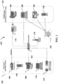
- FIG. 1 is a block diagram showing an example system 100 in which video may be communicated between various video sources 102 and end node devices 122 that consume the video, e.g., by displaying the video on a display to an end user.
- Video sources 102 may include devices that have a camera functionality built into them, such as a video camera 104 that may be directly able to communicate via an IP link, a phone with a built-in camera 106, a desktop computer 108 and a tablet or a laptop computer 110.
- Video sources may also include non-camera sources that still can produce video signals, e.g., a media source 112 with a video to IP convertor.
- the media source 112 maybe, e.g., a network reception device such as a set-top box, or a scanner or a film-to-digital video convertor and so on.
- the video sources 102 may communicate with the end node devices 122 via an IP network that includes IP network equipment such as an Ethernet switch 114, a wireless IP transmitter such as a base station of a cellular system or an access point of a Wi-Fi network and and/or other IP functions that are well known to a person of skill in the art.
- IP network may comprise multiple wired and wireless networks connected to each other.
- end-node devices may be a personal computer 124, a laptop computer 126, a tablet 128, and/or a phone with an image display 130.
- An end-node device 122 may be able to send and receive data, including video data, via an IP interface such as a wired or a wireline IP interface.
- the computational platform on which an end node device 122 operates may include an operating system.
- Many operating systems e.g., various Windows versions by Microsoft, provide native support for being able to receive and transmit video data and control data related to the video data.
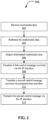
- FIG. 2 is a flowchart for an example method 200 of facilitating exchange of multimedia information between a camera device, e.g., a video source 102, and a user device, e.g., the end-node devices 122.
- the method 200 may be implemented by a bridging device, e.g., the bridging device 116.
- the method 200 includes, at 202, receiving multimedia data via an IP interface.
- the IP interface may be wired or wireless, e.g., using cat5 Ethernet cable, as described in this document.
- the method 200 includes, at 204, transcoding the multimedia data from an IP format to a peripheral bus format.
- the IP format may include compressed digital video in H.264 compression format, which is then transmitted using MPEG-2 transport packets over IP.
- the IP format may include an uncompressed video format, e.g., IETF format specified in RFC 4175, or uncompressed video format specified by the Video Services Forum.
- the peripheral bus format may include the UVC format for carriage of video over USB, which supports the carriage of both compressed and uncompressed video.
- IP formats may include RTP using MPEG-2 compression, H.265 (High efficiency video coding HEVC), VP 8/9 video compression, MPEG-DASH or HLS streaming format, or other suitable format.
- the peripheral bus format may include other peripheral bus formats, such as DisplayPort, HDMI, etc.
- the method 200 includes, at 208, translating, for a first control message received on the IP interface, the first control message to the peripheral bus format.
- the translation may be performed using a look up table (LUT) mechanism.
- the first control message may be, e.g., an ONVIF control message.
- the method 200 includes, at 210, translating, for a second control message received on a peripheral bus interface, the second control message into an IP interface format.
- the translation may be performed using the LUT mechanism.
- the second control message may include a USB UVC control message and the IP interface format may include the ONVIF protocol.
- the method 200 includes, at 212, transmitting the translated second control message via the IP interface.
- the translated second control message may comply with the Open Network Video Interface Forum (ONVIF) format.
- ONVIF Open Network Video Interface Forum
- the transcoding operation may comprise operations as described in the example shown in FIG. 3.
- FIG. 3 is a block diagram showing an example of a video transcoding operation.
- Box 302 represents a decompression operation in which video received on the IP interface may be decompressed.
- the decompression 302 may be performed using code executed on a processor, in the hardware, or using a combination of hardware acceleration and software execution of the decompression operation.
- transcoding info 304 may be extracted. This information may include information, e.g., motion vector data, useful for efficient re-encoding by the video recompression operation 306.
- the recompression operation 306 may produce, e.g., motion Joint Pictures Experts Group (MJPEG) compatible video output from received H.264 video.
- MJPEG motion Joint Pictures Experts Group
- the uncompressed video when uncompressed video is received via the IP interface, the uncompressed video may be transcoded into an compressed video format such as MJPEG.
- the decompression operation 302 may be omitted or alternatively may simply involve packet header removal of received IP packets to extract the video data payload.
- the uncompressed video when uncompressed video is received via the IP interface, the uncompressed video may be left uncompressed when transferring out over the peripheral bus.
- the operations described in FIG. 3 may simply be omitted; instead, video payload from IP packets may be extracted and re-encapsulated into the USB UVC format.
- any well-known video compression and transportation format may be used.
- the video encoding format may be H.264, HVEC/H.265, MJPEG, etc.
- Transportation may be performed using MPEG transport encapsulated within IP packets, RTSP, RTP or .mp4 file format using unicast, multicast or broadcast transmission.
- the conversion of IP video to UVC video can be done in the bridging device or as a software solution operating within applications or drivers within the operating systems of the end nodes or user devices.
- end-nodes 122 can simultaneously see and use multiple video sources, e.g., USB UVC cameras. Similarly, multimedia data from a given camera can be transmitted to multiple end-nodes 122 at the same time. This may be achieved such that the bridging device 116 may receive a single video stream from the source, and may produce multiple outputs on multiple USB UVC connections for multiple end-nodes.
- video sources e.g., USB UVC cameras.
- multimedia data from a given camera can be transmitted to multiple end-nodes 122 at the same time. This may be achieved such that the bridging device 116 may receive a single video stream from the source, and may produce multiple outputs on multiple USB UVC connections for multiple end-nodes.
- embodiments can overcome limitation associated with certain peripheral bus standards that allow for a peripheral device to connect only with a single user device (host) at a time.
- USB devices can be connected to multiple end-nodes simultaneously.
- video distribution can be achieved using low-cost and ubiquitously available Ethernet networking technology for carriage of IP traffic, thereby making it un-necessary to use expensive HDMI or DVI outputs and corresponding distribution amplifiers to distribute video to multiple locations.
- Ethernet distribution allows as many Hosts as Ethernet can support (thousands) to simultaneously connect to the same video source.
- Cat5 or Cat6 cable could be used for Ethernet wiring. Such cables can be built on-site after routing them through walls and conduit, thus making the installation process inexpensive. Individual Ethernet Cat5 and Cat6 cables can operate for distances of 100m without extenders or extra switches.
- the bridging device 116 may present itself as a single video source to a USB Host and it can switch its input to use any source on the Ethernet network at the request of any external controlling device.
- the ONVIF control protocol defined by the Open Network Video Interface Forum, provides a video control and streaming protocol that allows cameras and other video sources to operate in a uniform manner, allowing a controller supporting ONVIF to work with many different video device manufacturers.
- the bridging device 116 could convert control commands in the peripheral bus format to the common ONVIF commands and ONVIF IP video streams to USB UVC video streams.
- the ONVIF has defined a protocol called PTZ (pan tilt zoom) Service Specification. Using this protocol, a camera can be controlled to perform various operations such as zooming in or out, tilting, panning at a specified velocity, queried for its capabilities, and so on.
- the bridging device 116 may implement a look-up-table (LUT) for control command translations as described in operations 208 and 210.
- the LUT may have multiple columns corresponding to multiple peripheral bus protocols, and a column corresponding to the ONVIF protocol. Each row may provide a translation of a given ONVIF command and a corresponding peripheral bus command.
- the bridging device 116 may perform command translation such that a user device may use its own peripheral bus specific protocol for controlling the camera, while camera is always being controlled by a uniform, single control protocol.
- FIG. 4 illustrates an example embodiment of a bridging device 404.
- the bridging device may include an Ethernet interface 406 via which it is able to communicate with the Internet, and in particular IP cameras 402, through a possible Ethernet switch 114.
- the IP camera 402 may implement a camera control API, e.g., ONVIF API for remotely controlling the camera.
- the bridge device 404 may receive video from the IP camera 402 in H.264 or another video format via the Ethernet module 406.
- the Ethernet module 406 may provide control portion of the received IP traffic to a Control and Translation module 410, which may, among other things, perform translation between ONVIF commands and UVC commands.
- the Ethernet module 406 may provide the multimedia portion, which may include video and/or audio data, to a media handling module 408, such as a Gstreamer module that implements RTSP functionality to receive and/or transmit multimedia data.
- the media handling module 408 may extract the received video and provide the extracted video to a transcoding module 412.
- the reformatted multimedia data may be provided to a capture module 414.
- the capture module 414 may be situated within the bridge device 404 such that, at the output of the capture module, the reformatted multimedia data may appear as if it has been captured by a camera plugged into a peripheral of the host device.
- a driver module 416 may be used to communicate with the capture module 414 and the Control and Translation module 410 such that the control data and the multimedia data is passed via the driver module 416, which makes it appear to a host interface module 418 as if the IP camera 402 is locally plugged into the bus.
- the host interface module 418 may correspond to a USB device and the driver module 416 may comprise the USB gadget framework.
- the host interface module 418 may be communicatively connected with a user device via a USB connector and may be using a peripheral bus format such as the UVC 1.1 or UVC 1.5 format.
- FIG. 4 can be operated such that, from the perspective of the applications running on the user device, it may appear that a camera is plugged into the peripheral socket, e.g., USB connector of the user device. It will further be appreciated that most operating systems include support for certain types of peripheral devices. For example, in the embodiment depicted in FIG. 4 , an IP camera that is remotely present in the IP network is able to be communicatively connected with a user device simply by the user device communicating with a bridge device via USB peripheral bus.
- an apparatus for facilitating exchange of multimedia information between a camera device and a user device includes an IP interface communicatively coupling the apparatus to the camera device.
- the apparatus may include a module that receives multimedia data via the IP interface in an internet video format and extracts digital video, either compressed or uncompressed, e.g., by parsing using a software program executed on a processor.
- the apparatus also includes a module that reformats the extracted digital video into a peripheral bus format, e.g., using a LUT mechanism.
- the apparatus includes a module that provides video in the peripheral bus format to the user device, e.g., using a software driver executed on the user device.
- a system for video communication includes a camera apparatus (e.g., 102) coupled to an internet protocol (IP) network, a bridging apparatus (e.g., 116) having a first connection coupled to the IP network and a second connection with a peripheral bus, and a user device (e.g., 122) comprising a memory and a processor, wherein the processor executes an operating system that natively supports video communication over the peripheral bus.
- the bridging apparatus e.g., 116) transcodes video between the IP network and the peripheral bus.
- the camera apparatus is controllable using the ONVIF PTZ protocol.
- data processing apparatus encompasses all apparatus, devices, and machines for processing data, including by way of example a programmable processor, a computer, or multiple processors or computers.
- the apparatus can include, in addition to hardware, code that creates an execution environment for the computer program in question, e.g., code that constitutes processor firmware, a protocol stack, a database management system, an operating system, or a combination of one or more of them.
- a propagated signal is an artificially generated signal, e.g., a machine-generated electrical, optical, or electromagnetic signal, that is generated to encode information for transmission to suitable receiver apparatus.
- a computer program (also known as a program, software, software application, script, or code) can be written in any form of programming language, including compiled or interpreted languages, and it can be deployed in any form, including as a stand alone program or as a module, component, subroutine, or other unit suitable for use in a computing environment.
- a computer program does not necessarily correspond to a file in a file system.
- a program can be stored in a portion of a file that holds other programs or data (e.g., one or more scripts stored in a markup language document), in a single file dedicated to the program in question, or in multiple coordinated files (e.g., files that store one or more modules, sub programs, or portions of code).
- a computer program can be deployed to be executed on one computer or on multiple computers that are located at one site or distributed across multiple sites and interconnected by a communication network.
- the processes and logic flows described in this document can be performed by one or more programmable processors executing one or more computer programs to perform functions by operating on input data and generating output.
- the processes and logic flows can also be performed by, and apparatus can also be implemented as, special purpose logic circuitry, e.g., an FPGA (field programmable gate array) or an ASIC (application specific integrated circuit).
- processors suitable for the execution of a computer program include, by way of example, both general and special purpose microprocessors, and any one or more processors of any kind of digital computer.
- a processor will receive instructions and data from a read only memory or a random access memory or both.
- the essential elements of a computer are a processor for performing instructions and one or more memory devices for storing instructions and data.
- a computer will also include, or be operatively coupled to receive data from or transfer data to, or both, one or more mass storage devices for storing data, e.g., magnetic, magneto optical disks, or optical disks.
- mass storage devices for storing data, e.g., magnetic, magneto optical disks, or optical disks.
- a computer need not have such devices.
- Computer readable media suitable for storing computer program instructions and data include all forms of non volatile memory, media and memory devices, including by way of example semiconductor memory devices, e.g., EPROM, EEPROM, and flash memory devices; magnetic disks, e.g., internal hard disks or removable disks; magneto optical disks; and CD ROM and DVD-ROM disks.
- semiconductor memory devices e.g., EPROM, EEPROM, and flash memory devices
- magnetic disks e.g., internal hard disks or removable disks
- magneto optical disks e.g., CD ROM and DVD-ROM disks.
- the processor and the memory can be supplemented by, or incorporated in, special purpose logic circuitry.
Landscapes
- Engineering & Computer Science (AREA)
- Signal Processing (AREA)
- Multimedia (AREA)
- Computer Networks & Wireless Communication (AREA)
- General Engineering & Computer Science (AREA)
- Theoretical Computer Science (AREA)
- Computer Security & Cryptography (AREA)
- Physics & Mathematics (AREA)
- General Physics & Mathematics (AREA)
- Computing Systems (AREA)
- Automation & Control Theory (AREA)
- Two-Way Televisions, Distribution Of Moving Picture Or The Like (AREA)
Description
- This patent document relates to video communication, and in one aspect, transporting video data to and from a universal serial bus peripheral interface and an internet protocol interface.
- With ever-increasing availability of high speed data networks and user devices that have computational power to process and display video in real time, videoconferencing is fast becoming a tool for both social networking, e.g., a video chat between two users, and also a business productivity tool, e.g., a video conference between multiple users in multiple locations. Video is often captured using a web camera that is connected to a user computer via a peripheral connection such as a Universal Serial Bus (USB) connection.
-
US 2012/315852 describes a system and method for zero client communications. A zero client device includes a housing, and in the housing, a transcoding processing unit (transcoder) and a communications processing unit coupled to the transcoder. The transcoder is configured to receive input data from human interface device(s), encode the input data, and provide the encoded input data to the communications processing unit for transmission over a network to a server. The communications processing unit is configured to receive the encoded input data from the transcoder, transmit the encoded input data over the network to the server, receive output data from the server, and send the output data to the transcoder. The transcoder is further configured to receive the output data from the communications processing unit, decode the output data, and send the decoded output data to at least one of the human interface devices. - The present document discloses techniques for allowing a user device to connect to a video camera via an internet protocol (IP) connection, while still allowing its operating system to use natively available video processing capabilities of a non-IP peripheral bus.
- The invention relates to a system, as further defined in claim 1, for facilitating exchange of multimedia information between two camera devices and a user device.
- These and other aspects, and their implementations and variations are set forth in the drawings, the description and the claims.
-
-
FIG. 1 is a block diagram of an example of an IP video communication system. -
FIG. 2 is a block diagram depiction of an example software protocol stack implementation in a user device. -
FIG. 3 is a block diagram of an example video transcoding implementation. -
FIG. 4 is a block diagram of an example bridging apparatus. - Today's computer operating systems natively support video camera using peripheral bus connections. For example, users often use external camera devices, e.g., webcams, for capturing video and/or audio and use them with software applications running on user devices. Many modem operating systems natively support camera functionalities along with device drivers for certain communication peripherals. The "native" support could mean, e.g., that a user need not install proprietary camera software drivers on their devices, and could simply plug a camera into the peripheral connection, wait for the operating system to recognize the camera and begin to use the camera in a matter of a few seconds.
- One such example of natively supported camera functionality is the Universal Serial Bus (USB) interface commonly found in modern personal computers, tablets, laptops, and so on. Operating systems, such as various Windows versions by Microsoft, include video camera functionality with a native USB driver, thus providing a "plug-and-play" user experience for a USB-connected camera, without having to load camera-specific device drivers or any other new software.
- Wireless implementations of USB connectivity are commercially available, but such products are not universally available, and often require users to install additional software to make the wireless functionality work. Thus, USB often limits connectivity between a user device and a camera device to a USB cable. The need for a wired connection thus limits the distance between the user device and the camera device to typical lengths of USB connectors, or up to about 10 meters or so. Furthermore, peripheral bus connection protocols such as USB are often point-to-point connections, meaning that only a single user device may be able to connect to and control a USB camera. A similar problem exits with other wired video transmission standards such as an High Definition Multimedia Interface (HDMI) connector or a Digital Visual Interface (DVI) cable connector.
- Such limitations of a peripheral camera device limit the usefulness in many practical applications. For example, to access a USB camera in a conference room, multiple user may have to have their own, possibly long, USB cables plugged into an N:1 USB multiplexer that then provides a one-at-a-time access to users. Furthermore, USB user devices, or hosts, can connect to multiple video sources using USB, but the USB standard does not allow an external controller to tell the USB Host which video source to use at any given time. One solution may be that conference rooms are pre-wired with USB or HDMI or DVI or some other suitable cables such that multiple locations are available throughout the room to allow users to plug in their devices to cameras in the room. However, routing prefabricated cables with attached connectors through walls and conduit is difficult or impossible and often may cause destructive degradation in the quality of connection. Such installations may also need repeaters to stretch out over long lengths of connections, which is an expensive solution. To add to this, not all commercially available USB cable extenders support all USB webcams, making the process of selecting a correct cable difficult.
-
US Pat. Pub. No. 20090231485 to Stienke et al. discloses techniques for connecting a mobile device to an external display. In particular, a dongle that carriers video data over USB (encoded using UVC) protocol is disclosed to connect low resolution display on the mobile device side with a high resolution external display. The dongle performs resolution reduction from high resolution to low resolution. -
US Patent 8,451,910 to Lohier et al. discloses operation of a wireless webcam that transmits video data in USB UVC format over a wireless Wi-Fi interface. The encoding of video is adapted to maintain isochronous nature of UVC video over the wireless interface. -
US Pat. Pub. No. 20080147928 to Nicolet et al. discloses techniques for connecting a device to a host via multiple bus interfaces, such as USB UVC and wireless, such that the bus interface can be seamlessly switched during operation. The relationship between multiple busses of a single external device is tracked by maintaining a single Physical Device Object (PDO) for each device. -
US Patent 8,019,917 to Chen et al. discloses an audio/video capture device that uses USB UVC protocol for transmitting audio video data to a host. In particular, the UVC protocol is modified to support multiple isochronous flows on the same USB connection. Video conferencing is specifically mentioned as an example application of the technology. - The prior art, however, fails to provide satisfactory solutions for some of the operational problems described herein.
- The techniques described in the present document can be used to overcome these operational limitations, and others. In some embodiments, the disclosed technology can be used for conversion of IP network video streams to the USB Video Class protocol (USB UVC) and vice versa. In another advantageous aspect, the disclosed technology may be implemented in a bridging device that is external to the user device, or may be integrated to operate within the hardware platform of the user device, e.g., by an all-software or a combined hardware-software embodiment. These, and other, aspects are described in greater detail throughout this document.
-
FIG. 1 is a block diagram showing anexample system 100 in which video may be communicated betweenvarious video sources 102 andend node devices 122 that consume the video, e.g., by displaying the video on a display to an end user.Video sources 102 may include devices that have a camera functionality built into them, such as avideo camera 104 that may be directly able to communicate via an IP link, a phone with a built-incamera 106, adesktop computer 108 and a tablet or alaptop computer 110. Video sources may also include non-camera sources that still can produce video signals, e.g., amedia source 112 with a video to IP convertor. Themedia source 112 maybe, e.g., a network reception device such as a set-top box, or a scanner or a film-to-digital video convertor and so on. - The
video sources 102 may communicate with theend node devices 122 via an IP network that includes IP network equipment such as anEthernet switch 114, a wireless IP transmitter such as a base station of a cellular system or an access point of a Wi-Fi network and and/or other IP functions that are well known to a person of skill in the art. In general, the IP network may comprise multiple wired and wireless networks connected to each other. - By way of example, and not exhaustively, end-node devices may be a
personal computer 124, alaptop computer 126, atablet 128, and/or a phone with animage display 130. An end-node device 122 may be able to send and receive data, including video data, via an IP interface such as a wired or a wireline IP interface. - The computational platform on which an
end node device 122 operates may include an operating system. Many operating systems, e.g., various Windows versions by Microsoft, provide native support for being able to receive and transmit video data and control data related to the video data. -
FIG. 2 is a flowchart for anexample method 200 of facilitating exchange of multimedia information between a camera device, e.g., avideo source 102, and a user device, e.g., the end-node devices 122. Themethod 200 may be implemented by a bridging device, e.g., thebridging device 116. - The
method 200 includes, at 202, receiving multimedia data via an IP interface. In various embodiments, the IP interface may be wired or wireless, e.g., using cat5 Ethernet cable, as described in this document. - The
method 200 includes, at 204, transcoding the multimedia data from an IP format to a peripheral bus format. For example, in some embodiments, the IP format may include compressed digital video in H.264 compression format, which is then transmitted using MPEG-2 transport packets over IP. In some embodiments, the IP format may include an uncompressed video format, e.g., IETF format specified in RFC 4175, or uncompressed video format specified by the Video Services Forum. In some embodiments, the peripheral bus format may include the UVC format for carriage of video over USB, which supports the carriage of both compressed and uncompressed video. Other examples of IP formats may include RTP using MPEG-2 compression, H.265 (High efficiency video coding HEVC), VP 8/9 video compression, MPEG-DASH or HLS streaming format, or other suitable format. The peripheral bus format may include other peripheral bus formats, such as DisplayPort, HDMI, etc. - The
method 200 includes, at 206, outputting the reformatted multimedia data on a peripheral bus. One such example of a suitable peripheral bus includes USB, which is natively supported by the operating system of the user device receiving the video data. Native support may be provided, e.g., by bundling software used for operation of the peripheral bus with the installation of the operating system. The software may include, e.g., a driver software that detects plugging/unplugging of external devices to the peripheral bus and receiving and transmitting data over the peripheral bus. - The
method 200 includes, at 208, translating, for a first control message received on the IP interface, the first control message to the peripheral bus format. The translation may be performed using a look up table (LUT) mechanism. The first control message may be, e.g., an ONVIF control message. - The
method 200 includes, at 210, translating, for a second control message received on a peripheral bus interface, the second control message into an IP interface format. The translation may be performed using the LUT mechanism. In some embodiments, the second control message may include a USB UVC control message and the IP interface format may include the ONVIF protocol. - The
method 200 includes, at 212, transmitting the translated second control message via the IP interface. For example, the translated second control message may comply with the Open Network Video Interface Forum (ONVIF) format. - In some embodiments, the transcoding operation may comprise operations as described in the example shown in
FIG. 3. FIG. 3 is a block diagram showing an example of a video transcoding operation.Box 302 represents a decompression operation in which video received on the IP interface may be decompressed. Thedecompression 302 may be performed using code executed on a processor, in the hardware, or using a combination of hardware acceleration and software execution of the decompression operation. During this operation, transcodinginfo 304 may be extracted. This information may include information, e.g., motion vector data, useful for efficient re-encoding by thevideo recompression operation 306. Other information extracted for transcoding may include command and control information, and information that is often included in the user data fields of formats such as H.264, which is useful for an application presenting the information to a user. Such information may include caption data, color space definition, and so on. The information is provided to theformat encapsulation stage 308 in which the output of thevideo recompression operation 306 is formatted to comply with encoded video format of the peripheral bus on which the transcoded video is sent to theuser device 122. - The
recompression operation 306 may produce, e.g., motion Joint Pictures Experts Group (MJPEG) compatible video output from received H.264 video. In some embodiments, when uncompressed video is received via the IP interface, the uncompressed video may be transcoded into an compressed video format such as MJPEG. In such embodiments, thedecompression operation 302 may be omitted or alternatively may simply involve packet header removal of received IP packets to extract the video data payload. In some embodiments, when uncompressed video is received via the IP interface, the uncompressed video may be left uncompressed when transferring out over the peripheral bus. In such embodiments, the operations described inFIG. 3 may simply be omitted; instead, video payload from IP packets may be extracted and re-encapsulated into the USB UVC format. - On the IP network side, any well-known video compression and transportation format may be used. The video encoding format may be H.264, HVEC/H.265, MJPEG, etc. Transportation may be performed using MPEG transport encapsulated within IP packets, RTSP, RTP or .mp4 file format using unicast, multicast or broadcast transmission.
- In some embodiments, the conversion of IP video to UVC video can be done in the bridging device or as a software solution operating within applications or drivers within the operating systems of the end nodes or user devices.
- In one advantageous aspect, because the IP network allows for communication to/from multiple cameras, and because the bridge device is able to monitor and translate control data, end-
nodes 122 can simultaneously see and use multiple video sources, e.g., USB UVC cameras. Similarly, multimedia data from a given camera can be transmitted to multiple end-nodes 122 at the same time. This may be achieved such that thebridging device 116 may receive a single video stream from the source, and may produce multiple outputs on multiple USB UVC connections for multiple end-nodes. - In one advantageous aspect, embodiments can overcome limitation associated with certain peripheral bus standards that allow for a peripheral device to connect only with a single user device (host) at a time. Using the disclosed techniques, USB devices can be connected to multiple end-nodes simultaneously.
- In another advantageous aspect, video distribution can be achieved using low-cost and ubiquitously available Ethernet networking technology for carriage of IP traffic, thereby making it un-necessary to use expensive HDMI or DVI outputs and corresponding distribution amplifiers to distribute video to multiple locations. Ethernet distribution allows as many Hosts as Ethernet can support (thousands) to simultaneously connect to the same video source. Cat5 or Cat6 cable could be used for Ethernet wiring. Such cables can be built on-site after routing them through walls and conduit, thus making the installation process inexpensive. Individual Ethernet Cat5 and Cat6 cables can operate for distances of 100m without extenders or extra switches.
- Furthermore, allowing multiple users to simultaneously access and control the video stream and to also support multiple access locations opens up the possibility of additional application-layer features that are not offered by present-day videoconferencing applications.
- In some embodiments, the
bridging device 116 may present itself as a single video source to a USB Host and it can switch its input to use any source on the Ethernet network at the request of any external controlling device. - Historically, IP camera and IP streaming vendors used proprietary control protocols, which makes it difficult for any given user device to operate with multiple cameras, either simultaneously or at different times, without performing cumbersome software installations.
- The ONVIF control protocol, defined by the Open Network Video Interface Forum, provides a video control and streaming protocol that allows cameras and other video sources to operate in a uniform manner, allowing a controller supporting ONVIF to work with many different video device manufacturers. Advantageously, the
bridging device 116 could convert control commands in the peripheral bus format to the common ONVIF commands and ONVIF IP video streams to USB UVC video streams. - For example, the ONVIF has defined a protocol called PTZ (pan tilt zoom) Service Specification. Using this protocol, a camera can be controlled to perform various operations such as zooming in or out, tilting, panning at a specified velocity, queried for its capabilities, and so on. The
bridging device 116 may implement a look-up-table (LUT) for control command translations as described inoperations 208 and 210. The LUT may have multiple columns corresponding to multiple peripheral bus protocols, and a column corresponding to the ONVIF protocol. Each row may provide a translation of a given ONVIF command and a corresponding peripheral bus command. Using the command translation LUT, thebridging device 116 may perform command translation such that a user device may use its own peripheral bus specific protocol for controlling the camera, while camera is always being controlled by a uniform, single control protocol. - In some embodiments, the
method 200 may also include handling of audio data. The multimedia data may be video only, audio and video, or audio only depending on how users have set up their conference sessions. In some embodiments, the audio may be received using a microphone that is co-located with the camera (e.g., near the camera lens). Alternatively, audio may be received and digitized using a microphone that is nearby a user, e.g., a built-in audio capture function of the user device. Because audio processing often experiences delays that are significantly shorter than the corresponding video processing delays (e.g., 10 to 20 milliseconds instead of 1 to 2 seconds for video), thebridging device 116 may include a buffer for storing audio temporarily for lip synchronization or alignment with the corresponding video. In some embodiments, a user interface control may be provided on the bridging device, or on the application running on a user device that is using the multimedia data, to enable user control of lip synchronization delay adjustment. -
FIG. 4 illustrates an example embodiment of abridging device 404. The bridging device may include anEthernet interface 406 via which it is able to communicate with the Internet, and inparticular IP cameras 402, through apossible Ethernet switch 114. TheIP camera 402 may implement a camera control API, e.g., ONVIF API for remotely controlling the camera. Thebridge device 404 may receive video from theIP camera 402 in H.264 or another video format via theEthernet module 406. TheEthernet module 406 may provide control portion of the received IP traffic to a Control andTranslation module 410, which may, among other things, perform translation between ONVIF commands and UVC commands. - The
Ethernet module 406 may provide the multimedia portion, which may include video and/or audio data, to a media handling module 408, such as a Gstreamer module that implements RTSP functionality to receive and/or transmit multimedia data. The media handling module 408 may extract the received video and provide the extracted video to atranscoding module 412. The reformatted multimedia data may be provided to acapture module 414. Thecapture module 414 may be situated within thebridge device 404 such that, at the output of the capture module, the reformatted multimedia data may appear as if it has been captured by a camera plugged into a peripheral of the host device. - The
transcoding module 412 may reformat the multimedia data to conform to the peripheral bus standard at its output. Thetranscoding module 412 may also perform any other control functions such as bitrate change, resolution change, color space rotation, gamma correction, etc., should under the control of the Control andTranslation module 410. - A
driver module 416 may be used to communicate with thecapture module 414 and the Control andTranslation module 410 such that the control data and the multimedia data is passed via thedriver module 416, which makes it appear to ahost interface module 418 as if theIP camera 402 is locally plugged into the bus. For example, thehost interface module 418 may correspond to a USB device and thedriver module 416 may comprise the USB gadget framework. Thehost interface module 418 may be communicatively connected with a user device via a USB connector and may be using a peripheral bus format such as the UVC 1.1 or UVC 1.5 format. - It will be appreciated that the embodiment depicted in
FIG. 4 can be operated such that, from the perspective of the applications running on the user device, it may appear that a camera is plugged into the peripheral socket, e.g., USB connector of the user device. It will further be appreciated that most operating systems include support for certain types of peripheral devices. For example, in the embodiment depicted inFIG. 4 , an IP camera that is remotely present in the IP network is able to be communicatively connected with a user device simply by the user device communicating with a bridge device via USB peripheral bus. - In some example embodiments, an apparatus for facilitating exchange of multimedia information between a camera device and a user device includes an IP interface communicatively coupling the apparatus to the camera device. The apparatus may include a module that receives multimedia data via the IP interface in an internet video format and extracts digital video, either compressed or uncompressed, e.g., by parsing using a software program executed on a processor. The apparatus also includes a module that reformats the extracted digital video into a peripheral bus format, e.g., using a LUT mechanism. The apparatus includes a module that provides video in the peripheral bus format to the user device, e.g., using a software driver executed on the user device. The apparatus includes a module that, for a first command received from the user device in the peripheral bus format, translates the first command into an internet format, and for a second command received from the IP interface in the internet format, translates the second command into the peripheral bus format. The apparatus also includes a module that operates to provide connectivity between the user device and the camera device. The translation may be performed using the LUT mechanism.
- In some embodiments, a system for video communication includes a camera apparatus (e.g., 102) coupled to an internet protocol (IP) network, a bridging apparatus (e.g., 116) having a first connection coupled to the IP network and a second connection with a peripheral bus, and a user device (e.g., 122) comprising a memory and a processor, wherein the processor executes an operating system that natively supports video communication over the peripheral bus. The bridging apparatus (e.g., 116) transcodes video between the IP network and the peripheral bus. The camera apparatus is controllable using the ONVIF PTZ protocol.
- The disclosed and other embodiments and the functional operations and modules described in this document can be implemented in digital electronic circuitry, or in computer software, firmware, or hardware, including the structures disclosed in this document and their structural equivalents, or in combinations of one or more of them. The disclosed and other embodiments can be implemented as one or more computer program products, i.e., one or more modules of computer program instructions encoded on a computer readable medium for execution by, or to control the operation of, data processing apparatus. The computer readable medium can be a machine-readable storage device, a machine-readable storage substrate, a memory device, a composition of matter effecting a machine-readable propagated signal, or a combination of one or more them. The term "data processing apparatus" encompasses all apparatus, devices, and machines for processing data, including by way of example a programmable processor, a computer, or multiple processors or computers. The apparatus can include, in addition to hardware, code that creates an execution environment for the computer program in question, e.g., code that constitutes processor firmware, a protocol stack, a database management system, an operating system, or a combination of one or more of them. A propagated signal is an artificially generated signal, e.g., a machine-generated electrical, optical, or electromagnetic signal, that is generated to encode information for transmission to suitable receiver apparatus.
- A computer program (also known as a program, software, software application, script, or code) can be written in any form of programming language, including compiled or interpreted languages, and it can be deployed in any form, including as a stand alone program or as a module, component, subroutine, or other unit suitable for use in a computing environment. A computer program does not necessarily correspond to a file in a file system. A program can be stored in a portion of a file that holds other programs or data (e.g., one or more scripts stored in a markup language document), in a single file dedicated to the program in question, or in multiple coordinated files (e.g., files that store one or more modules, sub programs, or portions of code). A computer program can be deployed to be executed on one computer or on multiple computers that are located at one site or distributed across multiple sites and interconnected by a communication network.
- The processes and logic flows described in this document can be performed by one or more programmable processors executing one or more computer programs to perform functions by operating on input data and generating output. The processes and logic flows can also be performed by, and apparatus can also be implemented as, special purpose logic circuitry, e.g., an FPGA (field programmable gate array) or an ASIC (application specific integrated circuit).
- Processors suitable for the execution of a computer program include, by way of example, both general and special purpose microprocessors, and any one or more processors of any kind of digital computer. Generally, a processor will receive instructions and data from a read only memory or a random access memory or both. The essential elements of a computer are a processor for performing instructions and one or more memory devices for storing instructions and data. Generally, a computer will also include, or be operatively coupled to receive data from or transfer data to, or both, one or more mass storage devices for storing data, e.g., magnetic, magneto optical disks, or optical disks. However, a computer need not have such devices. Computer readable media suitable for storing computer program instructions and data include all forms of non volatile memory, media and memory devices, including by way of example semiconductor memory devices, e.g., EPROM, EEPROM, and flash memory devices; magnetic disks, e.g., internal hard disks or removable disks; magneto optical disks; and CD ROM and DVD-ROM disks. The processor and the memory can be supplemented by, or incorporated in, special purpose logic circuitry.
- While this document contains many specifics, these should not be construed as limitations on the scope of an invention that is claimed or of what may be claimed, but rather as descriptions of features specific to particular embodiments. Certain features that are described in this document in the context of separate embodiments can also be implemented in combination in a single embodiment. Conversely, various features that are described in the context of a single embodiment can also be implemented in multiple embodiments separately or in any suitable sub-combination. Moreover, although features may be described above as acting in certain combinations and even initially claimed as such, one or more features from a claimed combination can in some cases be excised from the combination, and the claimed combination may be directed to a sub-combination or a variation of a sub-combination. Similarly, while operations are depicted in the drawings in a particular order, this should not be understood as requiring that such operations be performed in the particular order shown or in sequential order, or that all illustrated operations be performed, to achieve desirable results.
- Only a few examples and implementations are disclosed. The invention is solely defined by the appended claims.
Claims (11)
- A system, comprising:first and second camera apparatuses (102) coupled to an internet protocol, IP, network;a bridging apparatus (116) having a first connection coupled to the IP network and a second connection with a peripheral bus; anda user device (122) comprising a memory and a processor, wherein the processor is configured to execute an operating system that natively supports video communication over the peripheral bus; andwherein the bridging apparatus (116) is configured to transcode video data between the IP network and the peripheral bus, wherein the user device (122) is configured to use its own peripheral bus protocol to access and control the first and second camera apparatuses (102), and wherein the bridging apparatus (116) is further configured to transcode control signals from the user device to a uniform, single control protocol for the first and second camera apparatuses (102) to allow the user device (122) to simultaneously access and control video streams provided by the first and second camera apparatuses (102).
- The system of claim 1, wherein the first and second camera apparatuses (102) are controllable using an Open Network Video Interface Forum, ONVIF, pan-tilt-zoom, PTZ, protocol.
- The system of claim 1, wherein the transcoding by the bridging apparatus (116) comprises looking up a look-up table, LUT, (LUT) for translation of a control message.
- The system of claim 1, wherein the bridging apparatus (116) is configuredto transcode multimedia data that includes audio data and the video data, and wherein the bridging apparatus (116) includes a buffer for temporarily storing the audio data for alignment with video data.
- The system of claim 1, wherein the user device (122) further comprises a display for displaying the video streams provided by one or both of the first and second camera apparatuses (102).
- The system of claim 5, further comprising a second user (122) device that includes a second display configured to display the video streams, wherein the second user device (122)is configured to use its own peripheral bus protocol to access and control the first and second camera apparatuses (102), wherein the bridging apparatus (116) is further configured to transcode control signals from the second user device to the uniform, single control protocol for the first and second camera apparatuses (102) to allow the second user device (122) to simultaneously access and control the video streams provided by the first and second camera apparatuses (102), and wherein the second user device (122) displays a different configuration of the video streams provided by the first and second camera apparatuses than the first user device.
- The system of claim 1, wherein:At least the first camera apparatus (102) is configured to provide multimedia data that includes the video data;the system further comprises a second user device (122) that comprises an output for outputting the multimedia data;the first user device further comprises an output for outputting the multimedia data; andthe bridging apparatus is configured to transmit the multimedia data to the first and second user devices at the same time.
- The system of claim 1, wherein the peripheral bus is a universal serial bus, USB.
- The system of claim 1, further comprising a second user device (122) thatincludes a second display for displaying the video streams, wherein the second user device (122) is configured to use its own peripheral bus protocol to access and control the first and second camera apparatuses (102), wherein the bridging apparatus (116) is further configured to transcode control signals from the second user device to the uniform, single control protocol for the first and second camera apparatuses (102) to allow the second user device (122) to simultaneously access and control the video streams provided by the first and second camera apparatuses (102), and wherein the second user device (102) displays a different configuration of the video streams provided by the first and second camera apparatuses (102) than the first user device.
- The system of claim 1 wherein the user device (112) is a phone, a laptop computer, or a tablet.
- The system of claim 1 wherein at least the first camera apparatus (102) is a video camera, a phone with a built-in camera, a laptop computer, or a tablet.
Applications Claiming Priority (3)
| Application Number | Priority Date | Filing Date | Title |
|---|---|---|---|
| US15/007,080 US9973638B2 (en) | 2016-01-26 | 2016-01-26 | Peripheral bus video communication using internet protocol |
| PCT/US2016/062024 WO2017131842A1 (en) | 2016-01-26 | 2016-11-15 | Peripheral bus video communication using internet protocol |
| EP16809581.8A EP3408986B1 (en) | 2016-01-26 | 2016-11-15 | Peripheral bus video communication using internet protocol |
Related Parent Applications (1)
| Application Number | Title | Priority Date | Filing Date |
|---|---|---|---|
| EP16809581.8A Division EP3408986B1 (en) | 2016-01-26 | 2016-11-15 | Peripheral bus video communication using internet protocol |
Publications (2)
| Publication Number | Publication Date |
|---|---|
| EP4064715A1 EP4064715A1 (en) | 2022-09-28 |
| EP4064715B1 true EP4064715B1 (en) | 2025-01-01 |
Family
ID=57539613
Family Applications (2)
| Application Number | Title | Priority Date | Filing Date |
|---|---|---|---|
| EP22173389.2A Active EP4064715B1 (en) | 2016-01-26 | 2016-11-15 | Peripheral bus video communication using internet protocol |
| EP16809581.8A Active EP3408986B1 (en) | 2016-01-26 | 2016-11-15 | Peripheral bus video communication using internet protocol |
Family Applications After (1)
| Application Number | Title | Priority Date | Filing Date |
|---|---|---|---|
| EP16809581.8A Active EP3408986B1 (en) | 2016-01-26 | 2016-11-15 | Peripheral bus video communication using internet protocol |
Country Status (5)
| Country | Link |
|---|---|
| US (4) | US9973638B2 (en) |
| EP (2) | EP4064715B1 (en) |
| CN (2) | CN108476220B (en) |
| CA (1) | CA3009172C (en) |
| WO (1) | WO2017131842A1 (en) |
Families Citing this family (21)
| Publication number | Priority date | Publication date | Assignee | Title |
|---|---|---|---|---|
| US9973638B2 (en) * | 2016-01-26 | 2018-05-15 | Qsc, Llc | Peripheral bus video communication using internet protocol |
| US11775952B2 (en) * | 2017-02-28 | 2023-10-03 | Ncr Corporation | Multi-camera simultaneous imaging for multiple processes |
| CN108200387A (en) * | 2017-12-26 | 2018-06-22 | 深圳进化动力数码科技有限公司 | A kind of transmission method of file, system and camera |
| CN118116572A (en) * | 2018-05-18 | 2024-05-31 | 科林达斯公司 | Remote communication and control systems for robotic interventional procedures |
| US11190568B2 (en) | 2019-01-09 | 2021-11-30 | Bose Corporation | Multimedia communication encoding system |
| CN109862322B (en) * | 2019-02-19 | 2020-12-08 | 深圳市研诺达科技有限公司 | A 4G audio and video acquisition device based on UVC data transmission |
| US20200303084A1 (en) * | 2019-03-19 | 2020-09-24 | Westinghouse Electric Company Llc | Radiation tolerant underwater camera with high definition viewing and recording capability |
| CN110113305A (en) * | 2019-03-25 | 2019-08-09 | 视联动力信息技术股份有限公司 | A kind of processing method and system regarding networking service |
| CN114731339B (en) * | 2020-02-18 | 2024-01-30 | 华为技术有限公司 | Information transmission methods and related equipment |
| CN111447401A (en) * | 2020-05-19 | 2020-07-24 | 株洲华通科技有限责任公司 | A video conference system and its working method |
| US11962859B2 (en) * | 2020-06-30 | 2024-04-16 | e-con Systems India Private Limited | System and method for implementation of region of interest based streaming |
| CN111866131A (en) * | 2020-07-20 | 2020-10-30 | 厦门亿联网络技术股份有限公司 | Wireless auxiliary stream data processing method and system based on network protocol stack |
| CN114079744B (en) * | 2020-08-18 | 2024-10-18 | 茂傑国际股份有限公司 | Video and audio transmission device |
| TWI776211B (en) * | 2020-08-18 | 2022-09-01 | 茂傑國際股份有限公司 | Device for transmitting video and audio |
| CN114339112B (en) * | 2020-09-30 | 2023-10-20 | 华为终端有限公司 | Video calling method, electronic device and system |
| CA3096312C (en) | 2020-10-19 | 2021-12-28 | Light Wave Technology Inc. | System for tracking a user during a videotelephony session and method ofuse thereof |
| WO2022104638A1 (en) * | 2020-11-19 | 2022-05-27 | 深圳市大疆创新科技有限公司 | Image transmission data processing method, image transmission device, terminal device, and storage medium |
| CN114650385A (en) * | 2020-12-17 | 2022-06-21 | 深圳Tcl数字技术有限公司 | Control method and device of IP camera, storage medium and smart television |
| CN114745542B (en) * | 2021-01-08 | 2025-10-31 | 华为技术有限公司 | Encoding method, electronic device, communication system, storage medium, and program product |
| US12440294B2 (en) | 2021-10-25 | 2025-10-14 | Siemens Healthineers Endovascular Robotics, Inc. | Medical device systems, methods and computer-readable mediums for operating the same |
| WO2025221688A1 (en) * | 2024-04-15 | 2025-10-23 | Qsc, Llc | Virtualized hardware bridging system and related methods |
Family Cites Families (40)
| Publication number | Priority date | Publication date | Assignee | Title |
|---|---|---|---|---|
| US20020057207A1 (en) * | 1998-04-24 | 2002-05-16 | William J. Sgambati | Control interface for audio video components |
| US7162554B1 (en) * | 2001-07-11 | 2007-01-09 | Advanced Micro Devices, Inc. | Method and apparatus for configuring a peripheral bus |
| US20040041902A1 (en) | 2002-04-11 | 2004-03-04 | Polycom, Inc. | Portable videoconferencing system |
| US7506057B2 (en) * | 2005-06-17 | 2009-03-17 | Fotonation Vision Limited | Method for establishing a paired connection between media devices |
| US7543327B1 (en) * | 2003-11-21 | 2009-06-02 | Arecont Vision Llc | Video surveillance system based on high resolution network cameras capable of concurrent transmission of multiple image formats at video rates |
| US20050239445A1 (en) * | 2004-04-16 | 2005-10-27 | Jeyhan Karaoguz | Method and system for providing registration, authentication and access via broadband access gateway |
| US7644211B2 (en) * | 2004-12-07 | 2010-01-05 | Cisco Technology, Inc. | Method and system for controlling transmission of USB messages over a data network between a USB device and a plurality of host computers |
| US8504707B2 (en) * | 2004-12-07 | 2013-08-06 | Cisco Technology, Inc. | Method and system for sending and receiving USB messages over a data network |
| CN100442858C (en) * | 2005-10-11 | 2008-12-10 | 华为技术有限公司 | Lip synchronization method and device for multimedia real-time transmission in packet network |
| US8553882B2 (en) * | 2006-03-16 | 2013-10-08 | Time Warner Cable Enterprises Llc | Methods and apparatus for connecting a cable network to other network and/or devices |
| US8451910B1 (en) | 2006-07-13 | 2013-05-28 | Logitech Europe S.A. | Wireless multimedia device with real time adjustment of packet retry function and bit rate modulation |
| KR101005094B1 (en) | 2006-09-06 | 2010-12-30 | 노키아 코포레이션 | Mobile terminal devices, dongle and external display devices with enhanced video display interface |
| US20080147928A1 (en) | 2006-10-05 | 2008-06-19 | Richard Nicolet | Transparent support of multiple bus interfaces on a device |
| US20080205417A1 (en) * | 2007-02-26 | 2008-08-28 | Huamin Li | Method and apparatus for bridging wired and wireless communication networks |
| US9544563B1 (en) * | 2007-03-23 | 2017-01-10 | Proximex Corporation | Multi-video navigation system |
| CN101287076A (en) * | 2007-05-30 | 2008-10-15 | 盛乐信息技术(上海)有限公司 | Method and system for interactive entertainment by connecting television and computer through IP network |
| AU2008202703B2 (en) * | 2007-06-20 | 2012-03-08 | Mcomms Design Pty Ltd | Apparatus and method for providing multimedia content |
| WO2009080589A2 (en) * | 2007-12-19 | 2009-07-02 | Telefonaktiebolaget L M Ericsson (Publ) | Communication interface solution |
| EP2099199A1 (en) * | 2008-03-06 | 2009-09-09 | Fifthplay NV | Plug-and-play coupling of sensors to an embedded device |
| JP2009260818A (en) | 2008-04-18 | 2009-11-05 | Nec Corp | Server apparatus, content distribution method, and program |
| TWI381737B (en) | 2009-01-20 | 2013-01-01 | Quanta Comp Inc | Digital video/audio capture device and method thereof |
| TWI482044B (en) * | 2009-07-14 | 2015-04-21 | Wistron Corp | Computer device and ip camera power control method for preventing unauthorized use of a picture-taking function |
| US8508573B2 (en) | 2009-10-27 | 2013-08-13 | Intaglio, Llc | Communication system |
| US20110302334A1 (en) * | 2010-06-07 | 2011-12-08 | Lakshmi Kantha Reddy Ponnatota | Flow Control in Real-Time Transmission of Non-Uniform Data Rate Encoded Video Over a Universal Serial Bus |
| US9116821B2 (en) * | 2011-03-23 | 2015-08-25 | Avocent Corporation | Method and system for USB device virtualization |
| KR101805427B1 (en) * | 2011-04-19 | 2017-12-08 | 삼성전자주식회사 | Device for outputting reservation recorded broadcast and method for controlling thereof |
| US9134945B2 (en) | 2011-06-07 | 2015-09-15 | Clearcube Technology, Inc. | Zero client device with integrated serial bandwidth augmentation and support for out-of-band serial communications |
| CN103124446A (en) * | 2011-11-18 | 2013-05-29 | 中兴通讯股份有限公司 | Wireless broadband data card supporting third-generation (3G) and wireless fidelity (Wi-Fi) network access mode |
| JP5970897B2 (en) * | 2012-03-24 | 2016-08-17 | 日本電気株式会社 | Information processing system, information processing method, portable terminal, server, control method thereof, and control program |
| CN102654766A (en) * | 2012-04-18 | 2012-09-05 | 华中科技大学 | Wireless remote PLC (Programmable Logic Controller) monitoring system and application thereof |
| CN103457806A (en) * | 2012-05-29 | 2013-12-18 | 中兴通讯股份有限公司 | Converter, control system and control method |
| US9838651B2 (en) * | 2012-08-10 | 2017-12-05 | Logitech Europe S.A. | Wireless video camera and connection methods including multiple video or audio streams |
| US10122963B2 (en) | 2013-06-11 | 2018-11-06 | Milestone Av Technologies Llc | Bidirectional audio/video: system and method for opportunistic scheduling and transmission |
| CN110620893A (en) * | 2013-08-29 | 2019-12-27 | Vid拓展公司 | First wireless transmit/receive unit (WTRU) and method executed by the first WTRU |
| CN103823771B (en) * | 2014-03-04 | 2017-02-08 | 飞天诚信科技股份有限公司 | Remote communication method and remote communication system |
| CN104091429A (en) * | 2014-06-27 | 2014-10-08 | 国家电网公司 | Online temperature measurement system for wireless transmission mode of power equipment |
| MY177317A (en) * | 2014-10-16 | 2020-09-11 | Epicamera Sdn Bhd | An electronic platform |
| CN204334852U (en) * | 2015-01-21 | 2015-05-13 | 广东省广播电视网络股份有限公司 | A broadcast HDTV access device based on USB video transmission |
| US10097795B2 (en) * | 2015-10-01 | 2018-10-09 | Sensormatic Electronics, LLC | Network video recorder cluster and method of operation |
| US9973638B2 (en) * | 2016-01-26 | 2018-05-15 | Qsc, Llc | Peripheral bus video communication using internet protocol |
-
2016
- 2016-01-26 US US15/007,080 patent/US9973638B2/en active Active
- 2016-11-15 EP EP22173389.2A patent/EP4064715B1/en active Active
- 2016-11-15 EP EP16809581.8A patent/EP3408986B1/en active Active
- 2016-11-15 CA CA3009172A patent/CA3009172C/en active Active
- 2016-11-15 CN CN201680079460.5A patent/CN108476220B/en active Active
- 2016-11-15 CN CN202010079353.0A patent/CN111212258B/en active Active
- 2016-11-15 WO PCT/US2016/062024 patent/WO2017131842A1/en not_active Ceased
-
2018
- 2018-05-09 US US15/975,144 patent/US10791229B2/en active Active
-
2020
- 2020-07-28 US US16/941,410 patent/US11601557B2/en active Active
-
2023
- 2023-02-16 US US18/170,391 patent/US12592997B2/en active Active
Also Published As
| Publication number | Publication date |
|---|---|
| EP4064715A1 (en) | 2022-09-28 |
| US9973638B2 (en) | 2018-05-15 |
| US11601557B2 (en) | 2023-03-07 |
| US12592997B2 (en) | 2026-03-31 |
| US20230308554A1 (en) | 2023-09-28 |
| US20170214807A1 (en) | 2017-07-27 |
| CA3009172C (en) | 2019-01-22 |
| CN111212258A (en) | 2020-05-29 |
| US10791229B2 (en) | 2020-09-29 |
| WO2017131842A1 (en) | 2017-08-03 |
| CN108476220B (en) | 2020-02-07 |
| EP3408986A1 (en) | 2018-12-05 |
| US20180359377A1 (en) | 2018-12-13 |
| EP3408986B1 (en) | 2022-05-18 |
| US20210084176A1 (en) | 2021-03-18 |
| CN108476220A (en) | 2018-08-31 |
| CA3009172A1 (en) | 2017-08-03 |
| CN111212258B (en) | 2022-02-18 |
Similar Documents
| Publication | Publication Date | Title |
|---|---|---|
| US12592997B2 (en) | Peripheral bus video communication using internet protocol | |
| TWI565310B (en) | Video streaming in a wireless communication system | |
| US10979785B2 (en) | Media playback apparatus and method for synchronously reproducing video and audio on a web browser | |
| KR101821123B1 (en) | Method and apparatus for playing media stream on web-browser | |
| US8607284B2 (en) | Method of outputting video content from a digital media server to a digital media renderer and related media sharing system | |
| JP2011509599A (en) | Method, apparatus and system for building and facilitating mobile High-DefinitionMultimediaInterface | |
| KR101821124B1 (en) | Method and apparatus for playing media stream on web-browser | |
| KR20180086113A (en) | Media playback apparatus and method for synchronously reproducing video and audio on a web browser | |
| CN101094412A (en) | Video signal coding system and method of coding video signal for network transmission, video output apparatus, and signal conversion apparatus | |
| CN102065269A (en) | Method for carrying out video session, video session system and set top boxes (STBs) | |
| EP2645710A1 (en) | Method for monitoring terminal through ip network and mcu | |
| CN102365871A (en) | Distribution system and method, conversion device, and program | |
| US11943493B2 (en) | Remote master control room monitoring | |
| CN105959786A (en) | Audio and video playing method and device | |
| US7961653B2 (en) | Relay apparatus and communication system | |
| JP6166692B2 (en) | IP-based video transmission apparatus and broadcasting system | |
| CN201352834Y (en) | High-definition conference system based on digital television HDTV platform | |
| Yun et al. | Edge media server for real-time 4k video streaming with multiple 5g-enabled drones | |
| CN217825146U (en) | Ultra-high-definition video wireless transmitting device, wireless receiving device and wireless transmission system applying compression algorithm | |
| EP3866401B1 (en) | Move stream content from point to point over the existing ip gateway | |
| KR20260059148A (en) | Real-time broadcasting system using network device interface and method thereof | |
| KR20170059504A (en) | Method for multimedia contents encoding and transcoding using cloud computing, system and apparatus therefor | |
| CN120128677A (en) | Universal feedback control system, method and related equipment for image acquisition equipment | |
| JP2014204329A (en) | Ip uncompressed image decoder | |
| Lee et al. | Design and Implementation of Uncompressed HD Video Transport System over IP Network |
Legal Events
| Date | Code | Title | Description |
|---|---|---|---|
| PUAI | Public reference made under article 153(3) epc to a published international application that has entered the european phase |
Free format text: ORIGINAL CODE: 0009012 |
|
| STAA | Information on the status of an ep patent application or granted ep patent |
Free format text: STATUS: THE APPLICATION HAS BEEN PUBLISHED |
|
| AC | Divisional application: reference to earlier application |
Ref document number: 3408986 Country of ref document: EP Kind code of ref document: P |
|
| AK | Designated contracting states |
Kind code of ref document: A1 Designated state(s): AL AT BE BG CH CY CZ DE DK EE ES FI FR GB GR HR HU IE IS IT LI LT LU LV MC MK MT NL NO PL PT RO RS SE SI SK SM TR |
|
| STAA | Information on the status of an ep patent application or granted ep patent |
Free format text: STATUS: REQUEST FOR EXAMINATION WAS MADE |
|
| 17P | Request for examination filed |
Effective date: 20230328 |
|
| RBV | Designated contracting states (corrected) |
Designated state(s): AL AT BE BG CH CY CZ DE DK EE ES FI FR GB GR HR HU IE IS IT LI LT LU LV MC MK MT NL NO PL PT RO RS SE SI SK SM TR |
|
| P01 | Opt-out of the competence of the unified patent court (upc) registered |
Effective date: 20230511 |
|
| GRAP | Despatch of communication of intention to grant a patent |
Free format text: ORIGINAL CODE: EPIDOSNIGR1 |
|
| RIC1 | Information provided on ipc code assigned before grant |
Ipc: H04N 23/661 20230101ALI20240514BHEP Ipc: H04N 1/00 20060101ALI20240514BHEP Ipc: H04L 65/75 20220101ALI20240514BHEP Ipc: H04L 69/04 20220101ALI20240514BHEP Ipc: H04L 69/08 20220101ALI20240514BHEP Ipc: G06F 13/42 20060101ALI20240514BHEP Ipc: G06F 13/16 20060101ALI20240514BHEP Ipc: H04L 12/28 20060101ALI20240514BHEP Ipc: H04N 21/4402 20110101AFI20240514BHEP Ipc: H04L 65/1033 20220101ALI20240514BHEP |
|
| STAA | Information on the status of an ep patent application or granted ep patent |
Free format text: STATUS: GRANT OF PATENT IS INTENDED |
|
| INTG | Intention to grant announced |
Effective date: 20240620 |
|
| GRAS | Grant fee paid |
Free format text: ORIGINAL CODE: EPIDOSNIGR3 |
|
| GRAA | (expected) grant |
Free format text: ORIGINAL CODE: 0009210 |
|
| STAA | Information on the status of an ep patent application or granted ep patent |
Free format text: STATUS: THE PATENT HAS BEEN GRANTED |
|
| AC | Divisional application: reference to earlier application |
Ref document number: 3408986 Country of ref document: EP Kind code of ref document: P |
|
| AK | Designated contracting states |
Kind code of ref document: B1 Designated state(s): AL AT BE BG CH CY CZ DE DK EE ES FI FR GB GR HR HU IE IS IT LI LT LU LV MC MK MT NL NO PL PT RO RS SE SI SK SM TR |
|
| REG | Reference to a national code |
Ref country code: GB Ref legal event code: FG4D |
|
| REG | Reference to a national code |
Ref country code: DE Ref legal event code: R096 Ref document number: 602016090871 Country of ref document: DE |
|
| REG | Reference to a national code |
Ref country code: CH Ref legal event code: EP |
|
| REG | Reference to a national code |
Ref country code: IE Ref legal event code: FG4D |
|
| REG | Reference to a national code |
Ref country code: LT Ref legal event code: MG9D |
|
| REG | Reference to a national code |
Ref country code: NL Ref legal event code: MP Effective date: 20250101 |
|
| REG | Reference to a national code |
Ref country code: AT Ref legal event code: MK05 Ref document number: 1757515 Country of ref document: AT Kind code of ref document: T Effective date: 20250101 |
|
| PG25 | Lapsed in a contracting state [announced via postgrant information from national office to epo] |
Ref country code: NL Free format text: LAPSE BECAUSE OF FAILURE TO SUBMIT A TRANSLATION OF THE DESCRIPTION OR TO PAY THE FEE WITHIN THE PRESCRIBED TIME-LIMIT Effective date: 20250101 |
|
| PG25 | Lapsed in a contracting state [announced via postgrant information from national office to epo] |
Ref country code: FI Free format text: LAPSE BECAUSE OF FAILURE TO SUBMIT A TRANSLATION OF THE DESCRIPTION OR TO PAY THE FEE WITHIN THE PRESCRIBED TIME-LIMIT Effective date: 20250101 |
|
| PG25 | Lapsed in a contracting state [announced via postgrant information from national office to epo] |
Ref country code: PL Free format text: LAPSE BECAUSE OF FAILURE TO SUBMIT A TRANSLATION OF THE DESCRIPTION OR TO PAY THE FEE WITHIN THE PRESCRIBED TIME-LIMIT Effective date: 20250101 |
|
| PG25 | Lapsed in a contracting state [announced via postgrant information from national office to epo] |
Ref country code: ES Free format text: LAPSE BECAUSE OF FAILURE TO SUBMIT A TRANSLATION OF THE DESCRIPTION OR TO PAY THE FEE WITHIN THE PRESCRIBED TIME-LIMIT Effective date: 20250101 |
|
| PG25 | Lapsed in a contracting state [announced via postgrant information from national office to epo] |
Ref country code: IS Free format text: LAPSE BECAUSE OF FAILURE TO SUBMIT A TRANSLATION OF THE DESCRIPTION OR TO PAY THE FEE WITHIN THE PRESCRIBED TIME-LIMIT Effective date: 20250501 Ref country code: NO Free format text: LAPSE BECAUSE OF FAILURE TO SUBMIT A TRANSLATION OF THE DESCRIPTION OR TO PAY THE FEE WITHIN THE PRESCRIBED TIME-LIMIT Effective date: 20250401 |
|
| PG25 | Lapsed in a contracting state [announced via postgrant information from national office to epo] |
Ref country code: HR Free format text: LAPSE BECAUSE OF FAILURE TO SUBMIT A TRANSLATION OF THE DESCRIPTION OR TO PAY THE FEE WITHIN THE PRESCRIBED TIME-LIMIT Effective date: 20250101 |
|
| PG25 | Lapsed in a contracting state [announced via postgrant information from national office to epo] |
Ref country code: PT Free format text: LAPSE BECAUSE OF FAILURE TO SUBMIT A TRANSLATION OF THE DESCRIPTION OR TO PAY THE FEE WITHIN THE PRESCRIBED TIME-LIMIT Effective date: 20250502 Ref country code: LV Free format text: LAPSE BECAUSE OF FAILURE TO SUBMIT A TRANSLATION OF THE DESCRIPTION OR TO PAY THE FEE WITHIN THE PRESCRIBED TIME-LIMIT Effective date: 20250101 |
|
| PG25 | Lapsed in a contracting state [announced via postgrant information from national office to epo] |
Ref country code: GR Free format text: LAPSE BECAUSE OF FAILURE TO SUBMIT A TRANSLATION OF THE DESCRIPTION OR TO PAY THE FEE WITHIN THE PRESCRIBED TIME-LIMIT Effective date: 20250402 Ref country code: BG Free format text: LAPSE BECAUSE OF FAILURE TO SUBMIT A TRANSLATION OF THE DESCRIPTION OR TO PAY THE FEE WITHIN THE PRESCRIBED TIME-LIMIT Effective date: 20250101 |
|
| PG25 | Lapsed in a contracting state [announced via postgrant information from national office to epo] |
Ref country code: AT Free format text: LAPSE BECAUSE OF FAILURE TO SUBMIT A TRANSLATION OF THE DESCRIPTION OR TO PAY THE FEE WITHIN THE PRESCRIBED TIME-LIMIT Effective date: 20250101 |
|
| PG25 | Lapsed in a contracting state [announced via postgrant information from national office to epo] |
Ref country code: CZ Free format text: LAPSE BECAUSE OF FAILURE TO SUBMIT A TRANSLATION OF THE DESCRIPTION OR TO PAY THE FEE WITHIN THE PRESCRIBED TIME-LIMIT Effective date: 20250101 |
|
| PG25 | Lapsed in a contracting state [announced via postgrant information from national office to epo] |
Ref country code: SE Free format text: LAPSE BECAUSE OF FAILURE TO SUBMIT A TRANSLATION OF THE DESCRIPTION OR TO PAY THE FEE WITHIN THE PRESCRIBED TIME-LIMIT Effective date: 20250101 |
|
| REG | Reference to a national code |
Ref country code: DE Ref legal event code: R097 Ref document number: 602016090871 Country of ref document: DE |
|
| PG25 | Lapsed in a contracting state [announced via postgrant information from national office to epo] |
Ref country code: SM Free format text: LAPSE BECAUSE OF FAILURE TO SUBMIT A TRANSLATION OF THE DESCRIPTION OR TO PAY THE FEE WITHIN THE PRESCRIBED TIME-LIMIT Effective date: 20250101 |
|
| PG25 | Lapsed in a contracting state [announced via postgrant information from national office to epo] |
Ref country code: DK Free format text: LAPSE BECAUSE OF FAILURE TO SUBMIT A TRANSLATION OF THE DESCRIPTION OR TO PAY THE FEE WITHIN THE PRESCRIBED TIME-LIMIT Effective date: 20250101 |
|
| PG25 | Lapsed in a contracting state [announced via postgrant information from national office to epo] |
Ref country code: EE Free format text: LAPSE BECAUSE OF FAILURE TO SUBMIT A TRANSLATION OF THE DESCRIPTION OR TO PAY THE FEE WITHIN THE PRESCRIBED TIME-LIMIT Effective date: 20250101 |
|
| PG25 | Lapsed in a contracting state [announced via postgrant information from national office to epo] |
Ref country code: RO Free format text: LAPSE BECAUSE OF FAILURE TO SUBMIT A TRANSLATION OF THE DESCRIPTION OR TO PAY THE FEE WITHIN THE PRESCRIBED TIME-LIMIT Effective date: 20250101 |
|
| PG25 | Lapsed in a contracting state [announced via postgrant information from national office to epo] |
Ref country code: SK Free format text: LAPSE BECAUSE OF FAILURE TO SUBMIT A TRANSLATION OF THE DESCRIPTION OR TO PAY THE FEE WITHIN THE PRESCRIBED TIME-LIMIT Effective date: 20250101 |
|
| PLBE | No opposition filed within time limit |
Free format text: ORIGINAL CODE: 0009261 |
|
| STAA | Information on the status of an ep patent application or granted ep patent |
Free format text: STATUS: NO OPPOSITION FILED WITHIN TIME LIMIT |
|
| 26N | No opposition filed |
Effective date: 20251002 |
|
| PGFP | Annual fee paid to national office [announced via postgrant information from national office to epo] |
Ref country code: DE Payment date: 20251119 Year of fee payment: 10 |
|
| PGFP | Annual fee paid to national office [announced via postgrant information from national office to epo] |
Ref country code: GB Payment date: 20251121 Year of fee payment: 10 |
|
| PGFP | Annual fee paid to national office [announced via postgrant information from national office to epo] |
Ref country code: IT Payment date: 20251125 Year of fee payment: 10 |
|
| PGFP | Annual fee paid to national office [announced via postgrant information from national office to epo] |
Ref country code: FR Payment date: 20251126 Year of fee payment: 10 |