EP4064513A1 - Battery system and method of controlling the same - Google Patents
Battery system and method of controlling the same Download PDFInfo
- Publication number
- EP4064513A1 EP4064513A1 EP22163368.8A EP22163368A EP4064513A1 EP 4064513 A1 EP4064513 A1 EP 4064513A1 EP 22163368 A EP22163368 A EP 22163368A EP 4064513 A1 EP4064513 A1 EP 4064513A1
- Authority
- EP
- European Patent Office
- Prior art keywords
- heating
- battery
- switch
- cell
- charger
- Prior art date
- Legal status (The legal status is an assumption and is not a legal conclusion. Google has not performed a legal analysis and makes no representation as to the accuracy of the status listed.)
- Granted
Links
Images



Classifications
-
- H—ELECTRICITY
- H02—GENERATION; CONVERSION OR DISTRIBUTION OF ELECTRIC POWER
- H02J—ELECTRIC POWER NETWORKS; CIRCUIT ARRANGEMENTS OR SYSTEMS FOR SUPPLYING OR DISTRIBUTING ELECTRIC POWER; SYSTEMS FOR STORING ELECTRIC ENERGY
- H02J7/00—Circuit arrangements for charging or discharging batteries or for supplying loads from batteries
- H02J7/90—Regulation of charging or discharging current or voltage
- H02J7/971—Regulation of charging or discharging current or voltage the charge cycle being controlled or terminated in response to non-electric parameters
- H02J7/975—Regulation of charging or discharging current or voltage the charge cycle being controlled or terminated in response to non-electric parameters in response to temperature
- H02J7/977—Regulation of charging or discharging current or voltage the charge cycle being controlled or terminated in response to non-electric parameters in response to temperature of the battery
-
- H—ELECTRICITY
- H01—ELECTRIC ELEMENTS
- H01M—PROCESSES OR MEANS, e.g. BATTERIES, FOR THE DIRECT CONVERSION OF CHEMICAL ENERGY INTO ELECTRICAL ENERGY
- H01M10/00—Secondary cells; Manufacture thereof
- H01M10/42—Methods or arrangements for servicing or maintenance of secondary cells or secondary half-cells
- H01M10/44—Methods for charging or discharging
- H01M10/443—Methods for charging or discharging in response to temperature
-
- H—ELECTRICITY
- H01—ELECTRIC ELEMENTS
- H01M—PROCESSES OR MEANS, e.g. BATTERIES, FOR THE DIRECT CONVERSION OF CHEMICAL ENERGY INTO ELECTRICAL ENERGY
- H01M10/00—Secondary cells; Manufacture thereof
- H01M10/60—Heating or cooling; Temperature control
- H01M10/63—Control systems
-
- H—ELECTRICITY
- H01—ELECTRIC ELEMENTS
- H01M—PROCESSES OR MEANS, e.g. BATTERIES, FOR THE DIRECT CONVERSION OF CHEMICAL ENERGY INTO ELECTRICAL ENERGY
- H01M10/00—Secondary cells; Manufacture thereof
- H01M10/60—Heating or cooling; Temperature control
- H01M10/61—Types of temperature control
- H01M10/615—Heating or keeping warm
-
- G—PHYSICS
- G05—CONTROLLING; REGULATING
- G05B—CONTROL OR REGULATING SYSTEMS IN GENERAL; FUNCTIONAL ELEMENTS OF SUCH SYSTEMS; MONITORING OR TESTING ARRANGEMENTS FOR SUCH SYSTEMS OR ELEMENTS
- G05B11/00—Automatic controllers
- G05B11/01—Automatic controllers electric
- G05B11/26—Automatic controllers electric in which the output signal is a pulse-train
- G05B11/28—Automatic controllers electric in which the output signal is a pulse-train using pulse-height modulation; using pulse-width modulation
-
- H—ELECTRICITY
- H01—ELECTRIC ELEMENTS
- H01M—PROCESSES OR MEANS, e.g. BATTERIES, FOR THE DIRECT CONVERSION OF CHEMICAL ENERGY INTO ELECTRICAL ENERGY
- H01M10/00—Secondary cells; Manufacture thereof
- H01M10/42—Methods or arrangements for servicing or maintenance of secondary cells or secondary half-cells
-
- H—ELECTRICITY
- H01—ELECTRIC ELEMENTS
- H01M—PROCESSES OR MEANS, e.g. BATTERIES, FOR THE DIRECT CONVERSION OF CHEMICAL ENERGY INTO ELECTRICAL ENERGY
- H01M10/00—Secondary cells; Manufacture thereof
- H01M10/42—Methods or arrangements for servicing or maintenance of secondary cells or secondary half-cells
- H01M10/425—Structural combination with electronic components, e.g. electronic circuits integrated to the outside of the casing
-
- H—ELECTRICITY
- H01—ELECTRIC ELEMENTS
- H01M—PROCESSES OR MEANS, e.g. BATTERIES, FOR THE DIRECT CONVERSION OF CHEMICAL ENERGY INTO ELECTRICAL ENERGY
- H01M10/00—Secondary cells; Manufacture thereof
- H01M10/42—Methods or arrangements for servicing or maintenance of secondary cells or secondary half-cells
- H01M10/48—Accumulators combined with arrangements for measuring, testing or indicating the condition of cells, e.g. the level or density of the electrolyte
-
- H—ELECTRICITY
- H01—ELECTRIC ELEMENTS
- H01M—PROCESSES OR MEANS, e.g. BATTERIES, FOR THE DIRECT CONVERSION OF CHEMICAL ENERGY INTO ELECTRICAL ENERGY
- H01M10/00—Secondary cells; Manufacture thereof
- H01M10/42—Methods or arrangements for servicing or maintenance of secondary cells or secondary half-cells
- H01M10/48—Accumulators combined with arrangements for measuring, testing or indicating the condition of cells, e.g. the level or density of the electrolyte
- H01M10/482—Accumulators combined with arrangements for measuring, testing or indicating the condition of cells, e.g. the level or density of the electrolyte for several batteries or cells simultaneously or sequentially
-
- H—ELECTRICITY
- H01—ELECTRIC ELEMENTS
- H01M—PROCESSES OR MEANS, e.g. BATTERIES, FOR THE DIRECT CONVERSION OF CHEMICAL ENERGY INTO ELECTRICAL ENERGY
- H01M10/00—Secondary cells; Manufacture thereof
- H01M10/42—Methods or arrangements for servicing or maintenance of secondary cells or secondary half-cells
- H01M10/48—Accumulators combined with arrangements for measuring, testing or indicating the condition of cells, e.g. the level or density of the electrolyte
- H01M10/486—Accumulators combined with arrangements for measuring, testing or indicating the condition of cells, e.g. the level or density of the electrolyte for measuring temperature
-
- H—ELECTRICITY
- H01—ELECTRIC ELEMENTS
- H01M—PROCESSES OR MEANS, e.g. BATTERIES, FOR THE DIRECT CONVERSION OF CHEMICAL ENERGY INTO ELECTRICAL ENERGY
- H01M10/00—Secondary cells; Manufacture thereof
- H01M10/60—Heating or cooling; Temperature control
- H01M10/62—Heating or cooling; Temperature control specially adapted for specific applications
- H01M10/625—Vehicles
-
- H—ELECTRICITY
- H01—ELECTRIC ELEMENTS
- H01M—PROCESSES OR MEANS, e.g. BATTERIES, FOR THE DIRECT CONVERSION OF CHEMICAL ENERGY INTO ELECTRICAL ENERGY
- H01M10/00—Secondary cells; Manufacture thereof
- H01M10/60—Heating or cooling; Temperature control
- H01M10/63—Control systems
- H01M10/633—Control systems characterised by algorithms, flow charts, software details or the like
-
- H—ELECTRICITY
- H01—ELECTRIC ELEMENTS
- H01M—PROCESSES OR MEANS, e.g. BATTERIES, FOR THE DIRECT CONVERSION OF CHEMICAL ENERGY INTO ELECTRICAL ENERGY
- H01M10/00—Secondary cells; Manufacture thereof
- H01M10/60—Heating or cooling; Temperature control
- H01M10/63—Control systems
- H01M10/635—Control systems based on ambient temperature
-
- H—ELECTRICITY
- H01—ELECTRIC ELEMENTS
- H01M—PROCESSES OR MEANS, e.g. BATTERIES, FOR THE DIRECT CONVERSION OF CHEMICAL ENERGY INTO ELECTRICAL ENERGY
- H01M10/00—Secondary cells; Manufacture thereof
- H01M10/60—Heating or cooling; Temperature control
- H01M10/65—Means for temperature control structurally associated with the cells
- H01M10/653—Means for temperature control structurally associated with the cells characterised by electrically insulating or thermally conductive materials
-
- H—ELECTRICITY
- H01—ELECTRIC ELEMENTS
- H01M—PROCESSES OR MEANS, e.g. BATTERIES, FOR THE DIRECT CONVERSION OF CHEMICAL ENERGY INTO ELECTRICAL ENERGY
- H01M10/00—Secondary cells; Manufacture thereof
- H01M10/60—Heating or cooling; Temperature control
- H01M10/65—Means for temperature control structurally associated with the cells
- H01M10/655—Solid structures for heat exchange or heat conduction
- H01M10/6554—Rods or plates
- H01M10/6555—Rods or plates arranged between the cells
-
- H—ELECTRICITY
- H01—ELECTRIC ELEMENTS
- H01M—PROCESSES OR MEANS, e.g. BATTERIES, FOR THE DIRECT CONVERSION OF CHEMICAL ENERGY INTO ELECTRICAL ENERGY
- H01M10/00—Secondary cells; Manufacture thereof
- H01M10/60—Heating or cooling; Temperature control
- H01M10/65—Means for temperature control structurally associated with the cells
- H01M10/657—Means for temperature control structurally associated with the cells by electric or electromagnetic means
-
- H—ELECTRICITY
- H02—GENERATION; CONVERSION OR DISTRIBUTION OF ELECTRIC POWER
- H02J—ELECTRIC POWER NETWORKS; CIRCUIT ARRANGEMENTS OR SYSTEMS FOR SUPPLYING OR DISTRIBUTING ELECTRIC POWER; SYSTEMS FOR STORING ELECTRIC ENERGY
- H02J7/00—Circuit arrangements for charging or discharging batteries or for supplying loads from batteries
- H02J7/485—Circuit arrangements for charging or discharging batteries or for supplying loads from batteries with provisions for charging different types of batteries
-
- H—ELECTRICITY
- H02—GENERATION; CONVERSION OR DISTRIBUTION OF ELECTRIC POWER
- H02J—ELECTRIC POWER NETWORKS; CIRCUIT ARRANGEMENTS OR SYSTEMS FOR SUPPLYING OR DISTRIBUTING ELECTRIC POWER; SYSTEMS FOR STORING ELECTRIC ENERGY
- H02J7/00—Circuit arrangements for charging or discharging batteries or for supplying loads from batteries
- H02J7/60—Circuit arrangements for charging or discharging batteries or for supplying loads from batteries including safety or protection arrangements
- H02J7/65—Circuit arrangements for charging or discharging batteries or for supplying loads from batteries including safety or protection arrangements against overtemperature
-
- H—ELECTRICITY
- H02—GENERATION; CONVERSION OR DISTRIBUTION OF ELECTRIC POWER
- H02J—ELECTRIC POWER NETWORKS; CIRCUIT ARRANGEMENTS OR SYSTEMS FOR SUPPLYING OR DISTRIBUTING ELECTRIC POWER; SYSTEMS FOR STORING ELECTRIC ENERGY
- H02J7/00—Circuit arrangements for charging or discharging batteries or for supplying loads from batteries
- H02J7/90—Regulation of charging or discharging current or voltage
- H02J7/971—Regulation of charging or discharging current or voltage the charge cycle being controlled or terminated in response to non-electric parameters
- H02J7/975—Regulation of charging or discharging current or voltage the charge cycle being controlled or terminated in response to non-electric parameters in response to temperature
-
- H—ELECTRICITY
- H01—ELECTRIC ELEMENTS
- H01M—PROCESSES OR MEANS, e.g. BATTERIES, FOR THE DIRECT CONVERSION OF CHEMICAL ENERGY INTO ELECTRICAL ENERGY
- H01M10/00—Secondary cells; Manufacture thereof
- H01M10/42—Methods or arrangements for servicing or maintenance of secondary cells or secondary half-cells
- H01M10/425—Structural combination with electronic components, e.g. electronic circuits integrated to the outside of the casing
- H01M2010/4271—Battery management systems including electronic circuits, e.g. control of current or voltage to keep battery in healthy state, cell balancing
-
- H—ELECTRICITY
- H01—ELECTRIC ELEMENTS
- H01M—PROCESSES OR MEANS, e.g. BATTERIES, FOR THE DIRECT CONVERSION OF CHEMICAL ENERGY INTO ELECTRICAL ENERGY
- H01M2220/00—Batteries for particular applications
- H01M2220/20—Batteries in motive systems, e.g. vehicle, ship, plane
-
- H—ELECTRICITY
- H02—GENERATION; CONVERSION OR DISTRIBUTION OF ELECTRIC POWER
- H02J—ELECTRIC POWER NETWORKS; CIRCUIT ARRANGEMENTS OR SYSTEMS FOR SUPPLYING OR DISTRIBUTING ELECTRIC POWER; SYSTEMS FOR STORING ELECTRIC ENERGY
- H02J2207/00—Details of circuit arrangements for charging or discharging batteries or supplying loads from batteries
- H02J2207/10—Control circuit supply, e.g. means for supplying power to the control circuit
-
- H—ELECTRICITY
- H02—GENERATION; CONVERSION OR DISTRIBUTION OF ELECTRIC POWER
- H02J—ELECTRIC POWER NETWORKS; CIRCUIT ARRANGEMENTS OR SYSTEMS FOR SUPPLYING OR DISTRIBUTING ELECTRIC POWER; SYSTEMS FOR STORING ELECTRIC ENERGY
- H02J7/00—Circuit arrangements for charging or discharging batteries or for supplying loads from batteries
- H02J7/50—Circuit arrangements for charging or discharging batteries or for supplying loads from batteries acting upon multiple batteries simultaneously or sequentially
-
- H—ELECTRICITY
- H02—GENERATION; CONVERSION OR DISTRIBUTION OF ELECTRIC POWER
- H02J—ELECTRIC POWER NETWORKS; CIRCUIT ARRANGEMENTS OR SYSTEMS FOR SUPPLYING OR DISTRIBUTING ELECTRIC POWER; SYSTEMS FOR STORING ELECTRIC ENERGY
- H02J7/00—Circuit arrangements for charging or discharging batteries or for supplying loads from batteries
- H02J7/60—Circuit arrangements for charging or discharging batteries or for supplying loads from batteries including safety or protection arrangements
-
- Y—GENERAL TAGGING OF NEW TECHNOLOGICAL DEVELOPMENTS; GENERAL TAGGING OF CROSS-SECTIONAL TECHNOLOGIES SPANNING OVER SEVERAL SECTIONS OF THE IPC; TECHNICAL SUBJECTS COVERED BY FORMER USPC CROSS-REFERENCE ART COLLECTIONS [XRACs] AND DIGESTS
- Y02—TECHNOLOGIES OR APPLICATIONS FOR MITIGATION OR ADAPTATION AGAINST CLIMATE CHANGE
- Y02E—REDUCTION OF GREENHOUSE GAS [GHG] EMISSIONS, RELATED TO ENERGY GENERATION, TRANSMISSION OR DISTRIBUTION
- Y02E60/00—Enabling technologies; Technologies with a potential or indirect contribution to GHG emissions mitigation
- Y02E60/10—Energy storage using batteries
Definitions
- a heating value per unit area of a central region of the film heater may be lower than a heating value per unit area of an edge region of the film heater.
- Embodiments are also directed to a method of controlling the battery system of an embodiment, the method including: detecting a connection with a charger; detecting a cell temperature of the at least one battery cell; when the cell temperature is lower than the first reference value, operating the controller to turn off the main switch and turn on the heating switch and the control switch so as to supply the heating power from the charger to the heating element; and, when the cell temperature is higher than the second reference value, operating the controller to turn off the heating switch and turn on the main switch so as to supply the charging power from the charger to the at least one battery cell.
- a second switch circuit 116 may be arranged between the second terminal 101a and the heating terminal 112a.
- the second switch circuit 116 may include a heating switch 117 and a fuse 118.
- the microcontroller 120 may receive the sensing data 123, may output a main control signal 121 for controlling the main switch 114, and may output a heating control signal 122 for controlling the heating switch 117.
- the microcontroller 120 may communicate with the first and second analog front ends 140 and 160 through a first communication line 124.
- the first communication line 124 may be a communication line for performing a controller area network (CAN) communication.
- CAN controller area network
- the microcontroller 120 may turn off the heating switch 117 and may request the charger 10 to supply the charging power.
- the charger 10 may output the charging voltage to the external terminals 101a and 101b in response to the request of the microcontroller 120.
- the microcontroller 120 may detect the charging voltage applied to the external terminals 101a and 101b and then may turn on the main switch 114.
- the first battery cells 131 of the first battery module 130 and the second battery cells 151 of the second battery module 150 may be connected between the battery terminals 111a and 111b in series.
- the charging voltage for charging the first and second battery cells 131 and 151 connected in series as described above may be about twice as high as the charging voltage for charging the first and second battery cells 131 and 151 connected in parallel, as shown in FIG. 1 .
- the voltage of the charging power may be about twice as the voltage of the heating power.
- the microcontroller 120 may detect connection with the charger 10 through the second communication line 125.
- the microcontroller 120 may detect first and second cell temperatures of first and second battery cells through the first and second analog front ends 140 and 160. In this case, the main switch 114 may be in a turned off state.
- FIG. 3 illustrates a battery module according to an example embodiment.
- the thermal plate 240 may be arranged on the thermal pad 230.
- the thermal plate 240 may fix the film heater 250 and may diffuse heat generated in the film heater 250 to the battery cells 220.
- FIG. 4B illustrates a film heater according to another example embodiment.
- a heating element 400c may include a first film heater 410c located on the periphery of the heating element 400c, and a second film heater 420c surrounded by the first film heater 410c.
- the heating element 400c has a rectangular planar shape, but the second film heater 420c may have a circular planar shape.
- the first film heater 410c may include first connection terminals 411a and 411b, and the second film heater 420c may include second connection terminals 421a and 421b.
- the heating power supplied to the first film heater 410c and the heating power supplied to the second film heater 420c may be different from each other.
- the microcontroller 120 may compare the first cell temperature value and the second cell temperature value with a second temperature (S60).
- the second temperature may be a second reference value higher than the first temperature, for example, 5 degrees Celsius.
- the microcontroller 120 may perform a heating operation mode continuously when one of the first cell temperature value and the second cell temperature value is lower than the second temperature.
- the charger 10 may output a charging voltage to the external terminals 101a and 101b in response to the request of the microcontroller 120.
- the microcontroller 120 may detect the charging voltage applied to the external terminals 101a and 101b and then may turn on the main switch 114, thereby supplying the charging power from the charger 10 to the first and second battery cells 131 and 151 so as to start normal charging (S70).
- the microcontroller 120 may turn off the heating switch 117 and may request the charger 10 to supply the charging power through the second communication line 125.
- the charger 10 may output the charging voltage to the external terminals 101a and 101b in response to the request of the microcontroller 120.
- the microcontroller 120 may detect the charging voltage applied to the external terminals 101a and 101b and then may turn on the main switch 114, thereby supplying the charging power from the charger 10 to the first and second battery cells 131 and 151 so as to start normal charging (S70).
- a battery may be charged so that a battery system capable of fast charging even in a low temperature environment can be provided.
Landscapes
- Engineering & Computer Science (AREA)
- General Chemical & Material Sciences (AREA)
- Manufacturing & Machinery (AREA)
- Chemical & Material Sciences (AREA)
- Chemical Kinetics & Catalysis (AREA)
- Electrochemistry (AREA)
- Physics & Mathematics (AREA)
- Automation & Control Theory (AREA)
- Power Engineering (AREA)
- Electromagnetism (AREA)
- Microelectronics & Electronic Packaging (AREA)
- General Physics & Mathematics (AREA)
- Secondary Cells (AREA)
Abstract
Description
- One or more embodiments relate to a battery system and a method of controlling the same.
- Lead-acid batteries may be used in light electric vehicles (LEVs) such as golf carts, industrial cleaners, forklifts, and aerial work platforms, but lithium-ion batteries instead of lead-acid batteries are used to address environmental problems and for increased energy efficiency. Due to the nature of a product operating in an outdoor environment, LEVs should be reliable in low and high temperature environments ranging from about -40°C to 40°C. Also, fast charging at 1C-rate or higher may be desirable to enhance the usability of the product.
- Embodiments are directed to a battery system, including: a battery management module including an external terminal, a battery terminal, a heating terminal, a main switch between the external terminal and the battery terminal, and a heating switch between the external terminal and the heating terminal; at least one battery module including at least one battery cell connected to the battery terminal, a heating element, and a control switch between the heating element and the heating terminal; and a controller configured to detect connection with a charger, and to detect a cell temperature of the at least one battery cell. When the cell temperature is lower than a first reference value, the controller may turn off the main switch and turn on the heating switch and the control switch to supply heating power from the charger to the heating element, and, when the cell temperature is higher than a second reference value, the controller may turn off the heating switch and turn on the main switch to supply charging power from the charger to the at least one battery cell.
- The controller may include: a microcontroller mounted on the battery management module and configured to control the main switch and the heating switch; and at least one analog front end respectively mounted on the at least one battery module and configured to detect the cell temperature, transmit the detected cell temperature to the microcontroller, and output a control signal to the control switch according to control of the microcontroller.
- The control signal may be a pulse width modulation signal, and the microcontroller may be configured to determine a duty ratio of the control signal according to the cell temperature.
- The at least one battery module may include: a first battery module including at least one first battery cell, a first heating element, and a first control switch between the first heating element and the heating terminal; and a second battery module including at least one second battery cell, a second heating element, and a second control switch between the second heating element and the heating terminal.
- The at least one first battery cell and the at least one second battery cell may be connected to each other in series, the controller may be configured to request the charger to supply a heating voltage when one of a first cell temperature of the at least one first battery cell and a second cell temperature of the at least one second battery cell is lower than the first reference value, and the controller may be configured to request the charger to supply a higher charging voltage than the heating voltage when all of the first cell temperature and the second cell temperature are higher than the second reference value.
- When the first cell temperature of the at least one first battery cell reaches the second reference value and the second cell temperature of the at least one second battery cell is lower than the second reference value, the controller may be configured to output a first control signal having a first duty ratio to the first control switch and output a second control signal having a second duty ratio higher than the first duty ratio to the second control switch.
- The second reference value may be equal to or higher than the first reference value.
- The heating element may be a film heater having a plurality of regions with different heating values per unit area, and the at least one battery cell may include a plurality of battery cells arranged on the film heater.
- A heating value per unit area of a central region of the film heater may be lower than a heating value per unit area of an edge region of the film heater.
- The heating element may include a first film heater, and a second film heater that surrounds at least a portion of the first film heater, the at least one battery module may include a first control switch between the first film heater and the heating terminal, and a second control switch between the second film heater and the heating terminal, and the controller may be configured to output a second control signal having a higher duty ratio than a duty ratio of a first control signal output to the first control switch, to the second control signal.
- Embodiments are also directed to a method of controlling the battery system of an embodiment, the method including: detecting a connection with a charger; detecting a cell temperature of the at least one battery cell; when the cell temperature is lower than the first reference value, operating the controller to turn off the main switch and turn on the heating switch and the control switch so as to supply the heating power from the charger to the heating element; and, when the cell temperature is higher than the second reference value, operating the controller to turn off the heating switch and turn on the main switch so as to supply the charging power from the charger to the at least one battery cell.
- The supplying of the heating power from the charger to the heating element may include: detecting the cell temperature that is lower than the first reference value; turning off the main switch; requesting the charger to output a heating voltage; detecting the heating voltage applied to the external terminal; turning on the heating switch; and adjusting a duty ratio of a control signal for controlling the control switch.
- The supplying of the charging power from the charger to the at least one battery cell may include: detecting that the cell temperature is maintained to be higher than the second reference value for a preset time; turning off the heating switch; requesting the charger to output a charging voltage; detecting the charging voltage applied to the external terminal; and turning on the main switch.
- Features will become apparent to those of skill in the art by describing in detail example embodiments with reference to the attached drawings in which:
-
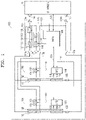
FIG. 1 illustrates a battery system according to an example embodiment; -
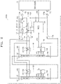
FIG. 2 illustrates a battery system according to another example embodiment; -
FIG. 3 illustrates a battery module according to an example embodiment; -
FIG. 4A illustrates a film heater according to an example embodiment; -
FIG. 4B illustrates a film heater according to another example embodiment; -
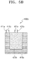
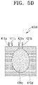
FIGS. 5A through 5D illustrate heating elements according to example embodiments; -
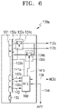
FIG. 6 illustrates a battery module including the heating element ofFIGS. 5A through 5D , according to an example embodiment; -
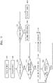
FIG. 7 is a flowchart for describing a method of controlling a battery system according to an example embodiment; and -
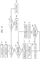
FIG. 8 is a flowchart for describing a method of controlling a battery system according to another example embodiment. - Example embodiments will now be described more fully hereinafter with reference to the accompanying drawings; however, they may be embodied in different forms and should not be construed as limited to the embodiments set forth herein. Rather, these embodiments are provided so that this disclosure will be thorough and complete, and will fully convey example implementations to those skilled in the art.
- In the drawing figures, the dimensions of layers and regions may be exaggerated for clarity of illustration. It will also be understood that when a layer or element is referred to as being "on" another layer or substrate, it can be directly on the other layer or substrate, or intervening layers may also be present. Further, it will be understood that when a layer is referred to as being "under" another layer, it can be directly under, and one or more intervening layers may also be present. In addition, it will also be understood that when a layer is referred to as being "between" two layers, it can be the only layer between the two layers, or one or more intervening layers may also be present. Like reference numerals refer to like elements throughout.
- As used herein, the term "and/or" includes any and all combinations of one or more of the associated listed items. Expressions such as "at least one of," when preceding a list of elements, modify the entire list of elements and do not modify the individual elements of the list.
- The terms used in the present specification are only used to describe specific embodiment, and are not intended to limit the present disclosure. The singular forms "a," "an" and "the" are intended to include the plural forms as well, unless the context clearly indicates otherwise. In the present specification, it is to be understood that the terms such as "including" or "having," etc., are indented to indicate the existence of the features, numbers, steps, actions, components, parts, or combination thereof disclosed in the specification, and are not intended to preclude the possibility that one or more other features, numbers, steps, actions, components, parts, or combinations thereof may exist or may be added. It will be understood that although the terms "first", "second", etc. may be used herein to describe various components, these components should not be limited by these terms. These terms are only used to distinguish one component from another.
-
FIG. 1 illustrates a battery system according to an example embodiment. - Referring to
FIG. 1 , abattery system 100 may include abattery management module 110, at least one ofbattery modules controllers battery system 100 may be charged by being connected to acharger 10, discharged by being connected to a load. - The
battery management module 110 may includeexternal terminals battery terminals 111a and 111b,heating terminals main switch 114 between theexternal terminal 101a and the battery terminal 111a, and aheating switch 117 between theexternal terminal 101a and theheating element 112a. - The
battery modules first battery module 130 and asecond battery module 150. - The
first battery module 130 may include at least onefirst battery cell 131 connected to thebattery terminals 111a and 111b, afirst heating element 132, and a first control switch between thefirst heating element 132 and theheating terminal 112a. - The
second battery module 150 may include at least onesecond battery cell 151 connected to thebattery terminals 111a and 111b, asecond heating element 152, and asecond control switch 154 between thesecond heating element 152 and theheating terminal 112a. - In
FIG. 1 , thebattery system 100 includes twobattery modules battery system 100 may include only one battery module, or may include three or more battery modules, which may be connected in series or in parallel. - The
controllers microcontroller 120 and at least one ofanalog front ends - In
FIG. 1 , twoanalog front ends battery system 100 corresponding to twobattery modules - The
microcontroller 120 may be mounted on thebattery management module 110, and the first and secondanalog front ends second battery modules - The
external terminals battery system 100 to an external device such as a load, or may receive power to be stored in thebattery system 100 from an external device such as thecharger 10. Theexternal terminals terminals charger 10. In an example, the firstexternal terminal 101a is positive, and the secondexternal terminal 101b is negative, but this is merely an example. - The
battery terminals 111a and 111b may be configured to be connected to the first andsecond battery modules first battery cell 131 of thefirst battery module 130 and thesecond battery cell 151 of thesecond battery module 150 may be connected in parallel between thebattery terminals 111a and 111b. Thefirst battery cell 131 and thesecond battery cell 151 may receive a charging current and output a discharging current through thebattery terminals 111a and 111b. - A
first switch circuit 113 may be arranged between theexternal terminal 101a and the battery terminal 111a. Thefirst switch circuit 113 may include amain switch 114 and amain fuse 115. - The
main switch 114 may be connected between theexternal terminal 101a and the battery terminal 111a. Themain switch 114 may be controlled by amain control signal 121 output by themicrocontroller 120. - The
first switch circuit 113 may include a current sensor, and the current sensor may detect the charging and discharging currents input and output to/from theexternal terminals sensing data 123 to themicrocontroller 120. Thefirst switch circuit 113 may include a voltage sensor that detects a voltage between theexternal terminals sensing data 113. - According to another example, the
first switch circuit 113 may be arranged between theexternal terminal 101b and thebattery terminal 111b. - The
heating terminals second battery modules first heating element 132 of thefirst battery module 130 and thesecond heating element 152 of thesecond battery module 150 may be connected in parallel between theheating terminals - According to another example, the
heating terminal 112b may be omitted, and thefirst heating element 132 and thesecond heating element 132 and thesecond heating element 152 may be connected between theheating element 112a and thebattery terminal 111b. - A
second switch circuit 116 may be arranged between thesecond terminal 101a and theheating terminal 112a. Thesecond switch circuit 116 may include aheating switch 117 and afuse 118. - The
heating switch 117 may be connected between theexternal terminal 101a and theheating terminal 112a. Theheating switch 117 may be controlled by aheating control signal 122 output by themicrocontroller 120. - According to another example, the
second switch circuit 116 may be arranged between theexternal terminal 101b and theheating terminal 112b. - The
microcontroller 120 may receive thesensing data 123, may output amain control signal 121 for controlling themain switch 114, and may output aheating control signal 122 for controlling theheating switch 117. Themicrocontroller 120 may communicate with the first and second analog front ends 140 and 160 through afirst communication line 124. Thefirst communication line 124 may be a communication line for performing a controller area network (CAN) communication. - The
microcontroller 120 may communicate with thecharger 10 through asecond communication line 125. Themicrocontroller 120 may detect connection with thecharger 10 through thesecond communication line 125, and may request thecharger 10 to output a voltage so as to operate in a charging mode. For example, themicrocontroller 120 may request thecharger 10 to supply a heating voltage or may request thecharger 10 to supply a charging voltage. According to another example, themicrocontroller 120 may detect that a voltage is being applied to theexternal terminals sensing data 123, thereby operating in the charging mode. - According to an example, the
microcontroller 120 may be awakened through a signal output by thecharger 10 through thesecond communication line 125. According to another example, themicrocontroller 120 may be awakened in response to the voltage applied to theexternal terminals - The first and
second battery cells second battery cells second battery cells - The
first battery cells 131 may be connected to thebattery terminals 111a and 111b, and afuse 135 may be connected to thefirst battery cells 131 in series. Thesecond battery cells 151 may be connected to thebattery terminals 111a and 111b, and afuse 155 may be connected to thesecond battery cells 151 in series. - In
FIG. 1 , each of thefirst battery cells 131 and thesecond battery cells 151 are connected in series. However, this is just an example, and thefirst battery cells 131 and thesecond battery cells 151 may be connected to each other in parallel or in series and in parallel. The number offirst battery cells 131 and the number ofsecond battery cells 151 is not limited to the examples described herein. - The first and
second heating elements heating terminals heating elements - The first and
second heating elements - When a voltage is applied to the heating element pattern, heat may be emitted to increase the temperature of the first and
second battery cells second heating elements second battery cells - First and
second control circuits second heating elements first control circuit 133 may be arranged between thefirst heating element 132 and theheating terminal 112a, and thesecond control circuit 153 may be arranged between thesecond heating element 152 and theheating terminal 112a. Thefirst control circuit 133 may include afirst control switch 134 controlled by thefirst control signal 141 output by the first analogfront end 140, and thesecond control circuit 153 may include asecond control switch 154 controlled by thesecond control signal 161 output by the second analogfront end 160. - The
first control signal 141 and thesecond control signal 161 may be, e.g., pulse width modulation (PWM) signals having a duty ratio. The first and second analog front ends 140 and 160 may adjust the duty ratio of the first and second control signals 141 and 161, thereby adjusting a heating value of heat generated by the first andsecond heating elements microcontroller 120. - The first and second analog front ends 140 and 160 may receive
battery sensing data heater sensing data 143 and 163. - The
battery sensing data second battery cells second battery cells second battery cells - The
heating sensing data 143 and 163 may include the first and second heater temperatures of the first andsecond heating elements second heating element - The first and
second battery modules second battery modules second battery cells second heating elements - The first and second analog front ends 140 and 160 may communicate with each other through a
third communication line 144. Thethird communication line 144 may be a communication line for performing a CAN communication. The CAN communication may be performed between themicrocontroller 120 and the first and second analog front ends 140 and 160 through the first andthird communication lines battery sensing data heater sensing data 143 and 163 to themicrocontroller 120 through the first andthird communication lines microcontroller 120 may transmit control instructions to the first and second analog front ends 140 and 160 through the first andthird communication lines - The
microcontroller 120 may detect connection with thecharger 10. For example, themicrocontroller 120 may detect connection with thecharger 10 through thesecond communication line 125. Themicrocontroller 120 may detect first and second cell temperatures of first and second battery cells through thebattery sensing data - The
microcontroller 120 may turn off themain switch 114 and turn on theheating switch 117 when the first and second cell temperatures are lower than a first reference value. According to an example, when any one of the first and second cell temperatures is lower than the first reference value, themicrocontroller 120 may turn off themain switch 114 and turn on theheating switch 117. For example, the first reference value may be 0 degrees Celsius. However, the first reference value may be set to a temperature lower than or higher than 0 degrees Celsius according to the temperature characteristics of the first andsecond battery cells main switch 114 means that themain switch 114 is opened so that theexternal terminal 101a and the battery terminal 111a are insulated from each other. Turning on theheating switch 117 means that theheating switch 117 is shorted or closed so that theexternal terminal 101a and theheating terminal 112a are electrically connected to each other. - When the first and second cell temperatures are lower than the first reference value, the
microcontroller 120 may request thecharger 10 to supply heating power before turning on theheating switch 117. Thecharger 10 may output a heating voltage to theexternal terminals microcontroller 120. Themicrocontroller 120 may detect the heating voltage applied to theexternal terminals heating switch 117. In this case, themain switch 114 may be in a turned off state. - Also, the
microcontroller 120 may turn on the first and second control switches 134 and 154 through the first and second analog front ends 140 and 160, thereby supplying the heating power from thecharger 10 to the first andsecond heating elements microcontroller 120 may determine the duty ratio of the first and second control signals 141 and 161 output by the first and second analog front ends 140 and 160 to control the first and second control switches 134 and 154, based on the first and second cell temperatures. - For example, when the first cell temperature is higher than the second cell temperature, the
microcontroller 120 may determine the duty ratio of thefirst control signal 141 to be lower than the duty ratio of thesecond control signal 161. For example, when the first cell temperature reaches a second reference value in a state in which the second cell temperature does not reach the second reference value, themicrocontroller 120 may transmit a control instruction for reducing the duty ratio of thefirst control signal 141 to the first analogfront end 140. The duty ratio of thefirst control signal 141 may be lower than the duty ratio of thesecond control signal 161. - When the first and second cell temperatures are increased by the first and
second heating elements microcontroller 120 may be configured to supply charging power from thecharger 10 to the first andsecond battery cells heating switch 117 and turning on themain switch 114. According to an example, when the first and second cell temperatures are higher than the second reference value, themicrocontroller 120 may turn off theheating switch 117 and turn on themain switch 114. The second reference value may be higher than the first reference value and may be, for example, 5 degrees Celsius. However, the second reference value may be set to be lower than or higher than 5 degrees Celsius according to temperature characteristics of the first andsecond battery cells - According to an example, the voltage of the charging power and the voltage of the heating power may be the same. According to another example, the voltage of the charging power and the voltage of the heating power may be different from each other, and for example, the voltage of the charging power may be higher than the voltage of the heating power.
- According to another example, when the first and second cell temperatures are higher than the second reference value, the
microcontroller 120 may turn off theheating switch 117 and may request thecharger 10 to supply the charging power. Thecharger 10 may output the charging voltage to theexternal terminals microcontroller 120. Themicrocontroller 120 may detect the charging voltage applied to theexternal terminals main switch 114. - As described above, according to an example, when the first and second cell temperatures are equal to or higher than a preset first reference value, charging of the first and
second battery cells second battery cells second battery cells - Also, according to an example, the heating power for increasing the first and second cell temperatures of the first and
second battery cells second battery cells charger 10. Thus, a case in which the first andsecond battery cells -
FIG. 2 illustrates a battery system according to another example embodiment. - Referring to
FIG. 2 , abattery system 100a may include abattery management module 110, at least onebattery modules controllers battery system 100a is substantially the same as thebattery system 100 ofFIG. 1 except that the first andsecond battery modules - The
first battery cells 131 of thefirst battery module 130 and thesecond battery cells 151 of thesecond battery module 150 may be connected between thebattery terminals 111a and 111b in series. The charging voltage for charging the first andsecond battery cells second battery cells FIG. 1 . In the example embodiment ofFIG. 1 , when the voltage of the charging power and the voltage of the heating power are the same, according to the embodiment ofFIG. 2 , the voltage of the charging power may be about twice as the voltage of the heating power. - The
microcontroller 120 may detect connection with thecharger 10 through thesecond communication line 125. Themicrocontroller 120 may detect first and second cell temperatures of first and second battery cells through the first and second analog front ends 140 and 160. In this case, themain switch 114 may be in a turned off state. - When the first and second cell temperatures are lower than the first reference value, the
microcontroller 120 may request thecharger 10 to supply the heating voltage. Thecharger 10 may output the heating voltage to theexternal terminals microcontroller 120. Themicrocontroller 120 may detect the heating voltage applied to theexternal terminals heating switch 117. Themicrocontroller 120 may turn on the first and second control switches 134 and 154 through the first and second analog front ends 140 and 160, thereby supplying the heating power from thecharger 10 to the first andsecond heating elements - When the first and second cell temperatures are increased by the first and
second heating elements microcontroller 120 may turn off theheating switch 117 and may request thecharger 10 to supply the charging power. Thecharger 10 may output the charging voltage to theexternal terminals microcontroller 120. Themicrocontroller 120 may detect the charging voltage applied to theexternal terminals main switch 114, thereby supplying charging power from thecharger 10 to the first andsecond battery cells - According to the present example embodiment, even when the charging voltage and the heating voltage are different from each other, as communication is performed between the
microcontroller 120 and thecharger 10, after the temperature of the first andsecond battery cells second battery cells -
FIG. 3 illustrates a battery module according to an example embodiment. - Referring to
FIG. 3 , abattery module 200 may include abattery body case 210,battery cells 220, athermal pad 230, athermal plate 240, afilm heater 250, aninsulator 260, and a cover case 279. Thebattery module 200 may correspond to the first andsecond battery modules FIGS. 1 and2 . - The
battery body case 210 and thecover case 270 may protect thebattery cells 220 and a protection circuit, and the like from external shock, moisture, and the like. The protection circuit may be mounted on thebattery body case 210. The protection circuit may include an analog front end, a current and temperature sensor, a cell balancing circuit, a communication terminal, and the like. The protection circuit may be mounted on a circuit board fixed to thebattery body case 210. Thebattery cells 220 may be arranged in thebattery body case 210, and thebattery cells 220 may correspond to the firsts andsecond battery cells FIGS. 1 and2 . - The
thermal pad 230 may be arranged on thebattery cells 220. Thethermal pad 230 may transfer heat generated in thefilm heater 250 to thebattery cells 220. Thethermal pad 230 may dissipate heat generated in thebattery cells 220 to the outside. Thethermal pad 230 may insulate thefilm heater 250 and thebattery cells 220 from each other. A thermal glue instead of thethermal pad 230 may also be used. - The
thermal plate 240 may be arranged on thethermal pad 230. Thethermal plate 240 may fix thefilm heater 250 and may diffuse heat generated in thefilm heater 250 to thebattery cells 220. - The
film heater 250 may be arranged on thethermal plate 240. Thefilm heater 250 may include a heating element pattern arranged on the insulating film. When the heating voltage is applied to the heating element pattern, heat may be emitted so that the temperature of thebattery cells 220 may be increased. As shown, thebattery cells 220 may be arranged adjacent to thefilm heater 250. Thefilm heater 250 may correspond to the first andsecond heating elements FIGS. 1 and2 . Thefilm heater 250 will be described in more detail below with reference toFIGS. 4 and5 . - The
insulator 260 may be arranged on thefilm heater 250. Theinsulator 260 may prevent heat generated from thefilm heater 250 from being lost to the outside. Thecover case 270 may be arranged on theinsulator 260. Thecover case 270 may be coupled to thebattery body case 210 by plastic laser welding. -
FIG. 4A illustrates a film heater according to an example embodiment. - Referring to
FIG. 4A , afilm heater 300a may include an insulatingfilm 320, and aheating element pattern 310a arranged on the insulatingfilm 320 to have a desired heating size.Connection terminals heating element pattern 310a. - The insulating
film 320 may include a plastic film made of one or more plastic materials selected from, e.g., polyethylene terephthalate (PET), polyimide (PI), poly acrylonitrile (PAN), polyurethane (PU), silicon, polycarbonate (PC), Teflon, liquid crystal polymer (LCP), poly ether ether ketone (PEEK), polyethersulphone (PES), polyacrylate (PAR), polyetherimide (PEI), polyethylene naphthalate (PEN), polyphenylene sulfide (PPS), polyallylate, cellulose triacetate (CTA), and cellulose acetate propionate (CAP). - The
heating element pattern 310a may be a planar heating element having a small width. Theheating element pattern 310a may have a substantially constant width according to a longitudinal direction. According to another example, theheating element pattern 310a may have different widths according to the longitudinal direction so that a heating value per unit area of a certain region may be differently set when the same current flows through theheating element pattern 310a. - The planar heating element maybe formed using, e.g., a ceramic resistor. The planar heating element may be, e.g., a carbon-based heating element and maybe formed of a material such as a carbon pulp heating paper, a carbon fiber yarn woven heating element, or a carbon cotton heating element. The planar heating element may be formed by, e.g., weaving a fine metal wire.
- The
heating element pattern 310a may be formed by printing a heating element composition on an upper surface of the insulatingfilm 320. Theheating element pattern 310a may be formed by printing the heating element composition on the upper surface of the insulatingfilm 320, and then thermally curing and aging. As a printing method of the heating element composition, screen printing, gravure printing (or roll-to-roll gravure printing), comma coating (or roll-to-roll comma coating), flexo, imprinting, offset printing, etc., maybe used. Curing may be performed at, e.g., ioo°C to i8o°C, and aging may be performed at, e.g., 250°C to 350°C. - According to an example, the heating element composition may include a mixed binder, conductive particles, an organic solvent, and a dispersant. The conductive particles may include silver powder and carbon nanotube particles and may further include graphite particles. The heating element composition may have a density of, e.g., 2 g/cm3 or less. According to another example, the heating element composition may include a mixed binder, carbon particles, a metal powder, an organic solvent, and a dispersant. The carbon particles may include carbon nanotube particles and graphite particles. The heating element composition may be implemented in the form of paint, ink, or paste by controlling the amount of organic solvent used.
- According to another example, the
heating element pattern 310a may be formed of a conductive wire. The conductive wire may include at least a metal wire. The metal wire may be covered with a self-adhesive insulating film. For example, a metal wire such as copper, iron, gold, copper nickel, nickel chromium, iron nickel chromium, or the like may be used, but other materials may be used as long as they have conductivity. In consideration of electrical resistance, durability, and cost, copper or a copper alloy in which zinc, lead, tin, silver, aluminum, nickel, beryllium, zirconium, and the like are combined singly or in the plural, may be used as the metal wire. - The
film heater 300a may have a plurality of heating regions HR1, HR2, and HR3 with different heating values per unit area. The third heating region HR3 may be defined adjacent to the center of thefilm heater 300a, and theheating element pattern 310a may be arranged so that the density of theheating element pattern 310a is low to have a lowest heating value per unit area, or the separation distance between adjacent linear patterns is large. The first heating region HR1 may be defined adjacent to the periphery of thefilm heater 300a, and theheating element pattern 310a may be arranged so that the density of theheating element pattern 310a is high to have a highest heating value per unit area, or the separation distance between adjacent linear patterns is small. The second heating region HR2 may be arranged between the first heating region HR1 and the third heating region HR3, and theheating element pattern 310a may be arranged to have a heating value that is less than that of the first heating region HR1 and greater than the third heating region HR3. - The
film heater 300a may have a rectangular planer shape. The second and third heating regions HR2 and HR3 may have a circular planar shape, as shown inFIG. 4A . Thefilm heater 300a may have a plurality of heating regions HR1, HR2, and HR3 with different heating values per unit area so that the temperature of battery cells arranged in thefilm heater 300a may be constantly increased. -
FIG. 4B illustrates a film heater according to another example embodiment. - Referring to
FIG. 4A , thefilm heater 300b may include an insulatingfilm 320, and aheating element pattern 310b arranged to have a desired heating size on the insulatingfilm 320.Connection terminals heating element pattern 310b. Thefilm heater 300b may be substantially the same as thefilm heater 300a ofFIG. 4A except for the planar shape of theheating element pattern 310b, and the same components will not be repeatedly described. A material for theheating element pattern 310b may be the same as theheating element pattern 310a ofFIG. 4A . - The
film heater 300b may have a plurality of heating regions HR1 and HR2 with different heating values per unit area. The first heating region HR1 may be defined adjacent to the periphery of thefilm heater 300b, and theheating element pattern 310b may be arranged so that the density of theheating element pattern 310b is high to have a highest heating value per unit area, a lower separation distance between adjacent linear patterns, or a width thereof is large. The second heating area HR2 may be defined adjacent to the center of thefilm heater 300b, and theheating element pattern 310b may be arranged so that the density of theheating element pattern 310b is low to have a lowest heating value per unit area, a large separation distance between adjacent linear patterns, or a width thereof is small. - The first and second heating regions HR1 and HR2 may have a rectangular planar shape to correspond to the planar shape of the
film heater 300b, as shown inFIG. 4B . Thefilm heater 300b may have a plurality of heating regions HR1 and HR2 with different heating values per unit area so that the temperature of battery cells arranged in thefilm heater 300b may be constantly increased. -
FIGS. 5A through 5D illustrate heating elements according to example embodiments. - Referring to
FIG. 5A , aheating element 400a may include afirst film heater 410a located on the periphery of theheating element 400a, and asecond film heater 420a located inside thefirst film heater 410a. Thefirst film heater 410a may surround thesecond film heater 420a. Thefirst film heater 410a may includefirst connection terminals second film heater 420a may includesecond connection terminals first connection terminals second connection terminals first film heater 410a may be greater than heating power supplied to thesecond film heater 420a. - Referring to
FIG. 5B , aheating element 400b may include afirst film heater 410b located on the periphery of theheating element 400b, and asecond film heater 420b located inside thefirst film heater 410b. Thefirst film heater 410b may surround three edges of thesecond film heater 420b. Thefirst film heater 410b may includefirst connection terminals second film heater 420b may includesecond connection terminals first film heater 410b and heating power supplied to thesecond film heater 420b may be different from each other. - Referring to
FIG. 5C , aheating element 400c may include afirst film heater 410c located on the periphery of theheating element 400c, and asecond film heater 420c surrounded by thefirst film heater 410c. Theheating element 400c has a rectangular planar shape, but thesecond film heater 420c may have a circular planar shape. Thefirst film heater 410c may includefirst connection terminals second film heater 420c may includesecond connection terminals first film heater 410c and the heating power supplied to thesecond film heater 420c may be different from each other. - Referring to
FIG. 5D , aheating element 400d may include afirst film heater 410d located on the periphery of theheating element 400d, and asecond film heater 420d having an elliptical planar shape and surrounded by thefirst film heater 410d. Thefirst film heater 410d may includefirst connection terminals second film heater 420d may includesecond connection terminals first film heater 410d and the heating power supplied to thesecond film heater 420d may be different from each other. -
FIG. 6 illustrates a battery module including the heating element ofFIGS. 5A through 5D according to an example embodiment. - Referring to
FIG. 6 , abattery module 130a may include at least onefirst battery cell 131, afirst film heater 132a and asecond film heater 132b, afirst control switch 134a between thefirst film heater 132a and theheating terminal 112a, asecond control switch 134b between thesecond film heater 132b and aheating terminal 112a, and a first analogfront end 140 that outputs afirst control signal 141a to thefirst control switch 134a and outputs asecond control signal 141b to thesecond control switch 134b. - In the
battery module 130a, when compared with thefirst battery module 130 ofFIG. 1 , thebattery module 130a is substantially the same as thefirst battery module 130 ofFIG. 1 except that the first andsecond film heaters first heating element 132 are use and the first andsecond control switches control switch 134 are used. A redundant description of the same components may be omitted. - The first analog
front end 140 may independently output the first andsecond control signals second control switches front end 140 may receive heater sensing data 143a from thefirst film heater 132a and may receiveheater sensing data 143b from thesecond film heater 132b. - As shown in
FIGS. 5A through 5D , a heating element including the first andsecond film heaters second film heaters second control switches second control switches second control signals - The first and
second control signals second film heater 132b located inside thefirst heating element 132 may generate less heat than thefirst film heater 132a located on the periphery of thefirst heating element 132, and, correspondingly, the duty ratio of thefirst control signal 141a may be higher than the duty ratio of thesecond control signal 141b. -
FIG. 7 is a flowchart for describing a method of controlling a battery system according to an example embodiment. - Referring to
FIG. 7 withFIG. 1 , themicrocontroller 120 may be awakened (S10). According to an embodiment, themicrocontroller 120 may be awakened in response to a wakeup signal output by thecharger 10 through thesecond communication line 125, and may detect that thecharger 10 has been connected to themicrocontroller 120 through thesecond communication line 125. According to another example, themicrocontroller 120 may be awakened in response to a voltage applied to theexternal terminals microcontroller 120 may be awakened in response to a user's input or a signal from another controller. - The
microcontroller 120 may collect data (S20). For example, themicrocontroller 120 may collect voltage values applied to theexternal terminals sensing data 123, and collect charging and discharging current values input and output through theexternal terminals microcontroller 120 may communicate with the first and second analog front ends 140 and 160 through the first andthird communication lines first battery cells 131, a current value and a heater temperature value of thefirst heating element 132, a cell voltage value and a second cell temperature value of thesecond battery cells 151, and a current value and a heater temperature value of thesecond heating element 152. - The
microcontroller 120 may collect the voltage value applied to theexternal terminals sensing data 123, and may detect that thecharger 10 has been connected to themicrocontroller 120 based thereon. - The
microcontroller 120 may determine whether a current operation mode is a charging mode (S30). - When the current operation mode is not the charging mode, the
microcontroller 120 may determine whether the current operation mode is a discharging mode (S31). - When the current operation mode is the discharging mode, the
microcontroller 120 may perform a normal operation (S32). For example, themicrocontroller 120 may turn on themain switch 114. - When the current operation mode is not the discharging mode, the
microcontroller 120 may operate in a standby mode (S33). - Referring again to operation S30, when the current operation mode is the charging mode (S30-Yes), the
microcontroller 120 may compare the first cell temperature value and the second cell temperature value with a first temperature (S40). The first temperature may be a first reference value, for example, 0 degrees Celsius. - The
microcontroller 120 may operate in a heating operation mode when one of the first cell temperature value and the second cell temperature value is lower than the first temperature (S50). For example, themicrocontroller 120 may turn off themain switch 114 and may turn on theheating switch 117. Themicrocontroller 120 may turn on the first and second control switches 134 and 154 through the first and second analog front ends 140 and 160, thereby supplying heating power from thecharger 10 to the first andsecond heating elements second heating elements - The
microcontroller 120 may compare the first cell temperature value and the second cell temperature value with a second temperature (S60). The second temperature may be a second reference value higher than the first temperature, for example, 5 degrees Celsius. Themicrocontroller 120 may perform a heating operation mode continuously when one of the first cell temperature value and the second cell temperature value is lower than the second temperature. - The
microcontroller 120 may stop the heating operation mode and start charging normally when both the first cell temperature value and the second cell temperature value are higher than the second temperature (S70). - Also, referring again to operation S40, the
microcontroller 120 may skip the heating operation mode and start charging normally when both the first cell temperature value and the second cell temperature value are higher than the first temperature (S70). Themicrocontroller 120 may be configured to turn off theheating switch 117 and turn on themain switch 114, thereby supplying charging power from thecharger 10 to the first andsecond battery cells -
FIG. 8 is a flowchart for describing a method of controlling a battery system according to another example embodiment. - Referring to
FIG. 8 withFIG. 1 , themicrocontroller 120 may perform operations S10 through S40 described above with reference toFIG. 7 . - The
microcontroller 120 may prepare a heating operation when one of the first cell temperature value and the second cell temperature value is lower than the first temperature (S51). For example, themicrocontroller 120 may turn off themain switch 114 and request thecharger 10 to supply a heating voltage through thesecond communication line 125. Thecharger 10 may output the heating voltage to theexternal terminals microcontroller 120. When the heating voltage applied to theexternal terminals microcontroller 120 may turn on theheating switch 117. Themicrocontroller 120 may turn on the first and second control switches 134 and 154 through the first and second analog front ends 140 and 160, thereby supplying heating power from thecharger 10 to the first andsecond heating elements 132 and 152 (S52). - The
microcontroller 120 may control the heating operation based on the first cell temperature and the second cell temperate (S53). The first and second analog front ends 140 and 160 may output the first and second control signals 141 and 161 having a duty ratio so as to control the first and second control switches 134 and 154. For example, the first cell temperature may not have reached the second temperature; when the second cell temperature reaches the second temperature first, the duty ratio of thesecond control signal 161 may be reduced. In this case, the duty ratio of thesecond control signal 161 may be lower than the duty ratio of the firstsecond signal 141. According to another example, themicrocontroller 120 may adjust the duty ratio of the first and second control signals 141 and 161 based on the first cell temperature and the second cell temperature. For example, themicrocontroller 120 may reduce the duty ratio of the first and second control signals 141 and 161 as the first cell temperature and the second cell temperature are increased. The first and second cell temperatures may be increased by heat generated by the first andsecond heating elements - The
microcontroller 120 may compare the first cell temperature value and the second cell temperature value with the second temperature (S60). Themicrocontroller 120 may control the heating operation continuously when one of the first cell temperature value and the second cell temperature is lower than the second temperature (S53). - The
microcontroller 120 may stop the heating operation when both the first cell temperature value and the second cell temperature value are higher than the second temperature (S61). Themicrocontroller 120 may check whether both the first cell temperature value and the second cell temperature value are maintained to be higher than the second temperature for a preset time (e.g., one minute). When both the first cell temperature value and the second cell temperature value are maintained to be higher than the second temperature for a preset time (for example, one minute), themicrocontroller 120 may turn off the first and second control switches 134 and 154 through the first and second analog front ends 140 and 160. Themicrocontroller 120 may turn off theheating switch 117 and may request thecharger 10 to supply charging power through thesecond communication line 125. Thecharger 10 may output a charging voltage to theexternal terminals microcontroller 120. Themicrocontroller 120 may detect the charging voltage applied to theexternal terminals main switch 114, thereby supplying the charging power from thecharger 10 to the first andsecond battery cells - Referring again to operation S40, when both the first cell temperature value and the second cell temperature value are higher than the first temperature, the
microcontroller 120 may turn off theheating switch 117 and may request thecharger 10 to supply the charging power through thesecond communication line 125. Thecharger 10 may output the charging voltage to theexternal terminals microcontroller 120. Themicrocontroller 120 may detect the charging voltage applied to theexternal terminals main switch 114, thereby supplying the charging power from thecharger 10 to the first andsecond battery cells - By way of summation and review, due to the characteristics of the lithium-ion battery, the deterioration of the battery may be accelerated when the battery is rapidly charged in a low temperature environment.
- As described above, after a cell temperature is increased by using power supplied from a charger, a battery may be charged so that a battery system capable of fast charging even in a low temperature environment can be provided.
- Herein, for the sake of brevity, conventional electronics, control systems, software development and other functional aspects of the systems may not be described in detail. Furthermore, the connecting lines, or connectors shown in the various figures presented are intended to represent example functional relationships and/or physical or logical couplings between the various elements. It should be noted that many alternative or additional functional relationships, physical connections or logical connections may be present in a practical device.
- Furthermore, recitation of ranges of values herein are merely intended to serve as a shorthand method of referring individually to each separate value falling within the range, unless otherwise indicated herein, and each separate value is incorporated into the specification as if it were individually recited herein. Finally, the steps of all methods described herein can be performed in any suitable order unless otherwise indicated herein or otherwise clearly contradicted by context, and are not limited to the order in which the steps are described. The use of any and all examples, or example language (e.g., "such as") provided herein, is intended merely to better illuminate the embodiments and does not pose a limitation on the scope of the embodiments unless otherwise claimed.
- Example embodiments have been disclosed herein, and although specific terms are employed, they are used and are to be interpreted in a generic and descriptive sense only and not for purpose of limitation. In some instances, as would be apparent to one of ordinary skill in the art as of the filing of the present application, features, characteristics, and/or elements described in connection with a particular embodiment may be used singly or in combination with features, characteristics, and/or elements described in connection with other embodiments unless otherwise specifically indicated. Accordingly, it will be understood by those of skill in the art that various changes in form and details may be made without departing from the scope of the present invention as set forth in the following claims.
Claims (13)
- A battery system, comprising:a battery management module including an external terminal, a battery terminal, a heating terminal, a main switch between the external terminal and the battery terminal, and a heating switch between the external terminal and the heating terminal;at least one battery module including at least one battery cell connected to the battery terminal, a heating element, and a control switch between the heating element and the heating terminal; anda controller configured to detect connection with a charger, and to detect a cell temperature of the at least one battery cell,wherein, when the cell temperature is lower than a first reference value, the controller is configured to turn off the main switch and turn on the heating switch and the control switch to supply heating power from the charger to the heating element, andwhen the cell temperature is higher than a second reference value, the controller is configured to turn off the heating switch and turn on the main switch to supply charging power from the charger to the at least one battery cell.
- The battery system as claimed in claim 1, wherein the controller includes:a microcontroller mounted on the battery management module and configured to control the main switch and the heating switch; andat least one analog front end respectively mounted on the at least one battery module and configured to detect the cell temperature, transmit the detected cell temperature to the microcontroller, and output a control signal to the control switch according to control of the microcontroller.
- The battery system as claimed in claim 2, wherein:the control signal is a pulse width modulation signal, andthe microcontroller is configured to determine a duty ratio of the control signal according to the cell temperature.
- The battery system as claimed in any one of the preceding claims, wherein the at least one battery module includes:a first battery module including at least one first battery cell, a first heating element, and a first control switch between the first heating element and the heating terminal; anda second battery module including at least one second battery cell, a second heating element, and a second control switch between the second heating element and the heating terminal.
- The battery system as claimed in claim 4, wherein:the at least one first battery cell and the at least one second battery cell are connected to each other in series,the controller is configured to request the charger to supply a heating voltage when one of a first cell temperature of the at least one first battery cell and a second cell temperature of the at least one second battery cell is lower than the first reference value, andthe controller is configured to request the charger to supply a higher charging voltage than the heating voltage when both the first cell temperature and the second cell temperature are higher than the second reference value.
- The battery system as claimed in claim 5, wherein, when the first cell temperature of the at least one first battery cell reaches the second reference value and the second cell temperature of the at least one second battery cell is lower than the second reference value, the controller is configured to output a first control signal having a first duty ratio to the first control switch and output a second control signal having a second duty ratio higher than the first duty ratio to the second control switch.
- The battery system as claimed in any one of the preceding claims, wherein the second reference value is equal to or higher than the first reference value.
- The battery system as claimed in any one of the preceding claims, wherein:the heating element is a film heater having a plurality of regions with different heating values per unit area, andthe at least one battery cell includes a plurality of battery cells arranged on the film heater.
- The battery system as claimed in claim 8, wherein a heating value per unit area of a central region of the film heater is lower than a heating value per unit area of an edge region of the film heater.
- The battery system as claimed in any one of the preceding claims, wherein:the heating element includes a first film heater, and a second film heater that surrounds at least a portion of the first film heater,the at least one battery module includes a first control switch between the first film heater and the heating terminal, and a second control switch between the second film heater and the heating terminal, andthe controller is configured to output a second control signal having a higher duty ratio than a duty ratio of a first control signal output to the first control switch, to the second control switch.
- A method of controlling the battery system as claimed in any one of the preceding claims, the method comprising:detecting a connection with the charger;detecting a cell temperature of the at least one battery cell;when the cell temperature is lower than the first reference value, operating the controller to turn off the main switch and turn on the heating switch and the control switch so as to supply the heating power from the charger to the heating element; andwhen the cell temperature is higher than the second reference value, operating the controller to turn off the heating switch and turn on the main switch so as to supply the charging power from the charger to the at least one battery cell.
- The method as claimed in claim 11, wherein the supplying of the heating power from the charger to the heating element includes:detecting the cell temperature that is lower than the first reference value;turning off the main switch;requesting the charger to output a heating voltage;detecting the heating voltage applied to the external terminal;turning on the heating switch; andadjusting a duty ratio of a control signal for controlling the control switch.
- The method as claimed in claim 11 or 12, wherein the supplying of the charging power from the charger to the at least one battery cell includes:detecting that the cell temperature is maintained to be higher than the second reference value for a preset time;turning off the heating switch;requesting the charger to output a charging voltage;detecting the charging voltage applied to the external terminal; andturning on the main switch.
Applications Claiming Priority (1)
| Application Number | Priority Date | Filing Date | Title |
|---|---|---|---|
| KR1020210039695A KR102663022B1 (en) | 2021-03-26 | 2021-03-26 | Battery system and Method of controlling the same |
Publications (2)
| Publication Number | Publication Date |
|---|---|
| EP4064513A1 true EP4064513A1 (en) | 2022-09-28 |
| EP4064513B1 EP4064513B1 (en) | 2026-05-06 |
Family
ID=80928598
Family Applications (1)
| Application Number | Title | Priority Date | Filing Date |
|---|---|---|---|
| EP22163368.8A Active EP4064513B1 (en) | 2021-03-26 | 2022-03-21 | Battery system and method of controlling the same |
Country Status (4)
| Country | Link |
|---|---|
| US (1) | US12438205B2 (en) |
| EP (1) | EP4064513B1 (en) |
| KR (1) | KR102663022B1 (en) |
| CN (1) | CN115133176B (en) |
Families Citing this family (6)
| Publication number | Priority date | Publication date | Assignee | Title |
|---|---|---|---|---|
| US11843134B2 (en) * | 2021-11-10 | 2023-12-12 | GM Global Technology Operations LLC | Power control system for an electric vehicle including sacrificial protection device |
| KR102858672B1 (en) * | 2022-06-20 | 2025-09-15 | 주식회사 이랜텍 | Method and apparatus for detecting automatically number of battery pack in Energy Storage System |
| CN218215468U (en) * | 2022-07-18 | 2023-01-03 | 惠州市乐亿通科技有限公司 | Battery low-temperature heating charging system, vehicle-mounted air conditioning system and vehicle |
| CN117254163A (en) * | 2023-08-22 | 2023-12-19 | 华为数字能源技术有限公司 | Energy storage devices and energy storage systems |
| KR20250082668A (en) * | 2023-11-30 | 2025-06-09 | 삼성에스디아이 주식회사 | Apparatus for heating battery cell and battery module |
| KR102755004B1 (en) * | 2024-06-28 | 2025-01-14 | 타타대우모빌리티 주식회사 | Battery preheating method and system thereof |
Citations (3)
| Publication number | Priority date | Publication date | Assignee | Title |
|---|---|---|---|---|
| US20120032638A1 (en) * | 2009-11-30 | 2012-02-09 | Eun-Ey Jung | Battery pack and active cell balancing battery management system including the same |
| CN109755676A (en) * | 2019-03-07 | 2019-05-14 | 福建易动力电子科技股份有限公司 | A kind of balanced and heating integrated system of battery |
| US20210036388A1 (en) * | 2018-11-30 | 2021-02-04 | Contemporary Amperex Technology Co., Limited | Battery heating system and method |
Family Cites Families (12)
| Publication number | Priority date | Publication date | Assignee | Title |
|---|---|---|---|---|
| US7593823B2 (en) * | 2006-11-21 | 2009-09-22 | The Furukawa Electric Co., Ltd | Method and device for determining state of battery, and battery power supply system therewith |
| JP5462711B2 (en) | 2010-05-21 | 2014-04-02 | 古河電池株式会社 | Battery module |
| US9071056B2 (en) | 2011-11-04 | 2015-06-30 | Samsung Sdi Co., Ltd. | Apparatus and method for managing battery cell, and energy storage system |
| KR101473324B1 (en) * | 2011-11-04 | 2014-12-16 | 삼성에스디아이 주식회사 | Apparatus for managing battery, method for balancing battery cells, and energy storage system |
| CN108028443B (en) | 2015-09-28 | 2021-01-22 | 本田技研工业株式会社 | Power consumption control device |
| EP3255721B1 (en) * | 2016-06-08 | 2020-04-29 | Robert Bosch GmbH | Method for controlling a temperature of a battery cell |
| JP6863795B2 (en) * | 2017-03-30 | 2021-04-21 | ビークルエナジージャパン株式会社 | Battery energy storage system, battery management system and control method |
| KR20180131699A (en) | 2017-05-31 | 2018-12-11 | 주식회사 엘지엠 | Lithum ion battery case cooling structure for small sized ships and its controlling method |
| KR102196265B1 (en) | 2017-06-13 | 2020-12-29 | 주식회사 엘지화학 | Method and system for controling temperature of a battery pack |
| KR102312926B1 (en) * | 2017-10-19 | 2021-10-14 | 주식회사 엘지화학 | Heater control system of battery pack of parallel connection structure |
| KR20210108148A (en) * | 2020-02-25 | 2021-09-02 | 삼성에스디아이 주식회사 | Battery system |
| CN111129660B (en) | 2020-04-01 | 2020-10-27 | 惠州亿纬锂能股份有限公司 | Battery system, vehicle system, and battery system heating control method |
-
2021
- 2021-03-26 KR KR1020210039695A patent/KR102663022B1/en active Active
- 2021-12-27 US US17/562,380 patent/US12438205B2/en active Active
-
2022
- 2022-03-21 EP EP22163368.8A patent/EP4064513B1/en active Active
- 2022-03-25 CN CN202210305864.9A patent/CN115133176B/en active Active
Patent Citations (3)
| Publication number | Priority date | Publication date | Assignee | Title |
|---|---|---|---|---|
| US20120032638A1 (en) * | 2009-11-30 | 2012-02-09 | Eun-Ey Jung | Battery pack and active cell balancing battery management system including the same |
| US20210036388A1 (en) * | 2018-11-30 | 2021-02-04 | Contemporary Amperex Technology Co., Limited | Battery heating system and method |
| CN109755676A (en) * | 2019-03-07 | 2019-05-14 | 福建易动力电子科技股份有限公司 | A kind of balanced and heating integrated system of battery |
Also Published As
| Publication number | Publication date |
|---|---|
| CN115133176B (en) | 2026-02-10 |
| KR102663022B1 (en) | 2024-05-07 |
| CN115133176A (en) | 2022-09-30 |
| US12438205B2 (en) | 2025-10-07 |
| KR20220134261A (en) | 2022-10-05 |
| US20220311064A1 (en) | 2022-09-29 |
| EP4064513B1 (en) | 2026-05-06 |
Similar Documents
| Publication | Publication Date | Title |
|---|---|---|
| EP4064513B1 (en) | Battery system and method of controlling the same | |
| KR102614725B1 (en) | Battery protection circuit and battery pack including same | |
| US9184609B2 (en) | Overcurrent and overvoltage protecting fuse for battery pack with electrodes on either side of an insulated substrate connected by through-holes | |
| US20110318632A1 (en) | Battery cell integrated measurement sensor line and equalization resistor | |
| US20210098765A1 (en) | Battery module with flexible interconnector | |
| CN110999024B (en) | Battery protection circuit and battery pack including the same | |
| KR102505615B1 (en) | Battery pack | |
| US20130108894A1 (en) | Secondary battery | |
| KR102671847B1 (en) | Battery module with flexible interconnector | |
| US9142812B2 (en) | Battery pack | |
| US20140045001A1 (en) | Rechargeable battery and battery module | |
| KR20180121723A (en) | Battery heater, battery heater assembly and battery system comprising the same | |
| KR20170118993A (en) | Battery heater, battery system comprising the battery heater and manufacturing method thereof | |
| US11539085B2 (en) | Serviceable flex circuit for battery module | |
| KR20140038037A (en) | Battery pack | |
| CN112542870B (en) | Electronic equipment | |
| CN106849218B (en) | mobile phone rechargeable battery | |
| CN108682887A (en) | A kind of battery modules and electrokinetic cell system | |
| US20250087768A1 (en) | Battery pack and electric vehicle | |
| US20230207895A1 (en) | Battery apparatus and manufacturing method therefor | |
| US20210218253A1 (en) | Battery protection circuit and battery pack including same | |
| KR20250008797A (en) | Ultra-Capacitor Module | |
| KR20030075782A (en) | Lithium-ion Battery with PTC | |
| CN110050380B (en) | Heat radiation structure of cylindrical battery unit | |
| KR101826708B1 (en) | Battery heater, battery system comprising the battery heater and manufacturing method thereof |
Legal Events
| Date | Code | Title | Description |
|---|---|---|---|
| PUAI | Public reference made under article 153(3) epc to a published international application that has entered the european phase |
Free format text: ORIGINAL CODE: 0009012 |
|
| STAA | Information on the status of an ep patent application or granted ep patent |
Free format text: STATUS: REQUEST FOR EXAMINATION WAS MADE |
|
| 17P | Request for examination filed |
Effective date: 20220321 |
|
| AK | Designated contracting states |
Kind code of ref document: A1 Designated state(s): AL AT BE BG CH CY CZ DE DK EE ES FI FR GB GR HR HU IE IS IT LI LT LU LV MC MK MT NL NO PL PT RO RS SE SI SK SM TR |
|
| GRAP | Despatch of communication of intention to grant a patent |
Free format text: ORIGINAL CODE: EPIDOSNIGR1 |
|
| STAA | Information on the status of an ep patent application or granted ep patent |
Free format text: STATUS: GRANT OF PATENT IS INTENDED |
|
| RIC1 | Information provided on ipc code assigned before grant |
Ipc: H02J 7/00 20060101AFI20260216BHEP Ipc: H01M 10/615 20140101ALI20260216BHEP Ipc: H01M 10/44 20060101ALI20260216BHEP Ipc: H01M 10/48 20060101ALI20260216BHEP Ipc: H01M 10/42 20060101ALI20260216BHEP Ipc: H01M 10/653 20140101ALI20260216BHEP Ipc: H01M 10/6555 20140101ALI20260216BHEP Ipc: H01M 10/657 20140101ALI20260216BHEP Ipc: H02J 7/90 20260101ALI20260216BHEP Ipc: H02J 7/50 20260101ALN20260216BHEP Ipc: H02J 7/60 20260101ALN20260216BHEP |
|
| GRAS | Grant fee paid |
Free format text: ORIGINAL CODE: EPIDOSNIGR3 |
|
| GRAA | (expected) grant |
Free format text: ORIGINAL CODE: 0009210 |
|
| STAA | Information on the status of an ep patent application or granted ep patent |
Free format text: STATUS: THE PATENT HAS BEEN GRANTED |
|
| INTG | Intention to grant announced |
Effective date: 20260319 |
|
| AK | Designated contracting states |
Kind code of ref document: B1 Designated state(s): AL AT BE BG CH CY CZ DE DK EE ES FI FR GB GR HR HU IE IS IT LI LT LU LV MC MK MT NL NO PL PT RO RS SE SI SK SM TR |
|
| REG | Reference to a national code |
Ref country code: CH Ref legal event code: F10 Free format text: ST27 STATUS EVENT CODE: U-0-0-F10-F00 (AS PROVIDED BY THE NATIONAL OFFICE) Effective date: 20260506 Ref country code: GB Ref legal event code: FG4D |