EP4064437A1 - Battery, apparatus using same, and manufacturing method and device for battery - Google Patents
Battery, apparatus using same, and manufacturing method and device for battery Download PDFInfo
- Publication number
- EP4064437A1 EP4064437A1 EP20961839.6A EP20961839A EP4064437A1 EP 4064437 A1 EP4064437 A1 EP 4064437A1 EP 20961839 A EP20961839 A EP 20961839A EP 4064437 A1 EP4064437 A1 EP 4064437A1
- Authority
- EP
- European Patent Office
- Prior art keywords
- battery
- battery cell
- pressure relief
- battery cells
- guiding channel
- Prior art date
- Legal status (The legal status is an assumption and is not a legal conclusion. Google has not performed a legal analysis and makes no representation as to the accuracy of the status listed.)
- Pending
Links
- 238000004519 manufacturing process Methods 0.000 title 1
- 230000001681 protective effect Effects 0.000 claims abstract description 84
- 230000007246 mechanism Effects 0.000 claims abstract description 82
- 238000002360 preparation method Methods 0.000 claims abstract description 24
- 238000010586 diagram Methods 0.000 description 26
- 239000013543 active substance Substances 0.000 description 12
- 239000000463 material Substances 0.000 description 6
- 239000003792 electrolyte Substances 0.000 description 5
- 238000000034 method Methods 0.000 description 5
- HBBGRARXTFLTSG-UHFFFAOYSA-N Lithium ion Chemical compound [Li+] HBBGRARXTFLTSG-UHFFFAOYSA-N 0.000 description 4
- 229910001416 lithium ion Inorganic materials 0.000 description 4
- PNEYBMLMFCGWSK-UHFFFAOYSA-N Alumina Chemical compound [O-2].[O-2].[O-2].[Al+3].[Al+3] PNEYBMLMFCGWSK-UHFFFAOYSA-N 0.000 description 3
- WHXSMMKQMYFTQS-UHFFFAOYSA-N Lithium Chemical compound [Li] WHXSMMKQMYFTQS-UHFFFAOYSA-N 0.000 description 3
- 230000009471 action Effects 0.000 description 3
- 238000005336 cracking Methods 0.000 description 3
- 238000005516 engineering process Methods 0.000 description 3
- 229910052744 lithium Inorganic materials 0.000 description 3
- 229910000625 lithium cobalt oxide Inorganic materials 0.000 description 3
- BFZPBUKRYWOWDV-UHFFFAOYSA-N lithium;oxido(oxo)cobalt Chemical compound [Li+].[O-][Co]=O BFZPBUKRYWOWDV-UHFFFAOYSA-N 0.000 description 3
- 230000008569 process Effects 0.000 description 3
- 239000000126 substance Substances 0.000 description 3
- 239000004698 Polyethylene Substances 0.000 description 2
- 239000004743 Polypropylene Substances 0.000 description 2
- 229910052782 aluminium Inorganic materials 0.000 description 2
- XAGFODPZIPBFFR-UHFFFAOYSA-N aluminium Chemical compound [Al] XAGFODPZIPBFFR-UHFFFAOYSA-N 0.000 description 2
- 238000004146 energy storage Methods 0.000 description 2
- GELKBWJHTRAYNV-UHFFFAOYSA-K lithium iron phosphate Chemical compound [Li+].[Fe+2].[O-]P([O-])([O-])=O GELKBWJHTRAYNV-UHFFFAOYSA-K 0.000 description 2
- 238000004806 packaging method and process Methods 0.000 description 2
- 239000004033 plastic Substances 0.000 description 2
- 229920003023 plastic Polymers 0.000 description 2
- 229920000573 polyethylene Polymers 0.000 description 2
- -1 polypropylene Polymers 0.000 description 2
- 229920001155 polypropylene Polymers 0.000 description 2
- OKTJSMMVPCPJKN-UHFFFAOYSA-N Carbon Chemical compound [C] OKTJSMMVPCPJKN-UHFFFAOYSA-N 0.000 description 1
- RYGMFSIKBFXOCR-UHFFFAOYSA-N Copper Chemical compound [Cu] RYGMFSIKBFXOCR-UHFFFAOYSA-N 0.000 description 1
- DGAQECJNVWCQMB-PUAWFVPOSA-M Ilexoside XXIX Chemical compound C[C@@H]1CC[C@@]2(CC[C@@]3(C(=CC[C@H]4[C@]3(CC[C@@H]5[C@@]4(CC[C@@H](C5(C)C)OS(=O)(=O)[O-])C)C)[C@@H]2[C@]1(C)O)C)C(=O)O[C@H]6[C@@H]([C@H]([C@@H]([C@H](O6)CO)O)O)O.[Na+] DGAQECJNVWCQMB-PUAWFVPOSA-M 0.000 description 1
- 229910052493 LiFePO4 Inorganic materials 0.000 description 1
- 229910015020 LiNiCoAlO2 Inorganic materials 0.000 description 1
- JLVVSXFLKOJNIY-UHFFFAOYSA-N Magnesium ion Chemical compound [Mg+2] JLVVSXFLKOJNIY-UHFFFAOYSA-N 0.000 description 1
- FKNQFGJONOIPTF-UHFFFAOYSA-N Sodium cation Chemical compound [Na+] FKNQFGJONOIPTF-UHFFFAOYSA-N 0.000 description 1
- 229910000831 Steel Inorganic materials 0.000 description 1
- PFYQFCKUASLJLL-UHFFFAOYSA-N [Co].[Ni].[Li] Chemical compound [Co].[Ni].[Li] PFYQFCKUASLJLL-UHFFFAOYSA-N 0.000 description 1
- 238000010521 absorption reaction Methods 0.000 description 1
- 238000009825 accumulation Methods 0.000 description 1
- 239000011149 active material Substances 0.000 description 1
- 229910045601 alloy Inorganic materials 0.000 description 1
- 239000000956 alloy Substances 0.000 description 1
- 229910052799 carbon Inorganic materials 0.000 description 1
- 238000006243 chemical reaction Methods 0.000 description 1
- 229910052802 copper Inorganic materials 0.000 description 1
- 239000010949 copper Substances 0.000 description 1
- 230000001066 destructive effect Effects 0.000 description 1
- 238000004090 dissolution Methods 0.000 description 1
- 238000009826 distribution Methods 0.000 description 1
- 239000012634 fragment Substances 0.000 description 1
- VGYDTVNNDKLMHX-UHFFFAOYSA-N lithium;manganese;nickel;oxocobalt Chemical compound [Li].[Mn].[Ni].[Co]=O VGYDTVNNDKLMHX-UHFFFAOYSA-N 0.000 description 1
- 229910001425 magnesium ion Inorganic materials 0.000 description 1
- LBSANEJBGMCTBH-UHFFFAOYSA-N manganate Chemical compound [O-][Mn]([O-])(=O)=O LBSANEJBGMCTBH-UHFFFAOYSA-N 0.000 description 1
- 229910052751 metal Inorganic materials 0.000 description 1
- 239000002184 metal Substances 0.000 description 1
- 229910021645 metal ion Inorganic materials 0.000 description 1
- 230000005012 migration Effects 0.000 description 1
- 238000013508 migration Methods 0.000 description 1
- 238000012986 modification Methods 0.000 description 1
- 230000004048 modification Effects 0.000 description 1
- 229910001317 nickel manganese cobalt oxide (NMC) Inorganic materials 0.000 description 1
- 239000002985 plastic film Substances 0.000 description 1
- 229920006255 plastic film Polymers 0.000 description 1
- 230000035939 shock Effects 0.000 description 1
- 229910052710 silicon Inorganic materials 0.000 description 1
- 239000010703 silicon Substances 0.000 description 1
- 229910052708 sodium Inorganic materials 0.000 description 1
- 239000011734 sodium Substances 0.000 description 1
- 229910001415 sodium ion Inorganic materials 0.000 description 1
- 239000010959 steel Substances 0.000 description 1
Images


Classifications
-
- H—ELECTRICITY
- H01—ELECTRIC ELEMENTS
- H01M—PROCESSES OR MEANS, e.g. BATTERIES, FOR THE DIRECT CONVERSION OF CHEMICAL ENERGY INTO ELECTRICAL ENERGY
- H01M50/00—Constructional details or processes of manufacture of the non-active parts of electrochemical cells other than fuel cells, e.g. hybrid cells
- H01M50/50—Current conducting connections for cells or batteries
- H01M50/572—Means for preventing undesired use or discharge
- H01M50/574—Devices or arrangements for the interruption of current
- H01M50/578—Devices or arrangements for the interruption of current in response to pressure
-
- H—ELECTRICITY
- H01—ELECTRIC ELEMENTS
- H01M—PROCESSES OR MEANS, e.g. BATTERIES, FOR THE DIRECT CONVERSION OF CHEMICAL ENERGY INTO ELECTRICAL ENERGY
- H01M50/00—Constructional details or processes of manufacture of the non-active parts of electrochemical cells other than fuel cells, e.g. hybrid cells
- H01M50/20—Mountings; Secondary casings or frames; Racks, modules or packs; Suspension devices; Shock absorbers; Transport or carrying devices; Holders
- H01M50/204—Racks, modules or packs for multiple batteries or multiple cells
- H01M50/207—Racks, modules or packs for multiple batteries or multiple cells characterised by their shape
- H01M50/209—Racks, modules or packs for multiple batteries or multiple cells characterised by their shape adapted for prismatic or rectangular cells
-
- H—ELECTRICITY
- H01—ELECTRIC ELEMENTS
- H01M—PROCESSES OR MEANS, e.g. BATTERIES, FOR THE DIRECT CONVERSION OF CHEMICAL ENERGY INTO ELECTRICAL ENERGY
- H01M10/00—Secondary cells; Manufacture thereof
- H01M10/05—Accumulators with non-aqueous electrolyte
- H01M10/052—Li-accumulators
- H01M10/0525—Rocking-chair batteries, i.e. batteries with lithium insertion or intercalation in both electrodes; Lithium-ion batteries
-
- H—ELECTRICITY
- H01—ELECTRIC ELEMENTS
- H01M—PROCESSES OR MEANS, e.g. BATTERIES, FOR THE DIRECT CONVERSION OF CHEMICAL ENERGY INTO ELECTRICAL ENERGY
- H01M50/00—Constructional details or processes of manufacture of the non-active parts of electrochemical cells other than fuel cells, e.g. hybrid cells
- H01M50/30—Arrangements for facilitating escape of gases
- H01M50/35—Gas exhaust passages comprising elongated, tortuous or labyrinth-shaped exhaust passages
- H01M50/358—External gas exhaust passages located on the battery cover or case
-
- H—ELECTRICITY
- H01—ELECTRIC ELEMENTS
- H01M—PROCESSES OR MEANS, e.g. BATTERIES, FOR THE DIRECT CONVERSION OF CHEMICAL ENERGY INTO ELECTRICAL ENERGY
- H01M50/00—Constructional details or processes of manufacture of the non-active parts of electrochemical cells other than fuel cells, e.g. hybrid cells
- H01M50/30—Arrangements for facilitating escape of gases
- H01M50/35—Gas exhaust passages comprising elongated, tortuous or labyrinth-shaped exhaust passages
- H01M50/367—Internal gas exhaust passages forming part of the battery cover or case; Double cover vent systems
-
- H—ELECTRICITY
- H01—ELECTRIC ELEMENTS
- H01M—PROCESSES OR MEANS, e.g. BATTERIES, FOR THE DIRECT CONVERSION OF CHEMICAL ENERGY INTO ELECTRICAL ENERGY
- H01M50/00—Constructional details or processes of manufacture of the non-active parts of electrochemical cells other than fuel cells, e.g. hybrid cells
- H01M50/30—Arrangements for facilitating escape of gases
- H01M50/375—Vent means sensitive to or responsive to temperature
-
- H—ELECTRICITY
- H01—ELECTRIC ELEMENTS
- H01M—PROCESSES OR MEANS, e.g. BATTERIES, FOR THE DIRECT CONVERSION OF CHEMICAL ENERGY INTO ELECTRICAL ENERGY
- H01M50/00—Constructional details or processes of manufacture of the non-active parts of electrochemical cells other than fuel cells, e.g. hybrid cells
- H01M50/30—Arrangements for facilitating escape of gases
- H01M50/392—Arrangements for facilitating escape of gases with means for neutralising or absorbing electrolyte; with means for preventing leakage of electrolyte through vent holes
-
- H—ELECTRICITY
- H01—ELECTRIC ELEMENTS
- H01M—PROCESSES OR MEANS, e.g. BATTERIES, FOR THE DIRECT CONVERSION OF CHEMICAL ENERGY INTO ELECTRICAL ENERGY
- H01M50/00—Constructional details or processes of manufacture of the non-active parts of electrochemical cells other than fuel cells, e.g. hybrid cells
- H01M50/50—Current conducting connections for cells or batteries
- H01M50/572—Means for preventing undesired use or discharge
- H01M50/574—Devices or arrangements for the interruption of current
- H01M50/581—Devices or arrangements for the interruption of current in response to temperature
-
- H—ELECTRICITY
- H01—ELECTRIC ELEMENTS
- H01M—PROCESSES OR MEANS, e.g. BATTERIES, FOR THE DIRECT CONVERSION OF CHEMICAL ENERGY INTO ELECTRICAL ENERGY
- H01M2220/00—Batteries for particular applications
- H01M2220/20—Batteries in motive systems, e.g. vehicle, ship, plane
-
- Y—GENERAL TAGGING OF NEW TECHNOLOGICAL DEVELOPMENTS; GENERAL TAGGING OF CROSS-SECTIONAL TECHNOLOGIES SPANNING OVER SEVERAL SECTIONS OF THE IPC; TECHNICAL SUBJECTS COVERED BY FORMER USPC CROSS-REFERENCE ART COLLECTIONS [XRACs] AND DIGESTS
- Y02—TECHNOLOGIES OR APPLICATIONS FOR MITIGATION OR ADAPTATION AGAINST CLIMATE CHANGE
- Y02E—REDUCTION OF GREENHOUSE GAS [GHG] EMISSIONS, RELATED TO ENERGY GENERATION, TRANSMISSION OR DISTRIBUTION
- Y02E60/00—Enabling technologies; Technologies with a potential or indirect contribution to GHG emissions mitigation
- Y02E60/10—Energy storage using batteries
Definitions
- This application relates to the field of battery technologies, and in particular, to a battery, an apparatus using a battery, and a preparation method and preparation device of battery.
- Apparatuses such as automobiles, electric bicycles, ships, and energy storage cabinets include batteries.
- the batteries provide electrical energy for the apparatuses.
- a battery includes a plurality of battery cells and a box body.
- the plurality of battery cells are arranged in sequence, and the box body surrounds the outside of the plurality of battery cells and protects the plurality of battery cells.
- the box body is provided with positive and negative electrodes, and each battery cell is connected to the positive and negative electrodes.
- active materials and electrolyte inside the battery cells react chemically with each other to provide electrical energy for a load.
- a battery cell is provided with a pressure relief mechanism that is configured to actuate release of internal pressure of the battery cell when the internal pressure or internal temperature of the battery cell reaches a threshold. Emissions of the battery cells released through the pressure relief mechanism enter a space formed between the battery cells and the box body.
- Embodiments of this application provide a battery, an apparatus using a battery, and a preparation method and preparation device of a battery. Such battery can accommodate more emissions and offer better safety performance.
- a first aspect of the embodiments of this disclosure provides a battery, including a plurality of battery cells, where at least one of the battery cells is provided with a pressure relief mechanism, and the pressure relief mechanism is configured to actuate release of internal pressure of the battery cell when the internal pressure or internal temperature of the battery cell reaches a threshold; and a protective box, where the protective box is configured to protect the plurality of battery cells, and the protective box is provided with a guiding channel, where the guiding channel is configured to guide emissions released from the pressure relief mechanism; where the plurality of battery cells include a first battery cell and a second battery cell that are arranged adjacently, the first battery cell includes a pressure relief end at which the pressure relief mechanism is provided, and the pressure relief end of the first battery cell is staggered with one end of the second battery cell that is close to the pressure relief end, in a direction away from the guiding channel, so as to increase a volume of the guiding channel.
- the protective box includes a protective plate, the protective plate is spaced apart from the plurality of battery cells, and the guiding channel is formed between the protective plate and the plurality of battery cells; and the protective plate is provided with a recess, the recess is configured to increase the volume of the guiding channel, the recess is formed by recessing the protective plate in a direction away from the plurality of battery cells, the recess has an inner chamber, and the inner chamber is configured to communicate with the guiding channel.
- the recess is opposite the first battery cell.
- the protective box includes a supporting plate, the supporting plate is attached to the plurality of battery cells, and the guiding channel is provided on one side of the supporting plate away from the plurality of battery cells; and the supporting plate is provided with through holes for the emissions to pass through, where the through holes communicate with the guiding channel.
- an energy density of the first battery cell is greater than an energy density of the second battery cell.
- an energy density of the first battery cell is 1.1 to 1.6 times the energy density of the second battery cell.
- the first battery cell and the second battery cell are both provided in plurality, and the first battery cells and the second battery cells are arranged alternately with n first battery cells followed by m second battery cells, n ⁇ 1, and m ⁇ 1.
- the battery includes a plurality of battery cells and a protective box, where the plurality of battery cells are disposed in the protective box so that the protective box can protect the plurality of battery cells.
- the plurality of battery cells include a first battery cell and a second battery cell, and a pressure relief end of the first battery cell is staggered with one end of the second battery cell that is close to the pressure relief end, in a direction away from the guiding channel, so as to increase a volume of the guiding channel. This allows for a larger relief buffer space in the protective box, and therefore, the protective box can accommodate more emissions, ensuring better safety performance of the battery.
- a second aspect of the embodiments of this disclosure provides an apparatus using a battery, including the battery according to the first aspect, where the battery provides electrical energy for the apparatus.
- a third aspect of the embodiments of this disclosure provides a preparation method of a battery, used for preparing the battery according to the first aspect, and including: providing a plurality of battery cells, where at least one of the battery cells is provided with a pressure relief mechanism, and the plurality of battery cells comprise a first battery cell and a second battery cell that are arranged adjacently; providing a protective box; installing the plurality of battery cells in the protective box, where the protective box is provided with a guiding channel; and staggering a pressure relief end of the first battery cell and one end of the second battery cell that is close to the pressure relief end.
- a fourth aspect of the embodiments of this disclosure provides a preparation device of a battery, used for preparing the battery according to the first aspect, and including: a battery cell preparation module, configured to prepare the plurality of battery cells, where at least one of the battery cells is provided with a pressure relief mechanism, and the plurality of battery cells include a first battery cell and a second battery cell that are arranged adjacently; a protective box preparation module, configured to prepare the protective box; an assembly module, configured to install the plurality of battery cells in the protective box, where a pressure relief end of the first battery cell is staggered with one end of the second battery cell that is close to the pressure relief end.
- a battery in conventional technology, includes a plurality of battery cells arranged side by side and a protective box surrounding the battery cells, with a guiding channel formed in the protective box.
- a pressure relief mechanism of a battery cell when actuated, emissions in the battery cell are released to the guiding channel through the pressure relief mechanism.
- volume and pressure of the emissions are both large, likely to result in cracking of the protective box and poorer safety performance of the battery.
- the plurality of battery cells provided in the embodiments of this application include at least one first battery cell and one secondary battery cell that are staggered with each other, and one of the first battery cell and the second battery cell is displaced in a direction leaving the guiding channel.
- This increases a volume of the guiding channel, facilitating a larger relief buffer space in the protective box. Therefore, the protective box allows passage of a larger volume of emissions, ensuring better safety performance of the battery.
- FIG. 1 is a schematic structural diagram of an apparatus using a battery provided in an embodiment of this application.
- the apparatus may be a movable device such as a vehicle 50, a ship, or a small aircraft, or an immovable device capable of providing electrical energy, such as an energy storage cabinet.
- the vehicle 50 may be a new energy vehicle, where the new energy vehicle may be a battery electric vehicle, a hybrid electric vehicle or a rangeextended vehicle.
- the vehicle 50 may include a drive mechanism 51, a control mechanism 52, and a battery 1, where the control mechanism 52 is electrically connected to the drive mechanism 51, and configured to control start and stop of the drive mechanism 51 as required, so as to drive or park the vehicle 50.
- the battery 1 is electrically connected to the control mechanism 52, and configured to provide electrical energy for the control mechanism 52. Power consuming components in the vehicle 50 may also include audio devices and the like.
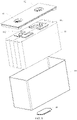
- FIG. 2 is a first schematic structural diagram of a battery disclosed in an embodiment of this application.
- FIG. 3 is an exploded view of FIG. 2 .
- FIG. 4 is a schematic structural diagram of a battery cell in FIG. 3 , with a pressure relief mechanism located at the top.
- FIG. 5 is a schematic structural diagram of a battery cell in FIG. 3 , with a pressure relief mechanism located at the bottom.
- FIG. 6 is a second schematic structural diagram of a battery disclosed in an embodiment of this application.
- FIG. 7 is a schematic structural diagram of portion A in FIG. 6 .
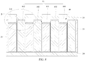
- FIG. 8 is a third schematic structural diagram of a battery disclosed in an embodiment of this application.
- FIG. 9 is a schematic structural diagram of portion B in FIG. 8 .
- FIG. 10 is a fourth schematic structural diagram of a battery disclosed in an embodiment of this application.
- FIG. 11 is a schematic structural diagram of portion C in FIG. 10 .
- the battery 1 includes a plurality of battery cells 10, where at least one of the battery cells 10 is provided with a pressure relief mechanism 14, and optionally, each battery cell 10 is provided with a pressure relief mechanism 14.
- the pressure relief mechanism 14 is configured to actuate release of internal pressure of the battery cell 10 when the internal pressure or internal temperature of the battery cell 10 reaches a threshold; and a protective box 20, where the protective box 20 is configured to protect the plurality of battery cells 10, and the protective box 20 is provided with a guiding channel 40, where the guiding channel 40 is configured to guide emissions released from the pressure relief mechanism 14; where the plurality of battery cells 10 include a first battery cell 101 and a second battery cell 102 that are arranged adjacently, the first battery cell 101 includes a pressure relief end at which the pressure relief mechanism 14 is provided, and the pressure relief end of the first battery cell 101 is staggered with one end of the second battery cell 102 that is close to the pressure relief end in a direction away from the guiding channel 40, so as to increase a volume of the guiding channel 40.
- the battery 1 includes a plurality of battery cells 10, where the battery cell 10 may have a structure well known to persons skilled in the art.
- the battery cell 10 in the application may include a lithium-ion secondary battery, a lithium-ion primary battery, a lithiumsulfur battery, a sodium lithium-ion battery, a sodium-ion battery, a magnesium-ion battery, or the like. This is not limited in this embodiment of this application.
- the battery cell 10 may be of a cylindrical shape, a flat shape, a cuboid shape, or other shapes. This is not limited in this embodiment of this application either.
- the battery cells 10 are typically divided into three types by packaging method: cylindrical battery cells, square battery cells, and soft pack battery cells. This is not limited in this embodiment of this application either.
- the battery cell 10 typically includes an electrode assembly 11 and an electrolyte (not shown).
- the electrode assembly 11 includes a positive electrode plate, a negative electrode plate, and a separator disposed between the positive electrode plate and the negative electrode plate. Operation of the battery cell 10 mainly relies on migration of metal ions between the positive electrode plate and the negative electrode plate.
- the positive electrode plate includes a positive electrode current collector and a positive electrode active substance layer. The positive electrode active substance layer is applied on a surface of the positive electrode current collector. An electrode current collector uncoated with the positive electrode active substance layer bulges out of an electrode current collector coated with the positive electrode active substance layer, and the electrode current collector uncoated with the positive electrode active substance layer is used as a positive tab 111.
- a material of the positive electrode current collector may be aluminum, and the positive electrode active substance may be lithium cobalt oxide, lithium iron phosphate, ternary lithium, lithium manganate oxide, or the like.
- the negative electrode plate includes a negative electrode current collector and a negative electrode active substance layer. The negative electrode active substance layer is applied on a surface of the negative electrode current collector. An electrode current collector uncoated with the negative electrode active substance layer bulges out of an electrode current collector coated with the negative electrode active substance layer, and the electrode current collector uncoated with the negative electrode active substance layer is used as a negative tab 112.
- a material of the negative electrode current collector may be copper, and the negative electrode active substance may be carbon, silicon, or the like.
- a material of the separator may be polypropylene (PP) or polyethylene (PE), or the like.
- the electrode assembly 11 may have a wound structure or a laminated structure, and the number of the electrode assembly 11 may be one or more. This is not specifically limited in this embodiment of this application.
- the battery cell 10 further includes a housing 15.
- the electrode assembly 11 and the electrolyte are both sealed in the housing 15.
- the housing 15 may be a hollow cuboid, cube, or cylinder.
- a material of the housing 15 may be aluminum or steel and alloys thereof, or plastic, or aluminum-plastic film.
- the housing 15 is also provided with a positive electrode terminal 12 and a negative electrode terminal 13, where the positive tab 111 is electrically connected to the positive electrode terminal 12, and the negative tab 112 is electrically connected to the negative electrode terminal 13, so as to output electrical energy.
- the housing 15 is also provided with the pressure relief mechanism 14.
- the pressure relief mechanism 14 may be disposed in any position of the housing 15. For example, the pressure relief mechanism 14 may be disposed on the top (as shown in FIG.
- the pressure relief mechanism 14 may be disposed between the positive electrode terminal 12 and the negative electrode terminal 13. This is not specifically limited in this embodiment of this application, as long as the internal pressure of the battery cells 10 can be released.
- the pressure relief mechanism 14 means a component or part that can actuate release of internal pressure of the battery cell 10 when the internal pressure or internal temperature of the battery cell reaches a threshold.
- the pressure relief mechanism 14 may specifically take a form of an explosion-proof valve, a gas valve, a pressure relief valve, a safety valve, or the like, and may specifically use a pressure sensitive or temperature sensitive component or structure. To be specific, when internal pressure or temperature of the battery cell 10 reaches the threshold, the pressure relief mechanism 14 performs an action or a weak structure provided in the pressure relief mechanism 14 is destroyed, thereby forming an opening or channel for relief of the internal pressure.
- the threshold in this application may be a pressure threshold or a temperature threshold. The threshold varies according to different design requirements.
- the threshold may be designed or determined based on the internal pressure or internal temperature of a battery cell 10 that is considered to be dangerous or at risk of being out of control.
- the threshold may depend on, for example, materials used for one or more of the positive electrode plate, negative electrode plate, electrolyte, and separator in the battery cell 10.
- Actuate means that the pressure relief mechanism 14 implements an action or is activated to a given state, so that the internal pressure of the battery cell 10 can be relieved.
- the action implemented by the pressure relief mechanism 14 may include but is not limited to, for example, cracking, breaking, tearing, or opening at least part of the pressure relief mechanism 14.
- When the pressure relief mechanism 14 is actuated high-pressure and high-temperature substances inside the battery cell are released from an actuated part as emissions. In this way, the battery cell 10 can discharge its pressure under a condition of controllable pressure or temperature, thereby avoiding more serious potential accidents.
- the emissions from the battery cell 10 mentioned in this application include but are not limited to: electrolyte, fragments of positive and negative electrode plates and separator because of dissolution or breaking, high-temperature and high-pressure gas and flames generated by reactions, and the like.
- the high-temperature and high-pressure emissions are released toward a side of the battery cell at which the pressure relief mechanism 14 is provided, and may be more specifically released toward a region where the pressure relief mechanism 14 is actuated.
- the strength and destructive power of such emissions are probably great, even great enough to break one or more parts in that direction.
- the plurality of battery cells 10 are arranged side by side, and the plurality of battery cells 10 are connected in series and parallel as predetermined through a bus component (not shown). In this way, a current produced by the battery cells 10 can be derived through the bus component to supply electric power to an apparatus.
- the plurality of battery cells 10 may be divided into a plurality of groups, and each group of battery cells 10 is separately packaged to form a battery module, and a plurality of battery modules are packaged to form the battery 1.
- the plurality of battery cells 10 may alternatively be directly packaged to form the battery 1.
- Forms of packaging of the battery 1 are not limited in this embodiment of this application.
- a plurality of prismatic cells may be directly packaged in the protective box 20 to form the battery 1.
- the protective box 20 may include a protective plate 21, four side plates 23, and a base plate 24, where the protective plate 21, the four side plates 23, and the base plate 24 are connected and surround the outer sides of the plurality of battery cells 10.
- a material of the protective box 20 may be metal, plastic, or the like.
- the guiding channel 40 is formed inside the protective box 20, to prevent the emissions from being released out of the protective box 20, that is, to prevent the emissions from causing harm to a surrounding environment and a human user when the battery 1 ruptures.
- the battery 1 has an arrangement direction X, a width direction Y, and a height direction Z, where the arrangement direction X, the width direction Y and the height direction Z are perpendicular to each other.
- the pressure relief mechanism 14 may be provided at any end of the battery cell 10 in the height direction Z or at any end in the width direction Y.
- the number of guiding channels 40 may be one or more.
- the plurality of battery cells 10 include at least two battery cells 10 that are staggered.
- the pressure relief mechanism 14 of the first battery cell 101 is provided at the top of the first battery cell 101 in the height direction Z
- the top of the first battery cell 101 in the height direction Z is a pressure relief end of the first battery cell 101
- the pressure relief mechanism 14 of the second battery cell 102 can be provided at any end of the second battery cell 102 in the height direction Z or any end in the width direction Y.
- the second battery cell 102 may be provided with no pressure relief mechanism 14.
- first battery cell 101 and the second battery cell 102 are staggered means that the top of the first battery cell 101 in the height direction Z and away from the guiding channel 40 is staggered with respect to the top of the second battery cell 102 in the height direction Z.
- the increased part of volume of the guiding channel 40 is surrounded by the following wall surfaces: the top surface of the first battery cell 101 and two side surfaces of two second battery cells 102 adjacent to the first battery cell 101, namely, the portion filled with oblique broken lines in FIG. 7 , FIG. 9 , and FIG. 11 .
- the increased part of volume of the guiding channel 40 is surrounded by the following surfaces: the top surface of the first battery cell 101, the side surface of the second battery cell 102 adjacent to the first battery cell 101, and the inner surface of the side plate 23.
- a size of the increased part of volume of the guiding channel 40 may be adjusted by adjusting a height difference between the top of the first battery cell 101 in the height direction Z and the top of the second battery cell 102 in the height direction Z.
- the battery 1 further includes another guiding channel 40.
- the pressure relief mechanism 14 of the second battery cell 102 is provided at one end of the second battery cell 102 in the width direction Y. That the first battery cell 101 and the second battery cell 102 are staggered may further include that the second battery cell 102 is staggered with respect to the first battery cell 101 in the width direction Y, so as to increase the volume of the guiding channel 40.
- the first battery cell 101 and the second battery cell 102 are staggered, as long as the volume of any one or more of the guiding channels 40 can be increased.
- the volume of the guiding channel 40 is increased to allow passage of a larger volume of emissions.
- the battery 1 has a larger relief buffer space in the protective box 20, and offers better safety performance.
- the bus component and the pressure relief mechanism 14 of the battery cell 10 may be located at the same end of the battery cell 10, or at different ends of the battery cell 10.
- the pressure relief mechanism 14 of the first battery cell 101 is located at the top in the height direction Z, and the bus component is disposed at the top of the first battery cell 101 in the height direction Z.
- this embodiment does not limit a position of the pressure relief mechanism 14 of the secondary battery cell 102.
- the battery 1 provided in this embodiment has at least the guiding channel 40 provided at the top of the first battery cell 101.
- the protective box 20 includes a protective plate 21, the protective plate 21 is spaced apart from the plurality of battery cells 10, and the guiding channel 40 is formed between the protective plate 21 and the plurality of battery cells 10.
- the protective plate 21 is provided with a recess 211, and the recess 211 is configured to increase the volume of the guiding channel 40.
- the recess 211 is formed by recessing the protective plate 21 in a direction away from the plurality of battery cells 10.
- the recess 211 has an inner chamber, and the inner chamber is configured to communicate with the guiding channel 40.
- the protective plate 21 is plate-shaped, and the recess 211 is recessed toward a side that faces away from the battery cell 10. In this way, the protective plate 21 is recessed toward the battery cell 10 to form the recess 211, the inner chamber of the recess 211 communicates with the guiding channel 40, and the volume of the guiding channel 40 further increases.
- the increased part is the inner chamber of the recess 211, namely, the portion filled with crossed broken lines, as shown in FIG. 9 and FIG. 11 . This allows passage of a larger volume of emissions, further improving the relief buffer space and safety performance of the battery 1.
- the recess 211 may be arranged opposite any battery cell 10.
- the number of recesses 211 may be one or more. This is not limited in this embodiment.
- the recess 211 may be arranged opposite a battery cell 10 that produces a large amount of gas or has a larger volume of emissions to release.
- the recess 211 is opposite the first battery cell 101.
- three parts of the guiding channel 40 may correspond to the first battery cell 101, which are a zone enclosed by the top surface of the first battery cell 101 and two side surfaces of the two second battery cells 102 adjacent to the first battery cell 101 (the portion filled with oblique broken lines in FIG. 7 , FIG. 9 , and FIG. 11 ), the guiding channel 40, and the inner chamber of the recess 211 (the portion filled with crossed broken lines in FIG. 9 and FIG. 11 ).
- the guiding channel 40 at the position corresponding to the first battery cell 101 has a larger space, and the emissions can smoothly enter the guiding channel 40. This reduces an impact of the emissions on an inner wall of the guiding channel 40, ensuring a better safety performance of the battery 1.
- the pressure relief mechanisms 14 of all battery cells 10 may all be located at the top in the height direction Z.
- the battery 1 is provided with one guiding channel 40, and the battery 1 has a relatively compact structure.
- the bus component and the pressure relief mechanism 14 of the first battery cell 101 may both be located at the bottom of the first battery cell 101 in the height direction Z or any end in the width direction Y. This structure is similar to that in the foregoing embodiment. Details are not described herein again.
- FIG. 12 is a fifth schematic structural diagram of a battery according to an embodiment of this application.
- FIG. 13 is a schematic structural diagram of portion D in FIG. 12 .
- the pressure relief mechanism 14 of the first battery cell 101 is located at the bottom in the height direction Z, and the bus component is disposed at the top of the first battery cell 101 in the height direction Z.
- this embodiment does not limit a position of the pressure relief mechanism 14 of the secondary battery cell 102.
- the pressure relief mechanism 14 of the second battery cell 102 may be provided at the bottom or top of the second battery cell 102 in the height direction Z.
- the battery 1 provided in this embodiment has at least the guiding channel 40 provided at the bottom of the first battery cell 101.
- the protective box 20 further includes a supporting plate 22.
- the supporting plate 22 is located at the bottom of the first battery cell 101 in the height direction Z, and is attached to the plurality of battery cells 10.
- the guiding channel 40 is provided on one side of the supporting plate 22 away from the plurality of battery cells 10. In other words, the guiding channel 40 is formed between the supporting plate 22 and the base plate 24 of the protective box 20, to prevent the emissions from being released out of the protective box 20.
- the supporting plate 22 is provided with through holes 221 for passage of the emissions, and the through holes 221 communicate with the guiding channel 40.
- the through hole 221 may be arranged opposite the pressure relief mechanism 14 of the first battery cell 101, helping emissions to enter the guiding channel 40 directly through the through hole 221, allowing smoother release of the emissions.
- the shape of the through hole 221 is adapted to the shape of the pressure relief mechanism 14.
- the through hole 221 may be a round hole, a square hole, and an oblong hole.
- bottoms of the first battery cell 101 and the second battery cell 102 in the height direction Z may be flush or staggered, as long as the guiding channel 40 can be formed at the position corresponding to the first battery cell 101.
- the bottom of the first battery cell 101 in the height direction Z may be staggered with respect to the bottom of the second battery cell 102 in the height direction Z, and the bottom of the first battery cell 101 in the height direction Z is located between two ends of the second battery cell 102.
- This increases the volume of the guiding channel 40, so that the battery 1 has a larger relief buffer space in the protective box 20, which allows passage of a larger volume of emissions, ensuring better safety performance of the battery 1.
- the height difference between the bottom of the first battery cell 101 in the height direction Z and the bottom of the second battery cell 102 in the height direction Z is directly proportional to the volume increase of the guiding channel 40.
- the volume increase of the guiding channel 40 rises with the height difference.
- the height difference can be set as required.
- the zone of the supporting plate 22 corresponding to the second battery cell 102 may be in contact with the base plate.
- the first battery cell 101 and the second battery cell 102 are staggered at the bottom in the height direction Z, so that the guiding channel 40 is formed under the first battery cell 101.
- the height difference between the bottom of the first battery cell 101 in the height direction Z and the bottom of the second battery cell 102 in the height direction Z may be increased.
- the protective box 20 is further provided with a supporting plate 22, where the supporting plate 22 is configured to support the plurality of battery cells 10.
- the plurality of battery cells 10 can be directly connected to the base plate 24 of the protective box 20, where the base plate 24 is configured to support the plurality of battery cells 10.
- the surface, in contact with the plurality of battery cells 10, of the supporting plate 22 or base plate 24 is flat (as shown in FIG. 6 and FIG. 8 ).
- the surface, in contact with the plurality of battery cells 10, of the supporting plate 22 or base plate 24 is concave or convex surface (as shown in FIG. 10 and FIG. 12 ).
- the first battery cell 101 and the second battery cell 102 are staggered at the bottom in the height direction Z
- a recessed supporting portion is provided on the base plate 24, and the bottom of the first battery cell 101 in the height direction Z can extend into and be supported in the supporting portion, so that the bottom of the first battery cell 101 is inserted into the supporting portion, and the bottom of the first battery cell 101 is fixed relative to the base plate 24.
- the first battery cell 101 is comparatively stable, and the battery 1 is well fastened.
- the bottom surface of the first battery cell 101 is in contact with the bottom surface of the supporting portion, and the side surface of the first battery cell 101 is in contact with the side surface of the supporting portion.
- the inner surface of the supporting portion forms a limit to the bottom of the first battery cell 101.
- the base plate 24 when the base plate 24 is provided with the recessed supporting portion, the base plate 24 is also provided with a corresponding protruding portion(s), where the second battery cell 102 may be supported by the protruding portion.
- the protruding portion may be fastened to or integrally formed with the base plate 24.
- the base plate 24 may be a plate structure, the protruding portion is connected to the base plate 24, and the protruding portion forms a concave-convex supporting surface jointly with the base plate 24. In this way, the base plate 24 is highly strong. Moreover, an outer surface of the base plate 24 is flat, facilitating mounting of the battery 1 to an apparatus.
- a principle of clamping the supporting plate 22 to the battery cell 10 is similar to a principle of clamping the base plate to the battery cell 10. Details are not described herein again.
- FIG. 14 is a sixth schematic structural diagram of a battery according to an embodiment of this application.
- the battery 1 further includes an elastic member 30, where the elastic member 30 is connected to the base plate 24, and is configured to support the battery cells 10. This can improve shock absorption and impact resistance of the battery cells 10 and the battery 1.
- the elastic member 30 may be a spring, elastic rubber, or the like. This is not limited in this embodiment.
- Each battery cell 10 may be correspondingly provided with one elastic member 30, so as to buffer each battery cell 10 separately.
- an accommodating groove (not shown) is provided in the base plate 24, and the accommodating groove is configured to accommodate the elastic member 30.
- the elastic member 30 may elastically deform in the accommodating groove.
- the accommodating groove can play a guiding role to prevent skewing of the battery cell 10 because of skewing of the elastic member 30 during the deformation.
- the number of accommodating grooves may be less than the number of battery cells 10, so as to avoid strength of the base plate 24 being weakened by excessive accommodating grooves.
- the elastic member 30 is connected to the supporting plate 22. Details are not described herein again.
- the first battery cell 101 and the second battery cell 102 may be identical or different battery cells.
- being “identical” means that the first battery cell 101 and the second battery cell 102 are essentially the same in terms of chemical system, shape, size, volume, mass, energy density, and the like, and being “different” means that the first battery cell 101 and the second battery cell 102 have a significant difference in at least one of the chemical system, shape, size, volume, mass, energy density, and the like.
- an energy density of the first battery cell 101 is greater than an energy density of the second battery cell 102, where energy density means the amount of energy released by a battery per unit mass or unit volume, namely, gravimetric energy density or volumetric energy density.
- the energy density of the first battery cell 101 is 1.1 to 1.6 times the energy density of the second battery cell 102. With the energy density of the first battery cell 101 being greater than the energy density of the second battery cell 102, a larger volume of emissions is generated when the pressure relief mechanism 14 of the first battery cell 101 is actuated. Increasing the volume of the guiding channel 40 opposite the first battery cell 101 helps release the emissions more smoothly.
- the first battery cell 101 may be a ternary lithium battery cell, specifically, for example, a lithium nickel manganese cobalt oxide (LiNiMnCoO 2 , NCM) battery cell or a lithium nickel cobalt aluminium oxide (LiNiCoAlO 2 , NCA) battery cell
- the second battery cell 102 may be a lithium iron phosphate (LiFePO 4 , LFP) battery cell or a lithium cobalt oxide (LiCoO 2 ) battery cell.
- the number of first battery cells 101 and that of second battery cells 102 are not limited in the embodiments of this application.
- the number of first battery cells 101 and that of second battery cells 102 may be set as required.
- one first battery cell 101 and one second battery cell 102 may be provided.
- One first battery cell 101 and a plurality of second battery cells 102 may be provided.
- a plurality of first battery cells 101 and a plurality of second battery cells 102 may be provided.
- the first battery cells 101 and the second battery cells 102 are both provided in plurality, the first battery cells 101 and the second battery cells 102 are arranged alternately with n first battery cells 101 followed by m second battery cells 102, where n ⁇ 1, m ⁇ 1, and n and m are both integers.
- this embodiment does not limit arrangements of the first battery cells 101 and the second battery cells 102.
- three first battery cells 101, two second battery cells 102, and four first battery cells 101 may be arranged in sequence.
- the first battery cells 101 and the second battery cells 102 may be arranged in alternate turn.
- a first battery cell 101 is adjacent to second battery cells 102 on both sides
- a second battery cell 102 is adjacent to first battery cells 101 on both sides.
- the first battery cells 101 with higher emissions and the second battery cells 102 with lower emissions are arranged alternately. This can avoid accumulation of excessive emissions in a particular zone of the guiding channel 40, facilitating an even distribution of the emissions of the first battery cell 101 and the emissions of the second battery cell 102 in the guiding channel 40, so that stress is evenly distributed in the guiding channel 40, ensuring good safety performance of the battery 1.
- An embodiment of this application further provides a preparation method of battery 1.
- the method is used for preparing the battery 1 and includes:
- An embodiment of this application further provides a preparation device of battery 1, used for preparing the battery 1, and including: a battery cell preparation module, configured to prepare the plurality of battery cells 10, where at least one of the battery cells 10 is provided with a pressure relief mechanism 14, and the plurality of battery cells 10 include a first battery cell 101 and a second battery cell 102 that are arranged adjacently; a protective box preparation module, configured to prepare the protective box 20; an assembly module, configured to install the plurality of battery cells 10 in the protective box 20, where a pressure relief end of the first battery cell 101 is staggered with one end of the second battery cell 102 that is close to the pressure relief end.
- a battery cell preparation module configured to prepare the plurality of battery cells 10, where at least one of the battery cells 10 is provided with a pressure relief mechanism 14, and the plurality of battery cells 10 include a first battery cell 101 and a second battery cell 102 that are arranged adjacently
- a protective box preparation module configured to prepare the protective box 20
- an assembly module configured to install the plurality of battery cells 10 in
- the battery cell preparation module, protective box preparation module, and assembly module may be separate from each other, or each be a component of the preparation device of battery. This is not limited in this embodiment.
- the battery cells 10 and the protective box 20 are prepared by the battery cell preparation module and the protective box preparation module, and the guiding channel 40 is formed in the protective box 20.
- all battery cells 10 may be arranged side by side, so that the assembly module may accommodate the plurality of battery cells 10 arranged side by side in the protective box 20. Then the pressure relief end of the first battery cell 101 is staggered with the one end of the second battery cell 102 that is close to the pressure relief end. This increases the volume of the guiding channel 40, providing a larger space for accommodating emissions in the guiding channel 40. In this way, the battery 1 has a larger relief buffer space and offers better safety performance.
Landscapes
- Chemical & Material Sciences (AREA)
- Chemical Kinetics & Catalysis (AREA)
- Electrochemistry (AREA)
- General Chemical & Material Sciences (AREA)
- Engineering & Computer Science (AREA)
- Materials Engineering (AREA)
- Manufacturing & Machinery (AREA)
- Battery Mounting, Suspending (AREA)
Abstract
Description
- This application relates to the field of battery technologies, and in particular, to a battery, an apparatus using a battery, and a preparation method and preparation device of battery.
- Apparatuses such as automobiles, electric bicycles, ships, and energy storage cabinets include batteries. The batteries provide electrical energy for the apparatuses.
- A battery includes a plurality of battery cells and a box body. The plurality of battery cells are arranged in sequence, and the box body surrounds the outside of the plurality of battery cells and protects the plurality of battery cells. The box body is provided with positive and negative electrodes, and each battery cell is connected to the positive and negative electrodes. When the battery is working, active materials and electrolyte inside the battery cells react chemically with each other to provide electrical energy for a load. A battery cell is provided with a pressure relief mechanism that is configured to actuate release of internal pressure of the battery cell when the internal pressure or internal temperature of the battery cell reaches a threshold. Emissions of the battery cells released through the pressure relief mechanism enter a space formed between the battery cells and the box body.
- However, when some of the battery cells in the battery generate a large amount of gas, both volume and pressure of the emissions are large, likely to result in cracking of the box body and poorer safety performance of the battery.
- Embodiments of this application provide a battery, an apparatus using a battery, and a preparation method and preparation device of a battery. Such battery can accommodate more emissions and offer better safety performance.
- To achieve the foregoing objective, the embodiments of this application provide the following technical solutions:
- A first aspect of the embodiments of this disclosure provides a battery, including a plurality of battery cells, where at least one of the battery cells is provided with a pressure relief mechanism, and the pressure relief mechanism is configured to actuate release of internal pressure of the battery cell when the internal pressure or internal temperature of the battery cell reaches a threshold; and a protective box, where the protective box is configured to protect the plurality of battery cells, and the protective box is provided with a guiding channel, where the guiding channel is configured to guide emissions released from the pressure relief mechanism; where the plurality of battery cells include a first battery cell and a second battery cell that are arranged adjacently, the first battery cell includes a pressure relief end at which the pressure relief mechanism is provided, and the pressure relief end of the first battery cell is staggered with one end of the second battery cell that is close to the pressure relief end, in a direction away from the guiding channel, so as to increase a volume of the guiding channel.
- In some optional embodiments, the protective box includes a protective plate, the protective plate is spaced apart from the plurality of battery cells, and the guiding channel is formed between the protective plate and the plurality of battery cells; and the protective plate is provided with a recess, the recess is configured to increase the volume of the guiding channel, the recess is formed by recessing the protective plate in a direction away from the plurality of battery cells, the recess has an inner chamber, and the inner chamber is configured to communicate with the guiding channel.
- In some optional embodiments, the recess is opposite the first battery cell.
- In some optional embodiments, the protective box includes a supporting plate, the supporting plate is attached to the plurality of battery cells, and the guiding channel is provided on one side of the supporting plate away from the plurality of battery cells; and the supporting plate is provided with through holes for the emissions to pass through, where the through holes communicate with the guiding channel.
- In some optional embodiments, an energy density of the first battery cell is greater than an energy density of the second battery cell.
- In some optional embodiments, an energy density of the first battery cell is 1.1 to 1.6 times the energy density of the second battery cell.
- In some optional embodiments, the first battery cell and the second battery cell are both provided in plurality, and the first battery cells and the second battery cells are arranged alternately with n first battery cells followed by m second battery cells, n ≥ 1, and m ≥ 1.
- The battery provided in the embodiments of this application has the following advantages over conventional technology: the battery includes a plurality of battery cells and a protective box, where the plurality of battery cells are disposed in the protective box so that the protective box can protect the plurality of battery cells. The plurality of battery cells include a first battery cell and a second battery cell, and a pressure relief end of the first battery cell is staggered with one end of the second battery cell that is close to the pressure relief end, in a direction away from the guiding channel, so as to increase a volume of the guiding channel. This allows for a larger relief buffer space in the protective box, and therefore, the protective box can accommodate more emissions, ensuring better safety performance of the battery.
- A second aspect of the embodiments of this disclosure provides an apparatus using a battery, including the battery according to the first aspect, where the battery provides electrical energy for the apparatus.
- A third aspect of the embodiments of this disclosure provides a preparation method of a battery, used for preparing the battery according to the first aspect, and including: providing a plurality of battery cells, where at least one of the battery cells is provided with a pressure relief mechanism, and the plurality of battery cells comprise a first battery cell and a second battery cell that are arranged adjacently; providing a protective box; installing the plurality of battery cells in the protective box, where the protective box is provided with a guiding channel; and staggering a pressure relief end of the first battery cell and one end of the second battery cell that is close to the pressure relief end.
- A fourth aspect of the embodiments of this disclosure provides a preparation device of a battery, used for preparing the battery according to the first aspect, and including: a battery cell preparation module, configured to prepare the plurality of battery cells, where at least one of the battery cells is provided with a pressure relief mechanism, and the plurality of battery cells include a first battery cell and a second battery cell that are arranged adjacently; a protective box preparation module, configured to prepare the protective box; an assembly module, configured to install the plurality of battery cells in the protective box, where a pressure relief end of the first battery cell is staggered with one end of the second battery cell that is close to the pressure relief end.
- To describe the technical solutions in the embodiments of this application more clearly, the following briefly describes the accompanying drawings required for describing the embodiments of this application. Apparently, the accompanying drawings in the following description show merely some embodiments of this application, and a person of ordinary skill in the art may still derive other drawings from the accompanying drawings without creative efforts.
-
FIG. 1 is a schematic structural diagram of an apparatus using a battery according to an embodiment of this application; -
FIG. 2 is a first schematic structural diagram of a battery according to an embodiment of this application; -
FIG. 3 is an exploded view ofFIG. 2 ; -
FIG. 4 is a schematic structural diagram of a battery cell inFIG. 3 with a pressure relief mechanism located at the top; -
FIG. 5 is a schematic structural diagram of a battery cell inFIG. 3 , with a pressure relief mechanism located at the bottom; -
FIG. 6 is a second schematic structural diagram of a battery according to an embodiment of this application; -
FIG. 7 is a schematic structural diagram of portion A inFIG. 6 ; -
FIG. 8 is a third schematic structural diagram of a battery according to an embodiment of this application; -
FIG. 9 is a schematic structural diagram of portion B inFIG. 8 ; -
FIG. 10 is a fourth schematic structural diagram of a battery according to an embodiment of this application; -
FIG. 11 is a schematic structural diagram of portion C inFIG. 10 ; -
FIG. 12 is a fifth schematic structural diagram of a battery according to an embodiment of this application; -
FIG. 13 is a schematic structural diagram of portion D inFIG. 12 ; and -
FIG. 14 is a sixth schematic structural diagram of a battery according to an embodiment of this application. - In the accompanying drawings, the figures are not drawn to scale.
- Reference signs are described as follows:
- 1. battery
- 10. battery cell; 101. first battery cell; 102. second battery cell; 11. electrode assembly; 111. positive tab; 112. negative tab; 12. positive electrode terminal; 13. negative electrode terminal; 14. pressure relief mechanism; 15. housing;
- 20. protective box; 21. protective plate; 211. recess; 22. supporting plate; 221. through hole; 23. side plate; 24. base plate;
- 30. elastic member;
- 40. guiding channel;
- 50. vehicle; 51. drive mechanism; 52. control mechanism.
- The following further describes the embodiments of this application in detail with reference to the accompanying drawings and examples. The detailed description and accompanying drawings of the following embodiments are used to illustrate the principle of this application, but are not intended to limit the scope of this application, meaning that this application is not limited to the described embodiments.
- In the descriptions of this application, it should be noted that, unless otherwise stated, "plurality" means two or more; and the orientations or positional relationships indicated by the terms "upper", "lower", "left", "right", "inside", "outside", and the like are merely intended to help the descriptions of this application and simplify the descriptions other than indicate or imply that the apparatuses or components must have specific orientations, or be constructed and manipulated with specific orientations, and therefore shall not be construed as limitations on this application. In addition, the terms "first", "second", and "third" are merely intended for a purpose of description, and shall not be understood as an indication or implication of relative importance. "Vertical" means being vertical with an allowable range of error other than being strictly vertical. "Parallel" means being parallel with an allowable range of error other than being strictly parallel.
- The orientation terms appearing in the following description all indicate directions shown in the figures, and do not limit the specific structure of the application. In the descriptions of this application, it should be further noted that unless otherwise specified and defined explicitly, the terms "installment", "link", "connection", and "attachment" should be understood in their general senses. For example, the terms may be a fixed connection, a detachable connection, or an integrated connection, or may be a direct connection or an indirect connection through an intermediate medium. A person of ordinary skill in the art can understand specific meanings of these terms in this application as appropriate to specific situations.
- In conventional technology, a battery includes a plurality of battery cells arranged side by side and a protective box surrounding the battery cells, with a guiding channel formed in the protective box. As such, when a pressure relief mechanism of a battery cell is actuated, emissions in the battery cell are released to the guiding channel through the pressure relief mechanism. However, when some of the battery cells generate a large amount of emissions, volume and pressure of the emissions are both large, likely to result in cracking of the protective box and poorer safety performance of the battery.
- In view of this, the plurality of battery cells provided in the embodiments of this application include at least one first battery cell and one secondary battery cell that are staggered with each other, and one of the first battery cell and the second battery cell is displaced in a direction leaving the guiding channel. This increases a volume of the guiding channel, facilitating a larger relief buffer space in the protective box. Therefore, the protective box allows passage of a larger volume of emissions, ensuring better safety performance of the battery.
-
FIG. 1 is a schematic structural diagram of an apparatus using a battery provided in an embodiment of this application. - Referring to
FIG. 1 , this embodiment of this application provides an apparatus using a battery. The apparatus may be a movable device such as avehicle 50, a ship, or a small aircraft, or an immovable device capable of providing electrical energy, such as an energy storage cabinet. Using thevehicle 50 as an example, thevehicle 50 may be a new energy vehicle, where the new energy vehicle may be a battery electric vehicle, a hybrid electric vehicle or a rangeextended vehicle. Thevehicle 50 may include adrive mechanism 51, acontrol mechanism 52, and abattery 1, where thecontrol mechanism 52 is electrically connected to thedrive mechanism 51, and configured to control start and stop of thedrive mechanism 51 as required, so as to drive or park thevehicle 50. Thebattery 1 is electrically connected to thecontrol mechanism 52, and configured to provide electrical energy for thecontrol mechanism 52. Power consuming components in thevehicle 50 may also include audio devices and the like. -
FIG. 2 is a first schematic structural diagram of a battery disclosed in an embodiment of this application.FIG. 3 is an exploded view ofFIG. 2 .FIG. 4 is a schematic structural diagram of a battery cell inFIG. 3 , with a pressure relief mechanism located at the top.FIG. 5 is a schematic structural diagram of a battery cell inFIG. 3 , with a pressure relief mechanism located at the bottom.FIG. 6 is a second schematic structural diagram of a battery disclosed in an embodiment of this application.FIG. 7 is a schematic structural diagram of portion A inFIG. 6 .FIG. 8 is a third schematic structural diagram of a battery disclosed in an embodiment of this application.FIG. 9 is a schematic structural diagram of portion B inFIG. 8 .FIG. 10 is a fourth schematic structural diagram of a battery disclosed in an embodiment of this application.FIG. 11 is a schematic structural diagram of portion C inFIG. 10 . - Referring to
FIG. 2 to FIG. 11 , in some optional embodiments, thebattery 1 includes a plurality ofbattery cells 10, where at least one of thebattery cells 10 is provided with apressure relief mechanism 14, and optionally, eachbattery cell 10 is provided with apressure relief mechanism 14. Thepressure relief mechanism 14 is configured to actuate release of internal pressure of thebattery cell 10 when the internal pressure or internal temperature of thebattery cell 10 reaches a threshold; and aprotective box 20, where theprotective box 20 is configured to protect the plurality ofbattery cells 10, and theprotective box 20 is provided with a guidingchannel 40, where the guidingchannel 40 is configured to guide emissions released from thepressure relief mechanism 14; where the plurality ofbattery cells 10 include afirst battery cell 101 and asecond battery cell 102 that are arranged adjacently, thefirst battery cell 101 includes a pressure relief end at which thepressure relief mechanism 14 is provided, and the pressure relief end of thefirst battery cell 101 is staggered with one end of thesecond battery cell 102 that is close to the pressure relief end in a direction away from the guidingchannel 40, so as to increase a volume of the guidingchannel 40. - Specifically, referring to
FIG. 2 to FIG. 5 , thebattery 1 includes a plurality ofbattery cells 10, where thebattery cell 10 may have a structure well known to persons skilled in the art. Thebattery cell 10 in the application may include a lithium-ion secondary battery, a lithium-ion primary battery, a lithiumsulfur battery, a sodium lithium-ion battery, a sodium-ion battery, a magnesium-ion battery, or the like. This is not limited in this embodiment of this application. Thebattery cell 10 may be of a cylindrical shape, a flat shape, a cuboid shape, or other shapes. This is not limited in this embodiment of this application either. Thebattery cells 10 are typically divided into three types by packaging method: cylindrical battery cells, square battery cells, and soft pack battery cells. This is not limited in this embodiment of this application either. - As shown in
FIG. 4 andFIG. 5 , thebattery cell 10 typically includes anelectrode assembly 11 and an electrolyte (not shown). Theelectrode assembly 11 includes a positive electrode plate, a negative electrode plate, and a separator disposed between the positive electrode plate and the negative electrode plate. Operation of thebattery cell 10 mainly relies on migration of metal ions between the positive electrode plate and the negative electrode plate. The positive electrode plate includes a positive electrode current collector and a positive electrode active substance layer. The positive electrode active substance layer is applied on a surface of the positive electrode current collector. An electrode current collector uncoated with the positive electrode active substance layer bulges out of an electrode current collector coated with the positive electrode active substance layer, and the electrode current collector uncoated with the positive electrode active substance layer is used as apositive tab 111. Using the lithium-ion battery as an example, a material of the positive electrode current collector may be aluminum, and the positive electrode active substance may be lithium cobalt oxide, lithium iron phosphate, ternary lithium, lithium manganate oxide, or the like. The negative electrode plate includes a negative electrode current collector and a negative electrode active substance layer. The negative electrode active substance layer is applied on a surface of the negative electrode current collector. An electrode current collector uncoated with the negative electrode active substance layer bulges out of an electrode current collector coated with the negative electrode active substance layer, and the electrode current collector uncoated with the negative electrode active substance layer is used as anegative tab 112. A material of the negative electrode current collector may be copper, and the negative electrode active substance may be carbon, silicon, or the like. To ensure that no fuse blows as a large current flows, a plurality ofpositive tabs 111 are stacked together, and a plurality ofnegative tabs 112 are stacked together. A material of the separator may be polypropylene (PP) or polyethylene (PE), or the like. In addition, theelectrode assembly 11 may have a wound structure or a laminated structure, and the number of theelectrode assembly 11 may be one or more. This is not specifically limited in this embodiment of this application. - The
battery cell 10 further includes ahousing 15. Theelectrode assembly 11 and the electrolyte are both sealed in thehousing 15. Thehousing 15 may be a hollow cuboid, cube, or cylinder. A material of thehousing 15 may be aluminum or steel and alloys thereof, or plastic, or aluminum-plastic film. Thehousing 15 is also provided with apositive electrode terminal 12 and anegative electrode terminal 13, where thepositive tab 111 is electrically connected to thepositive electrode terminal 12, and thenegative tab 112 is electrically connected to thenegative electrode terminal 13, so as to output electrical energy. Thehousing 15 is also provided with thepressure relief mechanism 14. Thepressure relief mechanism 14 may be disposed in any position of thehousing 15. For example, thepressure relief mechanism 14 may be disposed on the top (as shown inFIG. 4 ), the bottom (as shown inFIG. 5 ), or a side (not shown) of thehousing 15, or thepressure relief mechanism 14 may be disposed between thepositive electrode terminal 12 and thenegative electrode terminal 13. This is not specifically limited in this embodiment of this application, as long as the internal pressure of thebattery cells 10 can be released. - The
pressure relief mechanism 14 means a component or part that can actuate release of internal pressure of thebattery cell 10 when the internal pressure or internal temperature of the battery cell reaches a threshold. Thepressure relief mechanism 14 may specifically take a form of an explosion-proof valve, a gas valve, a pressure relief valve, a safety valve, or the like, and may specifically use a pressure sensitive or temperature sensitive component or structure. To be specific, when internal pressure or temperature of thebattery cell 10 reaches the threshold, thepressure relief mechanism 14 performs an action or a weak structure provided in thepressure relief mechanism 14 is destroyed, thereby forming an opening or channel for relief of the internal pressure. The threshold in this application may be a pressure threshold or a temperature threshold. The threshold varies according to different design requirements. For example, the threshold may be designed or determined based on the internal pressure or internal temperature of abattery cell 10 that is considered to be dangerous or at risk of being out of control. Moreover, the threshold may depend on, for example, materials used for one or more of the positive electrode plate, negative electrode plate, electrolyte, and separator in thebattery cell 10. - "Actuate" mentioned in this application means that the
pressure relief mechanism 14 implements an action or is activated to a given state, so that the internal pressure of thebattery cell 10 can be relieved. The action implemented by thepressure relief mechanism 14 may include but is not limited to, for example, cracking, breaking, tearing, or opening at least part of thepressure relief mechanism 14. When thepressure relief mechanism 14 is actuated, high-pressure and high-temperature substances inside the battery cell are released from an actuated part as emissions. In this way, thebattery cell 10 can discharge its pressure under a condition of controllable pressure or temperature, thereby avoiding more serious potential accidents. The emissions from thebattery cell 10 mentioned in this application include but are not limited to: electrolyte, fragments of positive and negative electrode plates and separator because of dissolution or breaking, high-temperature and high-pressure gas and flames generated by reactions, and the like. The high-temperature and high-pressure emissions are released toward a side of the battery cell at which thepressure relief mechanism 14 is provided, and may be more specifically released toward a region where thepressure relief mechanism 14 is actuated. The strength and destructive power of such emissions are probably great, even great enough to break one or more parts in that direction. - The plurality of
battery cells 10 are arranged side by side, and the plurality ofbattery cells 10 are connected in series and parallel as predetermined through a bus component (not shown). In this way, a current produced by thebattery cells 10 can be derived through the bus component to supply electric power to an apparatus. - The plurality of
battery cells 10 may be divided into a plurality of groups, and each group ofbattery cells 10 is separately packaged to form a battery module, and a plurality of battery modules are packaged to form thebattery 1. Optionally, the plurality ofbattery cells 10 may alternatively be directly packaged to form thebattery 1. Forms of packaging of thebattery 1 are not limited in this embodiment of this application. - Using prismatic cells as an example, a plurality of prismatic cells may be directly packaged in the
protective box 20 to form thebattery 1. Theprotective box 20 may include aprotective plate 21, fourside plates 23, and abase plate 24, where theprotective plate 21, the fourside plates 23, and thebase plate 24 are connected and surround the outer sides of the plurality ofbattery cells 10. A material of theprotective box 20 may be metal, plastic, or the like. - The guiding
channel 40 is formed inside theprotective box 20, to prevent the emissions from being released out of theprotective box 20, that is, to prevent the emissions from causing harm to a surrounding environment and a human user when thebattery 1 ruptures. - As shown in
FIG. 3 , thebattery 1 has an arrangement direction X, a width direction Y, and a height direction Z, where the arrangement direction X, the width direction Y and the height direction Z are perpendicular to each other. - The
pressure relief mechanism 14 may be provided at any end of thebattery cell 10 in the height direction Z or at any end in the width direction Y. When thepressure relief mechanisms 14 of a plurality ofbattery cells 10 are located at different positions, the number of guidingchannels 40 may be one or more. - To increases a volume of the guiding
channel 40, the plurality ofbattery cells 10 include at least twobattery cells 10 that are staggered. Referring toFIG. 6 to FIG. 11 , using theguide channel 40 provided at the top of thefirst battery cell 101 in the height direction Z as an example, thepressure relief mechanism 14 of thefirst battery cell 101 is provided at the top of thefirst battery cell 101 in the height direction Z, the top of thefirst battery cell 101 in the height direction Z is a pressure relief end of thefirst battery cell 101, and thepressure relief mechanism 14 of thesecond battery cell 102 can be provided at any end of thesecond battery cell 102 in the height direction Z or any end in the width direction Y. Optionally, thesecond battery cell 102 may be provided with nopressure relief mechanism 14. In this case, that thefirst battery cell 101 and thesecond battery cell 102 are staggered means that the top of thefirst battery cell 101 in the height direction Z and away from the guidingchannel 40 is staggered with respect to the top of thesecond battery cell 102 in the height direction Z. In this way, the increased part of volume of the guidingchannel 40 is surrounded by the following wall surfaces: the top surface of thefirst battery cell 101 and two side surfaces of twosecond battery cells 102 adjacent to thefirst battery cell 101, namely, the portion filled with oblique broken lines inFIG. 7 ,FIG. 9 , andFIG. 11 . - It can be understood that when the
first battery cell 101 is adjacent to aside plate 23, the increased part of volume of the guidingchannel 40 is surrounded by the following surfaces: the top surface of thefirst battery cell 101, the side surface of thesecond battery cell 102 adjacent to thefirst battery cell 101, and the inner surface of theside plate 23. - A size of the increased part of volume of the guiding
channel 40 may be adjusted by adjusting a height difference between the top of thefirst battery cell 101 in the height direction Z and the top of thesecond battery cell 102 in the height direction Z. - It can be understood that when the
pressure relief mechanism 14 of thesecond battery cell 102 is not provided at the top along the height direction Z, thebattery 1 further includes another guidingchannel 40. For example, thepressure relief mechanism 14 of thesecond battery cell 102 is provided at one end of thesecond battery cell 102 in the width direction Y. That thefirst battery cell 101 and thesecond battery cell 102 are staggered may further include that thesecond battery cell 102 is staggered with respect to thefirst battery cell 101 in the width direction Y, so as to increase the volume of the guidingchannel 40. - In other words, when the
battery 1 is provided with a plurality of guidingchannels 40, thefirst battery cell 101 and thesecond battery cell 102 are staggered, as long as the volume of any one or more of the guidingchannels 40 can be increased. - In this embodiment of this application, the volume of the guiding
channel 40 is increased to allow passage of a larger volume of emissions. In this way, thebattery 1 has a larger relief buffer space in theprotective box 20, and offers better safety performance. - In some optional embodiments, the bus component and the
pressure relief mechanism 14 of thebattery cell 10 may be located at the same end of thebattery cell 10, or at different ends of thebattery cell 10. - When the bus component and the
pressure relief mechanism 14 of thebattery cell 10 are located at the same end of thebattery cell 10, still referring toFIG. 6 to FIG. 11 , thepressure relief mechanism 14 of thefirst battery cell 101 is located at the top in the height direction Z, and the bus component is disposed at the top of thefirst battery cell 101 in the height direction Z. In this case, this embodiment does not limit a position of thepressure relief mechanism 14 of thesecondary battery cell 102. In addition, thebattery 1 provided in this embodiment has at least the guidingchannel 40 provided at the top of thefirst battery cell 101. - Specifically, the
protective box 20 includes aprotective plate 21, theprotective plate 21 is spaced apart from the plurality ofbattery cells 10, and the guidingchannel 40 is formed between theprotective plate 21 and the plurality ofbattery cells 10. - To further improve the relief buffer space and safety performance of the
battery 1, referring toFIG. 8 to FIG. 11 , theprotective plate 21 is provided with arecess 211, and therecess 211 is configured to increase the volume of the guidingchannel 40. Therecess 211 is formed by recessing theprotective plate 21 in a direction away from the plurality ofbattery cells 10. Therecess 211 has an inner chamber, and the inner chamber is configured to communicate with the guidingchannel 40. - Specifically, the
protective plate 21 is plate-shaped, and therecess 211 is recessed toward a side that faces away from thebattery cell 10. In this way, theprotective plate 21 is recessed toward thebattery cell 10 to form therecess 211, the inner chamber of therecess 211 communicates with the guidingchannel 40, and the volume of the guidingchannel 40 further increases. The increased part is the inner chamber of therecess 211, namely, the portion filled with crossed broken lines, as shown inFIG. 9 andFIG. 11 . This allows passage of a larger volume of emissions, further improving the relief buffer space and safety performance of thebattery 1. - The
recess 211 may be arranged opposite anybattery cell 10. The number ofrecesses 211 may be one or more. This is not limited in this embodiment. - In some optional embodiments, the
recess 211 may be arranged opposite abattery cell 10 that produces a large amount of gas or has a larger volume of emissions to release. For example, therecess 211 is opposite thefirst battery cell 101. In this way, three parts of the guidingchannel 40 may correspond to thefirst battery cell 101, which are a zone enclosed by the top surface of thefirst battery cell 101 and two side surfaces of the twosecond battery cells 102 adjacent to the first battery cell 101 (the portion filled with oblique broken lines inFIG. 7 ,FIG. 9 , andFIG. 11 ), the guidingchannel 40, and the inner chamber of the recess 211 (the portion filled with crossed broken lines inFIG. 9 andFIG. 11 ). In this case, the guidingchannel 40 at the position corresponding to thefirst battery cell 101 has a larger space, and the emissions can smoothly enter the guidingchannel 40. This reduces an impact of the emissions on an inner wall of the guidingchannel 40, ensuring a better safety performance of thebattery 1. - In some optional embodiments, the
pressure relief mechanisms 14 of allbattery cells 10 may all be located at the top in the height direction Z. In this case, thebattery 1 is provided with one guidingchannel 40, and thebattery 1 has a relatively compact structure. - In some optional embodiments, the bus component and the
pressure relief mechanism 14 of thefirst battery cell 101 may both be located at the bottom of thefirst battery cell 101 in the height direction Z or any end in the width direction Y. This structure is similar to that in the foregoing embodiment. Details are not described herein again. - When the bus component and the
pressure relief mechanism 14 of thebattery cell 10 are located at different ends of thebattery cell 10, the structure is similar to that in the foregoing embodiment. Details are not described herein again. -
FIG. 12 is a fifth schematic structural diagram of a battery according to an embodiment of this application.FIG. 13 is a schematic structural diagram of portion D inFIG. 12 . - Referring to
FIG. 12 to FIG. 13 , thepressure relief mechanism 14 of thefirst battery cell 101 is located at the bottom in the height direction Z, and the bus component is disposed at the top of thefirst battery cell 101 in the height direction Z. In this case, this embodiment does not limit a position of thepressure relief mechanism 14 of thesecondary battery cell 102. For example, thepressure relief mechanism 14 of thesecond battery cell 102 may be provided at the bottom or top of thesecond battery cell 102 in the height direction Z. In this case, thebattery 1 provided in this embodiment has at least the guidingchannel 40 provided at the bottom of thefirst battery cell 101. - The
protective box 20 further includes a supportingplate 22. The supportingplate 22 is located at the bottom of thefirst battery cell 101 in the height direction Z, and is attached to the plurality ofbattery cells 10. The guidingchannel 40 is provided on one side of the supportingplate 22 away from the plurality ofbattery cells 10. In other words, the guidingchannel 40 is formed between the supportingplate 22 and thebase plate 24 of theprotective box 20, to prevent the emissions from being released out of theprotective box 20. - In order to release the emissions of the
first battery cell 101, the supportingplate 22 is provided with throughholes 221 for passage of the emissions, and the throughholes 221 communicate with the guidingchannel 40. The throughhole 221 may be arranged opposite thepressure relief mechanism 14 of thefirst battery cell 101, helping emissions to enter the guidingchannel 40 directly through the throughhole 221, allowing smoother release of the emissions. - The shape of the through
hole 221 is adapted to the shape of thepressure relief mechanism 14. For example, the throughhole 221 may be a round hole, a square hole, and an oblong hole. - Depending on different positions of the
pressure relief mechanism 14 of thesecond battery cell 102, bottoms of thefirst battery cell 101 and thesecond battery cell 102 in the height direction Z may be flush or staggered, as long as the guidingchannel 40 can be formed at the position corresponding to thefirst battery cell 101. - In this case, to increases the volume of the guiding
channel 40, the bottom of thefirst battery cell 101 in the height direction Z may be staggered with respect to the bottom of thesecond battery cell 102 in the height direction Z, and the bottom of thefirst battery cell 101 in the height direction Z is located between two ends of thesecond battery cell 102. This increases the volume of the guidingchannel 40, so that thebattery 1 has a larger relief buffer space in theprotective box 20, which allows passage of a larger volume of emissions, ensuring better safety performance of thebattery 1. - The height difference between the bottom of the
first battery cell 101 in the height direction Z and the bottom of thesecond battery cell 102 in the height direction Z is directly proportional to the volume increase of the guidingchannel 40. The volume increase of the guidingchannel 40 rises with the height difference. The height difference can be set as required. - For example, referring to
FIG. 12 , when thepressure relief mechanism 14 of thesecond battery cell 102 is not provided at the bottom in the height direction Z, the zone of the supportingplate 22 corresponding to thesecond battery cell 102 may be in contact with the base plate. In this case, during an assembly process of thebattery 1, thefirst battery cell 101 and thesecond battery cell 102 are staggered at the bottom in the height direction Z, so that the guidingchannel 40 is formed under thefirst battery cell 101. In this embodiment, to increases a volume of the guidingchannel 40, the height difference between the bottom of thefirst battery cell 101 in the height direction Z and the bottom of thesecond battery cell 102 in the height direction Z may be increased. - As for the supporting
plate 22 andbase plate 24, when thepressure relief mechanism 14 is provided at the bottom of thebattery cell 10 in the height direction Z, theprotective box 20 is further provided with a supportingplate 22, where the supportingplate 22 is configured to support the plurality ofbattery cells 10. When thepressure relief mechanisms 14 of the plurality ofbattery cells 10 are all located at the top in the height direction Z, the plurality ofbattery cells 10 can be directly connected to thebase plate 24 of theprotective box 20, where thebase plate 24 is configured to support the plurality ofbattery cells 10. - When the plurality of
battery cells 10 are flush at the bottom in the height direction Z, the surface, in contact with the plurality ofbattery cells 10, of the supportingplate 22 orbase plate 24 is flat (as shown inFIG. 6 andFIG. 8 ). When the plurality ofbattery cells 10 are staggered at the bottom in the height direction Z, the surface, in contact with the plurality ofbattery cells 10, of the supportingplate 22 orbase plate 24 is concave or convex surface (as shown inFIG. 10 andFIG. 12 ). - Still referring to
FIG. 10 , when thefirst battery cell 101 and thesecond battery cell 102 are staggered at the bottom in the height direction Z, a recessed supporting portion is provided on thebase plate 24, and the bottom of thefirst battery cell 101 in the height direction Z can extend into and be supported in the supporting portion, so that the bottom of thefirst battery cell 101 is inserted into the supporting portion, and the bottom of thefirst battery cell 101 is fixed relative to thebase plate 24. In this way, thefirst battery cell 101 is comparatively stable, and thebattery 1 is well fastened. - Specifically, the bottom surface of the
first battery cell 101 is in contact with the bottom surface of the supporting portion, and the side surface of thefirst battery cell 101 is in contact with the side surface of the supporting portion. In this way, the inner surface of the supporting portion forms a limit to the bottom of thefirst battery cell 101. Even if thefirst battery cell 101 is squeezed by a neighboringbattery cell 10, for example, thesecond battery cell 102 is displaced and squeezes thefirst battery cell 101. In this case, only the part, extending out of the supporting portion, of thefirst battery cell 101 is displaced, and the part, located in the supporting portion, of thefirst battery cell 101 is still clamped to the supporting portion. Therefore, thefirst battery cell 101 is well fastened. Thebattery 1 offers relatively good stability as a whole. - It can be understood that when the
base plate 24 is provided with the recessed supporting portion, thebase plate 24 is also provided with a corresponding protruding portion(s), where thesecond battery cell 102 may be supported by the protruding portion. - The protruding portion may be fastened to or integrally formed with the
base plate 24. Referring toFIG. 10 , thebase plate 24 may be a plate structure, the protruding portion is connected to thebase plate 24, and the protruding portion forms a concave-convex supporting surface jointly with thebase plate 24. In this way, thebase plate 24 is highly strong. Moreover, an outer surface of thebase plate 24 is flat, facilitating mounting of thebattery 1 to an apparatus. - Certainly, when the supporting
plate 22 is provided with a recessed supporting portion, a principle of clamping the supportingplate 22 to thebattery cell 10 is similar to a principle of clamping the base plate to thebattery cell 10. Details are not described herein again. -
FIG. 14 is a sixth schematic structural diagram of a battery according to an embodiment of this application. Referring toFIG. 14 , in some optional embodiments, thebattery 1 further includes anelastic member 30, where theelastic member 30 is connected to thebase plate 24, and is configured to support thebattery cells 10. This can improve shock absorption and impact resistance of thebattery cells 10 and thebattery 1. Theelastic member 30 may be a spring, elastic rubber, or the like. This is not limited in this embodiment. - Each
battery cell 10 may be correspondingly provided with oneelastic member 30, so as to buffer eachbattery cell 10 separately. - In order to fix the
elastic member 30, an accommodating groove (not shown) is provided in thebase plate 24, and the accommodating groove is configured to accommodate theelastic member 30. In this way, when thebattery 1 is subjected to impact, thebattery cell 10 is displaced with respect to thebase plate 24, theelastic member 30 may elastically deform in the accommodating groove. The accommodating groove can play a guiding role to prevent skewing of thebattery cell 10 because of skewing of theelastic member 30 during the deformation. - The number of accommodating grooves may be less than the number of
battery cells 10, so as to avoid strength of thebase plate 24 being weakened by excessive accommodating grooves. - Certainly, when the
protective box 20 is provided with a supportingplate 22, theelastic member 30 is connected to the supportingplate 22. Details are not described herein again. - In some optional embodiments, the
first battery cell 101 and thesecond battery cell 102 may be identical or different battery cells. Herein, being "identical" means that thefirst battery cell 101 and thesecond battery cell 102 are essentially the same in terms of chemical system, shape, size, volume, mass, energy density, and the like, and being "different" means that thefirst battery cell 101 and thesecond battery cell 102 have a significant difference in at least one of the chemical system, shape, size, volume, mass, energy density, and the like. - In some optional embodiments, an energy density of the
first battery cell 101 is greater than an energy density of thesecond battery cell 102, where energy density means the amount of energy released by a battery per unit mass or unit volume, namely, gravimetric energy density or volumetric energy density. In some optional embodiments, the energy density of thefirst battery cell 101 is 1.1 to 1.6 times the energy density of thesecond battery cell 102. With the energy density of thefirst battery cell 101 being greater than the energy density of thesecond battery cell 102, a larger volume of emissions is generated when thepressure relief mechanism 14 of thefirst battery cell 101 is actuated. Increasing the volume of the guidingchannel 40 opposite thefirst battery cell 101 helps release the emissions more smoothly. - In some optional embodiments, the
first battery cell 101 may be a ternary lithium battery cell, specifically, for example, a lithium nickel manganese cobalt oxide (LiNiMnCoO2, NCM) battery cell or a lithium nickel cobalt aluminium oxide (LiNiCoAlO2, NCA) battery cell, and thesecond battery cell 102 may be a lithium iron phosphate (LiFePO4, LFP) battery cell or a lithium cobalt oxide (LiCoO2) battery cell. - In some optional embodiments, the number of
first battery cells 101 and that ofsecond battery cells 102 are not limited in the embodiments of this application. The number offirst battery cells 101 and that ofsecond battery cells 102 may be set as required. For example, onefirst battery cell 101 and onesecond battery cell 102 may be provided. Onefirst battery cell 101 and a plurality ofsecond battery cells 102 may be provided. Certainly, a plurality offirst battery cells 101 and a plurality ofsecond battery cells 102 may be provided. - When the
first battery cell 101 and thesecond battery cell 102 are both provided in plurality, thefirst battery cells 101 and thesecond battery cells 102 are arranged alternately with nfirst battery cells 101 followed by msecond battery cells 102, where n ≥ 1, m ≥ 1, and n and m are both integers. - In other words, this embodiment does not limit arrangements of the
first battery cells 101 and thesecond battery cells 102. For example, threefirst battery cells 101, twosecond battery cells 102, and fourfirst battery cells 101 may be arranged in sequence. - Optionally, the
first battery cells 101 and thesecond battery cells 102 may be arranged in alternate turn. To be specific, afirst battery cell 101 is adjacent tosecond battery cells 102 on both sides, and asecond battery cell 102 is adjacent tofirst battery cells 101 on both sides. In this way, thefirst battery cells 101 with higher emissions and thesecond battery cells 102 with lower emissions are arranged alternately. This can avoid accumulation of excessive emissions in a particular zone of the guidingchannel 40, facilitating an even distribution of the emissions of thefirst battery cell 101 and the emissions of thesecond battery cell 102 in the guidingchannel 40, so that stress is evenly distributed in the guidingchannel 40, ensuring good safety performance of thebattery 1. - An embodiment of this application further provides a preparation method of
battery 1. The method is used for preparing thebattery 1 and includes: - S100. Provide a plurality of
battery cells 10, and arrange the plurality ofbattery cells 10 in parallel along the arrangement direction X, where at least one of thebattery cells 10 is provided with apressure relief mechanism 14, and the plurality ofbattery cells 10 include afirst battery cell 101 and asecond battery cell 102 that are arranged adjacently. - S200. Provide a
protective box 20. - S300. Install the plurality of
battery cells 10 in theprotective box 20, and form a guidingchannel 40 in theprotective box 20. When thepressure relief mechanism 14 is actuated, an interior of thebattery cell 10 is able to communicate with the guidingchannel 40. - S400. Stagger a pressure relief end of the
first battery cell 101 and one end of thesecond battery cell 102 that is close to the pressure relief end. This increases the volume of the guidingchannel 40, providing a larger space for accommodating emissions in the guidingchannel 40. In this way, thebattery 1 has a larger relief buffer space and offers better safety performance. - An embodiment of this application further provides a preparation device of
battery 1, used for preparing thebattery 1, and including: a battery cell preparation module, configured to prepare the plurality ofbattery cells 10, where at least one of thebattery cells 10 is provided with apressure relief mechanism 14, and the plurality ofbattery cells 10 include afirst battery cell 101 and asecond battery cell 102 that are arranged adjacently; a protective box preparation module, configured to prepare theprotective box 20; an assembly module, configured to install the plurality ofbattery cells 10 in theprotective box 20, where a pressure relief end of thefirst battery cell 101 is staggered with one end of thesecond battery cell 102 that is close to the pressure relief end. - The battery cell preparation module, protective box preparation module, and assembly module may be separate from each other, or each be a component of the preparation device of battery. This is not limited in this embodiment.
- Specifically, during preparation of the
battery 1, thebattery cells 10 and theprotective box 20 are prepared by the battery cell preparation module and the protective box preparation module, and the guidingchannel 40 is formed in theprotective box 20. - During an assembly process of the
battery 1 or before an assembly process of thebattery 1, allbattery cells 10 may be arranged side by side, so that the assembly module may accommodate the plurality ofbattery cells 10 arranged side by side in theprotective box 20. Then the pressure relief end of thefirst battery cell 101 is staggered with the one end of thesecond battery cell 102 that is close to the pressure relief end. This increases the volume of the guidingchannel 40, providing a larger space for accommodating emissions in the guidingchannel 40. In this way, thebattery 1 has a larger relief buffer space and offers better safety performance. - Although this application has been described with reference to some preferred embodiments, various modifications can be made to this application and equivalent replacements can be made to the components herein without departing from the scope of this application. In particular, as long as there is no structural conflict, the various technical features mentioned in the embodiments can be combined in any manner. This application is not limited to the specific embodiments disclosed in this specification, but includes all technical solutions falling within the scope of the claims.
Claims (10)
- A battery (1), comprising:a plurality of battery cells (10), wherein at least one of the battery cells (10) is provided with a pressure relief mechanism (14), and the pressure relief mechanism (14) is configured to actuate release of internal pressure of the battery cell (10) when the internal pressure or internal temperature of the battery cell (10) reaches a threshold; anda protective box (20), wherein the protective box (20) is configured to protect the plurality of battery cells (10) and the protective box (20) is provided with a guiding channel (40), wherein the guiding channel (40) is configured to guide emissions released from the pressure relief mechanism (14);wherein the plurality of battery cells (10) comprise a first battery cell (101) and a second battery cell (102) that are arranged adjacently, the first battery cell (101) comprises a pressure relief end at which the pressure relief mechanism (14) is provided, and the pressure relief end of the first battery cell (101) is staggered with one end of the second battery cell (102) that is close to the pressure relief end, in a direction away from the guiding channel (40), so as to increase a volume of the guiding channel (40).
- The battery (1) according to claim 1, wherein the protective box (20) comprises a protective plate (21), the protective plate (21) is spaced apart from the plurality of battery cells (10), and the guiding channel (40) is formed between the protective plate (21) and the plurality of battery cells (10); and
the protective plate (21) is provided with a recess (211), the recess (211) is configured to increase the volume of the guiding channel (40), the recess (211) is formed by recessing the protective plate (21) in a direction away from the plurality of battery cells (10), the recess (211) has an inner chamber, and the inner chamber is configured to communicate with the guiding channel (40). - The battery (1) according to claim 2, wherein the recess (211) is opposite the first battery cell (101).
- The battery (1) according to any one of claims 1 to 3, wherein the protective box (20) comprises a supporting plate (22), the supporting plate (22) is attached to the plurality of battery cells (10), and the guiding channel (40) is provided on one side of the supporting plate (22) away from the plurality of battery cells (10); and
the supporting plate (22) is provided with through holes (221) for the emissions to pass through, wherein the through holes (221) communicate with the guiding channel (40). - The battery (1) according to any one of claims 1 to 4, wherein an energy density of the first battery cell (101) is greater than an energy density of the second battery cell (102).
- The battery (1) according to claim 5, wherein the energy density of the first battery cell (101) is 1.1 to 1.6 times the energy density of the second battery cell (102).
- The battery (1) according to any one of claims 1 to 6, wherein the first battery cell (101) and the second battery cell (102) are both provided in plurality, and the first battery cells (101) and the second battery cells (102) are arranged alternately with n first battery cells (101) followed by m second battery cells (102), wherein n ≥ 1, and m ≥ 1.
- An apparatus using a battery (1), comprising the battery (1) according to any one of claims 1 to 7, wherein the battery (1) provides electrical energy for the apparatus.
- A preparation method of a battery, used for preparing the battery (1) according to any one of claims 1 to 7, and comprising:providing a plurality of battery cells (10), wherein at least one of the battery cells (10) is provided with a pressure relief mechanism (14), and the plurality of battery cells (10) comprise a first battery cell (101) and a second battery cell (102) that are arranged adjacently;providing a protective box (20);installing the plurality of battery cells (10) in the protective box (20), wherein the protective box (20) is provided with a guiding channel (40); andstaggering one end of the first battery cell (101) at which the pressure relief mechanism (14) is provided and the second battery cell (102).
- A preparation device of a battery, used for preparing the battery (1) according to any one of claims 1 to 7, and comprising:a battery cell preparation module, configured to prepare the plurality of battery cells (10), wherein at least one of the battery cells (10) is provided with a pressure relief mechanism (14), and the plurality of battery cells (10) comprise a first battery cell (101) and a second battery cell (102) that are arranged adjacently;a protective box (20) preparation module, configured to prepare the protective box (20); andan assembly module, configured to install the plurality of battery cells (10) in the protective box (20), wherein one end of the first battery cell (101) at which the pressure relief mechanism (14) is provided is staggered with the second battery cell (102).
Applications Claiming Priority (1)
| Application Number | Priority Date | Filing Date | Title |
|---|---|---|---|
| PCT/CN2020/129476 WO2022104548A1 (en) | 2020-11-17 | 2020-11-17 | Battery, apparatus using same, and manufacturing method and device for battery |
Publications (2)
| Publication Number | Publication Date |
|---|---|
| EP4064437A1 true EP4064437A1 (en) | 2022-09-28 |
| EP4064437A4 EP4064437A4 (en) | 2023-09-13 |
Family
ID=81707982
Family Applications (1)
| Application Number | Title | Priority Date | Filing Date |
|---|---|---|---|
| EP20961839.6A Pending EP4064437A4 (en) | 2020-11-17 | 2020-11-17 | Battery, apparatus using same, and manufacturing method and device for battery |
Country Status (4)
| Country | Link |
|---|---|
| US (1) | US12113246B2 (en) |
| EP (1) | EP4064437A4 (en) |
| CN (1) | CN115917861B (en) |
| WO (1) | WO2022104548A1 (en) |
Cited By (1)
| Publication number | Priority date | Publication date | Assignee | Title |
|---|---|---|---|---|
| EP4564553A4 (en) * | 2022-12-30 | 2025-12-24 | Contemporary Amperex Technology Hong Kong Ltd | BATTERY AND ELECTRICAL DEVICE |
Families Citing this family (3)
| Publication number | Priority date | Publication date | Assignee | Title |
|---|---|---|---|---|
| JP7843358B2 (en) * | 2022-07-15 | 2026-04-09 | 香港時代新能源科技有限公司 | Batteries and power consumption devices |
| WO2024087099A1 (en) * | 2022-10-27 | 2024-05-02 | 宁德时代新能源科技股份有限公司 | Battery and electric apparatus |
| CN120413968B (en) * | 2025-07-01 | 2025-09-30 | 宁德时代新能源科技股份有限公司 | Battery devices and power-consuming devices |
Family Cites Families (12)
| Publication number | Priority date | Publication date | Assignee | Title |
|---|---|---|---|---|
| JP4370027B2 (en) * | 1999-10-08 | 2009-11-25 | パナソニック株式会社 | Assembled battery |
| US7855011B2 (en) | 2008-08-28 | 2010-12-21 | International Battery, Inc. | Monoblock lithium ion battery |
| CN201498554U (en) * | 2009-09-11 | 2010-06-02 | 深圳市雄韬电源科技有限公司 | Battery pack array structure good for heat dissipation |
| WO2012014418A1 (en) * | 2010-07-30 | 2012-02-02 | パナソニック株式会社 | Battery module |
| CN103311562B (en) * | 2012-03-12 | 2015-06-03 | 联想(北京)有限公司 | Charging battery, and charging control method and discharging control method thereof |
| JP6094810B2 (en) * | 2013-07-17 | 2017-03-15 | トヨタ自動車株式会社 | Nonaqueous electrolyte secondary battery |
| CN105531846B (en) * | 2013-10-31 | 2019-04-05 | 松下知识产权经营株式会社 | battery module |
| CN104319360B (en) * | 2014-11-11 | 2017-01-25 | 东莞新能源科技有限公司 | Lithium ion battery and battery pack |
| DE102017207188A1 (en) * | 2017-04-28 | 2018-10-31 | Robert Bosch Gmbh | Battery with a plurality of battery cells |
| KR102258179B1 (en) * | 2017-08-30 | 2021-05-28 | 주식회사 엘지에너지솔루션 | Cylindrical secondary battery module |
| KR102263763B1 (en) * | 2018-01-17 | 2021-06-09 | 주식회사 엘지에너지솔루션 | Mfultilayer cylindrical battery module with heat dissipation and chain ignition prevention structure and Battery Pack including the same |
| CN110190212B (en) * | 2018-12-29 | 2020-02-04 | 比亚迪股份有限公司 | Power battery pack and vehicle |
-
2020
- 2020-11-17 EP EP20961839.6A patent/EP4064437A4/en active Pending
- 2020-11-17 CN CN202080102561.6A patent/CN115917861B/en active Active
- 2020-11-17 WO PCT/CN2020/129476 patent/WO2022104548A1/en not_active Ceased
-
2022
- 2022-11-11 US US18/054,698 patent/US12113246B2/en active Active
Cited By (1)
| Publication number | Priority date | Publication date | Assignee | Title |
|---|---|---|---|---|
| EP4564553A4 (en) * | 2022-12-30 | 2025-12-24 | Contemporary Amperex Technology Hong Kong Ltd | BATTERY AND ELECTRICAL DEVICE |
Also Published As
| Publication number | Publication date |
|---|---|
| US12113246B2 (en) | 2024-10-08 |
| WO2022104548A1 (en) | 2022-05-27 |
| US20230066562A1 (en) | 2023-03-02 |
| CN115917861B (en) | 2025-02-18 |
| CN115917861A (en) | 2023-04-04 |
| EP4064437A4 (en) | 2023-09-13 |
Similar Documents
| Publication | Publication Date | Title |
|---|---|---|
| US12113246B2 (en) | Battery, apparatus using battery, and preparation method and preparation device of battery | |
| JP2022543185A (en) | BATTERY, RELATED DEVICE, MANUFACTURING METHOD AND MANUFACTURING MACHINE | |
| US12176509B2 (en) | Battery, apparatus, and preparation method and preparation apparatus of battery | |
| US12002984B2 (en) | Battery, apparatus, and preparation method and preparation apparatus of battery | |
| US12095111B2 (en) | Battery cell, battery, electrical device, manufacturing method, and manufacturing device | |
| EP4064436A1 (en) | Battery, device, and production method and apparatus for battery | |
| JP7739585B2 (en) | Batteries and electrical equipment | |
| WO2022006896A1 (en) | Battery and related apparatus thereof, preparation method therefor, and preparation device therefor | |
| US20250192349A1 (en) | Battery cell, battery and electrical device | |
| EP4404348A1 (en) | Battery and electrical device | |
| US20240421435A1 (en) | Battery cell, battery module, battery, and electric apparatus | |
| KR20240055843A (en) | Pressure reducing devices, housings, battery cells, batteries and electrical devices | |
| US12087957B2 (en) | Battery, apparatus using battery, and preparation method and preparation device of battery | |
| US20230123414A1 (en) | Battery cell, battery, electric device, and method and device for manufacturing battery cell | |
| EP4507083A1 (en) | Battery cell and manufacturing method therefor, and battery and electric device | |
| EP4379914A1 (en) | Battery, electric device, and method and device for preparing battery | |
| US20250062495A1 (en) | Battery cell, battery, and electric device | |
| US12537262B2 (en) | Battery cell, battery, and electric device | |
| US20250260119A1 (en) | Battery cell, battery, and electric device | |
| EP4632907A2 (en) | Battery pack | |
| US12176571B2 (en) | Exhaust apparatus, battery cell, battery, and electric apparatus | |
| US20240145876A1 (en) | Battery cell, manufacturing method and manufacturing device thereof, battery, and electric apparatus | |
| US20250174780A1 (en) | Battery cell, battery, and electric device | |
| EP4679603A1 (en) | Vent plate and secondary battery cell including same | |
| EP4611148A1 (en) | Pressure relief component, battery cell, battery and electrical apparatus |
Legal Events
| Date | Code | Title | Description |
|---|---|---|---|
| STAA | Information on the status of an ep patent application or granted ep patent |
Free format text: STATUS: THE INTERNATIONAL PUBLICATION HAS BEEN MADE |
|
| PUAI | Public reference made under article 153(3) epc to a published international application that has entered the european phase |
Free format text: ORIGINAL CODE: 0009012 |
|
| STAA | Information on the status of an ep patent application or granted ep patent |
Free format text: STATUS: REQUEST FOR EXAMINATION WAS MADE |
|
| 17P | Request for examination filed |
Effective date: 20220623 |
|
| AK | Designated contracting states |
Kind code of ref document: A1 Designated state(s): AL AT BE BG CH CY CZ DE DK EE ES FI FR GB GR HR HU IE IS IT LI LT LU LV MC MK MT NL NO PL PT RO RS SE SI SK SM TR |
|
| A4 | Supplementary search report drawn up and despatched |
Effective date: 20230816 |
|
| RIC1 | Information provided on ipc code assigned before grant |
Ipc: H01M 50/392 20210101ALI20230809BHEP Ipc: H01M 50/358 20210101ALI20230809BHEP Ipc: H01M 10/0525 20100101ALI20230809BHEP Ipc: H01M 50/367 20210101ALI20230809BHEP Ipc: H01M 50/209 20210101ALI20230809BHEP Ipc: H01M 50/375 20210101AFI20230809BHEP |
|
| DAV | Request for validation of the european patent (deleted) | ||
| DAX | Request for extension of the european patent (deleted) | ||
| RAP1 | Party data changed (applicant data changed or rights of an application transferred) |
Owner name: CONTEMPORARY AMPEREX TECHNOLOGY(HONG KONG) LIMITED |