EP4064315A1 - Crossbar assembly and trip assembly comprising same - Google Patents
Crossbar assembly and trip assembly comprising same Download PDFInfo
- Publication number
- EP4064315A1 EP4064315A1 EP20890261.9A EP20890261A EP4064315A1 EP 4064315 A1 EP4064315 A1 EP 4064315A1 EP 20890261 A EP20890261 A EP 20890261A EP 4064315 A1 EP4064315 A1 EP 4064315A1
- Authority
- EP
- European Patent Office
- Prior art keywords
- crossbar
- instant bar
- shooter
- body portion
- contact
- Prior art date
- Legal status (The legal status is an assumption and is not a legal conclusion. Google has not performed a legal analysis and makes no representation as to the accuracy of the status listed.)
- Pending
Links
- 230000033001 locomotion Effects 0.000 claims abstract description 135
- 238000010168 coupling process Methods 0.000 claims description 96
- 230000008878 coupling Effects 0.000 claims description 95
- 238000005859 coupling reaction Methods 0.000 claims description 95
- 238000003780 insertion Methods 0.000 claims description 81
- 230000037431 insertion Effects 0.000 claims description 81
- 238000000034 method Methods 0.000 description 18
- 230000008569 process Effects 0.000 description 15
- 230000008859 change Effects 0.000 description 11
- 230000007246 mechanism Effects 0.000 description 11
- 239000000463 material Substances 0.000 description 8
- 230000005672 electromagnetic field Effects 0.000 description 7
- 238000005192 partition Methods 0.000 description 7
- 238000000926 separation method Methods 0.000 description 6
- 239000004020 conductor Substances 0.000 description 5
- 238000009751 slip forming Methods 0.000 description 5
- 239000011810 insulating material Substances 0.000 description 4
- 230000003247 decreasing effect Effects 0.000 description 3
- 239000002184 metal Substances 0.000 description 3
- 229910052751 metal Inorganic materials 0.000 description 3
- XEEYBQQBJWHFJM-UHFFFAOYSA-N Iron Chemical compound [Fe] XEEYBQQBJWHFJM-UHFFFAOYSA-N 0.000 description 2
- 230000000694 effects Effects 0.000 description 2
- 239000007769 metal material Substances 0.000 description 2
- 230000004044 response Effects 0.000 description 2
- 229910001219 R-phase Inorganic materials 0.000 description 1
- 230000018199 S phase Effects 0.000 description 1
- 230000005540 biological transmission Effects 0.000 description 1
- 229910052742 iron Inorganic materials 0.000 description 1
- 230000005415 magnetization Effects 0.000 description 1
- 238000012423 maintenance Methods 0.000 description 1
- 229920003002 synthetic resin Polymers 0.000 description 1
- 239000000057 synthetic resin Substances 0.000 description 1
Images










Classifications
-
- H—ELECTRICITY
- H01—ELECTRIC ELEMENTS
- H01H—ELECTRIC SWITCHES; RELAYS; SELECTORS; EMERGENCY PROTECTIVE DEVICES
- H01H71/00—Details of the protective switches or relays covered by groups H01H73/00 - H01H83/00
- H01H71/10—Operating or release mechanisms
- H01H71/12—Automatic release mechanisms with or without manual release
-
- H—ELECTRICITY
- H01—ELECTRIC ELEMENTS
- H01H—ELECTRIC SWITCHES; RELAYS; SELECTORS; EMERGENCY PROTECTIVE DEVICES
- H01H71/00—Details of the protective switches or relays covered by groups H01H73/00 - H01H83/00
- H01H71/10—Operating or release mechanisms
- H01H71/12—Automatic release mechanisms with or without manual release
- H01H71/40—Combined electrothermal and electromagnetic mechanisms
-
- H—ELECTRICITY
- H01—ELECTRIC ELEMENTS
- H01H—ELECTRIC SWITCHES; RELAYS; SELECTORS; EMERGENCY PROTECTIVE DEVICES
- H01H71/00—Details of the protective switches or relays covered by groups H01H73/00 - H01H83/00
- H01H71/10—Operating or release mechanisms
- H01H71/12—Automatic release mechanisms with or without manual release
- H01H71/128—Manual release or trip mechanisms, e.g. for test purposes
-
- H—ELECTRICITY
- H01—ELECTRIC ELEMENTS
- H01H—ELECTRIC SWITCHES; RELAYS; SELECTORS; EMERGENCY PROTECTIVE DEVICES
- H01H71/00—Details of the protective switches or relays covered by groups H01H73/00 - H01H83/00
- H01H71/02—Housings; Casings; Bases; Mountings
- H01H71/025—Constructional details of housings or casings not concerning the mounting or assembly of the different internal parts
-
- H—ELECTRICITY
- H01—ELECTRIC ELEMENTS
- H01H—ELECTRIC SWITCHES; RELAYS; SELECTORS; EMERGENCY PROTECTIVE DEVICES
- H01H71/00—Details of the protective switches or relays covered by groups H01H73/00 - H01H83/00
- H01H71/10—Operating or release mechanisms
- H01H71/12—Automatic release mechanisms with or without manual release
- H01H71/24—Electromagnetic mechanisms
- H01H71/2472—Electromagnetic mechanisms with rotatable armatures
-
- H—ELECTRICITY
- H01—ELECTRIC ELEMENTS
- H01H—ELECTRIC SWITCHES; RELAYS; SELECTORS; EMERGENCY PROTECTIVE DEVICES
- H01H71/00—Details of the protective switches or relays covered by groups H01H73/00 - H01H83/00
- H01H71/74—Means for adjusting the conditions under which the device will function to provide protection
- H01H71/7418—Adjusting both electrothermal and electromagnetic mechanism
-
- H—ELECTRICITY
- H01—ELECTRIC ELEMENTS
- H01H—ELECTRIC SWITCHES; RELAYS; SELECTORS; EMERGENCY PROTECTIVE DEVICES
- H01H71/00—Details of the protective switches or relays covered by groups H01H73/00 - H01H83/00
- H01H71/10—Operating or release mechanisms
- H01H71/12—Automatic release mechanisms with or without manual release
- H01H71/40—Combined electrothermal and electromagnetic mechanisms
- H01H71/402—Combined electrothermal and electromagnetic mechanisms in which the thermal mechanism influences the magnetic circuit of the electromagnetic mechanism
-
- H—ELECTRICITY
- H01—ELECTRIC ELEMENTS
- H01H—ELECTRIC SWITCHES; RELAYS; SELECTORS; EMERGENCY PROTECTIVE DEVICES
- H01H71/00—Details of the protective switches or relays covered by groups H01H73/00 - H01H83/00
- H01H71/74—Means for adjusting the conditions under which the device will function to provide protection
- H01H71/7427—Adjusting only the electrothermal mechanism
- H01H71/7436—Adjusting the position (or prestrain) of the bimetal
-
- H—ELECTRICITY
- H01—ELECTRIC ELEMENTS
- H01H—ELECTRIC SWITCHES; RELAYS; SELECTORS; EMERGENCY PROTECTIVE DEVICES
- H01H71/00—Details of the protective switches or relays covered by groups H01H73/00 - H01H83/00
- H01H71/74—Means for adjusting the conditions under which the device will function to provide protection
- H01H71/7427—Adjusting only the electrothermal mechanism
- H01H71/7445—Poly-phase adjustment
Definitions
- the present disclosure relates to a crossbar assembly and a trip device including the same, and more particularly, to a crossbar assembly having a structure capable of securing a space by integrating a crossbar and an instant bar, and a trip device including the same.
- a Molded Case Circuit Breaker (MCCB) is provided on a wiring to automatically break a circuit when an electrical overload condition or a short-circuit accident occurs. Accordingly, damages on circuits and loads connected to the wiring due to an electrical accident can be prevented.
- the MCCB has a trip assembly (or trip device).
- the trip device performs a trip operation of the opening/closing mechanism when the overload condition or a short-circuit accident occurs.
- the trip device is movably coupled to the MCCB.
- the trip device is coupled to a movable contactor, so that the movable contactor can move together with the trip device.
- the movable contactor is brought into contact with or separated from a fixed contactor. Accordingly, the MCCB can be electrically connected to or disconnected from outside.
- the trip device may perform a trip operation when an overcurrent flows in the MCCB.
- a crossbar provided in the trip device may be rotated to perform the trip operation.
- the trip device may perform a trip operation when a fault current flows in the MCCB.
- an instant bar provided in the trip device may be rotated to perform the trip operation.
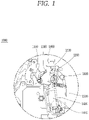
- a trip device 1000 according to the related art is illustrated.
- a shooter hook 1110 of a shooter 1100 is locked by being brought into contact with a crossbar hook 1210 of a crossbar 1200. Accordingly, the shooter 1100 is not rotated, and thus a trip operation is not performed.
- the crossbar 1200 is rotatably provided. When an overcurrent or a fault current flows, the crossbar 1200 is rotated counterclockwise in FIG. 1 . Accordingly, the shooter hook 1110 and the crossbar hook 1210 are separated from each other, the shooter 1100 is rotated, and a trip operation is performed.
- the crossbar 1200 may be rotated under specific conditions. The conditions may be controlled by the crossbar 1200 and an instant bar 1300, respectively.
- a magnitude of a fault current causing the rotation of the crossbar 1200 may be adjusted by the instant bar 1300 and a magnetic part 1400.
- an electromagnet 1410 is magnetized and an armature 1420 is moved.
- a reference fault current may be adjusted by adjusting an elastic force of the elastic body.
- a magnitude of an overcurrent causing the rotation of the crossbar 1200 may be adjusted by a distance between the crossbar 1200 and a bimetal 1500. That is, when an overcurrent occurs, the bimetal 1500 is curved toward the crossbar 1200 to hit the crossbar 1200.
- the magnitude of the overcurrent for performing a trip operation may be adjusted by adjusting the distance between the bimetal 1500 and the crossbar 1200. This may be adjusted by the movement of the crossbar 1200 in a longitudinal direction, in response to rotation of a dial 1600.
- the trip device 1000 includes the crossbar 1200 and the instant bar 1300, respectively. That is, the crossbar 1200 and the instant bar 1300 are spaced apart from each other and rotated centering on separate rotation shafts.
- a bar made of a metal material that serves as the rotation shaft is provided in order to move the crossbar 1200 according to the rotation of the dial 1600.
- the bar is arranged to cross between a plurality of frames through which currents of different phases flow. The bar may be likely to cause interference between the currents of different phases.
- Korean Registration Utility Model No. 20-0156757 discloses an instantaneous trip temporary adjustment device for a molded case circuit breaker. Specifically, the patent document discloses an instantaneous trip temporary adjustment device having a structure capable of simplifying a structure by rotating an instantaneous value setting dial to adjust tensile force of a spring.
- this type of instantaneous trip temporary adjustment device can simplify the structure of a transmission member between the adjustment dial and the spring, but fails to suggest a structure related to the rotation of a crossbar and an instant bar.
- the instantaneous trip temporary adjustment device of the structure also fails to suggest a method for excluding the metal bar disposed in the crossbar.
- Korean Patent Publication No. 10-2017-0076874 discloses a magnetic type trip device of an MCCB. Specifically, the patent document discloses a trip device having a structure capable of preventing an electrical connection between a plurality of conductors by using a base structure having insulating partitions that partition a plurality of insulating spaces accommodating the plurality of conductors.
- this type of trip device does not suggest a method for excluding a metal bar disposed to cross the insulating spaces accommodating the conductors, respectively.
- the prior art document also fails to suggest a method for reducing a space in which a crossbar and an instant bar are rotated.
- the present disclosure describes a crossbar assembly of a structure capable of solving those problems, and a trip device having the same.
- the present disclosure describes a crossbar assembly having a structure capable of miniaturizing a space in which a crossbar and an instant bar are rotated, and a trip device including the same.
- the present disclosure also describes a crossbar assembly having a structure capable of improving arc extinguishing ability generated when a trip device operates, and a trip device including the same.
- the present disclosure further describes a crossbar assembly having a structure capable of facilitating coupling and separation between a crossbar and an instant bar, and a trip device including the same.
- the present disclosure further describes a crossbar assembly having a structure capable of preventing an arbitrary separation when a crossbar and an instant bar are coupled to each other, and a trip device including the same.
- the present disclosure further describes a crossbar assembly having a structure capable of easily adjusting a trip section between a crossbar and an instant bar, and a trip device including the same.
- the present disclosure further describes a crossbar assembly having a structure capable of easily limiting a relative movement distance between a crossbar and an instant bar, and a trip device including the same.
- the present disclosure further describes a crossbar assembly having a structure capable of preventing an occurrence of electrical interference between currents of various phases, and a trip device including the same.
- a crossbar assembly may include a crossbar extending in one direction, and an instant bar extending in the one direction and rotatably coupled to the crossbar.
- the crossbar may include an insertion space portion formed through an inside of the crossbar in the one direction, accommodating the instant bar, and having one side facing the instant bar open, a first body portion extending in the one direction and surrounding a part of the insertion space portion, and a second body portion extending in the one direction and surrounding another part of the insertion space portion.
- Each of the first body portion and the second body portion of the crossbar assembly may have an arcuate cross-section.
- One end portion of the first body portion in an arcuate direction and one end portion of the second body portion in the arcuate direction may be spaced apart from each other at the one side at which the insertion space portion is open.
- a cross-section of the first body portion and a cross-section of the second body portion of the crossbar assembly may be formed in an arcuate shape having the same center.
- the instant bar of the crossbar assembly may include an instant bar body part extending in the one direction, rotatably inserted into the insertion space portion, and having a rounded outer circumferential surface. Also, the instant bar body part may be formed such that a minimum distance from a central axis in the extending direction to the outer circumferential surface is longer than a distance between the one end portion of the first body portion and the one end portion of the second body portion.
- the first body portion of the crossbar of the crossbar assembly may include a movement limiting groove formed therethrough and extending by a predetermined length in the one direction, and the instant bar body part facing the crossbar may include a movement limiting protrusion protruding from one side thereof toward the crossbar and inserted through the movement limiting groove.
- the movement limiting protrusion of the crossbar assembly may include a first portion extending from the outer circumferential surface of the one side of the instant bar body part to form a predetermined angle with the outer circumferential surface of the one side, and a second portion extending from an end of the first portion to form a predetermined angle with the first portion.
- the instant bar of the crossbar assembly may be coupled to the crossbar to be movable in the one direction.
- An extended length of the instant bar of the crossbar assembly may be shorter than an extended length of the crossbar.
- a trip device may include a frame with an inner space, a shooter rotatably coupled to the frame, and a crossbar assembly rotatably coupled to the frame to be brought into contact with or separated from the shooter.
- the crossbar assembly may include a crossbar extending in one direction and including an insertion space portion formed through an inside thereof in the one direction, and an instant bar extending in the one direction and rotatably coupled to the insertion space portion of the crossbar.
- the instant bar of the trip device may include a rotation shaft located on each end portion of the instant bar in the extending direction and rotatably coupled to the frame.
- the crossbar of the trip device may include a shooter contact part protruding toward the shooter, and a contact hook portion extending from an end portion of the shooter contact part toward the shooter while forming a predetermined angle with the shooter contact part.
- the shooter may include a shooter hook portion brought into contact with the contact hook portion and extending toward the shooter contact part.
- the crossbar of the trip device may include a first body portion extending in the one direction and surrounding a part of the insertion space portion, and a second body portion extending from the first body portion in the one direction and surrounding another part of the insertion space portion.
- the second body portion may extend to be shorter than the first body portion, and may be provided in plurality. The plurality of second body portions may be spaced apart from one another by predetermined distances.
- the instant bar of the trip device may include an elastic member coupling part having a coupling groove to which the elastic member is coupled, and protruding from the instant bar, and the elastic member coupling part may be inserted into a movement groove that is a space defined between the plurality of second body portions.
- the instant bar of the trip device may be coupled to the crossbar to be movable relative to the crossbar in the one direction or in another direction opposite to the one direction, and the elastic member coupling part may be moved in the one direction or the another direction between an end portion in the one direction of any one second body portion of adjacent second body portions and an end portion in another direction of the second body portion.
- the crossbar of the trip device may include a movement limiting groove formed through an outer circumferential surface thereof by a predetermined distance in the one direction in which the crossbar extends, and the instant bar may include a movement limiting protrusion protruding toward the movement limiting groove and coupled through the movement limiting groove.
- a crossbar and an instant bar may be arranged to have the same rotation shaft.
- the crossbar and the instant bar may be rotatably coupled to each other.
- the rotation of the crossbar and the rotation of the instant bar may not affect each other.
- a space for rotating the crossbar and a space for rotating the instant bar can be integrated with each other. This can decrease a space to be secured for the rotation of the crossbar and the instant bar and minimize sizes of a trip device and a circuit breaker.
- a decrease in the space for the rotation of the crossbar and the instant bar by such a configuration can cause an increase in a space to be occupied by a generated arc.
- the arc can be cooled and extinguished for a sufficient time before it is discharged from the circuit breaker. This can improve an arc extinguishing ability of the circuit breaker.
- the crossbar and the instant bar can be detachably coupled so as to configure a crossbar assembly.
- a first body portion and a second body portion of the crossbar may be formed of a material that is deformable in a predetermined shape. After the first body portion and the second body portion are deformed when the instant bar is inserted, those body portions can be restored to their original shapes once the instant bar is inserted.
- the first body portion and the second body portion of the crossbar may be deformed and then restored to their original shapes once the instant bar is separated.
- the crossbar may include a movement limiting groove formed therethrough.
- the instant bar may include a movement limiting protrusion protruding therefrom to be inserted through the movement limiting groove.
- the movement limiting protrusion may include a first portion extending at a predetermined angle with an instant bar body part, and a second portion extending at a predetermined angle with the first portion.
- the instant bar in order for the instant bar to be separated from the crossbar, the instant bar must be rotated a plurality of times so that the second portion and the first portion are separated without being caught. This can prevent an arbitrary separation of the instant bar coupled to the crossbar.
- the crossbar may be coupled to the instant bar to be movable in an extending direction. Since the instant bar is rotatably coupled to a frame, it may not be moved regardless of the movement of the crossbar. When the crossbar is moved in the extending direction, a bimetal contact part provided on the crossbar may also be moved in the extending direction.
- One side surface of a bimetal facing the bimetal contact part may be inclined in the extending direction. Accordingly, when the crossbar is moved in the extending direction, a distance between the bimetal contact part and the bimetal can be adjusted.
- a trip section can be easily adjusted merely by moving the crossbar in the extending direction.
- the crossbar may include a movement limiting groove formed therethrough.
- the instant bar may include a movement limiting protrusion protruding therefrom to be inserted through the movement limiting groove.
- the movement limiting groove may extend by a predetermined length in the extending direction of the crossbar.
- the movement limiting groove When the crossbar is moved in the extending direction, the movement limiting groove may also be moved in the extending direction. In this case, since the instant bar is not moved, the movement limiting protrusion may not be moved as well. Therefore, when the crossbar is moved by a predetermined distance, a surface of the crossbar surrounding the movement limiting groove may be brought into contact with the movement limiting protrusion.
- the crossbar may include a movement groove.
- An elastic member coupling part may protrude from the instant bar to be inserted into the movement groove.
- the movement groove may extend by a predetermined length in the extending direction of the crossbar.
- the movement groove When the crossbar is moved in the extending direction, the movement groove may also be moved in the extending direction. In this case, since the instant bar is not moved, the elastic member coupling part may not be moved as well. Accordingly, when the crossbar is moved by a predetermined distance, the second body portion surrounding the movement groove may be brought into contact with the elastic member coupling part.
- the crossbar may be inserted into the instant bar to be movable in the extending direction. That is, the instant bar may function as a guide when the crossbar is moved in the extending direction. Accordingly, a separate member for guiding the movement of the crossbar in the extending direction may not be required. Furthermore, the crossbar body part and the instant bar body part may be formed of an insulating material.
- circuit breaker used in the following description refers to a device that opens and closes an electric circuit.
- the circuit breaker may be a molded case circuit breaker (MCCB).
- overcurrent means a type of current for operating a circuit breaker.
- the overcurrent may be classified as a "small current”.
- the overcurrent may be a current that generates heat by which a bimetal 310 of an operation unit 300 is curved toward a crossbar assembly 400.
- fault current used in the following description means a type of current for operating a circuit breaker.
- the fault current may be classified as a "large current”.
- the fault current may be a current that magnetizes an electromagnet 210 of a driving unit 200 to generate a magnetic field that attracts an armature 220.
- top, bottom, left, bottom, left, right, “front” and “rear” used in the following description will be understood based on a coordinate system illustrated in FIG. 3 .
- a trip device 10 may be provided in a circuit breaker to block a circuit when an overcurrent or a fault current flows.
- the trip device 10 may be disposed in a molded case circuit breaker.
- the trip device 10 may include a frame 100, a driving unit 200, an operation unit 300, and a crossbar assembly 400.
- the frame 100 may define appearance of the trip device 10. Various components for performing a trip operation may be accommodated in the frame 100.
- the frame 100 may be formed of an insulating material. This may prevent an arbitrary electrical connection between inside and outside of the trip device 10.
- the frame 100 may be formed of a material having pressure resistance and thermal resistance. This can prevent damage due to an arc that is generated when a movable contactor and a fixed contactor are separated from each other as the trip device 10 is driven.
- the frame 100 may be formed of a synthetic resin.
- the frame 100 may include a space portion 101, side walls 110, and a heater member 120.
- the frame 100 may include a front wall (not illustrated), a rear wall (not illustrated), an upper wall (not illustrated), and a lower wall (not illustrated) that are continuously formed with the side walls 110 and surround the heater member 120.
- the space portion 101 may be a space in which each component of the trip device 10 is accommodated.
- the driving unit 200 may be accommodated in the space portion 101 and the operation unit 300 may partially be accommodated in the space portion 101.
- the space portion 101 may be provided in plurality.
- the plurality of space portions 101 may be disposed adjacent to each other.
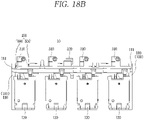
- a total of four space portions 101 may be defined to be continuously arranged adjacent to one another in left and right directions.
- circuit breaker having the trip device 10 is configured to block currents of three phases, which include R-phase, S-phase, and T-phase or U-phase, V-phase, and W-phase, and N-phase.
- the number of the space portion 101 may vary.
- a partition wall may be disposed between the space portions 101.
- the partition wall (not illustrated) may physically partition the adjacent space portions 101.
- the partition wall 120 can prevent an arbitrary contact or electrical connection between components accommodated in the respective space portions 101.
- the side walls 110 may define both sides in a widthwise direction of the frame 100, namely, both right and left outer walls in the illustrated implementation.
- the side walls 110 may be configured to surround the driving unit 200, the operation unit 300, and the crossbar assembly 400.
- Rotation shaft insertion portions 111 may be formed through the side walls 110.
- Rotation shafts 612 of an instant bar 600 may be rotatably inserted into the rotation shaft insertion portions 111.
- the instant bar 600 may be rotated relative to the side walls 110.
- the rotation shaft insertion portion 111 may have a circular cross-section.
- the rotation shaft insertion portion 111 may change to correspond to the cross-sectional shape of the rotation shaft 612.
- the rotation shaft insertion portion 111 may preferably have a cylindrical shape so that the inserted rotation shaft 612 can rotate smoothly.
- the heater member 120 may electrically connect inside and outside of the trip device 10. That is, the heater member 120 may be a portion through which the trip device 10 is electrically connected to the outside.
- the heater member 120 may protrude by predetermined distances from both sides of each space portion 101, namely, from a front upper side and a rear lower side in the illustrated implementation.
- the heater member 120 may extend between the protruded portions.
- the heater member 120 may be continuously formed from the outside of the front side to the outside of the rear side of the frame 100.
- One end portion of the heater member 120 namely, a front end portion in the illustrated implementation may be electrically connected to a fixed contactor disposed in the circuit breaker. When a trip operation is not performed, a current passing through the fixed contactor may be introduced into the heater member 120.
- Another end portion of the heater member 120 may be electrically connected to external power source and load.
- a current flowing into the circuit breaker may flow out to the external power source or load via the heater member 120.
- the heater member 120 may generate heat.
- the heat may cause the bimetal 310 to be curved toward a bimetal contact part 520 so as to strike the crossbar 500.
- the crossbar 500 may be rotated away from the shooter 320, thereby causing a trip operation.
- the heater member 120 When a fault current flows in the heater member 120, the heater member 120 may generate an electromagnetic field. By the electromagnetic field, the electromagnet 210 located adjacent to the heater member 120 may be magnetized.
- the armature 220 may be moved toward the electromagnet 210 and strike the crossbar 500. This may cause the crossbar 500 to be rotated away from the shooter 320, thereby causing a trip operation.
- the driving unit 200 may generate driving force for rotating the crossbar 500.
- the driving unit 200 may be accommodated in the space portion 101 of the frame 100.
- the driving unit 200 may be provided in plurality.
- the plurality of driving units 200 may be accommodated in the plurality of space portions 101, respectively. In the illustrated implementation, four driving units 200 may be provided.
- each space portion 101 may be physically and electrically spaced apart from another space portion 101. Accordingly, each driving unit 200 accommodated in the space portion 101 may also be physically and electrically spaced apart from another driving unit 200.
- the driving unit 200 may be located between a front end portion and a rear end portion of the heater member 120.
- the electromagnetic field generated by the heater member 120 may be utilized to generate a magnetic force for the electromagnet 210 to attract the armature 220.
- the driving unit 200 may include an electromagnet 210, an armature 220, and an elastic member 230.
- the electromagnet 210 may be magnetized by the electromagnetic field generated by the heater member 120.
- the armature 220 spaced apart from the electromagnet 210 may be attracted by a magnetic force generated by the electromagnet 210.
- the electromagnet 210 may be disposed adjacent to the heater member 120. In the illustrated implementation, the electromagnet 210 may be disposed adjacent to the front side of heater member 120. The electromagnet 210 may be disposed at any position at which it can be magnetized by the electromagnetic field generated by the heater member 120.
- the electromagnet 210 may include a plurality of wing portions.
- the plurality of wing portions may respectively be disposed to surround the heater member 120. This can allow the electromagnetic field generated by the heater member 120 to be effectively transmitted to the electromagnet 210. This can also strengthen the magnetic field that the electromagnet 210 applies to the armature 220.
- the electromagnet 210 may be disposed to be spaced apart from the armature 220 by a predetermined distance. By the magnetic force generated by the electromagnet 210, the armature 220 may be moved by the predetermined distance to strike the crossbar 500.
- the armature 220 may be moved toward the electromagnet 210 by the magnetic force generated by the magnetization of the electromagnet 210. Accordingly, the armature 220 can strike the crossbar 500 and the shooter 320 can be rotated, such that a trip operation can be performed.
- the armature 220 may be implemented as any member that can be attracted by magnetic force.
- the armature 220 may be formed of a conductive material such as iron.
- the armature 220 may be disposed to be spaced apart from the heater member 120.
- the armature 220 may also disposed to be spaced apart from the electromagnet 210.
- the armature 220 may be rotatably coupled to the frame 100.
- a lower side of the armature 220 may be coupled to the frame 100 by a hinge member 221. That is, the armature 220 may be rotated centering on the hinge member 221.
- the armature 220 may be connected to the crossbar 500.
- the crossbar 500 may be rotated in a direction to be spaced apart from the shooter 320. Accordingly, the contact state between a shooter hook portion 321 and a contact hook portion 541 can be released and the shooter 320 can be rotated. As a result, the shooter 320 can strike a trip mechanism (not illustrated) to perform a trip operation.
- the armature 220 may be connected to the instant bar 600 through the elastic member 230.
- the elastic member 230 may connect the armature 220 and the instant bar 600.
- the elastic member 230 may apply elastic force for rotating the instant bar 600 when the armature 220 is moved toward the electromagnet 210.
- the elastic member 230 may be arbitrarily configured to be capable of storing restoring force by deformation and applying the stored restoring force to another member.
- the elastic member 230 may be configured as a coil spring.
- Strength of the electromagnetic field generated by the heater member 120 and the magnetic field generated by the electromagnet 210 may depend on a fault current flowing through the heater member 120.
- the elastic member 230 may apply a force to the armature 220 in a direction opposite to the magnetic force. Accordingly, in order for the armature 220 to be moved toward the electromagnet 210, the strength of the magnetic force formed by the electromagnet 210 must be greater than or equal to the elastic force of the elastic member 230.
- the strength of the elastic force or the restoring force of the elastic member 230 can be adjusted so as to adjust the magnitude of the fault current for the trip device 10 to perform a trip operation.
- one end portion of the elastic member 230 may be connected to the armature 220 and another end portion of the elastic member 230 may be connected to an elastic member coupling part 620 of the instant bar 600.
- a plurality of coupling grooves 621, 622, and 623 may be formed in the elastic member coupling part 620. Each coupling groove 621, 622, and 623 may be formed at a different distance from the armature 220.
- the elastic force stored by the elastic member 230 can be adjusted according to the coupling groove 621, 622, 623 to which the elastic member 230 is connected. This can adjust the magnitude of the reference current for performing a trip operation.
- the operation unit 300 may operate to rotate the crossbar 500 when an overcurrent flows through the heater member 120. Accordingly, the shooter 320 may be rotated to cause a trip operation.
- the operation unit 300 may partially be accommodated in the space portion 101 of the frame 100.
- the shooter 320 of the operation unit 300 may be rotatably coupled to the frame 100. In the illustrated implementation, it will be understood that the coupled state between the shooter 320 and the frame 100 is not illustrated.
- the operation unit 300 may be provided in plurality.
- the bimetal 310 of the operation unit 300 may be provided in plurality.
- the plurality of bimetals 310 may be partially accommodated in the plurality of space portions 101, respectively.
- four bimetals 310 may be provided.
- the operation unit 300 may include a bimetal 310 and a shooter 320.
- the bimetal 310 may be curved by heat generated by the heater member 120 as an overcurrent flows.
- the bimetal 310 may be curved toward the bimetal contact part 520 of the crossbar 500.
- the bimetal 310 When the bimetal 310 is curved over a predetermined distance, that is, a distance between the bimetal 310 and the bimetal contact part 520, the bimetal 310 may hit the bimetal contact part 520. Responsive to this, the crossbar 500 to which the bimetal contact part 520 is connected can be rotated, the contact state with the shooter 320 can be released, and thus the shooter 320 can be rotated. This may result in causing the trip operation.
- the bimetal 310 may be formed of two or more materials having different thermal expansion coefficients. At this time, the bimetal 310 should be curved toward the bimetal contact part 520. Therefore, a thermal expansion coefficient of one side of the bimetal 310 facing the bimetal contact part 520 may preferably be smaller than a thermal expansion coefficient of another side disposed in the direction away from the bimetal contact part 520.
- the bimetal 310 may extend from the heater member 120 up to the bimetal contact part 520.
- the bimetal 310 may extend from the front lower side of the space portion 101 up to a height adjacent to the bimetal contact part 520 in the vertical direction.
- One side surface of the bimetal 310 facing the bimetal contact part 520 may be inclined.
- the one side surface of the bimetal 310 may be inclined in the extending direction of the crossbar assembly 400, namely, in the left and right directions in the illustrated implementation.
- the shortest distance between the end portion of the bimetal contact part 520 and the bimetal 310 can be adjusted. This can allow the adjustment of a distance by which the bimetal 310 needs to be moved to perform the trip operation, that is, a trip distance.
- the shooter 320 may be rotated by the rotation of the crossbar 500 to hit a trip mechanism provided in the circuit breaker. This can cause the trip operation.
- the shooter 320 may be rotatably coupled to the circuit breaker.
- the coupled state between the shooter 320 and the circuit breaker is not illustrated as described above.
- the shooter 320 may be connected to the trip mechanism (not illustrated). The shooter 320 may be rotated to hit the trip mechanism (not illustrated), thereby causing the trip operation.
- the armature 320 may be in contact with the crossbar 500. Specifically, the shooter hook portion 321 of the shooter 320 may be in contact with the contact hook portion 541 of the crossbar 500. Accordingly, when no fault current or overcurrent flows, arbitrary rotation of the shooter 320 can be prevented.
- a single shooter 320 may be provided.
- the shooter 320 may be disposed between the bimetal contact portions 520 adjacent to each other.
- the shooter 320 may be disposed such that two bimetal contact portions 520 are located at each of left and right sides thereof.
- the position of the shooter 320 may change depending on the position of the shooter contact part 540 of the crossbar 500.
- An elastic member may be provided on one side of the shooter 320 in the direction away from the crossbar 500, namely, on the front side in the illustrated implementation.
- the elastic member may apply elastic force such that the shooter 320 can be rotated away from the crossbar 500, namely, in a clockwise direction in the illustrated implementation.
- the shooter 320 can be instantaneously rotated clockwise and hit the trip mechanism (not illustrated).
- the shooter 320 may include a shooter hook portion 321 and a shooter rotation shaft 322.
- the shooter hook portion 321 may be a portion where the shooter 320 is in contact with the crossbar 500. In addition, the shooter hook portion 321 can prevent arbitrary rotation of the shooter 320.
- the shooter hook portion 321 may be located on one end portion of the shooter 320 facing the crossbar 500.
- the shooter hook portion 321 may protrude from the one end portion of the shooter 320 in a direction away from the crossbar 500, namely, upward in the illustrated implementation.
- the shooter hook portion 321 may be brought into contact with the contact hook portion 541. In addition, the shooter hook portion 321 may be hooked onto the contact hook portion 541.
- the shooter hook portion 321 may be coupled to the contact hook portion 541 by applying a force to the shooter contact part 540 in a direction from bottom to top.
- the contact hook portion 541 may be coupled to the shooter hook portion 321 by applying a force to the shooter 320 in a direction from top to bottom.
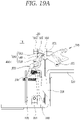
- the crossbar 500 When a fault current or an overcurrent flows in the heater member 120, the crossbar 500 may be rotated in a direction in which the contact hook portion 541 and the shooter hook portion 321 are spaced apart from each other, that is, in the counterclockwise direction in the implementation illustrated in FIGS. 19A and 19B . Accordingly, the contact state between the contact hook portion 541 and the shooter hook portion 321 can be released and the shooter 320 can be free. The shooter 320 can thusly be rotated clockwise in the implementation illustrated in FIGS. 19A and 19B , to hit the trip mechanism (not illustrated).
- the shooter rotation shaft 322 may be a portion by which the shooter 320 is rotatably coupled to the trip device 10. The shooter 320 released from the crossbar 500 through the process can be rotated centering on the shooter rotation shaft 322.
- the trip device 10 may include the crossbar assembly 400.
- the crossbar assembly 400 When an overcurrent or a fault current flows in the heater member 120, the crossbar assembly 400 may be rotated according to the operation of the driving unit 200 or the operation unit 300. The shooter 320 may be released from the crossbar 500, in response to the rotation of the crossbar assembly 400, to strike the trip mechanism (not illustrated). This can result in performing a trip operation.
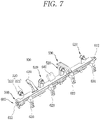
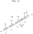
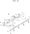
- the crossbar assembly 400 may include the crossbar 500 and the instant bar 600.
- the crossbar 500 may be rotated centering on the same central shaft as the instant bar 600.
- the space required for rotation can be decreased.
- the crossbar 500 and the instant bar 600 may be coupled to be relatively movable in the longitudinal direction, namely, in the left and right directions in the illustrated implementation. That is, when the crossbar 500 is moved to adjust the distance between the bimetal 310 and the bimetal contact part 520, a bar made of a metal material to serve as a movement shaft may be unnecessary.
- conductor members crossing each space portion 101 through which currents of different phases flow may not be needed, thereby minimizing electrical interference between the currents of the different phases.
- crossbar assembly 400 according to the implementation will be described in detail, with reference to FIGS. 5 to 16 .
- the crossbar assembly 400 may be configured by the combination of the crossbar 500 and the instant bar 600. Accordingly, it will be understood that the crossbar assembly 400 includes the crossbar 500 and the instant bar 600.
- crossbar 500 according to the implementation will be described in detail, with reference to FIGS. 5 to 11 .
- the crossbar 500 may configure the crossbar assembly 400 together with the instant bar 600.
- the crossbar 500 may lock the shooter 320. Accordingly, the rotation of the shooter 320 can be prevented, thereby maintaining the electrical connection between the inside and outside of the circuit breaker.
- the crossbar 500 When an overcurrent or a fault current flows in the heater member 120, the crossbar 500 may be rotated to release the shooter 320. Accordingly, the shooter 320 can be rotated to strike the trip mechanism (not illustrated), and as a result, the trip operation can be performed, so that the electrical connection between the inside and the outside of the circuit breaker can be cut off.
- the crossbar 500 may be rotatably coupled to the instant bar 600.
- the crossbar 500 may be rotated relative to the instant bar 600. Accordingly, regardless of the rotation of the instant bar 600, the crossbar 500 can be rotated to perform a trip operation.
- the crossbar 500 may be coupled to the instant bar 600 so as to be movable in its extending direction, namely, in the left and right directions in the illustrated implementation.
- the crossbar 500 may be moved in the longitudinal direction to be relative to the instant bar 600. Accordingly, regardless of the movement of the instant bar 600, the crossbar 500 can be moved so as to adjust a trip distance, which is the distance between the bimetal 310 and the bimetal contact part 520.
- the crossbar 500 may extend in one direction, namely, in the left and right directions in the illustrated implementation.
- An extended length of the crossbar 500 may preferably be shorter than a distance between the side walls 110 of the frame 100. Accordingly, the crossbar 500 can be moved between the side walls 110 in the coupled state with the instant bar 600.
- the crossbar 500 may be formed of an insulating material. This can prevent the occurrence of electrical interference between the components accommodated in each space portion 101 when the crossbar 500 extends between the side walls 110 and passes through each space portion 101.
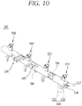
- the crossbar 500 may include a crossbar body part 510, a bimetal contact part 520, a knob coupling part 530, and a shooter contact part 540.
- the crossbar body part 510 may define the body of the crossbar 500.
- the crossbar body part 510 may extend in one direction, namely, in the left and right directions in the illustrated implementation.
- An extended length of the crossbar body part 510 may preferably be shorter than the distance between the side walls 110 of the frame 100.
- the extended length of the crossbar body part 510 may preferably be shorter than an extended distance between an instant bar body part 610 of the instant bar 600.
- a hollow portion may be formed inside the crossbar body part 510.
- the hollow portion may be defined as an insertion space portion 513.
- the instant bar 600 may be rotatably coupled to the insertion space portion 513.
- the crossbar body part 510 may be formed in a cylindrical shape that has a circular cross-section and extends in one direction, namely, in the left and right directions in the illustrated implementation. Accordingly, an outer circumferential surface of the crossbar body part 510 in the longitudinal direction may define a side surface of a cylinder.
- the shape of the crossbar body part 510 may change to any shape that can be coupled to be rotatable relative to the instant bar 600.
- the crossbar body part 510 may preferably be formed of a material that has a predetermined elasticity to be restored after being deformed. As will be described later, the instant bar 600 may be coupled after a first body portion 511 and a second body portion 512 are deformed in shape, and then the crossbar body part 510 may be restored to its original shape by the elasticity.
- the crossbar body part 510 may include a first body portion 511, a second body portion 512, an insertion space portion 513, a movement limiting groove 514, a fixing jaw 515, a rotation shaft coupling portion 516, a rotation shaft support portion 517, and a movement groove 518.
- the first body portion 511 may configure a part of the crossbar body part 510. Specifically, the first body portion 511 may define one side of the crossbar body part 510 in a direction away from the instant bar 600, namely, upper and front sides in the illustrated implementation.
- the crossbar body part 510 may be formed in the cylindrical shape. Accordingly, the first body portion 511 may also be rounded to be convex in a direction away from the instant bar 600. In other words, the first body portion 511 may be formed in an arcuate shape whose cross-section is convex toward the outside.
- the first body portion 511 may extend in one direction, namely, in the left and right directions in the illustrated implementation.
- An extended length of the first body portion 511 may preferably be shorter than the distance between the side walls 110 of the frame 100.
- the first body portion 511 may partially surround the insertion space portion 513. Specifically, the first body portion 511 may surround the front side and the upper side of the insertion space portion 513 in the illustrated implementation.
- the movement limiting groove 514 may be formed through the first body portion 511.
- a bimetal contact part 520, a knob coupling part 530, and a shooter contact part 540 may protrude from the first body portion 511.
- a lower end portion of the first body portion 511 may be continuously formed with the second body portion 512.
- the second body portion 512 may configure a part of the crossbar body part 510. Specifically, the second body portion 512 may configure another side of the crossbar body part 510 facing the instant bar 600, namely, the lower side in the illustrated implementation.
- the second body portion 512 may be continuously formed with the first body portion 511. Specifically, a front end portion of the second body portion 512 may be continuously formed with the lower end portion of the first body portion 511.
- the crossbar body part 510 may be formed in the cylindrical shape. Accordingly, the second body portion 512 may also be rounded to be convex in a direction away from the instant bar 600. In other words, the second body portion 512 may be formed in an arcuate shape whose cross-section is convex toward the outside.
- the second body portion 512 may extend in one direction, namely, in the left and right directions in the illustrated implementation.
- the second body portion 512 may preferably be shorter than the extended length of the first body portion 511.
- the second body portion 512 may partially surround the insertion space portion 513. Specifically, the second body portion 512 may partially surround the lower side of the insertion space portion 513.
- the second body portion 512 may be provided in plurality.
- the plurality of second body portions 512 may be spaced apart from one another by predetermined distances in the direction in which the second body portion 512 extends, namely, in the left and right directions in the illustrated implementation.
- four second body portions 512 may be provided.
- the movement groove 518 may be formed between the second body portions 512 adjacent to each other.
- the second body portion 512 may be disposed such that the position of each movement groove 518 corresponds to the position of the elastic member coupling part 620 of the instant bar 600.
- the fixing jaw 515 may protrude from an inner surface of the second body portion 512, that is, one side surface of the second body portion 512 facing the insertion space portion 513.
- the fixing jaw 515 can prevent the instant bar body part 610 inserted into the insertion space portion 513 from being arbitrarily separated from the insertion space portion 513.
- the insertion space portion 513 may be a space into which the instant bar body part 610 is inserted.
- the insertion space portion 513 may be defined as a space surrounded by the first body portion 511 and the second body portion 512.
- one side of the insertion space portion 513 facing the shooter 320 may be surrounded by the first body portion 511.
- another side of the insertion space portion 513 facing the space portion 101, that is, the lower side in the illustrated implementation may be surrounded by the second body portion 512.
- One side of the insertion space portion 513 facing the instant bar 600 may be open. Accordingly, the instant bar 600 can be inserted into the insertion space portion 513 through the open rear side of the insertion space portion 513.
- the insertion space portion 513 may extend in one direction, namely, in the left and right directions in the illustrated implementation. This may result from that the first body portion 511 and the second body portion 512 surrounding the insertion space portion 513 extend in the above direction.
- the insertion space portion 513 may be defined as a cylindrical hollow portion having a circular cross-section. This may result from that each cross-section of the first body portion 511 and the second body portion 512 is formed in an arcuate shape.
- the shape of the insertion space portion 513 may vary. However, in order for the crossbar 500 and the instant bar 600 to be smoothly rotated relative to each other, the insertion space portion 513 may preferably be a cylindrical hollow portion.
- the insertion space portion 513 may communicate with the movement limiting groove 514 located on the front side.
- a movement limiting protrusion 630 that extends from the instant bar body part 610 inserted into the insertion space portion 513 may be inserted through the movement limiting groove 514.
- the insertion space portion 513 may communicate with rotation shaft coupling portions 516 that are formed in both end portions in the extending direction, namely, left and right end portions in the illustrated implementation, respectively.
- the rotation shafts 612 that protrude from both end portions of the instant bar body part 610 inserted into the insertion space portion 513 may be inserted through the rotation shaft coupling portions 516, respectively.
- the insertion space portion 513 may communicate with the movement limiting groove 518 located on the lower side.
- the elastic member coupling part 620 that extends from the instant bar body part 610 inserted into the insertion space portion 513 may be inserted through the movement groove 518.
- the crossbar 500 and the instant bar 600 can be rotated relative to each other.
- the inserted instant bar 600 and the crossbar 500 may be moved relative to each other in the extending one direction, namely, in the left and right directions in the illustrated implementation.
- the movement limiting groove 514 may be configured to limit the relative rotation and movement of the crossbar 500 and the instant bar 600.
- the movement limiting protrusion 630 of the instant bar 600 may be inserted through the movement limiting groove 514.
- the movement limiting groove 514 may be formed through the first body portion 511.
- the movement limiting groove 514 may be located to be biased in one direction in which it extends, namely, biased to the left side.
- the movement limiting groove 514 may be located between a bimetal contact part 520 located at the leftmost side and another bimetal contact part 520 adjacent thereto.
- the position of the movement limiting groove 514 may vary depending on the position of the movement limiting protrusion 630 of the instant bar 600 coupled to the crossbar 500.
- the movement limiting groove 514 may extend by a predetermined length in each of the longitudinal direction and a circumferential direction of the first body portion 511. That is, the movement limiting groove 514 may have a rectangular cross-section with a long side in the extending direction of the first body portion 511 and a short side in the circumferential direction.
- the movement limiting groove 514 may be formed in any shape into which the movement limiting protrusion 630 can be inserted and in which the movement limiting protrusion 630 can be brought into contact with a surface surrounding the movement limiting groove 514 when the crossbar 500 or the instant bar 600 is rotated or moved.
- Two surfaces surrounding the movement limiting groove 514 that is, two surfaces that extend in the circumferential direction of the first body portion 511 and face each other may be defined as "movement limiting surfaces”.
- the movement limiting surfaces may limit a relative movement distance of the crossbar 500 and the instant bar 600 in the extending direction thereof.
- the crossbar 500 may be moved to the left or right relative to the instant bar 600.
- the movement limiting protrusion 630 may be brought into contact with one of the movement limiting surfaces that is located in an opposite direction.
- the movement limiting protrusion 630 may be brought into contact with a movement limiting surface located at the left side.
- the movement limiting protrusion 630 may be brought into contact with a movement limiting surface located at the right side.
- the distance by which the crossbar 500 is moved relative to the instant bar 600 in the extending direction can be limited.
- the distance may preferably be determined depending on a length of an inclined surface of the bimetal 310.
- the fixing jaw 515 may prevent the instant bar body part 610 inserted into the insertion space portion 513 from being arbitrarily separated from the insertion space portion 513. In one implementation, the fixing jaw 515 may press the inserted instant bar body part 610.
- the fixing jaw 515 may protrude by a predetermined length from an inner surface of the second body portion 512, that is, one side surface of the second body portion 512 facing the insertion space portion 513. Accordingly, the instant bar body part 610 can be fitted into the insertion space portion 513.
- the fixing jaw 515 may be provided in plurality. In the illustrated implementation, the fixing jaws 515 may be disposed on the two second body portions 512 that are located to be biased to the right. Alternatively, the fixing jaw 515 may be disposed for each second body portion 512.
- the rotation shaft coupling portions 516 may be spaces into which the rotation shafts 612 of the instant bar 600 are rotatably coupled.
- the rotation shaft coupling portions 516 may be located in the extending direction of the first body portion 511, namely, on the left and right end portions in the illustrated implementation.
- the rotation shaft coupling portions 516 may be surrounded by the rotation shaft support portions 517.
- the rotating shaft coupling portions 516 may communicate with the outside.
- the rotation shafts 612 inserted into the rotation shaft coupling portions 516 can be rotatably inserted into the rotation shaft insertion portions 111 of the side walls 110.
- the rotation shaft coupling portions 516 may communicate with the insertion space portion 513.
- the rotating shafts 612 may protrude from the respective end portions in the extending direction of the instant bar body part 610 inserted into the insertion space portion 513 to be inserted into the rotating shaft coupling portions 516.
- the rotation shaft support portions 517 may partially surround the rotation shaft coupling portions 516. Specifically, the rotation shaft support portions 517 may surround upper and lower sides of the rotation shaft coupling portions 516.
- the rotation shaft support portions 517 may rotatably support the rotation shafts 612.
- the rotation shaft support portions 517 may include first support portions located on both end portions in the extending direction of the first body portion 511, and a second support portion located on one end portion in the extending direction of the second body portion 512, namely, on the left end portion in the illustrated implementation.
- the first support portions and the second support portion may support upper and lower sides of the rotation shafts 612, respectively.
- the movement groove 518 may be a space into which the elastic member coupling part 620 of the instant bar 600 is inserted.
- the movement groove 518 may be formed as the plurality of second body portions 512 are spaced apart from each other. That is, the movement groove 518 may be a space defined between the second body portions 512 adjacent to each other.
- the movement groove 518 may be provided in plurality. In the illustrated implementation, the movement grooves 518 may be provided totally by four, namely, three defined between the adjacent second body portions 512, and one defined between the rightmost second body portion 512 and the side wall 110. The number of the movement groove 518 may change depending on the number of the elastic member coupling part 620.
- the elastic member 230 connecting the instant bar 600 and the armature 220 may be coupled to the elastic member coupling part 620 through the movement groove 518.
- the movement groove 518 may provide a space in which the crossbar 500 can be moved relative to the instant bar 600 in the extending direction. To this end, the movement groove 518 may extend in one direction, namely, in the left and right directions in the illustrated implementation.
- the crossbar 500 may be moved to the left or right relative to the instant bar 600.
- the elastic member coupling part 620 may be brought into contact with the right end of the second body portion 512 located at the left side.
- the elastic member coupling part 620 may be brought into contact with the left end of the second body portion 512 located at the right side.
- the distance by which the crossbar 500 is moved relative to the instant bar 600 in the extending direction can be limited.
- the distance may preferably be determined depending on a length of an inclined surface of the bimetal 310.
- an extended length of each of the plurality of movement grooves 518 in the longitudinal direction, that is, in the left and right directions may preferably be the same.
- the bimetal contact part 520 may be a portion with which the bimetal 310 comes in contact when it is curved by heat of the heater member 120 through which an overcurrent flows.
- the bimetal 310 may be formed of two or more materials having different thermal expansion coefficients. At this time, a thermal expansion coefficient of a material located on one side of the bimetal 310 facing the bimetal contact part 520 may be smaller than a thermal expansion coefficient of a material located on another side of the bimetal 310 in a direction away from the bimetal contact part 520.
- the bimetal 310 may be curved toward the bimetal contact part 520 to hit the bimetal contact part 520.
- the crossbar 500 can thusly be rotated to make the shooter 320 free, thereby causing a trip operation.
- the bimetal contact part 520 may be coupled to the first body portion 511. Specifically, the bimetal contact part 520 may protrude from an upper surface of the first body portion 511.
- the bimetal contact part 520 may be provided in plurality.
- the plurality of bimetal contact portions 520 may be spaced apart from one another by predetermined distances.
- four bimetal contact portions 520 may be disposed along the extending direction of the first body portion 511. The number of the bimetal contact part 520 may change depending on the number of the bimetal 310.
- the bimetal contact portions 520 may be spaced apart from one another by predetermined distances. A distance between the adjacent bimetal contact portions 520 may preferably be determined depending on a distance between the adjacent bimetals 310.
- the bimetal contact part 520 may include a contact member 521 and a support member 522.
- the contact member 521 may be a portion with which the curved bimetal 310 comes in contact.
- the contact member 521 may protrude by a predetermined length toward the bimetal 310, namely, toward the front side in the illustrated implementation.
- the contact member 521 may protrude by a predetermined length in one direction toward the bimetal 310, namely, in front and rear directions in the illustrated implementation.
- the contact member 521 may be provided in plurality.
- the plurality of contact members 521 may be spaced apart from one another by predetermined distances.
- the crossbar 500 may be moved along the extending direction.
- the movement distance of the crossbar 500 may preferably be determined so that the contact member 521 is located on an inclined surface of the bimetal 310.
- the contact member 521 may also be located on the one side of the inclined surface of the bimetal 310.
- the contact member 521 may also be located on the another side of the inclined surface of the bimetal 310.
- one side of the bimetal 310 facing the contact member 521 namely, the rear side surface in the illustrated implementation, may be inclined in the direction in which the first body portion 511 extends.
- the crossbar 500 when the crossbar 500 is moved in the extending direction, the shortest distance between the contact member 521 and the bimetal 310 can be adjusted. This can adjust a trip section for performing a trip operation.
- the shortest distance is a distance between one end of the contact member 521 facing the bimetal 310 and one side of the bimetal 310 facing the contact member 521.
- the contact member 521 may be coupled through the support member 522.
- the contact member 521 and the support member 522 may be integrally formed with each other.
- the support member 522 may extend from the first body portion 511 to support the contact member 521.
- the contact member 521 may be coupled through the support member 522.
- the support member 522 may be provided in plurality.
- the plurality of support members 522 may be spaced apart from one another by predetermined distances. In the illustrated implementation, four support members 522 may be provided.
- a criterion for the predetermined distance by which the support members 522 are spaced apart from each other may be the same as a criterion for the distance by which the contact members 521 are spaced apart from each other.
- the contact member 521 may be coupled through the support member 522.
- the support member 522 may adjust a length by which the contact member 521 is exposed in a direction toward the bimetal 310. Accordingly, the distance between the bimetal 310 and the contact member 521 can be adjusted, resulting in adjusting the trip section.
- a lower side of the support member 522 may extend from the first body portion 511.
- the support member 522 and the first body portion 511 may be integrally formed with each other.
- the support member 522 may include a contact member insertion hole 522a.
- a contact member 521 may be inserted through the contact member insertion hole 522a.
- the contact member insertion hole 522a may include a separate fastening member (not illustrated).
- the fastening member (not illustrated) may prevent an arbitrary separation of the inserted contact member 521 or limit an arbitrary change in the distance from the bimetal 310.
- the knob coupling part 530 may be a portion to which a knob or dial (not illustrated) is rotatably coupled. A rotary motion of the knob (not illustrated) may be converted into a linear motion of the crossbar 500 by the knob coupling part 530.
- the knob coupling part 530 may be located on the first body portion 511.
- the knob coupling part 530 may extend from an upper side of the first body portion 511 in a direction away from the instant bar 600.
- the knob coupling part 530 may be located between two bimetal contact portions 520 located at the right side.
- the knob coupling part 530 may be disposed at any position to which the knob (not illustrated) can be rotatably coupled.
- the knob coupling part 530 may include a first extension portion 531, a second extension portion 532, and a knob insertion space portion 533.
- the first extension portion 531 and the second extension portion 532 may extend in a direction away from the instant bar 600.
- the first extension portion 531 and the second extension portion 532 may support the knob (not illustrated) inserted into the knob insertion space portion 533.
- the first extension portion 531 and the second extension portion 532 may be spaced apart from each other by a predetermined distance.
- a space defined as the first extension portion 531 and the second extension portion 532 are spaced apart from each other may be the knob insertion space portion 533.
- the knob (not illustrated) may be rotatably inserted into the knob insertion space portion 533.
- the shooter contact part 540 may be a portion where the crossbar 500 is in contact with the shooter 320. In a state in which a normal current flows through the heater member 120, the shooter contact part 540 may lock the shooter 320 to prevent arbitrary rotation of the shooter 320.
- the shooter contact part 540 may be disposed on the first body portion 511. Specifically, the shooter contact part 540 may be located on an upper portion, which covers the insertion space portion 513 from the upper side, of the first body portion 511.
- the shooter contact part 540 may be located at a middle portion in the extending direction of the first body portion 511. That is, the shooter contact part 540 may be located between the two bimetal contact parts 520, which are located at the middle portion in the extending direction of the first body portion 511, among the plurality of bimetal contact parts 520.
- the position of the shooter contact part 540 may change depending on the position of the shooter 320.
- the shooter contact part 540 may extend from the first body portion 511 toward the shooter 320 by a predetermined length. That is, the shooter contact part 540 may extend from the first body portion 511 to be away from the instant bar 600.
- the shooter contact part 540 may extend at a predetermined angle with a plane, which comes in contact with an outer circumferential surface of the first body portion 511 passing through the contact portion between the shooter contact part 540 and the first body portion 511. That is, the shooter contact part 540 may extend obliquely with respect to the plane.
- the shooter contact part 540 may extend at a predetermined angle with the front end or rear end of the heater member 120.
- the shooter contact part 540 may extend so that an end portion thereof facing the shooter 320 comes in contact with the shooter 320.
- a contact hook portion 541 may be disposed on the end portion of the shooter contact part 540.
- the contact hook portion 541 may come in contact with the shooter hook portion 321.
- the contact hook portion 541 may be coupled to the shooter hook portion 321 to suppress the shooter 320 from being arbitrarily rotated unless the crossbar 500 is rotated.
- the contact hook portion 541 may extend from the end portion of the shooter contact part 540 toward the shooter 320 by a predetermined length.
- a predetermined space may be defined between the contact hook portion 541 and the shooter contact part 540.
- the shooter hook portion 321 may be inserted into the space.
- a predetermined space may be defined between the shooter hook portion 321 and the shooter 320.
- the contact hook portion 541 may be inserted into the space.
- the contact hook portion 541 and the shooter hook portion 321 are coupled to each other in a staggered manner.
- the contact hook portion 541 may be located between the shooter hook portion 321 and the shooter 320.
- the shooter 320 may be connected to an elastic member (not illustrated) that applies a pulling force from bottom to top, that is, in the clockwise direction in the illustrated implementation. At this time, the contact hook portion 541 may press the shooter 320 from top to bottom, thereby limiting the rotation of the shooter 320.
- the contact hook portion 541 and the shooter hook portion 321 may be hooked onto each other. Accordingly, unless the crossbar 500 is rotated counterclockwise, the shooter 320 cannot be rotated arbitrarily.
- the instant bar 600 may configure the crossbar assembly 400 together with the crossbar 500. As described above, when a normal current flows through the heater member 120, the shooter 320 may not be rotated since the crossbar 500 locks the shooter 320.
- the crossbar 500 When an overcurrent or a fault current flows in the heater member 120, the crossbar 500 may be rotated to release the shooter 320. Accordingly, the shooter 320 can be rotated to strike the trip mechanism (not illustrated), and as a result, the trip operation can be performed, so that the electrical connection between the inside and the outside of the circuit breaker can be cut off.
- a reference current for rotating the crossbar 500 to release the shooter 320 may be a problem. That is, it may be necessary to set a magnitude of a current for determining whether an overcurrent or a fault current flows.
- a magnitude of a current as a reference may be adjusted by adjusting the distance between the bimetal 310 and the bimetal contact part 520 of the crossbar 500.
- the magnitude of the reference current may be adjusted by adjusting the elastic force of the elastic member 230 connecting the armature 220 and the instant bar 600. That is, the instant bar 600 may be rotated to adjust the distance from the armature 220, thereby adjusting strength of the elastic force stored in the elastic member 230.
- the instant bar 600 can be rotated to adjust the magnitude of the overcurrent for performing a trip operation.
- the instant bar 600 may be rotatably coupled to the crossbar 500.
- the instant bar 600 may be rotated relative to the crossbar 500. Accordingly, even if the crossbar 500 is not rotated, the instant bar 600 can be rotated to adjust the magnitude of the overcurrent for performing the trip operation.
- the crossbar 500 When the instant bar 600 and the crossbar 500 are coupled to each other, the crossbar 500 may be moved relative to the instant bar 600 in the extending direction. Accordingly, even though the instant bar 600 is not moved, the crossbar 500 can be moved so as to adjust a trip distance, which is the distance between the bimetal 310 and the bimetal contact part 520.
- the instant bar 600 may extend in one direction, namely, in the left and right directions in the illustrated implementation. That is, the instant bar 600 may extend in the same direction as the crossbar 500.
- An extended length of the instant bar 600 may be longer than the extended length of the crossbar 500.
- the extended length of the instant bar 600 may be the same as the distance between the side walls 110 of the frame 100. Accordingly, the rotation shafts 612 can be stably and rotatably inserted into the rotation shaft insertion portions 111 of the side walls 110.
- the instant bar 600 may be formed of an insulating material. This can prevent the occurrence of electrical interference between the components accommodated in each space portion 101 when the instant bar 600 extends between the side walls 110 and passes through each space portion 101.
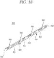
- the instant bar 600 may include an instant bar body part 610, an elastic member coupling part 620, and a movement limiting protrusion 630.
- the instant bar body part 610 may define the body of the instant bar 600.
- the instant bar body part 610 may extend in one direction, namely, in the left and right directions in the illustrated implementation.
- An extended length of the instant bar body part 610 may preferably be shorter than the distance between the side walls 110 of the frame 100.
- the instant bar body part 610 may be formed in a cylindrical shape that has a circular cross-section and extends in one direction, namely, in the left and right directions in the illustrated implementation. Accordingly, an outer circumferential surface of the instant bar body part 610 in the longitudinal direction may define a side surface of a cylinder.
- the shape of the instant bar body part 610 may preferably be determined depending on the shape of the insertion space portion 513.
- a plurality of weight-reducing grooves 611 may be formed inside the instant bar body part 610. Also, the rotation shaft 612 may protrude from each end portion of the instant bar body part 610 in the extending direction.
- the weight-reducing grooves 611 may reduce the mass of the instant bar body part 610.
- partition walls formed between the weight-reducing grooves 611 can reinforce rigidity of the instant bar body part 610 in the extending direction.
- the weight-reducing grooves 611 may extend in one direction, namely, in the left and right directions in the illustrated implementation. That is, the weight-reducing grooves 611 may extend in the same direction as the instant bar body part 610.
- the weight-reducing grooves 611 may be provided in plurality.
- the plurality of weight-reducing grooves 611 may be spaced apart from one another by predetermined distances in the direction in which the instant bar body part 610 extends.
- the plurality of weight-reducing grooves 611 may be provided in the circumferential direction of the instant bar body part 610 to be spaced apart from one another by predetermined distances.
- the shape, number, and position of the weight-reducing groove 611 may change.
- the rotation shafts 612 may allow the instant bar body part 610 to be rotatably coupled to the frame 100.
- the rotation shafts 612 may protrude by predetermined lengths from the respective end portions of the instant bar body part 610 in the extending direction.
- the rotation shafts 612 may be rotatably inserted into the rotation shaft insertion portions 111 of the side walls 110.
- the rotation shafts 612 and the rotation shaft insertion portions 111 may be disposed to have the same central axis.
- the maximum distance from the center to an outer circumference of the rotation shaft 612 may be smaller than a diameter of the instant bar body part 610.
- the rotation shaft 612 When the instant bar 600 is coupled to the crossbar 500, the rotation shaft 612 may be accommodated in the rotation shaft coupling portion 516 of the crossbar 500. An upper or lower side of the rotation shaft 612 may be covered by the rotation shaft support portion 517. Accordingly, the rotation shaft 612 can be supported by the rotation shaft support portion 517.
- the elastic member coupling part 620 may be a portion to which the elastic member 230 connecting the armature 220 and the instant bar 600 is coupled.
- the elastic member coupling part 620 may extend away from the crossbar 500. In other words, the elastic member coupling part 620 may extend away from the shooter 320. In the illustrated implementation, the elastic member coupling part 620 may extend toward a lower side of the rear.
- the elastic member coupling part 620 may be provided in plurality.
- the plurality of elastic member coupling parts 620 may be spaced apart from one another by predetermined distances. In the illustrated implementation, four elastic member coupling parts 620 may be provided. The position and number of the elastic member coupling part 620 may change depending on the number of the space portion 101 and the movement groove 518.
- the elastic member coupling part 620 When the instant bar 600 is coupled to the crossbar 500, the elastic member coupling part 620 may be accommodated in the movement groove 518 that communicates with the insertion space portion 513. When the crossbar 500 is moved relative to the instant bar 600 in its extending direction, the elastic member coupling part 620 may be brought into contact with any one of the second body portions 512 defining the movement groove 518.
- a distance by which the crossbar 500 is moved in the extending direction can be limited.
- the elastic member coupling part 620 may include a first coupling groove 621, a second coupling groove 622, and a third coupling groove 623.
- One end portion of the elastic member 230 may be coupled to any one of the first coupling groove 621, the second coupling groove 622, and the third coupling groove 623.
- the first to third coupling grooves 621, 622, and 623 may be recessed by predetermined distances into one side surface of the elastic member coupling part 620.
- the elastic member 230 coupled to any one of the first to third coupling grooves 621, 622, and 623 cannot be arbitrarily moved to another coupling groove 621, 622, 623.
- the first coupling groove 621 may be located at the uppermost side. That is, the first coupling groove 621 may be located closest to the instant bar body part 610.
- the second coupling groove 622 may be located at a middle portion. That is, the second coupling groove 622 may be located between the first coupling groove 621 and the third coupling groove 623.
- the third coupling groove 623 may be located at the lowermost side. That is, the third coupling groove 623 may be located farthest from the instant bar body part 610.
- the elastic force stored in the elastic member 230 can be adjusted by rotating the instant bar 600.
- the elastic member 230 can be coupled to any one of the first to third coupling grooves 621, 622, and 623, so as to more precisely adjust the elastic force stored in the elastic member 230.
- the movement limiting protrusion 630 may limit the movement distance of the crossbar 500 relative to the instant bar 600. As described above, the process can also be achieved by the contact between the elastic member coupling part 620 and the movement groove 518.
- the movement limiting protrusion 630 may protrude by a predetermined length from the instant bar body part 610 toward the crossbar 500. When the instant bar 600 is coupled to the crossbar 500, the movement limiting protrusion 630 may be inserted through the movement limiting groove 514.
- the movement limiting protrusion 630 may protrude from an upper surface of the instant bar body part 610.
- the movement limiting protrusion 630 may be located between two elastic member coupling parts 620 located at the leftmost side.
- the position of the movement limiting protrusion 630 may change depending on the position of the movement limiting groove 514.
- the movement limiting protrusion 630 may include a first portion 631 and a second portion 632.
- the first portion 631 may protrude by a predetermined length from the instant bar body part 610 toward the crossbar 500 or the shooter 320 at a predetermined angle.
- the instant bar 600 when the crossbar 500 and the instant bar 600 are separated through an opening communicating with the insertion space portion 513, the instant bar 600 must be rotated in a manner that the first portion 631 is not in contact with a surface surrounding the movement limiting groove 514.
- one side of the first portion 631 namely, a rear surface in the illustrated implementation may be caught on the surface surrounding the movement limiting groove 514.
- the first portion 631 may come in contact with a movement limiting surface of surfaces surrounding the movement limiting groove 514.
- a movement distance of the crossbar 500 in the extending direction may be limited by the contact between the first portion 631 and the movement limiting surface.
- the second portion 632 may extend from an end of the first portion 631.
- the second portion 632 may extend from the end of the first portion 631 by a predetermined length.
- the second portion 632 may extend at a predetermined angle with the first portion 631.
- the predetermined angle may be an obtuse angle.
- the instant bar 600 When the instant bar 600 is separated from the crossbar 500, the instant bar 600 must be rotated again after the first portion 631 is escaped from the movement limiting groove 514.
- the instant bar 600 must be rotated twice in order to be separated from the crossbar 500. This can further stably maintain the coupled state between the crossbar 500 and the instant bar 600.
- the crossbar assembly 400 may be configured by rotatably coupling the crossbar 500 and the instant bar 600.
- the crossbar 500 and the instant bar 600 that are coupled to each other may be arranged to have the same central axis.
- a space for rotation of the crossbar 500 and a space for rotation of the instant bar 600 can be integrated.
- a space required for the trip device 10 can be reduced, and thus a total volume of the trip device 10 and the circuit breaker having the same can be reduced.
- the instant bar body part 610 may be inserted into the insertion space portion 513.
- the rotation shaft 612 may be inserted into the rotation shaft coupling portion 516 and supported by the rotation shaft support portion 517.
- the plurality of elastic member coupling parts 620 may be inserted into the plurality of movement grooves 518, respectively.
- the movement limiting protrusion 630 may include the first portion 631 and the second portion 632 that extend while forming a predetermined angle therebetween.
- the instant bar body part 610 may be rotated so that the second portion 632 first inserted into the movement limiting groove 514 is inserted without being caught, and then the process of inserting the movement limiting protrusion 630 into the movement limiting groove 514 may be carried out.
- the first portion 631 may extend to have a different angle from the second portion 632. Accordingly, the instant bar body part 610 may be rotated again so that the first portion 631 is inserted without being caught, and then the process of inserting the movement limiting protrusion 630 into the movement limiting groove 514 may be carried out.
- a distance between an end portion of the first body portion 511 and an end portion of the second body portion 512 that face each other may be smaller than a diameter of the instant bar body part 610.
- shape deformation may be required to increase the distance between the end portion of the first body portion 511 and the end portion of the second body portion 512 that face each other.
- the first body portion 511 and the second body portion 512 may be formed of a material having a predetermined elasticity as described above.
- the instant bar 600 can be inserted into the insertion space portion 513.
- the fixing jaw 515 may protrude from the inner surface of the second body portion 512.
- the fixing jaw 515 may press the instant bar body part 610 inserted into the insertion space portion 513 in a direction toward the center, thereby preventing an arbitrary separation of the instant bar body part 610.
- the crossbar 500 and the instant bar 600 can be rotatably coupled to each other, thereby configuring the crossbar assembly 400.
- the crossbar 500 and the instant bar 600 may be fitted to each other as described above.
- crossbar 500 and the instant bar 600 can be separated by performing those processes in reverse when maintenance or the like is required. Therefore, it can be said that the crossbar 500 and the instant bar 600 are detachably coupled to each other.
- the crossbar assembly 400 may be configured by rotatably coupling the crossbar 500 and the instant bar 600.
- the crossbar 500 and the instant bar 600 may be arranged to have the same central axis, so as to integrate the spaces for the rotation of the crossbar 500 and the instant bar 600. Accordingly, the trip device 10 and the circuit breaker can be miniaturized.
- the crossbar 500 may be coupled to the instant bar 600 to be movable in the extending direction. Accordingly, even if a separate metal bar member is not provided, the crossbar 500 can be moved in the extending direction to adjust the distance between the bimetal 310 and the contact member 521.
- FIGS. 17Ato 18B illustrate a process in which the crossbar 500 is moved relative to the instant bar 600 in the extending direction.
- the side walls 110 of the frame 100 are not illustrated in FIGS. 17A and 17B .
- the crossbar 500 may be moved to the left relative to the instant bar 600.
- the instant bar 600 since the instant bar 600 is rotatably coupled to the side walls 110 by the rotation shafts 612, the instant bar 600 may not move in the direction.
- the bimetal contact part 520 may also be moved.
- the bimetal 310 may be inclined so as to be farther away from the bimetal contact part 520 toward the left.
- the shortest distance between the bimetal 310 and the contact member 521 may be increased. This can allow adjustment of the trip section such that the magnitude of an overcurrent for performing a trip operation can be increased.
- the movement limiting groove 514 may be moved to the left while the movement limiting protrusion 630 is stopped. Accordingly, when the crossbar 500 is continuously moved to the left, a surface surrounding the movement limiting groove 514 at the right side may be brought into contact with a right surface of the movement limiting protrusion 630.
- the movement groove 518 may be moved to the left while the elastic member coupling part 620 is stopped. Accordingly, when the crossbar 500 is continuously moved to the left, a left end of the second body portion 512 located at the left side of the movement groove 518 may be brought into contact with a right surface of the elastic member coupling part 620.
- the crossbar 500 may be moved to the right relative to the instant bar 600.
- the instant bar 600 may not be moved as described above.
- the bimetal contact part 520 may also be moved.
- the bimetal 310 may be inclined to be close to the bimetal contact part 520 toward the right.
- the shortest distance between the bimetal 310 and the contact member 521 may be decreased. This can allow adjustment of the trip section such that the magnitude of an overcurrent for performing a trip operation can be decreased.
- the movement limiting groove 514 may be moved to the right while the movement limiting protrusion 630 is stopped. Accordingly, when the crossbar 500 is continuously moved to the right, a surface surrounding the movement limiting groove 514 at the left side may be brought into contact with a left surface of the movement limiting protrusion 630.
- the movement groove 518 may be moved to the right while the elastic member coupling part 620 is stopped. Accordingly, when the crossbar 500 is continuously moved to the right, a right end of the second body portion 512 located at the right side of the movement groove 518 may be brought into contact with a left surface of the elastic member coupling part 620.
- FIGS. 19A and 19B a process in which the crossbar 500 is rotated and the shooter 320 is released is illustrated. It will be understood that the process can be applied to both the case where the armature 220 is moved toward the electromagnet 210 due to a generation of a fault current and the case where the bimetal 310 hits the contact member 521 due to a generation of an overcurrent.
- the shooter hook portion 321 and the contact hook portion 541 may be in contact with each other.
- the shooter 320 may be in a state of receiving an elastic force for rotation in a clockwise direction, but the rotation may be restricted by the shooter contact part 540.
- crossbar 500 and the instant bar 600 are arranged to have the same rotation shaft.
- the shooter hook portion 321 may be located between the shooter contact part 540 and the contact hook portion 541.
- the contact hook portion 541 may be located between the shooter 320 and the shooter hook portion 321. That is, the shooter hook portion 321 and the contact hook portion 541 may be hooked onto each other.
- the shooter 320 may not be arbitrarily released.
- the shooter hook portion 321 and the contact hook portion 541 may be in a spaced state from each other. That is, the crossbar 500 may be in a rotated state due to a generation of a fault current or an overcurrent. The crossbar 500 may be rotated away from the shooter 320, that is, counterclockwise.
- the crossbar 500 and the instant bar 600 may be coupled to be relatively rotatable. Accordingly, although the crossbar 500 is rotated, the instant bar 600 may not be rotated. That is, the state of FIG. 19A may be maintained.
- the shooter 320 may be released and rotated clockwise. Accordingly, the shooter 320 can hit the trip mechanism (not illustrated) to perform a trip operation.
Landscapes
- Physics & Mathematics (AREA)
- Electromagnetism (AREA)
- Breakers (AREA)
Abstract
Description
- The present disclosure relates to a crossbar assembly and a trip device including the same, and more particularly, to a crossbar assembly having a structure capable of securing a space by integrating a crossbar and an instant bar, and a trip device including the same.
- A Molded Case Circuit Breaker (MCCB) is provided on a wiring to automatically break a circuit when an electrical overload condition or a short-circuit accident occurs. Accordingly, damages on circuits and loads connected to the wiring due to an electrical accident can be prevented.
- The MCCB has a trip assembly (or trip device). The trip device performs a trip operation of the opening/closing mechanism when the overload condition or a short-circuit accident occurs. The trip device is movably coupled to the MCCB.
- The trip device is coupled to a movable contactor, so that the movable contactor can move together with the trip device. When the trip device moves, the movable contactor is brought into contact with or separated from a fixed contactor. Accordingly, the MCCB can be electrically connected to or disconnected from outside.
- Situations for the trip device to perform a trip operation may be broadly classified into two types.
- First, the trip device may perform a trip operation when an overcurrent flows in the MCCB. When an overcurrent flows, a crossbar provided in the trip device may be rotated to perform the trip operation.
- Next, the trip device may perform a trip operation when a fault current flows in the MCCB. When a fault current flows, an instant bar provided in the trip device may be rotated to perform the trip operation.
- Referring to
FIGS. 1 and2 , atrip device 1000 according to the related art is illustrated. - When a normal current flows, a
shooter hook 1110 of ashooter 1100 is locked by being brought into contact with acrossbar hook 1210 of acrossbar 1200. Accordingly, theshooter 1100 is not rotated, and thus a trip operation is not performed. - The
crossbar 1200 is rotatably provided. When an overcurrent or a fault current flows, thecrossbar 1200 is rotated counterclockwise inFIG. 1 . Accordingly, theshooter hook 1110 and thecrossbar hook 1210 are separated from each other, theshooter 1100 is rotated, and a trip operation is performed. - The
crossbar 1200 may be rotated under specific conditions. The conditions may be controlled by thecrossbar 1200 and aninstant bar 1300, respectively. - That is, a magnitude of a fault current causing the rotation of the
crossbar 1200 may be adjusted by theinstant bar 1300 and a magnetic part 1400. When a fault current flows, anelectromagnet 1410 is magnetized and anarmature 1420 is moved. - At this time, since the
armature 1420 is connected to theinstant bar 1300 through an elastic body, theinstant bar 1300 is also moved and hits thecrossbar 1200. Accordingly, a reference fault current may be adjusted by adjusting an elastic force of the elastic body. - In addition, a magnitude of an overcurrent causing the rotation of the
crossbar 1200 may be adjusted by a distance between thecrossbar 1200 and abimetal 1500. That is, when an overcurrent occurs, thebimetal 1500 is curved toward thecrossbar 1200 to hit thecrossbar 1200. - Accordingly, the magnitude of the overcurrent for performing a trip operation may be adjusted by adjusting the distance between the
bimetal 1500 and thecrossbar 1200. This may be adjusted by the movement of thecrossbar 1200 in a longitudinal direction, in response to rotation of adial 1600. - However, the
trip device 1000 according to the related art includes thecrossbar 1200 and theinstant bar 1300, respectively. That is, thecrossbar 1200 and theinstant bar 1300 are spaced apart from each other and rotated centering on separate rotation shafts. - Therefore, an excessive space for the rotation of the
crossbar 1200 and theinstant bar 1300 is required. - In addition, a bar made of a metal material that serves as the rotation shaft is provided in order to move the
crossbar 1200 according to the rotation of thedial 1600. However, the bar is arranged to cross between a plurality of frames through which currents of different phases flow. The bar may be likely to cause interference between the currents of different phases. - Korean Registration Utility Model No.
20-0156757 - However, this type of instantaneous trip temporary adjustment device can simplify the structure of a transmission member between the adjustment dial and the spring, but fails to suggest a structure related to the rotation of a crossbar and an instant bar. The instantaneous trip temporary adjustment device of the structure also fails to suggest a method for excluding the metal bar disposed in the crossbar.
-
Korean Patent Publication No. 10-2017-0076874 - However, this type of trip device does not suggest a method for excluding a metal bar disposed to cross the insulating spaces accommodating the conductors, respectively. In addition, the prior art document also fails to suggest a method for reducing a space in which a crossbar and an instant bar are rotated.
-
Korean Registration Utility Model No. 20-0156757 (September 1, 1999 -
Korean Patent Publication No. 10-2017-0076874 (July 5, 2017 - The present disclosure describes a crossbar assembly of a structure capable of solving those problems, and a trip device having the same.
- First, the present disclosure describes a crossbar assembly having a structure capable of miniaturizing a space in which a crossbar and an instant bar are rotated, and a trip device including the same.
- The present disclosure also describes a crossbar assembly having a structure capable of improving arc extinguishing ability generated when a trip device operates, and a trip device including the same.
- The present disclosure further describes a crossbar assembly having a structure capable of facilitating coupling and separation between a crossbar and an instant bar, and a trip device including the same.
- The present disclosure further describes a crossbar assembly having a structure capable of preventing an arbitrary separation when a crossbar and an instant bar are coupled to each other, and a trip device including the same.
- The present disclosure further describes a crossbar assembly having a structure capable of easily adjusting a trip section between a crossbar and an instant bar, and a trip device including the same.
- The present disclosure further describes a crossbar assembly having a structure capable of easily limiting a relative movement distance between a crossbar and an instant bar, and a trip device including the same.
- The present disclosure further describes a crossbar assembly having a structure capable of preventing an occurrence of electrical interference between currents of various phases, and a trip device including the same.
- In order to achieve those aspects and other advantages of the subject matter disclosed herein, there is provided a crossbar assembly that may include a crossbar extending in one direction, and an instant bar extending in the one direction and rotatably coupled to the crossbar. The crossbar may include an insertion space portion formed through an inside of the crossbar in the one direction, accommodating the instant bar, and having one side facing the instant bar open, a first body portion extending in the one direction and surrounding a part of the insertion space portion, and a second body portion extending in the one direction and surrounding another part of the insertion space portion.
- Each of the first body portion and the second body portion of the crossbar assembly may have an arcuate cross-section. One end portion of the first body portion in an arcuate direction and one end portion of the second body portion in the arcuate direction may be spaced apart from each other at the one side at which the insertion space portion is open.
- A cross-section of the first body portion and a cross-section of the second body portion of the crossbar assembly may be formed in an arcuate shape having the same center.
- The instant bar of the crossbar assembly may include an instant bar body part extending in the one direction, rotatably inserted into the insertion space portion, and having a rounded outer circumferential surface. Also, the instant bar body part may be formed such that a minimum distance from a central axis in the extending direction to the outer circumferential surface is longer than a distance between the one end portion of the first body portion and the one end portion of the second body portion.
- The first body portion of the crossbar of the crossbar assembly may include a movement limiting groove formed therethrough and extending by a predetermined length in the one direction, and the instant bar body part facing the crossbar may include a movement limiting protrusion protruding from one side thereof toward the crossbar and inserted through the movement limiting groove.
- The movement limiting protrusion of the crossbar assembly may include a first portion extending from the outer circumferential surface of the one side of the instant bar body part to form a predetermined angle with the outer circumferential surface of the one side, and a second portion extending from an end of the first portion to form a predetermined angle with the first portion.
- The instant bar of the crossbar assembly may be coupled to the crossbar to be movable in the one direction.
- An extended length of the instant bar of the crossbar assembly may be shorter than an extended length of the crossbar.
- In order to achieve those aspects and other advantages of the subject matter disclosed herein, there is provided a trip device that may include a frame with an inner space, a shooter rotatably coupled to the frame, and a crossbar assembly rotatably coupled to the frame to be brought into contact with or separated from the shooter. The crossbar assembly may include a crossbar extending in one direction and including an insertion space portion formed through an inside thereof in the one direction, and an instant bar extending in the one direction and rotatably coupled to the insertion space portion of the crossbar.
- The instant bar of the trip device may include a rotation shaft located on each end portion of the instant bar in the extending direction and rotatably coupled to the frame.
- The crossbar of the trip device may include a shooter contact part protruding toward the shooter, and a contact hook portion extending from an end portion of the shooter contact part toward the shooter while forming a predetermined angle with the shooter contact part. The shooter may include a shooter hook portion brought into contact with the contact hook portion and extending toward the shooter contact part.
- The crossbar of the trip device may include a first body portion extending in the one direction and surrounding a part of the insertion space portion, and a second body portion extending from the first body portion in the one direction and surrounding another part of the insertion space portion. The second body portion may extend to be shorter than the first body portion, and may be provided in plurality. The plurality of second body portions may be spaced apart from one another by predetermined distances.
- The instant bar of the trip device may include an elastic member coupling part having a coupling groove to which the elastic member is coupled, and protruding from the instant bar, and the elastic member coupling part may be inserted into a movement groove that is a space defined between the plurality of second body portions.
- The instant bar of the trip device may be coupled to the crossbar to be movable relative to the crossbar in the one direction or in another direction opposite to the one direction, and the elastic member coupling part may be moved in the one direction or the another direction between an end portion in the one direction of any one second body portion of adjacent second body portions and an end portion in another direction of the second body portion.
- The crossbar of the trip device may include a movement limiting groove formed through an outer circumferential surface thereof by a predetermined distance in the one direction in which the crossbar extends, and the instant bar may include a movement limiting protrusion protruding toward the movement limiting groove and coupled through the movement limiting groove.
- According to the present disclosure, the following effects can be achieved.
- First, a crossbar and an instant bar may be arranged to have the same rotation shaft. The crossbar and the instant bar may be rotatably coupled to each other. The rotation of the crossbar and the rotation of the instant bar may not affect each other.
- Therefore, a space for rotating the crossbar and a space for rotating the instant bar can be integrated with each other. This can decrease a space to be secured for the rotation of the crossbar and the instant bar and minimize sizes of a trip device and a circuit breaker.
- In addition, a decrease in the space for the rotation of the crossbar and the instant bar by such a configuration can cause an increase in a space to be occupied by a generated arc.
- Therefore, the arc can be cooled and extinguished for a sufficient time before it is discharged from the circuit breaker. This can improve an arc extinguishing ability of the circuit breaker.
- The crossbar and the instant bar can be detachably coupled so as to configure a crossbar assembly. A first body portion and a second body portion of the crossbar may be formed of a material that is deformable in a predetermined shape. After the first body portion and the second body portion are deformed when the instant bar is inserted, those body portions can be restored to their original shapes once the instant bar is inserted.
- When the instant bar is separated from the crossbar assembly, the first body portion and the second body portion of the crossbar may be deformed and then restored to their original shapes once the instant bar is separated.
- This can facilitate the coupling and separation between the crossbar and the instant bar.
- The crossbar may include a movement limiting groove formed therethrough. The instant bar may include a movement limiting protrusion protruding therefrom to be inserted through the movement limiting groove. The movement limiting protrusion may include a first portion extending at a predetermined angle with an instant bar body part, and a second portion extending at a predetermined angle with the first portion.
- Accordingly, in order for the instant bar to be separated from the crossbar, the instant bar must be rotated a plurality of times so that the second portion and the first portion are separated without being caught. This can prevent an arbitrary separation of the instant bar coupled to the crossbar.
- The crossbar may be coupled to the instant bar to be movable in an extending direction. Since the instant bar is rotatably coupled to a frame, it may not be moved regardless of the movement of the crossbar. When the crossbar is moved in the extending direction, a bimetal contact part provided on the crossbar may also be moved in the extending direction.
- One side surface of a bimetal facing the bimetal contact part may be inclined in the extending direction. Accordingly, when the crossbar is moved in the extending direction, a distance between the bimetal contact part and the bimetal can be adjusted.
- Therefore, a trip section can be easily adjusted merely by moving the crossbar in the extending direction.
- The crossbar may include a movement limiting groove formed therethrough. The instant bar may include a movement limiting protrusion protruding therefrom to be inserted through the movement limiting groove. The movement limiting groove may extend by a predetermined length in the extending direction of the crossbar.
- When the crossbar is moved in the extending direction, the movement limiting groove may also be moved in the extending direction. In this case, since the instant bar is not moved, the movement limiting protrusion may not be moved as well. Therefore, when the crossbar is moved by a predetermined distance, a surface of the crossbar surrounding the movement limiting groove may be brought into contact with the movement limiting protrusion.
- Meanwhile, the crossbar may include a movement groove. An elastic member coupling part may protrude from the instant bar to be inserted into the movement groove. The movement groove may extend by a predetermined length in the extending direction of the crossbar.
- When the crossbar is moved in the extending direction, the movement groove may also be moved in the extending direction. In this case, since the instant bar is not moved, the elastic member coupling part may not be moved as well. Accordingly, when the crossbar is moved by a predetermined distance, the second body portion surrounding the movement groove may be brought into contact with the elastic member coupling part.
- This can result in easily limiting a maximum distance by which the crossbar is moved in the extending direction.
- The crossbar may be inserted into the instant bar to be movable in the extending direction. That is, the instant bar may function as a guide when the crossbar is moved in the extending direction. Accordingly, a separate member for guiding the movement of the crossbar in the extending direction may not be required. Furthermore, the crossbar body part and the instant bar body part may be formed of an insulating material.
- Therefore, even if the crossbar and the instant bar extend across each heater member through which currents of various phases flow, an occurrence of electrical interference between the currents can be minimized.
-
-
FIG. 1 is a cross-sectional view illustrating an operating state of a crossbar assembly according to the related art. -
FIG. 2 is a cross-sectional view illustrating the operating state of the crossbar assembly according to the related art. -
FIG. 3 is a perspective view illustrating a trip device including a crossbar assembly in accordance with one implementation. -
FIG. 4 is a front view of the trip device ofFIG. 3 . -
FIG. 5 is a perspective view illustrating a crossbar assembly provided in the trip device ofFIG. 3 . -
FIG. 6 is a perspective view illustrating the crossbar assembly provided in the trip device ofFIG. 3 at a different angle. -
FIG. 7 is a perspective view illustrating the crossbar assembly provided in the trip device ofFIG. 3 at a different angle. -
FIGS. 8 to 11 are perspective views illustrating a crossbar provided in the crossbar assembly ofFIGS. 5 to 7 at various angles. -
FIGS. 12 to 15 are perspective views illustrating an instant bar provided in the crossbar assembly ofFIGS. 5 to 7 at various angles. -
FIG. 13 is a perspective view illustrating the instant bar provided in the crossbar assembly ofFIGS. 5 to 7 at a different angle. -
FIG. 14 is a perspective view illustrating the instant bar provided in the crossbar assembly ofFIGS. 5 to 7 at a different angle. -
FIG. 15 is a perspective view illustrating the instant bar provided in the crossbar assembly ofFIGS. 5 to 7 at a different angle. -
FIG. 16 is a perspective view illustrating a process in which the crossbar ofFIG. 8 and the instant bar ofFIG. 12 are coupled to each other. -
FIGS. 17A and17B are perspective views illustrating a process of adjusting a trip interval in the trip device ofFIG. 3 . -
FIGS. 18A and18B are front views illustrating a process of adjusting a trip interval in the trip device ofFIG. 3 . -
FIGS. 19A and19B are cross-sectional views illustrating a process of operating the trip device ofFIG. 3 . - Hereinafter, a
crossbar assembly 400 and atrip device 10 including the same according to implementations of the present disclosure will be described in detail with reference to the accompanying drawings. - In the following description, descriptions of some components will be omitted to help understanding of the present disclosure.
- The term "circuit breaker" used in the following description refers to a device that opens and closes an electric circuit. In one implementation, the circuit breaker may be a molded case circuit breaker (MCCB).
- The term "overcurrent" used in the following description means a type of current for operating a circuit breaker. In one implementation, the overcurrent may be classified as a "small current". Also, the overcurrent may be a current that generates heat by which a bimetal 310 of an
operation unit 300 is curved toward acrossbar assembly 400. - The term "fault current" used in the following description means a type of current for operating a circuit breaker. In one implementation, the fault current may be classified as a "large current". In addition, the fault current may be a current that magnetizes an
electromagnet 210 of adriving unit 200 to generate a magnetic field that attracts anarmature 220. - The terms "top", "bottom", "left", "right", "front" and "rear" used in the following description will be understood based on a coordinate system illustrated in
FIG. 3 . - A
trip device 10 according to an implementation may be provided in a circuit breaker to block a circuit when an overcurrent or a fault current flows. In one implementation, thetrip device 10 may be disposed in a molded case circuit breaker. - Referring to
FIGS. 3 and4 , thetrip device 10 according to the illustrated implementation may include aframe 100, adriving unit 200, anoperation unit 300, and acrossbar assembly 400. - Hereinafter, each component of the
trip device 10 according to the implementation will be described with reference toFIGS. 3 ,4 and19A and19B , and thecrossbar assembly 400 will be described as a separate clause. - The
frame 100 may define appearance of thetrip device 10. Various components for performing a trip operation may be accommodated in theframe 100. - The
frame 100 may be formed of an insulating material. This may prevent an arbitrary electrical connection between inside and outside of thetrip device 10. - The
frame 100 may be formed of a material having pressure resistance and thermal resistance. This can prevent damage due to an arc that is generated when a movable contactor and a fixed contactor are separated from each other as thetrip device 10 is driven. - In one implementation, the
frame 100 may be formed of a synthetic resin. - In the illustrated implementation, the
frame 100 may include aspace portion 101,side walls 110, and aheater member 120. Although not illustrated, theframe 100 may include a front wall (not illustrated), a rear wall (not illustrated), an upper wall (not illustrated), and a lower wall (not illustrated) that are continuously formed with theside walls 110 and surround theheater member 120. - The
space portion 101 may be a space in which each component of thetrip device 10 is accommodated. In the illustrated implementation, the drivingunit 200 may be accommodated in thespace portion 101 and theoperation unit 300 may partially be accommodated in thespace portion 101. - The
space portion 101 may be provided in plurality. The plurality ofspace portions 101 may be disposed adjacent to each other. In the illustrated implementation, a total of fourspace portions 101 may be defined to be continuously arranged adjacent to one another in left and right directions. - This may result from that the circuit breaker having the
trip device 10 is configured to block currents of three phases, which include R-phase, S-phase, and T-phase or U-phase, V-phase, and W-phase, and N-phase. The number of thespace portion 101 may vary. - A partition wall (not illustrated) may be disposed between the
space portions 101. The partition wall (not illustrated) may physically partition theadjacent space portions 101. Thepartition wall 120 can prevent an arbitrary contact or electrical connection between components accommodated in therespective space portions 101. - The
side walls 110 may define both sides in a widthwise direction of theframe 100, namely, both right and left outer walls in the illustrated implementation. Theside walls 110 may be configured to surround thedriving unit 200, theoperation unit 300, and thecrossbar assembly 400. - Rotation
shaft insertion portions 111 may be formed through theside walls 110. -
Rotation shafts 612 of aninstant bar 600 may be rotatably inserted into the rotationshaft insertion portions 111. Theinstant bar 600 may be rotated relative to theside walls 110. - In the illustrated implementation, the rotation
shaft insertion portion 111 may have a circular cross-section. The rotationshaft insertion portion 111 may change to correspond to the cross-sectional shape of therotation shaft 612. However, the rotationshaft insertion portion 111 may preferably have a cylindrical shape so that the insertedrotation shaft 612 can rotate smoothly. - The
heater member 120 may electrically connect inside and outside of thetrip device 10. That is, theheater member 120 may be a portion through which thetrip device 10 is electrically connected to the outside. - The
heater member 120 may protrude by predetermined distances from both sides of eachspace portion 101, namely, from a front upper side and a rear lower side in the illustrated implementation. Theheater member 120 may extend between the protruded portions. In other words, theheater member 120 may be continuously formed from the outside of the front side to the outside of the rear side of theframe 100. - One end portion of the
heater member 120, namely, a front end portion in the illustrated implementation may be electrically connected to a fixed contactor disposed in the circuit breaker. When a trip operation is not performed, a current passing through the fixed contactor may be introduced into theheater member 120. - Another end portion of the
heater member 120, namely, a rear end portion in the illustrated implementation may be electrically connected to external power source and load. When a trip operation is not performed, a current flowing into the circuit breaker may flow out to the external power source or load via theheater member 120. - When an overcurrent flows through the
heater member 120, theheater member 120 may generate heat. The heat may cause the bimetal 310 to be curved toward abimetal contact part 520 so as to strike thecrossbar 500. Accordingly, thecrossbar 500 may be rotated away from theshooter 320, thereby causing a trip operation. - When a fault current flows in the
heater member 120, theheater member 120 may generate an electromagnetic field. By the electromagnetic field, theelectromagnet 210 located adjacent to theheater member 120 may be magnetized. - Accordingly, the
armature 220 may be moved toward theelectromagnet 210 and strike thecrossbar 500. This may cause thecrossbar 500 to be rotated away from theshooter 320, thereby causing a trip operation. - When a fault current flows through the
heater member 120, the drivingunit 200 may generate driving force for rotating thecrossbar 500. - The driving
unit 200 may be accommodated in thespace portion 101 of theframe 100. The drivingunit 200 may be provided in plurality. The plurality of drivingunits 200 may be accommodated in the plurality ofspace portions 101, respectively. In the illustrated implementation, four drivingunits 200 may be provided. - As described above, each
space portion 101 may be physically and electrically spaced apart from anotherspace portion 101. Accordingly, each drivingunit 200 accommodated in thespace portion 101 may also be physically and electrically spaced apart from another drivingunit 200. - The driving
unit 200 may be located between a front end portion and a rear end portion of theheater member 120. The electromagnetic field generated by theheater member 120 may be utilized to generate a magnetic force for theelectromagnet 210 to attract thearmature 220. - The driving
unit 200 may include anelectromagnet 210, anarmature 220, and anelastic member 230. - The
electromagnet 210 may be magnetized by the electromagnetic field generated by theheater member 120. When theelectromagnet 210 is magnetized, thearmature 220 spaced apart from theelectromagnet 210 may be attracted by a magnetic force generated by theelectromagnet 210. - The
electromagnet 210 may be disposed adjacent to theheater member 120. In the illustrated implementation, theelectromagnet 210 may be disposed adjacent to the front side ofheater member 120. Theelectromagnet 210 may be disposed at any position at which it can be magnetized by the electromagnetic field generated by theheater member 120. - In the illustrated implementation, the
electromagnet 210 may include a plurality of wing portions. The plurality of wing portions may respectively be disposed to surround theheater member 120. This can allow the electromagnetic field generated by theheater member 120 to be effectively transmitted to theelectromagnet 210. This can also strengthen the magnetic field that theelectromagnet 210 applies to thearmature 220. - The
electromagnet 210 may be disposed to be spaced apart from thearmature 220 by a predetermined distance. By the magnetic force generated by theelectromagnet 210, thearmature 220 may be moved by the predetermined distance to strike thecrossbar 500. - The
armature 220 may be moved toward theelectromagnet 210 by the magnetic force generated by the magnetization of theelectromagnet 210. Accordingly, thearmature 220 can strike thecrossbar 500 and theshooter 320 can be rotated, such that a trip operation can be performed. - The
armature 220 may be implemented as any member that can be attracted by magnetic force. In one implementation, thearmature 220 may be formed of a conductive material such as iron. - The
armature 220 may be disposed to be spaced apart from theheater member 120. Thearmature 220 may also disposed to be spaced apart from theelectromagnet 210. - The
armature 220 may be rotatably coupled to theframe 100. In the illustrated implementation, a lower side of thearmature 220 may be coupled to theframe 100 by ahinge member 221. That is, thearmature 220 may be rotated centering on thehinge member 221. - The
armature 220 may be connected to thecrossbar 500. When thearmature 220 is rotated toward theelectromagnet 210, thecrossbar 500 may be rotated in a direction to be spaced apart from theshooter 320. Accordingly, the contact state between ashooter hook portion 321 and acontact hook portion 541 can be released and theshooter 320 can be rotated. As a result, theshooter 320 can strike a trip mechanism (not illustrated) to perform a trip operation. - The
armature 220 may be connected to theinstant bar 600 through theelastic member 230. - The
elastic member 230 may connect thearmature 220 and theinstant bar 600. Theelastic member 230 may apply elastic force for rotating theinstant bar 600 when thearmature 220 is moved toward theelectromagnet 210. - The
elastic member 230 may be arbitrarily configured to be capable of storing restoring force by deformation and applying the stored restoring force to another member. In one implementation, theelastic member 230 may be configured as a coil spring. - Strength of the electromagnetic field generated by the
heater member 120 and the magnetic field generated by theelectromagnet 210 may depend on a fault current flowing through theheater member 120. - At this time, the
elastic member 230 may apply a force to thearmature 220 in a direction opposite to the magnetic force. Accordingly, in order for thearmature 220 to be moved toward theelectromagnet 210, the strength of the magnetic force formed by theelectromagnet 210 must be greater than or equal to the elastic force of theelastic member 230. - Therefore, the strength of the elastic force or the restoring force of the
elastic member 230 can be adjusted so as to adjust the magnitude of the fault current for thetrip device 10 to perform a trip operation. - For the adjustment, one end portion of the
elastic member 230 may be connected to thearmature 220 and another end portion of theelastic member 230 may be connected to an elasticmember coupling part 620 of theinstant bar 600. As will be described later, a plurality ofcoupling grooves member coupling part 620. Eachcoupling groove armature 220. - Accordingly, the elastic force stored by the
elastic member 230 can be adjusted according to thecoupling groove elastic member 230 is connected. This can adjust the magnitude of the reference current for performing a trip operation. - The
operation unit 300 may operate to rotate thecrossbar 500 when an overcurrent flows through theheater member 120. Accordingly, theshooter 320 may be rotated to cause a trip operation. - The
operation unit 300 may partially be accommodated in thespace portion 101 of theframe 100. In addition, theshooter 320 of theoperation unit 300 may be rotatably coupled to theframe 100. In the illustrated implementation, it will be understood that the coupled state between theshooter 320 and theframe 100 is not illustrated. - The
operation unit 300 may be provided in plurality. In detail, the bimetal 310 of theoperation unit 300 may be provided in plurality. The plurality ofbimetals 310 may be partially accommodated in the plurality ofspace portions 101, respectively. In the illustrated implementation, fourbimetals 310 may be provided. - The
operation unit 300 may include a bimetal 310 and ashooter 320. - The bimetal 310 may be curved by heat generated by the
heater member 120 as an overcurrent flows. The bimetal 310 may be curved toward thebimetal contact part 520 of thecrossbar 500. - When the bimetal 310 is curved over a predetermined distance, that is, a distance between the bimetal 310 and the
bimetal contact part 520, the bimetal 310 may hit thebimetal contact part 520. Responsive to this, thecrossbar 500 to which thebimetal contact part 520 is connected can be rotated, the contact state with theshooter 320 can be released, and thus theshooter 320 can be rotated. This may result in causing the trip operation. - The bimetal 310 may be formed of two or more materials having different thermal expansion coefficients. At this time, the bimetal 310 should be curved toward the
bimetal contact part 520. Therefore, a thermal expansion coefficient of one side of the bimetal 310 facing thebimetal contact part 520 may preferably be smaller than a thermal expansion coefficient of another side disposed in the direction away from thebimetal contact part 520. - The bimetal 310 may extend from the
heater member 120 up to thebimetal contact part 520. In the illustrated implementation, the bimetal 310 may extend from the front lower side of thespace portion 101 up to a height adjacent to thebimetal contact part 520 in the vertical direction. - One side surface of the bimetal 310 facing the
bimetal contact part 520 may be inclined. In detail, the one side surface of the bimetal 310 may be inclined in the extending direction of thecrossbar assembly 400, namely, in the left and right directions in the illustrated implementation. - Accordingly, when the
crossbar 500 is moved in its extending direction, the shortest distance between the end portion of thebimetal contact part 520 and the bimetal 310 can be adjusted. This can allow the adjustment of a distance by which the bimetal 310 needs to be moved to perform the trip operation, that is, a trip distance. - The
shooter 320 may be rotated by the rotation of thecrossbar 500 to hit a trip mechanism provided in the circuit breaker. This can cause the trip operation. - The
shooter 320 may be rotatably coupled to the circuit breaker. The coupled state between theshooter 320 and the circuit breaker is not illustrated as described above. - The
shooter 320 may be connected to the trip mechanism (not illustrated). Theshooter 320 may be rotated to hit the trip mechanism (not illustrated), thereby causing the trip operation. - The
armature 320 may be in contact with thecrossbar 500. Specifically, theshooter hook portion 321 of theshooter 320 may be in contact with thecontact hook portion 541 of thecrossbar 500. Accordingly, when no fault current or overcurrent flows, arbitrary rotation of theshooter 320 can be prevented. - A
single shooter 320 may be provided. Theshooter 320 may be disposed between thebimetal contact portions 520 adjacent to each other. In the illustrated implementation, theshooter 320 may be disposed such that twobimetal contact portions 520 are located at each of left and right sides thereof. The position of theshooter 320 may change depending on the position of theshooter contact part 540 of thecrossbar 500. - An elastic member (not illustrated) may be provided on one side of the
shooter 320 in the direction away from thecrossbar 500, namely, on the front side in the illustrated implementation. The elastic member (not illustrated) may apply elastic force such that theshooter 320 can be rotated away from thecrossbar 500, namely, in a clockwise direction in the illustrated implementation. - Accordingly, when the contact state between the
shooter hook portion 321 and thecontact hook portion 541 is released, theshooter 320 can be instantaneously rotated clockwise and hit the trip mechanism (not illustrated). - The
shooter 320 may include ashooter hook portion 321 and ashooter rotation shaft 322. - The
shooter hook portion 321 may be a portion where theshooter 320 is in contact with thecrossbar 500. In addition, theshooter hook portion 321 can prevent arbitrary rotation of theshooter 320. - The
shooter hook portion 321 may be located on one end portion of theshooter 320 facing thecrossbar 500. Theshooter hook portion 321 may protrude from the one end portion of theshooter 320 in a direction away from thecrossbar 500, namely, upward in the illustrated implementation. - It will be understood that the direction in which the
shooter hook portion 321 protrudes is opposite to the direction in which thecontact hook portion 541 of theshooter contact part 540 protrudes. - The
shooter hook portion 321 may be brought into contact with thecontact hook portion 541. In addition, theshooter hook portion 321 may be hooked onto thecontact hook portion 541. - Specifically, the
shooter hook portion 321 may be coupled to thecontact hook portion 541 by applying a force to theshooter contact part 540 in a direction from bottom to top. Similarly, thecontact hook portion 541 may be coupled to theshooter hook portion 321 by applying a force to theshooter 320 in a direction from top to bottom. - When a fault current or an overcurrent flows in the
heater member 120, thecrossbar 500 may be rotated in a direction in which thecontact hook portion 541 and theshooter hook portion 321 are spaced apart from each other, that is, in the counterclockwise direction in the implementation illustrated inFIGS. 19A and19B . Accordingly, the contact state between thecontact hook portion 541 and theshooter hook portion 321 can be released and theshooter 320 can be free. Theshooter 320 can thusly be rotated clockwise in the implementation illustrated inFIGS. 19A and19B , to hit the trip mechanism (not illustrated). - The
shooter rotation shaft 322 may be a portion by which theshooter 320 is rotatably coupled to thetrip device 10. Theshooter 320 released from thecrossbar 500 through the process can be rotated centering on theshooter rotation shaft 322. - Referring to
FIGS. 3 to 5 , thetrip device 10 according to the implementation may include thecrossbar assembly 400. - When an overcurrent or a fault current flows in the
heater member 120, thecrossbar assembly 400 may be rotated according to the operation of thedriving unit 200 or theoperation unit 300. Theshooter 320 may be released from thecrossbar 500, in response to the rotation of thecrossbar assembly 400, to strike the trip mechanism (not illustrated). This can result in performing a trip operation. - The
crossbar assembly 400 according to the implementation may include thecrossbar 500 and theinstant bar 600. In particular, thecrossbar 500 may be rotated centering on the same central shaft as theinstant bar 600. - Accordingly, compared to a case in which the
crossbar 500 and theinstant bar 600 are rotated centering on different shafts, the space required for rotation can be decreased. - In addition, the
crossbar 500 and theinstant bar 600 may be coupled to be relatively movable in the longitudinal direction, namely, in the left and right directions in the illustrated implementation. That is, when thecrossbar 500 is moved to adjust the distance between the bimetal 310 and thebimetal contact part 520, a bar made of a metal material to serve as a movement shaft may be unnecessary. - Accordingly, conductor members crossing each
space portion 101 through which currents of different phases flow may not be needed, thereby minimizing electrical interference between the currents of the different phases. - Hereinafter, the
crossbar assembly 400 according to the implementation will be described in detail, with reference toFIGS. 5 to 16 . - As illustrated in
FIG. 5 , thecrossbar assembly 400 according to the implementation may be configured by the combination of thecrossbar 500 and theinstant bar 600. Accordingly, it will be understood that thecrossbar assembly 400 includes thecrossbar 500 and theinstant bar 600. - Hereinafter, the
crossbar 500 according to the implementation will be described in detail, with reference toFIGS. 5 to 11 . - The
crossbar 500 may configure thecrossbar assembly 400 together with theinstant bar 600. When a normal current flows in theheater member 120, thecrossbar 500 may lock theshooter 320. Accordingly, the rotation of theshooter 320 can be prevented, thereby maintaining the electrical connection between the inside and outside of the circuit breaker. - When an overcurrent or a fault current flows in the
heater member 120, thecrossbar 500 may be rotated to release theshooter 320. Accordingly, theshooter 320 can be rotated to strike the trip mechanism (not illustrated), and as a result, the trip operation can be performed, so that the electrical connection between the inside and the outside of the circuit breaker can be cut off. - The
crossbar 500 may be rotatably coupled to theinstant bar 600. Thecrossbar 500 may be rotated relative to theinstant bar 600. Accordingly, regardless of the rotation of theinstant bar 600, thecrossbar 500 can be rotated to perform a trip operation. - The
crossbar 500 may be coupled to theinstant bar 600 so as to be movable in its extending direction, namely, in the left and right directions in the illustrated implementation. Thecrossbar 500 may be moved in the longitudinal direction to be relative to theinstant bar 600. Accordingly, regardless of the movement of theinstant bar 600, thecrossbar 500 can be moved so as to adjust a trip distance, which is the distance between the bimetal 310 and thebimetal contact part 520. - The
crossbar 500 may extend in one direction, namely, in the left and right directions in the illustrated implementation. An extended length of thecrossbar 500 may preferably be shorter than a distance between theside walls 110 of theframe 100. Accordingly, thecrossbar 500 can be moved between theside walls 110 in the coupled state with theinstant bar 600. - The
crossbar 500 may be formed of an insulating material. This can prevent the occurrence of electrical interference between the components accommodated in eachspace portion 101 when thecrossbar 500 extends between theside walls 110 and passes through eachspace portion 101. - In the illustrated implementation, the
crossbar 500 may include acrossbar body part 510, abimetal contact part 520, aknob coupling part 530, and ashooter contact part 540. - The
crossbar body part 510 may define the body of thecrossbar 500. Thecrossbar body part 510 may extend in one direction, namely, in the left and right directions in the illustrated implementation. An extended length of thecrossbar body part 510 may preferably be shorter than the distance between theside walls 110 of theframe 100. - In addition, the extended length of the
crossbar body part 510 may preferably be shorter than an extended distance between an instantbar body part 610 of theinstant bar 600. - A hollow portion may be formed inside the
crossbar body part 510. The hollow portion may be defined as aninsertion space portion 513. Theinstant bar 600 may be rotatably coupled to theinsertion space portion 513. - In the illustrated implementation, the
crossbar body part 510 may be formed in a cylindrical shape that has a circular cross-section and extends in one direction, namely, in the left and right directions in the illustrated implementation. Accordingly, an outer circumferential surface of thecrossbar body part 510 in the longitudinal direction may define a side surface of a cylinder. - The shape of the
crossbar body part 510 may change to any shape that can be coupled to be rotatable relative to theinstant bar 600. - The
crossbar body part 510 may preferably be formed of a material that has a predetermined elasticity to be restored after being deformed. As will be described later, theinstant bar 600 may be coupled after afirst body portion 511 and asecond body portion 512 are deformed in shape, and then thecrossbar body part 510 may be restored to its original shape by the elasticity. - The
crossbar body part 510 may include afirst body portion 511, asecond body portion 512, aninsertion space portion 513, amovement limiting groove 514, a fixingjaw 515, a rotationshaft coupling portion 516, a rotationshaft support portion 517, and amovement groove 518. - The
first body portion 511 may configure a part of thecrossbar body part 510. Specifically, thefirst body portion 511 may define one side of thecrossbar body part 510 in a direction away from theinstant bar 600, namely, upper and front sides in the illustrated implementation. - As described above, the
crossbar body part 510 may be formed in the cylindrical shape. Accordingly, thefirst body portion 511 may also be rounded to be convex in a direction away from theinstant bar 600. In other words, thefirst body portion 511 may be formed in an arcuate shape whose cross-section is convex toward the outside. - The
first body portion 511 may extend in one direction, namely, in the left and right directions in the illustrated implementation. An extended length of thefirst body portion 511 may preferably be shorter than the distance between theside walls 110 of theframe 100. - The
first body portion 511 may partially surround theinsertion space portion 513. Specifically, thefirst body portion 511 may surround the front side and the upper side of theinsertion space portion 513 in the illustrated implementation. - The
movement limiting groove 514 may be formed through thefirst body portion 511. In addition, abimetal contact part 520, aknob coupling part 530, and ashooter contact part 540 may protrude from thefirst body portion 511. - A lower end portion of the
first body portion 511 may be continuously formed with thesecond body portion 512. - The
second body portion 512 may configure a part of thecrossbar body part 510. Specifically, thesecond body portion 512 may configure another side of thecrossbar body part 510 facing theinstant bar 600, namely, the lower side in the illustrated implementation. - The
second body portion 512 may be continuously formed with thefirst body portion 511. Specifically, a front end portion of thesecond body portion 512 may be continuously formed with the lower end portion of thefirst body portion 511. - As described above, the
crossbar body part 510 may be formed in the cylindrical shape. Accordingly, thesecond body portion 512 may also be rounded to be convex in a direction away from theinstant bar 600. In other words, thesecond body portion 512 may be formed in an arcuate shape whose cross-section is convex toward the outside. - The
second body portion 512 may extend in one direction, namely, in the left and right directions in the illustrated implementation. Thesecond body portion 512 may preferably be shorter than the extended length of thefirst body portion 511. - The
second body portion 512 may partially surround theinsertion space portion 513. Specifically, thesecond body portion 512 may partially surround the lower side of theinsertion space portion 513. - The
second body portion 512 may be provided in plurality. The plurality ofsecond body portions 512 may be spaced apart from one another by predetermined distances in the direction in which thesecond body portion 512 extends, namely, in the left and right directions in the illustrated implementation. In the illustrated implementation, foursecond body portions 512 may be provided. - The
movement groove 518 may be formed between thesecond body portions 512 adjacent to each other. Thesecond body portion 512 may be disposed such that the position of eachmovement groove 518 corresponds to the position of the elasticmember coupling part 620 of theinstant bar 600. - The fixing
jaw 515 may protrude from an inner surface of thesecond body portion 512, that is, one side surface of thesecond body portion 512 facing theinsertion space portion 513. The fixingjaw 515 can prevent the instantbar body part 610 inserted into theinsertion space portion 513 from being arbitrarily separated from theinsertion space portion 513. - The
insertion space portion 513 may be a space into which the instantbar body part 610 is inserted. Theinsertion space portion 513 may be defined as a space surrounded by thefirst body portion 511 and thesecond body portion 512. - More specifically, one side of the
insertion space portion 513 facing theshooter 320, that is, the front side and the upper side in the illustrated implementation may be surrounded by thefirst body portion 511. In addition, another side of theinsertion space portion 513 facing thespace portion 101, that is, the lower side in the illustrated implementation may be surrounded by thesecond body portion 512. - One side of the
insertion space portion 513 facing theinstant bar 600, that is, the rear side in the illustrated implementation may be open. Accordingly, theinstant bar 600 can be inserted into theinsertion space portion 513 through the open rear side of theinsertion space portion 513. - The
insertion space portion 513 may extend in one direction, namely, in the left and right directions in the illustrated implementation. This may result from that thefirst body portion 511 and thesecond body portion 512 surrounding theinsertion space portion 513 extend in the above direction. - In the illustrated implementation, the
insertion space portion 513 may be defined as a cylindrical hollow portion having a circular cross-section. This may result from that each cross-section of thefirst body portion 511 and thesecond body portion 512 is formed in an arcuate shape. - The shape of the
insertion space portion 513 may vary. However, in order for thecrossbar 500 and theinstant bar 600 to be smoothly rotated relative to each other, theinsertion space portion 513 may preferably be a cylindrical hollow portion. - The
insertion space portion 513 may communicate with themovement limiting groove 514 located on the front side. Amovement limiting protrusion 630 that extends from the instantbar body part 610 inserted into theinsertion space portion 513 may be inserted through themovement limiting groove 514. - The
insertion space portion 513 may communicate with rotationshaft coupling portions 516 that are formed in both end portions in the extending direction, namely, left and right end portions in the illustrated implementation, respectively. Therotation shafts 612 that protrude from both end portions of the instantbar body part 610 inserted into theinsertion space portion 513 may be inserted through the rotationshaft coupling portions 516, respectively. - The
insertion space portion 513 may communicate with themovement limiting groove 518 located on the lower side. The elasticmember coupling part 620 that extends from the instantbar body part 610 inserted into theinsertion space portion 513 may be inserted through themovement groove 518. - When the
instant bar 600 is inserted into theinsertion space portion 513, thecrossbar 500 and theinstant bar 600 can be rotated relative to each other. In addition, the insertedinstant bar 600 and thecrossbar 500 may be moved relative to each other in the extending one direction, namely, in the left and right directions in the illustrated implementation. - The
movement limiting groove 514 may be configured to limit the relative rotation and movement of thecrossbar 500 and theinstant bar 600. Themovement limiting protrusion 630 of theinstant bar 600 may be inserted through themovement limiting groove 514. - The
movement limiting groove 514 may be formed through thefirst body portion 511. In the illustrated implementation, themovement limiting groove 514 may be located to be biased in one direction in which it extends, namely, biased to the left side. In addition, themovement limiting groove 514 may be located between abimetal contact part 520 located at the leftmost side and anotherbimetal contact part 520 adjacent thereto. - The position of the
movement limiting groove 514 may vary depending on the position of themovement limiting protrusion 630 of theinstant bar 600 coupled to thecrossbar 500. - In the illustrated implementation, the
movement limiting groove 514 may extend by a predetermined length in each of the longitudinal direction and a circumferential direction of thefirst body portion 511. That is, themovement limiting groove 514 may have a rectangular cross-section with a long side in the extending direction of thefirst body portion 511 and a short side in the circumferential direction. - The
movement limiting groove 514 may be formed in any shape into which themovement limiting protrusion 630 can be inserted and in which themovement limiting protrusion 630 can be brought into contact with a surface surrounding themovement limiting groove 514 when thecrossbar 500 or theinstant bar 600 is rotated or moved. - Two surfaces surrounding the
movement limiting groove 514, that is, two surfaces that extend in the circumferential direction of thefirst body portion 511 and face each other may be defined as "movement limiting surfaces". - The movement limiting surfaces may limit a relative movement distance of the
crossbar 500 and theinstant bar 600 in the extending direction thereof. - That is, as will be described later, the
crossbar 500 may be moved to the left or right relative to theinstant bar 600. - At this time, when the
crossbar 500 is moved by a predetermined distance in one direction, themovement limiting protrusion 630 may be brought into contact with one of the movement limiting surfaces that is located in an opposite direction. - For example, when the
crossbar 500 is moved to the right by a predetermined distance, themovement limiting protrusion 630 may be brought into contact with a movement limiting surface located at the left side. Similarly, when thecrossbar 500 is moved to the left by a predetermined distance, themovement limiting protrusion 630 may be brought into contact with a movement limiting surface located at the right side. - Accordingly, the distance by which the
crossbar 500 is moved relative to theinstant bar 600 in the extending direction can be limited. The distance may preferably be determined depending on a length of an inclined surface of the bimetal 310. - The fixing
jaw 515 may prevent the instantbar body part 610 inserted into theinsertion space portion 513 from being arbitrarily separated from theinsertion space portion 513. In one implementation, the fixingjaw 515 may press the inserted instantbar body part 610. - The fixing
jaw 515 may protrude by a predetermined length from an inner surface of thesecond body portion 512, that is, one side surface of thesecond body portion 512 facing theinsertion space portion 513. Accordingly, the instantbar body part 610 can be fitted into theinsertion space portion 513. - The fixing
jaw 515 may be provided in plurality. In the illustrated implementation, the fixingjaws 515 may be disposed on the twosecond body portions 512 that are located to be biased to the right. Alternatively, the fixingjaw 515 may be disposed for eachsecond body portion 512. - The rotation
shaft coupling portions 516 may be spaces into which therotation shafts 612 of theinstant bar 600 are rotatably coupled. - The rotation
shaft coupling portions 516 may be located in the extending direction of thefirst body portion 511, namely, on the left and right end portions in the illustrated implementation. The rotationshaft coupling portions 516 may be surrounded by the rotationshaft support portions 517. - The rotating
shaft coupling portions 516 may communicate with the outside. Therotation shafts 612 inserted into the rotationshaft coupling portions 516 can be rotatably inserted into the rotationshaft insertion portions 111 of theside walls 110. - The rotation
shaft coupling portions 516 may communicate with theinsertion space portion 513. The rotatingshafts 612 may protrude from the respective end portions in the extending direction of the instantbar body part 610 inserted into theinsertion space portion 513 to be inserted into the rotatingshaft coupling portions 516. - The rotation
shaft support portions 517 may partially surround the rotationshaft coupling portions 516. Specifically, the rotationshaft support portions 517 may surround upper and lower sides of the rotationshaft coupling portions 516. - The rotation
shaft support portions 517 may rotatably support therotation shafts 612. The rotationshaft support portions 517 may include first support portions located on both end portions in the extending direction of thefirst body portion 511, and a second support portion located on one end portion in the extending direction of thesecond body portion 512, namely, on the left end portion in the illustrated implementation. - The first support portions and the second support portion may support upper and lower sides of the
rotation shafts 612, respectively. - The
movement groove 518 may be a space into which the elasticmember coupling part 620 of theinstant bar 600 is inserted. Themovement groove 518 may be formed as the plurality ofsecond body portions 512 are spaced apart from each other. That is, themovement groove 518 may be a space defined between thesecond body portions 512 adjacent to each other. - The
movement groove 518 may be provided in plurality. In the illustrated implementation, themovement grooves 518 may be provided totally by four, namely, three defined between the adjacentsecond body portions 512, and one defined between the rightmostsecond body portion 512 and theside wall 110. The number of themovement groove 518 may change depending on the number of the elasticmember coupling part 620. - The
elastic member 230 connecting theinstant bar 600 and thearmature 220 may be coupled to the elasticmember coupling part 620 through themovement groove 518. - In addition, the
movement groove 518 may provide a space in which thecrossbar 500 can be moved relative to theinstant bar 600 in the extending direction. To this end, themovement groove 518 may extend in one direction, namely, in the left and right directions in the illustrated implementation. - That is, as will be described later, the
crossbar 500 may be moved to the left or right relative to theinstant bar 600. - At this time, when the
crossbar 500 is moved by a predetermined distance in one direction, an end of thesecond body portion 512, which is located in an opposite direction, of both ends of thesecond body portion 512 surrounding themovement groove 518 may be brought into contact with the elasticmember coupling part 620. - For example, when the
crossbar 500 is moved to the right by a predetermined distance, the elasticmember coupling part 620 may be brought into contact with the right end of thesecond body portion 512 located at the left side. Similarly, when thecrossbar 500 is moved to the left by a predetermined distance, the elasticmember coupling part 620 may be brought into contact with the left end of thesecond body portion 512 located at the right side. - Accordingly, the distance by which the
crossbar 500 is moved relative to theinstant bar 600 in the extending direction can be limited. The distance may preferably be determined depending on a length of an inclined surface of the bimetal 310. - To this end, an extended length of each of the plurality of
movement grooves 518 in the longitudinal direction, that is, in the left and right directions may preferably be the same. - The
bimetal contact part 520 may be a portion with which the bimetal 310 comes in contact when it is curved by heat of theheater member 120 through which an overcurrent flows. - As described above, the bimetal 310 may be formed of two or more materials having different thermal expansion coefficients. At this time, a thermal expansion coefficient of a material located on one side of the bimetal 310 facing the
bimetal contact part 520 may be smaller than a thermal expansion coefficient of a material located on another side of the bimetal 310 in a direction away from thebimetal contact part 520. - Accordingly, when heat is transferred to the bimetal 310, the bimetal 310 may be curved toward the
bimetal contact part 520 to hit thebimetal contact part 520. Thecrossbar 500 can thusly be rotated to make theshooter 320 free, thereby causing a trip operation. - The
bimetal contact part 520 may be coupled to thefirst body portion 511. Specifically, thebimetal contact part 520 may protrude from an upper surface of thefirst body portion 511. - The
bimetal contact part 520 may be provided in plurality. The plurality ofbimetal contact portions 520 may be spaced apart from one another by predetermined distances. In the illustrated implementation, fourbimetal contact portions 520 may be disposed along the extending direction of thefirst body portion 511. The number of thebimetal contact part 520 may change depending on the number of the bimetal 310. - The
bimetal contact portions 520 may be spaced apart from one another by predetermined distances. A distance between the adjacentbimetal contact portions 520 may preferably be determined depending on a distance between theadjacent bimetals 310. - The
bimetal contact part 520 may include acontact member 521 and asupport member 522. - The
contact member 521 may be a portion with which thecurved bimetal 310 comes in contact. Thecontact member 521 may protrude by a predetermined length toward the bimetal 310, namely, toward the front side in the illustrated implementation. Thecontact member 521 may protrude by a predetermined length in one direction toward the bimetal 310, namely, in front and rear directions in the illustrated implementation. - The
contact member 521 may be provided in plurality. The plurality ofcontact members 521 may be spaced apart from one another by predetermined distances. - As described above, the
crossbar 500 may be moved along the extending direction. In this case, the movement distance of thecrossbar 500 may preferably be determined so that thecontact member 521 is located on an inclined surface of the bimetal 310. - That is, when the
crossbar 500 is maximally moved toward one side in the extending direction, thecontact member 521 may also be located on the one side of the inclined surface of the bimetal 310. On the contrary, when thecrossbar 500 is maximally moved toward another side in the extending direction, thecontact member 521 may also be located on the another side of the inclined surface of the bimetal 310. - Furthermore, one side of the bimetal 310 facing the
contact member 521, namely, the rear side surface in the illustrated implementation, may be inclined in the direction in which thefirst body portion 511 extends. - Accordingly, when the
crossbar 500 is moved in the extending direction, the shortest distance between thecontact member 521 and the bimetal 310 can be adjusted. This can adjust a trip section for performing a trip operation. - It will be understood that the shortest distance is a distance between one end of the
contact member 521 facing the bimetal 310 and one side of the bimetal 310 facing thecontact member 521. - The
contact member 521 may be coupled through thesupport member 522. Alternatively, thecontact member 521 and thesupport member 522 may be integrally formed with each other. - The
support member 522 may extend from thefirst body portion 511 to support thecontact member 521. In addition, thecontact member 521 may be coupled through thesupport member 522. - The
support member 522 may be provided in plurality. The plurality ofsupport members 522 may be spaced apart from one another by predetermined distances. In the illustrated implementation, foursupport members 522 may be provided. - A criterion for the predetermined distance by which the
support members 522 are spaced apart from each other may be the same as a criterion for the distance by which thecontact members 521 are spaced apart from each other. - The
contact member 521 may be coupled through thesupport member 522. Thesupport member 522 may adjust a length by which thecontact member 521 is exposed in a direction toward the bimetal 310. Accordingly, the distance between the bimetal 310 and thecontact member 521 can be adjusted, resulting in adjusting the trip section. - A lower side of the
support member 522 may extend from thefirst body portion 511. In one implementation, thesupport member 522 and thefirst body portion 511 may be integrally formed with each other. - The
support member 522 may include a contactmember insertion hole 522a. Acontact member 521 may be inserted through the contactmember insertion hole 522a. The contactmember insertion hole 522a may include a separate fastening member (not illustrated). The fastening member (not illustrated) may prevent an arbitrary separation of the insertedcontact member 521 or limit an arbitrary change in the distance from the bimetal 310. - The
knob coupling part 530 may be a portion to which a knob or dial (not illustrated) is rotatably coupled. A rotary motion of the knob (not illustrated) may be converted into a linear motion of thecrossbar 500 by theknob coupling part 530. - The
knob coupling part 530 may be located on thefirst body portion 511. Theknob coupling part 530 may extend from an upper side of thefirst body portion 511 in a direction away from theinstant bar 600. - In the illustrated implementation, the
knob coupling part 530 may be located between twobimetal contact portions 520 located at the right side. Theknob coupling part 530 may be disposed at any position to which the knob (not illustrated) can be rotatably coupled. - The
knob coupling part 530 may include afirst extension portion 531, asecond extension portion 532, and a knobinsertion space portion 533. - The
first extension portion 531 and thesecond extension portion 532 may extend in a direction away from theinstant bar 600. Thefirst extension portion 531 and thesecond extension portion 532 may support the knob (not illustrated) inserted into the knobinsertion space portion 533. - The
first extension portion 531 and thesecond extension portion 532 may be spaced apart from each other by a predetermined distance. A space defined as thefirst extension portion 531 and thesecond extension portion 532 are spaced apart from each other may be the knobinsertion space portion 533. The knob (not illustrated) may be rotatably inserted into the knobinsertion space portion 533. - The
shooter contact part 540 may be a portion where thecrossbar 500 is in contact with theshooter 320. In a state in which a normal current flows through theheater member 120, theshooter contact part 540 may lock theshooter 320 to prevent arbitrary rotation of theshooter 320. - The
shooter contact part 540 may be disposed on thefirst body portion 511. Specifically, theshooter contact part 540 may be located on an upper portion, which covers theinsertion space portion 513 from the upper side, of thefirst body portion 511. - In the illustrated implementation, the
shooter contact part 540 may be located at a middle portion in the extending direction of thefirst body portion 511. That is, theshooter contact part 540 may be located between the twobimetal contact parts 520, which are located at the middle portion in the extending direction of thefirst body portion 511, among the plurality ofbimetal contact parts 520. - The position of the
shooter contact part 540 may change depending on the position of theshooter 320. - The
shooter contact part 540 may extend from thefirst body portion 511 toward theshooter 320 by a predetermined length. That is, theshooter contact part 540 may extend from thefirst body portion 511 to be away from theinstant bar 600. - The
shooter contact part 540 may extend at a predetermined angle with a plane, which comes in contact with an outer circumferential surface of thefirst body portion 511 passing through the contact portion between theshooter contact part 540 and thefirst body portion 511. That is, theshooter contact part 540 may extend obliquely with respect to the plane. - In other words, the
shooter contact part 540 may extend at a predetermined angle with the front end or rear end of theheater member 120. Theshooter contact part 540 may extend so that an end portion thereof facing theshooter 320 comes in contact with theshooter 320. - A
contact hook portion 541 may be disposed on the end portion of theshooter contact part 540. - The
contact hook portion 541 may come in contact with theshooter hook portion 321. Thecontact hook portion 541 may be coupled to theshooter hook portion 321 to suppress theshooter 320 from being arbitrarily rotated unless thecrossbar 500 is rotated. - The
contact hook portion 541 may extend from the end portion of theshooter contact part 540 toward theshooter 320 by a predetermined length. A predetermined space may be defined between thecontact hook portion 541 and theshooter contact part 540. Theshooter hook portion 321 may be inserted into the space. - Similarly, a predetermined space may be defined between the
shooter hook portion 321 and theshooter 320. Thecontact hook portion 541 may be inserted into the space. - Accordingly, it can be said that the
contact hook portion 541 and theshooter hook portion 321 are coupled to each other in a staggered manner. - Referring back to
FIG. 19A , a state in which theshooter hook portion 321 is inserted between theshooter contact part 540 and thecontact hook portion 541 is illustrated. Also, thecontact hook portion 541 may be located between theshooter hook portion 321 and theshooter 320. - As described above, the
shooter 320 may be connected to an elastic member (not illustrated) that applies a pulling force from bottom to top, that is, in the clockwise direction in the illustrated implementation. At this time, thecontact hook portion 541 may press theshooter 320 from top to bottom, thereby limiting the rotation of theshooter 320. - As described above, the
contact hook portion 541 and theshooter hook portion 321 may be hooked onto each other. Accordingly, unless thecrossbar 500 is rotated counterclockwise, theshooter 320 cannot be rotated arbitrarily. - Hereinafter, the
instant bar 600 according to the implementation will be described in detail, with reference toFIGS. 5 to 8 and11 to 15 . - The
instant bar 600 may configure thecrossbar assembly 400 together with thecrossbar 500. As described above, when a normal current flows through theheater member 120, theshooter 320 may not be rotated since thecrossbar 500 locks theshooter 320. - When an overcurrent or a fault current flows in the
heater member 120, thecrossbar 500 may be rotated to release theshooter 320. Accordingly, theshooter 320 can be rotated to strike the trip mechanism (not illustrated), and as a result, the trip operation can be performed, so that the electrical connection between the inside and the outside of the circuit breaker can be cut off. - In this case, a reference current for rotating the
crossbar 500 to release theshooter 320 may be a problem. That is, it may be necessary to set a magnitude of a current for determining whether an overcurrent or a fault current flows. - In the case of an overcurrent, a magnitude of a current as a reference may be adjusted by adjusting the distance between the bimetal 310 and the
bimetal contact part 520 of thecrossbar 500. - In the case of a fault current, the magnitude of the reference current may be adjusted by adjusting the elastic force of the
elastic member 230 connecting thearmature 220 and theinstant bar 600. That is, theinstant bar 600 may be rotated to adjust the distance from thearmature 220, thereby adjusting strength of the elastic force stored in theelastic member 230. - When a fault current flows, a magnetic force that exceeds the elastic force stored in the
elastic member 230 should be generated in order for thearmature 220 to be rotated toward theelectromagnet 210. - Accordingly, the
instant bar 600 can be rotated to adjust the magnitude of the overcurrent for performing a trip operation. - The
instant bar 600 may be rotatably coupled to thecrossbar 500. Theinstant bar 600 may be rotated relative to thecrossbar 500. Accordingly, even if thecrossbar 500 is not rotated, theinstant bar 600 can be rotated to adjust the magnitude of the overcurrent for performing the trip operation. - When the
instant bar 600 and thecrossbar 500 are coupled to each other, thecrossbar 500 may be moved relative to theinstant bar 600 in the extending direction. Accordingly, even though theinstant bar 600 is not moved, thecrossbar 500 can be moved so as to adjust a trip distance, which is the distance between the bimetal 310 and thebimetal contact part 520. - The
instant bar 600 may extend in one direction, namely, in the left and right directions in the illustrated implementation. That is, theinstant bar 600 may extend in the same direction as thecrossbar 500. - An extended length of the
instant bar 600 may be longer than the extended length of thecrossbar 500. In addition, the extended length of theinstant bar 600 may be the same as the distance between theside walls 110 of theframe 100. Accordingly, therotation shafts 612 can be stably and rotatably inserted into the rotationshaft insertion portions 111 of theside walls 110. - The
instant bar 600 may be formed of an insulating material. This can prevent the occurrence of electrical interference between the components accommodated in eachspace portion 101 when theinstant bar 600 extends between theside walls 110 and passes through eachspace portion 101. - In the illustrated implementation, the
instant bar 600 may include an instantbar body part 610, an elasticmember coupling part 620, and amovement limiting protrusion 630. - The instant
bar body part 610 may define the body of theinstant bar 600. The instantbar body part 610 may extend in one direction, namely, in the left and right directions in the illustrated implementation. An extended length of the instantbar body part 610 may preferably be shorter than the distance between theside walls 110 of theframe 100. - This may result from the fact that the
rotation shaft 612 protrudes from each end portion of the instantbar body part 610 in the extending direction. - In the illustrated implementation, the instant
bar body part 610 may be formed in a cylindrical shape that has a circular cross-section and extends in one direction, namely, in the left and right directions in the illustrated implementation. Accordingly, an outer circumferential surface of the instantbar body part 610 in the longitudinal direction may define a side surface of a cylinder. - The shape of the instant
bar body part 610 may preferably be determined depending on the shape of theinsertion space portion 513. - A plurality of weight-reducing
grooves 611 may be formed inside the instantbar body part 610. Also, therotation shaft 612 may protrude from each end portion of the instantbar body part 610 in the extending direction. - The weight-reducing
grooves 611 may reduce the mass of the instantbar body part 610. In addition, partition walls formed between the weight-reducinggrooves 611 can reinforce rigidity of the instantbar body part 610 in the extending direction. - The weight-reducing
grooves 611 may extend in one direction, namely, in the left and right directions in the illustrated implementation. That is, the weight-reducinggrooves 611 may extend in the same direction as the instantbar body part 610. - The weight-reducing
grooves 611 may be provided in plurality. The plurality of weight-reducinggrooves 611 may be spaced apart from one another by predetermined distances in the direction in which the instantbar body part 610 extends. In addition, the plurality of weight-reducinggrooves 611 may be provided in the circumferential direction of the instantbar body part 610 to be spaced apart from one another by predetermined distances. The shape, number, and position of the weight-reducinggroove 611 may change. - The
rotation shafts 612 may allow the instantbar body part 610 to be rotatably coupled to theframe 100. Therotation shafts 612 may protrude by predetermined lengths from the respective end portions of the instantbar body part 610 in the extending direction. - The
rotation shafts 612 may be rotatably inserted into the rotationshaft insertion portions 111 of theside walls 110. In one implementation, therotation shafts 612 and the rotationshaft insertion portions 111 may be disposed to have the same central axis. - The maximum distance from the center to an outer circumference of the
rotation shaft 612 may be smaller than a diameter of the instantbar body part 610. - When the
instant bar 600 is coupled to thecrossbar 500, therotation shaft 612 may be accommodated in the rotationshaft coupling portion 516 of thecrossbar 500. An upper or lower side of therotation shaft 612 may be covered by the rotationshaft support portion 517. Accordingly, therotation shaft 612 can be supported by the rotationshaft support portion 517. - The elastic
member coupling part 620 may be a portion to which theelastic member 230 connecting thearmature 220 and theinstant bar 600 is coupled. The elasticmember coupling part 620 may extend away from thecrossbar 500. In other words, the elasticmember coupling part 620 may extend away from theshooter 320. In the illustrated implementation, the elasticmember coupling part 620 may extend toward a lower side of the rear. - The elastic
member coupling part 620 may be provided in plurality. The plurality of elasticmember coupling parts 620 may be spaced apart from one another by predetermined distances. In the illustrated implementation, four elasticmember coupling parts 620 may be provided. The position and number of the elasticmember coupling part 620 may change depending on the number of thespace portion 101 and themovement groove 518. - When the
instant bar 600 is coupled to thecrossbar 500, the elasticmember coupling part 620 may be accommodated in themovement groove 518 that communicates with theinsertion space portion 513. When thecrossbar 500 is moved relative to theinstant bar 600 in its extending direction, the elasticmember coupling part 620 may be brought into contact with any one of thesecond body portions 512 defining themovement groove 518. - Accordingly, a distance by which the
crossbar 500 is moved in the extending direction can be limited. - The elastic
member coupling part 620 may include afirst coupling groove 621, asecond coupling groove 622, and athird coupling groove 623. - One end portion of the
elastic member 230 may be coupled to any one of thefirst coupling groove 621, thesecond coupling groove 622, and thethird coupling groove 623. The first tothird coupling grooves member coupling part 620. - Accordingly, the
elastic member 230 coupled to any one of the first tothird coupling grooves coupling groove - The
first coupling groove 621 may be located at the uppermost side. That is, thefirst coupling groove 621 may be located closest to the instantbar body part 610. - The
second coupling groove 622 may be located at a middle portion. That is, thesecond coupling groove 622 may be located between thefirst coupling groove 621 and thethird coupling groove 623. - The
third coupling groove 623 may be located at the lowermost side. That is, thethird coupling groove 623 may be located farthest from the instantbar body part 610. - Accordingly, the elastic force stored in the
elastic member 230 can be adjusted by rotating theinstant bar 600. In addition, theelastic member 230 can be coupled to any one of the first tothird coupling grooves elastic member 230. - The
movement limiting protrusion 630 may limit the movement distance of thecrossbar 500 relative to theinstant bar 600. As described above, the process can also be achieved by the contact between the elasticmember coupling part 620 and themovement groove 518. - The
movement limiting protrusion 630 may protrude by a predetermined length from the instantbar body part 610 toward thecrossbar 500. When theinstant bar 600 is coupled to thecrossbar 500, themovement limiting protrusion 630 may be inserted through themovement limiting groove 514. - In the illustrated implementation, the
movement limiting protrusion 630 may protrude from an upper surface of the instantbar body part 610. In addition, themovement limiting protrusion 630 may be located between two elasticmember coupling parts 620 located at the leftmost side. - The position of the
movement limiting protrusion 630 may change depending on the position of themovement limiting groove 514. - The
movement limiting protrusion 630 may include afirst portion 631 and asecond portion 632. - The
first portion 631 may protrude by a predetermined length from the instantbar body part 610 toward thecrossbar 500 or theshooter 320 at a predetermined angle. - Accordingly, when the
crossbar 500 and theinstant bar 600 are separated through an opening communicating with theinsertion space portion 513, theinstant bar 600 must be rotated in a manner that thefirst portion 631 is not in contact with a surface surrounding themovement limiting groove 514. - That is, when the
instant bar 600 is separated in a non-rotated state, one side of thefirst portion 631, namely, a rear surface in the illustrated implementation may be caught on the surface surrounding themovement limiting groove 514. - This can stably maintain the coupled state between the
crossbar 500 and theinstant bar 600. - The
first portion 631 may come in contact with a movement limiting surface of surfaces surrounding themovement limiting groove 514. A movement distance of thecrossbar 500 in the extending direction may be limited by the contact between thefirst portion 631 and the movement limiting surface. - The
second portion 632 may extend from an end of thefirst portion 631. - The
second portion 632 may extend from the end of thefirst portion 631 by a predetermined length. Thesecond portion 632 may extend at a predetermined angle with thefirst portion 631. In one implementation, the predetermined angle may be an obtuse angle. - When the
instant bar 600 is separated from thecrossbar 500, theinstant bar 600 must be rotated again after thefirst portion 631 is escaped from themovement limiting groove 514. - That is, the
instant bar 600 must be rotated twice in order to be separated from thecrossbar 500. This can further stably maintain the coupled state between thecrossbar 500 and theinstant bar 600. - The
crossbar assembly 400 according to the implementation may be configured by rotatably coupling thecrossbar 500 and theinstant bar 600. Thecrossbar 500 and theinstant bar 600 that are coupled to each other may be arranged to have the same central axis. - Accordingly, a space for rotation of the
crossbar 500 and a space for rotation of theinstant bar 600 can be integrated. As a result, a space required for thetrip device 10 can be reduced, and thus a total volume of thetrip device 10 and the circuit breaker having the same can be reduced. - Hereinafter, a process of configuring the
crossbar assembly 400 according to the implementation will be described in detail, with reference toFIG. 16 . - The instant
bar body part 610 may be inserted into theinsertion space portion 513. - At this time, the
rotation shaft 612 may be inserted into the rotationshaft coupling portion 516 and supported by the rotationshaft support portion 517. In addition, the plurality of elasticmember coupling parts 620 may be inserted into the plurality ofmovement grooves 518, respectively. - Meanwhile, the
movement limiting protrusion 630 may include thefirst portion 631 and thesecond portion 632 that extend while forming a predetermined angle therebetween. - Accordingly, the instant
bar body part 610 may be rotated so that thesecond portion 632 first inserted into themovement limiting groove 514 is inserted without being caught, and then the process of inserting themovement limiting protrusion 630 into themovement limiting groove 514 may be carried out. - Next, the
first portion 631 may extend to have a different angle from thesecond portion 632. Accordingly, the instantbar body part 610 may be rotated again so that thefirst portion 631 is inserted without being caught, and then the process of inserting themovement limiting protrusion 630 into themovement limiting groove 514 may be carried out. - In addition, a distance between an end portion of the
first body portion 511 and an end portion of thesecond body portion 512 that face each other may be smaller than a diameter of the instantbar body part 610. - Therefore, in order for the instant
bar body part 610 to be inserted into theinsertion space portion 513, shape deformation may be required to increase the distance between the end portion of thefirst body portion 511 and the end portion of thesecond body portion 512 that face each other. To this end, thefirst body portion 511 and thesecond body portion 512 may be formed of a material having a predetermined elasticity as described above. - That is, after the
first body portion 511 and thesecond body portion 512 are opened by an external force, theinstant bar 600 can be inserted into theinsertion space portion 513. - On the other hand, the fixing
jaw 515 may protrude from the inner surface of thesecond body portion 512. The fixingjaw 515 may press the instantbar body part 610 inserted into theinsertion space portion 513 in a direction toward the center, thereby preventing an arbitrary separation of the instantbar body part 610. - Accordingly, the
crossbar 500 and theinstant bar 600 can be rotatably coupled to each other, thereby configuring thecrossbar assembly 400. In one implementation, thecrossbar 500 and theinstant bar 600 may be fitted to each other as described above. - Although not illustrated, it will be understood that the
crossbar 500 and theinstant bar 600 can be separated by performing those processes in reverse when maintenance or the like is required. Therefore, it can be said that thecrossbar 500 and theinstant bar 600 are detachably coupled to each other. - The
crossbar assembly 400 according to the implementation may be configured by rotatably coupling thecrossbar 500 and theinstant bar 600. Thecrossbar 500 and theinstant bar 600 may be arranged to have the same central axis, so as to integrate the spaces for the rotation of thecrossbar 500 and theinstant bar 600. Accordingly, thetrip device 10 and the circuit breaker can be miniaturized. - In addition, the
crossbar 500 may be coupled to theinstant bar 600 to be movable in the extending direction. Accordingly, even if a separate metal bar member is not provided, thecrossbar 500 can be moved in the extending direction to adjust the distance between the bimetal 310 and thecontact member 521. - Hereinafter, a detailed description will be given of a process of operating the
crossbar assembly 400 according to the implementation, with reference toFIGS. 17A to 19B . -
FIGS. 17Ato 18B illustrate a process in which thecrossbar 500 is moved relative to theinstant bar 600 in the extending direction. For the same of explanation, theside walls 110 of theframe 100 are not illustrated inFIGS. 17A and17B . - Referring to
FIGS. 17A and18A , thecrossbar 500 may be moved to the left relative to theinstant bar 600. At this time, since theinstant bar 600 is rotatably coupled to theside walls 110 by therotation shafts 612, theinstant bar 600 may not move in the direction. - When the
crossbar 500 is moved, thebimetal contact part 520 may also be moved. In the illustrated implementation, the bimetal 310 may be inclined so as to be farther away from thebimetal contact part 520 toward the left. - Accordingly, as the
crossbar 500 is moved to the left, the shortest distance between the bimetal 310 and thecontact member 521 may be increased. This can allow adjustment of the trip section such that the magnitude of an overcurrent for performing a trip operation can be increased. - At this time, the
movement limiting groove 514 may be moved to the left while themovement limiting protrusion 630 is stopped. Accordingly, when thecrossbar 500 is continuously moved to the left, a surface surrounding themovement limiting groove 514 at the right side may be brought into contact with a right surface of themovement limiting protrusion 630. - Similarly, the
movement groove 518 may be moved to the left while the elasticmember coupling part 620 is stopped. Accordingly, when thecrossbar 500 is continuously moved to the left, a left end of thesecond body portion 512 located at the left side of themovement groove 518 may be brought into contact with a right surface of the elasticmember coupling part 620. - This can limit the distance by which the
crossbar 500 is moved to the left. As a result, a degree to which the shortest distance between the bimetal 310 and thecontact member 521 is increased can be limited. - Referring to
FIGS. 17B and18B , thecrossbar 500 may be moved to the right relative to theinstant bar 600. In this case, theinstant bar 600 may not be moved as described above. - When the
crossbar 500 is moved, thebimetal contact part 520 may also be moved. In the illustrated implementation, the bimetal 310 may be inclined to be close to thebimetal contact part 520 toward the right. - Accordingly, as the
crossbar 500 is moved to the right, the shortest distance between the bimetal 310 and thecontact member 521 may be decreased. This can allow adjustment of the trip section such that the magnitude of an overcurrent for performing a trip operation can be decreased. - At this time, the
movement limiting groove 514 may be moved to the right while themovement limiting protrusion 630 is stopped. Accordingly, when thecrossbar 500 is continuously moved to the right, a surface surrounding themovement limiting groove 514 at the left side may be brought into contact with a left surface of themovement limiting protrusion 630. - Similarly, the
movement groove 518 may be moved to the right while the elasticmember coupling part 620 is stopped. Accordingly, when thecrossbar 500 is continuously moved to the right, a right end of thesecond body portion 512 located at the right side of themovement groove 518 may be brought into contact with a left surface of the elasticmember coupling part 620. - This can limit the distance by which the
crossbar 500 is moved to the right. As a result, a degree to which the shortest distance between the bimetal 310 and thecontact member 521 is increased can be limited. - Referring to
FIGS. 19A and19B , a process in which thecrossbar 500 is rotated and theshooter 320 is released is illustrated. It will be understood that the process can be applied to both the case where thearmature 220 is moved toward theelectromagnet 210 due to a generation of a fault current and the case where the bimetal 310 hits thecontact member 521 due to a generation of an overcurrent. - Referring to
FIG. 19A , theshooter hook portion 321 and thecontact hook portion 541 may be in contact with each other. Theshooter 320 may be in a state of receiving an elastic force for rotation in a clockwise direction, but the rotation may be restricted by theshooter contact part 540. - It will be understood that the
crossbar 500 and theinstant bar 600 are arranged to have the same rotation shaft. - In this case, the
shooter hook portion 321 may be located between theshooter contact part 540 and thecontact hook portion 541. Also, thecontact hook portion 541 may be located between theshooter 320 and theshooter hook portion 321. That is, theshooter hook portion 321 and thecontact hook portion 541 may be hooked onto each other. - Accordingly, unless an external force is applied, the
shooter 320 may not be arbitrarily released. - Referring to
FIG. 19B , theshooter hook portion 321 and thecontact hook portion 541 may be in a spaced state from each other. That is, thecrossbar 500 may be in a rotated state due to a generation of a fault current or an overcurrent. Thecrossbar 500 may be rotated away from theshooter 320, that is, counterclockwise. - In this case, the
crossbar 500 and theinstant bar 600 may be coupled to be relatively rotatable. Accordingly, although thecrossbar 500 is rotated, theinstant bar 600 may not be rotated. That is, the state ofFIG. 19A may be maintained. - As the
crossbar 500 is rotated, theshooter 320 may be released and rotated clockwise. Accordingly, theshooter 320 can hit the trip mechanism (not illustrated) to perform a trip operation. - Although it has been described above with reference to the preferred implementations of the present disclosure, it will be understood that those skilled in the art are able to variously modify and change the present disclosure without departing from the scope of the invention described in the claims below.
- 10: Trip device
- 100: Frame
- 101: Space portion
- 110: Side wall
- 111: Rotation shaft insertion portion
- 120: Heater member
- 200: Driving unit
- 210: Electromagnet
- 220: Armature
- 221: Hinge member
- 230: Elastic member
- 300: Operation unit
- 310: Bimetal
- 320: Shooter
- 321: Shooter hook portion
- 322: Shooter rotation shaft
- 400: Crossbar assembly
- 500: Crossbar
- 510: Crossbar body part
- 511: First body portion
- 512: Second body portion
- 513: Insertion space portion
- 514: Movement limiting groove
- 515: Fixing jaw
- 516: Rotation shaft coupling portion
- 517: Rotation shaft support portion
- 518: Movement groove
- 520: Bimetal contact part
- 521: Contact member
- 522: Support member
- 522a: Contact member insertion hole
- 530: Knob coupling portion
- 531: First extension portion
- 532: Second extension portion
- 533: Knob insertion space portion
- 540: Shooter contact part
- 541: Contact hook portion
- 600: Instant bar
- 610: Instant bar body part
- 611: Weight-reducing groove
- 612: Rotation shaft
- 620: Elastic member coupling part
- 621: First coupling groove
- 622: Second coupling groove
- 623: Third coupling groove
- 630: Movement limiting protrusion
- 631: First portion
- 632: Second portion
- 1000: Trip device according to the related art
- 1100: Shooter
- 1110: Shooter hook
- 1200: Crossbar
- 1210: Crossbar hook
- 1300: Instant bar
- 1400: Magnetic part
- 1410: Electromagnet
- 1420: Armature
- 1500: Bimetal
- 1600: Dial
Claims (15)
- A crossbar assembly comprising:a crossbar extending in one direction; andan instant bar extending in the one direction and rotatably coupled to the crossbar,wherein the crossbar comprises:an insertion space portion formed through an inside of the crossbar in the one direction, accommodating the instant bar, and having one side facing the instant bar open;a first body portion extending in the one direction and surrounding a part of the insertion space portion; anda second body portion extending in the one direction and surrounding another part of the insertion space portion.
- The crossbar assembly of claim 1, wherein each of the first body portion and the second body portion has an arcuate cross-section, and
wherein one end portion of the first body portion in an arcuate direction and one end portion of the second body portion in the arcuate direction are spaced apart from each other at the one side at which the insertion space portion is open. - The crossbar assembly of claim 2, wherein the cross-section of the first body portion and the cross-section of the second body portion are formed in an arcuate shape having the same center.
- The crossbar assembly of claim 2, wherein the instant bar comprises an instant bar body part extending in the one direction, rotatably inserted into the insertion space portion, and having a rounded outer circumferential surface, and
wherein the instant bar body part is formed such that a minimum distance from a central axis in the extending direction to the outer circumferential surface is longer than a distance between the one end portion of the first body portion and the one end portion of the second body portion. - The crossbar assembly of claim 4, wherein the first body portion of the crossbar comprises a movement limiting groove formed therethrough and extending by a predetermined length in the one direction, and
wherein the instant bar body part facing the crossbar comprises a movement limiting protrusion protruding from one side thereof toward the crossbar and inserted through the movement limiting groove. - The crossbar assembly of claim 5, wherein the movement limiting protrusion comprises:a first portion extending from the outer circumferential surface of the one side of the instant bar body part to form a predetermined angle with the outer circumferential surface of the one side; anda second portion extending from an end of the first portion to form a predetermined angle with the first portion.
- The crossbar assembly of claim 1, wherein the instant bar is coupled to the crossbar to be movable in the one direction.
- The crossbar assembly of claim 7, wherein an extended length of the instant bar is shorter than an extended length of the crossbar.
- A trip device comprising:a frame with an inner space;a shooter rotatably coupled to the frame; anda crossbar assembly rotatably coupled to the frame to be brought into contact with or separated from the shooter,wherein the crossbar assembly comprises:a crossbar extending in one direction and including an insertion space portion formed through an inside thereof in the one direction; andan instant bar extending in the one direction and rotatably coupled to the insertion space portion of the crossbar.
- The trip device of claim 9, wherein the instant bar comprises a rotation shaft located on each end portion of the instant bar in the extending direction and rotatably coupled to the frame.
- The trip device of claim 9, wherein the crossbar comprises:a shooter contact part protruding toward the shooter; anda contact hook portion extending from an end portion of the shooter contact part toward the shooter while forming a predetermined angle with the shooter contact part, andwherein the shooter comprises a shooter hook portion brought into contact with the contact hook portion and extending toward the shooter contact part.
- The trip device of claim 9, wherein the crossbar comprises:a first body portion extending in the one direction and surrounding a part of the insertion space portion; anda second body portion extending from the first body portion in the one direction and surrounding another part of the insertion space portion, andwherein the second body portion extends to be shorter than the first body portion, and is provided in plurality, the plurality of second body portions being spaced apart from one another by predetermined distances.
- The trip device of claim 12, wherein the instant bar comprises an elastic member coupling part having a coupling groove to which an elastic member is coupled, and protruding from the instant bar, and
wherein the elastic member coupling part is inserted into a movement groove that is a space defined between the plurality of second body portions. - The trip device of claim 13, wherein the instant bar is coupled to the crossbar to be movable relative to the crossbar in the one direction or in another direction opposite to the one direction, and
wherein the elastic member coupling part is moved in the one direction or the another direction between an end portion in the one direction of any one second body portion of adjacent second body portions and an end portion in another direction of the second body portion. - The trip device of claim 9, wherein the crossbar comprises a movement limiting groove formed through an outer circumferential surface thereof by a predetermined distance in the one direction in which the crossbar extends, and
wherein the instant bar comprises a movement limiting protrusion protruding toward the movement limiting groove and coupled through the movement limiting groove.
Applications Claiming Priority (2)
| Application Number | Priority Date | Filing Date | Title |
|---|---|---|---|
| KR1020190147947A KR102271519B1 (en) | 2019-11-18 | 2019-11-18 | Crossbar assembly and trip assembly include the same |
| PCT/KR2020/004813 WO2021100984A1 (en) | 2019-11-18 | 2020-04-09 | Crossbar assembly and trip assembly comprising same |
Publications (2)
| Publication Number | Publication Date |
|---|---|
| EP4064315A1 true EP4064315A1 (en) | 2022-09-28 |
| EP4064315A4 EP4064315A4 (en) | 2024-06-26 |
Family
ID=75980633
Family Applications (1)
| Application Number | Title | Priority Date | Filing Date |
|---|---|---|---|
| EP20890261.9A Pending EP4064315A4 (en) | 2019-11-18 | 2020-04-09 | Crossbar assembly and trip assembly comprising same |
Country Status (6)
| Country | Link |
|---|---|
| US (1) | US12278071B2 (en) |
| EP (1) | EP4064315A4 (en) |
| JP (1) | JP7293509B2 (en) |
| KR (1) | KR102271519B1 (en) |
| CN (1) | CN114667585B (en) |
| WO (1) | WO2021100984A1 (en) |
Families Citing this family (1)
| Publication number | Priority date | Publication date | Assignee | Title |
|---|---|---|---|---|
| EP4576153A1 (en) | 2023-12-22 | 2025-06-25 | Weg Drives and Controls Automação Ltda. | Molded case circuit breaker and assembly method |
Family Cites Families (15)
| Publication number | Priority date | Publication date | Assignee | Title |
|---|---|---|---|---|
| JPH082907Y2 (en) * | 1985-07-08 | 1996-01-29 | 三菱電機株式会社 | Circuit breaker |
| JP3147175B2 (en) * | 1991-04-11 | 2001-03-19 | 富士電機株式会社 | Circuit breaker trip current adjustment mechanism |
| JP3246560B2 (en) * | 1991-11-28 | 2002-01-15 | 富士電機株式会社 | Circuit breaker trip mechanism |
| KR200156757Y1 (en) | 1996-12-24 | 1999-09-01 | 이종수 | Forward seat adjustment device of circuit breaker |
| JP3794450B2 (en) * | 1998-06-15 | 2006-07-05 | 富士電機機器制御株式会社 | Circuit breaker trip crossbar |
| KR100390459B1 (en) * | 2001-08-06 | 2003-07-04 | 엘지산전 주식회사 | circuit trip device with function for controlling trip time in MCCB |
| JP4419706B2 (en) * | 2004-06-24 | 2010-02-24 | 富士電機機器制御株式会社 | Circuit breaker |
| KR100652236B1 (en) * | 2005-03-18 | 2006-12-01 | 엘에스산전 주식회사 | Forward seating device of circuit breaker |
| JP5035994B2 (en) * | 2008-03-19 | 2012-09-26 | 日東工業株式会社 | Circuit breaker for wiring |
| JP5405971B2 (en) * | 2008-11-07 | 2014-02-05 | 三菱電機株式会社 | Circuit breaker |
| KR101598422B1 (en) * | 2014-12-03 | 2016-02-29 | 엘에스산전 주식회사 | An apparatus for adjusting handle position in remote place of circuit breaker |
| KR102067391B1 (en) * | 2015-12-24 | 2020-01-20 | 현대일렉트릭앤에너지시스템(주) | Mold case circuit breaker |
| KR102056245B1 (en) | 2015-12-24 | 2019-12-17 | 현대일렉트릭앤에너지시스템(주) | Electronic trip device of circuit breaker |
| KR102514032B1 (en) * | 2016-02-22 | 2023-03-24 | 엘에스일렉트릭(주) | Instant trip mechanism for molded case circuit breaker |
| CN106252177B (en) * | 2016-09-26 | 2018-05-22 | 常熟开关制造有限公司(原常熟开关厂) | The trip gear of low-pressure plastic shell circuit breaker |
-
2019
- 2019-11-18 KR KR1020190147947A patent/KR102271519B1/en active Active
-
2020
- 2020-04-09 EP EP20890261.9A patent/EP4064315A4/en active Pending
- 2020-04-09 US US17/756,063 patent/US12278071B2/en active Active
- 2020-04-09 CN CN202080075078.3A patent/CN114667585B/en active Active
- 2020-04-09 JP JP2022526763A patent/JP7293509B2/en active Active
- 2020-04-09 WO PCT/KR2020/004813 patent/WO2021100984A1/en not_active Ceased
Also Published As
| Publication number | Publication date |
|---|---|
| JP7293509B2 (en) | 2023-06-19 |
| EP4064315A4 (en) | 2024-06-26 |
| KR102271519B1 (en) | 2021-07-01 |
| CN114667585B (en) | 2024-09-06 |
| US12278071B2 (en) | 2025-04-15 |
| KR20210060198A (en) | 2021-05-26 |
| JP2023500728A (en) | 2023-01-10 |
| WO2021100984A1 (en) | 2021-05-27 |
| CN114667585A (en) | 2022-06-24 |
| US20220406550A1 (en) | 2022-12-22 |
Similar Documents
| Publication | Publication Date | Title |
|---|---|---|
| US12198883B2 (en) | Trip device | |
| US5466903A (en) | Current limiting circuit breaker | |
| JP6454036B2 (en) | DC circuit breaker | |
| US7800007B2 (en) | Circuit breaker subassembly apparatus | |
| KR20020090902A (en) | Molded case circuit breaker | |
| JPH04229920A (en) | Handle restriction device for operating circuit breakers | |
| US5416291A (en) | Current limiting circuit breaker operating mechanism including linkage | |
| US6445274B1 (en) | Circuit interrupter with thermal trip adjustability | |
| JP4105719B2 (en) | Pressure trip device for circuit breaker for wiring | |
| JPH0828180B2 (en) | Circuit breaker | |
| EP0567614A1 (en) | Current limiting circuit breaker with over-molded magnet and metal plates. | |
| US12278071B2 (en) | Crossbar assembly and trip assembly comprising same | |
| US10811209B2 (en) | Switching mechanism of circuit breaker | |
| KR100445886B1 (en) | Circuit breaker | |
| US9053888B2 (en) | Tie bar for molded case circuit breaker and method of assembly | |
| KR102067391B1 (en) | Mold case circuit breaker | |
| KR100595463B1 (en) | Movable contactor assembly for wiring breakers | |
| CN120199651A (en) | Circuit breaker including fixed terminals | |
| KR20240054029A (en) | Istant Trip Device of Molded Case Circuit Breaker | |
| KR20260001416A (en) | Adjustable Trip device of Mold Case Circuit Breaker | |
| JP2004103318A (en) | Circuit breaker | |
| KR200261434Y1 (en) | Relay | |
| KR20030034559A (en) | Relay |
Legal Events
| Date | Code | Title | Description |
|---|---|---|---|
| STAA | Information on the status of an ep patent application or granted ep patent |
Free format text: STATUS: THE INTERNATIONAL PUBLICATION HAS BEEN MADE |
|
| PUAI | Public reference made under article 153(3) epc to a published international application that has entered the european phase |
Free format text: ORIGINAL CODE: 0009012 |
|
| STAA | Information on the status of an ep patent application or granted ep patent |
Free format text: STATUS: REQUEST FOR EXAMINATION WAS MADE |
|
| 17P | Request for examination filed |
Effective date: 20220517 |
|
| AK | Designated contracting states |
Kind code of ref document: A1 Designated state(s): AL AT BE BG CH CY CZ DE DK EE ES FI FR GB GR HR HU IE IS IT LI LT LU LV MC MK MT NL NO PL PT RO RS SE SI SK SM TR |
|
| DAV | Request for validation of the european patent (deleted) | ||
| DAX | Request for extension of the european patent (deleted) | ||
| REG | Reference to a national code |
Ref country code: DE Ref legal event code: R079 Free format text: PREVIOUS MAIN CLASS: H01H0071120000 Ipc: H01H0071400000 |
|
| RIC1 | Information provided on ipc code assigned before grant |
Ipc: H01H 71/74 20060101ALI20240206BHEP Ipc: H01H 71/40 20060101AFI20240206BHEP |
|
| A4 | Supplementary search report drawn up and despatched |
Effective date: 20240528 |
|
| RIC1 | Information provided on ipc code assigned before grant |
Ipc: H01H 71/74 20060101ALI20240522BHEP Ipc: H01H 71/40 20060101AFI20240522BHEP |