EP4064271A1 - Input device and sound signal generation device - Google Patents
Input device and sound signal generation device Download PDFInfo
- Publication number
- EP4064271A1 EP4064271A1 EP20889616.7A EP20889616A EP4064271A1 EP 4064271 A1 EP4064271 A1 EP 4064271A1 EP 20889616 A EP20889616 A EP 20889616A EP 4064271 A1 EP4064271 A1 EP 4064271A1
- Authority
- EP
- European Patent Office
- Prior art keywords
- coil
- magnetic material
- key
- operating element
- active
- Prior art date
- Legal status (The legal status is an assumption and is not a legal conclusion. Google has not performed a legal analysis and makes no representation as to the accuracy of the status listed.)
- Withdrawn
Links
Images





Classifications
-
- G—PHYSICS
- G10—MUSICAL INSTRUMENTS; ACOUSTICS
- G10H—ELECTROPHONIC MUSICAL INSTRUMENTS; INSTRUMENTS IN WHICH THE TONES ARE GENERATED BY ELECTROMECHANICAL MEANS OR ELECTRONIC GENERATORS, OR IN WHICH THE TONES ARE SYNTHESISED FROM A DATA STORE
- G10H1/00—Details of electrophonic musical instruments
- G10H1/02—Means for controlling the tone frequencies, e.g. attack or decay; Means for producing special musical effects, e.g. vibratos or glissandos
- G10H1/04—Means for controlling the tone frequencies, e.g. attack or decay; Means for producing special musical effects, e.g. vibratos or glissandos by additional modulation
- G10H1/053—Means for controlling the tone frequencies, e.g. attack or decay; Means for producing special musical effects, e.g. vibratos or glissandos by additional modulation during execution only
- G10H1/055—Means for controlling the tone frequencies, e.g. attack or decay; Means for producing special musical effects, e.g. vibratos or glissandos by additional modulation during execution only by switches with variable impedance elements
- G10H1/0555—Means for controlling the tone frequencies, e.g. attack or decay; Means for producing special musical effects, e.g. vibratos or glissandos by additional modulation during execution only by switches with variable impedance elements using magnetic or electromagnetic means
-
- G—PHYSICS
- G10—MUSICAL INSTRUMENTS; ACOUSTICS
- G10H—ELECTROPHONIC MUSICAL INSTRUMENTS; INSTRUMENTS IN WHICH THE TONES ARE GENERATED BY ELECTROMECHANICAL MEANS OR ELECTRONIC GENERATORS, OR IN WHICH THE TONES ARE SYNTHESISED FROM A DATA STORE
- G10H1/00—Details of electrophonic musical instruments
- G10H1/32—Constructional details
- G10H1/34—Switch arrangements, e.g. keyboards or mechanical switches specially adapted for electrophonic musical instruments
- G10H1/344—Structural association with individual keys
-
- G—PHYSICS
- G10—MUSICAL INSTRUMENTS; ACOUSTICS
- G10H—ELECTROPHONIC MUSICAL INSTRUMENTS; INSTRUMENTS IN WHICH THE TONES ARE GENERATED BY ELECTROMECHANICAL MEANS OR ELECTRONIC GENERATORS, OR IN WHICH THE TONES ARE SYNTHESISED FROM A DATA STORE
- G10H2220/00—Input/output interfacing specifically adapted for electrophonic musical tools or instruments
- G10H2220/155—User input interfaces for electrophonic musical instruments
- G10H2220/221—Keyboards, i.e. configuration of several keys or key-like input devices relative to one another
-
- G—PHYSICS
- G10—MUSICAL INSTRUMENTS; ACOUSTICS
- G10H—ELECTROPHONIC MUSICAL INSTRUMENTS; INSTRUMENTS IN WHICH THE TONES ARE GENERATED BY ELECTROMECHANICAL MEANS OR ELECTRONIC GENERATORS, OR IN WHICH THE TONES ARE SYNTHESISED FROM A DATA STORE
- G10H2220/00—Input/output interfacing specifically adapted for electrophonic musical tools or instruments
- G10H2220/155—User input interfaces for electrophonic musical instruments
- G10H2220/265—Key design details; Special characteristics of individual keys of a keyboard; Key-like musical input devices, e.g. finger sensors, pedals, potentiometers, selectors
- G10H2220/275—Switching mechanism or sensor details of individual keys, e.g. details of key contacts, hall effect or piezoelectric sensors used for key position or movement sensing purposes; Mounting thereof
-
- G—PHYSICS
- G10—MUSICAL INSTRUMENTS; ACOUSTICS
- G10H—ELECTROPHONIC MUSICAL INSTRUMENTS; INSTRUMENTS IN WHICH THE TONES ARE GENERATED BY ELECTROMECHANICAL MEANS OR ELECTRONIC GENERATORS, OR IN WHICH THE TONES ARE SYNTHESISED FROM A DATA STORE
- G10H2220/00—Input/output interfacing specifically adapted for electrophonic musical tools or instruments
- G10H2220/155—User input interfaces for electrophonic musical instruments
- G10H2220/265—Key design details; Special characteristics of individual keys of a keyboard; Key-like musical input devices, e.g. finger sensors, pedals, potentiometers, selectors
- G10H2220/275—Switching mechanism or sensor details of individual keys, e.g. details of key contacts, hall effect or piezoelectric sensors used for key position or movement sensing purposes; Mounting thereof
- G10H2220/281—Switching mechanism or sensor details of individual keys, e.g. details of key contacts, hall effect or piezoelectric sensors used for key position or movement sensing purposes; Mounting thereof with two contacts, switches or sensor triggering levels along the key kinematic path
Definitions
- the present invention relates to an input device and a sound signal generation device.
- the detection of a key depression is realized by a contact type sensor or a non-contact type sensor.
- the non-contact type sensor includes, for example, a magnetic induction type sensor (for example, patent literature 1).
- Patent Document 1 U.S. Patent No. 4580478
- a sensor using a magnetic field can be used as a distance sensor, the pressing amount of a key can be measured continuously.
- EMC Electromagnetic Compatibility
- sensors corresponding to the plurality of adjacent keys may interfere with each other, and the measurement accuracy may be lowered. Therefore, when a magnetic induction type sensor is used, it was necessary to control the magnetic field formed by the coil according to the purpose of use.
- One object of the present invention is to control the magnetic field formed by the coil of the magnetic induction type sensor.
- an input device including a first operating element and a first sensor.
- the first sensor includes a first conductor, a first coil, and a first magnetic material forming an open magnetic circuit together with the first coil. A positional relationship between the first coil and the first magnetic material is fixed. A first distance between a first end portion of the first magnetic material and the first conductor varies according to the amount of operation on the first operating element. The first sensor outputs a first signal corresponding to the first distance.
- the input device may further include a second operating element and a second sensor.
- the second operating element is adjacent to the first operating element in a first direction.
- the second sensor includes a second conductor, a second coil, and a second magnetic material forming an open magnetic circuit together with the second coil.
- the second magnetic material has a second portion extending in a second direction different from the first direction with respect to the second coil. A positional relationship between the second coil and the second magnetic material is fixed.
- the second magnetic material is separated from the first magnetic material.
- a second distance between a second end portion on a second portion side of the second magnetic material and the second conductor varies according to the amount of operation on the second operating element.
- the second sensor outputs a second signal corresponding to the second distance.
- the first magnetic material has a first portion extending in the second direction with respect to the first coil.
- the first end portion may be an end portion on a first portion side of the first magnetic material.
- the first conductor may be interlocked with the first operating element.
- the first conductor may include a third coil.
- a part of the first magnetic material may pass through the internal space of the first coil.
- the first coil may be formed on a substrate, and the first coil may be arranged between at least a part of the first magnetic material and the first conductor at any one position in a range of movement of the first operating element.
- an input device including a first operating element and a first sensor.
- the first sensor includes a first coil, a third coil, and a third magnetic material.
- the third coil is arranged between the first coil and the third magnetic material at any one position in a range of movement of the first operating element. A positional relationship between the third coil and the third magnetic material is fixed.
- the first distance between the first coil and the third coil varies according to the amount of operation on the first operating element.
- the first sensor outputs the first signal corresponding to the first distance.
- the input device may further include a second operating element and a second sensor.
- the second operating element is adjacent to the first operating element in a first direction.
- the second sensor includes a second coil, a fourth coil, and a fourth magnetic material, the second coil and the fourth coil having a part in which winding directions are opposite to each other.
- the fourth coil is arranged between the second coil and the fourth magnetic material at any one position in a range of movement of the second operating element. A positional relationship between the fourth coil and the fourth magnetic material is fixed.
- the fourth magnetic material is separated from the third magnetic material.
- the first distance between the second coil and the fourth coil varies according to the amount of operation on the second operating element.
- the second sensor outputs a second signal corresponding to the second distance.
- the first coil may have a part in which the winding directions are opposite to each other.
- parts in which winding directions are opposite to each other may be aligned in the second direction different from the first direction.
- the first operating element and the second operating element may have a longitudinal shape in the second direction.
- a sound signal generation device including the input device described above and a generation unit configured to generate a sound signal based on the first signal and the second signal.
- a keyboard apparatus used as an electronic keyboard instrument will be described.
- the keypress operation can be detected by a magnetic induction type sensor.
- the keyboard apparatus will be described in detail.
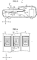
- FIG. 1 is a diagram explaining a keyboard apparatus according to a first embodiment of the present invention.
- a keyboard apparatus 1 is an electronic keyboard instrument.
- the keyboard apparatus 1 is an electronic piano.
- the keyboard apparatus 1 includes a key 10, a casing 50, a speaker 60, a sound source unit 80 and an operation unit 90.
- a side with respect to the keyboard apparatus 1 where a player is present is defined as a front side
- a side opposite to the player is defined as a back side.
- Left, right, and up, and down are also defined as directions when viewed from the player.
- a plurality of keys 10 (a first operating element and a second operating element) is arranged side by side in one direction.
- a scale direction in which the plurality of keys 10 is arranged is referred to as a left-right direction D1 (a first direction).
- a direction perpendicular to the left-right direction D1 is referred to as a front-back direction D2 (a second direction).
- longitudinal direction of the key 10 is the same as the front-back direction D2.
- a direction perpendicular to both the left-right direction D1 and the front-back direction D2 is referred to as a vertical direction D3 (a third direction, see FIG. 2 ).
- the vertical D3 generally corresponds to the vertical direction when the keyboard apparatus 1 is placed flat. That is, when the keyboard apparatus 1 is placed horizontally, the left-right direction D1 and the front-back direction D2 are directions in the horizontal plane.
- the key 10 can rotate with respect to the casing 50.
- a state in which the longitudinal direction of the key 10 coincides with the longitudinal direction of the front-back direction D2 is included in the rotation range of the key 10.
- the speaker 60, a keypress amount measuring unit 70, the sound source unit 80 and the operation unit 90 are arranged in the casing 50.
- the operation unit 90 is a device such as an operation button, a touch sensor and a slider, and receives an instruction for changing the type of the sound (tone) and volume of the sound to be generated, and outputs a signal corresponding to the input operation to the sound source unit 80.
- the keyboard apparatus 1 may include an interface for inputting and outputting signals to and from an external device.
- the interface include a terminal for outputting a sound signal to an external device, and a cable connecting a terminal for transmitting and receiving MIDI data, and the like.
- the keypress amount measuring unit 70 includes a magnetic induction type sensor arranged for each of the plurality of keys 10. Each of the sensors corresponding to each key 10 detects a position (pressing amount) in a rotation range of the key 10.
- the keypress amount measuring unit 70 outputs key information specifying any of the plurality of keys 10 and pressing amount information corresponding to the pressing amount of the specified key 10 to the sound source unit 80.
- the pressing amount information may indicate a value of the pressing amount itself of the key 10, or it may be a value calculated from the pressing amount, such as a speed calculated from a change in the pressing amount, or may be information obtained by combining these.
- the combination of the keypress amount measuring unit 70 and the key 10 is an example of an input device. The detailed configuration of the keypress amount measuring unit 70 will be described later.
- the sound source unit 80 (a generation section) is a signal processing circuit for generating a sound signal according to a performance operation to the key 10. Specifically, the sound source unit 80 generates a sound signal based on the information output from the keypress amount measuring unit 70, and outputs the generated sound signal to the speaker 60. The speaker 60 generates a sound corresponding to the sound signal by amplifying and outputting the sound signal output from the sound source unit 80 .
- FIG. 2 and FIG. 3 schematically showing a cross-section when cutting the keyboard apparatus 1 in a plane having a left-right direction D1 in the normal line (plane including the front-back direction D2 and the vertical direction D3).
- FIG. 2 is a diagram explaining an internal structure of the keyboard apparatus in the first embodiment of the present invention.
- FIG. 3 is a diagram explaining an internal structure of the keyboard apparatus (when a white key is depressed) in the first embodiment of the present invention.
- the keys 10 a configuration corresponding to a white key 10w is shown. Since a configuration corresponding to a black key 10b is the same as the configuration corresponding to the white key 10w, only the position of the black key 10b is shown, and other configurations are omitted.
- a frame 20 is fixed to the casing 50 and supports the plurality of keys 10 arranged in the left-right direction D1.
- the frame 20 is formed of a resin material.
- the frame 20 includes a key guide portion 201, a key support portion 203, a rib portion 205 and a substrate holding portion 207.
- the key guide portion 201 restricts the key 10 from moving in the left-right direction D1 by a member that slides with the key 10 below the front end portion of the key 10.
- the key support portion 203 supports an elastic portion 105 arranged at the rear end portion of the key 10. When the elastic portion 105 is deformed in the vertical direction, a free end side of the key 10 rotates with respect to the key support portion 203. In this case, since the key 10 is restricted from moving in the left-right direction D1 by the key guide portion 201, the key 10 rotates with respect to the left-right direction D1 as a rotation axis.
- the rib portion 205 is a plate-shaped member having a plane including the front-back direction D2 and the vertical direction D3 (surface having the normal line in left-right direction D1).
- a plurality of rib portions 205 is arranged side by side in the left-right direction D1.
- Each of the plurality of rib portions 205 is connected to the key guide portion 201, the key support portion 203, and the substrate holding portion 207.
- a substrate holding portion 207 is a plate-shaped member for holding the active circuit substrate 700 and a magnetic material 780.
- the active circuit substrate 700 is arranged on the upper surface side (a key 10 side) of the substrate holding portion 207
- the magnetic material 780 is arranged on the lower surface side (the side opposite to the key 10) of the substrate holding portion 207.
- a passive circuit substrate 750 is arranged on the lower surface side of the key 10 (the substrate holding portion 207 side). The passive circuit substrate 750 is held on the lower surface side of the key 10 by a holder or the like.
- the active circuit substrate 700 and the passive circuit substrate 750 are, as will be described later, elements constituting the magnetic induction type sensor, which are components included in the keypress amount measuring unit 70 with the magnetic material 780.
- the passive circuit substrate 750 and the magnetic material 780 are provided corresponding to each key 10.
- the active circuit substrate 700 is provided corresponding to the plurality of keys 10, it may be provided corresponding to each key 10.
- Pressing amount information output by the keypress amount measuring unit 70 is information corresponding to a distance between the active circuit substrate 700 and the passive circuit substrate 750.
- the keypress amount measuring unit 70 (a first sensor and a second sensor) includes the active circuit substrate 700, the passive circuit substrate 750 and the magnetic material 780 as described above.
- the active circuit substrate 700 includes a coil (hereinafter referred to as an active coil) for forming a magnetic field by the supplied power.
- an active circuit 770 (see FIG. 4 ) generates anti-resonance according to the position of the passive coil by magnetic coupling. That is, the circuit characteristics of the active circuit 770 change, and the output of the signal obtained from the active circuit substrate 700 changes. Therefore, the distance between the active circuit substrate 700 and the passive circuit substrate 750 can be measured by the signal obtained from the active circuit substrate 700.
- each configuration of the keypress amount measuring unit 70 will be described in detail.
- FIG. 4 is a diagram explaining a passive circuit substrate in a first embodiment of the present invention.
- FIG. 4 shows the passive circuit substrate 750 viewed from below.
- the passive circuit substrate 750 is a printed board including a passive coil 751 and a capacitor 756.
- the passive coil 751 (a first conductor, a second conductor, a third coil, a fourth coil) is formed on a substrate, includes a wiring 751a formed on the lower surface side (the active circuit substrate 700 side) of the substrate and a wiring 751b provided on the upper surface side (the key 10 side) of the substrate, and both ends of which are connected.
- the capacitor 756 is connected in series between both ends of the passive coil 751.
- a surface of the passive circuit substrate 750 (a surface on which the passive coil 751 is formed) is generally parallel to the upper surface of the key 10 (operation surface).
- FIG. 5 is a diagram explaining an active circuit substrate according to the first embodiment of the present invention.
- FIG. 5 illustrates the active circuit substrate 700 viewed from above.
- the active circuit substrate 700 is a printed board including a plurality of active circuits 770, a multiplexer 709 and various wirings (a clock signal line, a select signal line, an input signal line, an output signal line, etc. in addition to a ground wiring 708).
- the active circuit substrate 700 includes a signal processing circuit (not shown).
- Each of the plurality of active circuits 770 is provided corresponding to each key 10. Two wirings connecting the active circuit 770 and the multiplexer 709 correspond to a signal input portion 703a and a signal output portion 703b.
- An active circuit 770 includes an active coil 701, capacitors 706a, 706b, and resistors 707a, 707b.
- the active coil 701 (a first coil, a second coil) is formed on the substrate.
- the active coil 701 includes a wiring 701a formed on the upper surface side (the key 10 side) of the substrate and a wiring 701b provided on the lower surface side (the substrate holding portion 207 side) of the substrate, both ends of which are connected.
- FIG. 5 a configuration arranged on the lower surface of a substrate is shown by a dashed line.
- the capacitors 706a and 706b are connected in series between both ends of the active coil 701.
- a grounding wiring 708 is connected between the capacitor 706a and the capacitor 706b.
- the grounding wiring 708 is provided in common for each active circuit 770.
- the resistor 707a is connected between the capacitor 706a and a signal input portion 703a
- the resistor 707b is connected between the capacitor 706b and a signal output portion 703b.
- the active coil 701 When an AC signal is input to the signal input portion 703a via the multiplexer 709, the active coil 701 forms a magnetic field corresponding to the input signal, and the active coil 701 and a passive coil 751 are magnetically coupled to each other, thereby modulating a signal (a first signal and a second signal) output from the signal output portion 703b.
- the modulated signal is output to a signal processing circuit (not shown) via the multiplexer 709 and converted into pressing amount information.
- the signal processing circuit outputs key information and the pressing amount information of the key 10 corresponding to the signal obtained by the multiplexer 709.
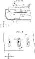
- FIG. 6 is a diagram explaining a positional relationship between the active coil and the magnetic material in the first embodiment of the present invention.
- FIG. 6 shows the positional relationship between the active coil 701 and the magnetic material 780 in the active circuit substrate 700 viewed from above. In order to simply show the positional relationship, illustrations of other components are omitted.
- the magnetic material 780 (a first magnetic material, a second magnetic material) has a rod shape extending in the front-back direction D2, and the positional relationship with the active coil 701 is fixed.
- the adjacent magnetic materials 780 are separated from each other.
- the magnetic material 780 includes a part overlapping the active coil 701 (hereinafter, referred to as an overlapping part OA1) and a part extending from the overlapping part OA1 to the active coil 701 in the front-back direction D2.
- the magnetic material 780 extends from the overlapping part OA1 in both the front direction (corresponding to the front end direction of the key) and the back direction (corresponding to the back end direction of the key), it may extend in only one of the directions.
- a length along the left-right direction D1 of the magnetic material 780 is desirably the same as or even smaller than a length along the left-right direction D1 of the active coil 701.
- the active coil 701 includes the overlapping part OA1 which overlaps with the magnetic material 780 and a part that expands in the left-right direction D1 with respect to the overlapping part OA1.
- the active coil 701 and the magnetic material 780 have a positional relationship as shown in FIG. 6 , the magnetic field formed by the active coil 701 hardly spreads in the left-right direction D1 under the influence of the magnetic material 780. Therefore, as compared with the case when the magnetic material 780 is not arranged, it is possible to reduce the interference due to the magnetic field formed by the respective active coils 701 adjacent to the left-right direction D1.
- FIG. 7 is a diagram explaining a positional relationship between the open magnetic circuit formed by the active coil and the passive coil in the first embodiment of the present invention.
- FIG. 7 further clarifies the positional relationship between the active coil 701 and the magnetic material 780 shown in FIG. 2 and FIG. 3 , and further schematically shows a magnetic flux MF corresponding to the magnetic field formed by the active coil 701.
- the passive coil 751 indicated by a dashed line indicates a position when a key is released (corresponding to FIG. 2 ), and the passive coil 751 indicated by a solid line indicates a position when a key is depressed (corresponding to FIG. 3 ).
- the magnetic flux MF passes through the magnetic material 780 as a magnetic path, and the magnetic flux MF has a path to return from the vicinity of end portions 780a and 780b of the magnetic material 780 to the active coil 701 via the space. As described above, the magnetic material 780 forms an open magnetic circuit with the active coil 701.
- the keyboard apparatus 1 in the first embodiment of the present invention it is possible to measure the pressing amount of the key 10 using the magnetic induction type sensor in the keypress amount measuring unit 70.
- the magnetic material 780 it is possible to control the range of the magnetic field formed by the active coil 701 and reduce the interference between the sensors corresponding to the adjacent keys 10. Therefore, as compared with the case where the magnetic material 780 is not used, it is possible to realize the keyboard apparatus 1 in which the measurement accuracy of the keypress amount is improved.
- FIG. 8 is a diagram explaining an inner structure (when a key is released) of a keyboard apparatus in the second embodiment of the present invention.
- FIG. 9 is a diagram explaining a positional relationship between a passive coil and a magnetic material in the second embodiment of the present invention.
- FIG. 8 is a view corresponding to FIG. 2 and shows the vicinity of the key 10 in an enlarged manner.
- FIG. 9 is a diagram corresponding to FIG. 4 .
- a magnetic material 790 in the second embodiment (a third magnetic material, a fourth magnetic material) has a rod shape extending in the front-back direction D2, and is arranged embedded in the key 10.
- the magnetic material 790 includes a part overlapping the active coil 701 (hereinafter, referred to as an overlapping part OA2), and a part extending from the overlapping part OA2 to the passive coil 751 in the front-back direction D2.
- the magnetic material 790 extends from the overlapping part OA2 in both the front direction (corresponding to the front end direction of the key) and the back direction (corresponding to the back end direction of the key), it may extend in only one of the directions.
- a length along the left-right direction D1 of the magnetic material 790 is desirably the same as or even smaller than a length along the left-right direction D1 of the passive coil 751.
- the passive coil 751 includes the overlapping part OA2 with the magnetic material 790 and a part that expands in the left-right direction D1 with respect to the overlapping part OA2.
- the magnetic flux MF is easily formed so that the magnetic material 790 is used as a magnetic path when the passive coil 751 approaches the active coil 701.
- the magnetic flux MF passing through the passive coil 751 is increased more than in the case where the magnetic material 790 is not used, and it is possible to realize the magnetic coupling more efficiently between the passive coil 751 and the active coil 701. Therefore, as compared with the case of the first embodiment, even if the passive coil 751 is positioned right above the active coil 701, it is possible to effectively utilize the magnetic flux MF. It is also possible to reduce the leakage of the magnetic flux MF upward of the key 10. In addition, by adjusting the size and the weight of the magnetic material 790, it can also be used to adjust the physical touch feeling towards the key 10.
- FIG. 10 is a diagram explaining an active circuit substrate in the third embodiment of the present invention.
- FIG. 11 is a diagram explaining a positional relationship between an open magnetic circuit formed by an active coil and a passive coil in the third embodiment of the present invention.
- FIG. 10 is a diagram corresponding to FIG. 6 and shows an expanded view of the vicinity of the key 10.
- FIG. 11 is a diagram corresponding to FIG. 7 .
- the magnetic material 780A in the third embodiment includes a flat plate portion 780Ar, protrusion parts 780Ata, 780Atb, and a central portion 780Ac.
- the flat plate portion 780Ar has a rectangular parallelepiped shape and is arranged in an active circuit substrate 700A.
- the protrusion parts 780Ata and 780Atb are parts protruding upwards (the key 10 side) at both end portions of the flat plate portion 780Ar and have a rectangular parallelepiped shape. End portions 780Aa, 780Ab of the magnetic material 780A corresponds to the upper side of the protrusion parts 780Ata, 780Atb.
- the central portion 780Ac is a portion protruding upwards (the key 10 side) in the central portion of the flat plate portion 780Ar and has a cylindrical shape.
- An active coil 701A is wound around the central portion 780Ac.
- a part of the magnetic material 780A passes through the internal space of the active coil 701A.
- the active coil 701A is formed by a conductor different from the wiring formed on the active circuit substrate 700A and is connected to a multiplexer 709 (see FIG. 5 ) via the wiring on the active circuit substrate 700A.
- the magnetic flux MF corresponding to the magnetic field formed in the active coil 701A passes through the magnetic material 780A as a magnetic path and has a path to return from the vicinity of end portions 780Aa and 780Ab to the active coil 701A (the central portion 780Ac) via the space.
- the magnetic material 780A forms an open magnetic circuit with the active coil 701A.
- the fourth embodiment instead of the magnetic material 780A of the third embodiment, an example is described in which a magnetic material 780B having a form different from that of the magnetic material 780A is used.
- the fourth embodiment is the same as the third embodiment in that a part of the magnetic material is arranged in the internal space of the active coil.
- this example is a configuration that can be realized even if a part of the magnetic material is arranged between the active coil 701 and the passive coil 751.
- FIG. 12 is a diagram explaining an inner structure of a keyboard apparatus in the fourth embodiment of the present invention.
- FIG. 13 is a diagram explaining an active circuit substrate in the fourth embodiment of the present invention.
- FIG. 14 is a diagram explaining a positional relationship between an open magnetic circuit formed by an active coil and a passive coil in the fourth embodiment of the present invention.
- FIG. 12 is a diagram corresponding to FIG. 2 and shows and expanded view of the vicinity of the key 10.
- FIG. 13 is a diagram corresponding to FIG. 6 .
- FIG. 14 is a diagram corresponding to FIG. 7 .
- the passive circuit substrate 750 in the fourth embodiment is arranged so as to protrude downwards from the key 10. That is, the passive circuit substrate 750 is supported by the key 10 by being partially embedded in the key 10. In this example, the passive circuit substrate 750 is arranged so as to protrude perpendicularly to the surface of the key 10, and in addition, the central axis of the passive coil 751 is arranged so as to face the longitudinal direction of the key 10.
- the magnetic material 780B in the fourth embodiment includes a flat plate portion 780Br, pillar portions 780Bpa, 780Bpb, and an upper plate portion 780Bua, 780Bub.
- the flat plate portion 780Br has a rectangular parallelepiped shape and is arranged in an active circuit substrate 700B.
- the pillar portions 780Bpa and 780Bpb are portions protruding upwards (the key 10 side) at both end portions of the flat plate portion 780Br and have a rectangular parallelepiped shape.
- the upper plate portion 780Bua is a portion extending from the upper end of the pillar portion 780Bpa and has a rectangular parallelepiped shape.
- the upper plate portion 780Bub is a portion extending from the upper end of the pillar portion 780Bpb and has a rectangular parallelepiped shape.
- An end portion 780Ba of the magnetic material 780B is an end portion of the upper plate portion 780Bua opposite to the pillar portion 780Bpa.
- An end portion 780Bb of the magnetic material 780B is an end portion of the upper plate portion 780Bub opposite to the pillar portion 780Bpb.
- the end portion 780Ba and the end portion 780Bb are opposed to each other to form a predetermined space therebetween.
- An active coil 701B is wound around the pillar portion 780Bpb.
- a part of the magnetic material 780B (the pillar portion 780Bpb) passes through the internal space of the active coil 701B.
- the active coil 701B is formed by a conductor different from the wiring formed on the active circuit substrate 700B and is connected to the multiplexer 709 (see FIG. 5 ) via the wiring on the active circuit substrate 700B.
- the magnetic flux MF corresponding to the magnetic field formed in the active coil 701B passes through the magnetic material 780B as a magnetic path and has a path to return from the vicinity of the end portion 780Ba to the end portion 780Bb via the predetermined space.
- the magnetic material 780B forms an open magnetic circuit together with the active coil 701B.
- the active coil 701B may be wound around a portion of the magnetic material 780B other than the pillar portion 780Bpa.
- the passive coil 751 (dashed line) is arranged at a position shifted in the vertical direction D3 with respect to the space between the end portion 780Ba and the end portion 780Bb. Since the passive coil 751 moves downward when a key is depressed, the passive coil 751 moves to a position between the end portion 780Ba and the end portion 780Bb. That is, the distance between the end portion 780Ba (the end portion 780Bb) and the passive coil 751 changes. As described above, when a key is depressed, the passive coil 751 enters the magnetic field which is stronger when a key is depressed than when a key is released.
- the passive coil 751 after the passive coil 751 has entered the position between the end portion 780Ba and the end portion 780Bb, it can also be said that it is not clear which part the distance between the end portion 780Ba (the end portion 780Bb) and the passive coil 751 corresponds to.
- the magnetic material 780A in the third embodiment is tilted by 90 degrees and the side surfaces of the magnetic material 780A are arranged to be parallel to the surface of the substrate.
- FIG. 15 is a diagram explaining an inner structure (when a key is released) of a keyboard apparatus in the fifth embodiment of the present invention.
- FIG. 16 is a diagram explaining a positional relationship between an open magnetic circuit formed by an active coil and a passive coil in the fifth embodiment of the present invention.
- FIG. 15 is a diagram corresponding to FIG. 2 and shows and expanded view of the vicinity of the key 10.
- FIG. 16 is a diagram corresponding to FIG. 6 .
- the passive coil 751 shown by a dashed line in FIG. 6 shows the position of the passive coil 751 when a key is depressed.
- the passive circuit substrate 750 in the fifth embodiment is arranged to protrude downwards from the key 10. That is, the passive circuit substrate 750 is supported by the key 10 by being partially embedded in the key 10. In this example, the passive circuit substrate 750 is arranged so as to protrude perpendicular to the surface of the key 10, and in addition, the central axis of the passive coil 751 is arranged so as to face the scale direction (the left-right direction D1).
- a magnetic field is formed in the left-right direction D1 (left side in FIG. 16 ) with respect to a magnetic material 780C.
- the magnetic flux MF does not expand in the vertical direction D3.
- the passive coil 751 is arranged at a position shifted in the vertical direction D3 with respect to the magnetic material 780C. Since the passive coil 751 moves downwards when a key is depressed, the passive coil 751 moves to a position facing the magnetic material 780C. That is, the distance between an end portion 780Ca of the magnetic material 780C and the passive coil 751 changes. Therefore, the passive coil 751 enters the magnetic field which is stronger when a key is depressed than when a key is released.
- the passive circuit substrate 750 is arranged in a member interlocking with the key 10.
- FIG. 17 is a diagram explaining an inner structure (when a key is released) of a keyboard apparatus in the sixth embodiment of the present invention.
- FIG. 18 is a diagram explaining an inner structure (when a white key is depressed) of a keyboard apparatus in the sixth embodiment of the present invention.
- FIG. 17 is a diagram corresponding to FIG. 2 .
- FIG. 18 is a diagram corresponding to FIG. 3 .
- a keyboard apparatus D1 in the sixth embodiment includes a loaded part 30 arranged corresponding to each key 10D.
- the key 10D is connected to the loaded part 30.
- the key 10D and the load unit 30 are coupled and connected at a key connecting portion 301 (a sliding part 307) of the load unit 30, thereby interlocking with each other.
- the loaded part 30 includes the key connecting portion 301, a bearing 303, and a weight portion 305.
- the bearing 303 is provided corresponding to a shaft portion provided on a frame 20.
- the key connecting portion 301 is arranged on the opposite side of the weight portion 305 with respect to the bearing 303.
- the sliding part 307 provided at one end of the key connecting portion 301 slides against a load connecting part 103 provided below the key 10D.
- the loaded part 30 has a center of gravity present closer to the weight portion 305 than the bearing 303. Therefore, by placing the weight portion 305 on a lower stopper 351 when the key 10D is not depressed, the loaded part 30 holds the key 10 at the rest position (corresponding to when a key is released). When the key 10D is depressed, the weight portion 305 moves upward by rotating the loading portion 30 about the bearing 303, further movement is restricted by colliding with an upper stopper 353.
- the lower stopper 351 and the upper stopper 353 are supported by the frame 20.
- the passive circuit substrate 750 is arranged not in the key 10D but in the loaded part 30 interlocking with the key 10D. Specifically, the passive circuit substrate 750 is arranged on the lower surface of the key connecting portion 301 of the loaded part 30. Therefore, a substrate holding portion 207D, on which the active circuit substrate 700 is arranged, is arranged below the key connecting portion 301.
- the key connecting portion 301 moves downward as shown in FIG. 18 and the active circuit substrate 700 approaches the passive circuit substrate 750.
- the passive circuit substrate 750 can be mounted to a variety of members as long as it is a member that moves in response to a keypress operation.
- the difference between when a key is released and when a key is depressed is larger than the difference in the first embodiment in which the passive circuit substrate 750 is mounted to the key 10. Even if the change in this angle is large, since the amount of magnetic flux passing through the passive coil 751 is changed, there is no problem even in the case of the positional relationship between the passive coil 751 and the active coil 701 as shown in the sixth embodiment.
- an active circuit substrate 700E is described in which the configuration of the active coil 701 is changed without using the magnetic material 780.
- FIG. 19 is a diagram explaining an active circuit substrate in the seventh embodiment of the present invention.
- the active circuit substrate 700E in the seventh embodiment includes an active coil 701E.
- the active coil 701E includes a first active coil 701 Ex and a second active coil 701 Ey.
- the first active coil 701 Ex and the second active coil 701 Ey are arranged side by side along the front-back direction D2, and these winding directions are opposite to each other.
- the fact that the winding direction is opposite does not mean that the wirings are constitutionally wound in the opposite direction, but wound so that the current flows in the opposite direction from each other. Therefore, the magnetic flux formed by the active coil 701E is formed so as to pass through the second active coil 701 Ey immediately after exiting the first active coil 701Ex.
- the configuration corresponding to the magnetic material 780 may be omitted.
- the performance operation apparatus includes an instrument having a sound source unit 80 and outputting a sound signal (the keyboard apparatus 1), and an instrument having a sound generation mechanism for generating a sound
- the performance operation apparatus may include an apparatus that does not output a sound signal (e.g., MIDI controller) and an apparatus that does not generate sound itself (e.g., a pedaling mechanism).
- the key and the pedal are specified as operating elements for the performance operation.
- the performance operation apparatus includes an apparatus that controls the generation of sound and the generation mode of the sound to be changed and outputs a sound signal according to the operation of the operating element by the player (operator) with the head or foot.
- the keypress amount measuring unit 70 may be provided in an input device having operating elements such as a button, a slider, or the like for inputting an instruction from the user.
- the active circuit substrate 700 and the passive circuit substrate 750 may be used to measure the amount of operation on the operating element.
- Such an input device may be provided in a sound signal generation device that generates a sound signal by an operation to an operating element or it may be provided in a device that does not generate a sound signal. That is, it can be said that the key 10 is an example of an operating element for inputting an instruction of a user, the combination of the key 10 and the keypress amount measuring unit 70 is an example of an input device, and the keyboard apparatus 1 is an example of a sound signal generation device.
Landscapes
- Physics & Mathematics (AREA)
- Engineering & Computer Science (AREA)
- Acoustics & Sound (AREA)
- Multimedia (AREA)
- Electromagnetism (AREA)
- Electrophonic Musical Instruments (AREA)
- Input From Keyboards Or The Like (AREA)
- Switches That Are Operated By Magnetic Or Electric Fields (AREA)
Abstract
Description
- The present invention relates to an input device and a sound signal generation device.
- In an electronic keyboard instrument or the like, pressing of a key is detected, and a sound signal is generated based on the detected result. The detection of a key depression is realized by a contact type sensor or a non-contact type sensor. The non-contact type sensor includes, for example, a magnetic induction type sensor (for example, patent literature 1).
- Patent Document 1:
U.S. Patent No. 4580478 - Since a sensor using a magnetic field can be used as a distance sensor, the pressing amount of a key can be measured continuously. On the other hand, since the magnetic field spreads in various directions around a coil, EMC (Electromagnetic Compatibility) countermeasures are required. In addition, when a structure in which a plurality of keys is arranged as in a keyboard instrument is used, sensors corresponding to the plurality of adjacent keys may interfere with each other, and the measurement accuracy may be lowered. Therefore, when a magnetic induction type sensor is used, it was necessary to control the magnetic field formed by the coil according to the purpose of use.
- One object of the present invention is to control the magnetic field formed by the coil of the magnetic induction type sensor.
- According to an embodiment of the present invention, an input device is provided including a first operating element and a first sensor. The first sensor includes a first conductor, a first coil, and a first magnetic material forming an open magnetic circuit together with the first coil. A positional relationship between the first coil and the first magnetic material is fixed. A first distance between a first end portion of the first magnetic material and the first conductor varies according to the amount of operation on the first operating element. The first sensor outputs a first signal corresponding to the first distance.
- The input device may further include a second operating element and a second sensor. The second operating element is adjacent to the first operating element in a first direction. The second sensor includes a second conductor, a second coil, and a second magnetic material forming an open magnetic circuit together with the second coil. The second magnetic material has a second portion extending in a second direction different from the first direction with respect to the second coil. A positional relationship between the second coil and the second magnetic material is fixed. The second magnetic material is separated from the first magnetic material. A second distance between a second end portion on a second portion side of the second magnetic material and the second conductor varies according to the amount of operation on the second operating element. The second sensor outputs a second signal corresponding to the second distance. The first magnetic material has a first portion extending in the second direction with respect to the first coil. The first end portion may be an end portion on a first portion side of the first magnetic material.
- The first conductor may be interlocked with the first operating element.
- The first conductor may include a third coil.
- A part of the first magnetic material may pass through the internal space of the first coil.
- The first coil may be formed on a substrate, and the first coil may be arranged between at least a part of the first magnetic material and the first conductor at any one position in a range of movement of the first operating element.
- According to an embodiment of the present invention, an input device is provided including a first operating element and a first sensor. The first sensor includes a first coil, a third coil, and a third magnetic material. The third coil is arranged between the first coil and the third magnetic material at any one position in a range of movement of the first operating element. A positional relationship between the third coil and the third magnetic material is fixed. The first distance between the first coil and the third coil varies according to the amount of operation on the first operating element. The first sensor outputs the first signal corresponding to the first distance.
- The input device may further include a second operating element and a second sensor. The second operating element is adjacent to the first operating element in a first direction. The second sensor includes a second coil, a fourth coil, and a fourth magnetic material, the second coil and the fourth coil having a part in which winding directions are opposite to each other. The fourth coil is arranged between the second coil and the fourth magnetic material at any one position in a range of movement of the second operating element. A positional relationship between the fourth coil and the fourth magnetic material is fixed. The fourth magnetic material is separated from the third magnetic material. The first distance between the second coil and the fourth coil varies according to the amount of operation on the second operating element. The second sensor outputs a second signal corresponding to the second distance. The first coil may have a part in which the winding directions are opposite to each other.
- In the first coil and the second coil, parts in which winding directions are opposite to each other may be aligned in the second direction different from the first direction.
- The first operating element and the second operating element may have a longitudinal shape in the second direction.
- According to an embodiment of the present invention, a sound signal generation device is provided including the input device described above and a generation unit configured to generate a sound signal based on the first signal and the second signal.
- According to an embodiment of the present invention, it is possible to control a magnetic field formed by a coil of a magnetic induction type sensor.
-
-
FIG. 1 is a diagram explaining a keyboard apparatus in a first embodiment of the present invention. -
FIG. 2 is a diagram explaining an inner structure (when a key is released) of a keyboard apparatus in the first embodiment of the present invention. -
FIG. 3 is a diagram explaining an inner structure (when a white key is depressed) of a keyboard apparatus in the first embodiment of the present invention. -
FIG. 4 is a diagram explaining a passive circuit substrate in the first embodiment of the present invention. -
FIG. 5 is a diagram explaining an active circuit substrate in the first embodiment of the present invention. -
FIG. 6 is a diagram explaining a positional relationship between an active coil and a magnetic material in the first embodiment of the present invention. -
FIG. 7 is a diagram explaining a positional relationship between an open magnetic circuit formed by the active coil and a passive coil in the first embodiment of the present invention. -
FIG. 8 is a diagram explaining an inner structure (when a key is released) of a keyboard apparatus in a second embodiment of the present invention. -
FIG. 9 is a diagram explaining a positional relationship between a passive coil and a magnetic material in the second embodiment of the present invention. -
FIG. 10 is a diagram explaining an active circuit substrate in a third embodiment of the present invention. -
FIG. 11 is a diagram explaining a positional relationship between an open magnetic circuit formed by an active coil and a passive coil in the third embodiment of the present invention. -
FIG. 12 is a diagram explaining an inner structure (when a key is released) of a keyboard apparatus in a fourth embodiment of the present invention. -
FIG. 13 is a diagram explaining an active circuit substrate in the fourth embodiment of the present invention. -
FIG. 14 is a diagram explaining a positional relationship between an open magnetic circuit formed by an active coil and a passive coil in the fourth embodiment of the present invention. -
FIG. 15 is a diagram explaining an inner structure (when a key is released) of a keyboard apparatus in a fifth embodiment of the present invention. -
FIG. 16 is a diagram explaining a positional relationship between an open magnetic circuit formed by an active coil and a passive coil in the fifth embodiment of the present invention. -
FIG. 17 is a diagram explaining an inner structure (when a key is released) of a keyboard apparatus in a sixth embodiment of the present invention. -
FIG. 18 is a diagram explaining an inner structure (when a white key is depressed) of a keyboard apparatus in the sixth embodiment of the present invention. -
FIG. 19 is a diagram explaining an active circuit substrate in a seventh embodiment of the present invention. - Hereinafter, a keyboard apparatus in an embodiment of the present invention will be described in detail with reference to the drawings. The following embodiments are examples of embodiments of the present invention, and the present invention should not be construed as being limited to these embodiments. In addition, in the drawings referred to in the present embodiment, the same portions or portions having similar functions are denoted by the same symbols or similar symbols (A, B, etc. denoted after numerals), and a repetitive description thereof may be omitted. Dimensional ratios in the drawings may differ from actual ratios for convenience of description, or some of the configurations may be omitted from the drawings.
- In the first embodiment, a keyboard apparatus used as an electronic keyboard instrument will be described. According to this keyboard apparatus, the keypress operation can be detected by a magnetic induction type sensor. Hereinafter, the keyboard apparatus will be described in detail.
-
FIG. 1 is a diagram explaining a keyboard apparatus according to a first embodiment of the present invention. Akeyboard apparatus 1 is an electronic keyboard instrument. In this example, thekeyboard apparatus 1 is an electronic piano. Thekeyboard apparatus 1 includes a key 10, acasing 50, aspeaker 60, asound source unit 80 and anoperation unit 90. In the following description, for convenience of description, a side with respect to thekeyboard apparatus 1 where a player is present (a side on which the key 10 is present with respect to the casing 50) is defined as a front side, and a side opposite to the player is defined as a back side. Left, right, and up, and down are also defined as directions when viewed from the player. - A plurality of keys 10 (a first operating element and a second operating element) is arranged side by side in one direction. Here, a scale direction in which the plurality of
keys 10 is arranged is referred to as a left-right direction D1 (a first direction). A direction perpendicular to the left-right direction D1 is referred to as a front-back direction D2 (a second direction). When thekeyboard apparatus 1 is viewed from above, longitudinal direction of the key 10 is the same as the front-back direction D2. A direction perpendicular to both the left-right direction D1 and the front-back direction D2 is referred to as a vertical direction D3 (a third direction, seeFIG. 2 ). The vertical D3 generally corresponds to the vertical direction when thekeyboard apparatus 1 is placed flat. That is, when thekeyboard apparatus 1 is placed horizontally, the left-right direction D1 and the front-back direction D2 are directions in the horizontal plane. - The key 10 can rotate with respect to the
casing 50. A state in which the longitudinal direction of the key 10 coincides with the longitudinal direction of the front-back direction D2 is included in the rotation range of the key 10. Thespeaker 60, a keypressamount measuring unit 70, thesound source unit 80 and theoperation unit 90 are arranged in thecasing 50. When a user operates the key 10, a sound is generated from thespeaker 60 by a sound generation function of thekeyboard apparatus 1. Theoperation unit 90 is a device such as an operation button, a touch sensor and a slider, and receives an instruction for changing the type of the sound (tone) and volume of the sound to be generated, and outputs a signal corresponding to the input operation to thesound source unit 80. In addition, thekeyboard apparatus 1 may include an interface for inputting and outputting signals to and from an external device. Examples of the interface include a terminal for outputting a sound signal to an external device, and a cable connecting a terminal for transmitting and receiving MIDI data, and the like. - The keypress
amount measuring unit 70 includes a magnetic induction type sensor arranged for each of the plurality ofkeys 10. Each of the sensors corresponding to each key 10 detects a position (pressing amount) in a rotation range of the key 10. The keypressamount measuring unit 70 outputs key information specifying any of the plurality ofkeys 10 and pressing amount information corresponding to the pressing amount of the specified key 10 to thesound source unit 80. The pressing amount information may indicate a value of the pressing amount itself of the key 10, or it may be a value calculated from the pressing amount, such as a speed calculated from a change in the pressing amount, or may be information obtained by combining these. The combination of the keypressamount measuring unit 70 and the key 10 is an example of an input device. The detailed configuration of the keypressamount measuring unit 70 will be described later. - The sound source unit 80 (a generation section) is a signal processing circuit for generating a sound signal according to a performance operation to the key 10. Specifically, the
sound source unit 80 generates a sound signal based on the information output from the keypressamount measuring unit 70, and outputs the generated sound signal to thespeaker 60. Thespeaker 60 generates a sound corresponding to the sound signal by amplifying and outputting the sound signal output from thesound source unit 80 . - Next, an internal structure of the
keyboard apparatus 1 will be described. Here, an internal structure of thekeyboard apparatus 1 will be described with reference toFIG. 2 andFIG. 3 schematically showing a cross-section when cutting thekeyboard apparatus 1 in a plane having a left-right direction D1 in the normal line (plane including the front-back direction D2 and the vertical direction D3). -
FIG. 2 is a diagram explaining an internal structure of the keyboard apparatus in the first embodiment of the present invention.FIG. 3 is a diagram explaining an internal structure of the keyboard apparatus (when a white key is depressed) in the first embodiment of the present invention. Among thekeys 10, a configuration corresponding to a white key 10w is shown. Since a configuration corresponding to a black key 10b is the same as the configuration corresponding to the white key 10w, only the position of the black key 10b is shown, and other configurations are omitted. - A
frame 20 is fixed to thecasing 50 and supports the plurality ofkeys 10 arranged in the left-right direction D1. In this example, theframe 20 is formed of a resin material. Theframe 20 includes akey guide portion 201, akey support portion 203, arib portion 205 and asubstrate holding portion 207. - The
key guide portion 201 restricts the key 10 from moving in the left-right direction D1 by a member that slides with the key 10 below the front end portion of the key 10. Thekey support portion 203 supports anelastic portion 105 arranged at the rear end portion of the key 10. When theelastic portion 105 is deformed in the vertical direction, a free end side of the key 10 rotates with respect to thekey support portion 203. In this case, since the key 10 is restricted from moving in the left-right direction D1 by thekey guide portion 201, the key 10 rotates with respect to the left-right direction D1 as a rotation axis. Therib portion 205 is a plate-shaped member having a plane including the front-back direction D2 and the vertical direction D3 (surface having the normal line in left-right direction D1). A plurality ofrib portions 205 is arranged side by side in the left-right direction D1. Each of the plurality ofrib portions 205 is connected to thekey guide portion 201, thekey support portion 203, and thesubstrate holding portion 207. - A
substrate holding portion 207 is a plate-shaped member for holding theactive circuit substrate 700 and amagnetic material 780. In this example, theactive circuit substrate 700 is arranged on the upper surface side (a key 10 side) of thesubstrate holding portion 207, and themagnetic material 780 is arranged on the lower surface side (the side opposite to the key 10) of thesubstrate holding portion 207. Apassive circuit substrate 750 is arranged on the lower surface side of the key 10 (thesubstrate holding portion 207 side). Thepassive circuit substrate 750 is held on the lower surface side of the key 10 by a holder or the like. - The
active circuit substrate 700 and thepassive circuit substrate 750 are, as will be described later, elements constituting the magnetic induction type sensor, which are components included in the keypressamount measuring unit 70 with themagnetic material 780. Thepassive circuit substrate 750 and themagnetic material 780 are provided corresponding to each key 10. In this example, although theactive circuit substrate 700 is provided corresponding to the plurality ofkeys 10, it may be provided corresponding to each key 10. - When the key 10 is depressed in the state shown in
FIG. 2 , theactive circuit substrate 700 approaches thepassive circuit substrate 750 as shown inFIG. 3 . Pressing amount information output by the keypressamount measuring unit 70 is information corresponding to a distance between theactive circuit substrate 700 and thepassive circuit substrate 750. - The keypress amount measuring unit 70 (a first sensor and a second sensor) includes the
active circuit substrate 700, thepassive circuit substrate 750 and themagnetic material 780 as described above. Theactive circuit substrate 700 includes a coil (hereinafter referred to as an active coil) for forming a magnetic field by the supplied power. When thepassive circuit substrate 750 including the coil (hereinafter, referred to as a passive coil) moves in the magnetic field, an active circuit 770 (seeFIG. 4 ) generates anti-resonance according to the position of the passive coil by magnetic coupling. That is, the circuit characteristics of theactive circuit 770 change, and the output of the signal obtained from theactive circuit substrate 700 changes. Therefore, the distance between theactive circuit substrate 700 and thepassive circuit substrate 750 can be measured by the signal obtained from theactive circuit substrate 700. Hereinafter, each configuration of the keypressamount measuring unit 70 will be described in detail. -
FIG. 4 is a diagram explaining a passive circuit substrate in a first embodiment of the present invention.FIG. 4 shows thepassive circuit substrate 750 viewed from below. Thepassive circuit substrate 750 is a printed board including apassive coil 751 and acapacitor 756. The passive coil 751 (a first conductor, a second conductor, a third coil, a fourth coil) is formed on a substrate, includes awiring 751a formed on the lower surface side (theactive circuit substrate 700 side) of the substrate and awiring 751b provided on the upper surface side (the key 10 side) of the substrate, and both ends of which are connected. Thecapacitor 756 is connected in series between both ends of thepassive coil 751. In this example, a surface of the passive circuit substrate 750 (a surface on which thepassive coil 751 is formed) is generally parallel to the upper surface of the key 10 (operation surface). -
FIG. 5 is a diagram explaining an active circuit substrate according to the first embodiment of the present invention.FIG. 5 illustrates theactive circuit substrate 700 viewed from above. Theactive circuit substrate 700 is a printed board including a plurality ofactive circuits 770, amultiplexer 709 and various wirings (a clock signal line, a select signal line, an input signal line, an output signal line, etc. in addition to a ground wiring 708). Also, theactive circuit substrate 700 includes a signal processing circuit (not shown). Each of the plurality ofactive circuits 770 is provided corresponding to each key 10. Two wirings connecting theactive circuit 770 and themultiplexer 709 correspond to a signal input portion 703a and asignal output portion 703b. - An
active circuit 770 includes anactive coil 701,capacitors 706a, 706b, andresistors active coil 701 includes awiring 701a formed on the upper surface side (the key 10 side) of the substrate and awiring 701b provided on the lower surface side (thesubstrate holding portion 207 side) of the substrate, both ends of which are connected. InFIG. 5 , a configuration arranged on the lower surface of a substrate is shown by a dashed line. Thecapacitors 706a and 706b are connected in series between both ends of theactive coil 701. Agrounding wiring 708 is connected between the capacitor 706a and thecapacitor 706b. Thegrounding wiring 708 is provided in common for eachactive circuit 770. Theresistor 707a is connected between the capacitor 706a and a signal input portion 703a, and theresistor 707b is connected between thecapacitor 706b and asignal output portion 703b. - When an AC signal is input to the signal input portion 703a via the
multiplexer 709, theactive coil 701 forms a magnetic field corresponding to the input signal, and theactive coil 701 and apassive coil 751 are magnetically coupled to each other, thereby modulating a signal (a first signal and a second signal) output from thesignal output portion 703b. The modulated signal is output to a signal processing circuit (not shown) via themultiplexer 709 and converted into pressing amount information. The signal processing circuit outputs key information and the pressing amount information of the key 10 corresponding to the signal obtained by themultiplexer 709. -
FIG. 6 is a diagram explaining a positional relationship between the active coil and the magnetic material in the first embodiment of the present invention.FIG. 6 shows the positional relationship between theactive coil 701 and themagnetic material 780 in theactive circuit substrate 700 viewed from above. In order to simply show the positional relationship, illustrations of other components are omitted. - As shown in
FIG. 6 , the magnetic material 780 (a first magnetic material, a second magnetic material) has a rod shape extending in the front-back direction D2, and the positional relationship with theactive coil 701 is fixed. The adjacentmagnetic materials 780 are separated from each other. Themagnetic material 780 includes a part overlapping the active coil 701 (hereinafter, referred to as an overlapping part OA1) and a part extending from the overlapping part OA1 to theactive coil 701 in the front-back direction D2. In this example, although themagnetic material 780 extends from the overlapping part OA1 in both the front direction (corresponding to the front end direction of the key) and the back direction (corresponding to the back end direction of the key), it may extend in only one of the directions. - A length along the left-right direction D1 of the
magnetic material 780 is desirably the same as or even smaller than a length along the left-right direction D1 of theactive coil 701. In this example, theactive coil 701 includes the overlapping part OA1 which overlaps with themagnetic material 780 and a part that expands in the left-right direction D1 with respect to the overlapping part OA1. - Since the
active coil 701 and themagnetic material 780 have a positional relationship as shown inFIG. 6 , the magnetic field formed by theactive coil 701 hardly spreads in the left-right direction D1 under the influence of themagnetic material 780. Therefore, as compared with the case when themagnetic material 780 is not arranged, it is possible to reduce the interference due to the magnetic field formed by the respectiveactive coils 701 adjacent to the left-right direction D1. -
FIG. 7 is a diagram explaining a positional relationship between the open magnetic circuit formed by the active coil and the passive coil in the first embodiment of the present invention.FIG. 7 further clarifies the positional relationship between theactive coil 701 and themagnetic material 780 shown inFIG. 2 andFIG. 3 , and further schematically shows a magnetic flux MF corresponding to the magnetic field formed by theactive coil 701. Thepassive coil 751 indicated by a dashed line indicates a position when a key is released (corresponding toFIG. 2 ), and thepassive coil 751 indicated by a solid line indicates a position when a key is depressed (corresponding toFIG. 3 ). The magnetic flux MF passes through themagnetic material 780 as a magnetic path, and the magnetic flux MF has a path to return from the vicinity ofend portions magnetic material 780 to theactive coil 701 via the space. As described above, themagnetic material 780 forms an open magnetic circuit with theactive coil 701. - When the
passive coil 751 moves in the magnetic flux MF, an induced current corresponding to the density of the magnetic flux MF passing through thepassive coil 751 at that position occurs in thepassive coil 751, and an output signal from theactive circuit substrate 700 obtained via theactive coil 701 is changed. In other words, it can be said that the output signal changes according to the distance between theactive coil 701 and thepassive coil 751 or changes according to the distance between theend portion 780a of themagnetic material 780 and thepassive coil 751. Also, in this example, a positional relationship is realized whereby theactive coil 701 is arranged between thepassive coil 751 and at least a part of themagnetic material 780, and themagnetic material 780 is not arranged between theactive coil 701 and thepassive coil 751. This positional relationship may be realized when the key 10 is present in at least any one range in a range of movement. The above explanation is the description of the structure of the keypressamount measuring unit 70. - As described above, according to the
keyboard apparatus 1 in the first embodiment of the present invention, it is possible to measure the pressing amount of the key 10 using the magnetic induction type sensor in the keypressamount measuring unit 70. In this case, by arranging themagnetic material 780, it is possible to control the range of the magnetic field formed by theactive coil 701 and reduce the interference between the sensors corresponding to theadjacent keys 10. Therefore, as compared with the case where themagnetic material 780 is not used, it is possible to realize thekeyboard apparatus 1 in which the measurement accuracy of the keypress amount is improved. - In the second embodiment, an example is described in which a magnetic material corresponding to the
passive circuit substrate 750 is further provided in the first embodiment. -
FIG. 8 is a diagram explaining an inner structure (when a key is released) of a keyboard apparatus in the second embodiment of the present invention.FIG. 9 is a diagram explaining a positional relationship between a passive coil and a magnetic material in the second embodiment of the present invention.FIG. 8 is a view corresponding toFIG. 2 and shows the vicinity of the key 10 in an enlarged manner.FIG. 9 is a diagram corresponding toFIG. 4 . Amagnetic material 790 in the second embodiment (a third magnetic material, a fourth magnetic material) has a rod shape extending in the front-back direction D2, and is arranged embedded in the key 10. Themagnetic material 790 includes a part overlapping the active coil 701 (hereinafter, referred to as an overlapping part OA2), and a part extending from the overlapping part OA2 to thepassive coil 751 in the front-back direction D2. In this example, although themagnetic material 790 extends from the overlapping part OA2 in both the front direction (corresponding to the front end direction of the key) and the back direction (corresponding to the back end direction of the key), it may extend in only one of the directions. - Also, a length along the left-right direction D1 of the
magnetic material 790 is desirably the same as or even smaller than a length along the left-right direction D1 of thepassive coil 751. In this example, thepassive coil 751 includes the overlapping part OA2 with themagnetic material 790 and a part that expands in the left-right direction D1 with respect to the overlapping part OA2. - As described above, by providing the
magnetic material 790 also in thepassive coil 751 side, the magnetic flux MF is easily formed so that themagnetic material 790 is used as a magnetic path when thepassive coil 751 approaches theactive coil 701. As a result, the magnetic flux MF passing through thepassive coil 751 is increased more than in the case where themagnetic material 790 is not used, and it is possible to realize the magnetic coupling more efficiently between thepassive coil 751 and theactive coil 701. Therefore, as compared with the case of the first embodiment, even if thepassive coil 751 is positioned right above theactive coil 701, it is possible to effectively utilize the magnetic flux MF. It is also possible to reduce the leakage of the magnetic flux MF upward of the key 10. In addition, by adjusting the size and the weight of themagnetic material 790, it can also be used to adjust the physical touch feeling towards the key 10. - In the third embodiment, instead of the
magnetic material 780 of the first embodiment, an example is described in which amagnetic material 780A having a shape different from that of themagnetic material 780 is used. -
FIG. 10 is a diagram explaining an active circuit substrate in the third embodiment of the present invention.FIG. 11 is a diagram explaining a positional relationship between an open magnetic circuit formed by an active coil and a passive coil in the third embodiment of the present invention.FIG. 10 is a diagram corresponding toFIG. 6 and shows an expanded view of the vicinity of the key 10.FIG. 11 is a diagram corresponding toFIG. 7 . - The
magnetic material 780A in the third embodiment includes a flat plate portion 780Ar, protrusion parts 780Ata, 780Atb, and a central portion 780Ac. The flat plate portion 780Ar has a rectangular parallelepiped shape and is arranged in anactive circuit substrate 700A. The protrusion parts 780Ata and 780Atb are parts protruding upwards (the key 10 side) at both end portions of the flat plate portion 780Ar and have a rectangular parallelepiped shape. End portions 780Aa, 780Ab of themagnetic material 780A corresponds to the upper side of the protrusion parts 780Ata, 780Atb. The central portion 780Ac is a portion protruding upwards (the key 10 side) in the central portion of the flat plate portion 780Ar and has a cylindrical shape. - An
active coil 701A is wound around the central portion 780Ac. In other words, a part of themagnetic material 780A (the central portion 780Ac) passes through the internal space of theactive coil 701A. Theactive coil 701A is formed by a conductor different from the wiring formed on theactive circuit substrate 700A and is connected to a multiplexer 709 (seeFIG. 5 ) via the wiring on theactive circuit substrate 700A. As shown inFIG. 11 , the magnetic flux MF corresponding to the magnetic field formed in theactive coil 701A passes through themagnetic material 780A as a magnetic path and has a path to return from the vicinity of end portions 780Aa and 780Ab to theactive coil 701A (the central portion 780Ac) via the space. Also in this embodiment, themagnetic material 780A forms an open magnetic circuit with theactive coil 701A. - In the fourth embodiment, instead of the
magnetic material 780A of the third embodiment, an example is described in which amagnetic material 780B having a form different from that of themagnetic material 780A is used. The fourth embodiment is the same as the third embodiment in that a part of the magnetic material is arranged in the internal space of the active coil. In addition, unlike the third embodiment, this example is a configuration that can be realized even if a part of the magnetic material is arranged between theactive coil 701 and thepassive coil 751. -
FIG. 12 is a diagram explaining an inner structure of a keyboard apparatus in the fourth embodiment of the present invention.FIG. 13 is a diagram explaining an active circuit substrate in the fourth embodiment of the present invention.FIG. 14 is a diagram explaining a positional relationship between an open magnetic circuit formed by an active coil and a passive coil in the fourth embodiment of the present invention.FIG. 12 is a diagram corresponding toFIG. 2 and shows and expanded view of the vicinity of the key 10.FIG. 13 is a diagram corresponding toFIG. 6 .FIG. 14 is a diagram corresponding toFIG. 7 . - The
passive circuit substrate 750 in the fourth embodiment is arranged so as to protrude downwards from the key 10. That is, thepassive circuit substrate 750 is supported by the key 10 by being partially embedded in the key 10. In this example, thepassive circuit substrate 750 is arranged so as to protrude perpendicularly to the surface of the key 10, and in addition, the central axis of thepassive coil 751 is arranged so as to face the longitudinal direction of the key 10. - The
magnetic material 780B in the fourth embodiment includes a flat plate portion 780Br, pillar portions 780Bpa, 780Bpb, and an upper plate portion 780Bua, 780Bub. The flat plate portion 780Br has a rectangular parallelepiped shape and is arranged in anactive circuit substrate 700B. The pillar portions 780Bpa and 780Bpb are portions protruding upwards (the key 10 side) at both end portions of the flat plate portion 780Br and have a rectangular parallelepiped shape. The upper plate portion 780Bua is a portion extending from the upper end of the pillar portion 780Bpa and has a rectangular parallelepiped shape. The upper plate portion 780Bub is a portion extending from the upper end of the pillar portion 780Bpb and has a rectangular parallelepiped shape. - An end portion 780Ba of the
magnetic material 780B is an end portion of the upper plate portion 780Bua opposite to the pillar portion 780Bpa. An end portion 780Bb of themagnetic material 780B is an end portion of the upper plate portion 780Bub opposite to the pillar portion 780Bpb. The end portion 780Ba and the end portion 780Bb are opposed to each other to form a predetermined space therebetween. - An
active coil 701B is wound around the pillar portion 780Bpb. In other words, a part of themagnetic material 780B (the pillar portion 780Bpb) passes through the internal space of theactive coil 701B. Theactive coil 701B is formed by a conductor different from the wiring formed on theactive circuit substrate 700B and is connected to the multiplexer 709 (seeFIG. 5 ) via the wiring on theactive circuit substrate 700B. As shown inFIG. 14 , the magnetic flux MF corresponding to the magnetic field formed in theactive coil 701B passes through themagnetic material 780B as a magnetic path and has a path to return from the vicinity of the end portion 780Ba to the end portion 780Bb via the predetermined space. Also in this example, themagnetic material 780B forms an open magnetic circuit together with theactive coil 701B. Theactive coil 701B may be wound around a portion of themagnetic material 780B other than the pillar portion 780Bpa. - As shown in
FIG. 14 , when a key is released, the passive coil 751 (dashed line) is arranged at a position shifted in the vertical direction D3 with respect to the space between the end portion 780Ba and the end portion 780Bb. Since thepassive coil 751 moves downward when a key is depressed, thepassive coil 751 moves to a position between the end portion 780Ba and the end portion 780Bb. That is, the distance between the end portion 780Ba (the end portion 780Bb) and thepassive coil 751 changes. As described above, when a key is depressed, thepassive coil 751 enters the magnetic field which is stronger when a key is depressed than when a key is released. Also, after thepassive coil 751 has entered the position between the end portion 780Ba and the end portion 780Bb, it can also be said that it is not clear which part the distance between the end portion 780Ba (the end portion 780Bb) and thepassive coil 751 corresponds to. Here, it is defined that the larger the area of thepassive coil 751 entering the space between the end portion 780Ba and the end portion 780Bb, the smaller the distance between the end portion 780Ba (the end portion 780Bb) and thepassive coil 751. - In the fifth embodiment, an example is described in which the
magnetic material 780A in the third embodiment is tilted by 90 degrees and the side surfaces of themagnetic material 780A are arranged to be parallel to the surface of the substrate. -
FIG. 15 is a diagram explaining an inner structure (when a key is released) of a keyboard apparatus in the fifth embodiment of the present invention.FIG. 16 is a diagram explaining a positional relationship between an open magnetic circuit formed by an active coil and a passive coil in the fifth embodiment of the present invention.FIG. 15 is a diagram corresponding toFIG. 2 and shows and expanded view of the vicinity of the key 10.FIG. 16 is a diagram corresponding toFIG. 6 . Also, thepassive coil 751 shown by a dashed line inFIG. 6 shows the position of thepassive coil 751 when a key is depressed. - The
passive circuit substrate 750 in the fifth embodiment is arranged to protrude downwards from the key 10. That is, thepassive circuit substrate 750 is supported by the key 10 by being partially embedded in the key 10. In this example, thepassive circuit substrate 750 is arranged so as to protrude perpendicular to the surface of the key 10, and in addition, the central axis of thepassive coil 751 is arranged so as to face the scale direction (the left-right direction D1). - As shown in
FIG. 16 , a magnetic field is formed in the left-right direction D1 (left side inFIG. 16 ) with respect to amagnetic material 780C. As described above, since the magnetic path is restricted by themagnetic material 780C, the magnetic flux MF does not expand in the vertical direction D3. When a key is released, as shown inFIG. 15 , thepassive coil 751 is arranged at a position shifted in the vertical direction D3 with respect to themagnetic material 780C. Since thepassive coil 751 moves downwards when a key is depressed, thepassive coil 751 moves to a position facing themagnetic material 780C. That is, the distance between an end portion 780Ca of themagnetic material 780C and thepassive coil 751 changes. Therefore, thepassive coil 751 enters the magnetic field which is stronger when a key is depressed than when a key is released. - In the sixth embodiment, an example is described in which the
passive circuit substrate 750 is arranged in a member interlocking with the key 10. -
FIG. 17 is a diagram explaining an inner structure (when a key is released) of a keyboard apparatus in the sixth embodiment of the present invention.FIG. 18 is a diagram explaining an inner structure (when a white key is depressed) of a keyboard apparatus in the sixth embodiment of the present invention.FIG. 17 is a diagram corresponding toFIG. 2 .FIG. 18 is a diagram corresponding toFIG. 3 . A keyboard apparatus D1 in the sixth embodiment includes a loadedpart 30 arranged corresponding to each key 10D. The key 10D is connected to the loadedpart 30. As a result, the key 10D and theload unit 30 are coupled and connected at a key connecting portion 301 (a sliding part 307) of theload unit 30, thereby interlocking with each other. - The
loaded part 30 includes thekey connecting portion 301, abearing 303, and aweight portion 305. Thebearing 303 is provided corresponding to a shaft portion provided on aframe 20. Thekey connecting portion 301 is arranged on the opposite side of theweight portion 305 with respect to thebearing 303. The slidingpart 307 provided at one end of thekey connecting portion 301 slides against aload connecting part 103 provided below the key 10D. Theloaded part 30 has a center of gravity present closer to theweight portion 305 than thebearing 303. Therefore, by placing theweight portion 305 on alower stopper 351 when the key 10D is not depressed, theloaded part 30 holds the key 10 at the rest position (corresponding to when a key is released). When the key 10D is depressed, theweight portion 305 moves upward by rotating theloading portion 30 about thebearing 303, further movement is restricted by colliding with anupper stopper 353. Thelower stopper 351 and theupper stopper 353 are supported by theframe 20. - In this example, the
passive circuit substrate 750 is arranged not in the key 10D but in the loadedpart 30 interlocking with the key 10D. Specifically, thepassive circuit substrate 750 is arranged on the lower surface of thekey connecting portion 301 of the loadedpart 30. Therefore, asubstrate holding portion 207D, on which theactive circuit substrate 700 is arranged, is arranged below thekey connecting portion 301. When the key 10 is depressed in the state shown inFIG. 17 , thekey connecting portion 301 moves downward as shown inFIG. 18 and theactive circuit substrate 700 approaches thepassive circuit substrate 750. As described above, thepassive circuit substrate 750 can be mounted to a variety of members as long as it is a member that moves in response to a keypress operation. - Also, with respect to the angle between the
passive circuit substrate 750 and theactive circuit substrate 700, the difference between when a key is released and when a key is depressed is larger than the difference in the first embodiment in which thepassive circuit substrate 750 is mounted to the key 10. Even if the change in this angle is large, since the amount of magnetic flux passing through thepassive coil 751 is changed, there is no problem even in the case of the positional relationship between thepassive coil 751 and theactive coil 701 as shown in the sixth embodiment. - In the seventh embodiment, an
active circuit substrate 700E is described in which the configuration of theactive coil 701 is changed without using themagnetic material 780. -
FIG. 19 is a diagram explaining an active circuit substrate in the seventh embodiment of the present invention. Theactive circuit substrate 700E in the seventh embodiment includes anactive coil 701E. Theactive coil 701E includes a firstactive coil 701 Ex and a secondactive coil 701 Ey. The firstactive coil 701 Ex and the secondactive coil 701 Ey are arranged side by side along the front-back direction D2, and these winding directions are opposite to each other. The fact that the winding direction is opposite does not mean that the wirings are constitutionally wound in the opposite direction, but wound so that the current flows in the opposite direction from each other. Therefore, the magnetic flux formed by theactive coil 701E is formed so as to pass through the secondactive coil 701 Ey immediately after exiting the first active coil 701Ex. - In this way, it is also possible to prevent the magnetic fields formed by the adjacent
active coils 701E from interfering with each other. Therefore, in this case, the configuration corresponding to themagnetic material 780 may be omitted. In this example, it is desirable to adopt a configuration using themagnetic material 790 as in the second embodiment for thepassive circuit substrate 750. - While an embodiment of the present invention has been described above, an embodiment of the present invention may be modified into various forms as follows. Also, the embodiments described above and the modifications described below can be applied in combination with each other. Further, it is possible to add, delete, or replace another configuration with respect to a part of the configuration of each embodiment. In the following description, although an example of modifying the first embodiment will be described, other embodiments may also be applied as a modified example.
- (1) Although the
passive coil 751 is provided in thepassive circuit substrate 750, a metal plate may be provided instead of thepassive coil 751. Even with this configuration, modulation of the output signal of theactive circuit 770 can be realized by the eddy current generated in the metal plate as in thepassive coil 751. That is, in thepassive circuit substrate 750, instead of the coil, a conductor such as a metal plate or the like capable of absorbing energy through a magnetic field may be arranged. - (2) In the first embodiment, the
active coil 701 is arranged on theframe 20 side, and thepassive coil 751 is arranged on the key 10 side. Since thepassive coil 751 does not require a power supply or the like, although it is easy to design a structure where it is provided on the structure having a movable portion, it is also possible to be arranged in the reverse relationship. That is, theactive coil 701 may be arranged on the key 10 side and thepassive coil 751 may be arranged on theframe 20 side. In this case, the configuration for performing power supply or the like in the substrate holder 170 may be arranged. - (3) Although the
magnetic material 780 extends in the front-back direction D2, as long as it extends in a direction different from the left-right direction D1, it may extend in a direction inclined to at least one of the vertical direction and the left-right direction with respect to the front-back direction D2. - (4) Although the distance between the active coil 701 (or the
end portion 780a of the magnetic material 780) and thepassive coil 751 is closer when a key is depressed than when a key is released, it may be closer when a key is released. This configuration may be realized via a member interlocking with the key 10, and theactive circuit substrate 700 may be arranged on the upper surface side of the key 10. - (5) Although one set of the
active circuit 770 and thepassive circuit substrate 750 has been provided for each key 10, a plurality of sets may be provided for each key 10. For example, the amount of movement of a plurality of member may be measured by a sensor for measuring the pressing amount of the key 10 as in the first embodiment and a sensor for measuring the amount of movement of the member interlocking with the key 10 as in the sixth embodiment. Also, the key 10 may be provided with a plurality of sensors. In this case, a range where the pressing amount can be measured may be different in each sensor. - (6) The coil shape of the
active coil 701 may take various forms other than the various forms described above. Also, theactive coil 701 may be implemented using a plurality of coils. The same configuration is applied to thepassive coil 751. Various forms can be applied to theactive coil 701 and thepassive coil 751 as long as they have configurations that form a magnetic field in theactive coil 701 and cause anti-resonance in theactive circuit 770 via the magnetic field in thepassive coil 751. - (7) Although an example in which the keypress
amount measuring unit 70 is provided to an electronic keyboard instrument has been described, the keypressamount measuring unit 70 may be provided to a key of an acoustic piano. Also, the keypressamount measuring unit 70 is provided, in addition to the key of the acoustic piano, to a movable portion such as a pedal, and the moving amount of that portion may be measured. - (8) Although the keypress
amount measuring unit 70 is provided in an electronic keyboard instrument to measure the pressing amount of the key 10, it may be provided in an electronic keyboard instrument to measure the moving amount of the movable portion other than the key 10 (for example, a pedal device). In addition, the configuration corresponding to the keypressamount measuring unit 70 is not limited to a keyboard instrument, and can be applied to other types of instruments such as a wind instrument and a guitar-shaped stringed instrument. As a result, it is possible to detect an operation on a key of a wind instrument, and an operation on a tremolo arm of an electronic stringed instrument, and the like. These types of instruments are included in the concept of a performance operation apparatus. - Also, although the performance operation apparatus includes an instrument having a
sound source unit 80 and outputting a sound signal (the keyboard apparatus 1), and an instrument having a sound generation mechanism for generating a sound, the performance operation apparatus may include an apparatus that does not output a sound signal (e.g., MIDI controller) and an apparatus that does not generate sound itself (e.g., a pedaling mechanism). In this case, the key and the pedal are specified as operating elements for the performance operation. As described above, the performance operation apparatus includes an apparatus that controls the generation of sound and the generation mode of the sound to be changed and outputs a sound signal according to the operation of the operating element by the player (operator) with the head or foot. - Further, the keypress
amount measuring unit 70 may be provided in an input device having operating elements such as a button, a slider, or the like for inputting an instruction from the user. In this case, theactive circuit substrate 700 and thepassive circuit substrate 750 may be used to measure the amount of operation on the operating element. Such an input device may be provided in a sound signal generation device that generates a sound signal by an operation to an operating element or it may be provided in a device that does not generate a sound signal. That is, it can be said that the key 10 is an example of an operating element for inputting an instruction of a user, the combination of the key 10 and the keypressamount measuring unit 70 is an example of an input device, and thekeyboard apparatus 1 is an example of a sound signal generation device. - 1, 1d: keyboard apparatus, 10,10D: key, 10b: black key, 10w: white key, 20: frame, 30: loaded part, 50: casing, 60: speaker, 70: keypress amount measuring unit, 80: sound source unit, 90: operation unit, 103: load connecting part, 105: flexible part, 201: key guide part, 203: key support part, 205: rib portion, 207, 207D: substrate holding portion, 301: key connecting portion, 303: bearing, 305: weight portion, 351: lower stopper, 353: upper stopper, 700, 700A, 700B, 700E: active circuit substrate, 701, 701A, 701B, 701E: active coil, 701a, 701b: wiring, 701Ex: first active coil, 701Ey: second active coil, 703a: signal input portion, 703b: signal output portion, 706a, 706b: capacitor, 707a, 707b: resistor, 708: grounding wiring, 709: multiplexer, 750: passive circuit substrate, 751: passive coil, 751a, 751b: wiring, 756: capacitor, 770: active circuit, 780, 780A, 780B, 780C, 790: magnetic material, 780a, 780b, 780Aa, 780Ab, 780Ba, 780Bb, 780Ca: end portion, 780Ac: central portion, 780Bpa, 780Bpb: pillar portion, 780Ar, 780Br: flat plate portion, 780Ata, 780Atbprotrusion part, 780Bua, 780Bub: upper plate portion
Claims (11)
- An input device comprising:a first operating element; anda first sensor including a first conductor, a first coil, and a first magnetic material,wherein the first coil and the first magnetic material form an open magnetic circuit,wherein a positional relationship between the first coil and the first magnetic material is fixed,wherein a first distance between a first end portion of the first magnetic material and the first conductor varies based on an amount of operation on the first operating element, andwherein the first sensor is configured to output a first signal based on the first distance.
- The input device according to claim 1, further comprising:a second operating element disposed adjacent to the first operating element in a first direction; anda second sensor including a second conductor, a second coil, and a second magnetic material,wherein the second coil and the second magnetic material form an open magnetic circuit,wherein the second sensor is configured to output a second signal based on a second distance between a second end portion of the second magnetic material and the second conductor,wherein the first magnetic material includes a first portion extending in a second direction different from the first direction with respect to the first coil,wherein the first end portion is positioned a side of the first portion in the first magnetic material,wherein the second magnetic material includes a second portion extending in the second direction with respect to the second coil,wherein a positional relationship between the second coil and the second magnetic material is fixed,wherein the second magnetic material is divided from the first magnetic material,wherein the second end portion is positioned a side of the second portion in the second magnetic material, andwherein the second distance varies based on an amount of operation on the second operating element.
- The input device according to claim 1 or 2, wherein the first conductor is interlocked with the first operating element.
- The input device according to any one of claims 1 to 3, wherein the first conductor includes a third coil.
- The input device according to any one of claims 1 to 4, wherein a portion of the first magnetic material passes through an internal space of the first coil.
- The input device according to any one of claims 1 to 4, whereinthe first coil is formed on a substrate, andthe first coil is arranged between at least a portion of the first magnetic material and the first conductor at a position where at least any one of positions included in a range of movement of the first operating element.
- An input device comprising:a first operating element; anda first sensor including a first coil, a third coil, and a third magnetic material,wherein the third coil is arranged between the first coil and the third magnetic material at a position where at least any one of positions in a range of movement of the first operating element,wherein a positional relationship between the third coil and the third magnetic material is fixed,wherein a first distance between the first coil and the third coil varies based on an amount of operation on the first operating element, andwherein the first sensor is configured to output a first signal based on the first distance.
- The input device according to claim 7, further comprising:a second operating element disposed adjacent to the first operating element in a first direction; anda second sensor including a second coil, a fourth coil, and a fourth magnetic material,wherein the second coil and the fourth coil each include a respective portion in which winding directions are opposite each other,wherein the second sensor is configured to output a second signal based on a second distance between the second coil and the fourth coil,wherein the fourth coil is arranged between the second coil and the fourth magnetic material at a position where at least any one of positions in a range of movement of the second operating element,wherein a positional relationship between the fourth coil and the fourth magnetic material is fixed,wherein the fourth magnetic material is divided from the third magnetic material, andwherein the second distance varies based on an amount of operation on the second operating element.
- The input device according to claim 8, wherein, in the first coil and the second coil, the respective portions in which winding directions are opposite to each other are aligned in a second direction different from the first direction.
- The input device according to claim 2 or 9, wherein the first operating element and the second operating element have a longitudinal shape in the second direction.
- A sound signal generation device comprising:the input device according to claim 2 or 8; anda generation unit configured to generate a sound signal based on the first signal and the second signal.
Applications Claiming Priority (2)
| Application Number | Priority Date | Filing Date | Title |
|---|---|---|---|
| JP2019210009 | 2019-11-20 | ||
| PCT/JP2020/041338 WO2021100473A1 (en) | 2019-11-20 | 2020-11-05 | Input device and sound signal generation device |
Publications (2)
| Publication Number | Publication Date |
|---|---|
| EP4064271A1 true EP4064271A1 (en) | 2022-09-28 |
| EP4064271A4 EP4064271A4 (en) | 2023-12-27 |
Family
ID=75980702
Family Applications (1)
| Application Number | Title | Priority Date | Filing Date |
|---|---|---|---|
| EP20889616.7A Withdrawn EP4064271A4 (en) | 2019-11-20 | 2020-11-05 | INPUT DEVICE AND SOUND SIGNAL GENERATING DEVICE |
Country Status (5)
| Country | Link |
|---|---|
| US (1) | US20220270580A1 (en) |
| EP (1) | EP4064271A4 (en) |
| JP (1) | JP7347535B2 (en) |
| CN (1) | CN114651302B (en) |
| WO (1) | WO2021100473A1 (en) |
Families Citing this family (6)
| Publication number | Priority date | Publication date | Assignee | Title |
|---|---|---|---|---|
| GB2570533B (en) * | 2017-12-20 | 2021-09-22 | Sonuus Ltd | Keyboard sensor systems and methods |
| WO2021100868A1 (en) * | 2019-11-20 | 2021-05-27 | ヤマハ株式会社 | Detection device for key operation of keyboard device, detection method for key operation, and keyboard device |
| CN120160518A (en) * | 2020-03-26 | 2025-06-17 | 雅马哈株式会社 | Displacement sensor and electronic musical instrument |
| WO2023052409A1 (en) * | 2021-10-01 | 2023-04-06 | Stefek Palo | Alternative current motion sensing systems for keyboard musical instruments |
| JPWO2024047773A1 (en) * | 2022-08-30 | 2024-03-07 | ||
| US20250044878A1 (en) * | 2023-08-01 | 2025-02-06 | Azoteq Holdings Limited | Magnetic measurements using inductance measurements |
Family Cites Families (15)
| Publication number | Priority date | Publication date | Assignee | Title |
|---|---|---|---|---|
| US2569521A (en) * | 1947-12-02 | 1951-10-02 | Pulford J Greaves | Electronic organ |
| US3708605A (en) * | 1969-06-28 | 1973-01-02 | Nippon Musical Instruments Mfg | Magnetically operated keying device for an electronic musical instrument with touch responsive control |
| US3673303A (en) * | 1969-09-03 | 1972-06-27 | Nippon Musical Instruments Mfg | Voltage generating device for controlling musical tone output from electronic musical instruments |
| US3749806A (en) * | 1970-12-16 | 1973-07-31 | W Rosenberg | Electronic key musical instrument |
| US4580478A (en) | 1984-02-06 | 1986-04-08 | Bitronics, Inc. | Musical keyboard using planar coil arrays |
| JP2893702B2 (en) * | 1989-03-06 | 1999-05-24 | ヤマハ株式会社 | Electronic musical instrument operating device |
| JPH0660783A (en) * | 1992-08-06 | 1994-03-04 | Omron Corp | Proximity switch |
| US5682097A (en) * | 1996-01-31 | 1997-10-28 | Eastman Kodak Company | Electromagnetic actuator with movable coil and position sensor for drive coil |
| JP4552227B2 (en) * | 2005-01-24 | 2010-09-29 | ヤマハ株式会社 | Position detection device |
| JP2008026217A (en) | 2006-07-24 | 2008-02-07 | Toshiba Corp | Proximity sensor and electronic device |
| JP5487391B2 (en) | 2009-12-02 | 2014-05-07 | 国立大学法人信州大学 | High-frequency oscillation type proximity sensor |
| CN201731889U (en) * | 2010-05-20 | 2011-02-02 | 中国海洋大学 | Power-transformation medium capacitance type sensing device for measuring rolling reduction oscillation of keys |
| CN103151032A (en) * | 2011-09-14 | 2013-06-12 | 雅马哈株式会社 | Keyboard instrument |
| DE102017211493A1 (en) * | 2017-07-06 | 2019-01-10 | Robert Bosch Gmbh | Angle of rotation sensor assembly, LiDAR system and working device |
| GB2570533B (en) | 2017-12-20 | 2021-09-22 | Sonuus Ltd | Keyboard sensor systems and methods |
-
2020
- 2020-11-05 EP EP20889616.7A patent/EP4064271A4/en not_active Withdrawn
- 2020-11-05 JP JP2021558278A patent/JP7347535B2/en active Active
- 2020-11-05 CN CN202080078248.3A patent/CN114651302B/en active Active
- 2020-11-05 WO PCT/JP2020/041338 patent/WO2021100473A1/en not_active Ceased
-
2022
- 2022-05-13 US US17/743,616 patent/US20220270580A1/en active Pending
Also Published As
| Publication number | Publication date |
|---|---|
| US20220270580A1 (en) | 2022-08-25 |
| JPWO2021100473A1 (en) | 2021-05-27 |
| CN114651302B (en) | 2025-10-10 |
| EP4064271A4 (en) | 2023-12-27 |
| JP7347535B2 (en) | 2023-09-20 |
| WO2021100473A1 (en) | 2021-05-27 |
| CN114651302A (en) | 2022-06-21 |
Similar Documents
| Publication | Publication Date | Title |
|---|---|---|
| US20220270580A1 (en) | Input device and sound signal generation device | |
| US12205569B2 (en) | Instrument playing apparatus | |
| JP7367888B2 (en) | performance control device | |
| US20230386442A1 (en) | Detection system and keyboard instrument | |
| CN114730554A (en) | Performance operating device and keyboard instrument | |
| CN115298510A (en) | Displacement sensor and electronic musical instrument | |
| US11804202B2 (en) | Electronic wind instrument | |
| CN218297031U (en) | Displacement sensor and musical performance operating device | |
| US20240071344A1 (en) | Musical instrument | |
| US20250003771A1 (en) | Detection system and musical instrument | |
| JP2018180074A (en) | Circuit board, composite circuit board and keyboard device | |
| JP2017173693A (en) | Keyboard device | |
| JP2018180073A (en) | Structure and electronic musical instrument | |
| JP2018180072A (en) | Structure and electronic musical instrument |
Legal Events
| Date | Code | Title | Description |
|---|---|---|---|
| STAA | Information on the status of an ep patent application or granted ep patent |
Free format text: STATUS: THE INTERNATIONAL PUBLICATION HAS BEEN MADE |
|
| PUAI | Public reference made under article 153(3) epc to a published international application that has entered the european phase |
Free format text: ORIGINAL CODE: 0009012 |
|
| STAA | Information on the status of an ep patent application or granted ep patent |
Free format text: STATUS: REQUEST FOR EXAMINATION WAS MADE |
|
| 17P | Request for examination filed |
Effective date: 20220603 |
|
| AK | Designated contracting states |
Kind code of ref document: A1 Designated state(s): AL AT BE BG CH CY CZ DE DK EE ES FI FR GB GR HR HU IE IS IT LI LT LU LV MC MK MT NL NO PL PT RO RS SE SI SK SM TR |
|
| DAV | Request for validation of the european patent (deleted) | ||
| DAX | Request for extension of the european patent (deleted) | ||
| A4 | Supplementary search report drawn up and despatched |
Effective date: 20231128 |
|
| RIC1 | Information provided on ipc code assigned before grant |
Ipc: G10H 1/34 20060101AFI20231122BHEP |
|
| STAA | Information on the status of an ep patent application or granted ep patent |
Free format text: STATUS: THE APPLICATION IS DEEMED TO BE WITHDRAWN |
|
| 18D | Application deemed to be withdrawn |
Effective date: 20240618 |