EP4063932B1 - Microscopic apparatus and image processing apparatus - Google Patents
Microscopic apparatus and image processing apparatus Download PDFInfo
- Publication number
- EP4063932B1 EP4063932B1 EP20899104.2A EP20899104A EP4063932B1 EP 4063932 B1 EP4063932 B1 EP 4063932B1 EP 20899104 A EP20899104 A EP 20899104A EP 4063932 B1 EP4063932 B1 EP 4063932B1
- Authority
- EP
- European Patent Office
- Prior art keywords
- sample
- image
- microscopic
- digital image
- pattern
- Prior art date
- Legal status (The legal status is an assumption and is not a legal conclusion. Google has not performed a legal analysis and makes no representation as to the accuracy of the status listed.)
- Active
Links
Images









Classifications
-
- G—PHYSICS
- G06—COMPUTING OR CALCULATING; COUNTING
- G06T—IMAGE DATA PROCESSING OR GENERATION, IN GENERAL
- G06T7/00—Image analysis
- G06T7/80—Analysis of captured images to determine intrinsic or extrinsic camera parameters, i.e. camera calibration
-
- G—PHYSICS
- G01—MEASURING; TESTING
- G01N—INVESTIGATING OR ANALYSING MATERIALS BY DETERMINING THEIR CHEMICAL OR PHYSICAL PROPERTIES
- G01N15/00—Investigating characteristics of particles; Investigating permeability, pore-volume or surface-area of porous materials
- G01N15/02—Investigating particle size or size distribution
- G01N15/0205—Investigating particle size or size distribution by optical means
- G01N15/0227—Investigating particle size or size distribution by optical means using imaging; using holography
-
- G—PHYSICS
- G01—MEASURING; TESTING
- G01N—INVESTIGATING OR ANALYSING MATERIALS BY DETERMINING THEIR CHEMICAL OR PHYSICAL PROPERTIES
- G01N15/00—Investigating characteristics of particles; Investigating permeability, pore-volume or surface-area of porous materials
- G01N15/10—Investigating individual particles
-
- G—PHYSICS
- G01—MEASURING; TESTING
- G01N—INVESTIGATING OR ANALYSING MATERIALS BY DETERMINING THEIR CHEMICAL OR PHYSICAL PROPERTIES
- G01N15/00—Investigating characteristics of particles; Investigating permeability, pore-volume or surface-area of porous materials
- G01N15/10—Investigating individual particles
- G01N15/14—Optical investigation techniques, e.g. flow cytometry
- G01N15/1429—Signal processing
-
- G—PHYSICS
- G01—MEASURING; TESTING
- G01N—INVESTIGATING OR ANALYSING MATERIALS BY DETERMINING THEIR CHEMICAL OR PHYSICAL PROPERTIES
- G01N15/00—Investigating characteristics of particles; Investigating permeability, pore-volume or surface-area of porous materials
- G01N15/10—Investigating individual particles
- G01N15/14—Optical investigation techniques, e.g. flow cytometry
- G01N15/1429—Signal processing
- G01N15/1433—Signal processing using image recognition
-
- G—PHYSICS
- G01—MEASURING; TESTING
- G01N—INVESTIGATING OR ANALYSING MATERIALS BY DETERMINING THEIR CHEMICAL OR PHYSICAL PROPERTIES
- G01N21/00—Investigating or analysing materials by the use of optical means, i.e. using sub-millimetre waves, infrared, visible or ultraviolet light
- G01N21/84—Systems specially adapted for particular applications
-
- G—PHYSICS
- G02—OPTICS
- G02B—OPTICAL ELEMENTS, SYSTEMS OR APPARATUS
- G02B21/00—Microscopes
- G02B21/36—Microscopes arranged for photographic purposes or projection purposes or digital imaging or video purposes including associated control and data processing arrangements
- G02B21/365—Control or image processing arrangements for digital or video microscopes
-
- G—PHYSICS
- G06—COMPUTING OR CALCULATING; COUNTING
- G06V—IMAGE OR VIDEO RECOGNITION OR UNDERSTANDING
- G06V20/00—Scenes; Scene-specific elements
- G06V20/60—Type of objects
- G06V20/69—Microscopic objects, e.g. biological cells or cellular parts
-
- G—PHYSICS
- G06—COMPUTING OR CALCULATING; COUNTING
- G06V—IMAGE OR VIDEO RECOGNITION OR UNDERSTANDING
- G06V20/00—Scenes; Scene-specific elements
- G06V20/60—Type of objects
- G06V20/69—Microscopic objects, e.g. biological cells or cellular parts
- G06V20/693—Acquisition
-
- G—PHYSICS
- G06—COMPUTING OR CALCULATING; COUNTING
- G06V—IMAGE OR VIDEO RECOGNITION OR UNDERSTANDING
- G06V20/00—Scenes; Scene-specific elements
- G06V20/60—Type of objects
- G06V20/69—Microscopic objects, e.g. biological cells or cellular parts
- G06V20/698—Matching; Classification
-
- H—ELECTRICITY
- H04—ELECTRIC COMMUNICATION TECHNIQUE
- H04N—PICTORIAL COMMUNICATION, e.g. TELEVISION
- H04N23/00—Cameras or camera modules comprising electronic image sensors; Control thereof
- H04N23/60—Control of cameras or camera modules
- H04N23/69—Control of means for changing angle of the field of view, e.g. optical zoom objectives or electronic zooming
-
- H—ELECTRICITY
- H04—ELECTRIC COMMUNICATION TECHNIQUE
- H04N—PICTORIAL COMMUNICATION, e.g. TELEVISION
- H04N23/00—Cameras or camera modules comprising electronic image sensors; Control thereof
- H04N23/80—Camera processing pipelines; Components thereof
-
- H—ELECTRICITY
- H04—ELECTRIC COMMUNICATION TECHNIQUE
- H04N—PICTORIAL COMMUNICATION, e.g. TELEVISION
- H04N7/00—Television systems
- H04N7/18—Closed-circuit television [CCTV] systems, i.e. systems in which the video signal is not broadcast
- H04N7/183—Closed-circuit television [CCTV] systems, i.e. systems in which the video signal is not broadcast for receiving images from a single remote source
-
- G—PHYSICS
- G01—MEASURING; TESTING
- G01N—INVESTIGATING OR ANALYSING MATERIALS BY DETERMINING THEIR CHEMICAL OR PHYSICAL PROPERTIES
- G01N15/00—Investigating characteristics of particles; Investigating permeability, pore-volume or surface-area of porous materials
- G01N15/06—Investigating concentration of particle suspensions
- G01N15/075—Investigating concentration of particle suspensions by optical means
-
- G—PHYSICS
- G01—MEASURING; TESTING
- G01N—INVESTIGATING OR ANALYSING MATERIALS BY DETERMINING THEIR CHEMICAL OR PHYSICAL PROPERTIES
- G01N15/00—Investigating characteristics of particles; Investigating permeability, pore-volume or surface-area of porous materials
- G01N15/10—Investigating individual particles
- G01N2015/1006—Investigating individual particles for cytology
-
- G—PHYSICS
- G01—MEASURING; TESTING
- G01N—INVESTIGATING OR ANALYSING MATERIALS BY DETERMINING THEIR CHEMICAL OR PHYSICAL PROPERTIES
- G01N15/00—Investigating characteristics of particles; Investigating permeability, pore-volume or surface-area of porous materials
- G01N15/10—Investigating individual particles
- G01N2015/1029—Particle size
-
- G—PHYSICS
- G01—MEASURING; TESTING
- G01N—INVESTIGATING OR ANALYSING MATERIALS BY DETERMINING THEIR CHEMICAL OR PHYSICAL PROPERTIES
- G01N15/00—Investigating characteristics of particles; Investigating permeability, pore-volume or surface-area of porous materials
- G01N15/10—Investigating individual particles
- G01N15/14—Optical investigation techniques, e.g. flow cytometry
- G01N2015/1493—Particle size
-
- G—PHYSICS
- G01—MEASURING; TESTING
- G01N—INVESTIGATING OR ANALYSING MATERIALS BY DETERMINING THEIR CHEMICAL OR PHYSICAL PROPERTIES
- G01N15/00—Investigating characteristics of particles; Investigating permeability, pore-volume or surface-area of porous materials
- G01N15/10—Investigating individual particles
- G01N15/14—Optical investigation techniques, e.g. flow cytometry
- G01N2015/1497—Particle shape
-
- G—PHYSICS
- G06—COMPUTING OR CALCULATING; COUNTING
- G06T—IMAGE DATA PROCESSING OR GENERATION, IN GENERAL
- G06T2207/00—Indexing scheme for image analysis or image enhancement
- G06T2207/10—Image acquisition modality
- G06T2207/10056—Microscopic image
Definitions
- the present disclosure relates to a microscopic device and an image processing device.
- a sample plate for cell counting or analysis usually includes one or more sample cells.
- the sample cells are used to accommodate cell samples.
- the count, concentration, size, and other parameters of cell samples are obtained through a microscopic imaging system and an image analysis system.
- the detection of these parameters depends on the observation ability of the microscope or the microscopic imaging system.
- the most fundamental and important feature parameter is the magnification, and the actual magnification of many microscopic devices on the market is inconsistent with their nominal value.
- the calibration of the magnification of the microscope mainly adopts a micrometer technique or other similar techniques, and the actual magnification of the microscope is calibrated based on the cooperation of an eyepiece micrometer and an objective micrometer.
- the actual magnification of the microscope is determined by comparing a known size of the spacing in a scale with a size obtained in the microscopic imaging system.
- these technologies have certain defects.
- the eyepiece or objective is replaced, the actual magnification of the microscope needs to be recalibrated, and at this time, the cell samples need to be removed, which leads to the repetition and trouble of the operation.
- the original visual field for observation needs to be searched again, which may lead to a movement of the cell samples in the sample cell and affect an observation result.
- the existing cell counting plates do not allow accurate calibration of the magnification of the microscope, resulting in the inconsistency between the detected parameters and the actual parameters, and affection of the accuracy of the final result.
- US 2018/130233 A1 discloses an embodiment of a calibration element for an analytical microscope that comprises a substantially non-periodic pattern of features that exhibit contrast when illuminated by a light beam.
- FIG. 1 is a schematic diagram illustrating a microscopic device according to some embodiments of the present disclosure.
- the microscopic device 100 includes an image sensor 101, a memory 102, a processor 103, an optical imaging device 104, a sample table 105, and a light source 106.
- a sample plate is arranged on the sample table 105.
- the light source 106 may emit light towards the sample plate.
- the optical imaging device 104 may include, for example, an objective and an eyepiece (not shown). Each of the objective and the eyepiece may be composed of one or more sets of lenses.
- An optical image generated by the optical device 104 is received by the image sensor 101 and converted into a digital image by the image sensor 101.
- the image sensor may be, for example, a charge-coupled device (CCD), a complementary metal-oxide semiconductor (CMOS), or the like.
- CMOS complementary metal-oxide semiconductor
- an image capturing device such as a mobile phone, or a camera may also be arranged in an optical path.
- the image capturing device may also include image sensors, and may capture an image of a sample in the sample plate through the optical device 104.
- the digital image captured by the image sensor 101 may be stored in the memory 102, and the processor 103 may read and process the digital image in the memory 102.
- FIG. 2 is a schematic diagram illustrating a sample plate according to some embodiments of the present disclosure.
- a sample plate 200 may include a plurality of sample cells 201 in which samples may be accommodated.
- the sample plate 200 also includes a scaling pattern 202.
- the scaling pattern 202 is located at the bottom of a sample cell (i.e., on the surface where the sample cell contacts the sample).
- the optical imaging device 104 may focus on the bottom of the sample cell, and set the scaling pattern 202 at the bottom of the sample cell to capture a clear image of the scaling pattern while capturing the sample image.
- the scaling pattern 202 may be a line segment along a horizontal direction with a length of L.
- L may be 1 ⁇ m-100 ⁇ m.
- the coordinates (x1, y1) and (x2, y2) represent positions of the pixels corresponding to both ends of the line segment on the image sensor 101.
- the function "sqrt" represents determining a square root.
- an actual magnification of the microscopic device 100 may be accurately obtained.
- the actual magnification M of the microscopic device 100 may be accurately obtained.
- the above operation of determining the actual magnification is performed by the processor 103 of the microscope device 100.
- the spacing between adjacent pixels of the image sensor 101 may be stored in the memory 102 in advance.
- the image sensor 101 When the image sensor 101 generates a digital image of the sample plate 200, the digital image may be stored in the memory 102.
- the processor 103 may read the digital image from the memory 102 and recognize the scaling pattern in the digital image. Next, the processor 103 may read the spacing between adjacent pixels of the image sensor 101 from the memory and determine the actual magnification M of the microscopic device 101 based on the above formulas (1)-(3).
- the magnification M may also be determined using the following method.
- the scaling pattern 302 may be located at the bottom of the sample cell.
- the scaling pattern 302 may be tick marks arranged at an equal interval, each tick mark may extend along the horizontal direction (a first direction), and spacing of the tick marks in the vertical direction (a second direction) is D.
- the spacing D may be, for example, 1 ⁇ m -10 ⁇ m.
- the magnification of the microscopic device may be accurately determined based on the scaling pattern 302.
- the processor 103 may obtain a coordinate (x1', y1') of a point on a tick mark in the scaling pattern 302 and a coordinate (x2', y2') of an intersection point of a line along the direction vertical to the tick mark and passing through point (x1', y1') and an adjacent tick mark.
- the actual magnification of the microscopic device 100 may be determined.
- a plurality of tick marks 302 may be arranged on each sample cell.
- the actual magnification may be accurately determined even if only a portion of a sample cell is included in the visual field.
- FIG. 4 is another schematic diagram illustrating a sample plate 400 according to some embodiments of the present disclosure.
- the scaling pattern 402 may be arranged outside a sample cell 401. In this way, interference of the scaling pattern 402 on the sample in the sample cell 401 may be avoided, and a sample may be more clearly observed and analyzed.
- the scaling pattern 402 may be located on the same plane as the bottom of the sample cell.
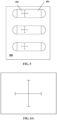
- FIG. 5 is another schematic diagram illustrating a sample plate 500 according to some embodiments of the present disclosure.
- a sample plate 500 may include a plurality of sample cells 501.
- a cross-shaped scaling pattern 502 may be arranged at the bottom of each of the sample cells 501.
- the scaling pattern 502 may include two line segments perpendicular to each other, and lengths of the two line segments may be the same or different.
- the magnification of the microscopic device may also be determined from the digital image generated by the image sensor 101.
- the magnification of the microscopic device may be determined based on the above formulas (1)-(2) and the length of any one of the two line segments in the scaling pattern 502.
- two magnifications may be determined respectively based on each of the two line segments, and then an average value of the two magnifications may be designated as the magnification of the microscopic device.
- the scaling pattern 502 on the sample plate 500 of FIG. 5 may also be used for identifying and correcting a distortion of the microscopic device 100.
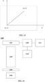
- an image of the scaling pattern 502 should also be two line segments perpendicular to each other, as shown in FIG. 6A .
- the processor 103 may recognize the distortion of the optical imaging device of the microscope device 100.
- the processor 103 may also correct the digital image generated by the image sensor 101 based on known parameters such as a size of the scaling pattern 502, to improve the image quality.
- sample plate according to the present disclosure and how to obtain the magnification of the microscopic device based on the scaling pattern on the sample plate are described above. It should be understood that the present disclosure may not be limited to the above embodiments.
- FIG. 7 is another schematic diagram illustrating a sample plate 700 according to some embodiments of the present disclosure.
- the sample plate 700 may include a plurality of sample cells 701 extending in a horizontal direction, and a scaling pattern 702 may be arranged at the bottom of each of the sample cells 701.
- the scaling pattern 702 may include a plurality of tick marks, each of the plurality of tick marks may extend in a horizontal direction (a first direction), and the plurality of tick marks may be arranged in the direction of a dotted line 703 (a second direction).
- the direction of the dotted line 703 is not a vertical direction perpendicular to the horizontal direction. In this way, the scaling pattern 702 may cover most of the area of the plurality of sample cells 701.
- magnification of the microscopic device 100 is large and the visual field may cover only a portion of the plurality of sample cells 701, this form of the scaling pattern 702 may ensure that at least one complete tick mark appears in the visual field. In this way, the magnification of the microscopic device may be accurately determined no matter where the sample is observed in the plurality of sample cells 701.
- the orientation of the sample plate and the plurality of sample cells may also be determined according to the scaling pattern on the sample plate.
- the sample plate 300 shown in FIG. 3 may include a plurality of sample cells 301 arranged in a vertical direction, and each sample cell 301 may extend in a horizontal direction.
- each tick mark in the scaling pattern 302 may extend in the horizontal direction, that is, an extension direction of a tick mark may be the same as the arrangement direction of the sample cell, and the arrangement directions of the plurality of tick marks may be the same as the arrangement directions of the plurality of sample cells.
- the processor 103 or the operator may determine the extension directions and arrangement directions of the plurality of sample cells based on the extension directions and arrangement directions of the plurality of the tick marks, and move the sample plate 300 on the sample table 105 based on the determined extension directions and arrangement directions of the plurality of sample cells.
- FIG. 8 is another schematic diagram illustrating a sample plate 800 according to some embodiments of the present disclosure.
- the sample plate 800 may include a plurality of sample cells 801 extending in the horizontal direction, and the plurality of sample cells 801 may be arranged in the vertical direction.
- a scaling pattern 802 may be arranged at the bottom of each of the plurality of sample cells 801.
- the scaling pattern 802 may include a first mark for determining an arrangement direction and an extension direction of a sample cell 801.
- the first mark may be composed of two arrows 803 and 804 perpendicular to each other, wherein the arrow 803 may extend in the vertical direction and the arrow 804 may extend in the horizontal direction.
- the longer arrow may indicate the arrangement direction of the sample cell
- the shorter arrow may indicate the extension direction of the sample cell.
- a length of the arrow 803 may be greater than a length of the arrow 804. Therefore, a plurality of sample cells 801 being arranged in the vertical direction may be determined based on the extension direction of the arrow 803, and the sample cell 802 extending in the horizontal direction may be determined based on the extension direction of the arrow 804.
- FIG. 9 is another schematic diagram illustrating a sample plate 900 according to some embodiments of the present disclosure.
- the sample plate 900 may include a plurality of sample cells 901 arranged in the horizontal direction, and each of the plurality of sample cells 901 may extend in the horizontal direction.
- a scaling pattern 902 may be arranged at the bottom of each sample cell 901.
- the scaling pattern 902 may include a first mark for determining an arrangement direction and an extension direction of a sample cell 901.
- the first mark may be composed of arrows 903 and 904, wherein the longer arrow 903 may indicate the arrangement direction of the sample cell 901, and the shorter arrow 904 may indicate the extension direction of the sample cell 901.
- the plurality of sample cells 901 arranged in the horizontal direction may be determined, and each sample cell 901 extending in the horizontal direction may also be determined.
- FIG. 10 is another schematic diagram illustrating a sample plate 1000 according to some embodiments of the present disclosure.
- the sample plate 1000 may include a plurality of sample cells 1001 arranged in a vertical direction, and each of the plurality of the sample cells 1001 may extend in the horizontal direction.
- a scaling pattern 1002 may be arranged at the bottom of a sample cell 1001.
- the scaling pattern 1002 includes a second mark 1004 for identifying the sample plate and a third mark 1003 for identifying the sample cell.
- the second mark 1004 and the third mark 1003 may be composed of a plurality of tick marks, which may be arranged in the horizontal direction, and each of the plurality of the tick marks may extend in the vertical direction.
- the leftmost tick mark 1005 and the rightmost tick mark 1006 may represent a beginning and an end of the second mark 1004 and the third identification 1003.
- the second mark 1004 and the third mark 1003 may be between the tick mark 1005 and the tick mark 1006.
- a serial number of the sample plate and a serial number of the sample cell may be determined respectively based on the second mark 1004 and the third mark 1003.
- the third mark 1003 includes two tick marks, and the serial number of the sample cell where the third mark 1003 is located is determined as 11.
- the third mark 1003 includes a tick mark, and based on spacing between the tick marks, a tick mark is missed in front of this tick mark. Therefore, the serial number of the sample cell where the third mark 1003 is located may be determined as 01.
- the serial number of the sample cell may be determined as 10.
- a missing tick mark may represent 0, and then the serial number of the sample plate 1000 may be determined as 1101.
- 0 and 1 may be represented by tick marks of different lengths. The longer tick mark may represent 1 and the shorter tick mark may represent 0.
- the set of tick marks in FIG. 11 may be determined as 1011.
- FIG. 12 is a flowchart illustrating a process for operating the microscopic device 100 according to some embodiments of the present disclosure.
- the sample plate may be placed on the sample table 105 (operation 1201). Samples to be observed and captured may be located in the sample cells of the sample plate.
- a digital image of the samples is generated by the image sensor 101 (operation 1202).
- the optical image generated by the optical imaging device 104 of the microscopic device 100 is received by the image sensor 101 and the digital image is generated.
- the digital image may be stored in the memory 102.
- the processor 103 may read the digital image from the memory 102 and perform various processes (operation 1203). For example, as described above, based on the scaling pattern in the digital image, the magnification of the microscopic device 100 may be determined; the extension direction and arrangement direction of the sample cell may be determined; the (number of) sample plate may be determined; or the (number of) sample cell may be determined, or the like.
- FIG. 14 is another schematic diagram illustrating a microscopic device according to some embodiments of the present disclosure.
- a microscopic device 1400 may be an optical microscopic device, including an image sensor 1401, a memory 1402, a transmission device 1411, an inputting device 1410, an optical imaging device 1404, a sample table 1405, and a light source 1406.
- the image sensor 1401, the optical imaging device 1404, the sample table 1405, and the light source 1406 may be similar to the corresponding devices in the microscopic device 100 shown in FIG. 1 , so a detailed description may not be repeated herein.
- the sample plate with the scaling pattern may be arranged on the sample table 1405, and the optical imaging device 1404 generates an optical image of samples.
- the scaling pattern in the sample plate is also be included in the optical image.
- the scaling pattern is configured to determine the magnification of the microscopic device, determine the direction of the sample plate, identify the sample plate or sample cell, or the like.
- the image sensor 1401 converts an optical image into a digital image.
- a user of the microscope device 1400 may input information about the scaling pattern (i.e., pattern information) by the inputting device 1410.
- the pattern information includes size information of the scaling pattern.
- the pattern information may include information about the length L of the line segment.
- the pattern information may include the information of the spacing D of the tick mark.
- the pattern information may include an identifier of the scaling pattern.
- the user may input a unique serial number of the scaling pattern by the inputting device 1410.
- the serial number of the scaling pattern may be stored in a database in association with relevant information of the scaling pattern. Based on the serial number, the scaling pattern corresponding to the serial number and the relevant information of the scaling pattern, such as size, spacing, etc., may be found in the database.
- a type of the sample plate may also be determined by the unique serial number of the scaling pattern.
- the serial number of the scaling pattern may also be stored in association with relevant parameters of the sample plate.
- the relevant parameters of the sample plate may include: the type of the sample plate, the numbers of sample cells, the depth of sample cells, or the like.
- the user may also input information about the sample (first sample information) by the inputting device 1410.
- the information may include the type of sample.
- the type of the samples such as red blood cells, yeast, algae, etc., may be determined.
- the transmission device 1411 may transmit the digital image to other devices.
- the transmission device 1411 may transmit the digital image to a remote server, such as a cloud server or the like.
- the server may include an image processing device to further process the received image.
- FIG. 19 is another schematic diagram illustrating a microscopic device according to some embodiments of the present disclosure.
- the microscopic device 1900 may include an image sensor 1901, a memory 1902, a transmission device 1911, an inputting device 1910, an optical imaging device 1904, a sample table 1905, and a light source 1906. These components are similar to the corresponding components of the microscopic device 1400 shown in FIG. 14 , and may not be repeated herein.
- the microscopic device 1900 may also include a controller 1912 and a receiving device 1913.
- the receiving device 1913 may receive information transmitted by external devices, and the controller 1912 may control the operation of the microscopic device 1900 based on the information.
- the user may interact with the microscopic device 1900 by a mobile device (e.g., a mobile phone, tablet, laptop, etc.).
- the microscopic device 1900 may transmit a captured microscopic image to the mobile device and display the microscopic image on the mobile device.
- the user may adjust a photographing parameter (such as magnification, observation area, etc.) of the microscopic device 1900 based on a captured microscopic image, and transmit the photographing parameter to the microscopic device 1900 by the mobile device.
- the microscopic device 1900 may adjust based on the photographing parameter included in the information transmitted by the mobile device, re-capture the microscopic image, and transmit the new microscopic image to the mobile device.
- an interaction between the microscopic device 1900 and the mobile device may be carried out directly or indirectly through, for example, a cloud server, which may not be limited by the present disclosure.
- FIG. 15 is a schematic diagram illustrating an image processing device according to some embodiments of the present disclosure.
- an image processing device 1500 may include a receiving device 1501, a storage device 1502, a processor 1503, and a transmission device 1504.
- the receiving device 1501 receives a digital image captured by the above-mentioned microscopic device according to the present disclosure.
- a scaling pattern is included in the digital image.
- the receiving device 1501 may also receive pattern information and/or first sample information related to the digital image.
- the storage device 1502 stores the digital image and various information received by the receiving device 1501.
- the processor 1503 obtains the digital image and various information from the storage device 1502 and process the digital image.
- the processor 1503 determines the magnification of the microscopic device based on the scaling pattern in the digital image.
- the transmission device 1504 may transmit the digital image and information related to the digital image (e.g., the magnification, etc.) to, for example, a mobile device or the like.
- information related to the digital image e.g., the magnification, etc.
- the processor 1503 may also need to further combine the pattern information related to the digital image to determine the magnification of the microscopic device.
- the processor 1503 may also determine the direction of the sample plate where the sample is located based on the pattern information. For example, when the sample plate is the sample plate 900 shown in FIG. 9 , the pattern information may indicate that the direction of the arrow is the same as the longitudinal direction of the sample plate 900. In this way, the processor 1503 may recognize the direction of the arrow of the scaling pattern from the digital image, and designate the direction of the arrow as the longitudinal direction of the sample plate.
- the processor 1503 may classify digital images based on pattern information. For example, the digital images may be classified based on the size of the scaling pattern, and digital images with the same size of the scaling pattern may be divided into a group. When browsing the group of digital images later, the digital images may be scaled to make the size of the scaling pattern the same, so that users may intuitively observe and compare the relative size of the samples in each digital image.
- the processor 1503 may generate a first image from the pattern information and integrate the first image into the digital image. For example, as shown in FIG. 16 , for the sample plate shown in FIG. 2 , the processor 1503 may obtain that the length L of the tick mark is 5 ⁇ m based on the pattern information. The processor 1503 may generate a message with the word "5 ⁇ m," and the first image may be integrated into the digital image. In the synthesized digital image, the value of the length L of the tick mark may be marked near the tick mark, so that the user may more intuitively understand the size of the sample when browsing the digital image.
- the processor 1503 may classify the digital images based on the first sample information. For example, when the first sample information includes the type of the samples, the processor 1503 may determine that the digital images of samples of the same type belong to the same group.
- the first sample information may also include other information such as production date, photographing date, source, copyright information, or the like.
- the processor 1503 may also divide the digital images with the same date into a group.
- the processor 1503 may generate a second image based on the first sample information and integrate the second image into the digital image. As shown in FIG. 17 , when the first sample information indicates that the type of the samples is human breast cancer cells (MCF-7 cells), the processor 1503 may generate a second image 1701 including the word "MCF-7 cells" and integrate the image 1701 into the digital image. In this way, when the digital image is displayed on a display, for example, the type of the sample may be directly known.
- MCF-7 cells human breast cancer cells
- a client may find and download the digital image from the server.
- the client may enter a keyword, such as yeast cells, and the keyword may be transmitted to a remote server.
- the server may find digital images of yeast cells in all sample information in the database based on the keyword, and provide a list or thumbnails of these digital images to the client.
- the client may select and download a selected digital image and related information of the selected digital image based on the information provided by the server.
- the client may pay a fee to the server to obtain a license to use the selected digital image. After the server determines that the client has obtained the license, the selected digital image may be transmitted to the client.
- the processor 1503 may analyze the digital image based on the scaling pattern to obtain second sample information related to the sample.
- the second sample information may include, for example, diameters of the samples, values of major axis and values of minor axis of the samples, a size of the visual field, a concentration of the samples and other information.
- FIG. 18 is another schematic diagram illustrating a microscopic image according to some embodiments of the present disclosure.
- the processor 1503 may determine that the length unit of the scaling pattern in the digital image is 5 ⁇ m. Based on a determination that the length unit of the scaling pattern in the digital image is 5 ⁇ m, the magnification of the digital image in FIG. 18 may be determined as 9.8.
- the processor 1503 may further determine that the type of sample in the digital image is yeast cells. Based on the information that the type of sample in the digital image is yeast cells, the processor 1503 may perform an image recognition operation on identifying yeast cells. For example, the processor 1503 may determine a yeast cell 1802 based on the image recognition operation and determine that the diameter of the yeast cell 1802 is 6 ⁇ m based on the scaling pattern, the diameter of the yeast cell 1802 may be stored in the second sample information.
- the processor 1503 may determine a plurality of yeast cells by the image recognition operation and determine the diameter of each of the plurality of the yeast cells based on the scaling pattern. Then, the processor 1503 may store an average value of the diameters of the plurality of yeast cells in the second sample information as a diameter of the plurality of yeast cells.
- the processor 1503 also determines the size of a visual field of photographing and the concentration of the samples from the digital image. As shown in FIG. 18 , the processor 1503 may determine that the area of the sample plate in the digital image is 0.46 ⁇ 0.35 mm 2 based on the scaling pattern. In addition, as described above, the type of sample plate may also be determined based on the scaling pattern, so that the depth of the sample cell may be obtained as 0.5 ⁇ m. In this way, the processor 1503 may determine that the concentration of yeast cells is about 5 ⁇ 10 6 /ml.
- the processor 1503 may determine the value of the major axis and the value of the minor axis of the sample from the digital image.
- FIG. 20 is another schematic diagram illustrating a microscopic image of chlorella according to some embodiments of the present disclosure.
- the processor 1503 may determine the value of the major axis and the value of the minor axis of each chlorella based on the scaling pattern in FIG. 20 , and further determine that the average value of the minor axis of the chlorella is about 17.66 ⁇ m, and the value of the major axis of the chlorella is about 19.11 ⁇ m.
- a microscopic analysis system including the microscopic device, the image processing device, the mobile device, etc.
- the image processing device of the present disclosure may be a single server or multiple servers, or a cloud server.
- the mobile device may control the microscopic device by the cloud server (for example, adjusting the photographing parameter, etc.), or receive the microscopic image captured by the microscopic device by the cloud server.
- the cloud server may transmit an update of an application to the microscopic device and/or the mobile device.
- a plurality of microscopic devices 1 ⁇ N may be connected to the cloud server at the same time.
- the mobile device may browse the image captured by a specified microscopic device or control the operation of the microscopic device as needed.
- the cloud server may store and analyze microscopic images captured by the plurality of microscopic devices, and may transmit the microscopic images and an analysis result to the mobile device.
- the microscopic device includes: an optical imaging device configured to obtain a sample on a sample plate to generate an optical image of the sample, wherein the optical image includes a scaling pattern for determining the magnification of the microscopic device; an image sensor configured to generate a digital image from the optical image; a transmission device configured to transmit the digital image; and a receiving device configured to receive information from the cloud server and the mobile device.
- the mobile device is configured to receive the digital image from the cloud server and the microscopic device; transmit a photographing parameter to the cloud server and the microscopic device; and transmit the digital image from the microscopic device to the cloud server.
- the cloud server is configured to receive the digital image from the microscopic device and the mobile device; receive the photographing parameter from the mobile device and forward the photographing parameter to the microscopic device; transmit the digital image from the microscopic device to the mobile device; and analyze the digital image and transmit an analysis result to the mobile device.
- exemplary means “serving as an example, instance, or illustration” rather than as a “model” to be exactly reproduced. Any implementation illustratively described herein is not necessarily to be construed as preferred or advantageous over other implementations. Furthermore, the present disclosure is not to be bound by any expressed or implied theory presented in the preceding technical field, background, summary, or detailed description.
- the term “substantially” is meant to encompass any minor variation due to design or manufacturing imperfections, tolerances of devices or elements, environmental influences, and/or other factors.
- the term “substantially” also allows for differences from a perfect or ideal situation due to parasitic effects, noise, and other practical considerations that may exist in an actual implementation.
- connection means that one element/node/feature is electrically, mechanically, logically, or otherwise directly connected to another element/node/feature (or direct communication).
- coupled means that one element/node/feature can be mechanically, electrically, logically, or otherwise linked, directly or indirectly, with another element/node/feature to Interactions are allowed, even though the two features may not be directly connected. That is, “coupled” is intended to encompass both direct and indirect coupling of elements or other features, including connections that utilize one or more intervening elements.
- the term “providing” is used in a broad sense to encompass all manners of obtaining an object, thus “providing something” includes, but is not limited to, “purchasing,” “preparing/manufacturing,” “arranging/setting,” “installing/ assembling,” and/or “ordering” the objects, etc.
Landscapes
- Engineering & Computer Science (AREA)
- Physics & Mathematics (AREA)
- Chemical & Material Sciences (AREA)
- General Physics & Mathematics (AREA)
- Health & Medical Sciences (AREA)
- General Health & Medical Sciences (AREA)
- Life Sciences & Earth Sciences (AREA)
- Multimedia (AREA)
- Analytical Chemistry (AREA)
- Pathology (AREA)
- Immunology (AREA)
- Signal Processing (AREA)
- Biochemistry (AREA)
- Dispersion Chemistry (AREA)
- Theoretical Computer Science (AREA)
- Molecular Biology (AREA)
- Biomedical Technology (AREA)
- Computer Vision & Pattern Recognition (AREA)
- Optics & Photonics (AREA)
- Microscoopes, Condenser (AREA)
Description
- The present disclosure relates to a microscopic device and an image processing device.
- At present, a sample plate for cell counting or analysis usually includes one or more sample cells. The sample cells are used to accommodate cell samples. The count, concentration, size, and other parameters of cell samples are obtained through a microscopic imaging system and an image analysis system. However, the detection of these parameters depends on the observation ability of the microscope or the microscopic imaging system. The most fundamental and important feature parameter is the magnification, and the actual magnification of many microscopic devices on the market is inconsistent with their nominal value.
- At present, the calibration of the magnification of the microscope mainly adopts a micrometer technique or other similar techniques, and the actual magnification of the microscope is calibrated based on the cooperation of an eyepiece micrometer and an objective micrometer. For example, the actual magnification of the microscope is determined by comparing a known size of the spacing in a scale with a size obtained in the microscopic imaging system. However, these technologies have certain defects. When the eyepiece or objective is replaced, the actual magnification of the microscope needs to be recalibrated, and at this time, the cell samples need to be removed, which leads to the repetition and trouble of the operation. The original visual field for observation needs to be searched again, which may lead to a movement of the cell samples in the sample cell and affect an observation result.
- Therefore, it is very significant to measure the magnification of the microscope or microscopic imaging system. However, the existing cell counting plates do not allow accurate calibration of the magnification of the microscope, resulting in the inconsistency between the detected parameters and the actual parameters, and affection of the accuracy of the final result.
-
US 2018/130233 A1 discloses an embodiment of a calibration element for an analytical microscope that comprises a substantially non-periodic pattern of features that exhibit contrast when illuminated by a light beam. - The invention is set out in the appended set of claims.
- Other features of the present disclosure and advantages thereof may become apparent from the following detailed description of embodiments of the present disclosure with reference to the drawings.
- The drawings forming a portion of the present disclosure describe embodiments of the present disclosure and are used together with the present disclosure to explain the principles of the present disclosure.
- Referring to the drawings, the present disclosure may be more clearly understood according to the following detailed description, wherein:
-
FIG. 1 is a schematic diagram illustrating a microscopic device according to some embodiments of the present disclosure; -
FIG. 2 is a schematic diagram illustrating a sample plate according to some embodiments of the present disclosure; -
FIG. 3 is another schematic diagram illustrating a sample plate according to some embodiments of the present disclosure; -
FIG. 4 is another schematic diagram illustrating a sample plate according to some embodiments of the present disclosure; -
FIG. 5 is another schematic diagram illustrating a sample plate according to some embodiments of the present disclosure; -
FIG. 6A is a schematic diagram illustrating a scaling pattern on a sample plate according to some embodiments of the present disclosure; -
FIG. 6B is a schematic diagram illustrating an image of the scaling pattern on a sample plate according to some embodiments of the present disclosure; -
FIG. 7 is another schematic diagram illustrating a sample plate according to some embodiments of the present disclosure; -
FIG. 8 is another schematic diagram illustrating a sample plate according to some embodiments of the present disclosure; -
FIG. 9 is another schematic diagram illustrating a sample plate according to some embodiments of the present disclosure; -
FIG. 10 is another schematic diagram illustrating a sample plate according to some embodiments of the present disclosure; -
FIG. 11 is a schematic diagram illustrating a set of tick marks of the scaling pattern on the sample plate according to some embodiments of the present disclosure; -
FIG. 12 is a flowchart illustrating a process for operating the microscopic device according to some embodiments of the present disclosure; -
FIG. 13 is a schematic diagram illustrating an arrangement direction of pixels of an image sensor according to some embodiments of the present disclosure; -
FIG. 14 is another schematic diagram illustrating a microscopic device according to some embodiments of the present disclosure; -
FIG. 15 is a schematic diagram illustrating an image processing device according to some embodiments of the present disclosure; -
FIG. 16 is a schematic diagram illustrating a microscopic image according to some embodiments of the present disclosure; -
FIG. 17 is another schematic diagram illustrating a microscopic image according to some embodiments of the present disclosure; -
FIG. 18 is another schematic diagram illustrating a microscopic image according to some embodiments of the present disclosure; -
FIG. 19 is another schematic diagram illustrating a microscopic device according to some embodiments of the present disclosure; -
FIG. 20 is another schematic diagram illustrating a microscopic image according to some embodiments of the present disclosure; and -
FIG. 21 is a schematic diagram illustrating a microscopic analysis system according to some embodiments of the present disclosure. - It should be noted that in some embodiments described below, the same number is used between different drawings to indicate the same part or a part with the same function, and the repeated description thereof is omitted. In the present disclosure, similar labels and letters are used to indicate similar items. Therefore, once an item is defined in a drawing, a further discussion may not need to be described in subsequent drawings.
- In order to facilitate understanding, position, size, range of each structure shown in the drawings or the like may not indicate the actual position, size, or range in some cases. Therefore, the present disclosure is not limited to the position, dimension, ranges disclosed in the drawings, or the like.
- The embodiments of the present disclosure are described in detail with reference to the drawings. It should be noted that unless stated otherwise or obvious from the context, the relative arrangement of components and steps, numerical expressions, and values set forth in these embodiments do not limit the scope of the present disclosure.
- The following description of at least one embodiment is merely illustrative in nature and is in no way intended to limit the present disclosure and its application or use.
- The techniques, methods, and devices known to those of ordinary skill in the art may not be discussed in detail, but where appropriate, such techniques, methods, and devices should be considered as a part of the present disclosure.
- In all the examples shown and discussed in the present disclosure, any specific value should be interpreted as merely for example, and not as a limitation. Therefore, other examples of the embodiments may have different values.
-
FIG. 1 is a schematic diagram illustrating a microscopic device according to some embodiments of the present disclosure. - As shown in
FIG. 1 , themicroscopic device 100 includes animage sensor 101, amemory 102, aprocessor 103, anoptical imaging device 104, a sample table 105, and alight source 106. During an operation, a sample plate is arranged on the sample table 105. Thelight source 106 may emit light towards the sample plate. Theoptical imaging device 104 may include, for example, an objective and an eyepiece (not shown). Each of the objective and the eyepiece may be composed of one or more sets of lenses. An optical image generated by theoptical device 104 is received by theimage sensor 101 and converted into a digital image by theimage sensor 101. The image sensor may be, for example, a charge-coupled device (CCD), a complementary metal-oxide semiconductor (CMOS), or the like. In some embodiments according to the present disclosure, an image capturing device such as a mobile phone, or a camera may also be arranged in an optical path. The image capturing device may also include image sensors, and may capture an image of a sample in the sample plate through theoptical device 104. - The digital image captured by the
image sensor 101 may be stored in thememory 102, and theprocessor 103 may read and process the digital image in thememory 102. -
FIG. 2 is a schematic diagram illustrating a sample plate according to some embodiments of the present disclosure. As shown inFIG. 2 , asample plate 200 may include a plurality ofsample cells 201 in which samples may be accommodated. In addition, thesample plate 200 also includes ascaling pattern 202. - In the embodiments shown in
FIG. 2 , thescaling pattern 202 is located at the bottom of a sample cell (i.e., on the surface where the sample cell contacts the sample). When capturing an image of a sample by themicroscope device 100, theoptical imaging device 104 may focus on the bottom of the sample cell, and set thescaling pattern 202 at the bottom of the sample cell to capture a clear image of the scaling pattern while capturing the sample image. Thescaling pattern 202 may be a line segment along a horizontal direction with a length of L. For example, in some embodiments, L may be 1 µm-100 µm. Using thescaling pattern 202, the magnification of themicroscopic device 100 may be accurately obtained. - For example, as shown in
FIG. 13 , for theimage sensor 101 whose pixels are evenly arranged in two directions perpendicular to each other (the X direction and the Y direction), if coordinates at both ends of the line segment of thescaling pattern 202 are (x1, y1) and (x2, y2) in the digital image generated by theimage sensor 101, respectively. Then, the coordinates (x1, y1) and (x2, y2) represent positions of the pixels corresponding to both ends of the line segment on theimage sensor 101. Then, a size k of an image of the line segment generated by the line segment on the sample plate on theimage sensor 101 may be determined based on a formula (1):
image sensor 101, that is, a distance from a center of a pixel to a center of an adjacent pixel of the pixel along the X direction or Y direction. The function "sqrt" represents determining a square root. - Then, a magnification M of the
optical imaging device 104 of themicroscope device 100 may be determined based on the following formula (2):
- In the above method, an actual magnification of the
microscopic device 100 may be accurately obtained. - In the above embodiment, a pixel array of the
image sensor 101 may be a rectangular array, and the spacing of the adjacent pixels may be the same in the X direction and the Y direction. In other embodiments according to the present disclosure, the spacing between the adjacent pixels of theimage sensor 101 may be different in the X direction and the Y direction. For example, if the spacing between the adjacent pixels along the X direction is D1 and the spacing between adjacent pixels along the Y direction is D2, the size k of the image of the line segment generated by the line segment on the sample plate on theimage sensor 101 may be determined based on the following formula (3):
- Then, the actual magnification M of the
microscopic device 100 may be accurately obtained. - The above operation of determining the actual magnification is performed by the
processor 103 of themicroscope device 100. For example, the spacing between adjacent pixels of theimage sensor 101 may be stored in thememory 102 in advance. When theimage sensor 101 generates a digital image of thesample plate 200, the digital image may be stored in thememory 102. - Then, the
processor 103 may read the digital image from thememory 102 and recognize the scaling pattern in the digital image. Next, theprocessor 103 may read the spacing between adjacent pixels of theimage sensor 101 from the memory and determine the actual magnification M of themicroscopic device 101 based on the above formulas (1)-(3). - In addition, in some embodiments according to the present disclosure, for the
sample plate 200 with a plurality ofsample cells 201, the magnification M may also be determined using the following method. - For the
sample plate 200 shown inFIG. 2 with threesample cells 201, the corresponding magnifications M1, M2, and M3 may be determined respectively based on thescaling pattern 202 on each of thesample cells 201, and then the actual magnification M of the microscopic device may be calculated by a formula (4):
- That is, an average value of the magnifications M1, M2, and M3 are designated as the actual magnification M of the microscopic device. In this way, the calculation error may be reduced and the accuracy of magnification may be further improved.
- In addition, in other embodiments according to the present disclosure, a sum K' of the line segments of each
scaling pattern 202 may be determined based on the following formula (5):
first sample cell 202 in the upper ofFIG. 2 in the digital image; (x3, y3) and (x4, y4) are the coordinates of both ends of the line segment of the scaling pattern of asecond sample cell 202 in the upper ofFIG. 2 in the digital image, (x5, y5) and (x6, y6) are the coordinates of both ends of the line segment of the scaling pattern of athird sample cell 202 in the lower ofFig. 2 in the digital image. - Then, the actual magnification M of the microscopic device may be determined based on a formula (6):

- In this way, the calculation error may be reduced and the accuracy of magnification may be further improved.
- The above embodiments briefly describe how to determine the actual magnification of the
microscopic device 100 based on the scaling pattern on the sample plate. It should be understood that the present disclosure is not limited to the above methods. Under the instruction and enlightenment of the present disclosure, those skilled in the art may also adopt other ways to determine the actual magnification of themicroscopic device 100 based on the scaling pattern. -
FIG. 3 is another schematic diagram illustrating an sample plate according to some embodiments of the present disclosure. As shown inFIG. 3 , asample plate 300 may include a plurality ofsample cells 301 in which samples to be observed and captured may be accommodated. In addition, thesample plate 300 also has ascaling pattern 302. - In the embodiments shown in
FIG. 3 , thescaling pattern 302 may be located at the bottom of the sample cell. Thescaling pattern 302 may be tick marks arranged at an equal interval, each tick mark may extend along the horizontal direction (a first direction), and spacing of the tick marks in the vertical direction (a second direction) is D. In some embodiments according to the present disclosure, the spacing D may be, for example, 1 µm -10 µm. The magnification of the microscopic device may be accurately determined based on thescaling pattern 302. - For example, based on the digital image generated by the
image sensor 101, theprocessor 103 may obtain a coordinate (x1', y1') of a point on a tick mark in thescaling pattern 302 and a coordinate (x2', y2') of an intersection point of a line along the direction vertical to the tick mark and passing through point (x1', y1') and an adjacent tick mark. - Using a method similar to the method described above, the actual magnification of the
microscopic device 100 may be determined. - In the example shown in
FIG. 3 , a plurality oftick marks 302 may be arranged on each sample cell. When the magnification of themicroscopic device 100 is relatively large, the actual magnification may be accurately determined even if only a portion of a sample cell is included in the visual field. -
FIG. 4 is another schematic diagram illustrating asample plate 400 according to some embodiments of the present disclosure. As shown inFIG. 4 , in thesample plate 400, thescaling pattern 402 may be arranged outside asample cell 401. In this way, interference of thescaling pattern 402 on the sample in thesample cell 401 may be avoided, and a sample may be more clearly observed and analyzed. In order to capture a clear image of thescaling pattern 402, thescaling pattern 402 may be located on the same plane as the bottom of the sample cell. -
FIG. 5 is another schematic diagram illustrating asample plate 500 according to some embodiments of the present disclosure. As shown inFIG. 5 , asample plate 500 may include a plurality ofsample cells 501. Across-shaped scaling pattern 502 may be arranged at the bottom of each of thesample cells 501. Thescaling pattern 502 may include two line segments perpendicular to each other, and lengths of the two line segments may be the same or different. - Using the
scaling pattern 502 on thesample plate 500 ofFIG. 5 , the magnification of the microscopic device may also be determined from the digital image generated by theimage sensor 101. For example, the magnification of the microscopic device may be determined based on the above formulas (1)-(2) and the length of any one of the two line segments in thescaling pattern 502. Alternatively, two magnifications may be determined respectively based on each of the two line segments, and then an average value of the two magnifications may be designated as the magnification of the microscopic device. - In addition, the
scaling pattern 502 on thesample plate 500 ofFIG. 5 may also be used for identifying and correcting a distortion of themicroscopic device 100. For example, when there is no distortion in theoptical imaging device 104 of themicroscope device 100, an image of thescaling pattern 502 should also be two line segments perpendicular to each other, as shown inFIG. 6A . However, if there is a distortion in theoptical imaging device 104 of themicroscope device 100, the two line segments in the image of thescaling pattern 502 may no longer be vertical, as shown inFIG. 6B . Based on the image of the two line segments, theprocessor 103 may recognize the distortion of the optical imaging device of themicroscope device 100. Further, theprocessor 103 may also correct the digital image generated by theimage sensor 101 based on known parameters such as a size of thescaling pattern 502, to improve the image quality. - The sample plate according to the present disclosure and how to obtain the magnification of the microscopic device based on the scaling pattern on the sample plate are described above. It should be understood that the present disclosure may not be limited to the above embodiments.
- For example,
FIG. 7 is another schematic diagram illustrating asample plate 700 according to some embodiments of the present disclosure. As shown inFIG. 7 , thesample plate 700 may include a plurality ofsample cells 701 extending in a horizontal direction, and ascaling pattern 702 may be arranged at the bottom of each of thesample cells 701. Thescaling pattern 702 may include a plurality of tick marks, each of the plurality of tick marks may extend in a horizontal direction (a first direction), and the plurality of tick marks may be arranged in the direction of a dotted line 703 (a second direction). The direction of the dottedline 703 is not a vertical direction perpendicular to the horizontal direction. In this way, thescaling pattern 702 may cover most of the area of the plurality ofsample cells 701. When the magnification of themicroscopic device 100 is large and the visual field may cover only a portion of the plurality ofsample cells 701, this form of thescaling pattern 702 may ensure that at least one complete tick mark appears in the visual field. In this way, the magnification of the microscopic device may be accurately determined no matter where the sample is observed in the plurality ofsample cells 701. - In addition, in some embodiments according to the present disclosure, the orientation of the sample plate and the plurality of sample cells may also be determined according to the scaling pattern on the sample plate. For example, the
sample plate 300 shown inFIG. 3 may include a plurality ofsample cells 301 arranged in a vertical direction, and eachsample cell 301 may extend in a horizontal direction. - When observing and photographing samples in the plurality of
sample cells 301 through themicroscope device 100, it may be impossible to observe and photograph all the samples in the plurality ofsample cells 301 at the same time due to the visual field and other reasons. Therefore, it is necessary to move the sample table 105 so that the sample plate is moved in the visual field, to observe and photographdifferent sample cells 301 on thesample plate 300 or different portions of thesame sample cell 301. - As shown in
FIG. 3 , each tick mark in thescaling pattern 302 may extend in the horizontal direction, that is, an extension direction of a tick mark may be the same as the arrangement direction of the sample cell, and the arrangement directions of the plurality of tick marks may be the same as the arrangement directions of the plurality of sample cells. Therefore, although only a portion of the plurality of sample cells may be displayed in the visual field or the image captured by the microscopic device, to perform an operation of observing and photographingdifferent sample cells 301 or different areas of thesame sample cell 301, theprocessor 103 or the operator may determine the extension directions and arrangement directions of the plurality of sample cells based on the extension directions and arrangement directions of the plurality of the tick marks, and move thesample plate 300 on the sample table 105 based on the determined extension directions and arrangement directions of the plurality of sample cells. -
FIG. 8 is another schematic diagram illustrating asample plate 800 according to some embodiments of the present disclosure. As shown inFIG. 8 , thesample plate 800 may include a plurality ofsample cells 801 extending in the horizontal direction, and the plurality ofsample cells 801 may be arranged in the vertical direction. Ascaling pattern 802 may be arranged at the bottom of each of the plurality ofsample cells 801. Thescaling pattern 802 may include a first mark for determining an arrangement direction and an extension direction of asample cell 801. The first mark may be composed of twoarrows arrow 803 may extend in the vertical direction and thearrow 804 may extend in the horizontal direction. In addition, in the example, the longer arrow may indicate the arrangement direction of the sample cell, and the shorter arrow may indicate the extension direction of the sample cell. As shown inFIG. 8 , a length of thearrow 803 may be greater than a length of thearrow 804. Therefore, a plurality ofsample cells 801 being arranged in the vertical direction may be determined based on the extension direction of thearrow 803, and thesample cell 802 extending in the horizontal direction may be determined based on the extension direction of thearrow 804. -
FIG. 9 is another schematic diagram illustrating asample plate 900 according to some embodiments of the present disclosure. As shown inFig. 9 , thesample plate 900 may include a plurality ofsample cells 901 arranged in the horizontal direction, and each of the plurality ofsample cells 901 may extend in the horizontal direction. Ascaling pattern 902 may be arranged at the bottom of eachsample cell 901. Thescaling pattern 902 may include a first mark for determining an arrangement direction and an extension direction of asample cell 901. The first mark may be composed ofarrows longer arrow 903 may indicate the arrangement direction of thesample cell 901, and theshorter arrow 904 may indicate the extension direction of thesample cell 901. In this way, through the extension direction ofarrows sample cells 901 arranged in the horizontal direction may be determined, and eachsample cell 901 extending in the horizontal direction may also be determined. -
FIG. 10 is another schematic diagram illustrating asample plate 1000 according to some embodiments of the present disclosure. As shown inFIG. 10 , thesample plate 1000 may include a plurality ofsample cells 1001 arranged in a vertical direction, and each of the plurality of thesample cells 1001 may extend in the horizontal direction. Ascaling pattern 1002 may be arranged at the bottom of asample cell 1001. Thescaling pattern 1002 includes asecond mark 1004 for identifying the sample plate and athird mark 1003 for identifying the sample cell. Thesecond mark 1004 and thethird mark 1003 may be composed of a plurality of tick marks, which may be arranged in the horizontal direction, and each of the plurality of the tick marks may extend in the vertical direction. Theleftmost tick mark 1005 and therightmost tick mark 1006 may represent a beginning and an end of thesecond mark 1004 and thethird identification 1003. Thesecond mark 1004 and thethird mark 1003 may be between thetick mark 1005 and thetick mark 1006. A serial number of the sample plate and a serial number of the sample cell may be determined respectively based on thesecond mark 1004 and thethird mark 1003. - As shown in
FIG. 10 , in thelower sample cell 1001, thethird mark 1003 includes two tick marks, and the serial number of the sample cell where thethird mark 1003 is located is determined as 11. In theupper sample cell 1001, thethird mark 1003 includes a tick mark, and based on spacing between the tick marks, a tick mark is missed in front of this tick mark. Therefore, the serial number of the sample cell where thethird mark 1003 is located may be determined as 01. Similarly, for thethird mark 1003 in themiddle sample cell 1001, the serial number of the sample cell may be determined as 10. - Similarly, in the
second mark 1004, based on the spacing between the tick marks, a missing tick mark may represent 0, and then the serial number of thesample plate 1000 may be determined as 1101. - In addition, in some embodiments of the present disclosure, other ways may also be used to represent a
number FIG. 11 , 0 and 1 may be represented by tick marks of different lengths. The longer tick mark may represent 1 and the shorter tick mark may represent 0. The set of tick marks inFIG. 11 may be determined as 1011. - It should be understood that under the instruction and enlightenment of the present disclosure, those skilled in the art may combine the first mark, the second mark, the third mark, and the tick mark in other ways as a scaling pattern.
-
FIG. 12 is a flowchart illustrating a process for operating themicroscopic device 100 according to some embodiments of the present disclosure. - As shown in
FIG. 12 , the sample plate may be placed on the sample table 105 (operation 1201). Samples to be observed and captured may be located in the sample cells of the sample plate. - Then, a digital image of the samples is generated by the image sensor 101 (operation 1202). The optical image generated by the
optical imaging device 104 of themicroscopic device 100 is received by theimage sensor 101 and the digital image is generated. The digital image may be stored in thememory 102. - Then, the
processor 103 may read the digital image from thememory 102 and perform various processes (operation 1203). For example, as described above, based on the scaling pattern in the digital image, the magnification of themicroscopic device 100 may be determined; the extension direction and arrangement direction of the sample cell may be determined; the (number of) sample plate may be determined; or the (number of) sample cell may be determined, or the like. -
FIG. 14 is another schematic diagram illustrating a microscopic device according to some embodiments of the present disclosure. As shown inFIG. 14 , amicroscopic device 1400 may be an optical microscopic device, including animage sensor 1401, amemory 1402, atransmission device 1411, aninputting device 1410, anoptical imaging device 1404, a sample table 1405, and alight source 1406. Theimage sensor 1401, theoptical imaging device 1404, the sample table 1405, and thelight source 1406 may be similar to the corresponding devices in themicroscopic device 100 shown inFIG. 1 , so a detailed description may not be repeated herein. - The sample plate with the scaling pattern may be arranged on the sample table 1405, and the
optical imaging device 1404 generates an optical image of samples. In addition, the scaling pattern in the sample plate isalso be included in the optical image. As described above, the scaling pattern is configured to determine the magnification of the microscopic device, determine the direction of the sample plate, identify the sample plate or sample cell, or the like. Theimage sensor 1401 converts an optical image into a digital image. - In addition, a user of the
microscope device 1400 may input information about the scaling pattern (i.e., pattern information) by theinputting device 1410. The pattern information includes size information of the scaling pattern. For example, when the scaling pattern is thescaling pattern 202 shown inFIG. 2 , the pattern information may include information about the length L of the line segment. When the scaling pattern is thescaling pattern 302 shown inFIG. 3 , the pattern information may include the information of the spacing D of the tick mark. - In addition, the pattern information may include an identifier of the scaling pattern. For example, the user may input a unique serial number of the scaling pattern by the
inputting device 1410. The serial number of the scaling pattern may be stored in a database in association with relevant information of the scaling pattern. Based on the serial number, the scaling pattern corresponding to the serial number and the relevant information of the scaling pattern, such as size, spacing, etc., may be found in the database. - In some illustrative embodiments, a type of the sample plate may also be determined by the unique serial number of the scaling pattern. For example, in the database, the serial number of the scaling pattern may also be stored in association with relevant parameters of the sample plate. For example, the relevant parameters of the sample plate may include: the type of the sample plate, the numbers of sample cells, the depth of sample cells, or the like.
- In addition, the user may also input information about the sample (first sample information) by the
inputting device 1410. For example, the information may include the type of sample. In this way, based on the information about the sample, the type of the samples such as red blood cells, yeast, algae, etc., may be determined. - The
transmission device 1411 may transmit the digital image to other devices. For example, thetransmission device 1411 may transmit the digital image to a remote server, such as a cloud server or the like. The server may include an image processing device to further process the received image. -
FIG. 19 is another schematic diagram illustrating a microscopic device according to some embodiments of the present disclosure. As shown inFIG. 19 , themicroscopic device 1900 may include animage sensor 1901, amemory 1902, atransmission device 1911, aninputting device 1910, anoptical imaging device 1904, a sample table 1905, and alight source 1906. These components are similar to the corresponding components of themicroscopic device 1400 shown inFIG. 14 , and may not be repeated herein. In addition, as shown inFIG. 19 , themicroscopic device 1900 may also include acontroller 1912 and areceiving device 1913. Thereceiving device 1913 may receive information transmitted by external devices, and thecontroller 1912 may control the operation of themicroscopic device 1900 based on the information. In some embodiments according to the present disclosure, the user may interact with themicroscopic device 1900 by a mobile device (e.g., a mobile phone, tablet, laptop, etc.). For example, themicroscopic device 1900 may transmit a captured microscopic image to the mobile device and display the microscopic image on the mobile device. The user may adjust a photographing parameter (such as magnification, observation area, etc.) of themicroscopic device 1900 based on a captured microscopic image, and transmit the photographing parameter to themicroscopic device 1900 by the mobile device. Then, themicroscopic device 1900 may adjust based on the photographing parameter included in the information transmitted by the mobile device, re-capture the microscopic image, and transmit the new microscopic image to the mobile device. - In addition, an interaction between the
microscopic device 1900 and the mobile device may be carried out directly or indirectly through, for example, a cloud server, which may not be limited by the present disclosure. -
FIG. 15 is a schematic diagram illustrating an image processing device according to some embodiments of the present disclosure. As shown inFIG. 15 , an image processing device 1500 may include areceiving device 1501, astorage device 1502, aprocessor 1503, and atransmission device 1504. - The
receiving device 1501 receives a digital image captured by the above-mentioned microscopic device according to the present disclosure. A scaling pattern is included in the digital image. - In addition, in some embodiments according to the present disclosure, the
receiving device 1501 may also receive pattern information and/or first sample information related to the digital image. - The
storage device 1502 stores the digital image and various information received by thereceiving device 1501. - The
processor 1503 obtains the digital image and various information from thestorage device 1502 and process the digital image. Theprocessor 1503 determines the magnification of the microscopic device based on the scaling pattern in the digital image. - The
transmission device 1504 may transmit the digital image and information related to the digital image (e.g., the magnification, etc.) to, for example, a mobile device or the like. - In some embodiments according to the present disclosure, since specifications of the sample plates may be different, the parameters such as the length and/or spacing of the tick marks of the scaling pattern on the sample plates with different specifications may be different. In this case, the
processor 1503 may also need to further combine the pattern information related to the digital image to determine the magnification of the microscopic device. - In addition, in some embodiments according to the present disclosure, the
processor 1503 may also determine the direction of the sample plate where the sample is located based on the pattern information. For example, when the sample plate is thesample plate 900 shown inFIG. 9 , the pattern information may indicate that the direction of the arrow is the same as the longitudinal direction of thesample plate 900. In this way, theprocessor 1503 may recognize the direction of the arrow of the scaling pattern from the digital image, and designate the direction of the arrow as the longitudinal direction of the sample plate. - Further, in some embodiments according to the present disclosure, the
processor 1503 may classify digital images based on pattern information. For example, the digital images may be classified based on the size of the scaling pattern, and digital images with the same size of the scaling pattern may be divided into a group. When browsing the group of digital images later, the digital images may be scaled to make the size of the scaling pattern the same, so that users may intuitively observe and compare the relative size of the samples in each digital image. - Further, in some embodiments according to the present disclosure, the
processor 1503 may generate a first image from the pattern information and integrate the first image into the digital image. For example, as shown inFIG. 16 , for the sample plate shown inFIG. 2 , theprocessor 1503 may obtain that the length L of the tick mark is 5 µm based on the pattern information. Theprocessor 1503 may generate a message with the word "5 µm," and the first image may be integrated into the digital image. In the synthesized digital image, the value of the length L of the tick mark may be marked near the tick mark, so that the user may more intuitively understand the size of the sample when browsing the digital image. - In addition, the
processor 1503 may classify the digital images based on the first sample information. For example, when the first sample information includes the type of the samples, theprocessor 1503 may determine that the digital images of samples of the same type belong to the same group. - In addition, in some embodiments according to the present disclosure, the first sample information may also include other information such as production date, photographing date, source, copyright information, or the like. The
processor 1503 may also divide the digital images with the same date into a group. - In some embodiments according to the present disclosure, the
processor 1503 may generate a second image based on the first sample information and integrate the second image into the digital image. As shown inFIG. 17 , when the first sample information indicates that the type of the samples is human breast cancer cells (MCF-7 cells), theprocessor 1503 may generate asecond image 1701 including the word "MCF-7 cells" and integrate theimage 1701 into the digital image. In this way, when the digital image is displayed on a display, for example, the type of the sample may be directly known. - In some embodiments according to the present disclosure, a client may find and download the digital image from the server. For example, the client may enter a keyword, such as yeast cells, and the keyword may be transmitted to a remote server. The server may find digital images of yeast cells in all sample information in the database based on the keyword, and provide a list or thumbnails of these digital images to the client. The client may select and download a selected digital image and related information of the selected digital image based on the information provided by the server. Further, in some embodiments according to the present disclosure, the client may pay a fee to the server to obtain a license to use the selected digital image. After the server determines that the client has obtained the license, the selected digital image may be transmitted to the client.
- Further, in some embodiments according to the present disclosure, the
processor 1503 may analyze the digital image based on the scaling pattern to obtain second sample information related to the sample. The second sample information may include, for example, diameters of the samples, values of major axis and values of minor axis of the samples, a size of the visual field, a concentration of the samples and other information. - For example,
FIG. 18 is another schematic diagram illustrating a microscopic image according to some embodiments of the present disclosure. As shown inFIG. 18 , based on the pattern information, theprocessor 1503 may determine that the length unit of the scaling pattern in the digital image is 5 µm. Based on a determination that the length unit of the scaling pattern in the digital image is 5 µm, the magnification of the digital image inFIG. 18 may be determined as 9.8. Based on the first sample information, theprocessor 1503 may further determine that the type of sample in the digital image is yeast cells. Based on the information that the type of sample in the digital image is yeast cells, theprocessor 1503 may perform an image recognition operation on identifying yeast cells. For example, theprocessor 1503 may determine ayeast cell 1802 based on the image recognition operation and determine that the diameter of theyeast cell 1802 is 6 µm based on the scaling pattern, the diameter of theyeast cell 1802 may be stored in the second sample information. - Further, in some embodiments according to the present disclosure, the
processor 1503 may determine a plurality of yeast cells by the image recognition operation and determine the diameter of each of the plurality of the yeast cells based on the scaling pattern. Then, theprocessor 1503 may store an average value of the diameters of the plurality of yeast cells in the second sample information as a diameter of the plurality of yeast cells. - For example, as shown in
FIG. 18 , theprocessor 1503 may identifyyeast cells processor 1503 may store the average value in the second sample information as the diameter value of the samples. - In addition, in some embodiments according to the present disclosure, the
processor 1503 may identify 393 yeast cells from the digital image and determine the diameter of each of the 393 yeast cells, so that the average value of the diameters of the 393 yeast cells may also be obtained and stored in the second sample information. - In addition, the
processor 1503 also determines the size of a visual field of photographing and the concentration of the samples from the digital image. As shown inFIG. 18 , theprocessor 1503 may determine that the area of the sample plate in the digital image is 0.46×0.35 mm2 based on the scaling pattern. In addition, as described above, the type of sample plate may also be determined based on the scaling pattern, so that the depth of the sample cell may be obtained as 0.5 µm. In this way, theprocessor 1503 may determine that the concentration of yeast cells is about 5×10⁶/ml. - In addition, the
processor 1503 may determine the value of the major axis and the value of the minor axis of the sample from the digital image. For example,FIG. 20 is another schematic diagram illustrating a microscopic image of chlorella according to some embodiments of the present disclosure. Theprocessor 1503 may determine the value of the major axis and the value of the minor axis of each chlorella based on the scaling pattern inFIG. 20 , and further determine that the average value of the minor axis of the chlorella is about 17.66 µm, and the value of the major axis of the chlorella is about 19.11 µm. - According to the embodiment of the present disclosure, a microscopic analysis system is also provided, including the microscopic device, the image processing device, the mobile device, etc. It should be understood that the image processing device of the present disclosure may be a single server or multiple servers, or a cloud server. As shown in
FIG. 21 , the mobile device may control the microscopic device by the cloud server (for example, adjusting the photographing parameter, etc.), or receive the microscopic image captured by the microscopic device by the cloud server. The cloud server may transmit an update of an application to the microscopic device and/or the mobile device. In addition, a plurality ofmicroscopic devices 1~N may be connected to the cloud server at the same time. The mobile device may browse the image captured by a specified microscopic device or control the operation of the microscopic device as needed. The cloud server may store and analyze microscopic images captured by the plurality of microscopic devices, and may transmit the microscopic images and an analysis result to the mobile device. - Therefore, in the microscopic analysis system of the present disclosure, the microscopic device includes: an optical imaging device configured to obtain a sample on a sample plate to generate an optical image of the sample, wherein the optical image includes a scaling pattern for determining the magnification of the microscopic device; an image sensor configured to generate a digital image from the optical image; a transmission device configured to transmit the digital image; and a receiving device configured to receive information from the cloud server and the mobile device.
- The mobile device is configured to receive the digital image from the cloud server and the microscopic device; transmit a photographing parameter to the cloud server and the microscopic device; and transmit the digital image from the microscopic device to the cloud server.
- The cloud server is configured to receive the digital image from the microscopic device and the mobile device; receive the photographing parameter from the mobile device and forward the photographing parameter to the microscopic device; transmit the digital image from the microscopic device to the mobile device; and analyze the digital image and transmit an analysis result to the mobile device.
- In addition, in some embodiments according to the present disclosure, the following technical schemes may also be adopted:
The terms "front", "back", "top", "bottom", "over", and "under" in the present disclosure and claims, if present, are used for descriptive purposes and are not necessarily used to describe invariant relative positions. It is to be understood that the terms so used are interchangeable under appropriate circumstances, enabling the embodiments of the disclosure described herein. For example, capable of operating in other orientations than those shown or otherwise described herein. - As used herein, the term "exemplary" means "serving as an example, instance, or illustration" rather than as a "model" to be exactly reproduced. Any implementation illustratively described herein is not necessarily to be construed as preferred or advantageous over other implementations. Furthermore, the present disclosure is not to be bound by any expressed or implied theory presented in the preceding technical field, background, summary, or detailed description.
- As used herein, the term "substantially" is meant to encompass any minor variation due to design or manufacturing imperfections, tolerances of devices or elements, environmental influences, and/or other factors. The term "substantially" also allows for differences from a perfect or ideal situation due to parasitic effects, noise, and other practical considerations that may exist in an actual implementation.
- The above description may indicate elements or nodes or features that are "connected" or "coupled" together. As used herein, unless expressly stated otherwise, "connected" means that one element/node/feature is electrically, mechanically, logically, or otherwise directly connected to another element/node/feature (or direct communication). Similarly, unless expressly stated otherwise, "coupled" means that one element/node/feature can be mechanically, electrically, logically, or otherwise linked, directly or indirectly, with another element/node/feature to Interactions are allowed, even though the two features may not be directly connected. That is, "coupled" is intended to encompass both direct and indirect coupling of elements or other features, including connections that utilize one or more intervening elements.
- In addition, certain terms may also be used in the following description for reference purposes only, and are thus not intended to be limiting. For example, the terms "first," "second," and other such numerical terms referring to structures or elements do not imply a sequence or order unless the context clearly dictates otherwise.
- It should also be understood that the word "including/comprising" is used herein to indicate the presence of the indicated features, integers, steps, operations, units, and/or components, but does not preclude the presence or addition of one or more other features, integers, steps, operations, units and/or components and/or combinations thereof.
- In the present disclosure, the term "providing" is used in a broad sense to encompass all manners of obtaining an object, thus "providing something" includes, but is not limited to, "purchasing," "preparing/manufacturing," "arranging/setting," "installing/ assembling," and/or "ordering" the objects, etc.
- Those skilled in the art should appreciate that the boundaries between the operations described above are merely illustrative. Multiple operations may be combined into a single operation, a single operation may be distributed among additional operations, and operations may be performed at least partially overlapping in time. Furthermore, alternative embodiments may include multiple instances of a particular operation, and the order of operations may be changed in other various embodiments. However, other modifications, changes, and substitutions are equally possible. Accordingly, the present disclosure and drawings are to be regarded in an illustrative rather than a restrictive sense.
- Although some specific embodiments of the present disclosure have been described in detail by way of examples, those skilled in the art should understand that the above examples are for illustration only, and not for the purpose of limiting the scope of the present disclosure. The various embodiments disclosed herein may be combined in any combination without departing from the scope of the present disclosure. It will also be understood by those skilled in the art that various modifications may be made to the embodiments without departing from the scope of the present disclosure. The scope of the present disclosure is defined by the claims.
Claims (15)
- An image processing device (1500), comprising:a receiving device (1501) configured to receive a digital image of a sample in a sample cell (1001) on a sample plate (1000) generated by a microscopic device, wherein the digital image includes a scaling pattern (1002);a storage device (1502) configured to store the digital image; anda processor (1503) configured to determine a magnification of the microscopic device based on the scaling pattern (1002), wherein to determine the magnification of the microscopic device based on the scaling pattern (1002), the processor (1503) is configured to:obtain the digital image generated by the microscopic device;determine a size of an image of the scaling pattern (1002) generated on an image sensor (101, 1401, 1901); anddetermine the magnification of the microscopic device based on a size of the scaling pattern (1002) on the sample plate (1000) and the size of the image of the scaling pattern (1002) generated on the image sensor (101, 1401, 1901);characterized in that,the scaling pattern (1002) is captured from the sample plate (1000), the scaling pattern (1002) including a first mark for identifying the sample plate (1000) and a second mark for identifying the sample cell (1001) of the sample plate (1000); andthe processor (1503) is further configured to:determine a first serial number of the sample plate (1000) based on the first mark or determine a second serial number of the sample cell (1001) based on the second mark;determine a depth of the sample cell (1001) based on the first serial number or the second serial number; andanalyze a sample of the digital image based on the magnification and the depth of the sample cell (1001) to obtain sample information related to the sample, wherein the sample information includes a concentration of the sample.
- The image processing device (1500) of claim 1, wherein the digital image is generated by the microscopic device of claim 1 photographing a sample on the sample plate (1000), the sample plate (1000) including the scaling pattern (1002).
- The image processing device (1500) of claim 1 or claim 2, wherein the receiving device (1501) is further configured to receive pattern information related to the scaling pattern (1002).
- The image processing device (1500) of claim 3, wherein the processor (1503) is further configured to determine the magnification of the microscopic device based on the pattern information.
- The image processing device (1500) of claim 3 or claim 4, wherein the processor (1503) is further configured to determine, based on the pattern information, a direction of the sample plate (1000) where the sample is located.
- The image processing device (1500) of any one of claims 3-5, wherein the processor (1503) is further configured to classify the digital image based on the pattern information.
- The image processing device (1500) of any one of claims 1-6, wherein the processor (1503) is further configured to analyze the digital image based on the scaling pattern (1002) to obtain second sample information related to the sample in the digital image.
- The image processing device (1500) of claim 7, wherein the second sample information includes at least one of:a diameter of the sample;a value of major axis and a value of minor axis of the sample;a size of a visual field of photographing; ora concentration of the sample.
- A method for determining a magnification of a microscopic device (100, 1400, 1900), comprising:obtaining an image captured by the microscopic device, wherein the image includes a scaling pattern (1002) on a sample plate (1000);determining a size of an image of the scaling pattern (1002) generated on an image sensor (101, 1401, 1901); anddetermining the magnification of the microscopic device based on a size of the scaling pattern (1002) on the sample plate (1000) and the size of the image of the scaling pattern (1002) generated on the image sensor (101, 1401, 1901);characterized in that,the scaling pattern (1002) is captured from the sample plate (1000), the scaling pattern (1002) including a first mark for identifying the sample plate (1000) and a second mark for identifying a sample cell (1001) of the sample plate (1000); andfurther comprising:determining a first serial number of the sample plate (1000) based on the first mark or determine a second serial number of the sample cell (1001) based on the second mark;determining a depth of the sample cell (1001) based on the first serial number or the second serial number; andanalyzing the sample of the digital image based on the magnification and the depth of the sample cell (1001) to obtain sample information related to the sample, wherein the sample information includes a concentration of the sample.
- The method of claim 9, wherein the size of the image of the scaling pattern (1002) generated on the image sensor (101, 1401, 1901) is determined based on spacing between adjacent pixels of the image sensor (101, 1401, 1901) of the microscopic device.
- The method of claim 9 or claim 10, wherein the scaling pattern (1002) includes a plurality of line segments, the method further comprising:determining a plurality of values of magnification of the microscopic device based on a length of each of the plurality of line segments; anddesignating an average value of the plurality of values of magnification as the magnification of the microscopic device.
- The method of claim 9 or claim 10, wherein the scaling pattern (1002) includes a plurality of line segments, the method further comprising:
determining the magnification of the microscopic device based on a sum of lengths of the plurality of line segments. - A microscopic device (100, 1400, 1900), comprising: an optical imaging device (104, 1404, 1904) configured to generate an optical image of a sample in a sample cell (1001) on a sample plate (1000), wherein the optical image includes a scaling pattern (1002) for determining a magnification of the microscopic device (100, 1400, 1900); an image sensor (101, 1401, 1901) configured to generate the digital image of claim 1 based on the optical image; a processor (103) for determining a magnification according to the method of claim 9; a transmission device (1411, 1911) configured to transmit the digital image to the image processing device (1500) of claim 1.
- A microscopic analysis system, comprising:the microscopic device (100, 1400, 1900) of claim 13 andthe image processing device (1500) of any one of claims 1-8
- A microscopic analysis system, comprising:a cloud server,a microscopic device (100, 1400, 1900) of claim 13; anda mobile device,wherein the microscopic device further includes:
a receiving device (1913) configured to receive information from the cloud server and the mobile device,wherein the mobile device is configured to:receive the digital image from the cloud server and the microscopic device;transmit a photographing parameter to the cloud server and the microscopic device; andtransmit the digital image from the microscopic device to the cloud server,wherein the cloud server is configured to:receive the digital image from the microscopic device and the mobile device;receive the photographing parameter from the mobile device and forward the photographing parameter to the microscopic device;transmit the digital image from the microscopic device to the mobile device;analyze the digital image and transmit an analysis result to the mobile device.
Applications Claiming Priority (2)
| Application Number | Priority Date | Filing Date | Title |
|---|---|---|---|
| CN201911270215.4A CN110836893B (en) | 2019-12-11 | 2019-12-11 | Microscope and image processing device |
| PCT/CN2020/134569 WO2021115265A1 (en) | 2019-12-11 | 2020-12-08 | Microscopic apparatus and image processing apparatus |
Publications (3)
| Publication Number | Publication Date |
|---|---|
| EP4063932A1 EP4063932A1 (en) | 2022-09-28 |
| EP4063932A4 EP4063932A4 (en) | 2023-01-11 |
| EP4063932B1 true EP4063932B1 (en) | 2025-03-12 |
Family
ID=69578275
Family Applications (1)
| Application Number | Title | Priority Date | Filing Date |
|---|---|---|---|
| EP20899104.2A Active EP4063932B1 (en) | 2019-12-11 | 2020-12-08 | Microscopic apparatus and image processing apparatus |
Country Status (4)
| Country | Link |
|---|---|
| US (1) | US20220309711A1 (en) |
| EP (1) | EP4063932B1 (en) |
| CN (1) | CN110836893B (en) |
| WO (1) | WO2021115265A1 (en) |
Families Citing this family (4)
| Publication number | Priority date | Publication date | Assignee | Title |
|---|---|---|---|---|
| CN110991379B (en) * | 2019-12-11 | 2022-02-22 | 上海睿钰生物科技有限公司 | Algae counting method |
| CN110836893B (en) * | 2019-12-11 | 2024-05-14 | 上海睿钰生物科技有限公司 | Microscope and image processing device |
| CN111024696B (en) * | 2019-12-11 | 2022-01-11 | 上海睿钰生物科技有限公司 | Algae analysis method |
| FR3166435A1 (en) * | 2024-09-18 | 2026-03-20 | Excellence Logging France | Method for determining magnification for analyzing at least one geological sample, method and associated apparatus |
Family Cites Families (24)
| Publication number | Priority date | Publication date | Assignee | Title |
|---|---|---|---|---|
| US6098892A (en) * | 1998-05-27 | 2000-08-08 | Peoples, Jr.; Max J. | Device for conversion from a pharmaceutical identification number to a standardized number and method for doing the same |
| JP2000075216A (en) * | 1998-08-31 | 2000-03-14 | Nikon Corp | Optical observation device with manual zoom mechanism |
| JP3967668B2 (en) * | 2002-11-25 | 2007-08-29 | 株式会社日立ハイテクサイエンスシステムズ | Micro-dimensional standard sample and manufacturing method thereof |
| CN100371762C (en) * | 2005-02-25 | 2008-02-27 | 宝钢集团上海梅山有限公司 | Digital metallurgical microscopic image enlarging multiplying power calibrating method |
| JP4991154B2 (en) * | 2005-06-03 | 2012-08-01 | 株式会社リコー | Image display device, image display method, and command input method |
| JP4857090B2 (en) * | 2006-11-27 | 2012-01-18 | 株式会社日立ハイテクノロジーズ | Standard member for calibration, method for producing the same, and scanning electron microscope using the standard member for calibration |
| CN101807263A (en) * | 2010-02-10 | 2010-08-18 | 福州图森图像技术有限公司 | Digital detecting method for microorganisms |
| JP5976654B2 (en) * | 2010-09-29 | 2016-08-24 | ジーイー・ヘルスケア・バイオサイエンス・コーポレイション | Calibration targets for microscopic imaging |
| JP5775495B2 (en) * | 2012-07-27 | 2015-09-09 | 任天堂株式会社 | Content sales system, content server device, server program, and content sales method |
| CN104406519A (en) * | 2014-11-25 | 2015-03-11 | 深圳市计量质量检测研究院 | A digital measurement method and device for magnification |
| JP6562626B2 (en) * | 2014-12-10 | 2019-08-21 | キヤノン株式会社 | Microscope system |
| US10102407B2 (en) * | 2015-09-21 | 2018-10-16 | Robert Bosch Gmbh | Method for generating a unique package identifier based on physical properties of a package |
| KR20170058134A (en) * | 2015-11-18 | 2017-05-26 | 삼성전자주식회사 | Method for providing user interface related to card and electronic device for the same |
| US10489633B2 (en) * | 2016-09-27 | 2019-11-26 | Sectra Ab | Viewers and related methods, systems and circuits with patch gallery user interfaces |
| JP6807466B2 (en) * | 2016-11-08 | 2021-01-06 | サーモ エレクトロン サイエンティフィック インストルメンツ リミテッド ライアビリティ カンパニー | Analytical microscope dimensional calibration system and method |
| JP6688258B2 (en) * | 2017-06-07 | 2020-04-28 | Line株式会社 | Information processing method, program, server, and system |
| CN207882555U (en) * | 2018-01-16 | 2018-09-18 | 佛山科学技术学院 | A kind of glass slide measured with ovum diameter for shrimp species organ |
| US11398365B1 (en) * | 2018-03-15 | 2022-07-26 | Mochii, Inc. | Positioning samples for microscopy, inspection, or analysis |
| CN108593690B (en) * | 2018-04-19 | 2020-12-15 | 南京腾元软磁有限公司 | Sample surface structure imaging method based on transmission electron microscope |
| CN211955230U (en) * | 2019-12-11 | 2020-11-17 | 上海睿钰生物科技有限公司 | Microscope device, image processing device, and microscopic analysis system |
| CN111024696B (en) * | 2019-12-11 | 2022-01-11 | 上海睿钰生物科技有限公司 | Algae analysis method |
| CN110836893B (en) * | 2019-12-11 | 2024-05-14 | 上海睿钰生物科技有限公司 | Microscope and image processing device |
| CN110866918B (en) * | 2019-12-11 | 2022-04-05 | 上海睿钰生物科技有限公司 | Yeast analysis method |
| CN110823897B (en) * | 2019-12-11 | 2025-01-28 | 上海睿钰生物科技有限公司 | Sample Plate |
-
2019
- 2019-12-11 CN CN201911270215.4A patent/CN110836893B/en active Active
-
2020
- 2020-12-08 EP EP20899104.2A patent/EP4063932B1/en active Active
- 2020-12-08 WO PCT/CN2020/134569 patent/WO2021115265A1/en not_active Ceased
-
2022
- 2022-06-11 US US17/806,481 patent/US20220309711A1/en not_active Abandoned
Also Published As
| Publication number | Publication date |
|---|---|
| EP4063932A1 (en) | 2022-09-28 |
| CN110836893A (en) | 2020-02-25 |
| CN110836893B (en) | 2024-05-14 |
| US20220309711A1 (en) | 2022-09-29 |
| EP4063932A4 (en) | 2023-01-11 |
| WO2021115265A1 (en) | 2021-06-17 |
Similar Documents
| Publication | Publication Date | Title |
|---|---|---|
| US20220309711A1 (en) | Microscopic device and image processing device | |
| EP4063836B1 (en) | Algae analysis method | |
| EP4064194B1 (en) | Method for analyzing yeasts | |
| US8350905B2 (en) | Microscope system, image generating method, and program for practicing the same | |
| CN110991379B (en) | Algae counting method | |
| CN110987768B (en) | Yeast counting method | |
| CN211955230U (en) | Microscope device, image processing device, and microscopic analysis system | |
| JP6312410B2 (en) | Alignment apparatus, microscope system, alignment method, and alignment program | |
| JP2011138096A (en) | Measuring microscope | |
| JP5191265B2 (en) | Optical microscope apparatus and data processing apparatus for optical microscope | |
| JPH04172213A (en) | Calibrating method for three-dimensional shape measuring apparatus | |
| CN211602945U (en) | Sample plate | |
| CN110823897B (en) | Sample Plate | |
| US12190543B2 (en) | Lens calibration method for digital imaging apparatus | |
| JP2010020329A (en) | Slide image data preparing device | |
| JP2010061129A (en) | Slide image data | |
| KR20100034039A (en) | Micro-dimension measuring method and measuring device | |
| CN114331967B (en) | A visual image quality inspection method and system | |
| US20220122277A1 (en) | Coordinate Linking System and Coordinate Linking Method | |
| CN116074646A (en) | Parameter adjustment assisting device and parameter adjustment assisting method |
Legal Events
| Date | Code | Title | Description |
|---|---|---|---|
| STAA | Information on the status of an ep patent application or granted ep patent |
Free format text: STATUS: THE INTERNATIONAL PUBLICATION HAS BEEN MADE |
|
| PUAI | Public reference made under article 153(3) epc to a published international application that has entered the european phase |
Free format text: ORIGINAL CODE: 0009012 |
|
| STAA | Information on the status of an ep patent application or granted ep patent |
Free format text: STATUS: REQUEST FOR EXAMINATION WAS MADE |
|
| 17P | Request for examination filed |
Effective date: 20220620 |
|
| AK | Designated contracting states |
Kind code of ref document: A1 Designated state(s): AL AT BE BG CH CY CZ DE DK EE ES FI FR GB GR HR HU IE IS IT LI LT LU LV MC MK MT NL NO PL PT RO RS SE SI SK SM TR |
|
| A4 | Supplementary search report drawn up and despatched |
Effective date: 20221214 |
|
| RIC1 | Information provided on ipc code assigned before grant |
Ipc: G02B 21/34 20060101ALI20221208BHEP Ipc: G02B 21/00 20060101AFI20221208BHEP |
|
| DAV | Request for validation of the european patent (deleted) | ||
| DAX | Request for extension of the european patent (deleted) | ||
| STAA | Information on the status of an ep patent application or granted ep patent |
Free format text: STATUS: EXAMINATION IS IN PROGRESS |
|
| 17Q | First examination report despatched |
Effective date: 20231019 |
|
| GRAP | Despatch of communication of intention to grant a patent |
Free format text: ORIGINAL CODE: EPIDOSNIGR1 |
|
| STAA | Information on the status of an ep patent application or granted ep patent |
Free format text: STATUS: GRANT OF PATENT IS INTENDED |
|
| INTG | Intention to grant announced |
Effective date: 20241023 |
|
| GRAS | Grant fee paid |
Free format text: ORIGINAL CODE: EPIDOSNIGR3 |
|
| GRAA | (expected) grant |
Free format text: ORIGINAL CODE: 0009210 |
|
| STAA | Information on the status of an ep patent application or granted ep patent |
Free format text: STATUS: THE PATENT HAS BEEN GRANTED |
|
| AK | Designated contracting states |
Kind code of ref document: B1 Designated state(s): AL AT BE BG CH CY CZ DE DK EE ES FI FR GB GR HR HU IE IS IT LI LT LU LV MC MK MT NL NO PL PT RO RS SE SI SK SM TR |
|
| REG | Reference to a national code |
Ref country code: GB Ref legal event code: FG4D |
|
| REG | Reference to a national code |
Ref country code: CH Ref legal event code: EP |
|
| REG | Reference to a national code |
Ref country code: DE Ref legal event code: R096 Ref document number: 602020047749 Country of ref document: DE |
|
| REG | Reference to a national code |
Ref country code: IE Ref legal event code: FG4D |
|
| PG25 | Lapsed in a contracting state [announced via postgrant information from national office to epo] |
Ref country code: RS Free format text: LAPSE BECAUSE OF FAILURE TO SUBMIT A TRANSLATION OF THE DESCRIPTION OR TO PAY THE FEE WITHIN THE PRESCRIBED TIME-LIMIT Effective date: 20250612 |
|
| PG25 | Lapsed in a contracting state [announced via postgrant information from national office to epo] |
Ref country code: FI Free format text: LAPSE BECAUSE OF FAILURE TO SUBMIT A TRANSLATION OF THE DESCRIPTION OR TO PAY THE FEE WITHIN THE PRESCRIBED TIME-LIMIT Effective date: 20250312 |
|
| PG25 | Lapsed in a contracting state [announced via postgrant information from national office to epo] |
Ref country code: ES Free format text: LAPSE BECAUSE OF FAILURE TO SUBMIT A TRANSLATION OF THE DESCRIPTION OR TO PAY THE FEE WITHIN THE PRESCRIBED TIME-LIMIT Effective date: 20250312 |
|
| REG | Reference to a national code |
Ref country code: LT Ref legal event code: MG9D |
|
| PG25 | Lapsed in a contracting state [announced via postgrant information from national office to epo] |
Ref country code: NO Free format text: LAPSE BECAUSE OF FAILURE TO SUBMIT A TRANSLATION OF THE DESCRIPTION OR TO PAY THE FEE WITHIN THE PRESCRIBED TIME-LIMIT Effective date: 20250612 |
|
| PG25 | Lapsed in a contracting state [announced via postgrant information from national office to epo] |
Ref country code: HR Free format text: LAPSE BECAUSE OF FAILURE TO SUBMIT A TRANSLATION OF THE DESCRIPTION OR TO PAY THE FEE WITHIN THE PRESCRIBED TIME-LIMIT Effective date: 20250312 |
|
| REG | Reference to a national code |
Ref country code: NL Ref legal event code: MP Effective date: 20250312 |
|
| PG25 | Lapsed in a contracting state [announced via postgrant information from national office to epo] |
Ref country code: LV Free format text: LAPSE BECAUSE OF FAILURE TO SUBMIT A TRANSLATION OF THE DESCRIPTION OR TO PAY THE FEE WITHIN THE PRESCRIBED TIME-LIMIT Effective date: 20250312 |
|
| PG25 | Lapsed in a contracting state [announced via postgrant information from national office to epo] |
Ref country code: GR Free format text: LAPSE BECAUSE OF FAILURE TO SUBMIT A TRANSLATION OF THE DESCRIPTION OR TO PAY THE FEE WITHIN THE PRESCRIBED TIME-LIMIT Effective date: 20250613 Ref country code: BG Free format text: LAPSE BECAUSE OF FAILURE TO SUBMIT A TRANSLATION OF THE DESCRIPTION OR TO PAY THE FEE WITHIN THE PRESCRIBED TIME-LIMIT Effective date: 20250312 |
|
| REG | Reference to a national code |
Ref country code: AT Ref legal event code: MK05 Ref document number: 1775460 Country of ref document: AT Kind code of ref document: T Effective date: 20250312 |
|
| PG25 | Lapsed in a contracting state [announced via postgrant information from national office to epo] |
Ref country code: NL Free format text: LAPSE BECAUSE OF FAILURE TO SUBMIT A TRANSLATION OF THE DESCRIPTION OR TO PAY THE FEE WITHIN THE PRESCRIBED TIME-LIMIT Effective date: 20250312 |
|
| PG25 | Lapsed in a contracting state [announced via postgrant information from national office to epo] |
Ref country code: SE Free format text: LAPSE BECAUSE OF FAILURE TO SUBMIT A TRANSLATION OF THE DESCRIPTION OR TO PAY THE FEE WITHIN THE PRESCRIBED TIME-LIMIT Effective date: 20250312 |
|
| PG25 | Lapsed in a contracting state [announced via postgrant information from national office to epo] |
Ref country code: SM Free format text: LAPSE BECAUSE OF FAILURE TO SUBMIT A TRANSLATION OF THE DESCRIPTION OR TO PAY THE FEE WITHIN THE PRESCRIBED TIME-LIMIT Effective date: 20250312 |
|
| PG25 | Lapsed in a contracting state [announced via postgrant information from national office to epo] |
Ref country code: PT Free format text: LAPSE BECAUSE OF FAILURE TO SUBMIT A TRANSLATION OF THE DESCRIPTION OR TO PAY THE FEE WITHIN THE PRESCRIBED TIME-LIMIT Effective date: 20250714 |
|
| PG25 | Lapsed in a contracting state [announced via postgrant information from national office to epo] |
Ref country code: PL Free format text: LAPSE BECAUSE OF FAILURE TO SUBMIT A TRANSLATION OF THE DESCRIPTION OR TO PAY THE FEE WITHIN THE PRESCRIBED TIME-LIMIT Effective date: 20250312 Ref country code: IT Free format text: LAPSE BECAUSE OF FAILURE TO SUBMIT A TRANSLATION OF THE DESCRIPTION OR TO PAY THE FEE WITHIN THE PRESCRIBED TIME-LIMIT Effective date: 20250312 |
|
| PG25 | Lapsed in a contracting state [announced via postgrant information from national office to epo] |
Ref country code: AT Free format text: LAPSE BECAUSE OF FAILURE TO SUBMIT A TRANSLATION OF THE DESCRIPTION OR TO PAY THE FEE WITHIN THE PRESCRIBED TIME-LIMIT Effective date: 20250312 |
|
| PG25 | Lapsed in a contracting state [announced via postgrant information from national office to epo] |
Ref country code: EE Free format text: LAPSE BECAUSE OF FAILURE TO SUBMIT A TRANSLATION OF THE DESCRIPTION OR TO PAY THE FEE WITHIN THE PRESCRIBED TIME-LIMIT Effective date: 20250312 Ref country code: CZ Free format text: LAPSE BECAUSE OF FAILURE TO SUBMIT A TRANSLATION OF THE DESCRIPTION OR TO PAY THE FEE WITHIN THE PRESCRIBED TIME-LIMIT Effective date: 20250312 |
|
| PG25 | Lapsed in a contracting state [announced via postgrant information from national office to epo] |
Ref country code: RO Free format text: LAPSE BECAUSE OF FAILURE TO SUBMIT A TRANSLATION OF THE DESCRIPTION OR TO PAY THE FEE WITHIN THE PRESCRIBED TIME-LIMIT Effective date: 20250312 |
|
| PG25 | Lapsed in a contracting state [announced via postgrant information from national office to epo] |
Ref country code: SK Free format text: LAPSE BECAUSE OF FAILURE TO SUBMIT A TRANSLATION OF THE DESCRIPTION OR TO PAY THE FEE WITHIN THE PRESCRIBED TIME-LIMIT Effective date: 20250312 |
|
| PG25 | Lapsed in a contracting state [announced via postgrant information from national office to epo] |
Ref country code: IS Free format text: LAPSE BECAUSE OF FAILURE TO SUBMIT A TRANSLATION OF THE DESCRIPTION OR TO PAY THE FEE WITHIN THE PRESCRIBED TIME-LIMIT Effective date: 20250712 |
|
| REG | Reference to a national code |
Ref country code: DE Ref legal event code: R097 Ref document number: 602020047749 Country of ref document: DE |
|
| PGFP | Annual fee paid to national office [announced via postgrant information from national office to epo] |
Ref country code: GB Payment date: 20251229 Year of fee payment: 6 |
|
| PG25 | Lapsed in a contracting state [announced via postgrant information from national office to epo] |
Ref country code: DK Free format text: LAPSE BECAUSE OF FAILURE TO SUBMIT A TRANSLATION OF THE DESCRIPTION OR TO PAY THE FEE WITHIN THE PRESCRIBED TIME-LIMIT Effective date: 20250312 |
|
| PGFP | Annual fee paid to national office [announced via postgrant information from national office to epo] |
Ref country code: FR Payment date: 20251230 Year of fee payment: 6 |
|
| PLBE | No opposition filed within time limit |
Free format text: ORIGINAL CODE: 0009261 |
|
| STAA | Information on the status of an ep patent application or granted ep patent |
Free format text: STATUS: NO OPPOSITION FILED WITHIN TIME LIMIT |
|
| REG | Reference to a national code |
Ref country code: CH Ref legal event code: L10 Free format text: ST27 STATUS EVENT CODE: U-0-0-L10-L00 (AS PROVIDED BY THE NATIONAL OFFICE) Effective date: 20260121 |
|
| 26N | No opposition filed |
Effective date: 20251215 |
|
| PGFP | Annual fee paid to national office [announced via postgrant information from national office to epo] |
Ref country code: DE Payment date: 20251231 Year of fee payment: 6 |