EP4063767A1 - Refrigerator - Google Patents
Refrigerator Download PDFInfo
- Publication number
- EP4063767A1 EP4063767A1 EP20904758.8A EP20904758A EP4063767A1 EP 4063767 A1 EP4063767 A1 EP 4063767A1 EP 20904758 A EP20904758 A EP 20904758A EP 4063767 A1 EP4063767 A1 EP 4063767A1
- Authority
- EP
- European Patent Office
- Prior art keywords
- air
- adsorption tower
- fresh
- valve
- preservation chamber
- Prior art date
- Legal status (The legal status is an assumption and is not a legal conclusion. Google has not performed a legal analysis and makes no representation as to the accuracy of the status listed.)
- Granted
Links
Images


Classifications
-
- F—MECHANICAL ENGINEERING; LIGHTING; HEATING; WEAPONS; BLASTING
- F25—REFRIGERATION OR COOLING; COMBINED HEATING AND REFRIGERATION SYSTEMS; HEAT PUMP SYSTEMS; MANUFACTURE OR STORAGE OF ICE; LIQUEFACTION SOLIDIFICATION OF GASES
- F25D—REFRIGERATORS; COLD ROOMS; ICE-BOXES; COOLING OR FREEZING APPARATUS NOT OTHERWISE PROVIDED FOR
- F25D11/00—Self-contained movable devices, e.g. domestic refrigerators
-
- F—MECHANICAL ENGINEERING; LIGHTING; HEATING; WEAPONS; BLASTING
- F25—REFRIGERATION OR COOLING; COMBINED HEATING AND REFRIGERATION SYSTEMS; HEAT PUMP SYSTEMS; MANUFACTURE OR STORAGE OF ICE; LIQUEFACTION SOLIDIFICATION OF GASES
- F25D—REFRIGERATORS; COLD ROOMS; ICE-BOXES; COOLING OR FREEZING APPARATUS NOT OTHERWISE PROVIDED FOR
- F25D17/00—Arrangements for circulating cooling fluids; Arrangements for circulating gas, e.g. air, within refrigerated spaces
- F25D17/04—Arrangements for circulating cooling fluids; Arrangements for circulating gas, e.g. air, within refrigerated spaces for circulating air, e.g. by convection
- F25D17/042—Air treating means within refrigerated spaces
-
- F—MECHANICAL ENGINEERING; LIGHTING; HEATING; WEAPONS; BLASTING
- F25—REFRIGERATION OR COOLING; COMBINED HEATING AND REFRIGERATION SYSTEMS; HEAT PUMP SYSTEMS; MANUFACTURE OR STORAGE OF ICE; LIQUEFACTION SOLIDIFICATION OF GASES
- F25D—REFRIGERATORS; COLD ROOMS; ICE-BOXES; COOLING OR FREEZING APPARATUS NOT OTHERWISE PROVIDED FOR
- F25D17/00—Arrangements for circulating cooling fluids; Arrangements for circulating gas, e.g. air, within refrigerated spaces
- F25D17/04—Arrangements for circulating cooling fluids; Arrangements for circulating gas, e.g. air, within refrigerated spaces for circulating air, e.g. by convection
- F25D17/06—Arrangements for circulating cooling fluids; Arrangements for circulating gas, e.g. air, within refrigerated spaces for circulating air, e.g. by convection by forced circulation
- F25D17/062—Arrangements for circulating cooling fluids; Arrangements for circulating gas, e.g. air, within refrigerated spaces for circulating air, e.g. by convection by forced circulation in household refrigerators
-
- F—MECHANICAL ENGINEERING; LIGHTING; HEATING; WEAPONS; BLASTING
- F25—REFRIGERATION OR COOLING; COMBINED HEATING AND REFRIGERATION SYSTEMS; HEAT PUMP SYSTEMS; MANUFACTURE OR STORAGE OF ICE; LIQUEFACTION SOLIDIFICATION OF GASES
- F25D—REFRIGERATORS; COLD ROOMS; ICE-BOXES; COOLING OR FREEZING APPARATUS NOT OTHERWISE PROVIDED FOR
- F25D23/00—General constructional features
-
- F—MECHANICAL ENGINEERING; LIGHTING; HEATING; WEAPONS; BLASTING
- F25—REFRIGERATION OR COOLING; COMBINED HEATING AND REFRIGERATION SYSTEMS; HEAT PUMP SYSTEMS; MANUFACTURE OR STORAGE OF ICE; LIQUEFACTION SOLIDIFICATION OF GASES
- F25D—REFRIGERATORS; COLD ROOMS; ICE-BOXES; COOLING OR FREEZING APPARATUS NOT OTHERWISE PROVIDED FOR
- F25D29/00—Arrangement or mounting of control or safety devices
- F25D29/005—Mounting of control devices
-
- F—MECHANICAL ENGINEERING; LIGHTING; HEATING; WEAPONS; BLASTING
- F25—REFRIGERATION OR COOLING; COMBINED HEATING AND REFRIGERATION SYSTEMS; HEAT PUMP SYSTEMS; MANUFACTURE OR STORAGE OF ICE; LIQUEFACTION SOLIDIFICATION OF GASES
- F25D—REFRIGERATORS; COLD ROOMS; ICE-BOXES; COOLING OR FREEZING APPARATUS NOT OTHERWISE PROVIDED FOR
- F25D2317/00—Details or arrangements for circulating cooling fluids; Details or arrangements for circulating gas, e.g. air, within refrigerated spaces, not provided for in other groups of this subclass
- F25D2317/04—Treating air flowing to refrigeration compartments
- F25D2317/041—Treating air flowing to refrigeration compartments by purification
- F25D2317/0415—Treating air flowing to refrigeration compartments by purification by deodorizing
-
- F—MECHANICAL ENGINEERING; LIGHTING; HEATING; WEAPONS; BLASTING
- F25—REFRIGERATION OR COOLING; COMBINED HEATING AND REFRIGERATION SYSTEMS; HEAT PUMP SYSTEMS; MANUFACTURE OR STORAGE OF ICE; LIQUEFACTION SOLIDIFICATION OF GASES
- F25D—REFRIGERATORS; COLD ROOMS; ICE-BOXES; COOLING OR FREEZING APPARATUS NOT OTHERWISE PROVIDED FOR
- F25D25/00—Charging, supporting, and discharging the articles to be cooled
- F25D25/02—Charging, supporting, and discharging the articles to be cooled by shelves
- F25D25/024—Slidable shelves
- F25D25/025—Drawers
Definitions
- the present disclosure relates to the field of home appliances, and in particular to a refrigerator.
- a refrigerator in which oxygen content is significantly reduced in a first fresh-preservation chamber of the refrigerator is provided.
- a technical solution of the present disclosure may provide a refrigerator.
- the refrigerator includes a first fresh-preservation chamber, an adsorption tower, a valve, and an air pump.
- An air inlet of the air pump is in communication with the first fresh-preservation chamber
- an air outlet of the air pump is in communication with an air inlet of the adsorption tower through an air inlet channel of the valve
- the air inlet of the adsorption tower is in communication with the first fresh-preservation chamber through an air outlet channel of the valve.
- the air pump In response to the air inlet channel of the valve being opened, the air pump is configured to pressurize air in the first fresh-preservation chamber, and transmit the air to the adsorption tower, the adsorption tower is configured to filter out oxygen in the air, the oxygen is discharged from an air outlet of the adsorption tower, and residual gas is adsorbed by the adsorption tower.
- the air pump In response to the air inlet channel of the valve being closed, the air pump is configured to stop pressurizing the air and transmitting the air to the adsorption tower, the residual gas is released by the adsorption tower, and discharged to the first fresh-preservation chamber through the air inlet of the adsorption tower and the air outlet channel of the valve.
- the number of the adsorption towers is at least two, and the at least two adsorption towers include a first adsorption tower and a second adsorption tower.
- the valve defines a first air inlet channel and a first air outlet channel corresponding to each first adsorption tower, and defines a second air inlet channel and a second air outlet channel corresponding to each second adsorption tower.
- the valve is alternately switched between a state that the first air inlet channel is opened while the second air inlet channel of the valve is closed and a state that the first air outlet channel is closed while the second air inlet channel is opened.
- the number of the adsorption towers is two, and the valve is a two-position five-way solenoid valve.
- the at least two adsorption towers are arranged side by side, and all of the air inlets of the adsorption towers are arranged to face a same direction.
- the adsorption tower is arranged with a zeolite molecular sieve particle, and a particle size of the zeolite molecular sieve particle is in a range from 0.4mm to 0.8mm.
- a pressure pressurized by the air pump on the air is in a range from 0.12 MPa to 0.2 MPa.
- a ratio of a transmission flow of the air pump per second to a volume of the adsorption tower is in a range from 1.2 to 2.2.
- a shape of the adsorption tower is substantially cylindrical, a diameter of the adsorption tower is in a range from 20mm to 30mm, and a height of the adsorption tower is in a range from 150mm to 300mm.
- a transmission flow of the air pump is in a range from 5L/min to 15L/min.
- the refrigerator further includes a second fresh-preservation chamber.
- the air outlet of the adsorption tower is in communication with the second fresh-preservation chamber.
- the first fresh-preservation chamber is arranged with a first sensor, and the first sensor is configured to detect the oxygen content of the first fresh-preservation chamber and is connected to the air pump.
- the first fresh-preservation chamber is arranged with a second sensor, and the second sensor is configured to detect whether the first fresh-preservation chamber is opened and is connected to the air pump.
- an adsorption state or desorption state of the adsorption tower may be controlled by an operation of the valve and the air pump.
- the adsorption tower When the adsorption tower is in the adsorption state, the adsorption tower may be configured to filter out the oxygen in the air, the oxygen may be discharged from the air outlet of the adsorption tower, and the residual gas may be adsorbed by the adsorption tower.
- the residual gas may be released by the adsorption tower, and discharged into the first fresh-preservation chamber through the air inlet of the adsorption tower and the air outlet channel of the valve.
- the air in the first fresh-preservation chamber may be extracted and filtered out, and the residual gas from which the oxygen is removed may be returned, thereby reducing the oxygen content of the first fresh-preservation chamber.
- the oxygen content of the first fresh-preservation chamber may be effectively reduced by the air pump, the valve, and the adsorption tower, such that the fresh preservation is achieved by means of controlling the oxygen, thereby improving a fresh-preservation effect.
- a total air content of the first fresh-preservation chamber may also be reduced, such that the air in the first fresh-preservation chamber may be in a negative pressure state, thereby achieving the fresh preservation by means of the negative pressure.
- double fresh-preservation effect may be achieved by means of controlling the oxygen and the negative pressure.
- a refrigerator 100 includes a first fresh-preservation chamber 110, an adsorption tower 120, a valve 130, and an air pump 140.
- An air inlet of the air pump 140 is in communication with the first fresh-preservation chamber 110
- an air outlet of the air pump 140 is in communication with an air inlet of the adsorption tower 120 through an air inlet channel of the valve 130
- the air inlet of the adsorption tower 120 is in communication with the first fresh-preservation chamber 110 through an air outlet channel of the valve 130.
- the air pump 140 is configured to pressurize air in the first fresh-preservation chamber 110, and further transmit the air to the adsorption tower 120.
- the adsorption tower 120 may be configured to filter out oxygen in the air, the oxygen is discharged from an air outlet of the adsorption tower 120, and residual gas is adsorbed by the adsorption tower 120.
- the air pump 140 is configured to stop pressurizing the air and transmitting the air to the adsorption tower 120.
- the residual gas is released by the adsorption tower 120, and residual gas discharged into the first fresh-preservation chamber 110 through the air inlet of the adsorption tower 120 and the air outlet channel of the valve 130.
- the air in the first fresh-preservation chamber 110 is extracted and the oxygen is filtered out, and the residual gas from which the oxygen is removed is returned to the first fresh-preservation chamber 110.
- an oxygen content of the first fresh-preservation chamber 110 may be reduced, such that a fresh preservation may be achieved by means of controlling the oxygen.
- a total air content of the first fresh-preservation chamber 110 may also be reduced, such that the air in the first fresh-preservation chamber 110 may be in a negative pressure state, thereby achieving the fresh preservation by means of the negative pressure.
- double fresh-preservation effect may be achieved by means of controlling the oxygen and the negative pressure.
- the valve 130 includes the air inlet channel and the air outlet channel, and the air inlet channel and the air outlet channel are arranged separately, thus the valve 130 includes at least three ports.
- the at least three ports include a first port 131, a second port 132, and a third port 133.
- the first port 131 of the valve 130 is in communication with the air inlet of the adsorption tower 120.
- the second port 132 of the valve 130 is in communication with the air outlet of the air pump 140.
- the air inlet channel is defined between the first port 131 and the second port 132 of the valve 130, such that the air outlet of the air pump 140 is in communication with the air inlet of the adsorption tower 120 through the air inlet channel of the valve 130.
- the third port 133 of the valve 130 is in communication with the first fresh-preservation chamber 110.
- the air outlet channel is defined between the third port 133 of the valve 130 and the first port 131 of the valve 130, such that the air inlet of the adsorption tower 120 is in communication with the first fresh-preservation chamber 110 through the air outlet channel of the valve 130.
- an air flow direction may be switched via the valve 130.
- the valve 130 may include four ports, and the four ports may be the first port 131, the second port 132, the third port 133, and a fourth port 134.
- the air inlet of the adsorption tower 120 is in communication with the first port 131 and the fourth port 134.
- the second port 132 of the valve 130 is in communication with the air outlet of the air pump 140.
- the air inlet channel is defined between the first port 131 of the valve 130 and the second port 132 of the valve 130.
- the third port 133 of the valve 130 is in communication with the first fresh-preservation chamber 110.
- the air outlet channel is defined between the fourth port 134 of the valve 130 and the third port 133 of the valve 130. In this way, the air flow direction may be switched only by switching open/close states of the air inlet channel and the air outlet channel of the valve 130, thereby controlling an inflow and outflow of the air in the first fresh-preservation chamber 110.
- the number of the adsorption towers 120 is at least two. Oxygen in the air in the first fresh-preservation chamber 110 may be continuously discharged by at least two adsorption towers 120, and the residual gas adsorbed by the adsorption tower 120 may be continuously desorbed to the first fresh-preservation chamber 110, thus, the oxygen content of the first fresh-preservation chamber 110 may be controlled at a high efficiency and low time-consumption.
- the at least two adsorption towers 120 may include a first adsorption tower 121 and a second adsorption tower 122.
- valve 130 defines a first air inlet channel and a first air outlet channel corresponding to each first adsorption tower 121.
- the valve 130 further defines a second air inlet channel and a second air outlet channel corresponding to each second adsorption tower 121.
- the first air inlet channel By alternately controlling the first air inlet channel to be opened while the second air inlet channel of the valve 130 to be closed, or the first air outlet channel to be closed while the second air inlet channel to be opened, when one of the first adsorption tower 121 and the second adsorption tower 122 is adsorbing, the residual gas desorbed from the other of the first adsorption tower 121 and the second adsorption tower 122 flows into the first fresh-preservation chamber 110 through the air outlet channel, thus the oxygen content of the first fresh-preservation chamber 110 may be controlled at the high efficiency and low time-consumption.
- At least two first ports 131 of the valve 130 and at least two third ports 133 of the valve 130 may also be provided.
- the number of the first ports 131 of the valve 130 and the number of the third ports 133 of the valve 130 may be substantially equal to that of the adsorption towers 120.
- the air inlet of each adsorption tower 120 may be connected to one of the third ports 133.
- the air outlet channel is defined between each first port 131 and a corresponding one of the third ports 133. All of the third ports 133 are in communication with the first fresh-preservation chamber 110.
- the number of the second ports 132 of the valve 130 may be one, and the air inlet channel may be defined between each first port 131 and the second port 132.
- the number of the adsorption towers 120 may be two.
- the valve 130 may be a two-position five-way solenoid valve. In this way, it is easy to switch opened/closed states of the first air outlet channel, the second air outlet channel, the first air inlet channel, and the second air inlet channel of the valve 30 by the two-position five-way solenoid valve, such that working states of the two adsorption towers 120 may be switched.
- the one of the first adsorption tower 121 and the second adsorption tower 122 when the one of the first adsorption tower 121 and the second adsorption tower 122 is adsorbing, the residual gas desorbed from the another of the first adsorption tower 121 and the second adsorption tower 122 flows into the first fresh-preservation chamber 110 through the air outlet channel, thus the oxygen in the air in the first fresh-preservation chamber 110 may be continuously discharged by means of controlling an operation of the valve 130 and the air pump 140, and the residual gas adsorbed by the adsorption tower 120 may be continuously desorbed and transmitted to the first fresh-preservation chamber 110, thereby controlling the oxygen content of the first fresh-preservation chamber 110 at the high efficiency and low time-consumption.
- the two-position five-way solenoid valve may include two first ports 131, one second port 132, and two third ports 133.
- One of the two first ports 131 is in communication with an air inlet of the first adsorption tower 121, and the other of the two first ports 131 is in communication with an air inlet of the second adsorption tower 122.
- the first air outlet channel is defined between the first port 131 connected to the air inlet of the first adsorption tower 121 and the corresponding third port 133 which is corresponding to the first port 131 connected to the air inlet of the first adsorption tower 121.
- the second air outlet channel is defined between the first port 131 connected to the air inlet of the second adsorption tower 122 and the corresponding third port 133 which is corresponding to the first port 131 connected to the air inlet of the second adsorption tower 122. All of the third ports 133 are in communication with the first fresh-preservation chamber 110.
- the first air inlet channel is defined between the first port 131 connected to the air inlet of the first adsorption tower 121 and the second port 132.
- the second air inlet channel is defined between the first port 131 connected to the air inlet of the second adsorption tower 122 and the second port 132.
- the adsorption tower 120 may be arranged with an adsorbing substance.
- the adsorbing substance arranged in the adsorption tower 120 When the adsorbing substance arranged in the adsorption tower 120 is in an adsorption state, the adsorbing substance has an adsorption capacity in adsorbing nitrogen greater than that of the oxygen.
- the adsorbing substance arranged in the adsorption tower 120 may be a zeolite molecular sieve particle. A polarity of the nitrogen in the air is greater than that of the oxygen.
- the zeolite molecular sieve has different adsorption capacities for the oxygen and nitrogen components in the air, such that the nitrogen may be preferentially adsorbed from the air by the zeolite molecular sieve, and the oxygen in the air may be filtered out. Therefore, the air entering from the air inlet of the adsorption tower 120, adsorbed by the zeolite molecular sieve and further flowing out of the adsorption tower 120 may have oxygen content greater than an oxygen content of the air, while the gas desorbed from the zeolite molecular sieve has oxygen content obviously less than the oxygen content of the air. In other words, the gas desorbed from the zeolite molecular sieve is gas having low oxygen content.
- the air desorbed from the zeolite molecular sieve may be further transmitted to the first fresh-preservation chamber 110, thereby reducing the oxygen content of the first fresh-preservation chamber 110, thus the fresh-preservation effect may be achieved.
- a particle size of the zeolite molecular sieve may be in a range from 0.4mm to 0.8mm, such as 0.5mm, 0.6mm, or 0.7mm.
- the adsorbing substance arranged in the adsorption tower 120 may be a phosphate aluminum molecular sieve.
- the oxygen content of the first fresh-preservation chamber 110 may be controlled by means of an adsorption and desorption of the adsorption tower 120. Since the adsorbing substance has a characteristic that the adsorption capacity increases as a partial pressure of the adsorbed component increases, the adsorption and desorption may be achieved by means of a pressure change, thereby separating the air, that is, the adsorption tower 120 may be in the adsorption state or the desorption state by changing the pressure.
- the pressure of the air is increased by the air pump 140, such that the air becomes compressed air, and the compressed air is in turn transmitted into the adsorption tower 120, thereby increasing the pressure in the adsorption tower 120 in a disguised manner. Therefore, the adsorption tower 120 may be in an adsorption stage, that is, at least a part of the oxygen in the compressed air is filtered out by the adsorption tower 120.
- the pressure in the adsorption tower 120 decreases, and the adsorption capacity of the adsorption tower 120 in adsorbing the nitrogen and other substances is reduced, thus the substance adsorbed by the adsorption tower 120 is desorbed from the adsorption tower 120, and flows into the first fresh-preservation chamber 110 through the air inlet of the adsorption tower 120 and the air outlet channel of the valve 130, that is, the residual gas desorbed from the adsorption tower 120 flows into the first fresh-preservation chamber 110, such that the oxygen content of the first fresh-preservation chamber 110 is reduced, thereby achieving the fresh preservation by means of controlling the oxygen.
- the total air content of the first fresh-preservation chamber 110 may also be reduced, such that the air in the first fresh-preservation chamber 110 may be in the negative pressure state, thereby achieving the fresh preservation by means of the negative pressure.
- the double fresh-preservation effect may be achieved by means of controlling the oxygen and the negative pressure.
- a pressure pressurized by the air pump on the air is in a range from 0.12 MPa to 0.2 MPa, according to the particle size of the zeolite molecule.
- the air pump 140 may be miniaturized according to a corresponding relationship between the particle size of the zeolite molecular sieve and pressurization on the air by the air pump 140, such that a power consumption of the refrigerator 100 and a noise are reduced. If the particle size of the zeolite molecular sieve is too small, a transmission resistance of the air flow is too large. In this case, to increase the pressure appropriately, the particle size of the zeolite molecular sieve filled in the adsorption tower 120 may be uniform and moderate.
- the particle size of the zeolite molecular sieve is set in a range from 0.4mm to 0.8mm, such that the air pump 140 is not required to increase excessive pressure on the air, thus the air pump 140 may be miniaturized, thereby reducing the power consumption of the refrigerator 100 and the noise.
- a shape of the adsorption tower 120 may be substantially cylindrical.
- the adsorption tower 120 may also be in other regular shapes, such as cube, cuboid.
- the adsorption tower 120 may also be in irregular shape.
- the adsorption capacity of the adsorption tower 120 may be controlled by means of controlling a size of the adsorption tower 120.
- the size of the adsorption tower 120 may be controlled in an appropriate range, thus the adsorption capacity of the adsorption tower 120 may not only be ensured, but also a volume of the adsorption tower 120 may be small.
- a diameter of the adsorption tower 120 may be in a range from 20mm to 30mm.
- a height of the adsorption tower 120 may be in a range from 150mm to 300mm.
- the diameter of the adsorption tower 120 may be 20mm, 22mm, 24mm, 25mm, or 27mm.
- the height of the adsorption tower 120 may be 160mm, 186mm, 200mm, 230mm, or 250mm.
- a transmission flow of the air pump 140 is designed correspondingly to a small size design of the adsorption tower 120.
- a contact duration between molecules in the compressed air and the adsorbing substances in the adsorption tower 120 may be changed by changing the transmission flow of the air pump 140, thereby changing an adsorption efficiency of the adsorption tower 120 for the compressed air. If a transmission speed is too fast, the contact duration between the molecules in the compressed air and the adsorbing substance will be too short, which is not conducive to the adsorption of the air, and the adsorption efficiency is reduced. If the transmission speed is too low, the volume of the adsorption tower 120 will increase. Therefore, the transmission flow should be controlled in an appropriate range.
- the transmission flow of the air pump 140 is in a range from 5L/min to 15L/min, such as 7L/min, 9L/min, or 11L/min.
- a ratio of the transmission flow of the air pump 140 per second to the volume of the adsorption tower 120 is in a range from 1.2 to 2.2.
- the first fresh-preservation chamber 110 may be a sealed space, such that the air in the first fresh-preservation chamber 110 is not in communication with atmosphere. At least a part of the oxygen in the air in the first fresh-preservation chamber 110 may be removed, and the air from which the oxygen is removed is returned to the first fresh-preservation chamber 110 again. In this way, the oxygen content of the first fresh-preservation chamber 110 is reduced, thereby achieving the fresh preservation by means of controlling the oxygen. Furthermore, the total air content of the first fresh-preservation chamber 110 may also be reduced, such that the air in the first fresh-preservation chamber 110 may be in the negative pressure state, thereby achieving the fresh preservation by means of the negative pressure. Thus, the double fresh-preservation effect may be achieved by means of controlling the oxygen and the negative pressure.
- the number of the first fresh-preservation chamber 110 may be one or more.
- the first fresh-preservation chamber 110 may be a fresh-preservation chamber configured to store food, such as vegetables, fruits, etc.
- the oxygen content of the first fresh-preservation chamber 110 may be controlled to a low level, such that a respiration rate of food stored in the first fresh-preservation chamber 110 may be reduced, and a metabolism of the food may be inhibited, thereby achieving the fresh-preservation effect, and thus deterioration of the food and reproduction of bacteria are inhibited.
- the first fresh-preservation chamber 110 may be arranged with a first sensor.
- the first sensor may be configured to detect the oxygen content of the first fresh-preservation chamber 110.
- the air pump 140 and the valve 130 may be controlled, and the oxygen content of the first fresh-preservation room 110 may be cooperatively controlled by the air pump 140, the valve 130, and the adsorption tower 120, so as to reduce the oxygen content of the first fresh-preservation room 110.
- the air pump 140 may be controlled to stop operating, that is, the oxygen content of the first fresh-preservation room 110 is no longer cooperatively controlled by the air pump 140, the valve 130, and the adsorption tower 120.
- the first sensor is connected to the air pump 140.
- the first sensor may be further connected to the valve 130.
- the first fresh-preservation chamber 110 may be further arranged with a second sensor.
- the second sensor is configured to detect whether the first fresh-preservation chamber 110 is opened.
- the air pump 140 and the valve 130 may be controlled, and the oxygen content of the first fresh-preservation room 110 may be cooperatively controlled by the air pump 140, the valve 130, and the adsorption tower 120, so as to reduce the oxygen content of the first fresh-preservation room 110.
- the second sensor is connected to the air pump 140.
- the first sensor may be further connected to the valve 130.
- the first fresh-preservation chamber 110 further includes a controller.
- the controller may be connected to the air pump 140 and the valve 130.
- the controller may be configured to control the operation of the air pump 140. Further, the controller may be configured to control the opened/closed state of the air inlet channel and the air outlet channel of the valve 130.
- the controller may also be connected to the first sensor, and configured to receive data detected by the first sensor.
- the controller may also be configured to analyze whether to control the oxygen content of the first fresh-preservation room 110 by the air pump 140, the valve 130, and the adsorption tower 120. Further, according to an analysis result, the controller may also be configured to control the operations of the air pump 140 and the valve 130.
- the controller may also be connected to the second sensor, and configured to receive data detected by the second sensor.
- the controller may be configured to analyze whether to control the oxygen content of the first fresh-preservation room 110 by the air pump 140, the valve 130, and the adsorption tower 120. Further, according to an analysis result, the controller may also be configured to control the operations of the air pump 140 and the valve 130.
- an air outlet switch may also be arranged at the air outlet of the adsorption tower 120.
- the air outlet switch When the adsorption tower 120 is in the adsorption state, the air outlet switch is switched on, such that gas which is not adsorbed by the adsorbing substance in the adsorption tower 120 may be discharged from the air outlet of the adsorption tower 120.
- the air outlet switch When the adsorption tower 120 is in the desorption state, the air outlet switch is switched off, such that air desorbed from the adsorption tower 120 can only flow into the first fresh-preservation chamber 110 through the air inlet of the adsorption tower 120 and the air inlet channel of the valve 130.
- the refrigerator 100 further includes a second fresh-preservation chamber 150.
- the air outlet of the adsorption tower 120 is in communication with the second fresh-preservation chamber 150.
- the second fresh-preservation chamber 150 may be configured to receive oxygen-enriched air which is discharged from the adsorption tower 120, such that an oxygen content of the second fresh-preservation chamber 150 is increased.
- the second fresh-preservation chamber 150 may be configured to store meats. A fresh-preservation color of meats stored in the second fresh-preservation room 150 may be ensured to be bright by means of increasing the oxygen content of the second fresh-preservation room 150.
- the first fresh-preservation chamber 110 is disposed in the refrigerator 100 in a manner of a drawer.
- the adsorption tower 120 and the valve 130 are disposed at a back of the first fresh-preservation chamber 110, that is, the adsorption tower 120 and the valve 130 are disposed at a side of the first fresh-preservation chamber 110 away from the refrigerator 100.
- the air pump 140 is disposed at a bottom of the refrigerator 100.
- the first fresh-preservation chamber 110 is connected to the air inlet of the air pump 140 by an air tube, the air outlet of the air pump 140 is connected to the valve 130 by another air tube, and the adsorption tower 120 is connected to the valve 130 by an additional air tube. In this way, when the first fresh-preservation chamber 110 is opened, connections among the air inlets and the air outlets are not affected.
- the air tube may be a soft air tube or a rigid air tube.
- the two adsorption towers 120 are arranged side by side, and all of the air inlets of the adsorption towers 120 are arranged to face the same direction, such that a structure and a layout of the entire refrigerator 100 are compact.
- the air in the first fresh-preservation chamber 110 is extracted and the oxygen is filtered out, and the residual gas from which the oxygen is removed is returned to the first fresh-preservation chamber 110.
- the oxygen content of the first fresh-preservation chamber 110 may be reduced, such that the fresh preservation may be achieved by means of controlling the oxygen.
- the total air content of the first fresh-preservation chamber 110 may also be reduced, such that the air in the first fresh-preservation chamber 110 may be in the negative pressure state, thereby achieving the fresh preservation by means of the negative pressure, thus double fresh-preservation effect may be achieved by means of controlling the oxygen and the negative pressure.
Landscapes
- Engineering & Computer Science (AREA)
- Chemical & Material Sciences (AREA)
- Combustion & Propulsion (AREA)
- Physics & Mathematics (AREA)
- Mechanical Engineering (AREA)
- Thermal Sciences (AREA)
- General Engineering & Computer Science (AREA)
- Separation Of Gases By Adsorption (AREA)
- Cold Air Circulating Systems And Constructional Details In Refrigerators (AREA)
Abstract
Description
- The application claims priority to
Chinese Patent Application No. 201911339640.4, filed on December 23, 2019 - The present disclosure relates to the field of home appliances, and in particular to a refrigerator.
- During long-distance transportation and storage, in order to keep fruits and vegetables fresh, a technology of reducing oxygen and filling with nitrogen for a fresh preservation has been widely used at home and abroad. However, in the field of home appliances, the technology has not been effectively used due to technical limitations, for example, oxygen content is not significantly reduced.
- In some embodiments, a refrigerator in which oxygen content is significantly reduced in a first fresh-preservation chamber of the refrigerator is provided.
- In order to solve the above technical problems, a technical solution of the present disclosure may provide a refrigerator. The refrigerator includes a first fresh-preservation chamber, an adsorption tower, a valve, and an air pump. An air inlet of the air pump is in communication with the first fresh-preservation chamber, an air outlet of the air pump is in communication with an air inlet of the adsorption tower through an air inlet channel of the valve, and the air inlet of the adsorption tower is in communication with the first fresh-preservation chamber through an air outlet channel of the valve. In response to the air inlet channel of the valve being opened, the air pump is configured to pressurize air in the first fresh-preservation chamber, and transmit the air to the adsorption tower, the adsorption tower is configured to filter out oxygen in the air, the oxygen is discharged from an air outlet of the adsorption tower, and residual gas is adsorbed by the adsorption tower. In response to the air inlet channel of the valve being closed, the air pump is configured to stop pressurizing the air and transmitting the air to the adsorption tower, the residual gas is released by the adsorption tower, and discharged to the first fresh-preservation chamber through the air inlet of the adsorption tower and the air outlet channel of the valve.
- In some embodiments, the number of the adsorption towers is at least two, and the at least two adsorption towers include a first adsorption tower and a second adsorption tower. The valve defines a first air inlet channel and a first air outlet channel corresponding to each first adsorption tower, and defines a second air inlet channel and a second air outlet channel corresponding to each second adsorption tower. The valve is alternately switched between a state that the first air inlet channel is opened while the second air inlet channel of the valve is closed and a state that the first air outlet channel is closed while the second air inlet channel is opened.
- In some embodiments, the number of the adsorption towers is two, and the valve is a two-position five-way solenoid valve.
- In some embodiments, the at least two adsorption towers are arranged side by side, and all of the air inlets of the adsorption towers are arranged to face a same direction.
- In some embodiments, the adsorption tower is arranged with a zeolite molecular sieve particle, and a particle size of the zeolite molecular sieve particle is in a range from 0.4mm to 0.8mm. A pressure pressurized by the air pump on the air is in a range from 0.12 MPa to 0.2 MPa.
- In some embodiments, a ratio of a transmission flow of the air pump per second to a volume of the adsorption tower is in a range from 1.2 to 2.2.
- In some embodiments, a shape of the adsorption tower is substantially cylindrical, a diameter of the adsorption tower is in a range from 20mm to 30mm, and a height of the adsorption tower is in a range from 150mm to 300mm. a transmission flow of the air pump is in a range from 5L/min to 15L/min.
- In some embodiments, the refrigerator further includes a second fresh-preservation chamber. The air outlet of the adsorption tower is in communication with the second fresh-preservation chamber.
- In some embodiments, the first fresh-preservation chamber is arranged with a first sensor, and the first sensor is configured to detect the oxygen content of the first fresh-preservation chamber and is connected to the air pump.
- In some embodiments, the first fresh-preservation chamber is arranged with a second sensor, and the second sensor is configured to detect whether the first fresh-preservation chamber is opened and is connected to the air pump.
- In some embodiments of the present disclosure, an adsorption state or desorption state of the adsorption tower may be controlled by an operation of the valve and the air pump. When the adsorption tower is in the adsorption state, the adsorption tower may be configured to filter out the oxygen in the air, the oxygen may be discharged from the air outlet of the adsorption tower, and the residual gas may be adsorbed by the adsorption tower. When the adsorption tower is in the desorption state, the residual gas may be released by the adsorption tower, and discharged into the first fresh-preservation chamber through the air inlet of the adsorption tower and the air outlet channel of the valve. The air in the first fresh-preservation chamber may be extracted and filtered out, and the residual gas from which the oxygen is removed may be returned, thereby reducing the oxygen content of the first fresh-preservation chamber. In other words, the oxygen content of the first fresh-preservation chamber may be effectively reduced by the air pump, the valve, and the adsorption tower, such that the fresh preservation is achieved by means of controlling the oxygen, thereby improving a fresh-preservation effect. Further, a total air content of the first fresh-preservation chamber may also be reduced, such that the air in the first fresh-preservation chamber may be in a negative pressure state, thereby achieving the fresh preservation by means of the negative pressure. Thus, double fresh-preservation effect may be achieved by means of controlling the oxygen and the negative pressure.
- In order to more clearly describe the technical solutions in the embodiments of the present disclosure or the related art, the drawings that need to be used in the description of the embodiments or the related art will be briefly described in the following. Apparently, the drawings in the following description are only some embodiments of the present disclosure. For those skilled in the art, other drawings can be obtained based on these drawings without creative work.
-
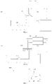
FIG. 1 is a schematic structural view of a refrigerator according to some embodiments of the present disclosure. -
FIG. 2 is a schematic structural view of the refrigerator according to other embodiments of the present disclosure. -
FIG. 3 is a schematic structural view of a working state of the refrigerator according to still other embodiments of the present disclosure. -
FIG. 4 is a schematic structural view of another working state of the refrigerator according to still other embodiments of the present disclosure. -
FIG. 5 is a schematic structural view of a valve of the refrigerator according to other embodiments of the present disclosure. -
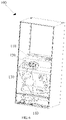
FIG. 6 is a perspective schematic view of the refrigerator according to yet other embodiments of the present disclosure. -
FIG. 7 is a partial structural schematic view of the refrigerator shown inFIG. 6 . - The technical solutions in the embodiments of the present disclosure will be clearly and completely described below in conjunction with the accompanying drawings in the embodiments of the present disclosure. It is clear that the embodiments described are only a part of the embodiments of the present disclosure, and not all of them. Based on the embodiments in the present disclosure, other embodiments obtained by those skilled in the art without creative work fall within the scope of the present disclosure.
- As shown in
FIG. 1 , arefrigerator 100 includes a first fresh-preservation chamber 110, anadsorption tower 120, avalve 130, and anair pump 140. An air inlet of theair pump 140 is in communication with the first fresh-preservation chamber 110, an air outlet of theair pump 140 is in communication with an air inlet of theadsorption tower 120 through an air inlet channel of thevalve 130, and the air inlet of theadsorption tower 120 is in communication with the first fresh-preservation chamber 110 through an air outlet channel of thevalve 130. When the air inlet channel of thevalve 130 is opened, theair pump 140 is configured to pressurize air in the first fresh-preservation chamber 110, and further transmit the air to theadsorption tower 120. In this case, theadsorption tower 120 may be configured to filter out oxygen in the air, the oxygen is discharged from an air outlet of theadsorption tower 120, and residual gas is adsorbed by theadsorption tower 120. When the air inlet channel of thevalve 130 is closed, theair pump 140 is configured to stop pressurizing the air and transmitting the air to theadsorption tower 120. In this case, the residual gas is released by theadsorption tower 120, and residual gas discharged into the first fresh-preservation chamber 110 through the air inlet of theadsorption tower 120 and the air outlet channel of thevalve 130. - In a fresh-preservation process of the refrigerator according to some embodiments of the present disclosure, the air in the first fresh-
preservation chamber 110 is extracted and the oxygen is filtered out, and the residual gas from which the oxygen is removed is returned to the first fresh-preservation chamber 110. In this way, an oxygen content of the first fresh-preservation chamber 110 may be reduced, such that a fresh preservation may be achieved by means of controlling the oxygen. Furthermore, a total air content of the first fresh-preservation chamber 110 may also be reduced, such that the air in the first fresh-preservation chamber 110 may be in a negative pressure state, thereby achieving the fresh preservation by means of the negative pressure. Thus, double fresh-preservation effect may be achieved by means of controlling the oxygen and the negative pressure. - In some embodiments, the
valve 130 includes the air inlet channel and the air outlet channel, and the air inlet channel and the air outlet channel are arranged separately, thus thevalve 130 includes at least three ports. As shown inFIG. 1 , the at least three ports include afirst port 131, asecond port 132, and athird port 133. Thefirst port 131 of thevalve 130 is in communication with the air inlet of theadsorption tower 120. Thesecond port 132 of thevalve 130 is in communication with the air outlet of theair pump 140. The air inlet channel is defined between thefirst port 131 and thesecond port 132 of thevalve 130, such that the air outlet of theair pump 140 is in communication with the air inlet of theadsorption tower 120 through the air inlet channel of thevalve 130. In addition, thethird port 133 of thevalve 130 is in communication with the first fresh-preservation chamber 110. The air outlet channel is defined between thethird port 133 of thevalve 130 and thefirst port 131 of thevalve 130, such that the air inlet of theadsorption tower 120 is in communication with the first fresh-preservation chamber 110 through the air outlet channel of thevalve 130. In this case, an air flow direction may be switched via thevalve 130. - In another embodiment, as shown in
FIG. 2 , thevalve 130 may include four ports, and the four ports may be thefirst port 131, thesecond port 132, thethird port 133, and afourth port 134. The air inlet of theadsorption tower 120 is in communication with thefirst port 131 and thefourth port 134. Thesecond port 132 of thevalve 130 is in communication with the air outlet of theair pump 140. The air inlet channel is defined between thefirst port 131 of thevalve 130 and thesecond port 132 of thevalve 130. Thethird port 133 of thevalve 130 is in communication with the first fresh-preservation chamber 110. The air outlet channel is defined between thefourth port 134 of thevalve 130 and thethird port 133 of thevalve 130. In this way, the air flow direction may be switched only by switching open/close states of the air inlet channel and the air outlet channel of thevalve 130, thereby controlling an inflow and outflow of the air in the first fresh-preservation chamber 110. - The number of the adsorption towers 120 is at least two. Oxygen in the air in the first fresh-
preservation chamber 110 may be continuously discharged by at least twoadsorption towers 120, and the residual gas adsorbed by theadsorption tower 120 may be continuously desorbed to the first fresh-preservation chamber 110, thus, the oxygen content of the first fresh-preservation chamber 110 may be controlled at a high efficiency and low time-consumption. Specifically, the at least twoadsorption towers 120 may include afirst adsorption tower 121 and asecond adsorption tower 122. - Accordingly, the
valve 130 defines a first air inlet channel and a first air outlet channel corresponding to eachfirst adsorption tower 121. Thevalve 130 further defines a second air inlet channel and a second air outlet channel corresponding to eachsecond adsorption tower 121. By alternately controlling the first air inlet channel to be opened while the second air inlet channel of thevalve 130 to be closed, or the first air outlet channel to be closed while the second air inlet channel to be opened, when one of thefirst adsorption tower 121 and thesecond adsorption tower 122 is adsorbing, the residual gas desorbed from the other of thefirst adsorption tower 121 and thesecond adsorption tower 122 flows into the first fresh-preservation chamber 110 through the air outlet channel, thus the oxygen content of the first fresh-preservation chamber 110 may be controlled at the high efficiency and low time-consumption. - At least two
first ports 131 of thevalve 130 and at least twothird ports 133 of thevalve 130 may also be provided. The number of thefirst ports 131 of thevalve 130 and the number of thethird ports 133 of thevalve 130 may be substantially equal to that of the adsorption towers 120. The air inlet of eachadsorption tower 120 may be connected to one of thethird ports 133. The air outlet channel is defined between eachfirst port 131 and a corresponding one of thethird ports 133. All of thethird ports 133 are in communication with the first fresh-preservation chamber 110. In addition, the number of thesecond ports 132 of thevalve 130 may be one, and the air inlet channel may be defined between eachfirst port 131 and thesecond port 132. - In another embodiment, as shown in
FIG. 3 and FIG. 4 , the number of the adsorption towers 120 may be two. Thevalve 130 may be a two-position five-way solenoid valve. In this way, it is easy to switch opened/closed states of the first air outlet channel, the second air outlet channel, the first air inlet channel, and the second air inlet channel of the valve 30 by the two-position five-way solenoid valve, such that working states of the twoadsorption towers 120 may be switched. In this case, when the one of thefirst adsorption tower 121 and thesecond adsorption tower 122 is adsorbing, the residual gas desorbed from the another of thefirst adsorption tower 121 and thesecond adsorption tower 122 flows into the first fresh-preservation chamber 110 through the air outlet channel, thus the oxygen in the air in the first fresh-preservation chamber 110 may be continuously discharged by means of controlling an operation of thevalve 130 and theair pump 140, and the residual gas adsorbed by theadsorption tower 120 may be continuously desorbed and transmitted to the first fresh-preservation chamber 110, thereby controlling the oxygen content of the first fresh-preservation chamber 110 at the high efficiency and low time-consumption. - As shown in
FIG. 5 , the two-position five-way solenoid valve may include twofirst ports 131, onesecond port 132, and twothird ports 133. One of the twofirst ports 131 is in communication with an air inlet of thefirst adsorption tower 121, and the other of the twofirst ports 131 is in communication with an air inlet of thesecond adsorption tower 122. The first air outlet channel is defined between thefirst port 131 connected to the air inlet of thefirst adsorption tower 121 and the correspondingthird port 133 which is corresponding to thefirst port 131 connected to the air inlet of thefirst adsorption tower 121. The second air outlet channel is defined between thefirst port 131 connected to the air inlet of thesecond adsorption tower 122 and the correspondingthird port 133 which is corresponding to thefirst port 131 connected to the air inlet of thesecond adsorption tower 122. All of thethird ports 133 are in communication with the first fresh-preservation chamber 110. The first air inlet channel is defined between thefirst port 131 connected to the air inlet of thefirst adsorption tower 121 and thesecond port 132. The second air inlet channel is defined between thefirst port 131 connected to the air inlet of thesecond adsorption tower 122 and thesecond port 132. - In the embodiment, the
adsorption tower 120 may be arranged with an adsorbing substance. When the adsorbing substance arranged in theadsorption tower 120 is in an adsorption state, the adsorbing substance has an adsorption capacity in adsorbing nitrogen greater than that of the oxygen. The adsorbing substance arranged in theadsorption tower 120 may be a zeolite molecular sieve particle. A polarity of the nitrogen in the air is greater than that of the oxygen. The zeolite molecular sieve has different adsorption capacities for the oxygen and nitrogen components in the air, such that the nitrogen may be preferentially adsorbed from the air by the zeolite molecular sieve, and the oxygen in the air may be filtered out. Therefore, the air entering from the air inlet of theadsorption tower 120, adsorbed by the zeolite molecular sieve and further flowing out of theadsorption tower 120 may have oxygen content greater than an oxygen content of the air, while the gas desorbed from the zeolite molecular sieve has oxygen content obviously less than the oxygen content of the air. In other words, the gas desorbed from the zeolite molecular sieve is gas having low oxygen content. The air desorbed from the zeolite molecular sieve may be further transmitted to the first fresh-preservation chamber 110, thereby reducing the oxygen content of the first fresh-preservation chamber 110, thus the fresh-preservation effect may be achieved. A particle size of the zeolite molecular sieve may be in a range from 0.4mm to 0.8mm, such as 0.5mm, 0.6mm, or 0.7mm. Of course, in other embodiments, the adsorbing substance arranged in theadsorption tower 120 may be a phosphate aluminum molecular sieve. - In some embodiments of the present disclosure, the oxygen content of the first fresh-
preservation chamber 110 may be controlled by means of an adsorption and desorption of theadsorption tower 120. Since the adsorbing substance has a characteristic that the adsorption capacity increases as a partial pressure of the adsorbed component increases, the adsorption and desorption may be achieved by means of a pressure change, thereby separating the air, that is, theadsorption tower 120 may be in the adsorption state or the desorption state by changing the pressure. Specifically, the pressure of the air is increased by theair pump 140, such that the air becomes compressed air, and the compressed air is in turn transmitted into theadsorption tower 120, thereby increasing the pressure in theadsorption tower 120 in a disguised manner. Therefore, theadsorption tower 120 may be in an adsorption stage, that is, at least a part of the oxygen in the compressed air is filtered out by theadsorption tower 120. When the compressed air is no longer transmitted to theadsorption tower 120 by theair pump 140, the pressure in theadsorption tower 120 decreases, and the adsorption capacity of theadsorption tower 120 in adsorbing the nitrogen and other substances is reduced, thus the substance adsorbed by theadsorption tower 120 is desorbed from theadsorption tower 120, and flows into the first fresh-preservation chamber 110 through the air inlet of theadsorption tower 120 and the air outlet channel of thevalve 130, that is, the residual gas desorbed from theadsorption tower 120 flows into the first fresh-preservation chamber 110, such that the oxygen content of the first fresh-preservation chamber 110 is reduced, thereby achieving the fresh preservation by means of controlling the oxygen. Furthermore, the total air content of the first fresh-preservation chamber 110 may also be reduced, such that the air in the first fresh-preservation chamber 110 may be in the negative pressure state, thereby achieving the fresh preservation by means of the negative pressure. In this way, the double fresh-preservation effect may be achieved by means of controlling the oxygen and the negative pressure. In the embodiment, a pressure pressurized by the air pump on the air is in a range from 0.12 MPa to 0.2 MPa, according to the particle size of the zeolite molecule. - The
air pump 140 may be miniaturized according to a corresponding relationship between the particle size of the zeolite molecular sieve and pressurization on the air by theair pump 140, such that a power consumption of therefrigerator 100 and a noise are reduced. If the particle size of the zeolite molecular sieve is too small, a transmission resistance of the air flow is too large. In this case, to increase the pressure appropriately, the particle size of the zeolite molecular sieve filled in theadsorption tower 120 may be uniform and moderate. For example, the particle size of the zeolite molecular sieve is set in a range from 0.4mm to 0.8mm, such that theair pump 140 is not required to increase excessive pressure on the air, thus theair pump 140 may be miniaturized, thereby reducing the power consumption of therefrigerator 100 and the noise. - In the embodiment, a shape of the
adsorption tower 120 may be substantially cylindrical. Of course, theadsorption tower 120 may also be in other regular shapes, such as cube, cuboid. Theadsorption tower 120 may also be in irregular shape. - The adsorption capacity of the
adsorption tower 120 may be controlled by means of controlling a size of theadsorption tower 120. The size of theadsorption tower 120 may be controlled in an appropriate range, thus the adsorption capacity of theadsorption tower 120 may not only be ensured, but also a volume of theadsorption tower 120 may be small. Specifically, a diameter of theadsorption tower 120 may be in a range from 20mm to 30mm. A height of theadsorption tower 120 may be in a range from 150mm to 300mm. Optionally, the diameter of theadsorption tower 120 may be 20mm, 22mm, 24mm, 25mm, or 27mm. The height of theadsorption tower 120 may be 160mm, 186mm, 200mm, 230mm, or 250mm. - A transmission flow of the
air pump 140 is designed correspondingly to a small size design of theadsorption tower 120. A contact duration between molecules in the compressed air and the adsorbing substances in theadsorption tower 120 may be changed by changing the transmission flow of theair pump 140, thereby changing an adsorption efficiency of theadsorption tower 120 for the compressed air. If a transmission speed is too fast, the contact duration between the molecules in the compressed air and the adsorbing substance will be too short, which is not conducive to the adsorption of the air, and the adsorption efficiency is reduced. If the transmission speed is too low, the volume of theadsorption tower 120 will increase. Therefore, the transmission flow should be controlled in an appropriate range. In this embodiment, the transmission flow of theair pump 140 is in a range from 5L/min to 15L/min, such as 7L/min, 9L/min, or 11L/min. Of course, in order to ensure the adsorption efficiency of theadsorption tower 120, a ratio of the transmission flow of theair pump 140 per second to the volume of theadsorption tower 120 is in a range from 1.2 to 2.2. - The first fresh-
preservation chamber 110 may be a sealed space, such that the air in the first fresh-preservation chamber 110 is not in communication with atmosphere. At least a part of the oxygen in the air in the first fresh-preservation chamber 110 may be removed, and the air from which the oxygen is removed is returned to the first fresh-preservation chamber 110 again. In this way, the oxygen content of the first fresh-preservation chamber 110 is reduced, thereby achieving the fresh preservation by means of controlling the oxygen. Furthermore, the total air content of the first fresh-preservation chamber 110 may also be reduced, such that the air in the first fresh-preservation chamber 110 may be in the negative pressure state, thereby achieving the fresh preservation by means of the negative pressure. Thus, the double fresh-preservation effect may be achieved by means of controlling the oxygen and the negative pressure. - The number of the first fresh-
preservation chamber 110 may be one or more. The first fresh-preservation chamber 110 may be a fresh-preservation chamber configured to store food, such as vegetables, fruits, etc. The oxygen content of the first fresh-preservation chamber 110 may be controlled to a low level, such that a respiration rate of food stored in the first fresh-preservation chamber 110 may be reduced, and a metabolism of the food may be inhibited, thereby achieving the fresh-preservation effect, and thus deterioration of the food and reproduction of bacteria are inhibited. - The first fresh-
preservation chamber 110 may be arranged with a first sensor. The first sensor may be configured to detect the oxygen content of the first fresh-preservation chamber 110. When the oxygen content of the first fresh-preservation chamber 110 detected by the first sensor is greater than a first threshold, theair pump 140 and thevalve 130 may be controlled, and the oxygen content of the first fresh-preservation room 110 may be cooperatively controlled by theair pump 140, thevalve 130, and theadsorption tower 120, so as to reduce the oxygen content of the first fresh-preservation room 110. When the oxygen content of the first fresh-preservation chamber 110 detected by the first sensor is less than a second threshold, theair pump 140 may be controlled to stop operating, that is, the oxygen content of the first fresh-preservation room 110 is no longer cooperatively controlled by theair pump 140, thevalve 130, and theadsorption tower 120. The first sensor is connected to theair pump 140. The first sensor may be further connected to thevalve 130. - The first fresh-
preservation chamber 110 may be further arranged with a second sensor. The second sensor is configured to detect whether the first fresh-preservation chamber 110 is opened. When the second sensor detects that the firstfresh chamber 110 is opened, theair pump 140 and thevalve 130 may be controlled, and the oxygen content of the first fresh-preservation room 110 may be cooperatively controlled by theair pump 140, thevalve 130, and theadsorption tower 120, so as to reduce the oxygen content of the first fresh-preservation room 110. The second sensor is connected to theair pump 140. The first sensor may be further connected to thevalve 130. - In the embodiment, the first fresh-
preservation chamber 110 further includes a controller. The controller may be connected to theair pump 140 and thevalve 130. The controller may be configured to control the operation of theair pump 140. Further, the controller may be configured to control the opened/closed state of the air inlet channel and the air outlet channel of thevalve 130. - Furthermore, the controller may also be connected to the first sensor, and configured to receive data detected by the first sensor. Of course, according to the detected data, the controller may also be configured to analyze whether to control the oxygen content of the first fresh-
preservation room 110 by theair pump 140, thevalve 130, and theadsorption tower 120. Further, according to an analysis result, the controller may also be configured to control the operations of theair pump 140 and thevalve 130. - Furthermore, the controller may also be connected to the second sensor, and configured to receive data detected by the second sensor. Of course, according to the data detected by the second sensor, the controller may be configured to analyze whether to control the oxygen content of the first fresh-
preservation room 110 by theair pump 140, thevalve 130, and theadsorption tower 120. Further, according to an analysis result, the controller may also be configured to control the operations of theair pump 140 and thevalve 130. - In the embodiment, an air outlet switch may also be arranged at the air outlet of the
adsorption tower 120. When theadsorption tower 120 is in the adsorption state, the air outlet switch is switched on, such that gas which is not adsorbed by the adsorbing substance in theadsorption tower 120 may be discharged from the air outlet of theadsorption tower 120. When theadsorption tower 120 is in the desorption state, the air outlet switch is switched off, such that air desorbed from theadsorption tower 120 can only flow into the first fresh-preservation chamber 110 through the air inlet of theadsorption tower 120 and the air inlet channel of thevalve 130. Besides, it is possible to prevent outside air from entering into theadsorption tower 120 through the air outlet of theadsorption tower 120, such that it is possible to prevent the outside air from flowing into the first fresh-preservation chamber 110 together with the air desorbed from theadsorption tower 120, thereby ensuring an efficiency of reducing the oxygen content of the first fresh-preservation chamber 110. - In the embodiment, the
refrigerator 100 further includes a second fresh-preservation chamber 150. The air outlet of theadsorption tower 120 is in communication with the second fresh-preservation chamber 150. In other words, the second fresh-preservation chamber 150 may be configured to receive oxygen-enriched air which is discharged from theadsorption tower 120, such that an oxygen content of the second fresh-preservation chamber 150 is increased. The second fresh-preservation chamber 150 may be configured to store meats. A fresh-preservation color of meats stored in the second fresh-preservation room 150 may be ensured to be bright by means of increasing the oxygen content of the second fresh-preservation room 150. - As shown in
FIG. 6 andFIG. 7 , specifically, the first fresh-preservation chamber 110 is disposed in therefrigerator 100 in a manner of a drawer. Theadsorption tower 120 and thevalve 130 are disposed at a back of the first fresh-preservation chamber 110, that is, theadsorption tower 120 and thevalve 130 are disposed at a side of the first fresh-preservation chamber 110 away from therefrigerator 100. In this way, when the first fresh-preservation chamber 110 is opened, an impact on a position of thevalve 130 and theadsorption tower 120 may be reduced, and an impact on a connection relationship among thevalve 130, theadsorption tower 120, and theair pump 140 may also be reduced. Theair pump 140 is disposed at a bottom of therefrigerator 100. The first fresh-preservation chamber 110 is connected to the air inlet of theair pump 140 by an air tube, the air outlet of theair pump 140 is connected to thevalve 130 by another air tube, and theadsorption tower 120 is connected to thevalve 130 by an additional air tube. In this way, when the first fresh-preservation chamber 110 is opened, connections among the air inlets and the air outlets are not affected. The air tube may be a soft air tube or a rigid air tube. - Furthermore, when the number of the adsorption towers 120 is two, the two
adsorption towers 120 are arranged side by side, and all of the air inlets of the adsorption towers 120 are arranged to face the same direction, such that a structure and a layout of theentire refrigerator 100 are compact. - In short, in the fresh-preservation process of the refrigerator, the air in the first fresh-
preservation chamber 110 is extracted and the oxygen is filtered out, and the residual gas from which the oxygen is removed is returned to the first fresh-preservation chamber 110. In this way, the oxygen content of the first fresh-preservation chamber 110 may be reduced, such that the fresh preservation may be achieved by means of controlling the oxygen. Furthermore, the total air content of the first fresh-preservation chamber 110 may also be reduced, such that the air in the first fresh-preservation chamber 110 may be in the negative pressure state, thereby achieving the fresh preservation by means of the negative pressure, thus double fresh-preservation effect may be achieved by means of controlling the oxygen and the negative pressure. - The above are only embodiments of the present disclosure and are not intended to limit the scope of the present disclosure. Any equivalent structural changes made under the concept of the present disclosure, using the contents of the specification of the present disclosure and the accompanying drawings, or applied directly/indirectly in other related fields of technology are included in the scope of protection of the present disclosure.
Claims (10)
- A refrigerator, comprising:a first fresh-preservation chamber, an adsorption tower, a valve, and an air pump;wherein an air inlet of the air pump is in communication with the first fresh-preservation chamber, an air outlet of the air pump is in communication with an air inlet of the adsorption tower through an air inlet channel of the valve, and the air inlet of the adsorption tower is in communication with the first fresh-preservation chamber through an air outlet channel of the valve;in response to the air inlet channel of the valve being opened, the air pump is configured to pressurize air in the first fresh-preservation chamber, and transmit the air to the adsorption tower, the adsorption tower is configured to filter out oxygen in the air, the oxygen is discharged from an air outlet of the adsorption tower, and residual gas is adsorbed by the adsorption tower; andin response to the air inlet channel of the valve being closed, the air pump is configured to stop pressurizing the air and transmitting the air to the adsorption tower, the residual gas is released by the adsorption tower, and discharged to the first fresh-preservation chamber through the air inlet of the adsorption tower and the air outlet channel of the valve.
- The refrigerator as claimed in claim 1, wherein the number of the adsorption towers is at least two, and the at least two adsorption towers comprise a first adsorption tower and a second adsorption tower;the valve defines a first air inlet channel and a first air outlet channel corresponding to each first adsorption tower, and defines a second air inlet channel and a second air outlet channel corresponding to each second adsorption tower; andthe valve is alternately switched between a state that the first air inlet channel is opened while the second air inlet channel of the valve is closed and a state that the first air outlet channel is closed while the second air inlet channel is opened.
- The refrigerator as claimed in claim 2, wherein the number of the adsorption towers is two, and the valve is a two-position five-way solenoid valve.
- The refrigerator as claimed in claim 2, wherein the at least two adsorption towers are arranged side by side, and all of the air inlets of the adsorption towers are arranged to face a same direction.
- The refrigerator as claimed in claim 1, wherein the adsorption tower is arranged with a zeolite molecular sieve particle, and a particle size of the zeolite molecular sieve particle is in a range from 0.4mm to 0.8mm; and
a pressure pressurized by the air pump on the air is in a range from 0.12 MPa to 0.2 MPa. - The refrigerator as claimed in claim 5, wherein a ratio of a transmission flow of the air pump per second to a volume of the adsorption tower is in a range from 1.2 to 2.2.
- The refrigerator as claimed in claim 6, wherein a shape of the adsorption tower is substantially cylindrical, a diameter of the adsorption tower is in a range from 20mm to 30mm, and a height of the adsorption tower is in a range from 150mm to 300mm; and
a transmission flow of the air pump is in a range from 5L/min to 15L/min. - The refrigerator as claimed in claim 1, further comprising: a second fresh-preservation chamber;
wherein the air outlet of the adsorption tower is in communication with the second fresh-preservation chamber. - The refrigerator as claimed in claim 1, wherein the first fresh-preservation chamber is arranged with a first sensor, and the first sensor is configured to detect the oxygen content of the first fresh-preservation chamber and is connected to the air pump.
- The refrigerator as claimed in claim 1, wherein the first fresh-preservation chamber is arranged with a second sensor, and the second sensor is configured to detect whether the first fresh-preservation chamber is opened and is connected to the air pump.
Applications Claiming Priority (2)
| Application Number | Priority Date | Filing Date | Title |
|---|---|---|---|
| CN201911339640.4A CN113091362A (en) | 2019-12-23 | 2019-12-23 | A kind of refrigerator |
| PCT/CN2020/134690 WO2021129386A1 (en) | 2019-12-23 | 2020-12-08 | Refrigerator |
Publications (3)
| Publication Number | Publication Date |
|---|---|
| EP4063767A1 true EP4063767A1 (en) | 2022-09-28 |
| EP4063767A4 EP4063767A4 (en) | 2022-12-21 |
| EP4063767B1 EP4063767B1 (en) | 2024-12-04 |
Family
ID=76573646
Family Applications (1)
| Application Number | Title | Priority Date | Filing Date |
|---|---|---|---|
| EP20904758.8A Active EP4063767B1 (en) | 2019-12-23 | 2020-12-08 | Refrigerator |
Country Status (5)
| Country | Link |
|---|---|
| US (1) | US12392540B2 (en) |
| EP (1) | EP4063767B1 (en) |
| JP (1) | JP7533988B2 (en) |
| CN (1) | CN113091362A (en) |
| WO (1) | WO2021129386A1 (en) |
Families Citing this family (6)
| Publication number | Priority date | Publication date | Assignee | Title |
|---|---|---|---|---|
| CN116212585B (en) * | 2021-12-02 | 2025-11-11 | 合肥美的电冰箱有限公司 | Pressure swing adsorption deoxidizing device, fresh-keeping device and refrigerator |
| CN217876676U (en) * | 2022-01-29 | 2022-11-22 | 青岛海尔电冰箱有限公司 | Refrigerator with a door |
| CN116558203A (en) * | 2022-01-29 | 2023-08-08 | 青岛海尔电冰箱有限公司 | Gas processing device and refrigerator having the same |
| CN116558202A (en) * | 2022-01-29 | 2023-08-08 | 青岛海尔电冰箱有限公司 | refrigerator |
| CN119901107A (en) * | 2023-10-26 | 2025-04-29 | 深圳洛克创新科技有限公司 | Fluid processing device, fresh-keeping device and control method, storage medium, electronic device |
| CN118960308B (en) * | 2024-07-29 | 2025-08-05 | 宁波方太厨具有限公司 | A nitrogen production control method, system and refrigerator |
Family Cites Families (39)
| Publication number | Priority date | Publication date | Assignee | Title |
|---|---|---|---|---|
| JPS5914749A (en) * | 1982-07-15 | 1984-01-25 | Hitachi Ltd | How to adjust the atmosphere in a storage room |
| JPH0282083A (en) * | 1988-09-19 | 1990-03-22 | Ryuhei Fukuda | Vessel maintaining nitrogen enriched environmental condition |
| JPH02203185A (en) * | 1989-01-31 | 1990-08-13 | Toshiba Corp | Refrigerator |
| US5451248A (en) * | 1990-07-19 | 1995-09-19 | The Boc Group Plc | Storage and transportation of goods under controlled atmospheres |
| JPH1121107A (en) * | 1997-07-01 | 1999-01-26 | Sanyo Electric Co Ltd | Air quality activating device |
| CN2312064Y (en) * | 1997-10-24 | 1999-03-31 | 殷小平 | Single adsorption and pressure control type nitrogen producing equipment |
| CN100523655C (en) * | 2001-02-21 | 2009-08-05 | 三菱化学株式会社 | Adsorption heat pump, use of adsorbent for adsorption heat pump, use method of adsorbent for adsorption heat pump, and vehicle air conditioner |
| US8258137B2 (en) * | 2008-01-29 | 2012-09-04 | Katholieke Universiteit Leuven | Process for release of biologically active species from mesoporous oxide systems |
| CN102679616B (en) * | 2012-02-17 | 2014-07-16 | 南京工业大学 | Two-stage adsorption refrigeration cycle system |
| US9982927B2 (en) * | 2013-11-04 | 2018-05-29 | Lg Electronics Inc. | Refrigerator and method of controlling the same |
| KR20160008778A (en) * | 2014-07-15 | 2016-01-25 | 김영선 | Self generation electricity air conditioner for Car |
| JP5862737B1 (en) * | 2014-09-16 | 2016-02-16 | ダイキン工業株式会社 | Container refrigeration equipment |
| JP5971296B2 (en) * | 2014-09-16 | 2016-08-17 | ダイキン工業株式会社 | Container refrigeration equipment |
| EP3258192B1 (en) * | 2015-02-27 | 2021-11-10 | Daikin Industries, Ltd. | Refrigeration device for container |
| JP6056923B1 (en) * | 2015-08-28 | 2017-01-11 | ダイキン工業株式会社 | Container refrigeration equipment |
| US9841224B2 (en) * | 2016-01-18 | 2017-12-12 | Haier Us Appliance Solutions, Inc. | Refrigerator appliances with passive storage compartments |
| CN105923613B (en) | 2016-04-27 | 2018-02-02 | 青岛海尔股份有限公司 | nitrogen-making device and refrigerator |
| CN105953495B (en) | 2016-04-27 | 2018-07-13 | 青岛海尔股份有限公司 | Refrigerating device and its control method |
| CN106052291B (en) | 2016-05-26 | 2019-01-18 | 青岛海尔股份有限公司 | Refrigerating equipment and its control method |
| CN106016950B (en) | 2016-05-26 | 2018-08-10 | 青岛海尔股份有限公司 | The nitrogen control method processed and device of refrigerator |
| CN106052254B (en) | 2016-05-30 | 2018-10-12 | 青岛海尔股份有限公司 | Refrigerating device |
| CN106091532B (en) | 2016-05-31 | 2019-01-18 | 青岛海尔股份有限公司 | Nitrogen control method and refrigerating equipment processed for refrigerating equipment |
| CN106091519A (en) | 2016-05-31 | 2016-11-09 | 青岛海尔股份有限公司 | Refrigerator |
| CN106115637B (en) | 2016-06-20 | 2018-04-20 | 青岛海尔股份有限公司 | Refrigerating equipment |
| CN106288637B (en) | 2016-08-16 | 2019-07-02 | 青岛海尔股份有限公司 | Nitrogen production control method for refrigerating and freezing equipment and refrigerating and freezing equipment |
| CN206131588U (en) | 2016-09-05 | 2017-04-26 | 合肥海尔电冰箱有限公司 | Cold -stored refrigeration device |
| CN106247731B (en) | 2016-09-28 | 2020-07-28 | 青岛海尔股份有限公司 | Refrigerator and freezer |
| CN106642968A (en) * | 2016-11-11 | 2017-05-10 | 青岛海尔股份有限公司 | Nitrogen production control method for refrigerating and freezing equipment and refrigerating and freezing equipment |
| CN106642910B (en) | 2016-11-11 | 2019-08-02 | 青岛海尔股份有限公司 | Temperature control method for refrigerating and freezing equipment and refrigerating and freezing equipment |
| CN106642909B (en) | 2016-11-11 | 2019-08-27 | 青岛海尔股份有限公司 | Refrigerators & Freezer Storage Boxes |
| CN206291580U (en) * | 2016-12-02 | 2017-06-30 | 青岛海尔股份有限公司 | Article-storage device with fresh keep-alive storage function |
| CN206352919U (en) * | 2016-12-02 | 2017-07-25 | 青岛海尔股份有限公司 | Refrigerating equipment |
| UY37508A (en) * | 2016-12-05 | 2018-06-29 | Pace Int Llc | METHOD AND SYSTEM TO TREAT AGRICULTURAL PRODUCTS |
| JP6917045B2 (en) * | 2016-12-12 | 2021-08-11 | アクア株式会社 | refrigerator |
| CN109464877B (en) * | 2017-09-08 | 2025-11-18 | 霍尼韦尔特性材料和技术(中国)有限公司 | Methods for changing the concentration of nitrogen and oxygen in gases, oxygen reduction devices and methods, and refrigerators |
| CN207849867U (en) * | 2018-02-11 | 2018-09-11 | 宁夏大学 | A kind of preservation device and system |
| CN109613859B (en) * | 2018-12-06 | 2021-12-28 | 深圳市德达医疗科技集团有限公司 | Molecular sieve oxygen generator and control system and method thereof |
| CN211876472U (en) * | 2019-12-23 | 2020-11-06 | 广东美的白色家电技术创新中心有限公司 | A kind of refrigerator |
| CN113446800B (en) * | 2020-03-24 | 2022-05-31 | 合肥华凌股份有限公司 | Fresh-keeping device and refrigerator |
-
2019
- 2019-12-23 CN CN201911339640.4A patent/CN113091362A/en active Pending
-
2020
- 2020-12-08 JP JP2022537804A patent/JP7533988B2/en active Active
- 2020-12-08 EP EP20904758.8A patent/EP4063767B1/en active Active
- 2020-12-08 WO PCT/CN2020/134690 patent/WO2021129386A1/en not_active Ceased
-
2022
- 2022-06-17 US US17/843,905 patent/US12392540B2/en active Active
Also Published As
| Publication number | Publication date |
|---|---|
| US20220357090A1 (en) | 2022-11-10 |
| JP2023506564A (en) | 2023-02-16 |
| JP7533988B2 (en) | 2024-08-14 |
| WO2021129386A1 (en) | 2021-07-01 |
| EP4063767B1 (en) | 2024-12-04 |
| EP4063767A4 (en) | 2022-12-21 |
| CN113091362A (en) | 2021-07-09 |
| US12392540B2 (en) | 2025-08-19 |
Similar Documents
| Publication | Publication Date | Title |
|---|---|---|
| EP4063767A1 (en) | Refrigerator | |
| CN211876472U (en) | A kind of refrigerator | |
| KR20180130101A (en) | Refrigerator | |
| US11517022B2 (en) | Internal air adjustment device | |
| CN113218023B (en) | Air composition regulator | |
| CN109464877B (en) | Methods for changing the concentration of nitrogen and oxygen in gases, oxygen reduction devices and methods, and refrigerators | |
| JP2008238076A (en) | Pressure swing adsorption type oxygen concentrator | |
| CN215305120U (en) | Oxygen control device and kitchen appliance | |
| CN215605075U (en) | An oxygen control device and kitchen appliance | |
| CN215138351U (en) | Circulating oxygen exhaust devices and kitchen appliances | |
| WO2022111299A1 (en) | Circulating oxygen discharge device, and kitchen appliance | |
| EP3473956B1 (en) | Refrigeration and freezing device | |
| CN114532866A (en) | Oxygen control device and kitchen appliance | |
| US11316219B2 (en) | Metal air battery including multi module air supply unit | |
| CN207462922U (en) | Oxygen device and refrigerator drop | |
| US10258919B2 (en) | Oxygen separator with improved efficiency | |
| CN210352988U (en) | Portable fresh-keeping device and fresh-keeping system | |
| KR100565210B1 (en) | Gas separation device | |
| CN103723684B (en) | Oxygen generator with cyclic filtration function | |
| JPH11347336A (en) | Small-size gas separation device | |
| CN218908391U (en) | Automatic condiment bottle and automatic condiment feeding device using same | |
| KR20040092269A (en) | System for separating a mixed gas | |
| CN118816453A (en) | Air conditioning mechanism, fresh-keeping drawer and refrigerator | |
| CN119034424A (en) | Small-sized pressure swing adsorption nitrogen and oxygen preparation system | |
| KR20060025723A (en) | Gas separation device |
Legal Events
| Date | Code | Title | Description |
|---|---|---|---|
| STAA | Information on the status of an ep patent application or granted ep patent |
Free format text: STATUS: THE INTERNATIONAL PUBLICATION HAS BEEN MADE |
|
| PUAI | Public reference made under article 153(3) epc to a published international application that has entered the european phase |
Free format text: ORIGINAL CODE: 0009012 |
|
| STAA | Information on the status of an ep patent application or granted ep patent |
Free format text: STATUS: REQUEST FOR EXAMINATION WAS MADE |
|
| 17P | Request for examination filed |
Effective date: 20220620 |
|
| AK | Designated contracting states |
Kind code of ref document: A1 Designated state(s): AL AT BE BG CH CY CZ DE DK EE ES FI FR GB GR HR HU IE IS IT LI LT LU LV MC MK MT NL NO PL PT RO RS SE SI SK SM TR |
|
| A4 | Supplementary search report drawn up and despatched |
Effective date: 20221123 |
|
| RIC1 | Information provided on ipc code assigned before grant |
Ipc: F25D 25/02 20060101ALN20221117BHEP Ipc: F25D 17/04 20060101ALI20221117BHEP Ipc: F25D 11/00 20060101AFI20221117BHEP |
|
| DAV | Request for validation of the european patent (deleted) | ||
| DAX | Request for extension of the european patent (deleted) | ||
| GRAP | Despatch of communication of intention to grant a patent |
Free format text: ORIGINAL CODE: EPIDOSNIGR1 |
|
| STAA | Information on the status of an ep patent application or granted ep patent |
Free format text: STATUS: GRANT OF PATENT IS INTENDED |
|
| RIC1 | Information provided on ipc code assigned before grant |
Ipc: F25D 25/02 20060101ALN20240628BHEP Ipc: F25D 17/04 20060101ALI20240628BHEP Ipc: F25D 11/00 20060101AFI20240628BHEP |
|
| INTG | Intention to grant announced |
Effective date: 20240712 |
|
| GRAS | Grant fee paid |
Free format text: ORIGINAL CODE: EPIDOSNIGR3 |
|
| GRAA | (expected) grant |
Free format text: ORIGINAL CODE: 0009210 |
|
| STAA | Information on the status of an ep patent application or granted ep patent |
Free format text: STATUS: THE PATENT HAS BEEN GRANTED |
|
| AK | Designated contracting states |
Kind code of ref document: B1 Designated state(s): AL AT BE BG CH CY CZ DE DK EE ES FI FR GB GR HR HU IE IS IT LI LT LU LV MC MK MT NL NO PL PT RO RS SE SI SK SM TR |
|
| REG | Reference to a national code |
Ref country code: CH Ref legal event code: EP |
|
| REG | Reference to a national code |
Ref country code: DE Ref legal event code: R096 Ref document number: 602020042787 Country of ref document: DE |
|
| REG | Reference to a national code |
Ref country code: IE Ref legal event code: FG4D |
|
| REG | Reference to a national code |
Ref country code: LT Ref legal event code: MG9D |
|
| REG | Reference to a national code |
Ref country code: NL Ref legal event code: MP Effective date: 20241204 |
|
| PG25 | Lapsed in a contracting state [announced via postgrant information from national office to epo] |
Ref country code: HR Free format text: LAPSE BECAUSE OF FAILURE TO SUBMIT A TRANSLATION OF THE DESCRIPTION OR TO PAY THE FEE WITHIN THE PRESCRIBED TIME-LIMIT Effective date: 20241204 |
|
| PG25 | Lapsed in a contracting state [announced via postgrant information from national office to epo] |
Ref country code: FI Free format text: LAPSE BECAUSE OF FAILURE TO SUBMIT A TRANSLATION OF THE DESCRIPTION OR TO PAY THE FEE WITHIN THE PRESCRIBED TIME-LIMIT Effective date: 20241204 |
|
| PG25 | Lapsed in a contracting state [announced via postgrant information from national office to epo] |
Ref country code: BG Free format text: LAPSE BECAUSE OF FAILURE TO SUBMIT A TRANSLATION OF THE DESCRIPTION OR TO PAY THE FEE WITHIN THE PRESCRIBED TIME-LIMIT Effective date: 20241204 |
|
| PG25 | Lapsed in a contracting state [announced via postgrant information from national office to epo] |
Ref country code: ES Free format text: LAPSE BECAUSE OF FAILURE TO SUBMIT A TRANSLATION OF THE DESCRIPTION OR TO PAY THE FEE WITHIN THE PRESCRIBED TIME-LIMIT Effective date: 20241204 |
|
| PG25 | Lapsed in a contracting state [announced via postgrant information from national office to epo] |
Ref country code: NO Free format text: LAPSE BECAUSE OF FAILURE TO SUBMIT A TRANSLATION OF THE DESCRIPTION OR TO PAY THE FEE WITHIN THE PRESCRIBED TIME-LIMIT Effective date: 20250304 |
|
| PG25 | Lapsed in a contracting state [announced via postgrant information from national office to epo] |
Ref country code: GR Free format text: LAPSE BECAUSE OF FAILURE TO SUBMIT A TRANSLATION OF THE DESCRIPTION OR TO PAY THE FEE WITHIN THE PRESCRIBED TIME-LIMIT Effective date: 20250305 Ref country code: LV Free format text: LAPSE BECAUSE OF FAILURE TO SUBMIT A TRANSLATION OF THE DESCRIPTION OR TO PAY THE FEE WITHIN THE PRESCRIBED TIME-LIMIT Effective date: 20241204 |
|
| PG25 | Lapsed in a contracting state [announced via postgrant information from national office to epo] |
Ref country code: RS Free format text: LAPSE BECAUSE OF FAILURE TO SUBMIT A TRANSLATION OF THE DESCRIPTION OR TO PAY THE FEE WITHIN THE PRESCRIBED TIME-LIMIT Effective date: 20250304 |
|
| PG25 | Lapsed in a contracting state [announced via postgrant information from national office to epo] |
Ref country code: NL Free format text: LAPSE BECAUSE OF FAILURE TO SUBMIT A TRANSLATION OF THE DESCRIPTION OR TO PAY THE FEE WITHIN THE PRESCRIBED TIME-LIMIT Effective date: 20241204 |
|
| REG | Reference to a national code |
Ref country code: AT Ref legal event code: MK05 Ref document number: 1748572 Country of ref document: AT Kind code of ref document: T Effective date: 20241204 |
|
| PG25 | Lapsed in a contracting state [announced via postgrant information from national office to epo] |
Ref country code: SM Free format text: LAPSE BECAUSE OF FAILURE TO SUBMIT A TRANSLATION OF THE DESCRIPTION OR TO PAY THE FEE WITHIN THE PRESCRIBED TIME-LIMIT Effective date: 20241204 |
|
| PG25 | Lapsed in a contracting state [announced via postgrant information from national office to epo] |
Ref country code: PL Free format text: LAPSE BECAUSE OF FAILURE TO SUBMIT A TRANSLATION OF THE DESCRIPTION OR TO PAY THE FEE WITHIN THE PRESCRIBED TIME-LIMIT Effective date: 20241204 |
|
| PG25 | Lapsed in a contracting state [announced via postgrant information from national office to epo] |
Ref country code: IS Free format text: LAPSE BECAUSE OF FAILURE TO SUBMIT A TRANSLATION OF THE DESCRIPTION OR TO PAY THE FEE WITHIN THE PRESCRIBED TIME-LIMIT Effective date: 20250404 |
|
| PG25 | Lapsed in a contracting state [announced via postgrant information from national office to epo] |
Ref country code: PT Free format text: LAPSE BECAUSE OF FAILURE TO SUBMIT A TRANSLATION OF THE DESCRIPTION OR TO PAY THE FEE WITHIN THE PRESCRIBED TIME-LIMIT Effective date: 20250404 |
|
| PG25 | Lapsed in a contracting state [announced via postgrant information from national office to epo] |
Ref country code: EE Free format text: LAPSE BECAUSE OF FAILURE TO SUBMIT A TRANSLATION OF THE DESCRIPTION OR TO PAY THE FEE WITHIN THE PRESCRIBED TIME-LIMIT Effective date: 20241204 |
|
| PG25 | Lapsed in a contracting state [announced via postgrant information from national office to epo] |
Ref country code: RO Free format text: LAPSE BECAUSE OF FAILURE TO SUBMIT A TRANSLATION OF THE DESCRIPTION OR TO PAY THE FEE WITHIN THE PRESCRIBED TIME-LIMIT Effective date: 20241204 Ref country code: AT Free format text: LAPSE BECAUSE OF FAILURE TO SUBMIT A TRANSLATION OF THE DESCRIPTION OR TO PAY THE FEE WITHIN THE PRESCRIBED TIME-LIMIT Effective date: 20241204 |
|
| PG25 | Lapsed in a contracting state [announced via postgrant information from national office to epo] |
Ref country code: SK Free format text: LAPSE BECAUSE OF FAILURE TO SUBMIT A TRANSLATION OF THE DESCRIPTION OR TO PAY THE FEE WITHIN THE PRESCRIBED TIME-LIMIT Effective date: 20241204 |
|
| PG25 | Lapsed in a contracting state [announced via postgrant information from national office to epo] |
Ref country code: CZ Free format text: LAPSE BECAUSE OF FAILURE TO SUBMIT A TRANSLATION OF THE DESCRIPTION OR TO PAY THE FEE WITHIN THE PRESCRIBED TIME-LIMIT Effective date: 20241204 |
|
| PG25 | Lapsed in a contracting state [announced via postgrant information from national office to epo] |
Ref country code: IT Free format text: LAPSE BECAUSE OF FAILURE TO SUBMIT A TRANSLATION OF THE DESCRIPTION OR TO PAY THE FEE WITHIN THE PRESCRIBED TIME-LIMIT Effective date: 20241204 |
|
| REG | Reference to a national code |
Ref country code: CH Ref legal event code: PL |
|
| PG25 | Lapsed in a contracting state [announced via postgrant information from national office to epo] |
Ref country code: LU Free format text: LAPSE BECAUSE OF NON-PAYMENT OF DUE FEES Effective date: 20241208 |
|
| REG | Reference to a national code |
Ref country code: DE Ref legal event code: R097 Ref document number: 602020042787 Country of ref document: DE |
|
| PG25 | Lapsed in a contracting state [announced via postgrant information from national office to epo] |
Ref country code: SE Free format text: LAPSE BECAUSE OF FAILURE TO SUBMIT A TRANSLATION OF THE DESCRIPTION OR TO PAY THE FEE WITHIN THE PRESCRIBED TIME-LIMIT Effective date: 20241204 |
|
| PG25 | Lapsed in a contracting state [announced via postgrant information from national office to epo] |
Ref country code: MC Free format text: LAPSE BECAUSE OF FAILURE TO SUBMIT A TRANSLATION OF THE DESCRIPTION OR TO PAY THE FEE WITHIN THE PRESCRIBED TIME-LIMIT Effective date: 20241204 |
|
| REG | Reference to a national code |
Ref country code: BE Ref legal event code: MM Effective date: 20241231 |
|
| PG25 | Lapsed in a contracting state [announced via postgrant information from national office to epo] |
Ref country code: DK Free format text: LAPSE BECAUSE OF FAILURE TO SUBMIT A TRANSLATION OF THE DESCRIPTION OR TO PAY THE FEE WITHIN THE PRESCRIBED TIME-LIMIT Effective date: 20241204 |
|
| PLBE | No opposition filed within time limit |
Free format text: ORIGINAL CODE: 0009261 |
|
| STAA | Information on the status of an ep patent application or granted ep patent |
Free format text: STATUS: NO OPPOSITION FILED WITHIN TIME LIMIT |
|
| PG25 | Lapsed in a contracting state [announced via postgrant information from national office to epo] |
Ref country code: BE Free format text: LAPSE BECAUSE OF NON-PAYMENT OF DUE FEES Effective date: 20241231 |
|
| PG25 | Lapsed in a contracting state [announced via postgrant information from national office to epo] |
Ref country code: CH Free format text: LAPSE BECAUSE OF NON-PAYMENT OF DUE FEES Effective date: 20241231 |
|
| PG25 | Lapsed in a contracting state [announced via postgrant information from national office to epo] |
Ref country code: IE Free format text: LAPSE BECAUSE OF NON-PAYMENT OF DUE FEES Effective date: 20241208 |
|
| 26N | No opposition filed |
Effective date: 20250905 |
|
| PGFP | Annual fee paid to national office [announced via postgrant information from national office to epo] |
Ref country code: DE Payment date: 20251212 Year of fee payment: 6 |
|
| PGFP | Annual fee paid to national office [announced via postgrant information from national office to epo] |
Ref country code: GB Payment date: 20251211 Year of fee payment: 6 |
|
| PGFP | Annual fee paid to national office [announced via postgrant information from national office to epo] |
Ref country code: FR Payment date: 20251212 Year of fee payment: 6 |