EP4063735B1 - Plug valve and gas stove - Google Patents
Plug valve and gas stove Download PDFInfo
- Publication number
- EP4063735B1 EP4063735B1 EP21881349.1A EP21881349A EP4063735B1 EP 4063735 B1 EP4063735 B1 EP 4063735B1 EP 21881349 A EP21881349 A EP 21881349A EP 4063735 B1 EP4063735 B1 EP 4063735B1
- Authority
- EP
- European Patent Office
- Prior art keywords
- valve
- valve rod
- gear
- motor
- transmission gear
- Prior art date
- Legal status (The legal status is an assumption and is not a legal conclusion. Google has not performed a legal analysis and makes no representation as to the accuracy of the status listed.)
- Active
Links
Images





Classifications
-
- F—MECHANICAL ENGINEERING; LIGHTING; HEATING; WEAPONS; BLASTING
- F24—HEATING; RANGES; VENTILATING
- F24C—DOMESTIC STOVES OR RANGES ; DETAILS OF DOMESTIC STOVES OR RANGES, OF GENERAL APPLICATION
- F24C3/00—Stoves or ranges for gaseous fuels
- F24C3/12—Arrangement or mounting of control or safety devices
-
- F—MECHANICAL ENGINEERING; LIGHTING; HEATING; WEAPONS; BLASTING
- F16—ENGINEERING ELEMENTS AND UNITS; GENERAL MEASURES FOR PRODUCING AND MAINTAINING EFFECTIVE FUNCTIONING OF MACHINES OR INSTALLATIONS; THERMAL INSULATION IN GENERAL
- F16K—VALVES; TAPS; COCKS; ACTUATING-FLOATS; DEVICES FOR VENTING OR AERATING
- F16K31/00—Actuating devices; Operating means; Releasing devices
- F16K31/02—Actuating devices; Operating means; Releasing devices electric; magnetic
- F16K31/04—Actuating devices; Operating means; Releasing devices electric; magnetic using a motor
- F16K31/041—Actuating devices; Operating means; Releasing devices electric; magnetic using a motor for rotating valves
- F16K31/043—Actuating devices; Operating means; Releasing devices electric; magnetic using a motor for rotating valves characterised by mechanical means between the motor and the valve, e.g. lost motion means reducing backlash, clutches, brakes or return means
-
- F—MECHANICAL ENGINEERING; LIGHTING; HEATING; WEAPONS; BLASTING
- F16—ENGINEERING ELEMENTS AND UNITS; GENERAL MEASURES FOR PRODUCING AND MAINTAINING EFFECTIVE FUNCTIONING OF MACHINES OR INSTALLATIONS; THERMAL INSULATION IN GENERAL
- F16K—VALVES; TAPS; COCKS; ACTUATING-FLOATS; DEVICES FOR VENTING OR AERATING
- F16K31/00—Actuating devices; Operating means; Releasing devices
- F16K31/02—Actuating devices; Operating means; Releasing devices electric; magnetic
- F16K31/04—Actuating devices; Operating means; Releasing devices electric; magnetic using a motor
- F16K31/05—Actuating devices; Operating means; Releasing devices electric; magnetic using a motor specially adapted for operating hand-operated valves or for combined motor and hand operation
- F16K31/055—Actuating devices; Operating means; Releasing devices electric; magnetic using a motor specially adapted for operating hand-operated valves or for combined motor and hand operation for rotating valves
-
- F—MECHANICAL ENGINEERING; LIGHTING; HEATING; WEAPONS; BLASTING
- F16—ENGINEERING ELEMENTS AND UNITS; GENERAL MEASURES FOR PRODUCING AND MAINTAINING EFFECTIVE FUNCTIONING OF MACHINES OR INSTALLATIONS; THERMAL INSULATION IN GENERAL
- F16K—VALVES; TAPS; COCKS; ACTUATING-FLOATS; DEVICES FOR VENTING OR AERATING
- F16K31/00—Actuating devices; Operating means; Releasing devices
- F16K31/44—Mechanical actuating means
- F16K31/53—Mechanical actuating means with toothed gearing
- F16K31/535—Mechanical actuating means with toothed gearing for rotating valves
-
- F—MECHANICAL ENGINEERING; LIGHTING; HEATING; WEAPONS; BLASTING
- F16—ENGINEERING ELEMENTS AND UNITS; GENERAL MEASURES FOR PRODUCING AND MAINTAINING EFFECTIVE FUNCTIONING OF MACHINES OR INSTALLATIONS; THERMAL INSULATION IN GENERAL
- F16K—VALVES; TAPS; COCKS; ACTUATING-FLOATS; DEVICES FOR VENTING OR AERATING
- F16K37/00—Special means in or on valves or other cut-off apparatus for indicating or recording operation thereof, or for enabling an alarm to be given
-
- F—MECHANICAL ENGINEERING; LIGHTING; HEATING; WEAPONS; BLASTING
- F16—ENGINEERING ELEMENTS AND UNITS; GENERAL MEASURES FOR PRODUCING AND MAINTAINING EFFECTIVE FUNCTIONING OF MACHINES OR INSTALLATIONS; THERMAL INSULATION IN GENERAL
- F16K—VALVES; TAPS; COCKS; ACTUATING-FLOATS; DEVICES FOR VENTING OR AERATING
- F16K37/00—Special means in or on valves or other cut-off apparatus for indicating or recording operation thereof, or for enabling an alarm to be given
- F16K37/0025—Electrical or magnetic means
-
- F—MECHANICAL ENGINEERING; LIGHTING; HEATING; WEAPONS; BLASTING
- F16—ENGINEERING ELEMENTS AND UNITS; GENERAL MEASURES FOR PRODUCING AND MAINTAINING EFFECTIVE FUNCTIONING OF MACHINES OR INSTALLATIONS; THERMAL INSULATION IN GENERAL
- F16K—VALVES; TAPS; COCKS; ACTUATING-FLOATS; DEVICES FOR VENTING OR AERATING
- F16K5/00—Plug valves; Taps or cocks comprising only cut-off apparatus having at least one of the sealing faces shaped as a more or less complete surface of a solid of revolution, the opening and closing movement being predominantly rotary
- F16K5/08—Details
- F16K5/10—Means for additional adjustment of the rate of flow
- F16K5/103—Means for additional adjustment of the rate of flow specially adapted for gas valves
- F16K5/106—Means for additional adjustment of the rate of flow specially adapted for gas valves with pilot flame
-
- F—MECHANICAL ENGINEERING; LIGHTING; HEATING; WEAPONS; BLASTING
- F23—COMBUSTION APPARATUS; COMBUSTION PROCESSES
- F23K—FEEDING FUEL TO COMBUSTION APPARATUS
- F23K5/00—Feeding or distributing other fuel to combustion apparatus
- F23K5/002—Gaseous fuel
- F23K5/007—Details
-
- F—MECHANICAL ENGINEERING; LIGHTING; HEATING; WEAPONS; BLASTING
- F24—HEATING; RANGES; VENTILATING
- F24C—DOMESTIC STOVES OR RANGES ; DETAILS OF DOMESTIC STOVES OR RANGES, OF GENERAL APPLICATION
- F24C3/00—Stoves or ranges for gaseous fuels
- F24C3/10—Arrangement or mounting of ignition devices
-
- F—MECHANICAL ENGINEERING; LIGHTING; HEATING; WEAPONS; BLASTING
- F24—HEATING; RANGES; VENTILATING
- F24C—DOMESTIC STOVES OR RANGES ; DETAILS OF DOMESTIC STOVES OR RANGES, OF GENERAL APPLICATION
- F24C3/00—Stoves or ranges for gaseous fuels
- F24C3/12—Arrangement or mounting of control or safety devices
- F24C3/126—Arrangement or mounting of control or safety devices on ranges
-
- F—MECHANICAL ENGINEERING; LIGHTING; HEATING; WEAPONS; BLASTING
- F23—COMBUSTION APPARATUS; COMBUSTION PROCESSES
- F23K—FEEDING FUEL TO COMBUSTION APPARATUS
- F23K2400/00—Pretreatment and supply of gaseous fuel
- F23K2400/20—Supply line arrangements
- F23K2400/201—Control devices
-
- F—MECHANICAL ENGINEERING; LIGHTING; HEATING; WEAPONS; BLASTING
- F23—COMBUSTION APPARATUS; COMBUSTION PROCESSES
- F23K—FEEDING FUEL TO COMBUSTION APPARATUS
- F23K2900/00—Special features of, or arrangements for fuel supplies
- F23K2900/05002—Valves for gaseous fuel supply lines
Definitions
- the present application relates to the field of gas appliances, in particular to a plug valve and a gas stove.
- the fire is adjusted by manually rotating the rotary knob on the gas stove, thus the manual operation is needed when the fire needs to be adjusted, which is troublesome.
- the user is generally not likely to stay in the kitchen. Since the cooking time is long, after the user leaves the kitchen, it is easy for the user to forget the time to adjust the fire or even forget the cooking, and therefore it is easy to burn the food or the like for the fire is always large. If the user is required to be stayed in the kitchen, it wastes the user's time to process other works, and it is inconvenient for the user to use.
- KR 2007 0090702 A relates to an electric ball valve comprising a valve body, a ball closing and opening a flow passage, a gearmotor and a manual adjustment lever.
- the electric ball valve When power is supplied from the gearmotor, the electric ball valve is automatically closed and opened with the power from the gearmotor; while when the power from the gearmotor is cut off, the electric ball valve can be closed and opened manually via the manual adjustment lever.
- CN 111 237 524 A discloses a manual-automatic integrated valve, which comprises a valve body, a valve stem and an automatic clutch transmission box, wherein the automatic clutch transmission box comprising a motor, a clutch and driving gears.
- the manual-automatic integrated valve can be driven by the motor and therefore can be adjusted automatically, or the motor can be detached from the manual-automatic integrated valve via the clutch and the manual-automatic integrated valve can be adjusted manually via the valve stem.
- the main purpose of the present application is to provide a plug valve, which aims to increase the selectivity for users, so as to be convenient for users to use.
- the gas stove provided by the invention includes:
- the valve seat includes a valve body and a mounting seat, the valve rod being mounted on the valve body, and the change-over switch and the driving mechanism both being mounted on the mounting seat.
- the mounting seat is added on the valve body for mounting the driving mechanism and the change-over switch, so that the structure of the valve body is simplified, which facilitates the forming of the valve body and reduces the cost of the valve body.
- the mounting seat is provided with a mounting hole, and the valve rod is extended to pass through the mounting hole and mounted on the valve body.
- the mounting hole is a positioning reference on the mounting seat, the positioning and mounting of the driving mechanism and the change-over switch can be facilitated, and the assembling precision of the driving mechanism and the change-over switch can be improved.
- a mounting convex ring is arranged on a periphery of the mounting hole, and the mounting convex ring is arranged around a periphery of the valve rod.
- the mounting convex ring is provided with an avoidance hole, and the change-over switch is extended into the mounting convex ring via the avoidance hole to cooperate with the valve rod.
- the avoidance hole bring less influence on the structural strength of the mounting convex ring as compared with a notch does, thus the mounting convex ring keeps high structural strength.
- the plug valve includes an ignition switch
- the installation convex ring is provided with an avoidance notch
- the ignition switch is extended into the mounting convex ring via the avoidance notch to cooperate with the valve rod.
- the avoidance notch can be formed at the time of forming the mounting seat, so that the subsequent process of machining avoiding notch is avoided, and the production cost of the mounting seat is reduced.
- the avoidance notch and the avoidance hole are distributed on two opposite sides of the mounting convex ring.
- an outer circumferential ring of the valve rod is provided with a triggering groove
- the ignition switch is a microswitch
- a pressing portion of the ignition switch is extended into the triggering groove, the ignition switch is triggered by an upper side wall of the triggering groove when the valve rod is pressed downwards.
- this way can a radial size of the valve rod, thus reduce an occupied space of the valve rod and make the structure of the plug valve more compact.
- the mounting seat is provided with a first limiting groove, and the change-over switch is arranged in the first limiting groove; and/or the mounting seat is provided with a second limiting groove, and the ignition switch is arranged in the second limiting groove.
- the first limiting groove can preliminarily limit the change-over switch, so that the number of screws used for fixing the change-over switch can be reduced, for example, the change-over switch can be stably installed on the mounting seat through a screw cooperating with the first limiting groove.
- the second limiting groove can preliminarily limit the ignition switch, so that the number of screws used for fixing the ignition switch can be reduced, for example, the ignition switch can be stably installed on the mounting seat through a screw cooperating with the second limiting groove.
- the driving mechanism includes a motor arranged on the mounting seat, a transmission gear arranged on a rotating shaft of the motor and a connecting gear arranged on the valve rod, and the transmission gear is connected with the connecting gear to drive the connecting gear.
- the structure is simple, the transmission is reliable, and the cost of the plug valve can be reduced.
- the plug valve further includes a controller and a controlling switch, wherein, the controller is electrically connected to the controlling switch and the motor, the controlling switch is mounted on the mounting seat, the controlling switch is intermittently triggered by the transmission gear when the motor drives the transmission gear to rotate, and the controller calculates a rotation angle of the valve rod according to times of the controlling switch being triggered.
- the controller can control the motor to drive the valve rod to rotate according to a preset program, so that the firepower of the gas stove can be automatically adjusted.
- the operation times of operating the gas stove can be reduced and manually adjusting the firepower of the gas stove can be reduce, so that it is more convenient for the user to use the gas stove for cooking, and the convenience of the user using the gas stove is greatly improved.
- the transmission gear includes a gear body, a transmission tooth section and a vacant section sequentially arranged in a circumferential direction of the gear body, the gear body is connected to the rotating shaft of the motor, when the motor drives the transmission gear to rotate, the transmission tooth section is intermittently meshed with the connecting gear, and in the manual fire control mode, the vacant section faces the connecting gear.
- the controlling switch is a microswitch arranged on a peripheral side of the transmission gear, when the motor drives the transmission gear to rotate, the controlling switch is intermittently triggered by the transmission tooth section.
- the transmission tooth section By using the transmission tooth section to trigger the controlling switch, it can avoid that an additional trigger structure is arranged on the transmission gear, thus the structure of the transmission gear can be simplified, and the assembly processes of the plug valve can be reduced.
- the connecting gear is located at an end of the mounting convex ring on the mounting seat away from the valve body, the mounting seat is further provided with a supporting portion along a protruding direction of the mounting convex ring, the motor is fixed to a side of the supporting portion facing the valve body, the motor is extended to pass through the supporting portion, and the transmission gear is located on a surface of the supporting portion far away from the valve body, and meshed with the connecting gear.
- the transmission gear and the connecting gear are substantially in the same plane, which not only ensures that the transmission gear and the connecting gear can be better engaged, but also reduces the length of the rotating shaft of the motor, the possibility of bending and deformation of the rotating shaft of the motor during the rotating of the transmission gear is reduced, so that the rotating stability of the connecting gear is better.
- the plug valve further includes: a wireless communication module communicates with an external terminal to receive a control instruction from the external terminal; and a controller electrically connected to the wireless communication module and the driving mechanism, and controls the driving mechanism to drive the valve rod to rotate according to the control instruction.
- the user when the user needs to adjust the firepower of the gas stove or to turn off the gas stove in the cooking process, the user only needs to send a corresponding control instruction to the gas stove through the external terminal, so that the user does not need to enter the kitchen to operate the gas stove.
- the user can conveniently adjust the firepower and turn off the fire of the gas stove, and the use convenience of the user is improved.
- the plug valve further includes a temperature sensor detects a temperature of a cooking utensil; and a controller electrically connected to the temperature sensor and the driving mechanism, and controls the driving mechanism to drive the valve rod to rotate according to the temperature.
- the temperature of the cooking utensil can be detected in real time through the temperature sensor, so that the controller can control the driving mechanism to drive the valve rod to the target firepower gear according to the preset program and the temperature, and the precision of the automatic fire control mode of the gas stove can be improved.
- the present application further provides a gas stove.
- the gas stove includes a stove body and the above plug valve, the plug valve is arranged on the stove body.
- the driving mechanism and the change-over switch are provided on the plug valve, and the driving mechanism is connected to the valve rod to drive the valve rod, so as to rotate the valve rod through the driving mechanism, so that the automatic fire control mode of adjusting firepower through the driving mechanism rotating the valve rod is added on the basis of manual fire control mode, thus the user can manually adjust the firepower or select the mode of automatically adjusting the firepower, the selectivity for the user is improved, and the user can conveniently switch and use in multiple cooking modes.
- Reference numeral Name Reference numeral Name 10
- Plug valve 121 Triggering slot 11
- Valve seat 122 Notch 110
- Valve body 13 Ignition switch 111
- Mounting seat 14 Change-over switch 112
- Mounting convex ring 15 Controlling switch 113 Avoidance notch 21
- Motor 114 Avoidance hole 22
- Transmission gear 115 First limiting groove 221
- Gear body 116 Second limiting groove 222
- Transmission section 117 First positioning post 223 Meshing tooth 118
- Second positioning post 224 Vacant section 119 Supporting portion 23
- Connecting gear 12 Valve rod
- the present application provides a plug valve applied in a gas stove.
- the plug valve 10 includes a valve seat 11, a valve rod 12, a driving mechanism and a change-over switch 14.
- the valve rod 12 is mounted on the valve seat 11.
- the driving mechanism is mounted on the valve seat 11.
- the driving mechanism is connected to the valve rod 12 to drive the valve rod 12.
- the change-over switch 14 is mounted on the valve seat 11 and electrically connected to the driving mechanism.
- the plug valve 10 has an automatic fire control mode and a manual fire control mode. When the change-over switch 14 is triggered by rotating the valve rod 12, the plug valve 10 is switched to the automatic fire control mode.
- the plug valve 10 further includes a controller.
- the controller is electrically connected to the change-over switch 14 and the driving mechanism.
- the plug valve 10 has a closing gear and a preset firepower gear after rotating a preset angle.
- the valve rod 12 rotates to the preset firepower gear, the valve rod 12 triggers the change-over switch 14, so that the plug valve 10 is switched to the automatic fire control mode.
- the driving mechanism can be controlled to drive the valve rod 12 to rotate to adjust the firepower.
- the controller can detect that the change-over switch 14 is triggered, switch the plug valve 10 to the automatic fire control mode, and then control the driving mechanism to drive the valve rod 12 to rotate to a target firepower gear according to a preset program, so that the function of automatically adjusting the firepower is achieved.
- the valve rod 12 can be manually adjusted and rotated to the preset firepower gear, or a starting instruction can be sent to the controller through an external terminal, and the controller controls the driving mechanism to rotate the valve rod 12 to the preset firepower gear.
- manual operation can be applied to complete the ignition, or electric control can be applied to complete the ignition.
- the plug valve 10 may not be provided with a controller.
- the driving mechanism and the change-over switch 14 are provided on the plug valve 10, and the driving mechanism is connected to the valve rod 12 to drive the valve rod 12, so as to rotate the valve rod 12 through the driving mechanism, so that the automatic fire control mode of adjusting firepower through the driving mechanism rotating the valve rod 12 is added on the basis of manual fire control mode.
- the user can manually adjust the firepower or select the mode of automatically adjusting the firepower, the selectivity for the user is improved, and the user can conveniently switch and use in multiple cooking modes.
- the valve seat 11 includes a valve body 110 and a mounting seat 111.
- the valve rod 12 is mounted on the valve body 110.
- the change-over switch 14 and the driving mechanism are both mounted on the mounting seat 111. Since the valve body 110 needs to be provided with a gas channel and the like, the structure of the valve body 110 is relatively complex, by arranging the mounting seat 111 on the valve body 110 to mount the driving mechanism and the change-over switch 14, the structure of the valve body 110 is simplified, the valve body 110 is conveniently manufactured and molded, and the cost of the valve body 110 is reduced.
- the mounting seat 111 can be detachably connected to the valve body 110, for example, the mounting seat 111 can be fixed to the valve body 110 by means of screws, or the mounting seat 111 can be welded to the valve body 110, etc.
- the change-over switch 14 and the driving mechanism can be mounted on the valve body 110.
- the mounting seat 111 is provided with a mounting hole, and the valve rod 12 is passed through the mounting hole and mounted on the valve body 110 through the mounting hole.
- the driving mechanism and the change-over switch 14 both need to cooperate with the valve rod 12, by providing a mounting hole o the mounting seat and passing the valve rod 12 through the mounting hole, the mounting hole is used as a positioning reference on the mounting seat 111, so that positioning and mounting of the driving mechanism and the change-over switch 14 can be facilitated, and the assembling precision of the driving mechanism and the change-over switch 14 can be improved.
- the mounting seat 111 can be disposed beside the valve rod 12.
- the mounting seat 111 is provided with a mounting convex ring 112 at a periphery of the mounting hole.
- the mounting convex ring 112 is annularly sleeved on the valve rod 12.
- the mounting convex ring 112 is provided on a surface of the mounting seat 111 facing away from the valve body 110, and the valve rod 12 partially extends into the mounting convex ring 112, so that it is equivalent to increasing a length of the mounting hole, which can better limit the deflection of the valve rod 12 and improve the stability of the valve rod 12 during rotation.
- the plug valve 10 includes an ignition switch 13.
- the mounting convex ring 112 is provided with an avoidance notch 113.
- the ignition switch 13 is extended into the mounting convex ring 112 from the avoidance notch 113 to cooperate with the valve rod 12.
- the mounting convex ring 112 and the mounting seat 111 are integrally formed, and the avoiding notch 113 is extended and pierces through an end surface of the mounting convex ring 112, so that when the mounting seat 111 is formed, the avoiding notch 113 can be formed at the same time, and the subsequent process of forming the avoidance notch 113 is avoided, to reduce the production cost of the mounting seat 111.
- an avoidance through hole can be provided on the mounting convex ring 112, and the ignition switch 13 is extended into the mounting convex ring 112 from the avoidance through hole to cooperate with the valve rod 12.
- the mounting convex ring 112 is provided with an avoidance hole 114, and the change-over switch 14 is extended into the mounting convex ring 112 from the avoiding hole 114 to cooperate with the valve rod 12.
- the avoidance hole 114 is spaced from the avoidance notch 113, and the avoidance hole 114 is spaced from the end surface of the mounting convex ring 112, so that the structure of the mounting convex ring 112 can be prevented from being reduced, and compared with the manner of providing a notch 122, the avoidance hole 114 has less influence on the structural strength of the mounting convex ring 112, so that the mounting convex ring 112 maintains a higher structural strength.
- the mounting convex ring 112 can be provided with the avoidance notch 122, and the change-over switch 14 is extended into the mounting convex ring 112 from the avoidance notch 122 to cooperate with the valve rod 12.
- the avoidance notch 113 and the avoidance hole 114 are located on two opposite sides of the mounting convex ring 112. That is, the change-over switch 14 and the ignition switch 13 are arranged on the two opposite sides of the mounting convex ring 112, so that mutual interference between the ignition switch 13 and the change-over switch 14 on the mounting seat 111 can be avoided, the valve rod 12 can be prevented from interfering with the ignition switch 13 and the change-over switch 14 respectively, and the reliability of the plug valve 10 is ensured.
- the avoidance notch 113 and the avoidance hole 114 can be provided on the same side of the mounting convex ring 112, etc.
- the ignition switch 13 is a microswitch.
- the ignition switch 13 can be a normally closed microswitch or a normally open microswitch, so that the structure is simple, and the structure of the plug valve 10 is simplified.
- the ignition switch 13 can be a photoelectric sensor or a Hall sensor, etc.
- a triggering groove 121 is provided around an outer peripheral surface of the valve rod 12.
- a pressing portion of the ignition switch 13 is extended into the triggering groove 121 so tha t an upper side wall of the triggering groove 121 triggers the ignition switch 13 when the valve rod 12 is pressed downwards.
- Such manner can reduce a radial size of the valve rod 12, thus reduce an occupied space of the valve rod 12 and make the structure of the plug valve 10 more compact, as compared with the manner of providing an annular protrusion on the outer peripheral surface of the valve rod 12 to trigger the ignition switch 13.
- the annular protrusion can be provided on the outer peripheral surface of the valve rod 12 to trigger the ignition switch 13.
- the change-over switch 14 is a microswitch. In some embodiments, the change-over switch 14 can be a normally closed microswitch or a normally open microswitch.
- the valve rod 12 is provided with the notch 122, a pressing portion of the change-over switch 14 abuts against the outer peripheral surface of the valve rod 12 when the valve rod 12 rotates from the closed gear to the preset firepower gear, and makes the change-over switch 14 be in a turn-on state.
- the pressing portion of the change-over switch 14 is located in the notch 122 to make the change-over switch 14 switch from the turn-on state to a turn-off state.
- the state of the change-over switch 14 changes, so that a trigger signal is generated.
- the controller detects the trigger signal generated by the change-over switch 14, the automatic fire control mode is started.
- a convex portion can be provided on the outer peripheral surface of the valve rod 12.
- the change-over switch 14 switches from the turn-off state to the turn-on state.
- the change-over switch 14 can be a photoelectric sensor or a Hall sensor, or the like.
- the fixing manners of fixing the change-over switch 14 are various, for example, in one embodiment, the change-over switch 14 is fixed to the mounting seat 111 by means of screws, as such the structure is simple, and the fixing is stable. In other embodiments, an engagement structure can be provided on the mounting seat 111, and the change-over switch 14 is engaged to the mounting seat 111 by the engagement structure.
- the mounting seat 111 is provided with a first limiting groove 115, and the change-over switch 14 is arranged in the first limiting groove 115.
- the first limiting groove 115 can limit the change-over switch 14 to rotate on the mounting seat 111, that is, when the change-over switch 14 is installed in the first limiting groove 115, the first limiting groove 115 can preliminarily limit the change-over switch 14, so that the number of screws used for fixing the change-over switch 14 can be reduced, for example, the change-over switch 14 can be stably installed on the mounting seat 111 through one screw cooperating with the first limiting groove 115.
- the first limiting groove 115 can be omitted, and the change-over switch 14 is fixed to the mounting seat 111 through at least two screws.
- the mounting seat 111 is provided with a first positioning post 117
- the change-over switch 14 is provided with a first positioning hole.
- the first positioning post 117 is inserted in the first positioning hole, so that the change-over switch 14 can be positioned, and the change-over switch 14 can also be prevented to translate on the mounting seat 111.
- the first positioning post 117 can be disposed in the first limiting groove 115.
- the fixing manners of fixing the ignition switch 13 are various, for example, in one embodiment, the ignition switch 13 is fixed to the mounting seat 111 by screws, as such the structure is simple, and the fixing is stable. In other embodiments, an engagement structure can be provided on the mounting seat 111, and the ignition switch 13 is engaged to the mounting seat 111 by the clamping structure.
- the mounting seat 111 is provided with a second limiting groove 116, and the ignition switch 13 is arranged in the second limiting groove 116.
- the second limiting groove 116 can limit the ignition switch 13 to rotate on the mounting seat 111, that is, when the ignition switch 13 is installed in the second limiting groove 116, the second limiting groove 116 can preliminarily limit the ignition switch 13, so that the number of screws used for fixing the ignition switch 13 can be reduced, for example, the ignition switch 13 can be stably installed on the mounting seat 111 through a screw cooperating with the second limiting groove 116.
- the second limiting groove 116 can be omitted, and the ignition switch 13 is fixed to the mounting seat 111 by at least two screws.
- the mounting seat 111 is provided with a second positioning post 118
- the ignition switch 13 is provided with a second positioning hole.
- the second positioning post 118 is inserted in the second positioning hole, so that the ignition switch 13 can be positioned, and the ignition switch 13 can also be prevented to translate on the mounting seat 111.
- the second positioning post 118 can be disposed in the second limiting groove 116.
- the preset firepower gear is the minimum firepower gear.
- the valve rod 12 rotates from the closing gear to the minimum firepower gear, the valve rod 12 rotates anticlockwise, and the minimum firepower gear is the maximum angle of rotation of the valve rod 12. Therefore, when the preset firepower gear is the minimum firepower gear, the user can conveniently determine the position of the preset firepower gear, so that the user can manually rotate the valve rod 12 to the preset firepower gear.
- the motor 21 may not drive the valve rod 12 to rotate to the target firepower gear immediately, at this time, if the preset firepower gear is a gear with a larger firepower, the temperature of the cooking utensil can be rapidly increased, and the food in the cooking utensil is burnt.
- the preset firepower gear can be another firepower gear.
- the driving mechanism includes a motor 21 provided on the mounting seat 111, a transmission gear 22 provided on a rotating shaft of the motor 21, and a connecting gear 23 provided on the valve rod 12.
- the transmission gear 22 is in transmission connection with the connecting gear 23. Therefore, the structure is simple, the transmission is reliable, and the cost of the plug valve 10 can be reduced. Of course, in other embodiments, another transmission mode can be used.
- the plug valve 10 further includes a controlling switch 15, the controller is electrically connected to the controlling switch 15 and the motor 21, and the controlling switch 15 is mounted on the mounting seat 111.
- the transmission gear 22 intermittently triggers the controlling switch 15.
- the controller is configured for calculating a rotation angle of the valve rod 12 according to the number of times the controlling switch 15 is triggered.
- the transmission gear 22 triggers the controlling switch 15 one time, and the firepower gear of the plug valve 10 is increased by one gear.
- the controller controls the motor 21 to drive the transmission gear 22 to rotate in a second direction
- the transmission gear 22 triggers the controlling switch 15 one time, and the firepower gear of the plug valve 10 is reduced by one gear.
- the first direction is opposite to the second direction. That is, the first direction and the second direction are opposite circumferential directions, and the following description takes the first direction being the anticlockwise direction as an example, but is not limited thereto.
- the first direction is the counterclockwise direction
- the second direction is the clockwise direction.
- the controller can control the motor 21 to drive the transmission gear 22 to rotate, so that the transmission gear 22 drives the connecting gear 23 and the valve rod 12 to rotate.
- the transmission gear 22 triggers the controlling switch 15 once, that is, the valve rod 12 is rotated for a certain angle, so that the firepower gear of the plug valve 10 is increased by one gear.
- the controller controls the motor 21 to drive the transmission gear 22 to rotate in the second direction, the transmission gear 22 triggers the controlling switch 15 once, that is, the valve rod 12 is rotated in the opposite direction for a certain angle, so that the firepower gear of the plug valve 10 is reduced by one gear.
- the valve rod 12 rotates to the minimum firepower gear in the second direction, and the controller controls the motor 21 to stop rotating. That is, during the automatic fire control process, the valve rod 12 rotates between the maximum firepower gear and the minimum firepower gear. Since the transmission gear 22 cannot be displaced, and the controlling switch 15 is triggered by the rotation of the transmission gear 22, the accuracy of detecting the controlling switch 15 can be ensured, and the accuracy of the automatic fire control mode is ensured.
- the controller controls the motor 21 to drive the transmission gear 22 to rotate
- the transmission gear 22 can intermittently trigger the controlling switch 15, and the controller can determine the firepower gear corresponding to the rotation of the valve rod 12 according to the rotation direction of the motor 21 and the trigger times of the controlling switch 15. That is, when being used by the user, the controller can control the motor 21 to drive the valve rod 12 to rotate according to a preset program, so that the firepower of the gas stove can be automatically adjusted.
- the operation times of operating the gas stove can be reduced and manually adjusting the firepower of the gas stove can be reduce, so that it is more convenient for the user to use the gas stove for cooking, and the convenience of the user using the gas stove is greatly improved.
- the single-chip microcomputer controls the generation of the stepping pulse of the step motor 21 by using a timer, for being limited by a time resolution of the timer, the operation speed adjustment of the step motor 21 is discrete, causing the torques of the speeds to be discrete, furthermore, because of the inertia and the torque, the step-out phenomenon easily occurs. and the motor 21 is difficult to rotate according to a preset number of steps, thus the control precision is poor, and the practicability is poor.
- the motor 21 can be a step motor 21 or be a direct current motor 21, the limitation is small, and flexible configuration can be achieved.
- electric control mechanisms such as the motor 21, the connecting gear 23 and the transmission gear 22 can be added on the basis of the conventional plug valve 10, no additional gas pipeline structure is needed, the difficulty of the installation process and the air leakage risk are reduced, and the original installation process and the gas path installation process of the gas stove are not affected.
- the gas stove of the embodiments is consistent with the commonly used gas stove with a small bottom shell, so that when a user adopts the gas stove of this solution, the installation hole of installating the gas stove does not need to be enlarged, the resistance of the customer to replace the gas stove is reduced, the sale hurdle of the gas stove is reduced, and the market competitiveness is improved.
- the minimum firepower gear corresponds to a position where the valve rod 12 is rotated anticlockwise for 270 degrees from the closed gear
- the maximum firepower gear of the gas stove corresponds to a position where the valve rod 12 is rotated anticlockwise for 90 degrees or 180 degrees from the closed gear.
- more firepower gears can be arranged between the minimum firepower gear and the maximum firepower gear, and the firepower adjustment precision can be improved.
- the minimum firepower gear and the maximum firepower gear can also correspond to other positions.
- the transmission gear 22 includes a gear body 221, and a transmission tooth section 222 and a vacant section 224 which are sequentially arranged in a circumferential direction of the gear body 221, the gear body 221 is connected to a rotating shaft of the motor 21.
- the motor 21 drives the transmission gear 22 to rotate, the transmission tooth section 222 is intermittently engaged with the connecting gear 23.
- the vacant section 224 faces the connecting gear 23.
- the transmission tooth section 222 is provided with meshing teeth 223, so that in the automatic fire control mode, the meshing teeth 223 can meshed with the connecting gear 23 to drive the connecting gear 23 to rotate.
- the vacant section has no meshing teeth 223.
- the connecting gear 23 is spaced from the meshing teeth 223 of the transmission tooth section 222, so that the transmission gear 22 and the connecting gear 23 are independent from each other. That is, in the automatic fire control mode, when the transmission gear 22 rotates to make the transmission tooth section 222 mesh with the connecting gear 23, the connecting gear 23 can be driven to rotate, and when the transmission gear 22 rotates to make the vacant section 224 face the connecting gear 23, the transmission gear 22 does not drive the connecting gear 23 to rotate.
- the transmission tooth section 222 can intermittently mesh with the connecting gear 23 to drive the connecting gear 23 and the valve rod 12 to rotate, so as to electrically control the valve rod 12 to rotate to adjust the firepower.
- the transmission gear 22 is driven by the motor 21 to rotate the vacant section 224 to face the connecting gear 23, the motor 21 is controlled to stop rotating, so that the transmission gear 22 maintains the state of the vacant section 224 facing the connecting gear 23.
- the valve rod 12 When the valve rod 12 is manually rotated, mutual interference between the transmission gear 22 and the connecting gear 23 can be avoided, it is ensured that the valve rod 12 rotates smoothly, and the situation that the torque is increased due to the fact that the transmission gear 22 is driven to rotate when manually rotating valve rod 12 is avoided. Even if the motor 21 is stuck or the power supply is disconnected, the gas stove can still be started by manually rotating the valve rod 12, and the situation that the gas stove cannot be normally used due to failure or power failure of the motor 21 is avoided. That is, the plug valve 10 in the present solution can automatically adjust the firepower by electrically rotating the valve rod 12, and can also avoid the situation that the gas stove cannot be normally used due to failure or power failure of the motor 21.
- the controlling switch 15 can be a photoelectric sensor or a Hall sensor.
- the transmission gear 22 may not be provided with the vacant section 224.
- the controlling switch 15 is a microswitch and is arranged on the peripheral side of the transmission gear 22.
- the transmission tooth section 222 intermittently triggers the controlling switch 15, that is, the meshing teeth 223 of the transmission tooth section 222 can trigger the controlling switch 15. Therefore, it can avoid that an additional trigger structure is arranged on the transmission gear 22, thus the structure of the transmission gear 22 can be simplified, and the assembly processes of the plug valve 10 can be reduced.
- an additional trigger structure for triggering the controlling switch 15 can be arranged on the transmission gear 22. At this time, there can be one or more trigger structures on the transmission gear 22, when there are a plurality of trigger structures, the plurality of trigger structures are distributed at intervals along the circumferential direction of the transmission gear 22.
- the transmission gear 22 has a variety of structures.
- the transmission gear 22 includes multiple transmission tooth sections 222 and multiple vacant sections 224, the transmission tooth sections 222 and the vacant sections 224 are alternately distributed in the circumferential direction of the gear body 221. That is, at least two transmission tooth sections 222 and at least two vacant sections 224 are provided in the transmission gear 22, which is equivalent to that a plurality of transmission tooth sections 222 are arranged on the gear body 221.
- the plurality of transmission tooth sections 222 are distributed at intervals along the circumferential direction of the gear body 221, and a vacant section 224 is formed between two adjacent transmission tooth sections 222 along the circumferential direction of the gear body 221.
- the connecting gear 23 is spaced from the meshing teeth 223 of the transmission tooth sections 222.
- the number of the transmission tooth sections 222 can be two, three, four, five or more, or the like.
- the connecting gear 23 and the valve rod 12 can be driven to rotate multiple times, so that the rotation angle of the valve rod 12 driven by the motor 21 driving the transmission gear 22 to rotate for one circle is larger, so that the rotating speed of the valve rod 12 is larger, and the valve rod 12 can be rapidly rotated to the target firepower gear.
- the plurality of transmission tooth sections 222 are uniformly distributed at intervals in the circumferential direction of the gear body 221, and the plurality of vacant sections 224 are uniformly distributed at intervals in the circumferential direction of the gear body 221.
- the transmission gear 22 includes one transmission tooth section 222 and one vacant section 224, that is, the transmission tooth section 222 and the vacant section 224 are sequentially arranged in the circumferential direction of the gear body 221, so that the structure of the transmission gear 22 is relatively simple.
- Arc lengths of the transmission tooth section 222 and the vacant section 224 in the circumferential direction of the gear body 221 can be the same or different.
- the transmission tooth section 222 is provided with a plurality of meshing teeth 223, the plurality of meshing teeth 223 are sequentially distributed along the circumferential direction of the gear body 221, and each meshing tooth 223 of the same transmission tooth section 222 is sequentially meshed with the connecting gear 23.
- each transmission tooth section 222 is provided with at least two meshing teeth 223, when the transmission gear 22 rotates to make the transmission tooth section 222 mesh with the connecting gear 23, the transmission gear 22 rotates the connecting gear 23 and the valve rod 12 for a larger angle, so that the rotation angle of the valve rod 12 driven through that the motor 21 drives the transmission gear 22 to rotate for one circle is larger, the rotating speed of the valve rod 12 is larger, and the valve rod 12 can be quickly rotated to the target firepower gear.
- the number of the meshing teeth 223 of the transmission tooth section 222 can be two, three, four or more, or the like.
- the transmission tooth section 222 can be provided with only one meshing tooth 223, this arrangement can make the structure of the transmission gear 22 relatively simple.
- the connecting gear 23 and the transmission gear 22 are both cylindrical gears.
- the connecting gear 23 and the transmission gear 22 are both straight spur gears, but it's not limited thereto, in other embodiments, the connecting gear 23 and the transmission gear 22 can be helical spur gears or other types of cylindrical gears.
- the connecting gear 23 and the transmission gear 22 are both cylindrical gears, the structures of the connecting gear 23 and the transmission gear 22 are relatively simple, which is beneficial to reducing the assembly difficulty and the production cost.
- both the connecting gear 23 and the transmission gear 22 are bevel gears.
- the connecting gear 23 and the transmission gear 22 are both straight bevel gears.
- the connecting gear 23 and the transmission gear 22 can be helical bevel gears or other types of bevel gears.
- an axis of motor 21 is parallel to the valve rod 12 (referring to FIG. 2 ). That is, the axis of motor 21 and the valve rod 12 are arranged side by side, and approximately in parallel, so as to reduce the space occupied by the motor 21 in the radial direction of the connecting gear 23, which is conducive to reducing the size of the plug valve 10 in the radial direction of the connecting gear 23, making the structure of the plug valve 10 more compact.
- the axis of the motor 21 intersects the valve rod 12.
- An included angle between an extending direction of the axis of the motor 21 and an extending direction of the valve rod 12 can be a right angle or an acute angle, with such an arrangement, the motor 21 is installed in the radial direction of the connecting gear 23, so that the occupied space of the motor 21 in a length direction of the valve rod 12 can be reduced, and the size of the plug valve 10 in the length direction of the valve rod 12 is reduced.
- a diameter of the transmission gear 22 is smaller than a diameter of the connecting gear 23.
- the rotating speed of the connecting gear 23 is mainly affected by the number of the transmission tooth sections 222 on the transmission gear 22 and the number of the meshing teeth 223 on each transmission tooth section 222. Therefore, when the number of the transmission tooth sections 222 on the transmission gear 22 and the number of the meshing teeth 223 on each transmission tooth section 222 meet the transmission requirement, the diameter of the transmission gear 22 can be set to be smaller than the diameter of the connecting gear 23, so that the occupied space of the transmission gear 22 can be reduced, and the structural compactness of the plug valve 10 is improved.
- the diameter of the transmission gear 22 and the diameter of the connecting gear 23 can be substantially the same.
- the motor 21 can be provided as a speed reduction motor 21.
- the valve rod 12 is movable along its length direction, so as to have an ignition position below. At the ignition position, the valve rod 12 triggers the ignition switch 13. In particular, the valve rod 12 also has a fire-off position above the ignition position. The ignition position and the fire-off position are two positions when the valve rod 12 moves along the length direction of the valve rod 12. When the valve rod 12 is switched between the ignition position and the fire-off position, the valve rod 12 does not rotate. At the ignition position, the valve rod 12 is rotatable. When the valve rod 12 is at the closing gear, the valve rod 12 can be switched between the ignition position and the fire-off position.
- valve rod 12 When the plug valve 10 is started for ignition, the valve rod 12 needs to be pressed down to the ignition position, so that the valve rod 12 triggers the ignition switch 13 to provide an ignition signal to a pulse igniter, so that the pulse igniter is started for ignition. At this time, the valve rod 12 is manually rotated, so that the valve rod 12 rotates from the closing gear to a firepower gear, the valve is opened to let the gas get in, so that the gas stove is ignited.
- the connecting gear 23 and the transmission gear 22 are spaced from each other in the axial direction of the connecting gear 23 (i.e., the length direction of the valve rod 12).
- the connecting gear 23 faces the vacant section 224 of the transmission gear 22, that is, the transmission tooth section 222 can mesh with the connecting gear 23, at this time, if the motor 21 is started to drive the transmission gear 22 to rotate, the transmission tooth section 222 can mesh with the connecting gear 23.
- the valve rod 12 When tuning off the fire is needed, the valve rod 12 is rotated to the closing gear to close the valve, and the valve rod 12 can move to the fire-off position, so that the connecting gear 23 and the transmission gear 22 are spaced from each other in the axial direction. Therefore, even if the motor 21 is started when the gas stove is in an off-fire state, the motor 21 and the transmission gear 22 cannot drive the valve rod 12 to rotate, so that the reliability and the safety of the plug valve 10 are greatly improved.
- the transmission tooth section 222 can be engaged with the connecting gear 23.
- the connecting gear 23 is located at one end of the mounting convex ring 112 on the mounting seat 111 away from the valve body 110.
- the mounting seat 111 is also provided with a supporting portion 119 protruded along a protruding direction of the mounting convex ring 112.
- the motor 21 is fixed to one side of the supporting portion 119 facing the valve body 110.
- the motor 21 is passed through the supporting portion 119.
- the transmission gear 22 is located on a surface of the supporting portion 119 away from the valve body 110 and engages with the connecting gear 23.
- the transmission gear 22 and the connecting gear 23 are substantially in the same plane, which not only ensures that the transmission gear 22 and the connecting gear 23 can be better engaged, but also reduces the length of the rotating shaft of the motor 21, the possibility of bending and deformation of the rotating shaft of the motor 21 during the rotating of the transmission gear 22 is reduced, so that the rotating stability of the connecting gear 23 is better.
- the plug valve 10 further includes a controller and a wireless communication module.
- the controller is electrically connected to the wireless communication module and the driving mechanism.
- the wireless communication module is configured for communicating with an external terminal to receive a control instruction from the external terminal, and the controller is configured for controlling the driving mechanism to drive the valve rod 12 to rotate according to the control instruction.
- the wireless communication module is in communication with the external terminal to receive the control instruction from the external terminal.
- the driving mechanism can be controlled to drive the valve rod 12 to rotate according to the control instruction, so that the firepower of the gas stove can be adjusted or the gas stove is turned off.
- a control button can be provided on the gas stove, so that the valve rod 12 can be adjusted through the control button controlling the driving structure, and the valve rod 12 can also be adjusted through the external terminal controlling the driving structure.
- the wireless communication module is a Bluetooth module, a radio frequency module or a WiFi module. Therefore, the power consumption of the gas stove is low, and the power source can be saved.
- the controller when the controller receives a fire-off instruction through the wireless communication module or when the cooking program is over and the fire is automatically turned off, the controller controls the motor 21 to drive the valve rod 12 to rotate.
- the valve rod 12 rotates to the closing gear, the vacant section 224 faces the connecting gear 23, so that when the transmission gear 22 triggers the controlling switch 15, the transmission gear 22 is in a state that the vacant section 224 faces the connecting gear 23.
- the valve rod 12 rotates to the closing gear, the valve rod 12 can move to the fire-off position.
- the valve rod 12 Under the driving of the motor 21, when the valve rod 12 rotates to the closing gear, the valve rod 12 triggers the change-over switch 14, so that when the transmission gear 22 triggers the controlling switch 15 again, the motor 21 stops rotating. That is, when the controlling switch 15 is triggered by the transmission gear 22 to generate the trigger signal, the transmission gear 22 is located at a position where the meshing of the transmission tooth section 222 with the connecting gear 23 is ended, and the vacant section 224 faces the connecting gear 23. In other words, when the meshing of the transmission tooth section 222 with the connecting gear 23 is ended, and the connecting gear 23 faces the vacant section 224, the transmission gear 22 triggers the controlling switch 15 to generate the trigger signal.
- the controller controls the motor 21 to drive the valve rod 12 to rotate towards the closing gear.
- the valve rod 12 can trigger the change-over switch 14, and at the same time the valve rod 12 can be automatically switched to the fire-off position, so that the connecting gear 23 and the transmission gear 22 are spaced from each other in the axial direction of the connecting gear 23.
- the controller detects a trigger signal of the change-over switch 14, and takes the trigger signal as one of indication signals for controlling the motor 21 to stop rotating.
- the controller Only After the controller detects that the change-over switch 14 is triggered by the valve rod 12 to generate the trigger signal, and the controller further detects that the controlling switch 15 is triggered by the transmission gear 22 to generate an electrical signal of a trigger signal, the controller controls the motor 21 to stop rotating.
- the transmission gear 22 is in the state of the vacant section 224 facing the connecting gear 23, so as to ensure that the vacant section 224 of the transmission gear 22 faces the connecting gear 23 when the valve rod 12 is pressed for ignition next time, to avoid the interference between the connecting gear 23 and the transmission tooth section 222 on the transmission gear 22, and improving the reliability of the plug valve 10.
- change-over switch 14 can be provided to provide an indication signal for controlling the motor 21 to stop.
- another method can be employed to determine that the valve rod 12 has rotated to the closing gear, and provide a trigger signal for the controller to control the motor 21 to stop.
- the notch 122 on the valve rod 12 can be extended in the circumferential direction of the valve rod 12, and to ensure that when the valve rod 12 rotates to the preset firepower gear, the pressing portion of the change-over switch 14 is located in the notch 122, and when the valve rod 12 rotates to the closing gear, the pressing portion of the change-over switch 14 can also be located in the notch 122.
- two notches 122 can be provided on the valve rod 12, when the valve rod 12 rotates to the preset firepower gear, the pressing portion of the change-over switch 14 is located in one of the notches 122, and when the valve rod 12 rotates to the closing gear, the pressing portion of the change-over switch 14 is located in the other notch 122.
- the valve rod 12 when the change-over switch 14 is a microswitch, the valve rod 12 is provided with a notch 122, when the valve rod 12 is located either at the minimum firepower gear or at the closing gear, the valve rod 12 is located in the notch 122.
- the pressing portion of the change-over switch 14 abuts against a peripheral surface of the valve rod 12, and the change-over switch 14 outputs signals when the valve rod 12 rotates to make the state of the change-over switch 14 changes, and to control the motor 21 to rotate through the controller.
- the change-over switch 14 outputs signals when the valve rod 12 rotates to make the state of the change-over switch 14 changes, and to control the motor 21 to rotate through the controller.
- the plug valve 10 further includes a controller and a temperature sensor.
- the controller is electrically connected to the temperature sensor and the driving mechanism, the temperature sensor is configured for detecting a temperature of a cooking utensil, and the controller is further configured for controlling the driving mechanism to drive the valve rod 12 to rotate according to the temperature.
- the controller in the automatic fire control mode, can control the driving motor 21 to drive the valve rod 12 to rotate according to a preset cooking program, so that the firepower of the gas stove can be automatically adjusted.
- the temperature of the cooking utensil can be detected in real time through the temperature sensor, so that the controller can control the driving mechanism to drive the valve rod 12 to the target firepower gear according to the preset program and the temperature, and the precision of the automatic fire control mode of the gas stove can be improved.
- the temperature sensor can be omitted.
- the present application further provides a gas stove.
- the gas stove includes a stove body and a plug valve whose structure can make reference to the above embodiments.
- the gas stove adopts all the above embodiments, the gas stove at least has all the beneficial effects brought by the above embodiments, which are not repeated here.
- the plug valve is arranged on the stove body.
- the valve rod is protruded out from the stove body, and a knob is arranged at a portion of the valve rod out of the stove body. That is, the user can operate the gas stove manually, or through the external terminal. Compared with that the gas stove can only be operated manually, the user can conveniently adjust the firepower of the gas stove, turn off the fire, and the like. The user can adjust the firepower manually, or select the mode of automatically adjusting the firepower, the options for the user to select are increased, and the user can be conveniently switched between various cooking modes.
Landscapes
- Engineering & Computer Science (AREA)
- General Engineering & Computer Science (AREA)
- Mechanical Engineering (AREA)
- Chemical & Material Sciences (AREA)
- Combustion & Propulsion (AREA)
- Mechanically-Actuated Valves (AREA)
- Electrically Driven Valve-Operating Means (AREA)
Description
- This application claims the priority of the
Chinese patent application No. 202110139459.X, filed on February 1, 2021 - The present application relates to the field of gas appliances, in particular to a plug valve and a gas stove.
- In the current gas stoves, the fire is adjusted by manually rotating the rotary knob on the gas stove, thus the manual operation is needed when the fire needs to be adjusted, which is troublesome. For example, in the cooking process such as gruel cooking and soup cooking, the user is generally not likely to stay in the kitchen. Since the cooking time is long, after the user leaves the kitchen, it is easy for the user to forget the time to adjust the fire or even forget the cooking, and therefore it is easy to burn the food or the like for the fire is always large. If the user is required to be stayed in the kitchen, it wastes the user's time to process other works, and it is inconvenient for the user to use.
-
KR 2007 0090702 A -
CN 111 237 524 A discloses a manual-automatic integrated valve, which comprises a valve body, a valve stem and an automatic clutch transmission box, wherein the automatic clutch transmission box comprising a motor, a clutch and driving gears. The manual-automatic integrated valve can be driven by the motor and therefore can be adjusted automatically, or the motor can be detached from the manual-automatic integrated valve via the clutch and the manual-automatic integrated valve can be adjusted manually via the valve stem. - The main purpose of the present application is to provide a plug valve, which aims to increase the selectivity for users, so as to be convenient for users to use.
- In order to achieve the above purpose, the gas stove provided by the invention includes:
- a valve seat;
- a valve rod mounted on the valve seat;
- a driving mechanism mounted on the valve seat and connected to the valve rod to drive the valve rod; and
- a change-over switch mounted on the valve seat and electrically connected to the driving mechanism;
- where the plug valve has an automatic fire control mode and a manual fire control mode, wherein in the automatic fire control mode, the driving mechanism is controlled to drive the valve rod (12) to rotate to adjust the firepower; and wherein in the manual fire control mode, the valve rod (12) is manually adjusted and rotated; when the valve rod is rotated to trigger the change-over switch, the plug valve is switched to the automatic fire control mode.
- In some embodiments, the valve seat includes a valve body and a mounting seat, the valve rod being mounted on the valve body, and the change-over switch and the driving mechanism both being mounted on the mounting seat.
- In this way, the mounting seat is added on the valve body for mounting the driving mechanism and the change-over switch, so that the structure of the valve body is simplified, which facilitates the forming of the valve body and reduces the cost of the valve body.
- In some embodiments, the mounting seat is provided with a mounting hole, and the valve rod is extended to pass through the mounting hole and mounted on the valve body.
- It is equivalent to making the mounting hole to be a positioning reference on the mounting seat, the positioning and mounting of the driving mechanism and the change-over switch can be facilitated, and the assembling precision of the driving mechanism and the change-over switch can be improved.
- In some embodiments, a mounting convex ring is arranged on a periphery of the mounting hole, and the mounting convex ring is arranged around a periphery of the valve rod.
- With such an arrangement, it is equivalent to increasing the length of the mounting hole, the deflection of the valve rod can be better limited, and the stability of the valve rod during rotation is improved.
- In some embodiments, the mounting convex ring is provided with an avoidance hole, and the change-over switch is extended into the mounting convex ring via the avoidance hole to cooperate with the valve rod.
- With such an arrangement, excessive reduction of the structure of the mounting convex ring can be avoided, the avoidance hole bring less influence on the structural strength of the mounting convex ring as compared with a notch does, thus the mounting convex ring keeps high structural strength.
- In some embodiments, the plug valve includes an ignition switch, the installation convex ring is provided with an avoidance notch, and the ignition switch is extended into the mounting convex ring via the avoidance notch to cooperate with the valve rod.
- In this way, the avoidance notch can be formed at the time of forming the mounting seat, so that the subsequent process of machining avoiding notch is avoided, and the production cost of the mounting seat is reduced.
- In some embodiments, the avoidance notch and the avoidance hole are distributed on two opposite sides of the mounting convex ring.
- As such, mutual interference between the ignition switch and the change-over switch on the mounting seat can be avoided, the valve rod can be prevented from interfering with the ignition switch and the change-over switch in cooperation, and the reliability of the plug valve is guaranteed.
- In some embodiments, an outer circumferential ring of the valve rod is provided with a triggering groove, the ignition switch is a microswitch, and a pressing portion of the ignition switch is extended into the triggering groove, the ignition switch is triggered by an upper side wall of the triggering groove when the valve rod is pressed downwards.
- As compared with the manner of providing an annular protrusion on the outer peripheral surface of the valve rod to trigger the ignition switch, this way can a radial size of the valve rod, thus reduce an occupied space of the valve rod and make the structure of the plug valve more compact.
- In some embodiments, the mounting seat is provided with a first limiting groove, and the change-over switch is arranged in the first limiting groove; and/or the mounting seat is provided with a second limiting groove, and the ignition switch is arranged in the second limiting groove.
- That is, when the change-over switch is installed in the first limiting groove, the first limiting groove can preliminarily limit the change-over switch, so that the number of screws used for fixing the change-over switch can be reduced, for example, the change-over switch can be stably installed on the mounting seat through a screw cooperating with the first limiting groove. When the ignition switch is installed in the second limiting groove, the second limiting groove can preliminarily limit the ignition switch, so that the number of screws used for fixing the ignition switch can be reduced, for example, the ignition switch can be stably installed on the mounting seat through a screw cooperating with the second limiting groove.
- In some embodiments, the driving mechanism includes a motor arranged on the mounting seat, a transmission gear arranged on a rotating shaft of the motor and a connecting gear arranged on the valve rod, and the transmission gear is connected with the connecting gear to drive the connecting gear.
- As such, the structure is simple, the transmission is reliable, and the cost of the plug valve can be reduced.
- In some embodiments, the plug valve further includes a controller and a controlling switch, wherein, the controller is electrically connected to the controlling switch and the motor, the controlling switch is mounted on the mounting seat, the controlling switch is intermittently triggered by the transmission gear when the motor drives the transmission gear to rotate, and the controller calculates a rotation angle of the valve rod according to times of the controlling switch being triggered.
- When being used by the user, the controller can control the motor to drive the valve rod to rotate according to a preset program, so that the firepower of the gas stove can be automatically adjusted. When the user uses the gas stove for cooking, the operation times of operating the gas stove can be reduced and manually adjusting the firepower of the gas stove can be reduce, so that it is more convenient for the user to use the gas stove for cooking, and the convenience of the user using the gas stove is greatly improved.
- In some embodiments, the transmission gear includes a gear body, a transmission tooth section and a vacant section sequentially arranged in a circumferential direction of the gear body, the gear body is connected to the rotating shaft of the motor, when the motor drives the transmission gear to rotate, the transmission tooth section is intermittently meshed with the connecting gear, and in the manual fire control mode, the vacant section faces the connecting gear.
- With such an arrangement, even if the motor is stuck or the power supply is disconnected, the gas stove can still be started by manually rotating the valve rod, and the situation that the gas stove cannot be normally used due to failure or power failure of the motor is avoided.
- In some embodiments, the controlling switch is a microswitch arranged on a peripheral side of the transmission gear, when the motor drives the transmission gear to rotate, the controlling switch is intermittently triggered by the transmission tooth section.
- By using the transmission tooth section to trigger the controlling switch, it can avoid that an additional trigger structure is arranged on the transmission gear, thus the structure of the transmission gear can be simplified, and the assembly processes of the plug valve can be reduced.
- In some embodiments, the connecting gear is located at an end of the mounting convex ring on the mounting seat away from the valve body, the mounting seat is further provided with a supporting portion along a protruding direction of the mounting convex ring, the motor is fixed to a side of the supporting portion facing the valve body, the motor is extended to pass through the supporting portion, and the transmission gear is located on a surface of the supporting portion far away from the valve body, and meshed with the connecting gear.
- In this way, the transmission gear and the connecting gear are substantially in the same plane, which not only ensures that the transmission gear and the connecting gear can be better engaged, but also reduces the length of the rotating shaft of the motor, the possibility of bending and deformation of the rotating shaft of the motor during the rotating of the transmission gear is reduced, so that the rotating stability of the connecting gear is better.
- In some embodiments, the plug valve further includes: a wireless communication module communicates with an external terminal to receive a control instruction from the external terminal; and a controller electrically connected to the wireless communication module and the driving mechanism, and controls the driving mechanism to drive the valve rod to rotate according to the control instruction.
- As such, when the user needs to adjust the firepower of the gas stove or to turn off the gas stove in the cooking process, the user only needs to send a corresponding control instruction to the gas stove through the external terminal, so that the user does not need to enter the kitchen to operate the gas stove. The user can conveniently adjust the firepower and turn off the fire of the gas stove, and the use convenience of the user is improved.
- In some embodiments, the plug valve further includes a temperature sensor detects a temperature of a cooking utensil; and a controller electrically connected to the temperature sensor and the driving mechanism, and controls the driving mechanism to drive the valve rod to rotate according to the temperature.
- When the automatic ignition mode is started, the temperature of the cooking utensil can be detected in real time through the temperature sensor, so that the controller can control the driving mechanism to drive the valve rod to the target firepower gear according to the preset program and the temperature, and the precision of the automatic fire control mode of the gas stove can be improved.
- The present application further provides a gas stove. The gas stove includes a stove body and the above plug valve, the plug valve is arranged on the stove body.
- According to the embodiments, the driving mechanism and the change-over switch are provided on the plug valve, and the driving mechanism is connected to the valve rod to drive the valve rod, so as to rotate the valve rod through the driving mechanism, so that the automatic fire control mode of adjusting firepower through the driving mechanism rotating the valve rod is added on the basis of manual fire control mode, thus the user can manually adjust the firepower or select the mode of automatically adjusting the firepower, the selectivity for the user is improved, and the user can conveniently switch and use in multiple cooking modes.
- In order to more clearly explain the embodiments of the present application or the technical solutions in the related art, the drawings used in the description of the embodiments or the related art will be briefly introduced below. Obviously, the drawings in the following description are merely some embodiments of the present application. For those of ordinary skill in the art, other drawings can be obtained based on the structure shown in these drawings without creative work.
-
FIG. 1 is a schematic structural view of a plug valve according to an embodiment of the present application; -
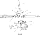
FIG. 2 is an exploded view of the plug valve ofFIG. 1 ; -
FIG. 3 is a schematic structural view of a mounting seat inFIG. 2 ; -
FIG. 4 is a schematic structural view of a valve rod inFIG. 2 ; -
FIG. 5 is a structural schematic view of a transmission gear and a connecting gear inFIG. 2 ; -
FIG. 6 is a structural view of the transmission gear and the connecting gear in another embodiment of the plug valve of the present application. - Description of reference numerals in the figures:
Reference numeral Name Reference numeral Name 10 Plug valve 121 Triggering slot 11 Valve seat 122 Notch 110 Valve body 13 Ignition switch 111 Mounting seat 14 Change-over switch 112 Mounting convex ring 15 Controlling switch 113 Avoidance notch 21 Motor 114 Avoidance hole 22 Transmission gear 115 First limiting groove 221 Gear body 116 Second limiting groove 222 Transmission section 117 First positioning post 223 Meshing tooth 118 Second positioning post 224 Vacant section 119 Supporting portion 23 Connecting gear 12 Valve rod - The realization of the purposes, functional features and advantages of the present application will be further explained with reference to the accompanying drawings in combination with the embodiments.
- In the following, the embodiments of the present application will be clearly and completely described with reference to the drawings in the embodiments of the present application. Obviously, the described embodiments are only some of the embodiments of the present application, and not all of the embodiments. Based on the embodiments of the present application, all other embodiments obtained by those of ordinary skilled in the art without creative efforts shall fall within the claimed scope of the present application.
- It should be noted that all directional indicators (such as up, down, left, right, front, back, etc.) in the embodiments of the present application are only used to explain the relative positional relationship, movement situation, etc. between components in a specific attitude (as shown in the drawings). If the specific attitude changes, the directional indication also changes accordingly.
- In addition, the descriptions related to "first", "second" and the like in the present application are for descriptive purposes only, and should not be understood as indicating or implying their relative importance or implicitly indicating the number of technical features indicated. Therefore, a feature defined by "first" and "second" may explicitly or implicitly include at least one of such feature. In addition, the meaning of "and/or" in the full text includes three parallel solutions, taking "A and/or B" as an example, it includes solution A, solution B, or both solutions A and B. The various embodiments can be combined with each other, but the combination must be based on what can be achieved by those of ordinary skill in the art. When the combination of the embodiments is contradictory or cannot be achieved, it should be considered that such a combination does not exist, or is not within the scope of the claims of the present application.
- The present application provides a plug valve applied in a gas stove.
- In the embodiment of the present application, referring to
FIG. 1 andFIG. 2 , theplug valve 10 includes avalve seat 11, avalve rod 12, a driving mechanism and a change-over switch 14. Thevalve rod 12 is mounted on thevalve seat 11. The driving mechanism is mounted on thevalve seat 11. The driving mechanism is connected to thevalve rod 12 to drive thevalve rod 12. The change-over switch 14 is mounted on thevalve seat 11 and electrically connected to the driving mechanism. Theplug valve 10 has an automatic fire control mode and a manual fire control mode. When the change-over switch 14 is triggered by rotating thevalve rod 12, theplug valve 10 is switched to the automatic fire control mode. - In the present embodiment, the
plug valve 10 further includes a controller. The controller is electrically connected to the change-over switch 14 and the driving mechanism. Theplug valve 10 has a closing gear and a preset firepower gear after rotating a preset angle. When thevalve rod 12 rotates to the preset firepower gear, thevalve rod 12 triggers the change-over switch 14, so that theplug valve 10 is switched to the automatic fire control mode. In the automatic fire control mode, the driving mechanism can be controlled to drive thevalve rod 12 to rotate to adjust the firepower. - In some embodiments, when the
valve rod 12 rotates from the closing gear to the preset firepower gear, ignition is achieved, for example, the ignition process can be completed when thevalve rod 12 rotates away from the closing gear. When thevalve rod 12 is rotated to the preset firepower gear and triggers the change-over switch 14, the controller can detect that the change-over switch 14 is triggered, switch theplug valve 10 to the automatic fire control mode, and then control the driving mechanism to drive thevalve rod 12 to rotate to a target firepower gear according to a preset program, so that the function of automatically adjusting the firepower is achieved. - The
valve rod 12 can be manually adjusted and rotated to the preset firepower gear, or a starting instruction can be sent to the controller through an external terminal, and the controller controls the driving mechanism to rotate thevalve rod 12 to the preset firepower gear. In addition, manual operation can be applied to complete the ignition, or electric control can be applied to complete the ignition. Of course, in other embodiments, theplug valve 10 may not be provided with a controller. - According to the embodiments, the driving mechanism and the change-
over switch 14 are provided on theplug valve 10, and the driving mechanism is connected to thevalve rod 12 to drive thevalve rod 12, so as to rotate thevalve rod 12 through the driving mechanism, so that the automatic fire control mode of adjusting firepower through the driving mechanism rotating thevalve rod 12 is added on the basis of manual fire control mode. thus the user can manually adjust the firepower or select the mode of automatically adjusting the firepower, the selectivity for the user is improved, and the user can conveniently switch and use in multiple cooking modes. - With reference to
FIGS. 2 and3 , in an embodiment, thevalve seat 11 includes avalve body 110 and a mountingseat 111. Thevalve rod 12 is mounted on thevalve body 110. The change-over switch 14 and the driving mechanism are both mounted on the mountingseat 111. Since thevalve body 110 needs to be provided with a gas channel and the like, the structure of thevalve body 110 is relatively complex, by arranging the mountingseat 111 on thevalve body 110 to mount the driving mechanism and the change-over switch 14, the structure of thevalve body 110 is simplified, thevalve body 110 is conveniently manufactured and molded, and the cost of thevalve body 110 is reduced. The mountingseat 111 can be detachably connected to thevalve body 110, for example, the mountingseat 111 can be fixed to thevalve body 110 by means of screws, or the mountingseat 111 can be welded to thevalve body 110, etc. Of course, in other embodiments, the change-over switch 14 and the driving mechanism can be mounted on thevalve body 110. - In one embodiment, the mounting
seat 111 is provided with a mounting hole, and thevalve rod 12 is passed through the mounting hole and mounted on thevalve body 110 through the mounting hole. In some embodiments, the driving mechanism and the change-over switch 14 both need to cooperate with thevalve rod 12, by providing a mounting hole o the mounting seat and passing thevalve rod 12 through the mounting hole, the mounting hole is used as a positioning reference on the mountingseat 111, so that positioning and mounting of the driving mechanism and the change-over switch 14 can be facilitated, and the assembling precision of the driving mechanism and the change-over switch 14 can be improved. Of course, in other embodiments, the mountingseat 111 can be disposed beside thevalve rod 12. - In one embodiment, the mounting
seat 111 is provided with a mountingconvex ring 112 at a periphery of the mounting hole. The mountingconvex ring 112 is annularly sleeved on thevalve rod 12. In some embodiments, the mountingconvex ring 112 is provided on a surface of the mountingseat 111 facing away from thevalve body 110, and thevalve rod 12 partially extends into the mountingconvex ring 112, so that it is equivalent to increasing a length of the mounting hole, which can better limit the deflection of thevalve rod 12 and improve the stability of thevalve rod 12 during rotation. Of course, in other embodiments, it is possible not to provide the mountingconvex ring 112. - In one embodiment, the
plug valve 10 includes anignition switch 13. The mountingconvex ring 112 is provided with anavoidance notch 113. Theignition switch 13 is extended into the mountingconvex ring 112 from theavoidance notch 113 to cooperate with thevalve rod 12. In some embodiments, the mountingconvex ring 112 and the mountingseat 111 are integrally formed, and the avoidingnotch 113 is extended and pierces through an end surface of the mountingconvex ring 112, so that when the mountingseat 111 is formed, the avoidingnotch 113 can be formed at the same time, and the subsequent process of forming theavoidance notch 113 is avoided, to reduce the production cost of the mountingseat 111. Of course, in other embodiments, an avoidance through hole can be provided on the mountingconvex ring 112, and theignition switch 13 is extended into the mountingconvex ring 112 from the avoidance through hole to cooperate with thevalve rod 12. - In one embodiment, the mounting
convex ring 112 is provided with anavoidance hole 114, and the change-over switch 14 is extended into the mountingconvex ring 112 from the avoidinghole 114 to cooperate with thevalve rod 12. In some embodiments, theavoidance hole 114 is spaced from theavoidance notch 113, and theavoidance hole 114 is spaced from the end surface of the mountingconvex ring 112, so that the structure of the mountingconvex ring 112 can be prevented from being reduced, and compared with the manner of providing anotch 122, theavoidance hole 114 has less influence on the structural strength of the mountingconvex ring 112, so that the mountingconvex ring 112 maintains a higher structural strength. Of course, in other embodiments, the mountingconvex ring 112 can be provided with theavoidance notch 122, and the change-over switch 14 is extended into the mountingconvex ring 112 from theavoidance notch 122 to cooperate with thevalve rod 12. - In one embodiment, the
avoidance notch 113 and theavoidance hole 114 are located on two opposite sides of the mountingconvex ring 112. That is, the change-over switch 14 and theignition switch 13 are arranged on the two opposite sides of the mountingconvex ring 112, so that mutual interference between theignition switch 13 and the change-over switch 14 on the mountingseat 111 can be avoided, thevalve rod 12 can be prevented from interfering with theignition switch 13 and the change-over switch 14 respectively, and the reliability of theplug valve 10 is ensured. Of course, in other embodiments, theavoidance notch 113 and theavoidance hole 114 can be provided on the same side of the mountingconvex ring 112, etc. - In one embodiment, the
ignition switch 13 is a microswitch. In some embodiments, theignition switch 13 can be a normally closed microswitch or a normally open microswitch, so that the structure is simple, and the structure of theplug valve 10 is simplified. Of course, in other embodiments, theignition switch 13 can be a photoelectric sensor or a Hall sensor, etc. - Referring to
FIG. 2 to FIG. 4 , in an embodiment, a triggeringgroove 121 is provided around an outer peripheral surface of thevalve rod 12. A pressing portion of theignition switch 13 is extended into the triggeringgroove 121 so that an upper side wall of the triggeringgroove 121 triggers theignition switch 13 when thevalve rod 12 is pressed downwards. Such manner can reduce a radial size of thevalve rod 12, thus reduce an occupied space of thevalve rod 12 and make the structure of theplug valve 10 more compact, as compared with the manner of providing an annular protrusion on the outer peripheral surface of thevalve rod 12 to trigger theignition switch 13. Of course, in other embodiments, the annular protrusion can be provided on the outer peripheral surface of thevalve rod 12 to trigger theignition switch 13. - In one embodiment, the change-
over switch 14 is a microswitch. In some embodiments, the change-over switch 14 can be a normally closed microswitch or a normally open microswitch. Thevalve rod 12 is provided with thenotch 122, a pressing portion of the change-over switch 14 abuts against the outer peripheral surface of thevalve rod 12 when thevalve rod 12 rotates from the closed gear to the preset firepower gear, and makes the change-over switch 14 be in a turn-on state. when thevalve rod 12 is rotated to the preset firepower gear, the pressing portion of the change-over switch 14 is located in thenotch 122 to make the change-over switch 14 switch from the turn-on state to a turn-off state. That is, when thevalve rod 12 is rotated to the preset firepower gear, the state of the change-over switch 14 changes, so that a trigger signal is generated. When the controller detects the trigger signal generated by the change-over switch 14, the automatic fire control mode is started. As such, the structure is simple, and the structure of thevalve rod 12 and the structure of theplug valve 10 can be simplified. Certainly, in other embodiments, a convex portion can be provided on the outer peripheral surface of thevalve rod 12. When thevalve rod 12 is rotated to the preset firepower gear, the change-over switch 14 switches from the turn-off state to the turn-on state. In addition, the change-over switch 14 can be a photoelectric sensor or a Hall sensor, or the like. - The fixing manners of fixing the change-
over switch 14 are various, for example, in one embodiment, the change-over switch 14 is fixed to the mountingseat 111 by means of screws, as such the structure is simple, and the fixing is stable. In other embodiments, an engagement structure can be provided on the mountingseat 111, and the change-over switch 14 is engaged to the mountingseat 111 by the engagement structure. - In one embodiment, the mounting
seat 111 is provided with a first limitinggroove 115, and the change-over switch 14 is arranged in the first limitinggroove 115. In some embodiments, the first limitinggroove 115 can limit the change-over switch 14 to rotate on the mountingseat 111, that is, when the change-over switch 14 is installed in the first limitinggroove 115, the first limitinggroove 115 can preliminarily limit the change-over switch 14, so that the number of screws used for fixing the change-over switch 14 can be reduced, for example, the change-over switch 14 can be stably installed on the mountingseat 111 through one screw cooperating with the first limitinggroove 115. Of course, in other embodiments, the first limitinggroove 115 can be omitted, and the change-over switch 14 is fixed to the mountingseat 111 through at least two screws. - In one embodiment, the mounting
seat 111 is provided with afirst positioning post 117, and the change-over switch 14 is provided with a first positioning hole. When the change-over switch 14 is mounted on the mountingseat 111, thefirst positioning post 117 is inserted in the first positioning hole, so that the change-over switch 14 can be positioned, and the change-over switch 14 can also be prevented to translate on the mountingseat 111. In the embodiment where the first limitinggroove 115 is provided, thefirst positioning post 117 can be disposed in the first limitinggroove 115. - The fixing manners of fixing the
ignition switch 13 are various, for example, in one embodiment, theignition switch 13 is fixed to the mountingseat 111 by screws, as such the structure is simple, and the fixing is stable. In other embodiments, an engagement structure can be provided on the mountingseat 111, and theignition switch 13 is engaged to the mountingseat 111 by the clamping structure. - In one embodiment, the mounting
seat 111 is provided with a second limitinggroove 116, and theignition switch 13 is arranged in the second limitinggroove 116. In some embodiments, the second limitinggroove 116 can limit theignition switch 13 to rotate on the mountingseat 111, that is, when theignition switch 13 is installed in the second limitinggroove 116, the second limitinggroove 116 can preliminarily limit theignition switch 13, so that the number of screws used for fixing theignition switch 13 can be reduced, for example, theignition switch 13 can be stably installed on the mountingseat 111 through a screw cooperating with the second limitinggroove 116. Of course, in other embodiments, the second limitinggroove 116 can be omitted, and theignition switch 13 is fixed to the mountingseat 111 by at least two screws. - In one embodiment, the mounting
seat 111 is provided with asecond positioning post 118, and theignition switch 13 is provided with a second positioning hole. When theignition switch 13 is mounted on the mountingseat 111, thesecond positioning post 118 is inserted in the second positioning hole, so that theignition switch 13 can be positioned, and theignition switch 13 can also be prevented to translate on the mountingseat 111. In the embodiment where the second limitinggroove 116 is provided, thesecond positioning post 118 can be disposed in the second limitinggroove 116. - In one embodiment, the preset firepower gear is the minimum firepower gear. In the embodiment, when the
valve rod 12 rotates from the closing gear to the minimum firepower gear, thevalve rod 12 rotates anticlockwise, and the minimum firepower gear is the maximum angle of rotation of thevalve rod 12. Therefore, when the preset firepower gear is the minimum firepower gear, the user can conveniently determine the position of the preset firepower gear, so that the user can manually rotate thevalve rod 12 to the preset firepower gear. In addition, when the automatic fire control mode is started, themotor 21 may not drive thevalve rod 12 to rotate to the target firepower gear immediately, at this time, if the preset firepower gear is a gear with a larger firepower, the temperature of the cooking utensil can be rapidly increased, and the food in the cooking utensil is burnt. By setting the preset firepower gear to be the minimum firepower gear, the heating speed of the cooking utensil can be slowed down, and the risk that the food in the cooking utensil is burnt due to rapid temperature rise is reduced. Of course, in other embodiments, the preset firepower gear can be another firepower gear. - In one embodiment, the driving mechanism includes a
motor 21 provided on the mountingseat 111, atransmission gear 22 provided on a rotating shaft of themotor 21, and a connectinggear 23 provided on thevalve rod 12. Thetransmission gear 22 is in transmission connection with the connectinggear 23. Therefore, the structure is simple, the transmission is reliable, and the cost of theplug valve 10 can be reduced. Of course, in other embodiments, another transmission mode can be used. - With reference to
FIGS. 1 and2 , in an embodiment, theplug valve 10 further includes a controllingswitch 15, the controller is electrically connected to the controllingswitch 15 and themotor 21, and the controllingswitch 15 is mounted on the mountingseat 111. When themotor 21 drives thetransmission gear 22 to rotate, thetransmission gear 22 intermittently triggers the controllingswitch 15. The controller is configured for calculating a rotation angle of thevalve rod 12 according to the number of times the controllingswitch 15 is triggered. In some embodiments, when the controller controls themotor 21 to drive thetransmission gear 22 to rotate in a first direction, thetransmission gear 22 triggers the controllingswitch 15 one time, and the firepower gear of theplug valve 10 is increased by one gear. When the controller controls themotor 21 to drive thetransmission gear 22 to rotate in a second direction, thetransmission gear 22 triggers the controllingswitch 15 one time, and the firepower gear of theplug valve 10 is reduced by one gear. The first direction is opposite to the second direction. That is, the first direction and the second direction are opposite circumferential directions, and the following description takes the first direction being the anticlockwise direction as an example, but is not limited thereto. When the first direction is the counterclockwise direction, the second direction is the clockwise direction. - In the automatic fire control mode, the controller can control the
motor 21 to drive thetransmission gear 22 to rotate, so that thetransmission gear 22 drives the connectinggear 23 and thevalve rod 12 to rotate. When the controller controls themotor 21 to drive thetransmission gear 22 to rotate in the first direction, thetransmission gear 22 triggers the controllingswitch 15 once, that is, thevalve rod 12 is rotated for a certain angle, so that the firepower gear of theplug valve 10 is increased by one gear. When the controller controls themotor 21 to drive thetransmission gear 22 to rotate in the second direction, thetransmission gear 22 triggers the controllingswitch 15 once, that is, thevalve rod 12 is rotated in the opposite direction for a certain angle, so that the firepower gear of theplug valve 10 is reduced by one gear. Under the driving of themotor 21, thevalve rod 12 rotates to the minimum firepower gear in the second direction, and the controller controls themotor 21 to stop rotating. That is, during the automatic fire control process, thevalve rod 12 rotates between the maximum firepower gear and the minimum firepower gear. Since thetransmission gear 22 cannot be displaced, and the controllingswitch 15 is triggered by the rotation of thetransmission gear 22, the accuracy of detecting the controllingswitch 15 can be ensured, and the accuracy of the automatic fire control mode is ensured. - Therefore, when the controller controls the
motor 21 to drive thetransmission gear 22 to rotate, thetransmission gear 22 can intermittently trigger the controllingswitch 15, and the controller can determine the firepower gear corresponding to the rotation of thevalve rod 12 according to the rotation direction of themotor 21 and the trigger times of the controllingswitch 15. That is, when being used by the user, the controller can control themotor 21 to drive thevalve rod 12 to rotate according to a preset program, so that the firepower of the gas stove can be automatically adjusted. When the user uses the gas stove for cooking, the operation times of operating the gas stove can be reduced and manually adjusting the firepower of the gas stove can be reduce, so that it is more convenient for the user to use the gas stove for cooking, and the convenience of the user using the gas stove is greatly improved. - In addition, if the firepower is determined according to the rotating steps of the
motor 21, for being limited by an operation speed of a single-chip microcomputer, the single-chip microcomputer controls the generation of the stepping pulse of thestep motor 21 by using a timer, for being limited by a time resolution of the timer, the operation speed adjustment of thestep motor 21 is discrete, causing the torques of the speeds to be discrete, furthermore, because of the inertia and the torque, the step-out phenomenon easily occurs. and themotor 21 is difficult to rotate according to a preset number of steps, thus the control precision is poor, and the practicability is poor. Compared with the mode of determining the firepower according to the number of rotating steps of themotor 21, the problem of poor practicability caused by the fact that the steppingmotor 21 is easy to lose steps or cannot rotate according to the preset step number can be avoided, and meanwhile, themotor 21 can be astep motor 21 or be a directcurrent motor 21, the limitation is small, and flexible configuration can be achieved. - According to the embodiments, electric control mechanisms such as the
motor 21, the connectinggear 23 and thetransmission gear 22 can be added on the basis of theconventional plug valve 10, no additional gas pipeline structure is needed, the difficulty of the installation process and the air leakage risk are reduced, and the original installation process and the gas path installation process of the gas stove are not affected. The gas stove of the embodiments is consistent with the commonly used gas stove with a small bottom shell, so that when a user adopts the gas stove of this solution, the installation hole of installating the gas stove does not need to be enlarged, the resistance of the customer to replace the gas stove is reduced, the sale hurdle of the gas stove is reduced, and the market competitiveness is improved. - In one embodiment, the minimum firepower gear corresponds to a position where the
valve rod 12 is rotated anticlockwise for 270 degrees from the closed gear, and the maximum firepower gear of the gas stove corresponds to a position where thevalve rod 12 is rotated anticlockwise for 90 degrees or 180 degrees from the closed gear. In this way, more firepower gears can be arranged between the minimum firepower gear and the maximum firepower gear, and the firepower adjustment precision can be improved. Of course, in other embodiments, the minimum firepower gear and the maximum firepower gear can also correspond to other positions. - With reference to
FIG. 1 ,FIG. 2 andFIG. 5 , in an embodiment, thetransmission gear 22 includes agear body 221, and atransmission tooth section 222 and avacant section 224 which are sequentially arranged in a circumferential direction of thegear body 221, thegear body 221 is connected to a rotating shaft of themotor 21. When in the automatic fire control mode, themotor 21 drives thetransmission gear 22 to rotate, thetransmission tooth section 222 is intermittently engaged with the connectinggear 23. When in the manual fire control mode, thevacant section 224 faces the connectinggear 23. In some embodiments, thetransmission tooth section 222 is provided with meshingteeth 223, so that in the automatic fire control mode, the meshingteeth 223 can meshed with the connectinggear 23 to drive the connectinggear 23 to rotate. The vacant section has no meshingteeth 223. When thevacant section 224 faces the connectinggear 23, the connectinggear 23 is spaced from the meshingteeth 223 of thetransmission tooth section 222, so that thetransmission gear 22 and the connectinggear 23 are independent from each other. That is, in the automatic fire control mode, when thetransmission gear 22 rotates to make thetransmission tooth section 222 mesh with the connectinggear 23, the connectinggear 23 can be driven to rotate, and when thetransmission gear 22 rotates to make thevacant section 224 face the connectinggear 23, thetransmission gear 22 does not drive the connectinggear 23 to rotate. - Therefore, in the automatic fire control mode, when the
transmission gear 22 is driven to rotate continuously by themotor 21, thetransmission tooth section 222 can intermittently mesh with the connectinggear 23 to drive the connectinggear 23 and thevalve rod 12 to rotate, so as to electrically control thevalve rod 12 to rotate to adjust the firepower. In addition, when thetransmission gear 22 is driven by themotor 21 to rotate thevacant section 224 to face the connectinggear 23, themotor 21 is controlled to stop rotating, so that thetransmission gear 22 maintains the state of thevacant section 224 facing the connectinggear 23. When thevalve rod 12 is manually rotated, mutual interference between thetransmission gear 22 and the connectinggear 23 can be avoided, it is ensured that thevalve rod 12 rotates smoothly, and the situation that the torque is increased due to the fact that thetransmission gear 22 is driven to rotate when manually rotatingvalve rod 12 is avoided. Even if themotor 21 is stuck or the power supply is disconnected, the gas stove can still be started by manually rotating thevalve rod 12, and the situation that the gas stove cannot be normally used due to failure or power failure of themotor 21 is avoided. That is, theplug valve 10 in the present solution can automatically adjust the firepower by electrically rotating thevalve rod 12, and can also avoid the situation that the gas stove cannot be normally used due to failure or power failure of themotor 21. Of course, in other embodiments, the controllingswitch 15 can be a photoelectric sensor or a Hall sensor. In addition, thetransmission gear 22 may not be provided with thevacant section 224. - In one embodiment, the controlling
switch 15 is a microswitch and is arranged on the peripheral side of thetransmission gear 22. When themotor 21 drives thetransmission gear 22 to rotate, thetransmission tooth section 222 intermittently triggers the controllingswitch 15, that is, the meshingteeth 223 of thetransmission tooth section 222 can trigger the controllingswitch 15. Therefore, it can avoid that an additional trigger structure is arranged on thetransmission gear 22, thus the structure of thetransmission gear 22 can be simplified, and the assembly processes of theplug valve 10 can be reduced. Of course, in other embodiments, an additional trigger structure for triggering the controllingswitch 15 can be arranged on thetransmission gear 22. At this time, there can be one or more trigger structures on thetransmission gear 22, when there are a plurality of trigger structures, the plurality of trigger structures are distributed at intervals along the circumferential direction of thetransmission gear 22. - Please refer to
FIG. 2 andFIG. 5 , thetransmission gear 22 has a variety of structures. For example, in one embodiment, thetransmission gear 22 includes multipletransmission tooth sections 222 and multiplevacant sections 224, thetransmission tooth sections 222 and thevacant sections 224 are alternately distributed in the circumferential direction of thegear body 221. That is, at least twotransmission tooth sections 222 and at least twovacant sections 224 are provided in thetransmission gear 22, which is equivalent to that a plurality oftransmission tooth sections 222 are arranged on thegear body 221. The plurality oftransmission tooth sections 222 are distributed at intervals along the circumferential direction of thegear body 221, and avacant section 224 is formed between two adjacenttransmission tooth sections 222 along the circumferential direction of thegear body 221. When thevacant section 224 faces the connectinggear 23, the connectinggear 23 is spaced from the meshingteeth 223 of thetransmission tooth sections 222. The number of thetransmission tooth sections 222 can be two, three, four, five or more, or the like. - By arranging a plurality of
transmission tooth sections 222, when thetransmission gear 22 rotates for one circle, the connectinggear 23 and thevalve rod 12 can be driven to rotate multiple times, so that the rotation angle of thevalve rod 12 driven by themotor 21 driving thetransmission gear 22 to rotate for one circle is larger, so that the rotating speed of thevalve rod 12 is larger, and thevalve rod 12 can be rapidly rotated to the target firepower gear. Moreover, it is equivalent to reducing the length of thevacant sections 224 in the circumferential direction of thegear body 221, so that when it is ensured that the connectinggear 23 and thetransmission tooth section 222 do not interfere with each other in the automatic fire control mode, the time occupied by the idle state of the transmission gear 22 (the state that thetransmission tooth sections 222 do not mesh with the connectinggear 23 during the continuous rotation of the transmission gear 22) is reduced. Energy waste in the idle state of thetransmission gear 22 can be reduced, and energy can be saved. In the embodiment of triggering the controllingswitch 15 through the transmission tooth section(s) 222, when thetransmission gear 22 rotates the same angle, a plurality oftransmission tooth sections 22 can increase the number of triggering times of the controllingswitch 15, so that the firepower adjustment is more accurate. In order to ensure the accuracy of controlling the rotation of thevalve rod 12, in one embodiment, the plurality oftransmission tooth sections 222 are uniformly distributed at intervals in the circumferential direction of thegear body 221, and the plurality ofvacant sections 224 are uniformly distributed at intervals in the circumferential direction of thegear body 221. - In another embodiment, the
transmission gear 22 includes onetransmission tooth section 222 and onevacant section 224, that is, thetransmission tooth section 222 and thevacant section 224 are sequentially arranged in the circumferential direction of thegear body 221, so that the structure of thetransmission gear 22 is relatively simple. Arc lengths of thetransmission tooth section 222 and thevacant section 224 in the circumferential direction of thegear body 221 can be the same or different. - In one embodiment, the
transmission tooth section 222 is provided with a plurality of meshingteeth 223, the plurality of meshingteeth 223 are sequentially distributed along the circumferential direction of thegear body 221, and each meshingtooth 223 of the sametransmission tooth section 222 is sequentially meshed with the connectinggear 23. That is, eachtransmission tooth section 222 is provided with at least two meshingteeth 223, when thetransmission gear 22 rotates to make thetransmission tooth section 222 mesh with the connectinggear 23, thetransmission gear 22 rotates the connectinggear 23 and thevalve rod 12 for a larger angle, so that the rotation angle of thevalve rod 12 driven through that themotor 21 drives thetransmission gear 22 to rotate for one circle is larger, the rotating speed of thevalve rod 12 is larger, and thevalve rod 12 can be quickly rotated to the target firepower gear. The number of the meshingteeth 223 of thetransmission tooth section 222 can be two, three, four or more, or the like. - In another embodiment, the
transmission tooth section 222 can be provided with only onemeshing tooth 223, this arrangement can make the structure of thetransmission gear 22 relatively simple. - In one embodiment, the connecting
gear 23 and thetransmission gear 22 are both cylindrical gears. In this embodiment, the connectinggear 23 and thetransmission gear 22 are both straight spur gears, but it's not limited thereto, in other embodiments, the connectinggear 23 and thetransmission gear 22 can be helical spur gears or other types of cylindrical gears. When the connectinggear 23 and thetransmission gear 22 are both cylindrical gears, the structures of the connectinggear 23 and thetransmission gear 22 are relatively simple, which is beneficial to reducing the assembly difficulty and the production cost. - In addition, referring to
FIG. 6 , in another embodiment, both the connectinggear 23 and thetransmission gear 22 are bevel gears. In this embodiment, the connectinggear 23 and thetransmission gear 22 are both straight bevel gears. However, in other embodiments, the connectinggear 23 and thetransmission gear 22 can be helical bevel gears or other types of bevel gears. When the connectinggear 23 and thetransmission gear 22 are both bevel gears, the stability of operations of thetransmission gear 22 and the connectinggear 23 can be ensured, and the noise can be reduced. - Refer to
FIG. 6 , when both the connectinggear 23 and thetransmission gear 22 are bevel gears, in one embodiment, an axis of motor 21 (referring toFIG. 2 ) is parallel to the valve rod 12 (referring toFIG. 2 ). That is, the axis ofmotor 21 and thevalve rod 12 are arranged side by side, and approximately in parallel, so as to reduce the space occupied by themotor 21 in the radial direction of the connectinggear 23, which is conducive to reducing the size of theplug valve 10 in the radial direction of the connectinggear 23, making the structure of theplug valve 10 more compact. - In another embodiment, the axis of the
motor 21 intersects thevalve rod 12. An included angle between an extending direction of the axis of themotor 21 and an extending direction of thevalve rod 12 can be a right angle or an acute angle, with such an arrangement, themotor 21 is installed in the radial direction of the connectinggear 23, so that the occupied space of themotor 21 in a length direction of thevalve rod 12 can be reduced, and the size of theplug valve 10 in the length direction of thevalve rod 12 is reduced. - Referring to
FIG. 5 orFIG. 6 , in an embodiment, a diameter of thetransmission gear 22 is smaller than a diameter of the connectinggear 23. According to the embodiments of the present application, when the rotating speed of themotor 21 is consistent, the rotating speed of the connectinggear 23 is mainly affected by the number of thetransmission tooth sections 222 on thetransmission gear 22 and the number of the meshingteeth 223 on eachtransmission tooth section 222. Therefore, when the number of thetransmission tooth sections 222 on thetransmission gear 22 and the number of the meshingteeth 223 on eachtransmission tooth section 222 meet the transmission requirement, the diameter of thetransmission gear 22 can be set to be smaller than the diameter of the connectinggear 23, so that the occupied space of thetransmission gear 22 can be reduced, and the structural compactness of theplug valve 10 is improved. Of course, in other embodiments, the diameter of thetransmission gear 22 and the diameter of the connectinggear 23 can be substantially the same. In addition, themotor 21 can be provided as aspeed reduction motor 21. - Referring to
FIG. 2 andFIG. 4 , in an embodiment, thevalve rod 12 is movable along its length direction, so as to have an ignition position below. At the ignition position, thevalve rod 12 triggers theignition switch 13. In particular, thevalve rod 12 also has a fire-off position above the ignition position. The ignition position and the fire-off position are two positions when thevalve rod 12 moves along the length direction of thevalve rod 12. When thevalve rod 12 is switched between the ignition position and the fire-off position, thevalve rod 12 does not rotate. At the ignition position, thevalve rod 12 is rotatable. When thevalve rod 12 is at the closing gear, thevalve rod 12 can be switched between the ignition position and the fire-off position. When theplug valve 10 is started for ignition, thevalve rod 12 needs to be pressed down to the ignition position, so that thevalve rod 12 triggers theignition switch 13 to provide an ignition signal to a pulse igniter, so that the pulse igniter is started for ignition. At this time, thevalve rod 12 is manually rotated, so that thevalve rod 12 rotates from the closing gear to a firepower gear, the valve is opened to let the gas get in, so that the gas stove is ignited. - In an embodiment, when the
valve rod 12 is at the fire-off position, the connectinggear 23 and thetransmission gear 22 are spaced from each other in the axial direction of the connecting gear 23 (i.e., the length direction of the valve rod 12). When thevalve rod 12 rotates to a firepower gear, the connectinggear 23 faces thevacant section 224 of thetransmission gear 22, that is, thetransmission tooth section 222 can mesh with the connectinggear 23, at this time, if themotor 21 is started to drive thetransmission gear 22 to rotate, thetransmission tooth section 222 can mesh with the connectinggear 23. When tuning off the fire is needed, thevalve rod 12 is rotated to the closing gear to close the valve, and thevalve rod 12 can move to the fire-off position, so that the connectinggear 23 and thetransmission gear 22 are spaced from each other in the axial direction. Therefore, even if themotor 21 is started when the gas stove is in an off-fire state, themotor 21 and thetransmission gear 22 cannot drive thevalve rod 12 to rotate, so that the reliability and the safety of theplug valve 10 are greatly improved. Of course, in other embodiments, at either the fire-off position or the ignition position, thetransmission tooth section 222 can be engaged with the connectinggear 23. - With reference to
FIGS. 2 to 4 , in an embodiment, the connectinggear 23 is located at one end of the mountingconvex ring 112 on the mountingseat 111 away from thevalve body 110. The mountingseat 111 is also provided with a supportingportion 119 protruded along a protruding direction of the mountingconvex ring 112. Themotor 21 is fixed to one side of the supportingportion 119 facing thevalve body 110. Themotor 21 is passed through the supportingportion 119. Thetransmission gear 22 is located on a surface of the supportingportion 119 away from thevalve body 110 and engages with the connectinggear 23. In this way, thetransmission gear 22 and the connectinggear 23 are substantially in the same plane, which not only ensures that thetransmission gear 22 and the connectinggear 23 can be better engaged, but also reduces the length of the rotating shaft of themotor 21, the possibility of bending and deformation of the rotating shaft of themotor 21 during the rotating of thetransmission gear 22 is reduced, so that the rotating stability of the connectinggear 23 is better. - In one embodiment, the
plug valve 10 further includes a controller and a wireless communication module. The controller is electrically connected to the wireless communication module and the driving mechanism. The wireless communication module is configured for communicating with an external terminal to receive a control instruction from the external terminal, and the controller is configured for controlling the driving mechanism to drive thevalve rod 12 to rotate according to the control instruction. In this way, the wireless communication module is in communication with the external terminal to receive the control instruction from the external terminal. After the controller receives the control instruction of the external terminal through the wireless communication module, the driving mechanism can be controlled to drive thevalve rod 12 to rotate according to the control instruction, so that the firepower of the gas stove can be adjusted or the gas stove is turned off. That is, when the user needs to adjust the firepower of the gas stove or to turn off the gas stove in the cooking process, the user only needs to send a corresponding control instruction to the gas stove through the external terminal, so that the user does not need to enter the kitchen to operate the gas stove. The user can conveniently adjust the firepower and turn off the fire of the gas stove, and the use convenience of the user is improved. Of course, in other embodiments, a control button can be provided on the gas stove, so that thevalve rod 12 can be adjusted through the control button controlling the driving structure, and thevalve rod 12 can also be adjusted through the external terminal controlling the driving structure. - In one embodiment, the wireless communication module is a Bluetooth module, a radio frequency module or a WiFi module. Therefore, the power consumption of the gas stove is low, and the power source can be saved.
- Referring to
FIG. 2 ,FIG. 4 andFIG. 5 , in an embodiment, when the controller receives a fire-off instruction through the wireless communication module or when the cooking program is over and the fire is automatically turned off, the controller controls themotor 21 to drive thevalve rod 12 to rotate. When thevalve rod 12 rotates to the closing gear, thevacant section 224 faces the connectinggear 23, so that when thetransmission gear 22 triggers the controllingswitch 15, thetransmission gear 22 is in a state that thevacant section 224 faces the connectinggear 23. When thevalve rod 12 rotates to the closing gear, thevalve rod 12 can move to the fire-off position. Under the driving of themotor 21, when thevalve rod 12 rotates to the closing gear, thevalve rod 12 triggers the change-over switch 14, so that when thetransmission gear 22 triggers the controllingswitch 15 again, themotor 21 stops rotating. That is, when the controllingswitch 15 is triggered by thetransmission gear 22 to generate the trigger signal, thetransmission gear 22 is located at a position where the meshing of thetransmission tooth section 222 with the connectinggear 23 is ended, and thevacant section 224 faces the connectinggear 23. In other words, when the meshing of thetransmission tooth section 222 with the connectinggear 23 is ended, and the connectinggear 23 faces thevacant section 224, thetransmission gear 22 triggers the controllingswitch 15 to generate the trigger signal. - When a fire-off instruction is sent to the controller through the external terminal or the menu program is over and the fire is automatically turned off, the controller controls the
motor 21 to drive thevalve rod 12 to rotate towards the closing gear. When thevalve rod 12 is rotated to the closing gear, thevalve rod 12 can trigger the change-over switch 14, and at the same time thevalve rod 12 can be automatically switched to the fire-off position, so that the connectinggear 23 and thetransmission gear 22 are spaced from each other in the axial direction of the connectinggear 23. When thevalve rod 12 triggers the change-over switch 14, the controller detects a trigger signal of the change-over switch 14, and takes the trigger signal as one of indication signals for controlling themotor 21 to stop rotating. Only After the controller detects that the change-over switch 14 is triggered by thevalve rod 12 to generate the trigger signal, and the controller further detects that the controllingswitch 15 is triggered by thetransmission gear 22 to generate an electrical signal of a trigger signal, the controller controls themotor 21 to stop rotating. Thus, after the gas stove is turned off, it is ensured that thetransmission gear 22 is in the state of thevacant section 224 facing the connectinggear 23, so as to ensure that thevacant section 224 of thetransmission gear 22 faces the connectinggear 23 when thevalve rod 12 is pressed for ignition next time, to avoid the interference between the connectinggear 23 and thetransmission tooth section 222 on thetransmission gear 22, and improving the reliability of theplug valve 10. Moreover, two functions are realized by using the same change-overswitch 14, the number of switches on theplug valve 10 can be reduced, and the structure of theplug valve 10 is simplified. Of course, in other embodiments, another change-over switch 14 can be provided to provide an indication signal for controlling themotor 21 to stop. In some embodiments, another method can be employed to determine that thevalve rod 12 has rotated to the closing gear, and provide a trigger signal for the controller to control themotor 21 to stop. - When the change-
over switch 14 is a microswitch, thenotch 122 on thevalve rod 12 can be extended in the circumferential direction of thevalve rod 12, and to ensure that when thevalve rod 12 rotates to the preset firepower gear, the pressing portion of the change-over switch 14 is located in thenotch 122, and when thevalve rod 12 rotates to the closing gear, the pressing portion of the change-over switch 14 can also be located in thenotch 122. In some embodiments, twonotches 122 can be provided on thevalve rod 12, when thevalve rod 12 rotates to the preset firepower gear, the pressing portion of the change-over switch 14 is located in one of thenotches 122, and when thevalve rod 12 rotates to the closing gear, the pressing portion of the change-over switch 14 is located in theother notch 122. - Referring to
FIG. 2 andFIG. 5 , in an embodiment, when the change-over switch 14 is a microswitch, thevalve rod 12 is provided with anotch 122, when thevalve rod 12 is located either at the minimum firepower gear or at the closing gear, thevalve rod 12 is located in thenotch 122. When thevalve rod 12 is located between the minimum firepower gear and the closing gear, the pressing portion of the change-over switch 14 abuts against a peripheral surface of thevalve rod 12, and the change-over switch 14 outputs signals when thevalve rod 12 rotates to make the state of the change-over switch 14 changes, and to control themotor 21 to rotate through the controller. In this way, it is possible that only onenotch 122 is provided, so that the machining process of thevalve rod 12 can be reduced, and the structure of thevalve rod 12 can be simplified. - In one embodiment, the
plug valve 10 further includes a controller and a temperature sensor. The controller is electrically connected to the temperature sensor and the driving mechanism, the temperature sensor is configured for detecting a temperature of a cooking utensil, and the controller is further configured for controlling the driving mechanism to drive thevalve rod 12 to rotate according to the temperature. In some embodiments, in the automatic fire control mode, the controller can control the drivingmotor 21 to drive thevalve rod 12 to rotate according to a preset cooking program, so that the firepower of the gas stove can be automatically adjusted. When the automatic ignition mode is started, the temperature of the cooking utensil can be detected in real time through the temperature sensor, so that the controller can control the driving mechanism to drive thevalve rod 12 to the target firepower gear according to the preset program and the temperature, and the precision of the automatic fire control mode of the gas stove can be improved. Of course, in other embodiments, the temperature sensor can be omitted. - The present application further provides a gas stove. The gas stove includes a stove body and a plug valve whose structure can make reference to the above embodiments. For the gas stove adopts all the above embodiments, the gas stove at least has all the beneficial effects brought by the above embodiments, which are not repeated here. The plug valve is arranged on the stove body.
- In this embodiment, the valve rod is protruded out from the stove body, and a knob is arranged at a portion of the valve rod out of the stove body. That is, the user can operate the gas stove manually, or through the external terminal. Compared with that the gas stove can only be operated manually, the user can conveniently adjust the firepower of the gas stove, turn off the fire, and the like. The user can adjust the firepower manually, or select the mode of automatically adjusting the firepower, the options for the user to select are increased, and the user can be conveniently switched between various cooking modes.
Claims (15)
- A plug valve (10) comprising:a valve seat (11);a valve rod (12) mounted on the valve seat (11);a driving mechanism mounted on the valve seat (11) and connected to the valve rod (12) to drive the valve rod (12); wherein the plug valve (10) has an automatic fire control mode and a manual fire control mode, wherein in the automatic fire control mode, the driving mechanism is controlled to drive the valve rod (12) to rotate to adjust the firepower; and wherein in the manual fire control mode, the valve rod (12) is manually adjusted and rotated; andcharacterized in that the plug valve (10) comprisinga change-over switch (14) mounted on the valve seat (11) and electrically connected to the driving mechanism,wherein when the valve rod (12) is rotated to trigger the change-over switch (14), the plug valve (10) is switched to the automatic fire control mode.
- The plug valve (10) of claim 1, wherein the valve seat (11) comprises a valve body (110) and a mounting seat (111), the valve rod (12) being mounted on the valve body (110), and the change-over switch (14) and the driving mechanism both being mounted on the mounting seat (111).
- The plug valve (10) of claim 2, wherein the mounting seat (111) is provided with a mounting hole, and wherein the valve rod (12) extends through the mounting hole to be mounted on the valve body (110).
- The plug valve (10) of claim 3, wherein a mounting convex ring (112) is arranged on a periphery of the mounting hole, and wherein the mounting convex ring (112) is arranged around a periphery of the valve rod (12).
- The plug valve (10) of claim 4, wherein the mounting convex ring (112) is provided with an avoidance hole (114), and wherein the change-over switch (14) extends into the mounting convex ring (112) via the avoidance hole (114) to cooperate with the valve rod (12).
- The plug valve (10) of claim 5, wherein the plug valve (10) comprises an ignition switch (13), wherein the mounting convex ring (112) is provided with an avoidance notch (113), the ignition switch (13) extending into the mounting convex ring (112) via the avoidance notch (113) to cooperate with the valve rod (12).
- The plug valve (10) of claim 6, wherein the avoidance notch (113) and the avoidance hole (114) are distributed on two opposite sides of the mounting convex ring (112); or wherein an outer circumferential ring of the valve rod (12) is provided with a triggering groove (121), the ignition switch (13) is a microswitch, and a pressing portion of the ignition switch (13) extends into the triggering groove (121), the ignition switch (13) is triggered by an upper side wall of the triggering groove (121) in response to the valve rod (12) being pressed downwards; orthe mounting seat (111) is provided with a first limiting groove (115), the change-over switch (14) being arranged in the first limiting groove (115); and optionallythe mounting seat (111) is provided with a second limiting groove (116), the ignition switch (13) being arranged in the second limiting groove (116).
- The plug valve (10) of any one of claims 1 to 7, wherein the driving mechanism comprises a motor (21) arranged on the mounting seat (111), a transmission gear (22) arranged on a rotating shaft of the motor (21) and a connecting gear (23) arranged on the valve rod (12), the transmission gear (22) is in transmission connection with the connecting gear (23).
- The plug valve (10) of claim 8, further comprising a controller and a controlling switch (15), wherein the controller is electrically connected to the controlling switch (15) and the motor (21), the controlling switch (15) being mounted on the mounting seat (111), the controlling switch (15) being intermittently triggered by the transmission gear (22) in response to the motor (21) driving the transmission gear (22) to rotate, and the controller calculating a rotation angle of the valve rod (12) according to times of the controlling switch (15) being triggered.
- The plug valve (10) of claim 9, wherein the transmission gear (22) comprises a gear body (221), a transmission tooth section (222) and a vacant section (224) sequentially arranged in a circumferential direction of the gear body (221), the gear body (221) being connected to the rotating shaft of the motor (21), wherein in the automatic fire control mode, when the motor (21) drives the transmission gear (22) to rotate, the transmission tooth section (222) is intermittently meshed with the connecting gear (23), and wherein in the manual fire control mode, the vacant section (224) faces the connecting gear (23).
- The plug valve (10) of claim 10, wherein the controlling switch (15) is a microswitch arranged on a peripheral side of the transmission gear (22), wherein when the motor (21) drives the transmission gear (22) to rotate, the controlling switch (15) is intermittently triggered by the transmission tooth section (222).
- The plug valve (10) of claim 8, wherein the connecting gear (23) is located at an end of the mounting convex ring (112) on the mounting seat (111) away from the valve body (110), wherein the mounting seat (111) is further provided with a supporting portion (119) along a protruding direction of the mounting convex ring (112), the motor (21) being fixed to a side of the supporting portion (119) facing the valve body (110), and the motor (21) extending through the supporting portion (119), and the transmission gear (22) being located on a surface of the supporting portion (119) back to the valve body (110), and meshed with the connecting gear (23).
- The plug valve (10) of any one of claims 1 to 7 further comprising:a wireless communication module configured for communicating with an external terminal to receive a control instruction from the external terminal; anda controller being electrically connected to the wireless communication module and the driving mechanism, and controlling the driving mechanism to drive the valve rod (12) to rotate according to the control instruction.
- The plug valve (10) of any one of claims 1 to 7 further comprising:a temperature sensor detecting a temperature of a cooking utensil; anda controller being electrically connected to the temperature sensor and the driving mechanism, and controlling the driving mechanism to drive the valve rod (12) to rotate according to the temperature of the cooking utensil.
- A gas stove comprising a stove body and a plug valve (10) of any one of claims 1 to 14, wherein the plug valve (10) is arranged on the stove body.
Applications Claiming Priority (2)
| Application Number | Priority Date | Filing Date | Title |
|---|---|---|---|
| CN202110139459.XA CN112944009B (en) | 2021-02-01 | 2021-02-01 | Plug valve and gas stove |
| PCT/CN2021/087585 WO2022160470A1 (en) | 2021-02-01 | 2021-04-15 | Plug valve and gas stove |
Publications (3)
| Publication Number | Publication Date |
|---|---|
| EP4063735A1 EP4063735A1 (en) | 2022-09-28 |
| EP4063735A4 EP4063735A4 (en) | 2023-01-25 |
| EP4063735B1 true EP4063735B1 (en) | 2024-10-09 |
Family
ID=76241202
Family Applications (1)
| Application Number | Title | Priority Date | Filing Date |
|---|---|---|---|
| EP21881349.1A Active EP4063735B1 (en) | 2021-02-01 | 2021-04-15 | Plug valve and gas stove |
Country Status (3)
| Country | Link |
|---|---|
| EP (1) | EP4063735B1 (en) |
| CN (1) | CN112944009B (en) |
| WO (1) | WO2022160470A1 (en) |
Families Citing this family (4)
| Publication number | Priority date | Publication date | Assignee | Title |
|---|---|---|---|---|
| JP7137451B2 (en) * | 2018-12-03 | 2022-09-14 | 日本電産サンキョー株式会社 | valve drive |
| CN115451348B (en) * | 2022-09-15 | 2023-06-27 | 嵊州市金帝智能厨电有限公司 | Integrated stove for emergency alarm of gas leakage and use method |
| CN116951124B (en) * | 2023-08-24 | 2026-06-05 | 氟络塞尔特种阀门(苏州)有限公司 | A multi-stage plug valve for gas leak detection |
| CN117515587A (en) * | 2023-12-29 | 2024-02-06 | 智慧式有限公司 | An automatically controlled ignition system and method |
Family Cites Families (15)
| Publication number | Priority date | Publication date | Assignee | Title |
|---|---|---|---|---|
| US5094259A (en) * | 1990-05-10 | 1992-03-10 | Hsu Chung Hsiung | Automatic shut-off safety device for gas stove |
| KR20070090702A (en) * | 2006-06-12 | 2007-09-06 | 주식회사 코텍 | Electric ball valve |
| CN201884761U (en) * | 2010-12-08 | 2011-06-29 | 李卫加 | Cock valve with dual-drive mode |
| KR101637091B1 (en) * | 2014-11-19 | 2016-07-20 | 주식회사누리온 | Clutch structure of electronic gas timer |
| CN205227417U (en) * | 2015-12-09 | 2016-05-11 | 蒋爱国 | Do benefit to drive arrangement of automatic control gas firepower |
| CN205560864U (en) * | 2016-03-03 | 2016-09-07 | 宁波来特燃气具有限公司 | Can open two micro -gap switch's gas valve simultaneously |
| CN106338092B (en) * | 2016-11-18 | 2019-09-03 | 佛山市人百金贸易有限公司 | A kind of gas-cooker regulating device and gas-cooker |
| CN106931469B (en) * | 2017-03-01 | 2023-07-14 | 浙江苏泊尔家电制造有限公司 | Gas hobs and how they work |
| CN107888465B (en) * | 2017-11-14 | 2020-04-07 | 珠海格力电器股份有限公司 | Gas stove and control device thereof |
| CN208431814U (en) * | 2018-06-11 | 2019-01-25 | 广东万家乐厨房科技有限公司 | Gas-cooker automatic timing unit and gas-cooker |
| CN109268523B (en) * | 2018-11-14 | 2023-08-15 | 佛山市顺德区美的洗涤电器制造有限公司 | Gas stopcock |
| CN111237502A (en) * | 2020-02-26 | 2020-06-05 | 华帝股份有限公司 | Valve body structure with automatic firepower switching function |
| CN111237524B (en) * | 2020-03-11 | 2025-01-03 | 广东重尚美物联科技有限公司 | A manual and automatic valve |
| CN111396586B (en) * | 2020-04-10 | 2022-02-25 | 佛山市顺德区美的洗涤电器制造有限公司 | Plug Valves and Household Appliances |
| CN111946850B (en) * | 2020-08-28 | 2024-12-03 | 广东万家乐燃气具有限公司 | Stopcock and gas stove |
-
2021
- 2021-02-01 CN CN202110139459.XA patent/CN112944009B/en active Active
- 2021-04-15 EP EP21881349.1A patent/EP4063735B1/en active Active
- 2021-04-15 WO PCT/CN2021/087585 patent/WO2022160470A1/en not_active Ceased
Also Published As
| Publication number | Publication date |
|---|---|
| CN112944009A (en) | 2021-06-11 |
| CN112944009B (en) | 2023-05-26 |
| WO2022160470A1 (en) | 2022-08-04 |
| EP4063735A1 (en) | 2022-09-28 |
| EP4063735A4 (en) | 2023-01-25 |
Similar Documents
| Publication | Publication Date | Title |
|---|---|---|
| EP4063735A1 (en) | Plug valve and gas stove | |
| CN112728593B (en) | Gas stove and control method thereof and computer-readable storage medium | |
| CA2292105C (en) | Single knob rotary oven control apparatus providing continuous and discrete control information | |
| ES2755084T3 (en) | Control device for gas taps | |
| CN112728592B (en) | Plug valve and gas stove | |
| EP4033509B1 (en) | Operating assembly and household appliance | |
| US11971737B2 (en) | Toaster oven with tactile feedback control | |
| US20120152708A1 (en) | Appliance Timer | |
| JP2001221656A (en) | Motor actuator | |
| US6992258B2 (en) | Switching device for gas operated appliance | |
| CN115076399B (en) | Gas plug valve | |
| CN212157282U (en) | Gas stove control valve capable of displaying firepower gear and gas stove thereof | |
| CN112542359A (en) | Circuit breaker | |
| CN119103571A (en) | Gas stove timer and control method thereof | |
| KR101180679B1 (en) | Double dial knob of heater control for vehicle | |
| CN115435139B (en) | Flow regulating valve, household appliance control method, and household appliance | |
| JP4425753B2 (en) | Engine operation unit | |
| CN223845454U (en) | Knob lifting structure and electric kettle base | |
| CN118856075A (en) | Gas valve, gas stove and gas stove control method | |
| CN220103200U (en) | Fire force regulating and controlling device for gas range | |
| CN223005021U (en) | Gas stove timer | |
| CN223108752U (en) | A knob and gas stove with digital display and timing control | |
| CN220435476U (en) | Gear hand feeling adjusting device and plug valve of gas stove | |
| CN222968134U (en) | Hand controller and electric lifting table with same | |
| CN222670087U (en) | Knob device and gas stove |
Legal Events
| Date | Code | Title | Description |
|---|---|---|---|
| STAA | Information on the status of an ep patent application or granted ep patent |
Free format text: STATUS: UNKNOWN |
|
| STAA | Information on the status of an ep patent application or granted ep patent |
Free format text: STATUS: THE INTERNATIONAL PUBLICATION HAS BEEN MADE |
|
| PUAI | Public reference made under article 153(3) epc to a published international application that has entered the european phase |
Free format text: ORIGINAL CODE: 0009012 |
|
| STAA | Information on the status of an ep patent application or granted ep patent |
Free format text: STATUS: REQUEST FOR EXAMINATION WAS MADE |
|
| 17P | Request for examination filed |
Effective date: 20220427 |
|
| AK | Designated contracting states |
Kind code of ref document: A1 Designated state(s): AL AT BE BG CH CY CZ DE DK EE ES FI FR GB GR HR HU IE IS IT LI LT LU LV MC MK MT NL NO PL PT RO RS SE SI SK SM TR |
|
| A4 | Supplementary search report drawn up and despatched |
Effective date: 20221222 |
|
| RIC1 | Information provided on ipc code assigned before grant |
Ipc: F23K 5/00 20060101ALI20221216BHEP Ipc: F23K 5/14 20060101ALI20221216BHEP Ipc: F16K 5/02 20060101ALI20221216BHEP Ipc: F24C 3/10 20060101AFI20221216BHEP |
|
| DAV | Request for validation of the european patent (deleted) | ||
| DAX | Request for extension of the european patent (deleted) | ||
| GRAP | Despatch of communication of intention to grant a patent |
Free format text: ORIGINAL CODE: EPIDOSNIGR1 |
|
| STAA | Information on the status of an ep patent application or granted ep patent |
Free format text: STATUS: GRANT OF PATENT IS INTENDED |
|
| RIC1 | Information provided on ipc code assigned before grant |
Ipc: F23K 5/00 20060101ALI20240710BHEP Ipc: F23K 5/14 20060101ALI20240710BHEP Ipc: F16K 5/02 20060101ALI20240710BHEP Ipc: F24C 3/10 20060101AFI20240710BHEP |
|
| INTG | Intention to grant announced |
Effective date: 20240730 |
|
| GRAS | Grant fee paid |
Free format text: ORIGINAL CODE: EPIDOSNIGR3 |
|
| GRAA | (expected) grant |
Free format text: ORIGINAL CODE: 0009210 |
|
| STAA | Information on the status of an ep patent application or granted ep patent |
Free format text: STATUS: THE PATENT HAS BEEN GRANTED |
|
| AK | Designated contracting states |
Kind code of ref document: B1 Designated state(s): AL AT BE BG CH CY CZ DE DK EE ES FI FR GB GR HR HU IE IS IT LI LT LU LV MC MK MT NL NO PL PT RO RS SE SI SK SM TR |
|
| REG | Reference to a national code |
Ref country code: CH Ref legal event code: EP |
|
| REG | Reference to a national code |
Ref country code: DE Ref legal event code: R096 Ref document number: 602021020171 Country of ref document: DE |
|
| REG | Reference to a national code |
Ref country code: IE Ref legal event code: FG4D |
|
| REG | Reference to a national code |
Ref country code: LT Ref legal event code: MG9D |
|
| REG | Reference to a national code |
Ref country code: NL Ref legal event code: MP Effective date: 20241009 |
|
| REG | Reference to a national code |
Ref country code: AT Ref legal event code: MK05 Ref document number: 1730955 Country of ref document: AT Kind code of ref document: T Effective date: 20241009 |
|
| PG25 | Lapsed in a contracting state [announced via postgrant information from national office to epo] |
Ref country code: NL Free format text: LAPSE BECAUSE OF FAILURE TO SUBMIT A TRANSLATION OF THE DESCRIPTION OR TO PAY THE FEE WITHIN THE PRESCRIBED TIME-LIMIT Effective date: 20241009 |
|
| PG25 | Lapsed in a contracting state [announced via postgrant information from national office to epo] |
Ref country code: NL Free format text: LAPSE BECAUSE OF FAILURE TO SUBMIT A TRANSLATION OF THE DESCRIPTION OR TO PAY THE FEE WITHIN THE PRESCRIBED TIME-LIMIT Effective date: 20241009 |
|
| PG25 | Lapsed in a contracting state [announced via postgrant information from national office to epo] |
Ref country code: PT Free format text: LAPSE BECAUSE OF FAILURE TO SUBMIT A TRANSLATION OF THE DESCRIPTION OR TO PAY THE FEE WITHIN THE PRESCRIBED TIME-LIMIT Effective date: 20250210 Ref country code: HR Free format text: LAPSE BECAUSE OF FAILURE TO SUBMIT A TRANSLATION OF THE DESCRIPTION OR TO PAY THE FEE WITHIN THE PRESCRIBED TIME-LIMIT Effective date: 20241009 Ref country code: IS Free format text: LAPSE BECAUSE OF FAILURE TO SUBMIT A TRANSLATION OF THE DESCRIPTION OR TO PAY THE FEE WITHIN THE PRESCRIBED TIME-LIMIT Effective date: 20250209 |
|
| PG25 | Lapsed in a contracting state [announced via postgrant information from national office to epo] |
Ref country code: FI Free format text: LAPSE BECAUSE OF FAILURE TO SUBMIT A TRANSLATION OF THE DESCRIPTION OR TO PAY THE FEE WITHIN THE PRESCRIBED TIME-LIMIT Effective date: 20241009 |
|
| PG25 | Lapsed in a contracting state [announced via postgrant information from national office to epo] |
Ref country code: BG Free format text: LAPSE BECAUSE OF FAILURE TO SUBMIT A TRANSLATION OF THE DESCRIPTION OR TO PAY THE FEE WITHIN THE PRESCRIBED TIME-LIMIT Effective date: 20241009 |
|
| PG25 | Lapsed in a contracting state [announced via postgrant information from national office to epo] |
Ref country code: ES Free format text: LAPSE BECAUSE OF FAILURE TO SUBMIT A TRANSLATION OF THE DESCRIPTION OR TO PAY THE FEE WITHIN THE PRESCRIBED TIME-LIMIT Effective date: 20241009 |
|
| PG25 | Lapsed in a contracting state [announced via postgrant information from national office to epo] |
Ref country code: NO Free format text: LAPSE BECAUSE OF FAILURE TO SUBMIT A TRANSLATION OF THE DESCRIPTION OR TO PAY THE FEE WITHIN THE PRESCRIBED TIME-LIMIT Effective date: 20250109 |
|
| PG25 | Lapsed in a contracting state [announced via postgrant information from national office to epo] |
Ref country code: LV Free format text: LAPSE BECAUSE OF FAILURE TO SUBMIT A TRANSLATION OF THE DESCRIPTION OR TO PAY THE FEE WITHIN THE PRESCRIBED TIME-LIMIT Effective date: 20241009 Ref country code: AT Free format text: LAPSE BECAUSE OF FAILURE TO SUBMIT A TRANSLATION OF THE DESCRIPTION OR TO PAY THE FEE WITHIN THE PRESCRIBED TIME-LIMIT Effective date: 20241009 Ref country code: GR Free format text: LAPSE BECAUSE OF FAILURE TO SUBMIT A TRANSLATION OF THE DESCRIPTION OR TO PAY THE FEE WITHIN THE PRESCRIBED TIME-LIMIT Effective date: 20250110 |
|
| PG25 | Lapsed in a contracting state [announced via postgrant information from national office to epo] |
Ref country code: PL Free format text: LAPSE BECAUSE OF FAILURE TO SUBMIT A TRANSLATION OF THE DESCRIPTION OR TO PAY THE FEE WITHIN THE PRESCRIBED TIME-LIMIT Effective date: 20241009 |
|
| PG25 | Lapsed in a contracting state [announced via postgrant information from national office to epo] |
Ref country code: RS Free format text: LAPSE BECAUSE OF FAILURE TO SUBMIT A TRANSLATION OF THE DESCRIPTION OR TO PAY THE FEE WITHIN THE PRESCRIBED TIME-LIMIT Effective date: 20250109 |
|
| PG25 | Lapsed in a contracting state [announced via postgrant information from national office to epo] |
Ref country code: SM Free format text: LAPSE BECAUSE OF FAILURE TO SUBMIT A TRANSLATION OF THE DESCRIPTION OR TO PAY THE FEE WITHIN THE PRESCRIBED TIME-LIMIT Effective date: 20241009 |
|
| PG25 | Lapsed in a contracting state [announced via postgrant information from national office to epo] |
Ref country code: DK Free format text: LAPSE BECAUSE OF FAILURE TO SUBMIT A TRANSLATION OF THE DESCRIPTION OR TO PAY THE FEE WITHIN THE PRESCRIBED TIME-LIMIT Effective date: 20241009 |
|
| REG | Reference to a national code |
Ref country code: DE Ref legal event code: R097 Ref document number: 602021020171 Country of ref document: DE |
|
| PG25 | Lapsed in a contracting state [announced via postgrant information from national office to epo] |
Ref country code: EE Free format text: LAPSE BECAUSE OF FAILURE TO SUBMIT A TRANSLATION OF THE DESCRIPTION OR TO PAY THE FEE WITHIN THE PRESCRIBED TIME-LIMIT Effective date: 20241009 |
|
| PG25 | Lapsed in a contracting state [announced via postgrant information from national office to epo] |
Ref country code: RO Free format text: LAPSE BECAUSE OF FAILURE TO SUBMIT A TRANSLATION OF THE DESCRIPTION OR TO PAY THE FEE WITHIN THE PRESCRIBED TIME-LIMIT Effective date: 20241009 |
|
| PG25 | Lapsed in a contracting state [announced via postgrant information from national office to epo] |
Ref country code: SK Free format text: LAPSE BECAUSE OF FAILURE TO SUBMIT A TRANSLATION OF THE DESCRIPTION OR TO PAY THE FEE WITHIN THE PRESCRIBED TIME-LIMIT Effective date: 20241009 |
|
| PG25 | Lapsed in a contracting state [announced via postgrant information from national office to epo] |
Ref country code: CZ Free format text: LAPSE BECAUSE OF FAILURE TO SUBMIT A TRANSLATION OF THE DESCRIPTION OR TO PAY THE FEE WITHIN THE PRESCRIBED TIME-LIMIT Effective date: 20241009 |
|
| PLBE | No opposition filed within time limit |
Free format text: ORIGINAL CODE: 0009261 |
|
| STAA | Information on the status of an ep patent application or granted ep patent |
Free format text: STATUS: NO OPPOSITION FILED WITHIN TIME LIMIT |
|
| PG25 | Lapsed in a contracting state [announced via postgrant information from national office to epo] |
Ref country code: SE Free format text: LAPSE BECAUSE OF FAILURE TO SUBMIT A TRANSLATION OF THE DESCRIPTION OR TO PAY THE FEE WITHIN THE PRESCRIBED TIME-LIMIT Effective date: 20241009 |
|
| 26N | No opposition filed |
Effective date: 20250710 |
|
| REG | Reference to a national code |
Ref country code: CH Ref legal event code: H13 Free format text: ST27 STATUS EVENT CODE: U-0-0-H10-H13 (AS PROVIDED BY THE NATIONAL OFFICE) Effective date: 20251125 |
|
| PG25 | Lapsed in a contracting state [announced via postgrant information from national office to epo] |
Ref country code: LU Free format text: LAPSE BECAUSE OF NON-PAYMENT OF DUE FEES Effective date: 20250415 |
|
| PG25 | Lapsed in a contracting state [announced via postgrant information from national office to epo] |
Ref country code: MC Free format text: LAPSE BECAUSE OF FAILURE TO SUBMIT A TRANSLATION OF THE DESCRIPTION OR TO PAY THE FEE WITHIN THE PRESCRIBED TIME-LIMIT Effective date: 20241009 |
|
| REG | Reference to a national code |
Ref country code: BE Ref legal event code: MM Effective date: 20250430 |
|
| PG25 | Lapsed in a contracting state [announced via postgrant information from national office to epo] |
Ref country code: BE Free format text: LAPSE BECAUSE OF NON-PAYMENT OF DUE FEES Effective date: 20250430 |
|
| PG25 | Lapsed in a contracting state [announced via postgrant information from national office to epo] |
Ref country code: CH Free format text: LAPSE BECAUSE OF NON-PAYMENT OF DUE FEES Effective date: 20250430 |
|
| PGFP | Annual fee paid to national office [announced via postgrant information from national office to epo] |
Ref country code: GB Payment date: 20260327 Year of fee payment: 6 |
|
| PG25 | Lapsed in a contracting state [announced via postgrant information from national office to epo] |
Ref country code: IE Free format text: LAPSE BECAUSE OF NON-PAYMENT OF DUE FEES Effective date: 20250415 |
|
| PG25 | Lapsed in a contracting state [announced via postgrant information from national office to epo] |
Ref country code: CY Free format text: LAPSE BECAUSE OF FAILURE TO SUBMIT A TRANSLATION OF THE DESCRIPTION OR TO PAY THE FEE WITHIN THE PRESCRIBED TIME-LIMIT Effective date: 20241009 |
|
| PG25 | Lapsed in a contracting state [announced via postgrant information from national office to epo] |
Ref country code: LT Free format text: LAPSE BECAUSE OF FAILURE TO SUBMIT A TRANSLATION OF THE DESCRIPTION OR TO PAY THE FEE WITHIN THE PRESCRIBED TIME-LIMIT Effective date: 20241009 |
|
| PGFP | Annual fee paid to national office [announced via postgrant information from national office to epo] |
Ref country code: IT Payment date: 20260423 Year of fee payment: 6 |
|
| PGFP | Annual fee paid to national office [announced via postgrant information from national office to epo] |
Ref country code: DE Payment date: 20260427 Year of fee payment: 6 |
|
| PGFP | Annual fee paid to national office [announced via postgrant information from national office to epo] |
Ref country code: FR Payment date: 20260422 Year of fee payment: 6 |