EP4063697A1 - Electronic parking brake mechanism - Google Patents
Electronic parking brake mechanism Download PDFInfo
- Publication number
- EP4063697A1 EP4063697A1 EP20907683.5A EP20907683A EP4063697A1 EP 4063697 A1 EP4063697 A1 EP 4063697A1 EP 20907683 A EP20907683 A EP 20907683A EP 4063697 A1 EP4063697 A1 EP 4063697A1
- Authority
- EP
- European Patent Office
- Prior art keywords
- parking
- pawl
- cam
- guide shaft
- assembly
- Prior art date
- Legal status (The legal status is an assumption and is not a legal conclusion. Google has not performed a legal analysis and makes no representation as to the accuracy of the status listed.)
- Granted
Links
Images


Classifications
-
- F—MECHANICAL ENGINEERING; LIGHTING; HEATING; WEAPONS; BLASTING
- F16—ENGINEERING ELEMENTS AND UNITS; GENERAL MEASURES FOR PRODUCING AND MAINTAINING EFFECTIVE FUNCTIONING OF MACHINES OR INSTALLATIONS; THERMAL INSULATION IN GENERAL
- F16H—GEARING
- F16H63/00—Control outputs from the control unit to change-speed- or reversing-gearings for conveying rotary motion or to other devices than the final output mechanism
- F16H63/02—Final output mechanisms therefor; Actuating means for the final output mechanisms
- F16H63/30—Constructional features of the final output mechanisms
- F16H63/34—Locking or disabling mechanisms
- F16H63/3416—Parking lock mechanisms or brakes in the transmission
- F16H63/3425—Parking lock mechanisms or brakes in the transmission characterised by pawls or wheels
- F16H63/3433—Details of latch mechanisms, e.g. for keeping pawls out of engagement
-
- F—MECHANICAL ENGINEERING; LIGHTING; HEATING; WEAPONS; BLASTING
- F16—ENGINEERING ELEMENTS AND UNITS; GENERAL MEASURES FOR PRODUCING AND MAINTAINING EFFECTIVE FUNCTIONING OF MACHINES OR INSTALLATIONS; THERMAL INSULATION IN GENERAL
- F16H—GEARING
- F16H63/00—Control outputs from the control unit to change-speed- or reversing-gearings for conveying rotary motion or to other devices than the final output mechanism
- F16H63/02—Final output mechanisms therefor; Actuating means for the final output mechanisms
- F16H63/30—Constructional features of the final output mechanisms
- F16H63/34—Locking or disabling mechanisms
- F16H63/3416—Parking lock mechanisms or brakes in the transmission
- F16H63/3425—Parking lock mechanisms or brakes in the transmission characterised by pawls or wheels
-
- B—PERFORMING OPERATIONS; TRANSPORTING
- B60—VEHICLES IN GENERAL
- B60T—VEHICLE BRAKE CONTROL SYSTEMS OR PARTS THEREOF; BRAKE CONTROL SYSTEMS OR PARTS THEREOF, IN GENERAL; ARRANGEMENT OF BRAKING ELEMENTS ON VEHICLES IN GENERAL; PORTABLE DEVICES FOR PREVENTING UNWANTED MOVEMENT OF VEHICLES; VEHICLE MODIFICATIONS TO FACILITATE COOLING OF BRAKES
- B60T1/00—Arrangements of braking elements, i.e. of those parts where braking effect occurs specially for vehicles
- B60T1/005—Arrangements of braking elements, i.e. of those parts where braking effect occurs specially for vehicles by locking of wheel or transmission rotation
-
- F—MECHANICAL ENGINEERING; LIGHTING; HEATING; WEAPONS; BLASTING
- F16—ENGINEERING ELEMENTS AND UNITS; GENERAL MEASURES FOR PRODUCING AND MAINTAINING EFFECTIVE FUNCTIONING OF MACHINES OR INSTALLATIONS; THERMAL INSULATION IN GENERAL
- F16D—COUPLINGS FOR TRANSMITTING ROTATION; CLUTCHES; BRAKES
- F16D63/00—Brakes not otherwise provided for; Brakes combining more than one of the types of groups F16D49/00 - F16D61/00
- F16D63/006—Positive locking brakes
-
- F—MECHANICAL ENGINEERING; LIGHTING; HEATING; WEAPONS; BLASTING
- F16—ENGINEERING ELEMENTS AND UNITS; GENERAL MEASURES FOR PRODUCING AND MAINTAINING EFFECTIVE FUNCTIONING OF MACHINES OR INSTALLATIONS; THERMAL INSULATION IN GENERAL
- F16H—GEARING
- F16H63/00—Control outputs from the control unit to change-speed- or reversing-gearings for conveying rotary motion or to other devices than the final output mechanism
- F16H63/02—Final output mechanisms therefor; Actuating means for the final output mechanisms
- F16H63/30—Constructional features of the final output mechanisms
- F16H63/304—Constructional features of the final output mechanisms the final output mechanisms comprising elements moved by electrical or magnetic force
-
- F—MECHANICAL ENGINEERING; LIGHTING; HEATING; WEAPONS; BLASTING
- F16—ENGINEERING ELEMENTS AND UNITS; GENERAL MEASURES FOR PRODUCING AND MAINTAINING EFFECTIVE FUNCTIONING OF MACHINES OR INSTALLATIONS; THERMAL INSULATION IN GENERAL
- F16H—GEARING
- F16H63/00—Control outputs from the control unit to change-speed- or reversing-gearings for conveying rotary motion or to other devices than the final output mechanism
- F16H63/02—Final output mechanisms therefor; Actuating means for the final output mechanisms
- F16H63/30—Constructional features of the final output mechanisms
- F16H63/34—Locking or disabling mechanisms
- F16H63/3416—Parking lock mechanisms or brakes in the transmission
- F16H63/3458—Parking lock mechanisms or brakes in the transmission with electric actuating means, e.g. shift by wire
- F16H63/3466—Parking lock mechanisms or brakes in the transmission with electric actuating means, e.g. shift by wire using electric motors
-
- F—MECHANICAL ENGINEERING; LIGHTING; HEATING; WEAPONS; BLASTING
- F16—ENGINEERING ELEMENTS AND UNITS; GENERAL MEASURES FOR PRODUCING AND MAINTAINING EFFECTIVE FUNCTIONING OF MACHINES OR INSTALLATIONS; THERMAL INSULATION IN GENERAL
- F16H—GEARING
- F16H63/00—Control outputs from the control unit to change-speed- or reversing-gearings for conveying rotary motion or to other devices than the final output mechanism
- F16H63/02—Final output mechanisms therefor; Actuating means for the final output mechanisms
- F16H63/30—Constructional features of the final output mechanisms
- F16H63/34—Locking or disabling mechanisms
- F16H63/3416—Parking lock mechanisms or brakes in the transmission
- F16H63/3491—Emergency release or engagement of parking locks or brakes
-
- F—MECHANICAL ENGINEERING; LIGHTING; HEATING; WEAPONS; BLASTING
- F16—ENGINEERING ELEMENTS AND UNITS; GENERAL MEASURES FOR PRODUCING AND MAINTAINING EFFECTIVE FUNCTIONING OF MACHINES OR INSTALLATIONS; THERMAL INSULATION IN GENERAL
- F16H—GEARING
- F16H63/00—Control outputs from the control unit to change-speed- or reversing-gearings for conveying rotary motion or to other devices than the final output mechanism
- F16H63/02—Final output mechanisms therefor; Actuating means for the final output mechanisms
- F16H63/30—Constructional features of the final output mechanisms
- F16H63/304—Constructional features of the final output mechanisms the final output mechanisms comprising elements moved by electrical or magnetic force
- F16H2063/3056—Constructional features of the final output mechanisms the final output mechanisms comprising elements moved by electrical or magnetic force using cam or crank gearing
Definitions
- the present disclosure relates to the field of parking control, in particular to an electronic parking mechanism.
- the electronic parking mechanism of gearbox is a mechanism for preventing the vehicle from sliding forward or backward when the vehicle is parked on a road or a ramp.
- most electronic parking mechanisms of gearbox in new energy vehicles have insufficient structural flexibility and short service life.
- the mechanical unlocking mechanism is provided at the worm of the parking motor; when the parking motor is powered off, this unlocking method requires the driver to operate under the vehicle to perform mechanical unlocking, and thus has low safety and poor comfort.
- the present disclosure provides an electronic parking mechanism to solve or partially solve the above problems.
- the present disclosure provides an electronic parking mechanism, comprising a parking cam assembly, a pawl assembly and a parking gear;
- the pawl assembly As the parking cam rotates, the pawl assembly is in a first position where the pawl assembly parks in the parking gear and a second position where the pawl assembly parks out the parking gear, respectively.
- the parking gear is non-rotatable or rotatable depending on whether the pawl assembly is in the first position or the second position.
- a protrusion of the parking cam is provided with a circumferential contour extending along an axial direction of the parking guide shaft, the arc protrusion is provided on an outer side of the circumferential contour, and the parking cam assembly further comprises an axial limit block and a parking cam limit plate; the parking cam limit plate is fixed on the parking guide shaft, the axial limit block is sleeved on the parking guide shaft with an interference fit, the parking cam is sleeved on the parking guide shaft between the axial limit block and the parking cam limit plate, and the parking cam limit plate can drive the parking cam to rotate.
- the parking cam limit plate comprises at least a first blade and a second blade spaced apart from each other, the first blade and the second blade are respectively provided on two sides of the protrusion;
- the parking guide shaft comprises a flat part on one end thereof and a circular part on the other end thereof, the parking guide shaft runs through casings of a gearbox, the flat part of the parking guide shaft is connected with a parking motor, and the parking motor drives the parking guide shaft to rotate.
- the parking cam assembly further comprises a thrust bearing, the thrust bearing is sleeved on the parking guide shaft, and an outer edge of the thrust bearing is fixed on a left-side casing of the gearbox with an interference fit.
- the pawl assembly further comprises a roller, a roller pin and a torsion spring
- the electronic parking mechanism further comprises a mechanical unlocking device, the mechanical unlocking device comprises an elastic member and an actuator, and the actuator drives the parking guide shaft to move along an axial direction so that the parking cam and the upper part of the pawl are respectively butted against the arc protrusion or the parking cam is at a side of the arc protrusion in the axial direction.
- the actuator is a pull wire or pull rod, one end of the pull wire or pull rod is connected to one end of the parking guide shaft, the other end of the pull wire or pull rod is connected to a controller in the cab, and the pull rod or pull rod provides an axial force for an axial movement of the parking guide shaft.
- the elastic member is a spring kit
- the spring kit is provided between the parking cam assembly and a right-side casing of the gearbox, and the elastic member is preset with a preload when being installed.
- a guide groove for accommodating the parking guide shaft is provided on an inner side of the right-side casing of the gearbox, and a sealing ring for sealing the parking guide shaft is provided in the guide groove.
- the above electronic parking mechanism has the following advantages: Through the specific structure of the parking cam assembly and pawl assembly, the connection of the electronic parking mechanism and the flexibility of the driving process are ensured, thereby increasing the operability and service life of the electronic parking mechanism.
- the electronic parking mechanism can provide the emergency mechanical unlocking function when the parking motor is powered off.
- the parking guide shaft is connected with the pull rod or pull wire outside the gearbox, so that the driver can realize the mechanical unlocking in the cab. Because the electronic parking mechanism can realize the pure mechanical unlocking without power supply in the cab, the driver does not need to get off the vehicle for operation, and thus it has high safety and good operation comfort.
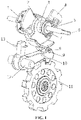
- FIG. 1 is a schematic view of the structure of an electronic parking mechanism according to an embodiment of the present disclosure
- FIG. 2 is a schematic sectional view of the electronic parking mechanism in a parking-in state according to an embodiment of the present disclosure
- FIG. 3 shows a schematic sectional view of the electronic parking mechanism after mechanical unlocking according to an embodiment of the present disclosure
- FIG. 4 is a schematic view of the structure of a parking cam and a pawl in a parking-in state according to an embodiment of the present disclosure
- FIG. 5 is a schematic view of the structure of a parking cam and a pawl after mechanical unlocking according to an embodiment of the present disclosure.
- an embodiment of the present disclosure proposes an electronic parking mechanism, which comprises a parking cam assembly, a pawl assembly and a parking gear 11.
- the parking cam assembly comprises a parking guide shaft 6 and a parking cam 2.
- the parking cam 2 is sleeved on the parking guide shaft 6.
- One side of the parking cam 2 is provided with an arc protrusion along the circumferential direction.
- the pawl assembly is controlled to be in a first position where the pawl assembly parks in the parking gear 11 and a second position where the pawl assembly parks out the parking gear 11.
- the pawl assembly comprises a pawl 10 and a pawl shaft 12.
- the upper part of the pawl 10 can contact the parking cam 2.
- the pawl shaft 12 is provided on one side of the pawl 10, and the pawl 10 can rotate around the pawl shaft 12.
- the parking gear 11 With the rotation of the parking cam 2 and the rotation of the pawl 10 around the pawl shaft 12, the parking gear 11 is in two states, namely, the non-rotatable state or the rotatable state, respectively, so as to realize parking or driving.
- the parking guide shaft 6 rotates and drives the parking cam 2 to rotate.
- the arc protrusion presses the pawl assembly downward to make it in the first position where the pawl assembly parks in the parking gear 11; and when the arc protrusion is separated from the pawl assembly, the pawl assembly is separated from the parking gear 11 and is in the second position where the pawl assembly parks out the parking gear 11, thereby realizing the flexible parking of the vehicle and obtaining a better parking effect.
- the protrusion of the parking cam 2 is provided with a circumferential contour extending along an axial direction of the parking guide shaft 6, and the arc protrusion is provided on an outer side of the circumferential contour.
- the circumferential contour on the parking cam 2 contacts the parking pawl assembly, the parking pawl assembly is in the second position where the pawl assembly parks out the parking gear 11, the circumferential contour serves to define the position of the parking pawl assembly and makes the parking pawl assembly move within a certain range.
- the parking cam assembly also comprises an axial limit block 3 and a parking cam limit plate 4.
- the parking cam limit plate 4 is fixed on the parking guide shaft 6, the axial limit block 3 is sleeved on the parking guide shaft 6 with an interference fit, the parking cam 2 is sleeved on the parking guide shaft 6 between the axial limit block 3 and the parking cam limit plate 4, and the parking cam limit plate 4 can drive the parking cam 2 to rotate.
- the axial limit block 3 defines the position of the parking cam 2, and the parking cam 2 can rotate flexibly on the parking guide shaft 6 between the axial limit block 3 and the parking cam limit plate 4.
- the parking cam limit plate 4 comprises at least a first blade and a second blade spaced apart from each other, the first blade and the second blade are respectively provided on two sides of the protrusion; a side of the first blade facing the protrusion is provided with a first spring column, the protrusion is provided with a corresponding second spring column, and a spring 5 is sleeved on the first spring column and the second spring column; and the second blade is formed with a curved claw, and the curved claw can butt against the other side of the protrusion.
- the curved claw on the parking limit plate 4 butts against the parking cam 2 to drive the parking cam 2 to rotate counterclockwise.
- the arc protrusion is separated from the pawl assembly
- the circumferential contour is in contact with the pawl assembly
- the pawl assembly is separated from the parking gear 11 to realize the parking-out operation.
- the parking guide shaft 6 comprises a flat part on one end thereof and a circular part on the other end thereof.
- the parking guide shaft 6 runs through the casings of the gearbox.
- the flat part of the parking guide shaft 6 is connected with a parking motor, and the parking motor drives the parking guide shaft 6 to rotate.
- the setting of the flat part in this embodiment facilitates the connection and driving of the parking motor.
- the flat part is not necessary, and any structure that can realize the detachable connection with the parking motor is within the protection scope of the present disclosure.
- the parking cam assembly further comprises a thrust bearing 7, the thrust bearing 7 is sleeved on the parking guide shaft 6, and an outer edge of the thrust bearing 7 is fixed on a left-side casing 16 of the gearbox with an interference fit.
- the setting of the thrust bearing 7 ensures that the parking cam assembly can rotate flexibly.
- the pawl assembly further comprises a roller 8, a roller pin 9 and a torsion spring 13.
- the upper part of the pawl 10 is provided with a groove
- the roller 8 is fixed in the groove through the roller pin 9
- the roller 8 can be in contact with the parking cam 2
- the lower part of the pawl 10 is provided with a boss which can engage with the parking gear 11.
- the pawl 10 When the electronic parking mechanism is in the parking state, the pawl 10 is pressed downward by the parking cam 2 so that the boss at the lower part of the pawl 10 engages with the parking gear 11 to realize parking-in.
- One side of the pawl 10 is sleeved on the pawl shaft 12, the pawl shaft 12 is fixed on the casings on both sides of the gearbox, and the pawl 10 can rotate around the pawl shaft 12.
- One end of the torsion spring 13 is fixed on the casings of the gearbox, and the other end is fixed on the pawl 10.
- the torsion spring 13 has a certain preload when being installed. The preload always raises the pawl 10 upward, so that the pawl 10 is pre-pressed against the parking cam 2.
- the roller 8 can roll around the roller pin 9 to reduce the friction between the parking cam 2 and the pawl 10.
- the roller 8 contacts the circumferential contour or arc protrusion on the parking cam 2.
- the electronic parking mechanism further comprises a mechanical unlocking device, the mechanical unlocking device comprises an elastic member 1 and an actuator.
- the actuator is connected with the circular part of the parking guide shaft 6.
- the actuator drives the parking guide shaft 6 to move along an axial direction so that the upper part of the pawl 10 are respectively butted against the arc protrusion or a side of the parking cam 2 in the axial direction of the arc protrusion.
- the actuator can drive the parking guide shaft 6 to move axially, and then drive the parking cam 2 to move axially, so that the arc protrusion on the parking cam 2 is separated from the roller 8, the circumferential contour is in contact with the roller 8, the pawl 10 will be raised up under the force of the torsion spring 13, and the boss at the lower part of the pawl 10 is separated from the parking gear 11 to realize the parking-out, thereby ensuring that the parking mechanism can be unlocked when the vehicle has no power.
- the position relationship between the parking cam 2 and the pawl 10 after mechanical unlocking is shown in FIG. 5 .
- the upper part of the pawl 10 when the parking gear 11 is in the fixed state of parking-in, the upper part of the pawl 10 butts against the arc protrusion on the circumferential contour of the parking cam 2; when the parking motor works normally, the upper part of the pawl 10 butts against the circumferential contour on the side of the arc protrusion in the circumferential direction; after unlocking by the mechanical unlocking device, the upper part of the pawl 10 butts against the circumferential contour on the side of the arc protrusion in the axial direction.
- the actuator is a pull wire or pull rod
- one end of the pull wire or pull rod is connected to one end of the parking guide shaft 6, and the other end of the pull wire or pull rod is connected to a controller in the cab.
- the pull rod or pull rod provides an axial force for the axial movement of the parking guide shaft 6 to make the parking guide shaft 6 move axially in the direction of the end of the circular part.
- the other end of the pull wire or pull rod is provided in the cab, so that it is convenient for the driver to unlock the parking mechanism in the cab through the pull wire or pull rod.
- the elastic member 1 is a spring kit. As shown in FIG. 2 and FIG. 3 , the spring kit is provided between the parking cam assembly and the right-side casing 15 of the gearbox, and the elastic member 1 is preset with a preload when being installed. Due to the preload, the elastic member 1 is in close proximity to the right-side casing 15 of the gearbox.
- the parking cam assembly moves axially in the direction of the end of the circular part of the parking guide shaft 6, and the elastic member 1 is further pressed toward the right-side casing 15 of the gearbox.
- a cylindrical protrusion is provided on the inner side of the right-side casing 15 of the gearbox, which includes a guide groove for accommodating the parking guide shaft 6, and a sealing ring 14 for sealing the parking guide shaft 6 is provided in the guide groove.
- the circular part of the parking guide shaft 6 can move axially in the guide groove to realize mechanical unlocking.
- the sealing ring 14 is provided at the contact part between the guide groove and the parking guide shaft 6 to seal and prevent dust from entering the gearbox.
- an electronic parking mechanism which comprises a parking cam assembly, a pawl assembly and a parking gear
- the parking cam assembly comprises a parking guide shaft and a parking cam, the parking cam is sleeved on the parking guide shaft, and one side of the parking cam is provided with an arc protrusion along a circumferential direction so that as the parking cam rotates, the pawl assembly is in a first position where the pawl assembly parks in the parking gear and a second position where the pawl assembly parks out the parking gear, respectively
- the pawl assembly comprises a pawl and a pawl shaft, an upper part of the pawl can contact the parking cam, the pawl shaft is provided on a side of the pawl, and the pawl can rotate around the pawl shaft.
- the electronic parking mechanism can realize flexible contact and driving. It provides the emergency mechanical unlocking function when the parking motor is powered off.
- the parking guide shaft is connected with the pull rod or pull wire outside the gearbox, which can realize the mechanical unlocking by the driver in the cab.
- the electronic parking mechanism can realize the pure mechanical unlocking without power supply in the cab, and it does not need the driver to get off the vehicle for operation, and thus it has high safety and good operation comfort.
Landscapes
- Engineering & Computer Science (AREA)
- General Engineering & Computer Science (AREA)
- Mechanical Engineering (AREA)
- Transportation (AREA)
- Gear-Shifting Mechanisms (AREA)
Abstract
Description
- The present disclosure relates to the field of parking control, in particular to an electronic parking mechanism.
- The electronic parking mechanism of gearbox is a mechanism for preventing the vehicle from sliding forward or backward when the vehicle is parked on a road or a ramp. At present, most electronic parking mechanisms of gearbox in new energy vehicles have insufficient structural flexibility and short service life. Moreover, the mechanical unlocking mechanism is provided at the worm of the parking motor; when the parking motor is powered off, this unlocking method requires the driver to operate under the vehicle to perform mechanical unlocking, and thus has low safety and poor comfort.
- In view of the above problems, the present disclosure provides an electronic parking mechanism to solve or partially solve the above problems.
- In order to achieve the above object, the present disclosure adopts the following technical solutions.
- The present disclosure provides an electronic parking mechanism, comprising a parking cam assembly, a pawl assembly and a parking gear;
- the parking cam assembly comprises a parking guide shaft and a parking cam, the parking cam is sleeved on the parking guide shaft, and one side of the parking cam is provided with an arc protrusion along a circumferential direction;
- the pawl assembly comprises a pawl and a pawl shaft, an upper part of the pawl can contact the side of the parking cam which is provided with the arc protrusion, the pawl shaft is provided on a side of the pawl, and the pawl can rotate around the pawl shaft;
- As the parking cam rotates, the pawl assembly is in a first position where the pawl assembly parks in the parking gear and a second position where the pawl assembly parks out the parking gear, respectively. The parking gear is non-rotatable or rotatable depending on whether the pawl assembly is in the first position or the second position.
- Further, a protrusion of the parking cam is provided with a circumferential contour extending along an axial direction of the parking guide shaft, the arc protrusion is provided on an outer side of the circumferential contour, and the parking cam assembly further comprises an axial limit block and a parking cam limit plate;
the parking cam limit plate is fixed on the parking guide shaft, the axial limit block is sleeved on the parking guide shaft with an interference fit, the parking cam is sleeved on the parking guide shaft between the axial limit block and the parking cam limit plate, and the parking cam limit plate can drive the parking cam to rotate. - Further, the parking cam limit plate comprises at least a first blade and a second blade spaced apart from each other, the first blade and the second blade are respectively provided on two sides of the protrusion;
- a side of the first blade facing the protrusion is provided with a first spring column, the protrusion is provided with a corresponding second spring column, and a spring is sleeved on the first spring column and the second spring column; and
- the second blade is formed with a curved claw, and the curved claw can butt against the other side of the protrusion.
- Further, the parking guide shaft comprises a flat part on one end thereof and a circular part on the other end thereof, the parking guide shaft runs through casings of a gearbox, the flat part of the parking guide shaft is connected with a parking motor, and the parking motor drives the parking guide shaft to rotate.
- Further, the parking cam assembly further comprises a thrust bearing, the thrust bearing is sleeved on the parking guide shaft, and an outer edge of the thrust bearing is fixed on a left-side casing of the gearbox with an interference fit.
- Further, the pawl assembly further comprises a roller, a roller pin and a torsion spring;
- an upper part of the pawl is provided with a groove, the roller is fixed in the groove through the roller pin, the roller can be in contact with the parking cam, and a lower part of the pawl is provided with a boss which can engage with the parking gear;
- one side of the pawl is sleeved on the pawl shaft, the pawl shaft is fixed on casings on both sides of the gearbox, and the pawl can rotate around the pawl shaft;
- one end of the torsion spring is fixed on the casings of the gearbox, and the other end of the torsion spring is fixed on the pawl, so that the pawl is pre-pressed against the parking cam.
- Further, the electronic parking mechanism further comprises a mechanical unlocking device, the mechanical unlocking device comprises an elastic member and an actuator, and the actuator drives the parking guide shaft to move along an axial direction so that the parking cam and the upper part of the pawl are respectively butted against the arc protrusion or the parking cam is at a side of the arc protrusion in the axial direction.
- Further, the actuator is a pull wire or pull rod, one end of the pull wire or pull rod is connected to one end of the parking guide shaft, the other end of the pull wire or pull rod is connected to a controller in the cab, and the pull rod or pull rod provides an axial force for an axial movement of the parking guide shaft.
- Further, the elastic member is a spring kit, the spring kit is provided between the parking cam assembly and a right-side casing of the gearbox, and the elastic member is preset with a preload when being installed.
- Further, a guide groove for accommodating the parking guide shaft is provided on an inner side of the right-side casing of the gearbox, and a sealing ring for sealing the parking guide shaft is provided in the guide groove.
- The above electronic parking mechanism has the following advantages:
Through the specific structure of the parking cam assembly and pawl assembly, the connection of the electronic parking mechanism and the flexibility of the driving process are ensured, thereby increasing the operability and service life of the electronic parking mechanism. - Moreover, the electronic parking mechanism can provide the emergency mechanical unlocking function when the parking motor is powered off. The parking guide shaft is connected with the pull rod or pull wire outside the gearbox, so that the driver can realize the mechanical unlocking in the cab. Because the electronic parking mechanism can realize the pure mechanical unlocking without power supply in the cab, the driver does not need to get off the vehicle for operation, and thus it has high safety and good operation comfort.
- The above is only an overview of the technical solutions of the present disclosure. In order to better understand the technical means of the present disclosure so that it can be implemented according to the contents of the description, and in order to make the above and other objects, features and advantages of the present disclosure more obvious and easy to understand, the specific embodiments of the present disclosure are given below.
- By reading the detailed description of the preferred embodiments below, various other advantages and benefits will become clear to a person of ordinary skill in the art. The drawings are only used for the purpose of illustrating the preferred embodiments, and should not be considered as a limitation to the present disclosure. Moreover, throughout the drawings, like reference numerals denote like components. In the drawings:
-
FIG. 1 is a schematic view of the structure of an electronic parking mechanism according to an embodiment of the present disclosure; -
FIG. 2 is a schematic sectional view of the electronic parking mechanism in a parking-in state according to an embodiment of the present disclosure; -
FIG. 3 shows a schematic sectional view of the electronic parking mechanism after mechanical unlocking according to an embodiment of the present disclosure; -
FIG. 4 is a schematic view of the structure of a parking cam and a pawl in a parking-in state according to an embodiment of the present disclosure; and -
FIG. 5 is a schematic view of the structure of a parking cam and a pawl after mechanical unlocking according to an embodiment of the present disclosure. - In the drawings: 1. elastic member, 2. parking cam, 3. axial limit block, 4. parking cam limit plate, 5. spring, 6. parking guide shaft, 7. thrust bearing, 8. roller, 9. roller pin, 10. pawl, 11. parking gear, 12. pawl shaft, 13. torsion spring, 14. sealing ring, 15. Right casing of the gearbox, 16. Left casing of the gearbox.
- Illustrative embodiments of the present disclosure will be described in more detail with reference to the drawings. Although the drawings show the illustrative embodiments of the present disclosure, it should be understood that the present disclosure can be implemented in various ways and should not be limited by the embodiments disclosed herein. On the contrary, the embodiments are provided for a more thorough and complete understanding of the present disclosure, so as to fully convey the scope of the present disclosure to those skilled in the art.
-
FIG. 1 is a schematic view of the structure of an electronic parking mechanism according to an embodiment of the present disclosure;FIG. 2 is a schematic sectional view of the electronic parking mechanism in a parking-in state according to an embodiment of the present disclosure;FIG. 3 shows a schematic sectional view of the electronic parking mechanism after mechanical unlocking according to an embodiment of the present disclosure;FIG. 4 is a schematic view of the structure of a parking cam and a pawl in a parking-in state according to an embodiment of the present disclosure; andFIG. 5 is a schematic view of the structure of a parking cam and a pawl after mechanical unlocking according to an embodiment of the present disclosure. - As shown in
FIG. 1 , an embodiment of the present disclosure proposes an electronic parking mechanism, which comprises a parking cam assembly, a pawl assembly and aparking gear 11. - The parking cam assembly comprises a
parking guide shaft 6 and aparking cam 2. Theparking cam 2 is sleeved on theparking guide shaft 6. One side of theparking cam 2 is provided with an arc protrusion along the circumferential direction. Depending on whether the pawl assembly butts against the arc protrusion on theparking cam 2 as theparking cam 2 rotates, the pawl assembly is controlled to be in a first position where the pawl assembly parks in theparking gear 11 and a second position where the pawl assembly parks out theparking gear 11. - The pawl assembly comprises a
pawl 10 and apawl shaft 12. The upper part of thepawl 10 can contact theparking cam 2. Thepawl shaft 12 is provided on one side of thepawl 10, and thepawl 10 can rotate around thepawl shaft 12. - With the rotation of the
parking cam 2 and the rotation of thepawl 10 around thepawl shaft 12, theparking gear 11 is in two states, namely, the non-rotatable state or the rotatable state, respectively, so as to realize parking or driving. - In sum, in the embodiment of the present disclosure, the
parking guide shaft 6 rotates and drives theparking cam 2 to rotate. When the arc protrusion provided on theparking cam 2 contacts the pawl assembly, the arc protrusion presses the pawl assembly downward to make it in the first position where the pawl assembly parks in theparking gear 11; and when the arc protrusion is separated from the pawl assembly, the pawl assembly is separated from theparking gear 11 and is in the second position where the pawl assembly parks out theparking gear 11, thereby realizing the flexible parking of the vehicle and obtaining a better parking effect. - In an embodiment, the protrusion of the
parking cam 2 is provided with a circumferential contour extending along an axial direction of theparking guide shaft 6, and the arc protrusion is provided on an outer side of the circumferential contour. When the circumferential contour on theparking cam 2 contacts the parking pawl assembly, the parking pawl assembly is in the second position where the pawl assembly parks out theparking gear 11, the circumferential contour serves to define the position of the parking pawl assembly and makes the parking pawl assembly move within a certain range. The parking cam assembly also comprises anaxial limit block 3 and a parkingcam limit plate 4. - The parking
cam limit plate 4 is fixed on theparking guide shaft 6, theaxial limit block 3 is sleeved on theparking guide shaft 6 with an interference fit, theparking cam 2 is sleeved on theparking guide shaft 6 between theaxial limit block 3 and the parkingcam limit plate 4, and the parkingcam limit plate 4 can drive theparking cam 2 to rotate. Theaxial limit block 3 defines the position of theparking cam 2, and theparking cam 2 can rotate flexibly on theparking guide shaft 6 between theaxial limit block 3 and the parkingcam limit plate 4. - In an embodiment, as shown in
FIG. 1 , the parkingcam limit plate 4 comprises at least a first blade and a second blade spaced apart from each other, the first blade and the second blade are respectively provided on two sides of the protrusion; a side of the first blade facing the protrusion is provided with a first spring column, the protrusion is provided with a corresponding second spring column, and aspring 5 is sleeved on the first spring column and the second spring column; and the second blade is formed with a curved claw, and the curved claw can butt against the other side of the protrusion. When the parking state is changed from parking-in to parking-out, theparking guide shaft 6 rotates counterclockwise to drive theparking limit plate 4 to rotate counterclockwise. The curved claw on theparking limit plate 4 butts against theparking cam 2 to drive theparking cam 2 to rotate counterclockwise. At this point, the arc protrusion is separated from the pawl assembly, the circumferential contour is in contact with the pawl assembly, and the pawl assembly is separated from theparking gear 11 to realize the parking-out operation. When the parking state is changed from parking-out to parking-in, theparking guide shaft 6 rotates clockwise to drive theparking limit plate 4 to rotate clockwise. The first spring column on theparking limit plate 4 presses thespring 5 downward, and drives theparking cam 2 to rotate clockwise due to the action of thespring 5. At this point, the circumferential contour is separated from the pawl assembly, the arc protrusion contacts the pawl assembly, and presses the pawl assembly downward to engage with theparking gear 11, thereby realizing the parking-in operation. The position relationship between theparking cam 2 and thepawl 10 in the parking-in state is shown inFIG. 4 . - In an embodiment, the
parking guide shaft 6 comprises a flat part on one end thereof and a circular part on the other end thereof. Theparking guide shaft 6 runs through the casings of the gearbox. The flat part of theparking guide shaft 6 is connected with a parking motor, and the parking motor drives theparking guide shaft 6 to rotate. The setting of the flat part in this embodiment facilitates the connection and driving of the parking motor. Of course, the flat part is not necessary, and any structure that can realize the detachable connection with the parking motor is within the protection scope of the present disclosure. - In an embodiment, the parking cam assembly further comprises a
thrust bearing 7, thethrust bearing 7 is sleeved on theparking guide shaft 6, and an outer edge of thethrust bearing 7 is fixed on a left-side casing 16 of the gearbox with an interference fit. The setting of thethrust bearing 7 ensures that the parking cam assembly can rotate flexibly. - In an embodiment, as shown in
FIG. 1 , the pawl assembly further comprises aroller 8, aroller pin 9 and atorsion spring 13. - In order to improve the connection reliability between the
pawl 10 and theparking cam 2, reduce the friction and wear of the joint part between the upper part of thepawl 10 and theparking cam 2, and improve its service life, the upper part of thepawl 10 is provided with a groove, theroller 8 is fixed in the groove through theroller pin 9, theroller 8 can be in contact with theparking cam 2, and the lower part of thepawl 10 is provided with a boss which can engage with theparking gear 11. - When the electronic parking mechanism is in the parking state, the
pawl 10 is pressed downward by theparking cam 2 so that the boss at the lower part of thepawl 10 engages with theparking gear 11 to realize parking-in. One side of thepawl 10 is sleeved on thepawl shaft 12, thepawl shaft 12 is fixed on the casings on both sides of the gearbox, and thepawl 10 can rotate around thepawl shaft 12. One end of thetorsion spring 13 is fixed on the casings of the gearbox, and the other end is fixed on thepawl 10. Thetorsion spring 13 has a certain preload when being installed. The preload always raises thepawl 10 upward, so that thepawl 10 is pre-pressed against theparking cam 2. Theroller 8 can roll around theroller pin 9 to reduce the friction between theparking cam 2 and thepawl 10. Theroller 8 contacts the circumferential contour or arc protrusion on theparking cam 2. - In an embodiment, the electronic parking mechanism further comprises a mechanical unlocking device, the mechanical unlocking device comprises an
elastic member 1 and an actuator. The actuator is connected with the circular part of theparking guide shaft 6. The actuator drives theparking guide shaft 6 to move along an axial direction so that the upper part of thepawl 10 are respectively butted against the arc protrusion or a side of theparking cam 2 in the axial direction of the arc protrusion. - When the parking motor is powered off and the electronic parking mechanism is in the parking state, the actuator can drive the
parking guide shaft 6 to move axially, and then drive theparking cam 2 to move axially, so that the arc protrusion on theparking cam 2 is separated from theroller 8, the circumferential contour is in contact with theroller 8, thepawl 10 will be raised up under the force of thetorsion spring 13, and the boss at the lower part of thepawl 10 is separated from theparking gear 11 to realize the parking-out, thereby ensuring that the parking mechanism can be unlocked when the vehicle has no power. The position relationship between theparking cam 2 and thepawl 10 after mechanical unlocking is shown inFIG. 5 . - Therefore, depending on the butting relationship between the
pawl 10 and the circumferential contour of theparking cam 2, when theparking gear 11 is in the fixed state of parking-in, the upper part of thepawl 10 butts against the arc protrusion on the circumferential contour of theparking cam 2; when the parking motor works normally, the upper part of thepawl 10 butts against the circumferential contour on the side of the arc protrusion in the circumferential direction; after unlocking by the mechanical unlocking device, the upper part of thepawl 10 butts against the circumferential contour on the side of the arc protrusion in the axial direction. - In an embodiment, the actuator is a pull wire or pull rod, one end of the pull wire or pull rod is connected to one end of the
parking guide shaft 6, and the other end of the pull wire or pull rod is connected to a controller in the cab. The pull rod or pull rod provides an axial force for the axial movement of theparking guide shaft 6 to make theparking guide shaft 6 move axially in the direction of the end of the circular part. The other end of the pull wire or pull rod is provided in the cab, so that it is convenient for the driver to unlock the parking mechanism in the cab through the pull wire or pull rod. - In an embodiment, the
elastic member 1 is a spring kit. As shown inFIG. 2 and FIG. 3 , the spring kit is provided between the parking cam assembly and the right-side casing 15 of the gearbox, and theelastic member 1 is preset with a preload when being installed. Due to the preload, theelastic member 1 is in close proximity to the right-side casing 15 of the gearbox. When the electronic parking mechanism is mechanically unlocked, the parking cam assembly moves axially in the direction of the end of the circular part of theparking guide shaft 6, and theelastic member 1 is further pressed toward the right-side casing 15 of the gearbox. - In an embodiment, as shown in
FIG. 2 and FIG. 3 , a cylindrical protrusion is provided on the inner side of the right-side casing 15 of the gearbox, which includes a guide groove for accommodating theparking guide shaft 6, and a sealingring 14 for sealing theparking guide shaft 6 is provided in the guide groove. The circular part of theparking guide shaft 6 can move axially in the guide groove to realize mechanical unlocking. The sealingring 14 is provided at the contact part between the guide groove and theparking guide shaft 6 to seal and prevent dust from entering the gearbox. - In sum, the present disclosure provides an electronic parking mechanism, which comprises a parking cam assembly, a pawl assembly and a parking gear; the parking cam assembly comprises a parking guide shaft and a parking cam, the parking cam is sleeved on the parking guide shaft, and one side of the parking cam is provided with an arc protrusion along a circumferential direction so that as the parking cam rotates, the pawl assembly is in a first position where the pawl assembly parks in the parking gear and a second position where the pawl assembly parks out the parking gear, respectively; the pawl assembly comprises a pawl and a pawl shaft, an upper part of the pawl can contact the parking cam, the pawl shaft is provided on a side of the pawl, and the pawl can rotate around the pawl shaft. The electronic parking mechanism according to the present disclosure can realize flexible contact and driving. It provides the emergency mechanical unlocking function when the parking motor is powered off. The parking guide shaft is connected with the pull rod or pull wire outside the gearbox, which can realize the mechanical unlocking by the driver in the cab. The electronic parking mechanism can realize the pure mechanical unlocking without power supply in the cab, and it does not need the driver to get off the vehicle for operation, and thus it has high safety and good operation comfort.
- The above are only the specific embodiments of the present disclosure, and the protection scope of the present disclosure is not limited to this. Any person skilled in the art can easily think of changes or substitutions within the technical scope disclosed by the present disclosure, which should be covered by the protection scope of the present disclosure.
- In the description provided herein, a large number of specific details are described. However, it can be understood that embodiments of the present disclosure can be practiced without these specific details. In some embodiments, well-known methods, structures and techniques are not shown in detail so as not to obscure the understanding of this specification.
Claims (10)
- An electronic parking mechanism, characterized by comprising: a parking cam assembly, a pawl assembly and a parking gear (11);the parking cam assembly comprises a parking guide shaft (6) and a parking cam (2), the parking cam (2) is sleeved on the parking guide shaft (6), and one side of the parking cam (2) is provided with an arc protrusion along a circumferential direction;the pawl assembly comprises a pawl (10) and a pawl shaft (12), an upper part of the pawl (10) can contact the side of the parking cam (2) which is provided with the arc protrusion, the pawl shaft (12) is provided on a side of the pawl (10), and the pawl (10) can rotate around the pawl shaft (12); andas the parking cam (2) rotates, the pawl assembly is in a first position where the pawl assembly parks in the parking gear (11) and a second position where the pawl assembly parks out the parking gear (11), respectively, and the parking gear (11) is non-rotatable or rotatable.
- The electronic parking mechanism according to claim 1, characterized in that: a protrusion of the parking cam (2) is provided with a circumferential contour extending along an axial direction of the parking guide shaft (6), the arc protrusion is provided on an outer side of the circumferential contour, and the parking cam assembly further comprises an axial limit block (3) and a parking cam limit plate (4);
the parking cam limit plate (4) is fixed on the parking guide shaft (6), the axial limit block (3) is sleeved on the parking guide shaft (6) with an interference fit, the parking cam (2) is sleeved on the parking guide shaft (6) between the axial limit block (3) and the parking cam limit plate (4), and the parking cam limit plate (4) can drive the parking cam (2) to rotate. - The electronic parking mechanism according to claim 2, characterized in that: the parking cam limit plate (4) comprises at least a first blade and a second blade spaced apart from each other, the first blade and the second blade are respectively provided on two sides of the protrusion;a side of the first blade facing the protrusion is provided with a first spring column, the protrusion is provided with a corresponding second spring column, and a spring (5) is sleeved on the first spring column and the second spring column; andthe second blade is formed with a curved claw, and the curved claw can butt against the other side of the protrusion.
- The electronic parking mechanism according to claim 2, characterized in that: the parking guide shaft (6) comprises a flat part on one end thereof and a circular part on the other end thereof, the parking guide shaft (6) runs through casings of a gearbox, the flat part of the parking guide shaft (6) is connected with a parking motor, and the parking motor drives the parking guide shaft (6) to rotate.
- The electronic parking mechanism according to claim 2, characterized in that: the parking cam assembly further comprises a thrust bearing (7), the thrust bearing (7) is sleeved on the parking guide shaft (6), and an outer edge of the thrust bearing (7) is fixed on a left-side casing of the gearbox with an interference fit.
- The electronic parking mechanism according to claim 1, characterized in that: the pawl assembly further comprises a roller (8), a roller pin (9) and a torsion spring (13);an upper part of the pawl (10) is provided with a groove, the roller (8) is fixed in the groove through the roller pin (9), the roller (8) can be in contact with the parking cam (2), and a lower part of the pawl (10) is provided with a boss which can engage with the parking gear (11);one side of the pawl (10) is sleeved on the pawl shaft (12), the pawl shaft (12) is fixed on casings on both sides of the gearbox, and the pawl (10) can rotate around the pawl shaft (12); andone end of the torsion spring (13) is fixed on the casings of the gearbox, and the other end of the torsion spring (13) is fixed on the pawl (10), so that the pawl (10) is pre-pressed against the parking cam (2).
- The electronic parking mechanism according to any one of claims 1-6, further characterized by comprising: a mechanical unlocking device, the mechanical unlocking device comprises an elastic member (1) and an actuator, and the actuator drives the parking guide shaft (6) to move along an axial direction so that the parking cam (2) and an upper part of the pawl (10) are respectively butted against the arc protrusion or the parking cam (2) is at a side of the arc protrusion in the axial direction.
- The electronic parking mechanism according to claim 7, characterized in that: the actuator is a pull wire or pull rod, one end of the pull wire or pull rod is connected to one end of the parking guide shaft (6), the other end of the pull wire or pull rod is connected to a controller in the cab, and the pull wire or pull rod provides an axial force for axial movement of the parking guide shaft (6).
- The electronic parking mechanism according to claim 7, characterized in that: the elastic member (1) is a spring kit, the spring kit is provided between the parking cam assembly and a right-side casing of the gearbox, and the elastic member (1) is preset with a preload when being installed.
- The electronic parking mechanism according to claim 9, characterized in that: a guide groove for accommodating the parking guide shaft (6) is provided on an inner side of the right-side casing of the gearbox, and a sealing ring (14) for sealing the parking guide shaft (6) is provided in the guide groove.
Applications Claiming Priority (2)
| Application Number | Priority Date | Filing Date | Title |
|---|---|---|---|
| CN201911364191.9A CN110953341B (en) | 2019-12-26 | 2019-12-26 | Electronic parking mechanism |
| PCT/CN2020/071267 WO2021128494A1 (en) | 2019-12-26 | 2020-01-10 | Electronic parking brake mechanism |
Publications (3)
| Publication Number | Publication Date |
|---|---|
| EP4063697A1 true EP4063697A1 (en) | 2022-09-28 |
| EP4063697A4 EP4063697A4 (en) | 2023-03-01 |
| EP4063697B1 EP4063697B1 (en) | 2024-12-04 |
Family
ID=69984208
Family Applications (1)
| Application Number | Title | Priority Date | Filing Date |
|---|---|---|---|
| EP20907683.5A Active EP4063697B1 (en) | 2019-12-26 | 2020-01-10 | Electronic parking brake mechanism |
Country Status (5)
| Country | Link |
|---|---|
| US (1) | US11965594B2 (en) |
| EP (1) | EP4063697B1 (en) |
| JP (1) | JP7458487B2 (en) |
| CN (1) | CN110953341B (en) |
| WO (1) | WO2021128494A1 (en) |
Cited By (1)
| Publication number | Priority date | Publication date | Assignee | Title |
|---|---|---|---|---|
| EP4086485B1 (en) * | 2020-03-17 | 2024-03-06 | Jing-Jin Electric Technologies Co., Ltd. | Mechanical unlocking mechanism for electronic parking |
Families Citing this family (5)
| Publication number | Priority date | Publication date | Assignee | Title |
|---|---|---|---|---|
| CN111750067A (en) * | 2020-07-07 | 2020-10-09 | 精进电动科技股份有限公司 | A differential lock and parking structure for dual power source drive reducer |
| CN117281693B (en) * | 2022-06-20 | 2026-04-21 | 武汉联影智融医疗科技有限公司 | Auxiliary devices and conveying equipment |
| CN115507178A (en) * | 2022-09-22 | 2022-12-23 | 精进电动科技股份有限公司 | Car parking device, parking system and car |
| CN116428361A (en) * | 2023-03-27 | 2023-07-14 | 一汽解放汽车有限公司 | Parking devices, transmissions and vehicles |
| CN219954192U (en) * | 2023-04-21 | 2023-11-03 | 精进电动科技股份有限公司 | Parking device |
Family Cites Families (23)
| Publication number | Priority date | Publication date | Assignee | Title |
|---|---|---|---|---|
| JPS4917163B1 (en) * | 1970-01-17 | 1974-04-27 | ||
| US4369867A (en) * | 1980-09-11 | 1983-01-25 | Ford Motor Company | Automatic transmission parking brake mechanism |
| US5170869A (en) * | 1990-06-18 | 1992-12-15 | Ford Motor Company | Gear selector parking ratchet for automatic transmissions |
| JP2011098677A (en) * | 2009-11-09 | 2011-05-19 | Denso Corp | Parking locking device |
| WO2011090614A2 (en) * | 2009-12-30 | 2011-07-28 | Borgwarner Inc. | Stamped laminated stacks for parking pawl, parking gear and parking anchor |
| CN202691007U (en) * | 2012-08-01 | 2013-01-23 | 济南兰基新能源技术有限公司 | Parking mechanism for electric car |
| JP6070972B2 (en) * | 2013-03-15 | 2017-02-01 | デーナ、オータモウティヴ、システィムズ、グループ、エルエルシー | Parking lock mechanism for transmission |
| US9145113B2 (en) * | 2013-05-24 | 2015-09-29 | GM Global Technology Operations LLC | Transmission parking pawl actuation assembly |
| CN104534084B (en) * | 2014-11-11 | 2017-03-15 | 奇瑞新能源汽车技术有限公司 | A kind of electronic parking mechanism in electric vehicle speed reducer |
| CN205559765U (en) * | 2016-05-10 | 2016-09-07 | 王立尧 | Electrodynamic type parking mechanism |
| JP6493367B2 (en) * | 2016-11-22 | 2019-04-03 | トヨタ自動車株式会社 | Manual release device for parking lock mechanism |
| DE102016223560A1 (en) * | 2016-11-28 | 2018-05-30 | Zf Friedrichshafen Ag | Unlocking device for unlocking a parking brake of a vehicle and method for operating an unlocking device |
| US11619302B2 (en) * | 2017-06-14 | 2023-04-04 | Dana Automotive Systems Group, Llc | Actuation mechanism |
| IT201700079002A1 (en) * | 2017-07-13 | 2019-01-13 | Dana Graziano Srl | Parking device for vehicle transmission. |
| CN207762238U (en) * | 2017-12-29 | 2018-08-24 | 株洲欧格瑞传动股份有限公司 | A kind of automotive transmission P gears parking device |
| JP6852698B2 (en) * | 2018-02-27 | 2021-03-31 | トヨタ自動車株式会社 | Parking device |
| CN110360316A (en) * | 2018-04-11 | 2019-10-22 | 上海汽车集团股份有限公司 | A kind of gearbox and its automatic parking executive device |
| TWI667425B (en) * | 2018-08-28 | 2019-08-01 | 財團法人工業技術研究院 | Gearbox and parking mechanism thereof |
| CN208951285U (en) * | 2018-09-12 | 2019-06-07 | 无锡众联能创动力科技有限公司 | A kind of reduction gearbox configured with halting mechanism |
| CN110425277B (en) * | 2019-06-26 | 2020-08-28 | 南昌大学 | P keeps off parking mechanical system |
| CN211778936U (en) * | 2019-12-26 | 2020-10-27 | 精进电动科技股份有限公司 | Electronic parking mechanism |
| CN111237454B (en) * | 2020-03-17 | 2025-01-10 | 精进电动科技股份有限公司 | Mechanical unlocking mechanism for electronic parking |
| CN111237453B (en) * | 2020-03-17 | 2025-07-08 | 精进电动科技股份有限公司 | Mechanical unlocking mechanism for electronic parking |
-
2019
- 2019-12-26 CN CN201911364191.9A patent/CN110953341B/en active Active
-
2020
- 2020-01-10 JP JP2022539236A patent/JP7458487B2/en active Active
- 2020-01-10 EP EP20907683.5A patent/EP4063697B1/en active Active
- 2020-01-10 US US17/757,684 patent/US11965594B2/en active Active
- 2020-01-10 WO PCT/CN2020/071267 patent/WO2021128494A1/en not_active Ceased
Cited By (1)
| Publication number | Priority date | Publication date | Assignee | Title |
|---|---|---|---|---|
| EP4086485B1 (en) * | 2020-03-17 | 2024-03-06 | Jing-Jin Electric Technologies Co., Ltd. | Mechanical unlocking mechanism for electronic parking |
Also Published As
| Publication number | Publication date |
|---|---|
| CN110953341A (en) | 2020-04-03 |
| JP7458487B2 (en) | 2024-03-29 |
| WO2021128494A1 (en) | 2021-07-01 |
| US11965594B2 (en) | 2024-04-23 |
| US20230020347A1 (en) | 2023-01-19 |
| EP4063697A4 (en) | 2023-03-01 |
| JP2023508195A (en) | 2023-03-01 |
| EP4063697B1 (en) | 2024-12-04 |
| CN110953341B (en) | 2024-09-24 |
Similar Documents
| Publication | Publication Date | Title |
|---|---|---|
| US11965594B2 (en) | Electronic parking brake mechanism | |
| US11761535B2 (en) | Mechanical unlocking mechanism for electronic parking | |
| US10598280B2 (en) | Actuation unit for controlling the angular position of a control member, particularly for a vehicle transmission | |
| EP4102110A1 (en) | Mechanical unlocking mechanism for electronic parking | |
| US20150038291A1 (en) | Drive device | |
| CN106402205B (en) | Automobile electro-mechanical brake system wheel side self-powered brake actuator | |
| CN106080745B (en) | Steering device with automatic and manual switching at any time | |
| JP6267968B2 (en) | Electric brake device | |
| CN102734355A (en) | Electric parking brake device | |
| US2534536A (en) | Manually controlled electric power assistor | |
| CN211778936U (en) | Electronic parking mechanism | |
| CN222668876U (en) | Electronic parking mechanism and electromechanical brake | |
| JP2016096684A (en) | Locking device for charging equipment | |
| CN106763751A (en) | The ball screw executing agency that a kind of parking electric automobile P grades of servomotor drives | |
| CN212429705U (en) | A mechanical unlocking mechanism for electronic parking | |
| CN212177839U (en) | Mechanical unlocking mechanism for electronic parking | |
| CN211175120U (en) | Electronic parking drum brake assembly for realizing parking function by pushing L-shaped pull arm | |
| JP2007056917A (en) | Electric disc brake | |
| CN117166867A (en) | A recycling structure in a subway car escape device | |
| CN119675333A (en) | One-way rotation control mechanism and motor having the same | |
| CN110848287A (en) | Electronic parking drum brake assembly that pushes the L-shaped pull arm to realize the parking function |
Legal Events
| Date | Code | Title | Description |
|---|---|---|---|
| STAA | Information on the status of an ep patent application or granted ep patent |
Free format text: STATUS: THE INTERNATIONAL PUBLICATION HAS BEEN MADE |
|
| PUAI | Public reference made under article 153(3) epc to a published international application that has entered the european phase |
Free format text: ORIGINAL CODE: 0009012 |
|
| STAA | Information on the status of an ep patent application or granted ep patent |
Free format text: STATUS: REQUEST FOR EXAMINATION WAS MADE |
|
| 17P | Request for examination filed |
Effective date: 20220622 |
|
| AK | Designated contracting states |
Kind code of ref document: A1 Designated state(s): AL AT BE BG CH CY CZ DE DK EE ES FI FR GB GR HR HU IE IS IT LI LT LU LV MC MK MT NL NO PL PT RO RS SE SI SK SM TR |
|
| RIC1 | Information provided on ipc code assigned before grant |
Ipc: F16H 63/30 20060101ALI20221128BHEP Ipc: F16H 63/34 20060101AFI20221128BHEP |
|
| STAA | Information on the status of an ep patent application or granted ep patent |
Free format text: STATUS: EXAMINATION IS IN PROGRESS |
|
| A4 | Supplementary search report drawn up and despatched |
Effective date: 20230127 |
|
| RIC1 | Information provided on ipc code assigned before grant |
Ipc: F16H 63/30 20060101ALI20230123BHEP Ipc: F16H 63/34 20060101AFI20230123BHEP |
|
| 17Q | First examination report despatched |
Effective date: 20230208 |
|
| DAV | Request for validation of the european patent (deleted) | ||
| DAX | Request for extension of the european patent (deleted) | ||
| GRAP | Despatch of communication of intention to grant a patent |
Free format text: ORIGINAL CODE: EPIDOSNIGR1 |
|
| STAA | Information on the status of an ep patent application or granted ep patent |
Free format text: STATUS: GRANT OF PATENT IS INTENDED |
|
| INTG | Intention to grant announced |
Effective date: 20240730 |
|
| GRAS | Grant fee paid |
Free format text: ORIGINAL CODE: EPIDOSNIGR3 |
|
| GRAA | (expected) grant |
Free format text: ORIGINAL CODE: 0009210 |
|
| STAA | Information on the status of an ep patent application or granted ep patent |
Free format text: STATUS: THE PATENT HAS BEEN GRANTED |
|
| P01 | Opt-out of the competence of the unified patent court (upc) registered |
Free format text: CASE NUMBER: APP_54605/2024 Effective date: 20241003 |
|
| AK | Designated contracting states |
Kind code of ref document: B1 Designated state(s): AL AT BE BG CH CY CZ DE DK EE ES FI FR GB GR HR HU IE IS IT LI LT LU LV MC MK MT NL NO PL PT RO RS SE SI SK SM TR |
|
| REG | Reference to a national code |
Ref country code: CH Ref legal event code: EP |
|
| REG | Reference to a national code |
Ref country code: DE Ref legal event code: R096 Ref document number: 602020042791 Country of ref document: DE |
|
| REG | Reference to a national code |
Ref country code: IE Ref legal event code: FG4D |
|
| REG | Reference to a national code |
Ref country code: LT Ref legal event code: MG9D |
|
| REG | Reference to a national code |
Ref country code: NL Ref legal event code: MP Effective date: 20241204 |
|
| PG25 | Lapsed in a contracting state [announced via postgrant information from national office to epo] |
Ref country code: HR Free format text: LAPSE BECAUSE OF FAILURE TO SUBMIT A TRANSLATION OF THE DESCRIPTION OR TO PAY THE FEE WITHIN THE PRESCRIBED TIME-LIMIT Effective date: 20241204 |
|
| PG25 | Lapsed in a contracting state [announced via postgrant information from national office to epo] |
Ref country code: FI Free format text: LAPSE BECAUSE OF FAILURE TO SUBMIT A TRANSLATION OF THE DESCRIPTION OR TO PAY THE FEE WITHIN THE PRESCRIBED TIME-LIMIT Effective date: 20241204 |
|
| PG25 | Lapsed in a contracting state [announced via postgrant information from national office to epo] |
Ref country code: BG Free format text: LAPSE BECAUSE OF FAILURE TO SUBMIT A TRANSLATION OF THE DESCRIPTION OR TO PAY THE FEE WITHIN THE PRESCRIBED TIME-LIMIT Effective date: 20241204 |
|
| PG25 | Lapsed in a contracting state [announced via postgrant information from national office to epo] |
Ref country code: ES Free format text: LAPSE BECAUSE OF FAILURE TO SUBMIT A TRANSLATION OF THE DESCRIPTION OR TO PAY THE FEE WITHIN THE PRESCRIBED TIME-LIMIT Effective date: 20241204 |
|
| PG25 | Lapsed in a contracting state [announced via postgrant information from national office to epo] |
Ref country code: NO Free format text: LAPSE BECAUSE OF FAILURE TO SUBMIT A TRANSLATION OF THE DESCRIPTION OR TO PAY THE FEE WITHIN THE PRESCRIBED TIME-LIMIT Effective date: 20250304 |
|
| PG25 | Lapsed in a contracting state [announced via postgrant information from national office to epo] |
Ref country code: GR Free format text: LAPSE BECAUSE OF FAILURE TO SUBMIT A TRANSLATION OF THE DESCRIPTION OR TO PAY THE FEE WITHIN THE PRESCRIBED TIME-LIMIT Effective date: 20250305 Ref country code: LV Free format text: LAPSE BECAUSE OF FAILURE TO SUBMIT A TRANSLATION OF THE DESCRIPTION OR TO PAY THE FEE WITHIN THE PRESCRIBED TIME-LIMIT Effective date: 20241204 |
|
| PG25 | Lapsed in a contracting state [announced via postgrant information from national office to epo] |
Ref country code: RS Free format text: LAPSE BECAUSE OF FAILURE TO SUBMIT A TRANSLATION OF THE DESCRIPTION OR TO PAY THE FEE WITHIN THE PRESCRIBED TIME-LIMIT Effective date: 20250304 |
|
| PG25 | Lapsed in a contracting state [announced via postgrant information from national office to epo] |
Ref country code: NL Free format text: LAPSE BECAUSE OF FAILURE TO SUBMIT A TRANSLATION OF THE DESCRIPTION OR TO PAY THE FEE WITHIN THE PRESCRIBED TIME-LIMIT Effective date: 20241204 |
|
| REG | Reference to a national code |
Ref country code: AT Ref legal event code: MK05 Ref document number: 1748487 Country of ref document: AT Kind code of ref document: T Effective date: 20241204 |
|
| PG25 | Lapsed in a contracting state [announced via postgrant information from national office to epo] |
Ref country code: SM Free format text: LAPSE BECAUSE OF FAILURE TO SUBMIT A TRANSLATION OF THE DESCRIPTION OR TO PAY THE FEE WITHIN THE PRESCRIBED TIME-LIMIT Effective date: 20241204 |
|
| PG25 | Lapsed in a contracting state [announced via postgrant information from national office to epo] |
Ref country code: PL Free format text: LAPSE BECAUSE OF FAILURE TO SUBMIT A TRANSLATION OF THE DESCRIPTION OR TO PAY THE FEE WITHIN THE PRESCRIBED TIME-LIMIT Effective date: 20241204 |
|
| PG25 | Lapsed in a contracting state [announced via postgrant information from national office to epo] |
Ref country code: IS Free format text: LAPSE BECAUSE OF FAILURE TO SUBMIT A TRANSLATION OF THE DESCRIPTION OR TO PAY THE FEE WITHIN THE PRESCRIBED TIME-LIMIT Effective date: 20250404 |
|
| PG25 | Lapsed in a contracting state [announced via postgrant information from national office to epo] |
Ref country code: PT Free format text: LAPSE BECAUSE OF FAILURE TO SUBMIT A TRANSLATION OF THE DESCRIPTION OR TO PAY THE FEE WITHIN THE PRESCRIBED TIME-LIMIT Effective date: 20250404 |
|
| PG25 | Lapsed in a contracting state [announced via postgrant information from national office to epo] |
Ref country code: EE Free format text: LAPSE BECAUSE OF FAILURE TO SUBMIT A TRANSLATION OF THE DESCRIPTION OR TO PAY THE FEE WITHIN THE PRESCRIBED TIME-LIMIT Effective date: 20241204 |
|
| PG25 | Lapsed in a contracting state [announced via postgrant information from national office to epo] |
Ref country code: RO Free format text: LAPSE BECAUSE OF FAILURE TO SUBMIT A TRANSLATION OF THE DESCRIPTION OR TO PAY THE FEE WITHIN THE PRESCRIBED TIME-LIMIT Effective date: 20241204 Ref country code: AT Free format text: LAPSE BECAUSE OF FAILURE TO SUBMIT A TRANSLATION OF THE DESCRIPTION OR TO PAY THE FEE WITHIN THE PRESCRIBED TIME-LIMIT Effective date: 20241204 |
|
| PG25 | Lapsed in a contracting state [announced via postgrant information from national office to epo] |
Ref country code: SK Free format text: LAPSE BECAUSE OF FAILURE TO SUBMIT A TRANSLATION OF THE DESCRIPTION OR TO PAY THE FEE WITHIN THE PRESCRIBED TIME-LIMIT Effective date: 20241204 |
|
| PG25 | Lapsed in a contracting state [announced via postgrant information from national office to epo] |
Ref country code: CZ Free format text: LAPSE BECAUSE OF FAILURE TO SUBMIT A TRANSLATION OF THE DESCRIPTION OR TO PAY THE FEE WITHIN THE PRESCRIBED TIME-LIMIT Effective date: 20241204 |
|
| PG25 | Lapsed in a contracting state [announced via postgrant information from national office to epo] |
Ref country code: IT Free format text: LAPSE BECAUSE OF FAILURE TO SUBMIT A TRANSLATION OF THE DESCRIPTION OR TO PAY THE FEE WITHIN THE PRESCRIBED TIME-LIMIT Effective date: 20241204 |
|
| REG | Reference to a national code |
Ref country code: CH Ref legal event code: PL |
|
| REG | Reference to a national code |
Ref country code: DE Ref legal event code: R097 Ref document number: 602020042791 Country of ref document: DE |
|
| PG25 | Lapsed in a contracting state [announced via postgrant information from national office to epo] |
Ref country code: SE Free format text: LAPSE BECAUSE OF FAILURE TO SUBMIT A TRANSLATION OF THE DESCRIPTION OR TO PAY THE FEE WITHIN THE PRESCRIBED TIME-LIMIT Effective date: 20241204 |
|
| PG25 | Lapsed in a contracting state [announced via postgrant information from national office to epo] |
Ref country code: MC Free format text: LAPSE BECAUSE OF FAILURE TO SUBMIT A TRANSLATION OF THE DESCRIPTION OR TO PAY THE FEE WITHIN THE PRESCRIBED TIME-LIMIT Effective date: 20241204 Ref country code: LU Free format text: LAPSE BECAUSE OF NON-PAYMENT OF DUE FEES Effective date: 20250110 |
|
| PG25 | Lapsed in a contracting state [announced via postgrant information from national office to epo] |
Ref country code: DK Free format text: LAPSE BECAUSE OF FAILURE TO SUBMIT A TRANSLATION OF THE DESCRIPTION OR TO PAY THE FEE WITHIN THE PRESCRIBED TIME-LIMIT Effective date: 20241204 |
|
| PLBE | No opposition filed within time limit |
Free format text: ORIGINAL CODE: 0009261 |
|
| STAA | Information on the status of an ep patent application or granted ep patent |
Free format text: STATUS: NO OPPOSITION FILED WITHIN TIME LIMIT |
|
| PG25 | Lapsed in a contracting state [announced via postgrant information from national office to epo] |
Ref country code: BE Free format text: LAPSE BECAUSE OF NON-PAYMENT OF DUE FEES Effective date: 20250131 |
|
| PG25 | Lapsed in a contracting state [announced via postgrant information from national office to epo] |
Ref country code: CH Free format text: LAPSE BECAUSE OF NON-PAYMENT OF DUE FEES Effective date: 20250131 |
|
| REG | Reference to a national code |
Ref country code: BE Ref legal event code: MM Effective date: 20250131 |
|
| 26N | No opposition filed |
Effective date: 20250905 |
|
| PG25 | Lapsed in a contracting state [announced via postgrant information from national office to epo] |
Ref country code: IE Free format text: LAPSE BECAUSE OF NON-PAYMENT OF DUE FEES Effective date: 20250110 |
|
| PGFP | Annual fee paid to national office [announced via postgrant information from national office to epo] |
Ref country code: GB Payment date: 20260127 Year of fee payment: 7 |
|
| PGFP | Annual fee paid to national office [announced via postgrant information from national office to epo] |
Ref country code: DE Payment date: 20260114 Year of fee payment: 7 |
|
| PGFP | Annual fee paid to national office [announced via postgrant information from national office to epo] |
Ref country code: FR Payment date: 20260128 Year of fee payment: 7 |