EP4063622A1 - Filter device - Google Patents
Filter device Download PDFInfo
- Publication number
- EP4063622A1 EP4063622A1 EP22315066.5A EP22315066A EP4063622A1 EP 4063622 A1 EP4063622 A1 EP 4063622A1 EP 22315066 A EP22315066 A EP 22315066A EP 4063622 A1 EP4063622 A1 EP 4063622A1
- Authority
- EP
- European Patent Office
- Prior art keywords
- filtration medium
- filter device
- housing
- frame
- liquid
- Prior art date
- Legal status (The legal status is an assumption and is not a legal conclusion. Google has not performed a legal analysis and makes no representation as to the accuracy of the status listed.)
- Granted
Links
Images





Classifications
-
- F—MECHANICAL ENGINEERING; LIGHTING; HEATING; WEAPONS; BLASTING
- F01—MACHINES OR ENGINES IN GENERAL; ENGINE PLANTS IN GENERAL; STEAM ENGINES
- F01M—LUBRICATING OF MACHINES OR ENGINES IN GENERAL; LUBRICATING INTERNAL COMBUSTION ENGINES; CRANKCASE VENTILATING
- F01M1/00—Pressure lubrication
- F01M1/10—Lubricating systems characterised by the provision therein of lubricant venting or purifying means, e.g. of filters
-
- B—PERFORMING OPERATIONS; TRANSPORTING
- B01—PHYSICAL OR CHEMICAL PROCESSES OR APPARATUS IN GENERAL
- B01D—SEPARATION
- B01D29/00—Filters with filtering elements stationary during filtration, e.g. pressure or suction filters, not covered by groups B01D24/00 - B01D27/00; Filtering elements therefor
- B01D29/50—Filters with filtering elements stationary during filtration, e.g. pressure or suction filters, not covered by groups B01D24/00 - B01D27/00; Filtering elements therefor with multiple filtering elements, characterised by their mutual disposition
- B01D29/52—Filters with filtering elements stationary during filtration, e.g. pressure or suction filters, not covered by groups B01D24/00 - B01D27/00; Filtering elements therefor with multiple filtering elements, characterised by their mutual disposition in parallel connection
-
- F—MECHANICAL ENGINEERING; LIGHTING; HEATING; WEAPONS; BLASTING
- F16—ENGINEERING ELEMENTS AND UNITS; GENERAL MEASURES FOR PRODUCING AND MAINTAINING EFFECTIVE FUNCTIONING OF MACHINES OR INSTALLATIONS; THERMAL INSULATION IN GENERAL
- F16N—LUBRICATING
- F16N39/00—Arrangements for conditioning of lubricants in the lubricating system
- F16N39/06—Arrangements for conditioning of lubricants in the lubricating system by filtration
-
- B—PERFORMING OPERATIONS; TRANSPORTING
- B01—PHYSICAL OR CHEMICAL PROCESSES OR APPARATUS IN GENERAL
- B01D—SEPARATION
- B01D2201/00—Details relating to filtering apparatus
- B01D2201/29—Filter cartridge constructions
- B01D2201/291—End caps
-
- F—MECHANICAL ENGINEERING; LIGHTING; HEATING; WEAPONS; BLASTING
- F01—MACHINES OR ENGINES IN GENERAL; ENGINE PLANTS IN GENERAL; STEAM ENGINES
- F01M—LUBRICATING OF MACHINES OR ENGINES IN GENERAL; LUBRICATING INTERNAL COMBUSTION ENGINES; CRANKCASE VENTILATING
- F01M1/00—Pressure lubrication
- F01M1/10—Lubricating systems characterised by the provision therein of lubricant venting or purifying means, e.g. of filters
- F01M2001/1007—Lubricating systems characterised by the provision therein of lubricant venting or purifying means, e.g. of filters characterised by the purification means combined with other functions
-
- F—MECHANICAL ENGINEERING; LIGHTING; HEATING; WEAPONS; BLASTING
- F01—MACHINES OR ENGINES IN GENERAL; ENGINE PLANTS IN GENERAL; STEAM ENGINES
- F01M—LUBRICATING OF MACHINES OR ENGINES IN GENERAL; LUBRICATING INTERNAL COMBUSTION ENGINES; CRANKCASE VENTILATING
- F01M1/00—Pressure lubrication
- F01M1/10—Lubricating systems characterised by the provision therein of lubricant venting or purifying means, e.g. of filters
- F01M2001/105—Lubricating systems characterised by the provision therein of lubricant venting or purifying means, e.g. of filters characterised by the layout of the purification arrangements
- F01M2001/1057—Lubricating systems characterised by the provision therein of lubricant venting or purifying means, e.g. of filters characterised by the layout of the purification arrangements comprising a plurality of filters, parallel or serial
-
- F—MECHANICAL ENGINEERING; LIGHTING; HEATING; WEAPONS; BLASTING
- F01—MACHINES OR ENGINES IN GENERAL; ENGINE PLANTS IN GENERAL; STEAM ENGINES
- F01M—LUBRICATING OF MACHINES OR ENGINES IN GENERAL; LUBRICATING INTERNAL COMBUSTION ENGINES; CRANKCASE VENTILATING
- F01M1/00—Pressure lubrication
- F01M1/10—Lubricating systems characterised by the provision therein of lubricant venting or purifying means, e.g. of filters
- F01M2001/105—Lubricating systems characterised by the provision therein of lubricant venting or purifying means, e.g. of filters characterised by the layout of the purification arrangements
- F01M2001/1092—Lubricating systems characterised by the provision therein of lubricant venting or purifying means, e.g. of filters characterised by the layout of the purification arrangements comprising valves bypassing the filter
Definitions
- the present invention relates to a filter device and particularly, but not exclusively, to a filter device for filtering a liquid such as oil in a vehicle engine which provides a reduced pressure drop across a filtration medium at low temperatures.
- a filter device for filtering engine oil provides continuous cleaning to the engine oil.
- the filter device removes particulates such as carbon, soot and metals for example.
- Filters often comprise at least one highly efficient filtration medium which allows for removal of very fine particulates within the engine oil by passing the oil through the filtration medium. For modern vehicles there is an increasing need to remove smaller particles from the oil by increasing the efficiency of the filtration medium.
- the present invention provides a filter device as claimed in the appended claims.
- a filter device comprising: a housing; a first filtration medium within the housing such that for a liquid passing through the housing at least a portion is filtered by the first filtration medium; and a bypass for allowing a portion 'of the liquid to bypass the first filtration medium.
- the filter device may comprise a frame supporting at least a portion of a periphery of the first filtration medium.
- the frame may comprise at least one aperture extending therethrough, e.g. such that a portion of the liquid can pass through the at least one aperture and bypass the first filtration medium.
- a filter device comprising: a housing; a first filtration medium within the housing such that for a liquid passing through the housing at least a portion is filtered by the first filtration medium; and a frame supporting at least a portion of a periphery of the first filtration medium; wherein the frame comprises at least one aperture extending therethrough, such that a portion of the liquid can pass through the at least one aperture and bypass the first filtration medium.
- the filter device may further comprise a second filtration medium within the housing, such that at least the portion of the liquid which bypasses the first filtration medium passes through the second filtration medium.
- the first filtration medium has a first filtration efficiency and the second filtration medium has a second filtration efficiency, which may be lower than the first filtration efficiency.
- the housing may comprise a liquid inlet on a first side of the first filtration medium and a liquid outlet on a second side of the first filtration medium and the second filtration medium may be positioned between the inlet or outlet and the first filtration medium.
- the second filtration medium may be positioned across or within the at least one aperture.
- the frame may comprise at least a first frame portion and a second frame portion coupled together, and the aperture may be a pathway between the first frame portion and the second frame portion.
- the aperture may comprise a sinuous pathway.
- the frame may comprise a plurality of apertures.
- the frame may comprise a liquid impermeable material.
- the frame may be integral to or forms part of the housing.
- the housing may comprise first and second housing portions which when coupled together form the frame and the aperture therethrough.
- the first filtration medium may comprise at least one aperture extending therethrough, e.g. such that a portion of the liquid can pass through the at least one aperture and bypass the first filtration medium.
- a filter device comprising: a housing, a first filtration medium within the housing such that for a liquid passing through the housing at least a portion is filtered by the first filtration medium; and wherein the first filtration medium comprises at least one aperture extending therethrough, such that a portion of the liquid can pass through the at least one aperture and bypass the first filtration medium.
- a filter device may not comprise any frame around the first filtration medium.
- At least one aperture may be formed by or obtained thanks to ultrasonic wave cutting or formed by or thanks to cold stamping. Therefore, a clean cut can be obtained.
- the filter device may further comprise: a second filtration medium within the housing and at least a spacer between the first filtration medium and the second filtration medium.
- a filter device may not comprise any frame around the second filtration medium.
- the spacer may be a plastic insert between the first filtration medium and the second filtration medium.
- the spacer may be molded for instance by plastic molding.
- the first filtration medium and the second filtration medium may be joined or connected at their peripheries.
- the spacer may maintain a space (or a gap) between the first filtration medium and the second filtration medium.
- the joined or connected filtration medium may therefore form a bag.
- the first and second filtration mediums may be joined or connected at their periphery by welding (eg by ultrasonic welding).
- the filter device may further comprise a second filtration medium, which may be a low efficiency filtration medium. Preferentially said second filtration medium is protecting the first filtration medium.
- the filter may further comprise: a third filtration medium within the housing comprising a frame and at least one filtration medium attached to the frame.
- the frame further comprises at least one lug, said at least one lug at least partially obturating said at least one aperture.
- the frame may be made of plastic and/or may be overmolded.
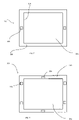
- FIG. 1 illustrates a plan view of example of a filter device 100.
- the filter device 100 includes a housing 102 for containing a liquid.
- the liquid may be engine oil for example.
- the housing 102 may have an inlet 104 and an outlet 106. In some cases, the housing 102 may have multiple inlets 104 and/or outlets 106.
- the inlet 104 allows liquid entry into the housing 102 and the outlet allows liquid to exit the housing 106, this may be valve controlled or passive, for example.
- the liquid may be driven into and out of the housing 102 by a pump apparatus (not shown).
- the housing 102 is partitioned by a filtration medium 108. That is the filtration medium 108 divides the housing 102 such that liquid is directed therethrough for filtering.
- the filtration medium 108 is configured to remove particulates from the liquid when the liquid passes therethrough.
- the filtration medium 108 may partition the housing 102 such that the filtration medium is between the inlet 104 and the outlet 106. In this way a liquid enters the housing 102 via the inlet 104 and must pass through the filtration medium 108 to exit the housing via the outlet 106.
- Suitable filtration media include but are not limited to a glass fibre or plastic fibre impregnated with resin. Suitably, this may be provided as a woven or non-woven fabric.
- the filtration medium 108 may be a single sheet of material or a plurality of stacked sheets for example. Moreover, in some examples the filtration medium 108 may be gathered or bunched etc to create a stacked arrangement of the filtration medium 108. A further option is that the filtration medium could be pleated, as well as or instead of being stacked.
- the filtration medium 108 is at least partially supported by a frame 110.
- the frame 110 supports at least part of a periphery 109 of the filtration medium 108.
- Figures 2 and 3 illustrate examples of the frame 110 supporting the periphery 109 of the filtration medium 108.
- the frame 110 may support the filtration medium 108 such that the filtration medium 108 extends wholly across the housing 102 (other than the frame 110 itself).
- the edge portion of the filtration medium is attached to the frame 110 such that the filtration medium 108 is held by the frame 110.
- the frame 110 may sandwich the periphery 109 of the filtration medium 108 between two frame portions, or a suitable adhesive may be used, or any other technique known to the person skilled in the art of designing filters.
- the frame 110 extends around the whole periphery 109 of the filtration medium 108. The frame 110 may be minimised in projection from the housing so as to reduce the liquid-non permeable area taken up in the filter device 100.
- the frame 110 may be formed of a liquid impermeable material for example plastic (as may be the housing 102).
- the frame 110 may be a substantially rigid structure so as to provide increased support to the filtration medium 108.
- the frame 110 may form a connecting portion between the periphery 109 of the filtration medium 108 and the housing 102. That is to the extent that the filtration medium 108 partitions the housing 102 the frame provides the interface between the housing 102 and the filtration medium 108.
- the frame 110 may be a separate component to the housing 102.
- the frame 110 and the housing 102 may be integral or otherwise coupled together.
- the housing 102 may include a protrusion (see figure 5b ) which extends to support the periphery 109 of the filtration medium 108 in the same manner as the frame 110.
- the frame 110 is part of the housing 102 it is only separately identified in order to explain how it includes apertures, as discussed below.
- the frame 110 includes at least one aperture 116.
- the aperture 116 extends through the frame 110 such that liquid can pass through the frame 110.
- the frame 110 includes two apertures 116.
- the frame 110 can include one or more apertures 116 and the number of apertures may be dependent on the final engine use and/or liquid type for example.
- Figure 3 for example illustrates a frame with six apertures 116.
- the apertures 116 may be evenly spaced about the frame 110. Further the apertures may be identical such that the flow through each aperture is constant. Alternatively, the apertures 116 may be sized or shaped differently for example in cases where the inlet 104 is positioned closer to one aperture 116 than another, and/or be irregularly distributed about the frame 110.
- the apertures 116 provide an alternative pathway for liquid flowing in the housing 102. In this way a portion of the liquid which is flowing through the housing 102 is able to bypass the filtration medium 108 by passing through one of the apertures 116. This reduces the pressure drop across the filtration medium 108, particularly at lower temperatures. Furthermore, as the liquid cycles through the engine the portion of liquid bypassing the filtration medium 108 has a low likelihood of being the same portion each cycle. In this way the liquid is filtered by a filtration medium 108 with a high filtration efficiency while also reducing the pressure drop across the filtration medium 108.
- the filter device 100 may include additional filtration medium 118, shown for example in figure 4.
- Figure 4 shows an example of a filter device 100 which includes a second filtration medium 118 partitioning the housing.
- the second filtration medium 118 has a lower filtration efficiency than the first filtration medium 108 described with reference to figure 1 .
- the second filtration medium 118 does not require a bypass because the pressure drop across the second filtration medium 118 is reduced by the reduction in efficiency.
- a second filtration medium 118 with the same efficiency as the first filtration medium may also be used with an aperture acting as a second bypass.
- the second filtration medium is positioned between the first filtration medium 108 and the outlet 106.
- the liquid is filtered first by the first filtration medium 108 with a high filtration efficiency, then the liquid is filtered by the second filtration medium 118 with the lower efficiency.
- the second filtration medium 118 does not have a frame 110 with an aperture 116, and thus has no bypass for the liquid. In this way, the liquid which bypasses the first filtration medium 108 is filtered by the second filtration medium 118.
- the filter device 100 may have a second filtration medium 118 between the inlet 104 and the first filtration medium 108 such that all the liquid is filtered through a filtration medium 118 of lower filtration efficiency before being filtered by the higher filtration efficiency filtration medium 108 which includes the bypass.
- the apertures 116 may have a second filtration medium 118 across or within them.
- the second filtration medium 118 may have a lower filtration efficiency than the first filtration medium 108. In this way, the liquid bypassing the first filtration medium 108 is filtered by the second filtration medium 118 in the aperture 116.
- Figure 4 also illustrates an example aperture 116 with a sinuous path.
- the aperture 116 may have a z-shaped cross section.
- the pathway through the frame 110 may not be direct. This causes the liquid to change direction when flowing through the aperture 116.
- the change in direction in some examples causes contaminating particles to continue into the first filtration medium rather than bypass the first filtration medium.
- the pathways may be identical for each aperture 116 or may alter in size and shape.
- Figure 5a to 5c illustrate a filter device 500 in which the frame 110 and housing 102 are integral.
- the frame 110 of figure 5b includes a first portion 110a and a second portion 110b which are coupled together. This coupling provides a pathway therebetween which is the aperture 116.
- Figures 5a to 5c also illustrate the flow velocity of the liquid.
- the darker areas (red and orange) illustrating areas of lower speed and the lighter areas (blues and greens) are relatively high velocity areas.
- the liquid flows through the aperture 116 at a higher speed compared with the liquid passing though the filtration medium 108.
- figure 6a illustrates the pressure drop across a filtration medium with and without an aperture acting as a bypass for the filtration medium at varying flow rates when the oil temperature is 70°C. As shown in the graph, the pressure drop across the filtration medium is higher when a bypass is not present.
- Figure 6b illustrates the same configuration as figure 6a but at a lower temperature of 0°C. The pressure drop with increasing flow rate is higher at the lower temperature. In addition the difference in pressure drop with and without a bypass is larger at lower temperatures.
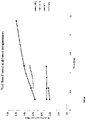
- Figure 6c illustrates the percentage of the oil which is filtered by a filter device at different flow rates.
- the filter device has a frame including an aperture according to the present invention.
- Each line indicates a different oil temperature.
- the presence of a bypass reduces in effect as the temperature increases toward normal working temperature. In this sense, the bypass has the required effect at the lower temperatures (the cold starting temperature) of reducing the pressure drop across the filtration medium, without reducing the overall filtration during normal use (at higher temperatures).
- the filter device may include housings of alternate shapes, for example a circular housing.
- FIG. 7 illustrates a plan view of another example of a filter device 700 according to the invention.
- the filter device 700 includes a housing 702 for containing a liquid.
- the liquid may be engine oil for example.
- the housing 702 may have an inlet 704 and an outlet 706. In some cases, the housing 702 may have multiple inlets 704 and/or outlets 706.
- the inlet 704 allows liquid entry into the housing 702 and the outlet allows liquid to exit the housing 706, this may be valve controlled or passive, for example.
- the liquid may be driven into and out of the housing 702 by a pump apparatus (not shown).
- the housing 702 is partitioned by a first filtration medium 708.
- first filtration medium 708 comprises an aperture 710 extending therethrough, such that a portion of the liquid can pass through the aperture 710 and bypass the first filtration medium 708. The other portion of the liquid is directed through the first filtration medium 708 for filtering.
- the aperture 710 is obtained thanks to ultrasonic wave cutting.
- the aperture 710 can also be obtained or cut thanks to cold stamping.
- the first filtration medium can comprise several apertures.
- the first filtration medium is a felt. It may also be a screen or any other type of filtration medium.
- the housing 702 further comprises a second filtration medium 712 which divides the housing 702 such that liquid is directed therethrough for filtering.
- the second filtration medium is a screen. It may also be a felt or any other type of filtration medium.
- the second filtration medium may also comprise at least one aperture, for example at least one bypass aperture.
- the filter device may further comprise a spacer (for instance a plastic insert) positioned between the first filtration medium and the second filtration medium.
- a spacer for instance a plastic insert
- the housing 702 is made of two separate shells or portions 7021, 7022 which are joined or connected together at their peripheries 7023, 7024 for instance thanks to a welding step or thanks to any other fastening mean (glue, screws, clip, ).
- the two shells 7021, 7022 and at least one of the first filtration medium 708 and the second filtration medium 712 may be joined altogether at their peripheries.
- the filter device does not comprise the second filtration medium 712 and the spacer 714.
- the first filtration medium 708 may partition the housing 702 such that the filtration medium is between the inlet 704 and the outlet 706. In this way a liquid enters the housing 702 via the inlet 104 and must pass through the filtration medium 708 or its aperture 710 to exit the housing via the outlet 706.
- the second filtration medium 712 is configured to remove particulates from the liquid when the liquid passes therethrough.
- Suitable filtration media include but are not limited to a glass fibre or plastic fibre impregnated with resin or any other fibre, plastic or metallic net. Suitably, this may be provided as a woven or non-woven fabric.
- Each of the first filtration medium 708 and the second filtration medium may be a single sheet of material or a plurality of stacked sheets for example.
- the filtration medium 708, 712 may be gathered or bunched etc to create a stacked arrangement of the filtration medium 708, 712.
- the filtration medium could be pleated, as well as or instead of being stacked.
- the first filtration medium and the second filtration medium are joined at their peripheries and wherein the spacer maintains a space between the first filtration medium and the second filtration medium.
- the joined or connected filtration medium may therefore form a bag.
- the first and second filtration mediums are joined or connected at their periphery by welding (eg by ultrasonic welding).
- FIG 8 illustrates a plan view of another example of a filter device 800 according to the invention.
- the filter device 800 includes a housing 802 for containing a liquid.
- the liquid may be engine oil for example.
- the housing 802 may have an inlet 804 and an outlet 806. In some cases, the housing 802 may have multiple inlets 804 and/or outlets 806.
- the inlet 804 allows liquid entry into the housing 802 and the outlet allows liquid to exit the housing 806, this may be valve controlled or passive, for example.
- the liquid may be driven into and out of the housing 802 by a pump apparatus (not shown).
- the housing 802 is partitioned by a first filtration medium 808.
- first filtration medium 808 comprises apertures 810 extending therethrough, such that a portion of the liquid can pass through the apertures 810 and bypass the first filtration medium 808. The other portion of the liquid is directed through the first filtration medium 808 for filtering.
- the apertures 810 are obtained thanks to ultrasonic wave cutting.
- the aperture 810 can also be obtained or cut thanks to cold stamping.
- the first filtration medium can comprise one or several apertures.
- the first filtration medium is a felt. It may also be a screen or any other type of filtration medium.
- the first filtration medium is a high efficiency filtration medium.
- high efficiency in the context of the present invention is to be understood as meaning an efficiency above 80% for particle size of 30 ⁇ m.
- the apertures 810 are bypass holes.
- the housing 802 further comprises a second filtration medium 812 which divides the housing 802 such that liquid is directed therethrough for filtering.
- the second filtration medium is a screen. It may also be a felt or any other type of filtration medium.
- the second filtration medium may also comprise at least one aperture, for example at least one bypass aperture.
- the second filtration medium 812 is a low efficiency filtration medium. Preferentially, low efficiency in the context of the present invention is to be understood as meaning an efficiency below 80% for particle size of 30 ⁇ m.
- the second filtration medium 812 is implemented to protect the first filtration medium 808.
- the second filtration medium can be used to prevent or slow down the clogging of the first filtration medium 808.
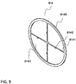
- the housing 802 further comprises a third filtration medium 814 which is illustrated by Fig. 9 .
- the third filtration medium 814 comprises a frame 8140 to which is/are attached at least one filtration medium 8143.
- four filtration medium 8143 which are for instance four plastic screens (of course it can also be metallic screens) are attached to the frame 8140.
- the frame 8140 for instance comprises four legs 8141.
- the frame comprises one or several lugs 8142.
- said one or several lug(s) is(are) at least partially obturating said at least one aperture(s).
- the frame 8140 is made of plastic and is overmolded.
- the frame is made of PA6 or PA66 plastic.
- the frame 8140 has a role of spacer or is a spacer within the housing.
- At least one of the lugs 8142 is penetrating an (or several) aperture(s) 810 (hereafter "corresponding aperture(s)”) of the first filtration medium.
- said at least one of the lugs 8142 is partially or totally obturating the corresponding aperture(s) 810.
- the frame is provided with a quantity of lugs 8142 such that each of the apertures 810 is partially or totally obturated by a lug 8142 except one or several aperture(s) 810 which is(are) not obturated by a lug.
- the housing 802 is made of two separate shells or portions 8021, 8022 which are joined or connected together at their peripheries 8023, 8024 for instance thanks to a welding step or thanks to any other fastening mean (glue, screws, clip, ).
- the third filtration medium 814 is welded to the top shell or portion 8021 thanks to a laser before the two shells or portions are joined or connected together.
- the two shells 8021, 8022 and at least one of the first filtration medium 808 and the second filtration medium 812 may be joined altogether at their peripheries.
- the filter device does not comprise the second filtration medium 812.
- the second filtration medium 812 is configured to remove particulates from the liquid when the liquid passes therethrough.
- Suitable filtration media include but are not limited to a glass fibre or plastic fibre impregnated with resin or any other fibre, plastic or metallic net. Suitably, this may be provided as a woven or non-woven fabric.
- Each of the first filtration medium 808 and the second filtration medium 812 may be a single sheet of material or a plurality of stacked sheets for example.
- the filtration medium 808, 812 may be gathered or bunched etc to create a stacked arrangement of the filtration medium 808, 812.
- the filtration medium could be pleated, as well as or instead of being stacked.
- the first filtration medium and the second filtration medium are joined at their peripheries and wherein the third filtration medium or spacer maintains a space between the first filtration medium and the second filtration medium.
- the joined or connected filtration medium may therefore form a bag.
- the first and second filtration mediums are joined or connected at their periphery by welding (eg by ultrasonic welding).
- the bottom shell 8022 and the frame 8140 are pinching or fixing the first filtration medium 808 and the second filtration medium 812.
- the frame 8140 can be welded to the upper shell 8021.
Landscapes
- Engineering & Computer Science (AREA)
- General Engineering & Computer Science (AREA)
- Mechanical Engineering (AREA)
- Chemical & Material Sciences (AREA)
- Chemical Kinetics & Catalysis (AREA)
- Lubrication Details And Ventilation Of Internal Combustion Engines (AREA)
Abstract
Description
- The present invention relates to a filter device and particularly, but not exclusively, to a filter device for filtering a liquid such as oil in a vehicle engine which provides a reduced pressure drop across a filtration medium at low temperatures.
- Typically, a filter device for filtering engine oil provides continuous cleaning to the engine oil. The filter device removes particulates such as carbon, soot and metals for example. Filters often comprise at least one highly efficient filtration medium which allows for removal of very fine particulates within the engine oil by passing the oil through the filtration medium. For modern vehicles there is an increasing need to remove smaller particles from the oil by increasing the efficiency of the filtration medium.
- When an engine is running at standard or high temperatures, the viscosity of the oil is of a low enough level that the pressure drop across the filtration medium remains within acceptable limits. However, engine oil has increased viscosity at lower temperatures, for example when starting an engine from cold. This high viscosity means a large force is required to push the liquid through the filtration medium and particularly highly efficient filtration medium, resulting in a high pressure drop across the filtration medium. The oil pump must therefore increase the force it exerts to drive the oil through the filtration medium at colder temperatures. If the pressure drop across the filtration medium is too high, the flow of oil through the engine may be impeded risking engine damage. Damage may also be caused to the filtration medium.
- It is known to provide a filtration medium with holes dispersed throughout the body of the filtration medium. However, this has the drawback that the edge of the hole in the filtration medium can be rough which can allow for parts of the filtration medium to dislodge and contaminate the oil, further risking engine damage.
- It is an aim of certain examples of the present invention to solve, mitigate or obviate, at least partly, at least one of the problems and/or disadvantages associated with the prior art
- The present invention provides a filter device as claimed in the appended claims.
- According to an aspect of the invention, there is provided a filter device comprising: a housing; a first filtration medium within the housing such that for a liquid passing through the housing at least a portion is filtered by the first filtration medium; and a bypass for allowing a portion 'of the liquid to bypass the first filtration medium.
- The filter device may comprise a frame supporting at least a portion of a periphery of the first filtration medium. The frame may comprise at least one aperture extending therethrough, e.g. such that a portion of the liquid can pass through the at least one aperture and bypass the first filtration medium.
- According to another aspect of the invention, there is provided a filter device comprising: a housing; a first filtration medium within the housing such that for a liquid passing through the housing at least a portion is filtered by the first filtration medium; and a frame supporting at least a portion of a periphery of the first filtration medium; wherein the frame comprises at least one aperture extending therethrough, such that a portion of the liquid can pass through the at least one aperture and bypass the first filtration medium.
- The filter device may further comprise a second filtration medium within the housing, such that at least the portion of the liquid which bypasses the first filtration medium passes through the second filtration medium.
- Preferentially, the first filtration medium has a first filtration efficiency and the second filtration medium has a second filtration efficiency, which may be lower than the first filtration efficiency.
- The housing may comprise a liquid inlet on a first side of the first filtration medium and a liquid outlet on a second side of the first filtration medium and the second filtration medium may be positioned between the inlet or outlet and the first filtration medium.
- The second filtration medium may be positioned across or within the at least one aperture.
- The frame may comprise at least a first frame portion and a second frame portion coupled together, and the aperture may be a pathway between the first frame portion and the second frame portion.
- The aperture may comprise a sinuous pathway.
- The frame may comprise a plurality of apertures.
- The frame may comprise a liquid impermeable material.
- The frame may be integral to or forms part of the housing.
- The housing may comprise first and second housing portions which when coupled together form the frame and the aperture therethrough.
- The first filtration medium may comprise at least one aperture extending therethrough, e.g. such that a portion of the liquid can pass through the at least one aperture and bypass the first filtration medium.
- According to another aspect of the invention, there is provided a filter device comprising: a housing, a first filtration medium within the housing such that for a liquid passing through the housing at least a portion is filtered by the first filtration medium; and wherein the first filtration medium comprises at least one aperture extending therethrough, such that a portion of the liquid can pass through the at least one aperture and bypass the first filtration medium. According to an implementation of the invention, such a filter device may not comprise any frame around the first filtration medium.
- At least one aperture may be formed by or obtained thanks to ultrasonic wave cutting or formed by or thanks to cold stamping. Therefore, a clean cut can be obtained.
- The filter device may further comprise: a second filtration medium within the housing and at least a spacer between the first filtration medium and the second filtration medium. According to an implementation of the invention, such a filter device may not comprise any frame around the second filtration medium. According to an implementation of the invention, such the spacer may be a plastic insert between the first filtration medium and the second filtration medium.
- The spacer may be molded for instance by plastic molding.
- The first filtration medium and the second filtration medium may be joined or connected at their peripheries. The spacer may maintain a space (or a gap) between the first filtration medium and the second filtration medium. The joined or connected filtration medium may therefore form a bag.
- The first and second filtration mediums may be joined or connected at their periphery by welding (eg by ultrasonic welding).
- The filter device may further comprise a second filtration medium, which may be a low efficiency filtration medium. Preferentially said second filtration medium is protecting the first filtration medium.
- The filter may further comprise: a third filtration medium within the housing comprising a frame and at least one filtration medium attached to the frame.
- Preferentially, the frame further comprises at least one lug, said at least one lug at least partially obturating said at least one aperture.
- The frame may be made of plastic and/or may be overmolded.
- Examples of the invention are further described hereinafter with reference to the accompanying drawings, in which:
-
Figure 1 illustrates a plan view of an example of a filter device; -
Figure 2 illustrates a front view of an example frame and filtration medium; -
Figure 3 illustrates a front view of a further example frame and filtration medium; -
Figure 4 illustrates a plan view showing a further example of a filter device; -
Figure 5a illustrates a plan view of the liquid flow through an example of a filter device; -
Figure 5b illustrates an enlarged view of an aperture of the filter device ofFigure 5a ; -
Figure 5c illustrates a front view of the filter device ofFigure 5a ; -
Figure 6a illustrates a graph of the pressure drop across a filter with a bypass compared to without a bypass at a liquid temperature of 70°C; -
Figure 6b illustrates a graph of the pressure drop across a filter with a bypass compared to without a bypass at a liquid temperature of 0°C; and -
Figure 6c illustrates a graph of the percentage of the flow filtered with a bypass at varying temperatures; -
Figure 7 illustrates a plan view of another example of a filter device according to the present invention; -
Figure 8 illustrates a plan view of a further example of a filter device according to the present invention; -
Figure 9 illustrates a perspective view of a third filtration medium according to the present invention for the filter device offigure 8 ; - Throughout the detailed description like numerals refer to like parts.
-
Figure 1 illustrates a plan view of example of afilter device 100. Thefilter device 100 includes ahousing 102 for containing a liquid. The liquid may be engine oil for example. Thehousing 102 may have aninlet 104 and anoutlet 106. In some cases, thehousing 102 may havemultiple inlets 104 and/oroutlets 106. Theinlet 104 allows liquid entry into thehousing 102 and the outlet allows liquid to exit thehousing 106, this may be valve controlled or passive, for example. In some examples the liquid may be driven into and out of thehousing 102 by a pump apparatus (not shown). - The
housing 102 is partitioned by afiltration medium 108. That is thefiltration medium 108 divides thehousing 102 such that liquid is directed therethrough for filtering. Thefiltration medium 108 is configured to remove particulates from the liquid when the liquid passes therethrough. For example, thefiltration medium 108 may partition thehousing 102 such that the filtration medium is between theinlet 104 and theoutlet 106. In this way a liquid enters thehousing 102 via theinlet 104 and must pass through thefiltration medium 108 to exit the housing via theoutlet 106. - Examples of suitable filtration media include but are not limited to a glass fibre or plastic fibre impregnated with resin. Suitably, this may be provided as a woven or non-woven fabric. The
filtration medium 108 may be a single sheet of material or a plurality of stacked sheets for example. Moreover, in some examples thefiltration medium 108 may be gathered or bunched etc to create a stacked arrangement of thefiltration medium 108. A further option is that the filtration medium could be pleated, as well as or instead of being stacked. - The
filtration medium 108 is at least partially supported by aframe 110. Theframe 110 supports at least part of aperiphery 109 of thefiltration medium 108.Figures 2 and 3 illustrate examples of theframe 110 supporting theperiphery 109 of thefiltration medium 108. Theframe 110 may support thefiltration medium 108 such that thefiltration medium 108 extends wholly across the housing 102 (other than theframe 110 itself). - To support the periphery of the
filtration medium 108, the edge portion of the filtration medium is attached to theframe 110 such that thefiltration medium 108 is held by theframe 110. For example, theframe 110 may sandwich theperiphery 109 of thefiltration medium 108 between two frame portions, or a suitable adhesive may be used, or any other technique known to the person skilled in the art of designing filters. In some examples theframe 110 extends around thewhole periphery 109 of thefiltration medium 108. Theframe 110 may be minimised in projection from the housing so as to reduce the liquid-non permeable area taken up in thefilter device 100. - The
frame 110 may be formed of a liquid impermeable material for example plastic (as may be the housing 102). Theframe 110 may be a substantially rigid structure so as to provide increased support to thefiltration medium 108. Theframe 110 may form a connecting portion between theperiphery 109 of thefiltration medium 108 and thehousing 102. That is to the extent that thefiltration medium 108 partitions thehousing 102 the frame provides the interface between thehousing 102 and thefiltration medium 108. - The
frame 110 may be a separate component to thehousing 102. In some examples theframe 110 and thehousing 102 may be integral or otherwise coupled together. For example, thehousing 102 may include a protrusion (seefigure 5b ) which extends to support theperiphery 109 of thefiltration medium 108 in the same manner as theframe 110. Where theframe 110 is part of thehousing 102 it is only separately identified in order to explain how it includes apertures, as discussed below. - The
frame 110 includes at least oneaperture 116. Theaperture 116 extends through theframe 110 such that liquid can pass through theframe 110. In the example offigure 2 theframe 110 includes twoapertures 116. It will be understood that theframe 110 can include one ormore apertures 116 and the number of apertures may be dependent on the final engine use and/or liquid type for example.Figure 3 for example illustrates a frame with sixapertures 116. Theapertures 116 may be evenly spaced about theframe 110. Further the apertures may be identical such that the flow through each aperture is constant. Alternatively, theapertures 116 may be sized or shaped differently for example in cases where theinlet 104 is positioned closer to oneaperture 116 than another, and/or be irregularly distributed about theframe 110. - The
apertures 116 provide an alternative pathway for liquid flowing in thehousing 102. In this way a portion of the liquid which is flowing through thehousing 102 is able to bypass thefiltration medium 108 by passing through one of theapertures 116. This reduces the pressure drop across thefiltration medium 108, particularly at lower temperatures. Furthermore, as the liquid cycles through the engine the portion of liquid bypassing thefiltration medium 108 has a low likelihood of being the same portion each cycle. In this way the liquid is filtered by afiltration medium 108 with a high filtration efficiency while also reducing the pressure drop across thefiltration medium 108. - The
filter device 100 may includeadditional filtration medium 118, shown for example infigure 4. Figure 4 shows an example of afilter device 100 which includes asecond filtration medium 118 partitioning the housing. Thesecond filtration medium 118 has a lower filtration efficiency than thefirst filtration medium 108 described with reference tofigure 1 . In this way, thesecond filtration medium 118 does not require a bypass because the pressure drop across thesecond filtration medium 118 is reduced by the reduction in efficiency. Of course, asecond filtration medium 118 with the same efficiency as the first filtration medium may also be used with an aperture acting as a second bypass. - In the example shown in
figure 4 the second filtration medium is positioned between thefirst filtration medium 108 and theoutlet 106. In this way, the liquid is filtered first by thefirst filtration medium 108 with a high filtration efficiency, then the liquid is filtered by thesecond filtration medium 118 with the lower efficiency. However, thesecond filtration medium 118 does not have aframe 110 with anaperture 116, and thus has no bypass for the liquid. In this way, the liquid which bypasses thefirst filtration medium 108 is filtered by thesecond filtration medium 118. Alternatively, or in addition thefilter device 100 may have asecond filtration medium 118 between theinlet 104 and thefirst filtration medium 108 such that all the liquid is filtered through afiltration medium 118 of lower filtration efficiency before being filtered by the higher filtrationefficiency filtration medium 108 which includes the bypass. - In some (not shown) examples the
apertures 116 may have asecond filtration medium 118 across or within them. Thesecond filtration medium 118 may have a lower filtration efficiency than thefirst filtration medium 108. In this way, the liquid bypassing thefirst filtration medium 108 is filtered by thesecond filtration medium 118 in theaperture 116. -
Figure 4 also illustrates anexample aperture 116 with a sinuous path. For example, theaperture 116 may have a z-shaped cross section. In other words, the pathway through theframe 110 may not be direct. This causes the liquid to change direction when flowing through theaperture 116. The change in direction in some examples causes contaminating particles to continue into the first filtration medium rather than bypass the first filtration medium. In examples of afilter device 100 withapertures 116 having sinuous pathways, the pathways may be identical for eachaperture 116 or may alter in size and shape. -
Figure 5a to 5c illustrate afilter device 500 in which theframe 110 andhousing 102 are integral. Theframe 110 offigure 5b includes afirst portion 110a and asecond portion 110b which are coupled together. This coupling provides a pathway therebetween which is theaperture 116. -
Figures 5a to 5c also illustrate the flow velocity of the liquid. The darker areas (red and orange) illustrating areas of lower speed and the lighter areas (blues and greens) are relatively high velocity areas. As can be seen, the liquid flows through theaperture 116 at a higher speed compared with the liquid passing though thefiltration medium 108. - To further illustrate the advantageous effects of the filter device
figure 6a illustrates the pressure drop across a filtration medium with and without an aperture acting as a bypass for the filtration medium at varying flow rates when the oil temperature is 70°C. As shown in the graph, the pressure drop across the filtration medium is higher when a bypass is not present.Figure 6b illustrates the same configuration asfigure 6a but at a lower temperature of 0°C. The pressure drop with increasing flow rate is higher at the lower temperature. In addition the difference in pressure drop with and without a bypass is larger at lower temperatures. -
Figure 6c illustrates the percentage of the oil which is filtered by a filter device at different flow rates. The filter device has a frame including an aperture according to the present invention. Each line indicates a different oil temperature. As can be seen, as the temperature increases the amount of liquid filtered increases. Thus, the presence of a bypass reduces in effect as the temperature increases toward normal working temperature. In this sense, the bypass has the required effect at the lower temperatures (the cold starting temperature) of reducing the pressure drop across the filtration medium, without reducing the overall filtration during normal use (at higher temperatures). - Although illustrated throughout the application as a square housing portioned by a sheet of filtration medium, other iterations of the filter device may include housings of alternate shapes, for example a circular housing.
-
Figure 7 illustrates a plan view of another example of afilter device 700 according to the invention. Thefilter device 700 includes ahousing 702 for containing a liquid. The liquid may be engine oil for example. Thehousing 702 may have aninlet 704 and anoutlet 706. In some cases, thehousing 702 may havemultiple inlets 704 and/oroutlets 706. Theinlet 704 allows liquid entry into thehousing 702 and the outlet allows liquid to exit thehousing 706, this may be valve controlled or passive, for example. In some examples the liquid may be driven into and out of thehousing 702 by a pump apparatus (not shown). - The
housing 702 is partitioned by afirst filtration medium 708. Suchfirst filtration medium 708 comprises anaperture 710 extending therethrough, such that a portion of the liquid can pass through theaperture 710 and bypass thefirst filtration medium 708. The other portion of the liquid is directed through thefirst filtration medium 708 for filtering. - According to an aspect of the invention, the
aperture 710 is obtained thanks to ultrasonic wave cutting. Of course, alternatively, theaperture 710 can also be obtained or cut thanks to cold stamping. Of course, the first filtration medium can comprise several apertures. - For instance, the first filtration medium is a felt. It may also be a screen or any other type of filtration medium.
- The
housing 702 further comprises asecond filtration medium 712 which divides thehousing 702 such that liquid is directed therethrough for filtering. For instance, the second filtration medium is a screen. It may also be a felt or any other type of filtration medium. The second filtration medium may also comprise at least one aperture, for example at least one bypass aperture. - The filter device may further comprise a spacer (for instance a plastic insert) positioned between the first filtration medium and the second filtration medium.
- According to an aspect of the invention, the
housing 702 is made of two separate shells orportions peripheries shells first filtration medium 708 and thesecond filtration medium 712 may be joined altogether at their peripheries. - According to another example not illustrated on
Fig. 7 , the filter device does not comprise thesecond filtration medium 712 and thespacer 714. For example, in that case, thefirst filtration medium 708 may partition thehousing 702 such that the filtration medium is between theinlet 704 and theoutlet 706. In this way a liquid enters thehousing 702 via theinlet 104 and must pass through thefiltration medium 708 or itsaperture 710 to exit the housing via theoutlet 706. - According to an aspect of the invention, the
second filtration medium 712 is configured to remove particulates from the liquid when the liquid passes therethrough. - Examples of suitable filtration media include but are not limited to a glass fibre or plastic fibre impregnated with resin or any other fibre, plastic or metallic net. Suitably, this may be provided as a woven or non-woven fabric. Each of the
first filtration medium 708 and the second filtration medium may be a single sheet of material or a plurality of stacked sheets for example. Moreover, in some examples thefiltration medium filtration medium - According to an aspect of the invention, the first filtration medium and the second filtration medium are joined at their peripheries and wherein the spacer maintains a space between the first filtration medium and the second filtration medium. The joined or connected filtration medium may therefore form a bag.
- According to an aspect of the invention, the first and second filtration mediums are joined or connected at their periphery by welding (eg by ultrasonic welding).
-
Figure 8 illustrates a plan view of another example of afilter device 800 according to the invention. Thefilter device 800 includes ahousing 802 for containing a liquid. The liquid may be engine oil for example. Thehousing 802 may have aninlet 804 and anoutlet 806. In some cases, thehousing 802 may havemultiple inlets 804 and/oroutlets 806. Theinlet 804 allows liquid entry into thehousing 802 and the outlet allows liquid to exit thehousing 806, this may be valve controlled or passive, for example. In some examples the liquid may be driven into and out of thehousing 802 by a pump apparatus (not shown). - The
housing 802 is partitioned by afirst filtration medium 808. Suchfirst filtration medium 808 comprisesapertures 810 extending therethrough, such that a portion of the liquid can pass through theapertures 810 and bypass thefirst filtration medium 808. The other portion of the liquid is directed through thefirst filtration medium 808 for filtering. - According to an aspect of the invention, the
apertures 810 are obtained thanks to ultrasonic wave cutting. Of course, alternatively, theaperture 810 can also be obtained or cut thanks to cold stamping. Of course, the first filtration medium can comprise one or several apertures. - For instance, the first filtration medium is a felt. It may also be a screen or any other type of filtration medium. Preferentially, the first filtration medium is a high efficiency filtration medium. Preferentially, high efficiency in the context of the present invention is to be understood as meaning an efficiency above 80% for particle size of 30µm.
- Preferentially, the
apertures 810 are bypass holes. - The
housing 802 further comprises asecond filtration medium 812 which divides thehousing 802 such that liquid is directed therethrough for filtering. For instance, the second filtration medium is a screen. It may also be a felt or any other type of filtration medium. The second filtration medium may also comprise at least one aperture, for example at least one bypass aperture. Preferentially, thesecond filtration medium 812 is a low efficiency filtration medium. Preferentially, low efficiency in the context of the present invention is to be understood as meaning an efficiency below 80% for particle size of 30µm. - Preferentially, the
second filtration medium 812 is implemented to protect thefirst filtration medium 808. Preferentially, the second filtration medium can be used to prevent or slow down the clogging of thefirst filtration medium 808. - Preferentially, the
housing 802 further comprises athird filtration medium 814 which is illustrated byFig. 9 . - For instance, the
third filtration medium 814 comprises aframe 8140 to which is/are attached at least onefiltration medium 8143. In the example offigure 9 , fourfiltration medium 8143 which are for instance four plastic screens (of course it can also be metallic screens) are attached to theframe 8140. Theframe 8140 for instance comprises fourlegs 8141. Preferentially, the frame comprises one orseveral lugs 8142. Preferentially, said one or several lug(s) is(are) at least partially obturating said at least one aperture(s). - Preferentially, the
frame 8140 is made of plastic and is overmolded. For instance, the frame is made of PA6 or PA66 plastic. Preferentially, theframe 8140 has a role of spacer or is a spacer within the housing. - Preferentially, at least one of the
lugs 8142 is penetrating an (or several) aperture(s) 810 (hereafter "corresponding aperture(s)") of the first filtration medium. Preferentially, said at least one of thelugs 8142 is partially or totally obturating the corresponding aperture(s) 810. Preferentially, the frame is provided with a quantity oflugs 8142 such that each of theapertures 810 is partially or totally obturated by alug 8142 except one or several aperture(s) 810 which is(are) not obturated by a lug. - According to an aspect of the invention, the
housing 802 is made of two separate shells orportions peripheries third filtration medium 814 is welded to the top shell orportion 8021 thanks to a laser before the two shells or portions are joined or connected together. - As an example, the two
shells first filtration medium 808 and thesecond filtration medium 812 may be joined altogether at their peripheries. - According to another example not illustrated on
Fig. 8 , the filter device does not comprise thesecond filtration medium 812. - According to an aspect of the invention, the
second filtration medium 812 is configured to remove particulates from the liquid when the liquid passes therethrough. - Examples of suitable filtration media include but are not limited to a glass fibre or plastic fibre impregnated with resin or any other fibre, plastic or metallic net. Suitably, this may be provided as a woven or non-woven fabric. Each of the
first filtration medium 808 and thesecond filtration medium 812 may be a single sheet of material or a plurality of stacked sheets for example. Moreover, in some examples thefiltration medium filtration medium - According to an aspect of the invention, the first filtration medium and the second filtration medium are joined at their peripheries and wherein the third filtration medium or spacer maintains a space between the first filtration medium and the second filtration medium. The joined or connected filtration medium may therefore form a bag.
- According to an aspect of the invention, the first and second filtration mediums are joined or connected at their periphery by welding (eg by ultrasonic welding). Alternatively, the
bottom shell 8022 and theframe 8140 are pinching or fixing thefirst filtration medium 808 and thesecond filtration medium 812. Theframe 8140 can be welded to theupper shell 8021. - Throughout this specification, the words "comprise" and "contain" and variations of them mean "including but not limited to", and they are not intended to (and do not) exclude other components, integers or steps. Throughout this specification, the singular encompasses the plural unless the context otherwise requires. In particular, where the indefinite article is used, the specification is to be understood as contemplating plurality as well as singularity, unless the context requires otherwise. Throughout this specification, the term "about" is used to provide flexibility to a range endpoint by providing that a given value may be "a little above" or "a little below" the endpoint. The degree of flexibility of this term can be dictated by the particular variable and can be determined based on experience and the associated description herein.
- Features, integers or characteristics described in conjunction with a particular aspect or example of the invention are to be understood to be applicable to any other aspect or example described herein unless incompatible therewith. All of the features disclosed in this specification, and/or all of the steps of any method or process so disclosed, may be combined in any combination, except combinations where at least some of such features and/or steps are mutually exclusive. The invention is not restricted to the details of any foregoing examples. The invention extends to any novel feature or combination of features disclosed in this specification. It will be also be appreciated that, throughout this specification, language in the general form of "X for Y" (where Y is some action, activity or step and X is some means for carrying out that action, activity or step) encompasses means X adapted or arranged specifically, but not exclusively, to do Y.
- Each feature disclosed in this specification may be replaced by alternative features serving the same, equivalent or similar purpose, unless expressly stated otherwise. Thus, unless expressly stated otherwise, each feature disclosed is one example only of a generic series of equivalent or similar features.
- The reader's attention is directed to all papers and documents which are filed concurrently with or previous to this specification in connection with this application and which are open to public inspection with this specification, and the contents of all such papers and documents are incorporated herein by reference.
Claims (15)
- A filter device (100; 700; 800) comprising:a housing (102; 702; 802);a first filtration medium (108; 708; 808) within the housing such that for a liquid passing through the housing at least a portion is filtered by the first filtration medium; anda bypass (116; 710; 810) for allowing a portion of the liquid to bypass the first filtration medium.
- The filter device of claim 1, further comprising:a frame (1101) supporting at least a portion of a periphery of the first filtration medium;wherein the frame comprises at least one aperture (116) extending therethrough, such that a portion of the liquid can pass through the at least one aperture and bypass the first filtration medium.
- The filter device of claim 1 or 2, further comprising a second filtration medium (118) within the housing, such that at least the portion of the liquid which bypasses the first filtration medium passes through the second filtration medium.
- The filter device of claim 3, wherein the first filtration medium has a first filtration efficiency and the second filtration medium has a second filtration efficiency, lower than the first filtration efficiency.
- The filter device of claim 3 or claim 4, wherein the housing comprises a liquid inlet (104) on a first side of the first filtration medium and a liquid outlet (106) on a second side of the first filtration medium and wherein the second filtration medium is positioned between the inlet or outlet and the first filtration medium.
- The filter device of claim 2 in combination with claim 3 or claim 4, wherein the second filtration medium is positioned across or within the at least one aperture.
- The filter device of claim 2 in combination with any one of claims 3 to 6, wherein the frame comprises at least a first frame portion and a second frame portion coupled together, and wherein the aperture is a pathway between the first frame portion and the second frame portion.
- The filter device of claim 2 in combination with any one of claims 3 to 7, wherein the aperture comprises a sinuous pathway.
- The filter device of claim 1, wherein the first filtration medium (708; 808) comprises at least one aperture (710; 810) extending therethrough, such that a portion of the liquid can pass through the at least one aperture and bypass the first filtration medium.
- The filter device of claim 9, wherein the at least one aperture is obtained thanks to ultrasonic wave cutting or by cold stamping.
- The filter device of claim 9 or claim 10, wherein the filter device further comprises:a second filtration medium (712; 812) within the housing (792; 802); andat least a spacer (714) between the first filtration medium and the second filtration medium.
- The filter device of claim 11, wherein the first filtration medium and the second filtration medium are joined at their peripheries and wherein the spacer maintains a space between the first filtration medium and the second filtration medium.
- The filter device of claim 9 or claim 10, wherein the filter device further comprises a second filtration medium (712; 812) which is a low efficiency filtration medium.
- The filter of claim 13, wherein the filter further comprises:
a third filtration medium (814) within the housing comprising a frame (8140) and at least one filtration medium attached to the frame. - The filter device of claim 14, wherein the frame further comprises at least one lug (8142), said at least one lug at least partially obturating said at least one aperture.
Applications Claiming Priority (3)
| Application Number | Priority Date | Filing Date | Title |
|---|---|---|---|
| EP21165053 | 2021-03-25 | ||
| EP21170553 | 2021-04-26 | ||
| EP21205089 | 2021-10-27 |
Publications (2)
| Publication Number | Publication Date |
|---|---|
| EP4063622A1 true EP4063622A1 (en) | 2022-09-28 |
| EP4063622B1 EP4063622B1 (en) | 2025-02-26 |
Family
ID=81325554
Family Applications (1)
| Application Number | Title | Priority Date | Filing Date |
|---|---|---|---|
| EP22315066.5A Active EP4063622B1 (en) | 2021-03-25 | 2022-03-17 | Filter device |
Country Status (2)
| Country | Link |
|---|---|
| EP (1) | EP4063622B1 (en) |
| ES (1) | ES3029415T3 (en) |
Citations (4)
| Publication number | Priority date | Publication date | Assignee | Title |
|---|---|---|---|---|
| DE102005004287A1 (en) * | 2005-01-28 | 2006-08-03 | Mann + Hummel Gmbh | Oil filter unit |
| DE102007023641A1 (en) * | 2007-05-22 | 2008-11-27 | Ibs Filtran Kunststoff-/ Metallerzeugnisse Gmbh | Oil filter device |
| EP2143934A1 (en) * | 2007-04-26 | 2010-01-13 | Nifco INC. | Filter apparatus for fuel |
| EP2586511A1 (en) * | 2011-10-28 | 2013-05-01 | IBS Filtran Kunststoff-/Metallerzeugnisse GmbH | Filter assembly |
Family Cites Families (1)
| Publication number | Priority date | Publication date | Assignee | Title |
|---|---|---|---|---|
| DE102014009707A1 (en) * | 2014-07-02 | 2016-01-07 | Mann+Hummel Gmbh | Filter medium, filter element with a filter medium, filter system and method for producing a filter medium |
-
2022
- 2022-03-17 EP EP22315066.5A patent/EP4063622B1/en active Active
- 2022-03-17 ES ES22315066T patent/ES3029415T3/en active Active
Patent Citations (4)
| Publication number | Priority date | Publication date | Assignee | Title |
|---|---|---|---|---|
| DE102005004287A1 (en) * | 2005-01-28 | 2006-08-03 | Mann + Hummel Gmbh | Oil filter unit |
| EP2143934A1 (en) * | 2007-04-26 | 2010-01-13 | Nifco INC. | Filter apparatus for fuel |
| DE102007023641A1 (en) * | 2007-05-22 | 2008-11-27 | Ibs Filtran Kunststoff-/ Metallerzeugnisse Gmbh | Oil filter device |
| EP2586511A1 (en) * | 2011-10-28 | 2013-05-01 | IBS Filtran Kunststoff-/Metallerzeugnisse GmbH | Filter assembly |
Also Published As
| Publication number | Publication date |
|---|---|
| ES3029415T3 (en) | 2025-06-24 |
| EP4063622B1 (en) | 2025-02-26 |
Similar Documents
| Publication | Publication Date | Title |
|---|---|---|
| EP3062904B1 (en) | Filter with internal frame openings | |
| US7845500B2 (en) | Oil filter unit | |
| EP1747053B1 (en) | Filter element with off-axis end cap | |
| JP5917553B2 (en) | Fuel filter | |
| JP4965507B2 (en) | Oil filter device | |
| EP2497557B1 (en) | Dual media fluid filter | |
| US20080011672A1 (en) | Direct Flow Filter Including Auxiliary Filter | |
| CN101578127A (en) | Filter arrangement and method | |
| JP2012507392A (en) | Small fiber layer mist removal device | |
| EP4063622B1 (en) | Filter device | |
| AU2005240573A1 (en) | Tubular screen separator | |
| EP3047891B1 (en) | Filter | |
| US9975070B2 (en) | Filter with multiple media | |
| US20150129469A1 (en) | Filter with dual pleat pack | |
| US8720028B2 (en) | Replaceable filter media and holding mechanism | |
| EP3010619B1 (en) | Filter providing coarse media with high-efficiency insert | |
| US7410575B1 (en) | Fluid filter and cap member | |
| JP3462345B2 (en) | Oil strainer | |
| JP2018103112A (en) | Filter unit | |
| US20060026937A1 (en) | Filter assembly including foam and pleated media | |
| US20250375722A1 (en) | Filter device | |
| JPH04118013A (en) | Filter medium | |
| CN109847492A (en) | Device and method for separating oil particles from an air flow | |
| GB2297042A (en) | Motor vehicle oil filter |
Legal Events
| Date | Code | Title | Description |
|---|---|---|---|
| PUAI | Public reference made under article 153(3) epc to a published international application that has entered the european phase |
Free format text: ORIGINAL CODE: 0009012 |
|
| STAA | Information on the status of an ep patent application or granted ep patent |
Free format text: STATUS: THE APPLICATION HAS BEEN PUBLISHED |
|
| AK | Designated contracting states |
Kind code of ref document: A1 Designated state(s): AL AT BE BG CH CY CZ DE DK EE ES FI FR GB GR HR HU IE IS IT LI LT LU LV MC MK MT NL NO PL PT RO RS SE SI SK SM TR |
|
| STAA | Information on the status of an ep patent application or granted ep patent |
Free format text: STATUS: REQUEST FOR EXAMINATION WAS MADE |
|
| 17P | Request for examination filed |
Effective date: 20230327 |
|
| RBV | Designated contracting states (corrected) |
Designated state(s): AL AT BE BG CH CY CZ DE DK EE ES FI FR GB GR HR HU IE IS IT LI LT LU LV MC MK MT NL NO PL PT RO RS SE SI SK SM TR |
|
| GRAP | Despatch of communication of intention to grant a patent |
Free format text: ORIGINAL CODE: EPIDOSNIGR1 |
|
| STAA | Information on the status of an ep patent application or granted ep patent |
Free format text: STATUS: GRANT OF PATENT IS INTENDED |
|
| INTG | Intention to grant announced |
Effective date: 20240705 |
|
| GRAJ | Information related to disapproval of communication of intention to grant by the applicant or resumption of examination proceedings by the epo deleted |
Free format text: ORIGINAL CODE: EPIDOSDIGR1 |
|
| STAA | Information on the status of an ep patent application or granted ep patent |
Free format text: STATUS: REQUEST FOR EXAMINATION WAS MADE |
|
| P01 | Opt-out of the competence of the unified patent court (upc) registered |
Free format text: CASE NUMBER: APP_44890/2024 Effective date: 20240801 |
|
| INTC | Intention to grant announced (deleted) | ||
| GRAP | Despatch of communication of intention to grant a patent |
Free format text: ORIGINAL CODE: EPIDOSNIGR1 |
|
| STAA | Information on the status of an ep patent application or granted ep patent |
Free format text: STATUS: GRANT OF PATENT IS INTENDED |
|
| INTG | Intention to grant announced |
Effective date: 20241018 |
|
| GRAS | Grant fee paid |
Free format text: ORIGINAL CODE: EPIDOSNIGR3 |
|
| GRAA | (expected) grant |
Free format text: ORIGINAL CODE: 0009210 |
|
| STAA | Information on the status of an ep patent application or granted ep patent |
Free format text: STATUS: THE PATENT HAS BEEN GRANTED |
|
| AK | Designated contracting states |
Kind code of ref document: B1 Designated state(s): AL AT BE BG CH CY CZ DE DK EE ES FI FR GB GR HR HU IE IS IT LI LT LU LV MC MK MT NL NO PL PT RO RS SE SI SK SM TR |
|
| REG | Reference to a national code |
Ref country code: GB Ref legal event code: FG4D |
|
| REG | Reference to a national code |
Ref country code: CH Ref legal event code: EP |
|
| REG | Reference to a national code |
Ref country code: DE Ref legal event code: R096 Ref document number: 602022011087 Country of ref document: DE |
|
| REG | Reference to a national code |
Ref country code: IE Ref legal event code: FG4D |
|
| PGFP | Annual fee paid to national office [announced via postgrant information from national office to epo] |
Ref country code: AT Payment date: 20250417 Year of fee payment: 4 |
|
| REG | Reference to a national code |
Ref country code: ES Ref legal event code: FG2A Ref document number: 3029415 Country of ref document: ES Kind code of ref document: T3 Effective date: 20250624 |
|
| REG | Reference to a national code |
Ref country code: NL Ref legal event code: MP Effective date: 20250226 |
|
| PG25 | Lapsed in a contracting state [announced via postgrant information from national office to epo] |
Ref country code: RS Free format text: LAPSE BECAUSE OF FAILURE TO SUBMIT A TRANSLATION OF THE DESCRIPTION OR TO PAY THE FEE WITHIN THE PRESCRIBED TIME-LIMIT Effective date: 20250526 |
|
| PG25 | Lapsed in a contracting state [announced via postgrant information from national office to epo] |
Ref country code: FI Free format text: LAPSE BECAUSE OF FAILURE TO SUBMIT A TRANSLATION OF THE DESCRIPTION OR TO PAY THE FEE WITHIN THE PRESCRIBED TIME-LIMIT Effective date: 20250226 |
|
| PG25 | Lapsed in a contracting state [announced via postgrant information from national office to epo] |
Ref country code: PL Free format text: LAPSE BECAUSE OF FAILURE TO SUBMIT A TRANSLATION OF THE DESCRIPTION OR TO PAY THE FEE WITHIN THE PRESCRIBED TIME-LIMIT Effective date: 20250226 |
|
| PGFP | Annual fee paid to national office [announced via postgrant information from national office to epo] |
Ref country code: ES Payment date: 20250602 Year of fee payment: 4 |
|
| REG | Reference to a national code |
Ref country code: LT Ref legal event code: MG9D |
|
| PG25 | Lapsed in a contracting state [announced via postgrant information from national office to epo] |
Ref country code: NO Free format text: LAPSE BECAUSE OF FAILURE TO SUBMIT A TRANSLATION OF THE DESCRIPTION OR TO PAY THE FEE WITHIN THE PRESCRIBED TIME-LIMIT Effective date: 20250526 Ref country code: IS Free format text: LAPSE BECAUSE OF FAILURE TO SUBMIT A TRANSLATION OF THE DESCRIPTION OR TO PAY THE FEE WITHIN THE PRESCRIBED TIME-LIMIT Effective date: 20250626 |
|
| PG25 | Lapsed in a contracting state [announced via postgrant information from national office to epo] |
Ref country code: NL Free format text: LAPSE BECAUSE OF FAILURE TO SUBMIT A TRANSLATION OF THE DESCRIPTION OR TO PAY THE FEE WITHIN THE PRESCRIBED TIME-LIMIT Effective date: 20250226 |
|
| PG25 | Lapsed in a contracting state [announced via postgrant information from national office to epo] |
Ref country code: HR Free format text: LAPSE BECAUSE OF FAILURE TO SUBMIT A TRANSLATION OF THE DESCRIPTION OR TO PAY THE FEE WITHIN THE PRESCRIBED TIME-LIMIT Effective date: 20250226 |
|
| PG25 | Lapsed in a contracting state [announced via postgrant information from national office to epo] |
Ref country code: PT Free format text: LAPSE BECAUSE OF FAILURE TO SUBMIT A TRANSLATION OF THE DESCRIPTION OR TO PAY THE FEE WITHIN THE PRESCRIBED TIME-LIMIT Effective date: 20250626 Ref country code: LV Free format text: LAPSE BECAUSE OF FAILURE TO SUBMIT A TRANSLATION OF THE DESCRIPTION OR TO PAY THE FEE WITHIN THE PRESCRIBED TIME-LIMIT Effective date: 20250226 |
|
| PG25 | Lapsed in a contracting state [announced via postgrant information from national office to epo] |
Ref country code: BG Free format text: LAPSE BECAUSE OF FAILURE TO SUBMIT A TRANSLATION OF THE DESCRIPTION OR TO PAY THE FEE WITHIN THE PRESCRIBED TIME-LIMIT Effective date: 20250226 Ref country code: GR Free format text: LAPSE BECAUSE OF FAILURE TO SUBMIT A TRANSLATION OF THE DESCRIPTION OR TO PAY THE FEE WITHIN THE PRESCRIBED TIME-LIMIT Effective date: 20250527 |
|
| PG25 | Lapsed in a contracting state [announced via postgrant information from national office to epo] |
Ref country code: AT Free format text: LAPSE BECAUSE OF FAILURE TO SUBMIT A TRANSLATION OF THE DESCRIPTION OR TO PAY THE FEE WITHIN THE PRESCRIBED TIME-LIMIT Effective date: 20250226 |
|
| REG | Reference to a national code |
Ref country code: AT Ref legal event code: MK05 Ref document number: 1770801 Country of ref document: AT Kind code of ref document: T Effective date: 20250226 |
|
| PG25 | Lapsed in a contracting state [announced via postgrant information from national office to epo] |
Ref country code: SE Free format text: LAPSE BECAUSE OF FAILURE TO SUBMIT A TRANSLATION OF THE DESCRIPTION OR TO PAY THE FEE WITHIN THE PRESCRIBED TIME-LIMIT Effective date: 20250226 |
|
| PG25 | Lapsed in a contracting state [announced via postgrant information from national office to epo] |
Ref country code: SM Free format text: LAPSE BECAUSE OF FAILURE TO SUBMIT A TRANSLATION OF THE DESCRIPTION OR TO PAY THE FEE WITHIN THE PRESCRIBED TIME-LIMIT Effective date: 20250226 |
|
| PG25 | Lapsed in a contracting state [announced via postgrant information from national office to epo] |
Ref country code: DK Free format text: LAPSE BECAUSE OF FAILURE TO SUBMIT A TRANSLATION OF THE DESCRIPTION OR TO PAY THE FEE WITHIN THE PRESCRIBED TIME-LIMIT Effective date: 20250226 |
|
| PG25 | Lapsed in a contracting state [announced via postgrant information from national office to epo] |
Ref country code: IT Free format text: LAPSE BECAUSE OF FAILURE TO SUBMIT A TRANSLATION OF THE DESCRIPTION OR TO PAY THE FEE WITHIN THE PRESCRIBED TIME-LIMIT Effective date: 20250226 |
|
| PG25 | Lapsed in a contracting state [announced via postgrant information from national office to epo] |
Ref country code: EE Free format text: LAPSE BECAUSE OF FAILURE TO SUBMIT A TRANSLATION OF THE DESCRIPTION OR TO PAY THE FEE WITHIN THE PRESCRIBED TIME-LIMIT Effective date: 20250226 Ref country code: CZ Free format text: LAPSE BECAUSE OF FAILURE TO SUBMIT A TRANSLATION OF THE DESCRIPTION OR TO PAY THE FEE WITHIN THE PRESCRIBED TIME-LIMIT Effective date: 20250226 |
|
| REG | Reference to a national code |
Ref country code: CH Ref legal event code: H13 Free format text: ST27 STATUS EVENT CODE: U-0-0-H10-H13 (AS PROVIDED BY THE NATIONAL OFFICE) Effective date: 20251023 |
|
| PG25 | Lapsed in a contracting state [announced via postgrant information from national office to epo] |
Ref country code: RO Free format text: LAPSE BECAUSE OF FAILURE TO SUBMIT A TRANSLATION OF THE DESCRIPTION OR TO PAY THE FEE WITHIN THE PRESCRIBED TIME-LIMIT Effective date: 20250226 |
|
| PG25 | Lapsed in a contracting state [announced via postgrant information from national office to epo] |
Ref country code: SK Free format text: LAPSE BECAUSE OF FAILURE TO SUBMIT A TRANSLATION OF THE DESCRIPTION OR TO PAY THE FEE WITHIN THE PRESCRIBED TIME-LIMIT Effective date: 20250226 |
|
| PG25 | Lapsed in a contracting state [announced via postgrant information from national office to epo] |
Ref country code: LU Free format text: LAPSE BECAUSE OF NON-PAYMENT OF DUE FEES Effective date: 20250317 |
|
| REG | Reference to a national code |
Ref country code: DE Ref legal event code: R097 Ref document number: 602022011087 Country of ref document: DE |
|
| REG | Reference to a national code |
Ref country code: BE Ref legal event code: MM Effective date: 20250331 |
|
| PG25 | Lapsed in a contracting state [announced via postgrant information from national office to epo] |
Ref country code: MC Free format text: LAPSE BECAUSE OF FAILURE TO SUBMIT A TRANSLATION OF THE DESCRIPTION OR TO PAY THE FEE WITHIN THE PRESCRIBED TIME-LIMIT Effective date: 20250226 |
|
| PLBE | No opposition filed within time limit |
Free format text: ORIGINAL CODE: 0009261 |
|
| STAA | Information on the status of an ep patent application or granted ep patent |
Free format text: STATUS: NO OPPOSITION FILED WITHIN TIME LIMIT |
|
| PG25 | Lapsed in a contracting state [announced via postgrant information from national office to epo] |
Ref country code: BE Free format text: LAPSE BECAUSE OF NON-PAYMENT OF DUE FEES Effective date: 20250331 |
|
| PG25 | Lapsed in a contracting state [announced via postgrant information from national office to epo] |
Ref country code: CH Free format text: LAPSE BECAUSE OF NON-PAYMENT OF DUE FEES Effective date: 20250331 |
|
| PG25 | Lapsed in a contracting state [announced via postgrant information from national office to epo] |
Ref country code: IE Free format text: LAPSE BECAUSE OF NON-PAYMENT OF DUE FEES Effective date: 20250317 |
|
| 26N | No opposition filed |
Effective date: 20251127 |
|
| PGFP | Annual fee paid to national office [announced via postgrant information from national office to epo] |
Ref country code: DE Payment date: 20260327 Year of fee payment: 5 |
|
| PGFP | Annual fee paid to national office [announced via postgrant information from national office to epo] |
Ref country code: FR Payment date: 20260325 Year of fee payment: 5 |