EP4063572A1 - Handling system, boom for a telehandler and telehandler comprising such boom - Google Patents
Handling system, boom for a telehandler and telehandler comprising such boom Download PDFInfo
- Publication number
- EP4063572A1 EP4063572A1 EP22163225.0A EP22163225A EP4063572A1 EP 4063572 A1 EP4063572 A1 EP 4063572A1 EP 22163225 A EP22163225 A EP 22163225A EP 4063572 A1 EP4063572 A1 EP 4063572A1
- Authority
- EP
- European Patent Office
- Prior art keywords
- boom
- locking element
- stem
- angular position
- handling system
- Prior art date
- Legal status (The legal status is an assumption and is not a legal conclusion. Google has not performed a legal analysis and makes no representation as to the accuracy of the status listed.)
- Granted
Links
Images


Classifications
-
- E—FIXED CONSTRUCTIONS
- E02—HYDRAULIC ENGINEERING; FOUNDATIONS; SOIL SHIFTING
- E02F—DREDGING; SOIL-SHIFTING
- E02F3/00—Dredgers; Soil-shifting machines
- E02F3/04—Dredgers; Soil-shifting machines mechanically-driven
- E02F3/28—Dredgers; Soil-shifting machines mechanically-driven with digging tools mounted on a dipper- or bucket-arm, i.e. there is either one arm or a pair of arms, e.g. dippers, buckets
- E02F3/36—Component parts
- E02F3/3604—Devices to connect tools to arms, booms or the like
- E02F3/3677—Devices to connect tools to arms, booms or the like allowing movement, e.g. rotation or translation, of the tool around or along another axis as the movement implied by the boom or arms, e.g. for tilting buckets
-
- B—PERFORMING OPERATIONS; TRANSPORTING
- B66—HOISTING; LIFTING; HAULING
- B66F—HOISTING, LIFTING, HAULING OR PUSHING, NOT OTHERWISE PROVIDED FOR, e.g. DEVICES WHICH APPLY A LIFTING OR PUSHING FORCE DIRECTLY TO THE SURFACE OF A LOAD
- B66F9/00—Devices for lifting or lowering bulky or heavy goods for loading or unloading purposes
- B66F9/06—Devices for lifting or lowering bulky or heavy goods for loading or unloading purposes movable, with their loads, on wheels or the like, e.g. fork-lift trucks
- B66F9/065—Devices for lifting or lowering bulky or heavy goods for loading or unloading purposes movable, with their loads, on wheels or the like, e.g. fork-lift trucks non-masted
- B66F9/0655—Devices for lifting or lowering bulky or heavy goods for loading or unloading purposes movable, with their loads, on wheels or the like, e.g. fork-lift trucks non-masted with a telescopic boom
-
- E—FIXED CONSTRUCTIONS
- E02—HYDRAULIC ENGINEERING; FOUNDATIONS; SOIL SHIFTING
- E02F—DREDGING; SOIL-SHIFTING
- E02F3/00—Dredgers; Soil-shifting machines
- E02F3/04—Dredgers; Soil-shifting machines mechanically-driven
- E02F3/96—Dredgers; Soil-shifting machines mechanically-driven with arrangements for alternate or simultaneous use of different digging elements
-
- E—FIXED CONSTRUCTIONS
- E02—HYDRAULIC ENGINEERING; FOUNDATIONS; SOIL SHIFTING
- E02F—DREDGING; SOIL-SHIFTING
- E02F9/00—Component parts of dredgers or soil-shifting machines, not restricted to one of the kinds covered by groups E02F3/00 - E02F7/00
- E02F9/14—Booms only for booms with cable suspension arrangements; Cable suspensions
-
- E—FIXED CONSTRUCTIONS
- E02—HYDRAULIC ENGINEERING; FOUNDATIONS; SOIL SHIFTING
- E02F—DREDGING; SOIL-SHIFTING
- E02F9/00—Component parts of dredgers or soil-shifting machines, not restricted to one of the kinds covered by groups E02F3/00 - E02F7/00
- E02F9/20—Drives; Control devices
- E02F9/22—Hydraulic or pneumatic drives
- E02F9/2203—Arrangements for controlling the attitude of actuators, e.g. speed, floating function
- E02F9/2214—Arrangements for controlling the attitude of actuators, e.g. speed, floating function for reducing the shock generated at the stroke end
Definitions
- the present invention concerns a handling system for a boom of a telehandler, and, further, to a boom for a telehandler and to a telehandler comprising such boom.
- Telehandlers are widely used both in agriculture and in industry in view of their great versatility in use.
- Telehandlers generally comprise a frame, a telescopic boom articulated on the frame and traction means adapted to move the frame and the boom with respect to the ground.
- the boom can be fitted with various operative tools, such as a bucket, pallet forks or a winch.
- Such operative tools are rotatable relative to the boom about an axis transversal to the boom.
- Rotation of the operative tools may be obtained by means of handling system comprising a cylinder, a stem sliding within the cylinder and a leverage, which is adapted to convert the translation of the stem into a rotational movement.
- the stem slides along a predetermined stroke within the cylinder between a retracted position and an extended position.
- the stem when the stem is in the retracted or in the extended position, its position is not locked with respect to the cylinder. As a result, the stem might slip beyond the extended position and away from the cylinder, thereby causing damage to the cylinder and stem assembly.
- An aim of the present invention is to satisfy the above mentioned needs in a cost effective and optimized manner.
- numeral 1 indicates a telehandler, in particular for industrial or agricultural applications.
- Telehandler 1 comprises a frame 2 and a plurality of wheels 3 for moving the frame 2 with respect to the ground.
- telehandler 1 is preferably provided with a driver's cockpit 4.
- Telehandler 1 further comprises a boom 5, which is fitted in a movable manner to frame 2.
- boom 5 is a telescopic boom, i.e. extendable or retractable along a direction A.
- boom 5 may be rotatable about a vertical axis Z and/or a horizontal axis Y of telehandler 1 ( figure 1 ).
- boom 5 comprises a first end 5a, at which it is articulated on frame 2 and a second end 5b, which is opposite to first end 5a and adapted to be operatively connected with a not-shown operative tool of telehandler 1, such as a bucket, pallet forks or a winch.
- a not-shown operative tool of telehandler 1 such as a bucket, pallet forks or a winch.
- boom 5 comprises a first stretch 50 on the side of first end 5a and a second stretch 51 on the side of second end 5b.
- second stretch 51 is hinged to first stretch 50 and is rotatable with respect to first stretch 50 about an axis W transversal to direction A.
- second stretch 51 when second stretch 51 is in the default position illustrated in figure 1 , it extends along a direction J that is transversal to direction A.
- telehandler 1 comprises a handling system 10, which is arranged at second end 5b. More precisely, handling system 10 is arranged at second stretch 51.
- Handling system 10 comprises, in turn, a cylinder 11, a stem 12 sliding within cylinder 11 along a direction B and a lever 13 operatively connected to stem 12.
- cylinder 11 may be a hydraulic or a pneumatic cylinder.
- second stretch 51 is at least partially hollow and defines a cavity 52.
- cylinder 11 and stem 12 are completely housed inside cavity 52.
- lever 13 is at least partially housed inside cavity 52.
- Stem 12 is slidable between an extended position and a retracted position with respect to cylinder 11.
- stem 12 comprises a not-shown inner end, which is arranged inside cylinder 11 and an outer end, which is opposite to the inner end and is arranged outside cylinder 11.
- the outer end of stem 12 is placed at a first distance with respect to cylinder 11 ( figure 3 );
- the outer end of stem 12 is placed at a second distance with respect to cylinder 11 ( figure 4 ).
- the second distance is smaller than the first distance.
- Lever 13 is rotatable about an axis C transversal to direction B as a consequence of the movement of stem 12 within cylinder 11 ( figures 3 and 4 ). In other words, lever 13 is adapted to convert the translation of stem 12 within cylinder 11 into a rotational movement.
- Handling system 10 further comprises a locking element 14, which is hinged to boom 5 and is operatively connected to lever 13.
- Locking element 14 is rotatable about an axis D, which is parallel to axis C.
- locking element 14 may be directly or indirectly operatively connected to lever 13.
- one or more elements may be interposed between lever 13 and locking element 14 without preventing lever 13 and connecting element 14 from being operatively connected to each other.
- boom 5 comprises two stop portions 15, 16, which are adapted to limit the rotation of locking element 14 about axis D.
- locking element 14 is rotatable between a first angular position, in which it is adapted to cooperate with stop portion 15 and to lock stem 12 in the extended position ( figure 3 ) and a second angular position, in which it is adapted to cooperate with stop portion 16 and to lock stem 12 in the retracted position ( figure 4 ).
- each position of stem 12 within cylinder 11 between the extended and the retracted positions corresponds to an angular position of locking element 14 between the first and the second angular positions.
- locking element 14 is adapted to contact stop portion 15 in the first angular position and to contact stop portion 16 in the second angular position.
- stop portion 15 is adapted to prevent the rotation of locking element 14 beyond the first angular position in the rotational direction oriented from the second angular position to the first angular position.
- stop portion 16 is adapted to prevent the rotation of locking element 14 beyond the second angular position in the rotational direction oriented from the first angular position to the second angular position.
- locking element 14 is rotatable between the first angular position and the second angular position by an angle of 135° about axis D.
- handling system 10 further comprises a connecting element 17, which is operatively connected to lever 13 and to locking element 14.
- connecting element 17 is adapted to transmit to locking element 14 the rotation of lever 13 about axis C.
- lever 13 comprises a central portion 13a, a first arm 13b and a second arm 13c.
- first and second arms 13b, 13c extend from central portion 13a along two respective directions F, G transversal to each other.
- lever 13 is substantially V-shaped or boomerang-shaped.
- central portion 13a, first and second arms 13a, 13b form a single piece.
- first arm 13a and second arm 13b are rounded to each other.
- Lever 13 is hinged to the outer end of stem 12 at central portion 13a; it is hinged to boom 5 at first arm 13b with a hinge 80 and it is hinged to connecting element 17 at second arm 13c.
- hinge 80 is a fixed hinge and comprises a pin 81 defining axis C.
- pin 81 protrudes from second stretch 51 and out of cavity 52 parallel to axis C ( figure 2 ) .
- first arm 13b along direction F is greater than the extension of second arm 13c along direction G.
- distance between the point at which central portion 13a is hinged to stem 12 and hinge 80 is greater than the distance between the point at which central portion 13a is hinged to stem 12 and the point at which second arm 13c is hinged to connecting element 17.
- first arm 13b along direction F and away from central portion 13c
- extension of first arm 13b perpendicularly to direction F progressively decreases and then progressively increases.
- second arm 13c proceeding along direction G and away from central portion 13a, the extension of second arm 13c perpendicularly to direction G progressively decreases.
- locking element 14 comprises a main portion 20 and two flange portions 21.
- main portion 20 comprises a central portion 20a and two lateral portions 20b, which extend from central portion 20a at two respective opposite ends thereof along a direction E of locking element 14.
- central portions 20a and lateral portions 20b are planar and rounded to one another.
- lateral portions 20b are perpendicular to central portion 20a.
- main portion 20 is U-shaped.
- Each lateral portion 20b comprises, in turn, an abutment portion 24, which is adapted to abut against second stop portion 16 when locking element 14 is in the second angular position ( figures 4 and 7 ).
- each abutment portion 24 is planar and is arranged at the end of the respective lateral portion 20b opposite to central portion 20a.
- Flange portions 21 extend from central portion 20a on the same side of lateral portions 20b and are interposed between lateral portions 20b along direction E.
- flange portions 21 are spaced from each other along direction E and are identical to each other.
- flange portions 21 are arranged symmetrically with respect to a median plane of main portion 20 along direction E.
- main portion 20 is hinged to boom 5 and flange portions 21 are hinged to connecting element 17.
- main portion 20 is formed with two holes 22 through which locking element 14 is hinged to boom 5.
- each lateral portion 20b is formed with a respective hole 22.
- holes 22 are through and concentric holes.
- each flange portion 21 is formed with a respective hole 23, through which locking element 14 is hinged to connecting element 17. As illustrated in figures 5 and 6 , holes 23 are through and concentric holes.
- connecting element 17 is substantially a rod comprising a first end 17a and a second end 17b, which are opposite to each other.
- first end 17a is hinged to second arm 13c of lever 13 and second end 17b is hinged to flange portions 21 through holes 23.
- locking element 14 is fitted to boom 5 in such a manner that main portion 20 and flange portions 21 face boom 5 and define a seat 55 with respect to second end 5b. More precisely, central portion 20a faces boom 5 on the side from which lateral portions 20b and flange portions 21 extend. In addition, main portion 20 is arranged completely external with respect to cavity 52.
- seat 55 is delimited by central portion 20a on the side from which lateral portions 20b and flange portions 21 extend.
- Seat 55 is further delimited by lateral portions 20b on the side of flange portions 21 and second end 5b of boom 5.
- stop portions 15 and 16 can be variously conformed for the purpose of limiting the rotation of locking element 14 between the first and the second angular positions.
- stop portion 15 comprises hinge 80, which acts as a detent.
- the portion of hinge 80 arranged externally with respect to cavity 52 is adapted to act as an abutment for locking element 14, when locking element 14 is in the first angular position ( figure 3 ).
- such portion of hinge 80 is adapted to abut against lateral portions 20b of locking element 14.
- stop portion 15 comprises a portion of end 5b of boom 5.
- locking element 14 when locking element 14 is in the first angular position, locking element 14 abuts against end 5b.
- flange portions 21 are adapted to contact end 5b, when locking element 14 is in the first angular position ( figure 3 ).
- Stop portion 16 comprises a detent 53 arranged at second stretch 51 and extending transversally to direction J towards the outside of second stretch 51.
- Detent 53 is completely external with respect to cavity 52 and comprises an abutment portion 54 ( figure 3 ).
- abutment portion 54 is adapted to contact abutment portion 24 of locking element 14 when locking element 14 is in the second angular position ( figures 4 and 7 ) .
- stem 12 is in the extended position and locking element 14 abuts against first stop portion 15.
- lateral portions 20b abut against hinge 80 and/or flange portions 21 abut against a portion of end 5b.
- stem 12 moves from the extended position toward the retracted position and the outer end of stem 12 moves closer to cylinder 11 along direction B. Accordingly, lever 13, which is hinged to stem 12 rotates about axis C. In detail, with reference to figure 3 , lever 13 rotates clockwise about axis C.
- locking element 14 rotates about axis D toward the second angular position.
- locking element 14 When stem 12 reaches the retracted position, locking element 14 is in the second angular position. In this condition, locking element 14 abuts against second stop portion 16. In detail, abutment portion 24 of locking element 14 abuts against abutment portion 54 of detent 53 ( figures 4 and 7 ).
- handling system 10 comprises locking element 14, which is rotatable between the first angular position, in which it is adapted to lock stem 12 in the extended position and the second angular position, in which it is adapted to lock stem 12 in the retracted position.
- handling system 10 could comprise more than one lever 13 and/or more than one connecting element 17.
- lever 13, connecting element 17 and locking element 14 could be differently shaped.
Landscapes
- Engineering & Computer Science (AREA)
- Structural Engineering (AREA)
- Civil Engineering (AREA)
- Mining & Mineral Resources (AREA)
- General Engineering & Computer Science (AREA)
- Mechanical Engineering (AREA)
- Transportation (AREA)
- Life Sciences & Earth Sciences (AREA)
- Geology (AREA)
- Forklifts And Lifting Vehicles (AREA)
- Manipulator (AREA)
Abstract
Description
- The present invention concerns a handling system for a boom of a telehandler, and, further, to a boom for a telehandler and to a telehandler comprising such boom.
- Telehandlers (short for "telescopic handlers") are widely used both in agriculture and in industry in view of their great versatility in use.
- Telehandlers generally comprise a frame, a telescopic boom articulated on the frame and traction means adapted to move the frame and the boom with respect to the ground. In detail, the boom can be fitted with various operative tools, such as a bucket, pallet forks or a winch.
- Under some circumstances, such operative tools are rotatable relative to the boom about an axis transversal to the boom. Rotation of the operative tools may be obtained by means of handling system comprising a cylinder, a stem sliding within the cylinder and a leverage, which is adapted to convert the translation of the stem into a rotational movement.
- In detail, the stem slides along a predetermined stroke within the cylinder between a retracted position and an extended position. However, when the stem is in the retracted or in the extended position, its position is not locked with respect to the cylinder. As a result, the stem might slip beyond the extended position and away from the cylinder, thereby causing damage to the cylinder and stem assembly.
- This risk increases when the boom and the operative tool attached thereto are required to handle high loads, due to the stresses acting on the stem.
- Therefore, the need is felt to obtain an optimized handling system for a boom of a telehandler, which allows minimizing the risk of damage to the mechanical parts of the boom.
- An aim of the present invention is to satisfy the above mentioned needs in a cost effective and optimized manner.
- The aforementioned aim is reached by a handling system, as claimed in the appended independent claims.
- The aforementioned aim is also reached by a boom for a telehandler and by a telehandler comprising such boom.
- Preferred embodiments of the invention are realized according to the claims dependent or related to the above independent claims.
- For a better understanding of the present invention, a preferred embodiment is described in the following, by way of a non-limiting example, with reference to the attached drawings wherein:
-
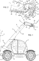
Figure 1 is a lateral view of a telehandler according to the present invention comprising a boom and a handling system attached thereto; -
Figure 2 is a partial perspective view of the boom and the handling system offigure 1 in an enlarged scale; -
Figures 3 and 4 are lateral views of a portion of the boom and the handling system offigures 1 and 2 in a further enlarged scale in two respective operative positions; -
Figures 5 and 6 are perspective view of a component of the handling system ofFigures 1 to 4 ; and -
Figure 7 is a partial perspective view of the boom and the handling system ofFigures 1 to 4 . - With reference to
figure 1 ,numeral 1 indicates a telehandler, in particular for industrial or agricultural applications. - Telehandler 1 comprises a frame 2 and a plurality of
wheels 3 for moving the frame 2 with respect to the ground. In addition,telehandler 1 is preferably provided with a driver's cockpit 4. - Telehandler 1 further comprises a
boom 5, which is fitted in a movable manner to frame 2. In particular,boom 5 is a telescopic boom, i.e. extendable or retractable along a direction A. Furthermore,boom 5 may be rotatable about a vertical axis Z and/or a horizontal axis Y of telehandler 1 (figure 1 ). - In detail,
boom 5 comprises afirst end 5a, at which it is articulated on frame 2 and asecond end 5b, which is opposite tofirst end 5a and adapted to be operatively connected with a not-shown operative tool oftelehandler 1, such as a bucket, pallet forks or a winch. - In the embodiment shown,
boom 5 comprises afirst stretch 50 on the side offirst end 5a and asecond stretch 51 on the side ofsecond end 5b. In detail,second stretch 51 is hinged to firststretch 50 and is rotatable with respect tofirst stretch 50 about an axis W transversal to direction A. In further detail, whensecond stretch 51 is in the default position illustrated infigure 1 , it extends along a direction J that is transversal to direction A. - As shown in
figure 1 ,telehandler 1 comprises ahandling system 10, which is arranged atsecond end 5b. More precisely, handlingsystem 10 is arranged atsecond stretch 51. -
Handling system 10 comprises, in turn, acylinder 11, astem 12 sliding withincylinder 11 along a direction B and alever 13 operatively connected tostem 12. In detail,cylinder 11 may be a hydraulic or a pneumatic cylinder. - As shown in
figure 7 ,second stretch 51 is at least partially hollow and defines acavity 52. Preferably,cylinder 11 andstem 12 are completely housed insidecavity 52. In addition,lever 13 is at least partially housed insidecavity 52. -
Stem 12 is slidable between an extended position and a retracted position with respect tocylinder 11. In detail,stem 12 comprises a not-shown inner end, which is arranged insidecylinder 11 and an outer end, which is opposite to the inner end and is arranged outsidecylinder 11. Whenstem 12 is in the extended position, the outer end ofstem 12 is placed at a first distance with respect to cylinder 11 (figure 3 ); whenstem 12 is in the retracted position, the outer end ofstem 12 is placed at a second distance with respect to cylinder 11 (figure 4 ). In detail, the second distance is smaller than the first distance. -
Lever 13 is rotatable about an axis C transversal to direction B as a consequence of the movement ofstem 12 within cylinder 11 (figures 3 and 4 ). In other words,lever 13 is adapted to convert the translation ofstem 12 withincylinder 11 into a rotational movement. -
Handling system 10 further comprises alocking element 14, which is hinged to boom 5 and is operatively connected tolever 13.Locking element 14 is rotatable about an axis D, which is parallel to axis C. - In particular,
locking element 14 may be directly or indirectly operatively connected tolever 13. In other words, one or more elements may be interposed betweenlever 13 and lockingelement 14 without preventinglever 13 and connectingelement 14 from being operatively connected to each other. - Furthermore,
boom 5 comprises twostop portions 15, 16, which are adapted to limit the rotation oflocking element 14 about axis D. - Advantageously,
locking element 14 is rotatable between a first angular position, in which it is adapted to cooperate withstop portion 15 and to lockstem 12 in the extended position (figure 3 ) and a second angular position, in which it is adapted to cooperate with stop portion 16 and to lockstem 12 in the retracted position (figure 4 ). - Since
locking element 14 is operatively connected tolever 13 and sincelever 13 is adapted to rotate as a consequence of the movement ofstem 12 withincylinder 11, the rotation oflocking element 14 is determined by the movement ofstem 12 withincylinder 11. In particular, each position ofstem 12 withincylinder 11 between the extended and the retracted positions corresponds to an angular position oflocking element 14 between the first and the second angular positions. - In detail,
locking element 14 is adapted tocontact stop portion 15 in the first angular position and to contact stop portion 16 in the second angular position. In further detail,stop portion 15 is adapted to prevent the rotation oflocking element 14 beyond the first angular position in the rotational direction oriented from the second angular position to the first angular position. Similarly, stop portion 16 is adapted to prevent the rotation oflocking element 14 beyond the second angular position in the rotational direction oriented from the first angular position to the second angular position. - Preferably,
locking element 14 is rotatable between the first angular position and the second angular position by an angle of 135° about axis D. - As shown in
figures 3 and 4 , handlingsystem 10 further comprises a connectingelement 17, which is operatively connected tolever 13 and to lockingelement 14. In particular, connectingelement 17 is adapted to transmit to lockingelement 14 the rotation oflever 13 about axis C. - Furthermore, as shown in
figures 3 and 4 ,lever 13 comprises acentral portion 13a, afirst arm 13b and asecond arm 13c. In detail, first andsecond arms central portion 13a along two respective directions F, G transversal to each other. In other words,lever 13 is substantially V-shaped or boomerang-shaped. - More precisely,
central portion 13a, first andsecond arms first arm 13a andsecond arm 13b are rounded to each other. -
Lever 13 is hinged to the outer end ofstem 12 atcentral portion 13a; it is hinged toboom 5 atfirst arm 13b with ahinge 80 and it is hinged to connectingelement 17 atsecond arm 13c. - In detail, hinge 80 is a fixed hinge and comprises a
pin 81 defining axis C. In further detail, pin 81 protrudes fromsecond stretch 51 and out ofcavity 52 parallel to axis C (figure 2 ) . - As shown in
figures 3 and 4 , the extension offirst arm 13b along direction F is greater than the extension ofsecond arm 13c along direction G. In addition, the distance between the point at whichcentral portion 13a is hinged to stem 12 and hinge 80 is greater than the distance between the point at whichcentral portion 13a is hinged to stem 12 and the point at whichsecond arm 13c is hinged to connectingelement 17. - In the embodiment shown, proceeding along
first arm 13b along direction F and away fromcentral portion 13c, the extension offirst arm 13b perpendicularly to direction F progressively decreases and then progressively increases. On the other hand, proceeding alongsecond arm 13c along direction G and away fromcentral portion 13a, the extension ofsecond arm 13c perpendicularly to direction G progressively decreases. - As shown in detail in
figures 5 and 6 , lockingelement 14 comprises amain portion 20 and twoflange portions 21. - In detail,
main portion 20 comprises acentral portion 20a and twolateral portions 20b, which extend fromcentral portion 20a at two respective opposite ends thereof along a direction E of lockingelement 14. In further detail,central portions 20a andlateral portions 20b are planar and rounded to one another. In addition,lateral portions 20b are perpendicular tocentral portion 20a. In other words,main portion 20 is U-shaped. - In particular, when locking
element 14 is fitted toboom 5, direction E and axis D are parallel to each other. - Each
lateral portion 20b comprises, in turn, anabutment portion 24, which is adapted to abut against second stop portion 16 when lockingelement 14 is in the second angular position (figures 4 and7 ). In detail, eachabutment portion 24 is planar and is arranged at the end of the respectivelateral portion 20b opposite tocentral portion 20a. -
Flange portions 21 extend fromcentral portion 20a on the same side oflateral portions 20b and are interposed betweenlateral portions 20b along direction E. In addition,flange portions 21 are spaced from each other along direction E and are identical to each other. Preferably,flange portions 21 are arranged symmetrically with respect to a median plane ofmain portion 20 along direction E. - As shown in
figures 3 and 4 ,main portion 20 is hinged toboom 5 andflange portions 21 are hinged to connectingelement 17. - In detail,
main portion 20 is formed with twoholes 22 through which lockingelement 14 is hinged toboom 5. In further detail, eachlateral portion 20b is formed with arespective hole 22. As illustrated infigures 5 and 6 , holes 22 are through and concentric holes. - In addition, each
flange portion 21 is formed with arespective hole 23, through which lockingelement 14 is hinged to connectingelement 17. As illustrated infigures 5 and 6 , holes 23 are through and concentric holes. - Furthermore, as shown in
figures 3 and 4 , connectingelement 17 is substantially a rod comprising afirst end 17a and asecond end 17b, which are opposite to each other. In detail,first end 17a is hinged tosecond arm 13c oflever 13 andsecond end 17b is hinged toflange portions 21 throughholes 23. - As illustrated in
figure 7 , lockingelement 14 is fitted toboom 5 in such a manner thatmain portion 20 andflange portions 21face boom 5 and define aseat 55 with respect tosecond end 5b. More precisely,central portion 20a facesboom 5 on the side from whichlateral portions 20b andflange portions 21 extend. In addition,main portion 20 is arranged completely external with respect tocavity 52. - More precisely,
seat 55 is delimited bycentral portion 20a on the side from whichlateral portions 20b andflange portions 21 extend.Seat 55 is further delimited bylateral portions 20b on the side offlange portions 21 andsecond end 5b ofboom 5. - Furthermore, stop
portions 15 and 16 can be variously conformed for the purpose of limiting the rotation of lockingelement 14 between the first and the second angular positions. - In the embodiment shown, stop
portion 15 compriseshinge 80, which acts as a detent. In detail, the portion ofhinge 80 arranged externally with respect tocavity 52 is adapted to act as an abutment for lockingelement 14, when lockingelement 14 is in the first angular position (figure 3 ). In further detail, such portion ofhinge 80 is adapted to abut againstlateral portions 20b of lockingelement 14. - Alternatively or in addition,
stop portion 15 comprises a portion ofend 5b ofboom 5. In detail, when lockingelement 14 is in the first angular position, lockingelement 14 abuts againstend 5b. In further detail,flange portions 21 are adapted to contactend 5b, when lockingelement 14 is in the first angular position (figure 3 ). - Stop portion 16 comprises a detent 53 arranged at
second stretch 51 and extending transversally to direction J towards the outside ofsecond stretch 51. Detent 53 is completely external with respect tocavity 52 and comprises an abutment portion 54 (figure 3 ). In detail, abutment portion 54 is adapted to contactabutment portion 24 of lockingelement 14 when lockingelement 14 is in the second angular position (figures 4 and7 ) . - The operation of the locking
element 14 according to the invention and described as above is the following. In particular, the operation will be described starting from a condition in which lockingelement 14 is in the first angular position (figure 3 ). - In this condition, stem 12 is in the extended position and locking
element 14 abuts againstfirst stop portion 15. In particular,lateral portions 20b abut againsthinge 80 and/orflange portions 21 abut against a portion ofend 5b. - Therefore, the rotation of locking
element 14 beyond the first angular position in the rotational direction oriented from the second angular position to the first angular position is prevented. - When it is necessary to operate the operative tools fitted to
boom 5, stem 12 moves from the extended position toward the retracted position and the outer end ofstem 12 moves closer tocylinder 11 along direction B. Accordingly,lever 13, which is hinged to stem 12 rotates about axis C. In detail, with reference tofigure 3 ,lever 13 rotates clockwise about axis C. - As a consequence of the rotation of
lever 13 and because of the fact that lockingelement 14 is operatively connected to lever 13 through connectingelement 17, lockingelement 14 rotates about axis D toward the second angular position. - When stem 12 reaches the retracted position, locking
element 14 is in the second angular position. In this condition, lockingelement 14 abuts against second stop portion 16. In detail,abutment portion 24 of lockingelement 14 abuts against abutment portion 54 of detent 53 (figures 4 and7 ). - Therefore, the rotation of locking
element 14 beyond the second angular position in the rotational direction oriented from the first angular position to the second angular position is prevented. - In view of the foregoing, the advantages of handling
system 10, ofboom 5 andtelehandler 1 according to the invention are apparent. - In particular, handling
system 10 comprises lockingelement 14, which is rotatable between the first angular position, in which it is adapted to lockstem 12 in the extended position and the second angular position, in which it is adapted to lockstem 12 in the retracted position. - Accordingly, the risk of damage to the mechanical parts of
boom 5 is minimized. In fact, since the rotation of lockingelement 14 beyond the first angular position in the rotational direction from the second angular position to the first angular position is prevented, stem 12 cannot slip beyond the extended position and away fromcylinder 11. The risk of damages is reduced also whenboom 5 and the operative tools attached thereto are subjected to high loads. - It is clear that modifications can be made to the described
handling system 10 which do not extend beyond the scope of protection defined by the claims. - For the sake of example, handling
system 10 could comprise more than onelever 13 and/or more than one connectingelement 17. In addition,lever 13, connectingelement 17 and lockingelement 14 could be differently shaped.
Claims (10)
- Handling system for a boom (5) of a telehandler (1) comprising:- a cylinder (11) and a stem (12) adapted to slide within said cylinder (11) along a first direction (B);- a lever (13) operatively connected to said stem (12) and adapted to rotate about a first axis (C) as a result of the sliding of said stem (12) within said cylinder (11); said first axis (C) being transversal to said first direction (B); and- a locking element (14), which is hinged to said boom (5) and is operatively connected to said lever (13); said locking element (14) being rotatable about a second axis (D) parallel to said first axis (C);wherein said locking element (14) is rotatable between:- a first angular position, in which it is adapted to cooperate with a first stop portion (15) of said boom (5) and to lock said stem (12) in an extended position with respect to said cylinder (11); and- a second angular position different than the first angular position, in which it is adapted to cooperate with a second stop portion (16) of said boom (5) and to lock said stem (12) in a retracted position with respect to said cylinder (11) .
- Handling system according to claim 1, further comprising a connecting element (17), which is operatively connected to said lever (13) and said locking element (14); said connecting element (17) being adapted to transmit to said locking element (14) the rotation of said lever (13) about said first axis (C).
- Handling system according to claim 2, wherein said lever (13) is hinged to said stem (12), to said boom (5) and to said connecting element (17).
- Handling system according to claims 2 or 3, wherein said locking element (14) comprises:- a main portion (20) through which it is adapted to be hinged to said boom (5); and- at least one flange portion (21) extending from said main portion (20) and through which it is hinged to said connecting element (17).
- Handling system according to claim 4, wherein said locking element (14) is adapted to be fitted to said boom (5) in such a manner that said main portion (20) and said at least one flange portion (21) are adapted to face said boom (5) and to define a seat (55) with respect to said boom (5).
- Handling system according to any one of the foregoing claims, wherein said locking element (14) is rotatable between said first angular position and said second angular position by an angle of 135° about second axis (D).
- Boom for a telehandler (1) comprising:- a first end (5a) at which said boom (5) is adapted to be articulated on said telehandler (1);- a second end (5b), which is opposite to said first end (5a) and adapted to be operatively connected with an operative tool of said telehandler (1); and- a handling system (10) according to any one of the foregoing claims; said handling system (10) being arranged at said second end (5b).
- Boom according to claim 7, further comprising:- a first stop portion (15), against which a locking element (14) of said handling system (10) is adapted to abut when said locking element (14) is in a first angular position; and- a second stop portion (16), against which said locking element (14) is adapted to abut when said locking element (14) is in a second angular position that is different than the first angular position.
- Boom according to claim 8, wherein said first stop portion (15) and/or said second stop portion (16) is a detent (53; 80) or a portion of said second end (5b).
- Telehandler comprising:- a frame (2);- traction means (3) adapted to move said frame (2) with respect to the ground; and- a boom (5) according to any one of claims 7 to 9.
Applications Claiming Priority (1)
| Application Number | Priority Date | Filing Date | Title |
|---|---|---|---|
| IT102021000006818A IT202100006818A1 (en) | 2021-03-22 | 2021-03-22 | HANDLING SYSTEM, ARM FOR A TELEHANDLER (TELEHANDLER) AND TELEHANDLER INCLUDING THIS ARM |
Publications (2)
| Publication Number | Publication Date |
|---|---|
| EP4063572A1 true EP4063572A1 (en) | 2022-09-28 |
| EP4063572B1 EP4063572B1 (en) | 2025-09-03 |
Family
ID=75937125
Family Applications (1)
| Application Number | Title | Priority Date | Filing Date |
|---|---|---|---|
| EP22163225.0A Active EP4063572B1 (en) | 2021-03-22 | 2022-03-21 | Handling system, boom for a telehandler and telehandler comprising such boom |
Country Status (2)
| Country | Link |
|---|---|
| EP (1) | EP4063572B1 (en) |
| IT (1) | IT202100006818A1 (en) |
Cited By (1)
| Publication number | Priority date | Publication date | Assignee | Title |
|---|---|---|---|---|
| CN116621084A (en) * | 2023-06-26 | 2023-08-22 | 湖南中联重科智能高空作业机械有限公司 | Work attachment attachments and telehandlers |
Citations (4)
| Publication number | Priority date | Publication date | Assignee | Title |
|---|---|---|---|---|
| US20060180563A1 (en) * | 2004-07-22 | 2006-08-17 | J.C. Bamford Excavators Limited | Method of operating a machine |
| US20080295679A1 (en) * | 2007-05-18 | 2008-12-04 | Caterpillar Inc | Controlled motion in a hydraulically actuated system |
| US9238903B2 (en) * | 2009-03-26 | 2016-01-19 | Komatsu Ltd. | Control method and control apparatus for work vehicle |
| US9719231B2 (en) * | 2014-05-20 | 2017-08-01 | Caterpillar Inc. | Implement system for machine |
-
2021
- 2021-03-22 IT IT102021000006818A patent/IT202100006818A1/en unknown
-
2022
- 2022-03-21 EP EP22163225.0A patent/EP4063572B1/en active Active
Patent Citations (4)
| Publication number | Priority date | Publication date | Assignee | Title |
|---|---|---|---|---|
| US20060180563A1 (en) * | 2004-07-22 | 2006-08-17 | J.C. Bamford Excavators Limited | Method of operating a machine |
| US20080295679A1 (en) * | 2007-05-18 | 2008-12-04 | Caterpillar Inc | Controlled motion in a hydraulically actuated system |
| US9238903B2 (en) * | 2009-03-26 | 2016-01-19 | Komatsu Ltd. | Control method and control apparatus for work vehicle |
| US9719231B2 (en) * | 2014-05-20 | 2017-08-01 | Caterpillar Inc. | Implement system for machine |
Cited By (1)
| Publication number | Priority date | Publication date | Assignee | Title |
|---|---|---|---|---|
| CN116621084A (en) * | 2023-06-26 | 2023-08-22 | 湖南中联重科智能高空作业机械有限公司 | Work attachment attachments and telehandlers |
Also Published As
| Publication number | Publication date |
|---|---|
| IT202100006818A1 (en) | 2022-09-22 |
| EP4063572B1 (en) | 2025-09-03 |
Similar Documents
| Publication | Publication Date | Title |
|---|---|---|
| FI124870B (en) | boom system | |
| US11358843B2 (en) | Retracting carriage attachment | |
| EP4063572B1 (en) | Handling system, boom for a telehandler and telehandler comprising such boom | |
| US11661319B2 (en) | Dual actuator assembly | |
| US20100166531A1 (en) | Tire manipulator and personnel safety device | |
| US8113363B2 (en) | Adjusting mechanism for a winch | |
| AU2015417849B2 (en) | Grapple | |
| US20180333987A1 (en) | Working Machine | |
| US12264450B2 (en) | Robust multi-tool assembly for hydraulic excavators | |
| EP3691986B1 (en) | Grapple | |
| US10774498B2 (en) | Robust multi-tool assembly for hydraulic excavators | |
| EP3114073B1 (en) | Equipment attaching device for vehicles | |
| CA2702707C (en) | Crane with a second drive | |
| EP3532424B1 (en) | Foldable crane | |
| KR200458795Y1 (en) | Tongs for carrying mast of forklift | |
| US3709390A (en) | Heel boom construction | |
| EP1443013B1 (en) | Lift truck with telescopic arm | |
| US10815634B2 (en) | Loader attachments coupler | |
| EP4640616A1 (en) | Telescopic boom of a crane | |
| US10106377B1 (en) | Lifting tool | |
| EP3524564B1 (en) | A crane for moving loads | |
| IT202300015045A1 (en) | IMPROVED LIMIT SWITCH MECHANISM FOR A WORK VEHICLE | |
| AU2022247143A1 (en) | Crane | |
| KR100402329B1 (en) | Device for locking attachment coupler of industrial vehicle | |
| AU2019202654A1 (en) | Shaft Handler Attachment |
Legal Events
| Date | Code | Title | Description |
|---|---|---|---|
| PUAI | Public reference made under article 153(3) epc to a published international application that has entered the european phase |
Free format text: ORIGINAL CODE: 0009012 |
|
| STAA | Information on the status of an ep patent application or granted ep patent |
Free format text: STATUS: THE APPLICATION HAS BEEN PUBLISHED |
|
| AK | Designated contracting states |
Kind code of ref document: A1 Designated state(s): AL AT BE BG CH CY CZ DE DK EE ES FI FR GB GR HR HU IE IS IT LI LT LU LV MC MK MT NL NO PL PT RO RS SE SI SK SM TR |
|
| STAA | Information on the status of an ep patent application or granted ep patent |
Free format text: STATUS: REQUEST FOR EXAMINATION WAS MADE |
|
| 17P | Request for examination filed |
Effective date: 20230328 |
|
| RBV | Designated contracting states (corrected) |
Designated state(s): AL AT BE BG CH CY CZ DE DK EE ES FI FR GB GR HR HU IE IS IT LI LT LU LV MC MK MT NL NO PL PT RO RS SE SI SK SM TR |
|
| RAP3 | Party data changed (applicant data changed or rights of an application transferred) |
Owner name: CNH INDUSTRIAL ITALIA S.P.A. |
|
| GRAP | Despatch of communication of intention to grant a patent |
Free format text: ORIGINAL CODE: EPIDOSNIGR1 |
|
| STAA | Information on the status of an ep patent application or granted ep patent |
Free format text: STATUS: GRANT OF PATENT IS INTENDED |
|
| RIC1 | Information provided on ipc code assigned before grant |
Ipc: E02F 9/14 20060101ALI20250331BHEP Ipc: E02F 3/96 20060101ALI20250331BHEP Ipc: B66F 9/065 20060101ALI20250331BHEP Ipc: E02F 3/36 20060101ALI20250331BHEP Ipc: E02F 9/22 20060101AFI20250331BHEP |
|
| INTG | Intention to grant announced |
Effective date: 20250416 |
|
| GRAS | Grant fee paid |
Free format text: ORIGINAL CODE: EPIDOSNIGR3 |
|
| GRAA | (expected) grant |
Free format text: ORIGINAL CODE: 0009210 |
|
| STAA | Information on the status of an ep patent application or granted ep patent |
Free format text: STATUS: THE PATENT HAS BEEN GRANTED |
|
| AK | Designated contracting states |
Kind code of ref document: B1 Designated state(s): AL AT BE BG CH CY CZ DE DK EE ES FI FR GB GR HR HU IE IS IT LI LT LU LV MC MK MT NL NO PL PT RO RS SE SI SK SM TR |
|
| REG | Reference to a national code |
Ref country code: CH Ref legal event code: EP |
|
| REG | Reference to a national code |
Ref country code: DE Ref legal event code: R096 Ref document number: 602022020535 Country of ref document: DE |
|
| REG | Reference to a national code |
Ref country code: IE Ref legal event code: FG4D |
|
| REG | Reference to a national code |
Ref country code: NL Ref legal event code: MP Effective date: 20250903 |
|
| PG25 | Lapsed in a contracting state [announced via postgrant information from national office to epo] |
Ref country code: NO Free format text: LAPSE BECAUSE OF FAILURE TO SUBMIT A TRANSLATION OF THE DESCRIPTION OR TO PAY THE FEE WITHIN THE PRESCRIBED TIME-LIMIT Effective date: 20251203 |
|
| REG | Reference to a national code |
Ref country code: LT Ref legal event code: MG9D |
|
| PG25 | Lapsed in a contracting state [announced via postgrant information from national office to epo] |
Ref country code: FI Free format text: LAPSE BECAUSE OF FAILURE TO SUBMIT A TRANSLATION OF THE DESCRIPTION OR TO PAY THE FEE WITHIN THE PRESCRIBED TIME-LIMIT Effective date: 20250903 |
|
| PG25 | Lapsed in a contracting state [announced via postgrant information from national office to epo] |
Ref country code: HR Free format text: LAPSE BECAUSE OF FAILURE TO SUBMIT A TRANSLATION OF THE DESCRIPTION OR TO PAY THE FEE WITHIN THE PRESCRIBED TIME-LIMIT Effective date: 20250903 |
|
| PG25 | Lapsed in a contracting state [announced via postgrant information from national office to epo] |
Ref country code: GR Free format text: LAPSE BECAUSE OF FAILURE TO SUBMIT A TRANSLATION OF THE DESCRIPTION OR TO PAY THE FEE WITHIN THE PRESCRIBED TIME-LIMIT Effective date: 20251204 |
|
| PG25 | Lapsed in a contracting state [announced via postgrant information from national office to epo] |
Ref country code: SE Free format text: LAPSE BECAUSE OF FAILURE TO SUBMIT A TRANSLATION OF THE DESCRIPTION OR TO PAY THE FEE WITHIN THE PRESCRIBED TIME-LIMIT Effective date: 20250903 |
|
| PG25 | Lapsed in a contracting state [announced via postgrant information from national office to epo] |
Ref country code: LV Free format text: LAPSE BECAUSE OF FAILURE TO SUBMIT A TRANSLATION OF THE DESCRIPTION OR TO PAY THE FEE WITHIN THE PRESCRIBED TIME-LIMIT Effective date: 20250903 |
|
| PG25 | Lapsed in a contracting state [announced via postgrant information from national office to epo] |
Ref country code: BG Free format text: LAPSE BECAUSE OF FAILURE TO SUBMIT A TRANSLATION OF THE DESCRIPTION OR TO PAY THE FEE WITHIN THE PRESCRIBED TIME-LIMIT Effective date: 20250903 Ref country code: PL Free format text: LAPSE BECAUSE OF FAILURE TO SUBMIT A TRANSLATION OF THE DESCRIPTION OR TO PAY THE FEE WITHIN THE PRESCRIBED TIME-LIMIT Effective date: 20250903 |
|
| PG25 | Lapsed in a contracting state [announced via postgrant information from national office to epo] |
Ref country code: RS Free format text: LAPSE BECAUSE OF FAILURE TO SUBMIT A TRANSLATION OF THE DESCRIPTION OR TO PAY THE FEE WITHIN THE PRESCRIBED TIME-LIMIT Effective date: 20251203 |
|
| PG25 | Lapsed in a contracting state [announced via postgrant information from national office to epo] |
Ref country code: ES Free format text: LAPSE BECAUSE OF FAILURE TO SUBMIT A TRANSLATION OF THE DESCRIPTION OR TO PAY THE FEE WITHIN THE PRESCRIBED TIME-LIMIT Effective date: 20250903 |
|
| REG | Reference to a national code |
Ref country code: AT Ref legal event code: MK05 Ref document number: 1833196 Country of ref document: AT Kind code of ref document: T Effective date: 20250903 |
|
| PG25 | Lapsed in a contracting state [announced via postgrant information from national office to epo] |
Ref country code: NL Free format text: LAPSE BECAUSE OF FAILURE TO SUBMIT A TRANSLATION OF THE DESCRIPTION OR TO PAY THE FEE WITHIN THE PRESCRIBED TIME-LIMIT Effective date: 20250903 |
|
| PG25 | Lapsed in a contracting state [announced via postgrant information from national office to epo] |
Ref country code: SM Free format text: LAPSE BECAUSE OF FAILURE TO SUBMIT A TRANSLATION OF THE DESCRIPTION OR TO PAY THE FEE WITHIN THE PRESCRIBED TIME-LIMIT Effective date: 20250903 |
|
| PGFP | Annual fee paid to national office [announced via postgrant information from national office to epo] |
Ref country code: GB Payment date: 20260319 Year of fee payment: 5 |
|
| PGFP | Annual fee paid to national office [announced via postgrant information from national office to epo] |
Ref country code: DE Payment date: 20260320 Year of fee payment: 5 |
|
| PG25 | Lapsed in a contracting state [announced via postgrant information from national office to epo] |
Ref country code: AT Free format text: LAPSE BECAUSE OF FAILURE TO SUBMIT A TRANSLATION OF THE DESCRIPTION OR TO PAY THE FEE WITHIN THE PRESCRIBED TIME-LIMIT Effective date: 20250903 |
|
| PGFP | Annual fee paid to national office [announced via postgrant information from national office to epo] |
Ref country code: IT Payment date: 20260320 Year of fee payment: 5 |
|
| PG25 | Lapsed in a contracting state [announced via postgrant information from national office to epo] |
Ref country code: IS Free format text: LAPSE BECAUSE OF FAILURE TO SUBMIT A TRANSLATION OF THE DESCRIPTION OR TO PAY THE FEE WITHIN THE PRESCRIBED TIME-LIMIT Effective date: 20260103 |
|
| PGFP | Annual fee paid to national office [announced via postgrant information from national office to epo] |
Ref country code: FR Payment date: 20260323 Year of fee payment: 5 |
|
| PG25 | Lapsed in a contracting state [announced via postgrant information from national office to epo] |
Ref country code: PT Free format text: LAPSE BECAUSE OF FAILURE TO SUBMIT A TRANSLATION OF THE DESCRIPTION OR TO PAY THE FEE WITHIN THE PRESCRIBED TIME-LIMIT Effective date: 20260105 Ref country code: CZ Free format text: LAPSE BECAUSE OF FAILURE TO SUBMIT A TRANSLATION OF THE DESCRIPTION OR TO PAY THE FEE WITHIN THE PRESCRIBED TIME-LIMIT Effective date: 20250903 |
|
| PG25 | Lapsed in a contracting state [announced via postgrant information from national office to epo] |
Ref country code: SK Free format text: LAPSE BECAUSE OF FAILURE TO SUBMIT A TRANSLATION OF THE DESCRIPTION OR TO PAY THE FEE WITHIN THE PRESCRIBED TIME-LIMIT Effective date: 20250903 Ref country code: EE Free format text: LAPSE BECAUSE OF FAILURE TO SUBMIT A TRANSLATION OF THE DESCRIPTION OR TO PAY THE FEE WITHIN THE PRESCRIBED TIME-LIMIT Effective date: 20250903 |
|
| REG | Reference to a national code |
Ref country code: DE Ref legal event code: R097 Ref document number: 602022020535 Country of ref document: DE |
|
| PG25 | Lapsed in a contracting state [announced via postgrant information from national office to epo] |
Ref country code: LT Free format text: LAPSE BECAUSE OF FAILURE TO SUBMIT A TRANSLATION OF THE DESCRIPTION OR TO PAY THE FEE WITHIN THE PRESCRIBED TIME-LIMIT Effective date: 20250903 |
|
| PG25 | Lapsed in a contracting state [announced via postgrant information from national office to epo] |
Ref country code: DK Free format text: LAPSE BECAUSE OF FAILURE TO SUBMIT A TRANSLATION OF THE DESCRIPTION OR TO PAY THE FEE WITHIN THE PRESCRIBED TIME-LIMIT Effective date: 20250903 |
|
| PLBE | No opposition filed within time limit |
Free format text: ORIGINAL CODE: 0009261 |
|
| STAA | Information on the status of an ep patent application or granted ep patent |
Free format text: STATUS: NO OPPOSITION FILED WITHIN TIME LIMIT |
|
| REG | Reference to a national code |
Ref country code: CH Ref legal event code: L10 Free format text: ST27 STATUS EVENT CODE: U-0-0-L10-L00 (AS PROVIDED BY THE NATIONAL OFFICE) Effective date: 20260715 |
|
| 26N | No opposition filed |
Effective date: 20260604 |