EP4063524A1 - Method for producing carbon monoxide and use thereof - Google Patents
Method for producing carbon monoxide and use thereof Download PDFInfo
- Publication number
- EP4063524A1 EP4063524A1 EP20889482.4A EP20889482A EP4063524A1 EP 4063524 A1 EP4063524 A1 EP 4063524A1 EP 20889482 A EP20889482 A EP 20889482A EP 4063524 A1 EP4063524 A1 EP 4063524A1
- Authority
- EP
- European Patent Office
- Prior art keywords
- carbon
- carbon dioxide
- gas
- product
- blast furnace
- Prior art date
- Legal status (The legal status is an assumption and is not a legal conclusion. Google has not performed a legal analysis and makes no representation as to the accuracy of the status listed.)
- Pending
Links
- UGFAIRIUMAVXCW-UHFFFAOYSA-N Carbon monoxide Chemical compound [O+]#[C-] UGFAIRIUMAVXCW-UHFFFAOYSA-N 0.000 title claims abstract description 134
- 229910002091 carbon monoxide Inorganic materials 0.000 title claims abstract description 134
- 238000004519 manufacturing process Methods 0.000 title abstract description 9
- CURLTUGMZLYLDI-UHFFFAOYSA-N Carbon dioxide Chemical compound O=C=O CURLTUGMZLYLDI-UHFFFAOYSA-N 0.000 claims abstract description 196
- XEEYBQQBJWHFJM-UHFFFAOYSA-N Iron Chemical compound [Fe] XEEYBQQBJWHFJM-UHFFFAOYSA-N 0.000 claims abstract description 140
- 229910002092 carbon dioxide Inorganic materials 0.000 claims abstract description 105
- 239000001569 carbon dioxide Substances 0.000 claims abstract description 105
- 239000006227 byproduct Substances 0.000 claims abstract description 73
- 229910052742 iron Inorganic materials 0.000 claims abstract description 70
- OKTJSMMVPCPJKN-UHFFFAOYSA-N Carbon Chemical compound [C] OKTJSMMVPCPJKN-UHFFFAOYSA-N 0.000 claims abstract description 54
- 229910052799 carbon Inorganic materials 0.000 claims abstract description 54
- 238000002407 reforming Methods 0.000 claims abstract description 48
- 239000000203 mixture Substances 0.000 claims abstract description 5
- 238000006243 chemical reaction Methods 0.000 claims description 66
- 239000000155 melt Substances 0.000 claims description 36
- 238000000034 method Methods 0.000 claims description 30
- 238000007664 blowing Methods 0.000 claims description 28
- 239000003245 coal Substances 0.000 claims description 18
- 238000004064 recycling Methods 0.000 abstract description 2
- 239000007789 gas Substances 0.000 description 91
- 239000003638 chemical reducing agent Substances 0.000 description 11
- 230000000694 effects Effects 0.000 description 10
- 238000010586 diagram Methods 0.000 description 8
- 229910000831 Steel Inorganic materials 0.000 description 7
- 238000005516 engineering process Methods 0.000 description 7
- 239000010959 steel Substances 0.000 description 7
- 230000000052 comparative effect Effects 0.000 description 6
- UFHFLCQGNIYNRP-UHFFFAOYSA-N Hydrogen Chemical compound [H][H] UFHFLCQGNIYNRP-UHFFFAOYSA-N 0.000 description 5
- QVGXLLKOCUKJST-UHFFFAOYSA-N atomic oxygen Chemical compound [O] QVGXLLKOCUKJST-UHFFFAOYSA-N 0.000 description 5
- 239000000571 coke Substances 0.000 description 5
- 239000001301 oxygen Substances 0.000 description 5
- 229910052760 oxygen Inorganic materials 0.000 description 5
- 238000006722 reduction reaction Methods 0.000 description 5
- 239000001257 hydrogen Substances 0.000 description 4
- 229910052739 hydrogen Inorganic materials 0.000 description 4
- QGZKDVFQNNGYKY-UHFFFAOYSA-N Ammonia Chemical compound N QGZKDVFQNNGYKY-UHFFFAOYSA-N 0.000 description 2
- 239000003054 catalyst Substances 0.000 description 2
- 239000000463 material Substances 0.000 description 2
- 239000012621 metal-organic framework Substances 0.000 description 2
- 238000011084 recovery Methods 0.000 description 2
- 238000011946 reduction process Methods 0.000 description 2
- 238000000926 separation method Methods 0.000 description 2
- WFKWXMTUELFFGS-UHFFFAOYSA-N tungsten Chemical compound [W] WFKWXMTUELFFGS-UHFFFAOYSA-N 0.000 description 2
- 229910052721 tungsten Inorganic materials 0.000 description 2
- 239000010937 tungsten Substances 0.000 description 2
- 238000010744 Boudouard reaction Methods 0.000 description 1
- 235000019738 Limestone Nutrition 0.000 description 1
- ZOKXTWBITQBERF-UHFFFAOYSA-N Molybdenum Chemical compound [Mo] ZOKXTWBITQBERF-UHFFFAOYSA-N 0.000 description 1
- 238000003723 Smelting Methods 0.000 description 1
- 238000010521 absorption reaction Methods 0.000 description 1
- 239000003463 adsorbent Substances 0.000 description 1
- 150000001412 amines Chemical class 0.000 description 1
- 229910021529 ammonia Inorganic materials 0.000 description 1
- 150000001721 carbon Chemical class 0.000 description 1
- 238000004939 coking Methods 0.000 description 1
- 238000001816 cooling Methods 0.000 description 1
- PMHQVHHXPFUNSP-UHFFFAOYSA-M copper(1+);methylsulfanylmethane;bromide Chemical compound Br[Cu].CSC PMHQVHHXPFUNSP-UHFFFAOYSA-M 0.000 description 1
- 230000003247 decreasing effect Effects 0.000 description 1
- 238000001035 drying Methods 0.000 description 1
- 230000007613 environmental effect Effects 0.000 description 1
- 238000002474 experimental method Methods 0.000 description 1
- 239000000446 fuel Substances 0.000 description 1
- 239000006028 limestone Substances 0.000 description 1
- 239000007788 liquid Substances 0.000 description 1
- 238000005259 measurement Methods 0.000 description 1
- 239000012528 membrane Substances 0.000 description 1
- 229910052750 molybdenum Inorganic materials 0.000 description 1
- 239000011733 molybdenum Substances 0.000 description 1
- 239000000047 product Substances 0.000 description 1
- 230000035484 reaction time Effects 0.000 description 1
- 238000006057 reforming reaction Methods 0.000 description 1
- HBMJWWWQQXIZIP-UHFFFAOYSA-N silicon carbide Chemical compound [Si+]#[C-] HBMJWWWQQXIZIP-UHFFFAOYSA-N 0.000 description 1
- 229910010271 silicon carbide Inorganic materials 0.000 description 1
- 238000001179 sorption measurement Methods 0.000 description 1
- 238000009628 steelmaking Methods 0.000 description 1
- 238000009423 ventilation Methods 0.000 description 1
Images



Classifications
-
- C—CHEMISTRY; METALLURGY
- C21—METALLURGY OF IRON
- C21B—MANUFACTURE OF IRON OR STEEL
- C21B5/00—Making pig-iron in the blast furnace
- C21B5/06—Making pig-iron in the blast furnace using top gas in the blast furnace process
-
- C—CHEMISTRY; METALLURGY
- C21—METALLURGY OF IRON
- C21B—MANUFACTURE OF IRON OR STEEL
- C21B7/00—Blast furnaces
- C21B7/002—Evacuating and treating of exhaust gases
-
- C—CHEMISTRY; METALLURGY
- C21—METALLURGY OF IRON
- C21B—MANUFACTURE OF IRON OR STEEL
- C21B7/00—Blast furnaces
- C21B7/007—Controlling or regulating of the top pressure
-
- C—CHEMISTRY; METALLURGY
- C21—METALLURGY OF IRON
- C21B—MANUFACTURE OF IRON OR STEEL
- C21B2100/00—Handling of exhaust gases produced during the manufacture of iron or steel
- C21B2100/20—Increasing the gas reduction potential of recycled exhaust gases
- C21B2100/28—Increasing the gas reduction potential of recycled exhaust gases by separation
- C21B2100/282—Increasing the gas reduction potential of recycled exhaust gases by separation of carbon dioxide
-
- C—CHEMISTRY; METALLURGY
- C21—METALLURGY OF IRON
- C21B—MANUFACTURE OF IRON OR STEEL
- C21B2100/00—Handling of exhaust gases produced during the manufacture of iron or steel
- C21B2100/20—Increasing the gas reduction potential of recycled exhaust gases
- C21B2100/28—Increasing the gas reduction potential of recycled exhaust gases by separation
- C21B2100/284—Increasing the gas reduction potential of recycled exhaust gases by separation of nitrogen
-
- C—CHEMISTRY; METALLURGY
- C21—METALLURGY OF IRON
- C21B—MANUFACTURE OF IRON OR STEEL
- C21B2100/00—Handling of exhaust gases produced during the manufacture of iron or steel
- C21B2100/60—Process control or energy utilisation in the manufacture of iron or steel
- C21B2100/62—Energy conversion other than by heat exchange, e.g. by use of exhaust gas in energy production
-
- C—CHEMISTRY; METALLURGY
- C21—METALLURGY OF IRON
- C21B—MANUFACTURE OF IRON OR STEEL
- C21B2100/00—Handling of exhaust gases produced during the manufacture of iron or steel
- C21B2100/80—Interaction of exhaust gases produced during the manufacture of iron or steel with other processes
-
- Y—GENERAL TAGGING OF NEW TECHNOLOGICAL DEVELOPMENTS; GENERAL TAGGING OF CROSS-SECTIONAL TECHNOLOGIES SPANNING OVER SEVERAL SECTIONS OF THE IPC; TECHNICAL SUBJECTS COVERED BY FORMER USPC CROSS-REFERENCE ART COLLECTIONS [XRACs] AND DIGESTS
- Y02—TECHNOLOGIES OR APPLICATIONS FOR MITIGATION OR ADAPTATION AGAINST CLIMATE CHANGE
- Y02P—CLIMATE CHANGE MITIGATION TECHNOLOGIES IN THE PRODUCTION OR PROCESSING OF GOODS
- Y02P10/00—Technologies related to metal processing
- Y02P10/10—Reduction of greenhouse gas [GHG] emissions
- Y02P10/122—Reduction of greenhouse gas [GHG] emissions by capturing or storing CO2
Definitions
- the present disclosure relates to a method of producing carbon monoxide. More specifically, the present disclosure relates to a method of converting carbon dioxide into carbon monoxide to save carbon dioxide emission and utilizing the carbon monoxide.
- a reduction process in a steel industry is a process in which carbon in coke and iron ore undergo a chemical reaction due to a high temperature in a blast furnace called a smelting furnace to obtain liquid iron.
- a problem with a current steelmaking process is that a large amount of carbon dioxide (CO 2 ) is inevitably emitted by using a carbon-based reducing agent such as coal for the reduction process.
- CO 2 carbon dioxide
- the steel industry is increasingly interested in environmentally-friendly in terms of environment, energy, and cost competitiveness.
- efforts to save CO 2 emission and save energy have been accelerating. Since a carbon tax is being applied to the steel industry as well, interest in a method of lowering a reducing agent ratio used in a blast furnace and a method of saving carbon dioxide emission is increasing recently.
- Main components of the exhaust gas emitted during the production of the molten iron include CO, H 2 , CO 2 , H 2 O, N 2 , and the like, and CO and H 2 in the exhaust gas can be used as a reducing agent or a heat source that generates heat.
- the technology of selectively separating and recovering carbon monoxide and re-blowing the carbon monoxide into a blast furnace has a problem in that a recovery rate of separation and recovery of CO and N 2 in an exhaust gas is low, and the hydrogen reduction technology using hydrogen as a medium has a problem in that economical efficiency is low and changes in operation cannot be predicted when a reducing agent is used.
- the hydrogen reduction technology using hydrogen as a medium has a problem in that economical efficiency is low and changes in operation cannot be predicted when a reducing agent is used.
- the present invention has been made in an effort to provide a method of selectively separating and capturing carbon dioxide in an exhaust gas in a blast furnace, recycling by-products produced in a steel mill to reduce the carbon dioxide to the carbon monoxide, and re-blowing the produced carbon monoxide into the blast furnace.
- An exemplary embodiment of the present invention provides a method of producing molten iron, including: capturing carbon dioxide in an exhaust gas emitted from a blast furnace; reforming the carbon dioxide into carbon monoxide; and re-blowing the carbon monoxide into the blast furnace, in which, in the re-blowing of the carbon monoxide into the blast furnace, CO gas re-blowing amount (Nm 3 /min) of [Equation 1] below may satisfy 500 or more and 1270 or less.
- Amount of CO gas re ⁇ blown Nm 3 / min Content of CO 2 gas in exhaust gas Nm 3 / ton ⁇ Molten iron output ton / day ⁇ Ratio of CO 2 gas blown into runner 50 % ⁇ CO gas conversion rate % ⁇ 1 day / 1440 min
- CO gas circulation rate of [Equation 2] below may be 15 to 40%.
- CO gas circulation rate % Amount of CO gas re - blown Nm 3 / min / Content of CO gas in exhaust gas Nm 3 / ton ⁇ Molten iron output ton / day ⁇ 1440 min / 1 day ⁇ 100 %
- the CO gas conversion rate of the above [Equation 1] or [Equation 2] may be 35% or more to less than 85%.
- a temperature of the carbon monoxide may be 800°C or higher.
- the amount (kr/ton-pig) of pulverized coal blown according to the CO conversion rate of [Equation 3] below may satisfy 100 to 170 kg/ton-pig.
- Another embodiment of the present invention provides an apparatus for reforming carbon dioxide, in which an inside of the apparatus may be filled with a mixture of a carbon-containing by-product and an iron-containing by-product, a mixing ratio of the carbon-containing by-product and the iron-containing by-product may include 10 to 50 wt% of the iron-containing by-product based on 100 wt% of the carbon-containing by-product, and the carbon dioxide may be reformed into carbon monoxide.
- a specific surface area of the carbon-containing by-product may be 50 m 2 /g or more.
- a carbon component of the carbon-containing by-product may be 80 wt% or more, and an iron-containing component of the iron-containing by-product may be 50 wt% or more.
- Yet another embodiment of the present invention provides an apparatus for reforming carbon dioxide in exhaust gas emitted from a blast furnace, in which the apparatus for reforming carbon dioxide may be installed in a melt runner during an iron making process.
- At least one apparatus for reforming carbon dioxide may be installed over the entire area of the melt runner.
- reaction tubes When the apparatus for reforming carbon dioxide is two or more, reaction tubes may be installed, fixed, and connected in a form of a bundle or a mesh.
- the melt runner may have a cover on the melt, and the apparatus for reforming carbon dioxide may be present between the melt and the cover.
- the temperature between the melt in the melt runner and the cover may be 900°C or higher.
- a position of the apparatus for reforming carbon dioxide may be adjusted in consideration of the amount of melt in the melt runner.
- the apparatus for reforming carbon dioxide when the apparatus for reforming carbon dioxide is re-blown into a blast furnace by using radiant heat from a melt in a melt runner, it is possible to maintain an energy balance in the blast furnace.
- first, second, third, and the like are used to describe, but are not limited to, various parts, components, areas, layers and/or sections. These terms are used only to distinguish a part, component, region, layer, or section from other parts, components, regions, layers, or sections. Accordingly, a first part, a component, an area, a layer, or a section described below may be referred to as a second part, a component, a region, a layer, or a section without departing from the scope of the present invention.
- % means wt%, and 1 ppm is 0.0001 wt%.
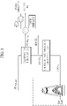
- FIG. 1 is an overall configuration diagram of utilization in production of carbon monoxide and production of molten iron according to an exemplary embodiment of the present invention.
- a process of producing molten iron in an integrated steel mill mainly relies on a blast furnace method, and mainly uses carbon monoxide emitted from coal as a reducing agent for iron ore, so a huge amount of carbon dioxide is emitted in the process of producing molten iron.
- carbon monoxide emitted from coal a reducing agent for iron ore
- a huge amount of carbon dioxide is emitted in the process of producing molten iron.
- about 2.18 tons of carbon dioxide is emitted.
- 80% of the carbon dioxide is emitted due to the use of coal in the process of producing molten iron.
- FIG. 1 a method of selectively separating and recovering carbon dioxide from an exhaust gas in a blast furnace, reforming the carbon dioxide into carbon monoxide, and re-blowing the carbon monoxide into the blast furnace is proposed, which is illustrated in FIG. 1 .
- the content of carbon dioxide in the exhaust gas component in the blast furnace is about 20 to 25%, and in the case of the blast furnace with an internal volume of 5000 Nm 3 or more, more than 16,000 Nm 3 of carbon dioxide is emitted per minute.
- the carbon monoxide is produced by the method presented in FIG. 1 .
- the temperature of the produced carbon monoxide is about 800°C, and the use of coke and PCI coal, which are used as reducing agents, may be saved by blowing the produced high-temperature carbon monoxide into a tuyere of the blast furnace.
- An exemplary embodiment of the present invention provides a method of producing molten iron, including: capturing carbon dioxide in an exhaust gas emitted from a blast furnace; reforming the carbon dioxide into carbon monoxide; and re-blowing the carbon monoxide into the blast furnace, in which, in the re-blowing of the carbon monoxide into the blast furnace, the amount of CO gas re-blown (Nm 3 /min) of [Equation 1] below may satisfy 500 or more and 1270 Nm 3 /min or less.
- the value of [Equation 1] may be specifically 500 to 970 Nm 3 /min, and more specifically 500 to 750 Nm 3 /min.
- Amount of CO gas re ⁇ blown Nm 3 / min Content of CO 2 gas in exhaust gas Nm 3 / ton ⁇ Molten iron output ton / day ⁇ Ratio of CO 2 gas blown into runner 50 % ⁇ CO gas conversion rate % ⁇ 1 day / 1440 min
- a CO gas circulation rate of [Equation 2] below may be 15 to 40%.
- the value of [Equation 2] may be specifically 16 to 32%, more specifically 24 to 32%, and even more specifically 24 to 30%.
- the value of the CO gas circulation value of [Equation 2] is less than 15%, there may be a slight problem in the CO 2 saving effect compared with the technology investment, and when the value of the CO gas circulation rate exceeds 40%, there may be a problem in that the amount of carbon monoxide is increased, and thus, the total input gas blown into the blast furnace is reduced, and an oxygen load should be increased in order to preserve the heat energy as much as the reduced total input gas.
- CO gas circulation rate % Amount of CO gas re - blown Nm 3 / min / Content of CO gas in exhaust gas Nm 3 / ton ⁇ Molten iron output ton / day ⁇ 1440 min / 1 day ⁇ 100 %
- the CO gas conversion rate of the above [Equation 1] or [Equation 2] may be 35% or more to less than 85%.
- the temperature of carbon monoxide may be 800°C or higher, specifically 800 to 1500°C, more specifically 900 to 1200°C, and even more specifically 1000 to 1100°C.
- the amount (kr/ton-pig) of pulverized coal blown according to the CO conversion rate of [Equation 3] below may satisfy 100 to 170 kg/ton-pig.
- the value of Equation 2 may be specifically 100 (kg/ton-pig) or more, more specifically 170 to 100, and even more specifically, 170.3 (kg/ton-pig) to 100.295 (kg/ton-pig).
- the carbon dioxide may be selectively captured by at least one selected from the group consisting of pressure swing adsorption (PSA), a deep cooling method, an ammonia/amine absorption method, an adsorbent usage, a metal organic framework (MOF), and a membrane separation method.
- PSA pressure swing adsorption
- MOF metal organic framework
- the conversion rate for reforming the carbon dioxide into carbon monoxide may be 35% or more, specifically 35 to 85%. More specifically, the conversion rate may be 35 to 64%, more specifically 35 to 50%.
- the reformed carbon monoxide may be recycled where a heat source is needed, such as drying refractory etc., in the runner in addition to being re-blown into the blast furnace through the tuyere of the blast furnace.
- a heat source such as drying refractory etc.
- FIG. 2 is a schematic partial configuration diagram of the production of carbon monoxide in the runner according to an embodiment of the present invention.
- sinter ore, coke, and limestone are blown from the top of the blast furnace and slowly fall down.
- the coke is burned by the hot air flowing into the bottom of the blast furnace, and the carbon monoxide emitted in this process undergoes a reduction reaction with iron ore to produce molten iron.
- the temperature of the produced melt is 1,500°C or higher. Radiant heat is emitted to the melt runner by this temperature, and the temperature of the radiant heat at this time is about 900°C to 1200°C.
- An apparatus for reforming carbon dioxide formed of a material with excellent conductivity is installed on top of this melt, and carbon dioxide is blown.
- the carbon-containing by-product and iron-containing by-product are mixed in a certain ratio and then filled inside, and the carbon dioxide is reformed into the carbon monoxide by utilizing the radiant heat from the melt.
- the carbon-containing by-product may supply a carbon source for reforming carbon dioxide into carbon monoxide, and the iron-containing by-product may act as a reforming catalyst.
- the apparatus for reforming carbon dioxide may promote a Boudouard reaction between the carbon dioxide and the carbon-containing byproducts to reform the carbon dioxide into the carbon monoxide as shown in the following reaction formula.
- the inside of the apparatus may be filled with a mixture of the carbon-containing by-product and the iron-containing by-product, and a mixing ratio of the carbon-containing by-product and the iron-containing by-product may include 10 to 50 wt% of the iron-containing by-product based on 100 wt% of the carbon-containing by-product.
- the mixing ratio of the carbon-containing by-product and the iron-containing by-product in the mixture may be adjusted according to the content of iron in the iron-containing by-product.
- the iron-containing by-product may be specifically 0 to 50 wt%, more specifically 10 to 40 wt%, and even more specifically 20 to 40 wt%.
- the surface of the carbon-containing by-product that reacts with CO 2 gas will be excessively covered, so there may be a problem in that an interface of the carbon-containing byproducts is rather reduced.
- the specific surface area of the carbon-containing by-product may be 50 m 2 /g or more, specifically 50 to 300 m 2 /g, more specifically 100 to 290 m 2 /g, even more specifically 200 to 285 m 2 /g, and even much more specifically 250 to 280 m 2 /g.
- the reaction of the carbon-containing by-product with gas is significantly lowered, so there may be a problem in that the reaction rate or conversion rate is lowered, and when the specific surface area is too large, such as when the specific surface area is more than 300 m 2 /g, since the carbon-containing by-product reacts with more gas, the reaction time is shortened, so there may be a problem in that it is difficult to control.
- the carbon component of the carbon-containing by-product may be 60 wt% or more, specifically, 80 to 90 wt%, and more specifically 82 to 87 wt%.
- the carbon component of the carbon-containing by-product is less than 60 wt%, there may be a problem in that the amount of converted gas is reduced by reducing the amount of carbon compared with the amount of gas blown, and when the carbon component is more than 90 wt%, there may be a problem in that there is a deactivated carbon component because there are a large amount of carbon components compared with the amount of gas blown.
- the iron-containing component of the iron-containing by-product may be 50 wt% or more, specifically 50 to 100 wt%, and more specifically 50 to 60 wt%.
- the iron-containing component of the iron-containing by-product is less than 50 wt%, since the active energy of the reaction is increased due to the reduction in the iron-containing component serving as a catalyst, the reaction rate is slowed down, so there may be a problem in that the conversion rate is lowered.
- the apparatus for reforming carbon dioxide is an apparatus for reforming carbon dioxide in exhaust gas emitted from a blast furnace, in which the apparatus for reforming carbon dioxide may be installed in a melt runner during an iron making process.
- the apparatus for reforming carbon dioxide may be installed in the melt runner during the iron making process to use the radiant heat of the melt (see FIG. 5 ).
- At least one apparatus for reforming carbon dioxide may be installed over the entire area of the melt runner.
- the apparatus for reforming carbon dioxide may be detachable depending on the operating conditions in the runner.
- a carbon dioxide blowing inlet may also be 1 or more.
- reaction tubes When the apparatus for reforming carbon dioxide is two or more, reaction tubes may be installed, fixed, and connected in a form of a bundle or a mesh.
- the melt runner may have a cover on the melt, and the apparatus for reforming carbon dioxide may be present between the melt and the cover.
- the temperature of the air between the melt and the cover may be 900°C or higher, specifically 900 to 1500°C, and more specifically 900 to 1200°C. This high-temperature heat is transferred to the apparatus for reforming carbon dioxide, where the carbon dioxide reacts with the carbon-containing by-product to be reformed into the carbon monoxide.
- the position of the apparatus for reforming carbon dioxide may be adjusted in consideration of the amount of melt in the runner. Specifically, the position of the apparatus for reforming carbon dioxide may be determined according to the temperature and amount of melt flowing in the runner.
- the apparatus for reforming carbon dioxide may be installed 100 to 500 mm from the top of the surface of the melt, and specifically 200 to 400 mm above.
- the apparatus for reforming carbon dioxide is installed too close from the top of the surface of the melt, there may be a problem in that the installed reaction tube is deformed, and when the apparatus for reforming carbon dioxide is installed too far from the top of the surface of the melt, there may be a problem in that, since the radiant heat is not sufficiently transmitted, the temperature inside the reaction tube does not become high enough to react.
- the material of the apparatus for reforming carbon dioxide is sufficient as long as the radiant heat from the melt in the melt runner is transmitted well, and may be at least one selected from the group consisting of tungsten, molybdenum, silicon carbide, and aluminum nitride, and specifically tungsten.
- the heat balance and carbon dioxide saving effect were calculated using a thermal mass balance equation.
- Table 1 shows the balance and carbon dioxide saving effect in the blast furnace according to the re-blowing of the carbon monoxide into the tuyere of the blast furnace for each carbon monoxide gas conversion rate produced according to the embodiment of the present invention in molten iron.
- CO conversion rate (%)
- Base* 85 65 50 35 CO circulation rate (%) - 32.5 24.9 19.2 13.4
- Total input gas (Nm 3 /t-p) 830.91 812.23 825.97 831.53 834.01 Difference absolute value in total input gas compared with base (Nm
- the circulation rate of the carbon monoxide produced from the runner to the tuyere of the blast furnace was calculated as 32.5% when the carbon monoxide conversion rate is 85%, 24.9% when the carbon monoxide conversion rate is 65%, 19.2% when the carbon monoxide conversion rate is 50%, and 13.4% when the carbon monoxide conversion rate is 35%.
- the amount of CO gas produced by reacting the carbon-containing by-product filled in the reactor installed in the runner with the CO 2 gas blown into the reactor is expressed as the conversion rate, and in order to blow the amount of CO gas produced for each conversion rate into the tuyere of the blast furnace, the amount of CO gas replaceable with respect to the total input gas blown into the tuyere of the blast furnace in consideration of the heat balance in the blast furnace is the circulation rate.
- the CO gas having the conversion rate of 50% showed the closest value to the total input gas blown into the blast furnace, but the bosh gas volume, which is an index for determining the heat balance at the bottom of the blast furnace, was lower than that of blowing the CO gas having the conversion rate of 30%. Accordingly, it can be seen that it is appropriate to re-blow the carbon dioxide having a conversion rate of 35% into the blast furnace in consideration of the amount of carbon dioxide gas emitted to the outside of the blast furnace while maintaining the heat balance inside the blast furnace.
- the CO gas conversion rate was changed as shown in Table 2 below, and the exhaust gas emission and the molten iron output were kept constant.
- the amount of CO gas re-blown was calculated according to Equation 1 below.
- Amount of CO gas re ⁇ blown Nm 3 / min Content of CO 2 gas in exhaust gas Nm 3 / ton ⁇ Molten iron output ton / day ⁇ Ratio of CO 2 gas blown into runner 50 % ⁇ CO gas conversion rate % ⁇ 1 day / 1440 min (Table 2) Comparati ve Example1 Comparat ive Example 2 Exemplar y embodim ent 1 Exemplar y embodim ent 2 Exemplar y embodim ent 3 Compar ative Exampl e 3 CO conversion rate (%) 90 85 65 50 35 25 Exhaust gas emission (Nm 3 /ton) 1410.89 1410.89 1410.89 1410.89 1410.89 1410.89 1410.89 1410.89 1410.89 1410.89 1410.89 1410.89 Content of CO in exhaust gas (%) 29.61 29.40 28.54 27.87 27.16 26.67 Ratio of CO 2 in exhaust gas (%) 28.45 28.25 27.42 26
- the iron-containing by-product was mixed with the carbon-containing by-product and filled in the reaction tube to increase the utilization of these by-products and further improve the carbon monoxide conversion rate. Thereafter, the carbon monoxide conversion rate was measured using the radiant heat in the runner.
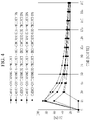
- the mixing ratio of the iron-containing by-product is 10 wt%, 20 wt%, 30 wt%, 40 wt%, and 60 wt% based on 100 wt% of the carbon-containing by-product, and Table 4 and FIG 4 showed the results of comparing the carbon monoxide conversion rate with the case of not mixing the iron-containing by-product.
Landscapes
- Engineering & Computer Science (AREA)
- Chemical & Material Sciences (AREA)
- Manufacturing & Machinery (AREA)
- Materials Engineering (AREA)
- Metallurgy (AREA)
- Organic Chemistry (AREA)
- Waste-Gas Treatment And Other Accessory Devices For Furnaces (AREA)
- Carbon And Carbon Compounds (AREA)
- Blast Furnaces (AREA)
- Manufacture Of Iron (AREA)
Abstract
Description
- The present disclosure relates to a method of producing carbon monoxide. More specifically, the present disclosure relates to a method of converting carbon dioxide into carbon monoxide to save carbon dioxide emission and utilizing the carbon monoxide.
- A reduction process in a steel industry is a process in which carbon in coke and iron ore undergo a chemical reaction due to a high temperature in a blast furnace called a smelting furnace to obtain liquid iron. A problem with a current steelmaking process is that a large amount of carbon dioxide (CO2) is inevitably emitted by using a carbon-based reducing agent such as coal for the reduction process. However, as pressures on carbon dioxide emission regulations are intensified around the world, the steel industry is increasingly interested in environmentally-friendly in terms of environment, energy, and cost competitiveness. In particular, after the Kyoto Protocol, efforts to save CO2 emission and save energy have been accelerating. Since a carbon tax is being applied to the steel industry as well, interest in a method of lowering a reducing agent ratio used in a blast furnace and a method of saving carbon dioxide emission is increasing recently.
- In order to save the amount of carbon dioxide emitted in a process of producing molten iron, it is important to efficiently use an exhaust gas emitted during the production of the molten iron. Main components of the exhaust gas emitted during the production of the molten iron include CO, H2, CO2, H2O, N2, and the like, and CO and H2 in the exhaust gas can be used as a reducing agent or a heat source that generates heat.
- Therefore, as efforts to save the reducing agent ratio and carbon dioxide used in the blast furnace, a technology of selecting only carbon monoxide (CO) in an exhaust gas in a blast furnace and re-blowing the selected carbon monoxide (CO) into the blast furnace, a technology of using, as a medium, hydrogen in place of carbon (coal) to lower the reducing agent ratio through hydrogen reduction and fundamentally block carbon dioxide emission, and the like are being researched. However, the technology of selectively separating and recovering carbon monoxide and re-blowing the carbon monoxide into a blast furnace has a problem in that a recovery rate of separation and recovery of CO and N2 in an exhaust gas is low, and the hydrogen reduction technology using hydrogen as a medium has a problem in that economical efficiency is low and changes in operation cannot be predicted when a reducing agent is used. In addition, in order to re-blow the separated CO gas and produced hydrogen gas into the blast furnace, there is a problem in that temperature needs to be raised to 1200°C or higher, which is a blowing temperature of the blast furnace, in consideration of a heat balance inside the blast furnace. Accordingly, technology development is still required.
- The present invention has been made in an effort to provide a method of selectively separating and capturing carbon dioxide in an exhaust gas in a blast furnace, recycling by-products produced in a steel mill to reduce the carbon dioxide to the carbon monoxide, and re-blowing the produced carbon monoxide into the blast furnace.
- An exemplary embodiment of the present invention provides a method of producing molten iron, including: capturing carbon dioxide in an exhaust gas emitted from a blast furnace; reforming the carbon dioxide into carbon monoxide; and re-blowing the carbon monoxide into the blast furnace, in which, in the re-blowing of the carbon monoxide into the blast furnace, CO gas re-blowing amount (Nm3/min) of [Equation 1] below may satisfy 500 or more and 1270 or less.

- A CO gas circulation rate of [Equation 2] below may be 15 to 40%.

- The CO gas conversion rate of the above [Equation 1] or [Equation 2] may be 35% or more to less than 85%.
- In the re-blowing of the carbon monoxide into the blast furnace, a temperature of the carbon monoxide may be 800°C or higher.
- In the re-blowing of the carbon monoxide into the blast furnace, the amount (kr/ton-pig) of pulverized coal blown according to the CO conversion rate of [Equation 3] below may satisfy 100 to 170 kg/ton-pig.

- Another embodiment of the present invention provides an apparatus for reforming carbon dioxide, in which an inside of the apparatus may be filled with a mixture of a carbon-containing by-product and an iron-containing by-product, a mixing ratio of the carbon-containing by-product and the iron-containing by-product may include 10 to 50 wt% of the iron-containing by-product based on 100 wt% of the carbon-containing by-product, and the carbon dioxide may be reformed into carbon monoxide.
- A specific surface area of the carbon-containing by-product may be 50 m2/g or more.
- A carbon component of the carbon-containing by-product may be 80 wt% or more, and an iron-containing component of the iron-containing by-product may be 50 wt% or more.
- Yet another embodiment of the present invention provides an apparatus for reforming carbon dioxide in exhaust gas emitted from a blast furnace, in which the apparatus for reforming carbon dioxide may be installed in a melt runner during an iron making process.
- At least one apparatus for reforming carbon dioxide may be installed over the entire area of the melt runner.
- When the apparatus for reforming carbon dioxide is two or more, reaction tubes may be installed, fixed, and connected in a form of a bundle or a mesh.
- The melt runner may have a cover on the melt, and the apparatus for reforming carbon dioxide may be present between the melt and the cover.
- The temperature between the melt in the melt runner and the cover may be 900°C or higher.
- A position of the apparatus for reforming carbon dioxide may be adjusted in consideration of the amount of melt in the melt runner.
- According to an embodiment of the present invention, it is possible to reform carbon dioxide captured in a blast furnace into carbon monoxide in an apparatus for reforming carbon dioxide.
- In addition, according to an embodiment of the present invention, when the apparatus for reforming carbon dioxide is re-blown into a blast furnace by using radiant heat from a melt in a melt runner, it is possible to maintain an energy balance in the blast furnace.
- In addition, according to an embodiment of the present invention, since carbon dioxide in an exhaust gas of a blast furnace is captured and used, it is possible to save carbon dioxide emission.
- In addition, according to an embodiment of the present invention, it is possible to save a reducing agent ratio by re-blowing the produced carbon monoxide into a blast furnace
-
-
FIG. 1 is a diagram illustrating an overall configuration diagram of production and utilization of carbon monoxide according to an exemplary embodiment of the present invention. -
FIG. 2 is a schematic partial configuration diagram of positioning an apparatus for reforming carbon dioxide in a runner according to an exemplary embodiment of the present invention. -
FIG. 3 is a diagram illustrating a carbon monoxide conversion rate of carbon-containing by-product utilizing radiant heat according to an exemplary embodiment of the present invention. -
FIG. 4 is a diagram illustrating carbon monoxide conversion rates of carbon-containing by-product and iron-containing by-product utilizing radiant heat according to an exemplary embodiment of the present invention. -
FIG. 5 is a schematic diagram of a CO reforming reaction tube installed in the runner. - The terms first, second, third, and the like are used to describe, but are not limited to, various parts, components, areas, layers and/or sections. These terms are used only to distinguish a part, component, region, layer, or section from other parts, components, regions, layers, or sections. Accordingly, a first part, a component, an area, a layer, or a section described below may be referred to as a second part, a component, a region, a layer, or a section without departing from the scope of the present invention.
- Terminologies used herein are to mention only a specific exemplary embodiment, and are not to limit the present invention. Singular forms used herein include plural forms as long as phrases do not clearly indicate an opposite meaning. The meaning "including" used in the present specification concretely indicates specific properties, areas, integer numbers, steps, operations, elements, and/or components, and is not to exclude presence or addition of other specific properties, areas, integer numbers, steps, operations, elements, and/or components thereof.
- When a part is referred to as being "above" or "on" other parts, it may be directly above or on other parts, or other parts may be included in between. In contrast, when a part is referred to as being "directly above" another part, no other part is involved in between.
- In addition, unless otherwise specified, % means wt%, and 1 ppm is 0.0001 wt%.
- All terms including technical terms and scientific terms used herein have the same meaning as the meaning generally understood by those skilled in the art to which the present invention pertains unless defined otherwise. Commonly used terms defined in the dictionary are additionally interpreted as having a meaning consistent with the related technical literature and the presently disclosed content, and unless defined, are not interpreted in an ideal or very formal meaning.
- Hereinafter, an exemplary embodiment of the present invention will be described in detail so that a person of ordinary skill in the art to which the present invention pertains can easily implement the present invention. The present invention may be modified in various different ways, and is not limited to the exemplary embodiments described herein.
-
FIG. 1 is an overall configuration diagram of utilization in production of carbon monoxide and production of molten iron according to an exemplary embodiment of the present invention. Currently, a process of producing molten iron in an integrated steel mill mainly relies on a blast furnace method, and mainly uses carbon monoxide emitted from coal as a reducing agent for iron ore, so a huge amount of carbon dioxide is emitted in the process of producing molten iron. For example, in order to produce 1 ton of steel products, about 2.18 tons of carbon dioxide is emitted. 80% of the carbon dioxide is emitted due to the use of coal in the process of producing molten iron. Meanwhile, the price of coking coal suitable for the blast furnace process has risen sharply due to the recent surge in fuel prices in the steel industry, making the price competitiveness of the process of producing molten iron worse. In order to solve this problem, a method of selectively separating and recovering carbon dioxide from an exhaust gas in a blast furnace, reforming the carbon dioxide into carbon monoxide, and re-blowing the carbon monoxide into the blast furnace is proposed, which is illustrated inFIG. 1 . The content of carbon dioxide in the exhaust gas component in the blast furnace is about 20 to 25%, and in the case of the blast furnace with an internal volume of 5000 Nm3 or more, more than 16,000 Nm3 of carbon dioxide is emitted per minute. In order to selectively separate and recover only carbon dioxide and convert the carbon dioxide into the carbon monoxide, the carbon monoxide is produced by the method presented inFIG. 1 . In this case, the temperature of the produced carbon monoxide is about 800°C, and the use of coke and PCI coal, which are used as reducing agents, may be saved by blowing the produced high-temperature carbon monoxide into a tuyere of the blast furnace. - Hereinafter, the method of producing molten iron for reforming carbon dioxide into carbon monoxide and re-blowing the carbon monoxide will be described in more detail.
- An exemplary embodiment of the present invention provides a method of producing molten iron, including: capturing carbon dioxide in an exhaust gas emitted from a blast furnace; reforming the carbon dioxide into carbon monoxide; and re-blowing the carbon monoxide into the blast furnace, in which, in the re-blowing of the carbon monoxide into the blast furnace, the amount of CO gas re-blown (Nm3/min) of [Equation 1] below may satisfy 500 or more and 1270 Nm3/min or less. The value of [Equation 1] may be specifically 500 to 970 Nm3/min, and more specifically 500 to 750 Nm3/min. When the value of [Equation 1] is less than 500 Nm3/min, there may be a slight problem in the CO2 saving effect compared with the technology investment, and when the value of [Equation 1] exceeds 1270 Nm3/min, there may be a problem in that the amount of carbon monoxide is increased, and thus, a total input gas blown into the blast furnace is reduced, and an oxygen load should be increased in order to preserve heat energy as much as the reduced total input gas.

- In the method of producing molten iron, a CO gas circulation rate of [Equation 2] below may be 15 to 40%. The value of [Equation 2] may be specifically 16 to 32%, more specifically 24 to 32%, and even more specifically 24 to 30%. When the value of the CO gas circulation value of [Equation 2] is less than 15%, there may be a slight problem in the CO2 saving effect compared with the technology investment, and when the value of the CO gas circulation rate exceeds 40%, there may be a problem in that the amount of carbon monoxide is increased, and thus, the total input gas blown into the blast furnace is reduced, and an oxygen load should be increased in order to preserve the heat energy as much as the reduced total input gas.

- The CO gas conversion rate of the above [Equation 1] or [Equation 2] may be 35% or more to less than 85%.
- In the re-blowing of the carbon monoxide into the blast furnace, the temperature of carbon monoxide may be 800°C or higher, specifically 800 to 1500°C, more specifically 900 to 1200°C, and even more specifically 1000 to 1100°C.
- In the re-blowing of the carbon monoxide into the blast furnace, the amount (kr/ton-pig) of pulverized coal blown according to the CO conversion rate of [Equation 3] below may satisfy 100 to 170 kg/ton-pig. The value of
Equation 2 may be specifically 100 (kg/ton-pig) or more, more specifically 170 to 100, and even more specifically, 170.3 (kg/ton-pig) to 100.295 (kg/ton-pig). When the amount of pulverized coal blown of [Equation 3] is less than 100 kg/ton-pig, there may be a problem in that a heat value in the blast furnace is insufficient, and when the amount of pulverized coal blown exceeds 170 kg/ton-pig, there may be a problem in that the purpose of saving the reducing agent ratio by increasing the pulverized coal ratio or reducing the amount of coke used may not be achieved due to the increased pressure for ventilation in the blast furnace.
- In the capturing of the carbon dioxide in the exhaust gas emitted from the blast furnace, the carbon dioxide may be selectively captured by at least one selected from the group consisting of pressure swing adsorption (PSA), a deep cooling method, an ammonia/amine absorption method, an adsorbent usage, a metal organic framework (MOF), and a membrane separation method.
- The conversion rate for reforming the carbon dioxide into carbon monoxide may be 35% or more, specifically 35 to 85%. More specifically, the conversion rate may be 35 to 64%, more specifically 35 to 50%.
- The reformed carbon monoxide may be recycled where a heat source is needed, such as drying refractory etc., in the runner in addition to being re-blown into the blast furnace through the tuyere of the blast furnace.
-
FIG. 2 is a schematic partial configuration diagram of the production of carbon monoxide in the runner according to an embodiment of the present invention. In general, sinter ore, coke, and limestone are blown from the top of the blast furnace and slowly fall down. In this case, the coke is burned by the hot air flowing into the bottom of the blast furnace, and the carbon monoxide emitted in this process undergoes a reduction reaction with iron ore to produce molten iron. In this case, the temperature of the produced melt is 1,500°C or higher. Radiant heat is emitted to the melt runner by this temperature, and the temperature of the radiant heat at this time is about 900°C to 1200°C. An apparatus for reforming carbon dioxide formed of a material with excellent conductivity is installed on top of this melt, and carbon dioxide is blown. The carbon-containing by-product and iron-containing by-product are mixed in a certain ratio and then filled inside, and the carbon dioxide is reformed into the carbon monoxide by utilizing the radiant heat from the melt. The carbon-containing by-product may supply a carbon source for reforming carbon dioxide into carbon monoxide, and the iron-containing by-product may act as a reforming catalyst. - Hereinafter, each configuration of the apparatus for reforming carbon dioxide will be described in more detail.
- The apparatus for reforming carbon dioxide according to an exemplary embodiment of the present invention may promote a Boudouard reaction between the carbon dioxide and the carbon-containing byproducts to reform the carbon dioxide into the carbon monoxide as shown in the following reaction formula.
CO2+ C → 2CO
- In the apparatus for reforming carbon dioxide according to embodiment of the present invention, the inside of the apparatus may be filled with a mixture of the carbon-containing by-product and the iron-containing by-product, and a mixing ratio of the carbon-containing by-product and the iron-containing by-product may include 10 to 50 wt% of the iron-containing by-product based on 100 wt% of the carbon-containing by-product.
- The mixing ratio of the carbon-containing by-product and the iron-containing by-product in the mixture may be adjusted according to the content of iron in the iron-containing by-product. Based on 100 wt% of the carbon-containing by-product, the iron-containing by-product may be specifically 0 to 50 wt%, more specifically 10 to 40 wt%, and even more specifically 20 to 40 wt%. When the iron-containing by-product is mixed in excess of 50 wt% based on 100 wt% of the carbon-containing by-product, the surface of the carbon-containing by-product that reacts with CO2 gas will be excessively covered, so there may be a problem in that an interface of the carbon-containing byproducts is rather reduced.
- The specific surface area of the carbon-containing by-product may be 50 m2/g or more, specifically 50 to 300 m2/g, more specifically 100 to 290 m2/g, even more specifically 200 to 285 m2/g, and even much more specifically 250 to 280 m2/g. When the specific surface area is less than 50 m2/g, the reaction of the carbon-containing by-product with gas is significantly lowered, so there may be a problem in that the reaction rate or conversion rate is lowered, and when the specific surface area is too large, such as when the specific surface area is more than 300 m2/g, since the carbon-containing by-product reacts with more gas, the reaction time is shortened, so there may be a problem in that it is difficult to control.
- The carbon component of the carbon-containing by-product may be 60 wt% or more, specifically, 80 to 90 wt%, and more specifically 82 to 87 wt%. When the carbon component of the carbon-containing by-product is less than 60 wt%, there may be a problem in that the amount of converted gas is reduced by reducing the amount of carbon compared with the amount of gas blown, and when the carbon component is more than 90 wt%, there may be a problem in that there is a deactivated carbon component because there are a large amount of carbon components compared with the amount of gas blown.
- The iron-containing component of the iron-containing by-product may be 50 wt% or more, specifically 50 to 100 wt%, and more specifically 50 to 60 wt%. When the iron-containing component of the iron-containing by-product is less than 50 wt%, since the active energy of the reaction is increased due to the reduction in the iron-containing component serving as a catalyst, the reaction rate is slowed down, so there may be a problem in that the conversion rate is lowered.
- In addition, the apparatus for reforming carbon dioxide according to the exemplary embodiment of the present invention is an apparatus for reforming carbon dioxide in exhaust gas emitted from a blast furnace, in which the apparatus for reforming carbon dioxide may be installed in a melt runner during an iron making process. The apparatus for reforming carbon dioxide may be installed in the melt runner during the iron making process to use the radiant heat of the melt (see
FIG. 5 ). - At least one apparatus for reforming carbon dioxide may be installed over the entire area of the melt runner. In addition, the apparatus for reforming carbon dioxide may be detachable depending on the operating conditions in the runner. In addition, as the apparatus for reforming carbon dioxide is 1 or more, a carbon dioxide blowing inlet may also be 1 or more.
- When the apparatus for reforming carbon dioxide is two or more, reaction tubes may be installed, fixed, and connected in a form of a bundle or a mesh.
- The melt runner may have a cover on the melt, and the apparatus for reforming carbon dioxide may be present between the melt and the cover.
- The temperature of the air between the melt and the cover may be 900°C or higher, specifically 900 to 1500°C, and more specifically 900 to 1200°C. This high-temperature heat is transferred to the apparatus for reforming carbon dioxide, where the carbon dioxide reacts with the carbon-containing by-product to be reformed into the carbon monoxide.
- The position of the apparatus for reforming carbon dioxide may be adjusted in consideration of the amount of melt in the runner. Specifically, the position of the apparatus for reforming carbon dioxide may be determined according to the temperature and amount of melt flowing in the runner.
- Specifically, when the melt flows in the melt runner, the apparatus for reforming carbon dioxide may be installed 100 to 500 mm from the top of the surface of the melt, and specifically 200 to 400 mm above. When the apparatus for reforming carbon dioxide is installed too close from the top of the surface of the melt, there may be a problem in that the installed reaction tube is deformed, and when the apparatus for reforming carbon dioxide is installed too far from the top of the surface of the melt, there may be a problem in that, since the radiant heat is not sufficiently transmitted, the temperature inside the reaction tube does not become high enough to react.
- The material of the apparatus for reforming carbon dioxide is sufficient as long as the radiant heat from the melt in the melt runner is transmitted well, and may be at least one selected from the group consisting of tungsten, molybdenum, silicon carbide, and aluminum nitride, and specifically tungsten.
- Hereinafter, the present invention will be described in more detail through exemplary embodiments. However, these exemplary embodiments are merely intended to illustrate the present invention, and the present invention is not limited thereto.
- In the present invention, in order to investigate the heat balance and carbon dioxide saving effect by reforming the carbon dioxide gas in the exhaust gas in the blast furnace into the carbon monoxide and re-blowing the carbon monoxide into the tuyere of the blast furnace, the heat balance and carbon dioxide saving effect were calculated using a thermal mass balance equation.
- Table 1 shows the balance and carbon dioxide saving effect in the blast furnace according to the re-blowing of the carbon monoxide into the tuyere of the blast furnace for each carbon monoxide gas conversion rate produced according to the embodiment of the present invention in molten iron.
(Table 1) CO conversion rate (%) Base* 85 65 50 35 CO circulation rate (%) - 32.5 24.9 19.2 13.4 Ratio of pulverized coal blown of [Equation 3] (kg/t-p*) 170.3 119.7 140.7 152.8 161.7 Difference value compared with base (kg/t-p) - 50.8 29.7 17.6 8.6 Carbon reduction amount compared with base (kg/t-p) - 42.6 24.9 14.8 -7.2 CO2 saving compared with base (kg/t-p) - 156.3 91.4 54.1 26.5 Total input gas (Nm3/t-p) 830.91 812.23 825.97 831.53 834.01 Difference absolute value in total input gas compared with base (Nm3/t-p) - 18.68 4.94 0.62 3.1 Bosh gas volume 740.57 575.86 614.34 643.68 672.75 *Base refers to the existing blast furnace into which carbon monoxide is not blown.
*t-p refers to ton-pig.
- For each carbon monoxide conversion rate, the circulation rate of the carbon monoxide produced from the runner to the tuyere of the blast furnace was calculated as 32.5% when the carbon monoxide conversion rate is 85%, 24.9% when the carbon monoxide conversion rate is 65%, 19.2% when the carbon monoxide conversion rate is 50%, and 13.4% when the carbon monoxide conversion rate is 35%. The amount of CO gas produced by reacting the carbon-containing by-product filled in the reactor installed in the runner with the CO2 gas blown into the reactor is expressed as the conversion rate, and in order to blow the amount of CO gas produced for each conversion rate into the tuyere of the blast furnace, the amount of CO gas replaceable with respect to the total input gas blown into the tuyere of the blast furnace in consideration of the heat balance in the blast furnace is the circulation rate.
- The effect of saving the reducing agent ratio according to the carbon monoxide conversion rate to about 50 kg/t-p of pulverized coal when carbon monoxide having a conversion rate of 85% is blown was shown. In this case, the carbon saving was shown as about 43kg/t-p, and the CO2 saving effect was shown as about 156kg/t-p. However, it can be seen that re-blowing the carbon monoxide having the conversion rate of 85% increases the amount of carbon monoxide as the circulation rate is increased, and thus, the total input gas blown into the blast furnace is reduced by about 20 Nm3/t-p, so there is a disadvantage in that the oxygen load should be increased in order to preserve the heat energy as much as the reduced total input gas. In addition, the CO gas having the conversion rate of 50% showed the closest value to the total input gas blown into the blast furnace, but the bosh gas volume, which is an index for determining the heat balance at the bottom of the blast furnace, was lower than that of blowing the CO gas having the conversion rate of 30%. Accordingly, it can be seen that it is appropriate to re-blow the carbon dioxide having a conversion rate of 35% into the blast furnace in consideration of the amount of carbon dioxide gas emitted to the outside of the blast furnace while maintaining the heat balance inside the blast furnace.
- An experiment was conducted to find out the amount of CO gas re-blown into the blast furnace according to the carbon dioxide conversion rate.
- The CO gas conversion rate was changed as shown in Table 2 below, and the exhaust gas emission and the molten iron output were kept constant.
- The amount of CO gas re-blown was calculated according to Equation 1 below.

(Table 2) Comparati ve Example1 Comparat ive Example 2 Exemplar y embodim ent 1 Exemplar y embodim ent 2 Exemplar y embodim ent 3 Compar ative Exampl e 3 CO conversion rate (%) 90 85 65 50 35 25 Exhaust gas emission (Nm3/ton) 1410.89 1410.89 1410.89 1410.89 1410.89 1410.89 Content of CO in exhaust gas (%) 29.61 29.40 28.54 27.87 27.16 26.67 Ratio of CO2 in exhaust gas (%) 28.45 28.25 27.42 26.78 26.10 25.62 Content of CO2 in exhaust gas (Nm3/ton) 401.4 398.6 386.9 377.8 368.2 361.5 Molten iron output (ton/day) 14000 14000 14000 14000 14000 14000 Gas CO output in runner (Nm3/min) 1488.29 1488.29 1488.29 1488.29 1488.29 1488.29 Amount of CO gas re-blown according to Equation 1 (Nm3/min) 1756.11 1646.90 1222.39 918.35 626.52 439.29 Total input gas (Nm3/ton) 566.17 575.86 614.62 643.68 672.25 692.13 Circulation rate (%) 43.25 40.85 31.23 24.03 16.82 12.01 - As can be seen from the above results, when the amount of CO gas re-blown exceeds 1270 Nm3/min, the amount of carbon dioxide re-blown is increased as much, and accordingly, the total input gas blown into the blast furnace is reduced, which may be confirmed from the table. In the end, there will be a disadvantage in that the oxygen load needs to increase in order to preserve the heat energy as much as the reduced total input gas. In addition, when the amount of CO gas re-blown is less than 500 Nm3/min, the carbon saving or CO2 saving effect is lowered as much, and the ultimate object of the present invention to achieve energy saving and environmental protection effects is not accomplished.
- In order to realize the production of carbon monoxide in the apparatus for reforming carbon dioxide using the radiant heat in the runner, by blowing the carbon dioxide into the reaction tube filled with the carbon-containing byproducts with different specific surface areas as shown in Table 3, respectively, the conversion rate according to temperature was measured. It can be seen that the carbon monoxide conversion rate is increased as the reaction temperature is increased by the radiant heat in the runner, and at the same reaction temperature, it was observed that a conversion rate of a carbon-containing by-product having an excellent specific surface area was 20% better (see
FIG. 3 ). However, it can be seen that, since there is a disadvantage in that re-blowing the carbon monoxide having the conversion rate of 85% reduces the total input gas blown into the blast furnace, and thus, the oxygen load should be increased to preserve the heat energy as much as the reduced total input gas, it is not preferable that the specific surface area is too large.(Table 3) Specific surface area (mm2/g) Conversion rate (%) Comparative Example 1 47.73 33 Exemplary embodiment 1 50 37 Exemplary embodiment 2279.51 70 Exemplary embodiment 3 299.77 85 Comparative Example 2 334.29 88.3 * Conversion rate measurement: Volume of CO produced compared with a volume of CO2 blown into a reactor - Since there are by-products with a low specific surface area in the carbon-containing by-product, the iron-containing by-product was mixed with the carbon-containing by-product and filled in the reaction tube to increase the utilization of these by-products and further improve the carbon monoxide conversion rate. Thereafter, the carbon monoxide conversion rate was measured using the radiant heat in the runner. The mixing ratio of the iron-containing by-product is 10 wt%, 20 wt%, 30 wt%, 40 wt%, and 60 wt% based on 100 wt% of the carbon-containing by-product, and Table 4 and
FIG 4 showed the results of comparing the carbon monoxide conversion rate with the case of not mixing the iron-containing by-product. As a result, it could be confirmed that the conversion rate was superior to the case in which the iron-containing by-product is added compared with the case in which the iron-containing by-product is not added. In addition, it could be confirmed that the conversion rate is decreased when the ratio of the iron-containing by-product is rather increased too much.(Table 4) Content of iron-containing by-product (%) Conversion rate (%) Comparative Example 1 0 33.2 exemplary embodiment 1 10 34.9 exemplary embodiment 220 52.2 exemplary embodiment 3 30 63.5 exemplary embodiment 4 40 83.8 Comparative Example 2 60 69.8 - The present invention is not limited to the exemplary embodiments, but may be manufactured in a variety of different forms, and those of ordinary skill in the art to which the present invention pertains will understand that the present invention may be implemented in other specific forms without changing the technical spirit or essential features of the present invention. Therefore, it should be understood that the above-described exemplary embodiments are exemplary in all aspects but are not limited thereto.
Claims (14)
- A method of producing molten iron, comprising:capturing carbon dioxide in an exhaust gas emitted from a blast furnace;reforming the carbon dioxide into carbon monoxide; andre-blowing the carbon monoxide into the blast furnace, wherein, in the re-blowing of the carbon monoxide into the blast furnace,an amount of CO gas re-blown (Nm3/min) of [Equation 1] below satisfies 500 or more and 1270 or less.

- The method of claim 1, wherein:
a CO gas circulation rate of [Equation 2] below is 15 to 40%.
- The method of claim 1, wherein:
the CO gas conversion rate of the above [Equation 1] is 35% or more to less than 85%. - The method of claim 1, wherein:in the re-blowing of the carbon monoxide into the blast furnace,a temperature of the carbon monoxide is 800°C or higher.
- The method of claim 1, wherein:
in the re-blowing of the carbon monoxide into the blast furnace, an amount of pulverized coal blown according to the CO conversion rate of [Equation 3] below satisfies 100 to 170 kg/ton-pig.
- An apparatus for reforming carbon dioxide, whereinan inside of the apparatus is filled with a mixture of a carbon-containing by-product and an iron-containing by-product,a mixing ratio of the carbon-containing by-product and the iron-containing by-product includes 10 to 50 wt% of the iron-containing by-product based on 100 wt% of the carbon-containing by-product, andthe carbon dioxide is reformed into carbon monoxide.
- The apparatus of claim 6, wherein:
a specific surface area of the carbon-containing by-product is 50 m2/g or more. - The apparatus of claim 6, wherein:a carbon component of the carbon-containing by-product is 80 wt% or more, andan iron-containing component of the iron-containing by-product is 50 wt% or more.
- An apparatus for reforming carbon dioxide in exhaust gas emitted from a blast furnace, wherein
the apparatus for reforming carbon dioxide is installed in a melt runner during an iron making process. - The apparatus of claim 9, wherein:
at least one apparatus for reforming carbon dioxide is installed over the entire area of the melt runner. - The apparatus of claim 9, wherein:when the apparatus for reforming carbon dioxide is two or more,reaction tubes are installed, fixed, and connected in a form of a bundle or a mesh.
- The apparatus of claim 9, wherein:the melt runner has a cover on the melt, andthe apparatus for reforming carbon dioxide is present between the melt and the cover.
- The apparatus of claim 12, wherein:
the temperature between the melt in the melt runner and the cover is 900°C or higher. - The apparatus of claim 9, wherein:
a position of the apparatus for reforming carbon dioxide is adjusted in consideration of an amount of melt in the melt runner.
Applications Claiming Priority (2)
| Application Number | Priority Date | Filing Date | Title |
|---|---|---|---|
| KR1020190149711A KR102322712B1 (en) | 2019-11-20 | 2019-11-20 | Method of manufacturing carbonmonoxide and its use |
| PCT/KR2020/016101 WO2021101193A1 (en) | 2019-11-20 | 2020-11-16 | Method for producing carbon monoxide and use thereof |
Publications (2)
| Publication Number | Publication Date |
|---|---|
| EP4063524A1 true EP4063524A1 (en) | 2022-09-28 |
| EP4063524A4 EP4063524A4 (en) | 2023-05-10 |
Family
ID=75980865
Family Applications (1)
| Application Number | Title | Priority Date | Filing Date |
|---|---|---|---|
| EP20889482.4A Pending EP4063524A4 (en) | 2019-11-20 | 2020-11-16 | Method for producing carbon monoxide and use thereof |
Country Status (5)
| Country | Link |
|---|---|
| EP (1) | EP4063524A4 (en) |
| JP (1) | JP7307858B2 (en) |
| KR (1) | KR102322712B1 (en) |
| CN (1) | CN114729407A (en) |
| WO (1) | WO2021101193A1 (en) |
Families Citing this family (3)
| Publication number | Priority date | Publication date | Assignee | Title |
|---|---|---|---|---|
| CN114317853B (en) * | 2022-01-17 | 2022-12-30 | 新疆八一钢铁股份有限公司 | Based on 2500m 3 Heating method for high-temperature gas by carbon-carbon circulation blowing of blast furnace gas |
| CN114634831A (en) * | 2022-03-25 | 2022-06-17 | 新疆八一钢铁股份有限公司 | Process method for reforming circulating metallurgical gas by blast furnace injection plasma moment |
| KR102907706B1 (en) * | 2024-03-21 | 2026-01-06 | 한국공학대학교산학협력단 | A method of producing carbon monoxide from carbon dioxide using a melting furnace |
Family Cites Families (12)
| Publication number | Priority date | Publication date | Assignee | Title |
|---|---|---|---|---|
| CN102027140A (en) * | 2008-05-16 | 2011-04-20 | 杰富意钢铁株式会社 | Modification method and cooling method of exhaust gas produced by metallurgical furnace and their device |
| KR101235268B1 (en) * | 2010-12-01 | 2013-02-20 | 주식회사 포스코 | Carbon dioxide reformer from finex off gas and method for reforming thereof |
| DE102011077819A1 (en) * | 2011-06-20 | 2012-12-20 | Siemens Aktiengesellschaft | Carbon dioxide reduction in steelworks |
| KR101285786B1 (en) * | 2011-12-22 | 2013-07-22 | 주식회사 포스코 | Carbon dioixde sequester using molten slag |
| KR101377505B1 (en) * | 2012-05-31 | 2014-03-25 | 현대제철 주식회사 | Electric generator for pig casting machine |
| UA115346C2 (en) * | 2012-12-18 | 2017-10-25 | Басф Се | Process for utilizing blast furnace gases, associated gases and/or biogases |
| ES2694753T3 (en) * | 2013-12-20 | 2018-12-27 | L'air Liquide, Societe Anonyme Pour L'etude Et L'exploitation Des Procedes Georges Claude | Method of operation of a top gas blast furnace installation |
| US9840756B1 (en) * | 2014-10-17 | 2017-12-12 | U.S. Department Of Energy | System and method for regeneration and recirculation of a reducing agent using highly exothermic reactions induced by mixed industrial slags |
| JP6222132B2 (en) * | 2015-02-24 | 2017-11-01 | Jfeスチール株式会社 | Hydrocarbon carbon dioxide reforming method |
| JP6350430B2 (en) * | 2015-07-27 | 2018-07-04 | Jfeスチール株式会社 | Hydrocarbon carbon dioxide reforming method, hydrocarbon carbon dioxide reforming apparatus, and method for producing carbon monoxide and hydrogen |
| KR101758521B1 (en) * | 2015-12-23 | 2017-07-17 | 주식회사 포스코 | Apparatus and Method of Recycling and Decomposition of Carbon Dioxide via Accumulated Energy of Hot Stove |
| CN105671228B (en) * | 2016-02-29 | 2018-02-27 | 神雾科技集团股份有限公司 | Oxygen blast furnace and gas-based shaft kiln Joint Production system and combine production method |
-
2019
- 2019-11-20 KR KR1020190149711A patent/KR102322712B1/en active Active
-
2020
- 2020-11-16 JP JP2022529655A patent/JP7307858B2/en active Active
- 2020-11-16 CN CN202080080444.4A patent/CN114729407A/en active Pending
- 2020-11-16 WO PCT/KR2020/016101 patent/WO2021101193A1/en not_active Ceased
- 2020-11-16 EP EP20889482.4A patent/EP4063524A4/en active Pending
Also Published As
| Publication number | Publication date |
|---|---|
| KR20210061773A (en) | 2021-05-28 |
| EP4063524A4 (en) | 2023-05-10 |
| KR102322712B1 (en) | 2021-11-04 |
| WO2021101193A1 (en) | 2021-05-27 |
| JP7307858B2 (en) | 2023-07-12 |
| JP2023503296A (en) | 2023-01-27 |
| CN114729407A (en) | 2022-07-08 |
Similar Documents
| Publication | Publication Date | Title |
|---|---|---|
| CN102010924B (en) | Method for producing directly reduced iron from coal | |
| EP4357466B1 (en) | Method for producing reduced iron | |
| KR102322712B1 (en) | Method of manufacturing carbonmonoxide and its use | |
| CN108265145A (en) | A kind of utilization method and system of carbon dioxide enriched blast furnace gas | |
| US8709131B2 (en) | Method and system for the production of direct reduced iron using a synthesis gas with a high carbon monoxide content | |
| CN115261541A (en) | Molten iron manufacturing apparatus and molten iron manufacturing method | |
| JP2022505386A (en) | Carbon dioxide emission reduction type molten iron manufacturing equipment and its manufacturing method | |
| WO2013064870A1 (en) | Process for producing direct reduced iron (dri) with less co2 emissions to the atmosphere | |
| EP4596721A1 (en) | Reduced iron manufacturing method | |
| WO2023074061A1 (en) | Method for operating methane gas generation device, method for operating blast furnace, method for producing methane gas, method for producing hot metal, and methane gas generation device | |
| JP7605375B2 (en) | Method for producing reduced iron | |
| JP7700980B1 (en) | Method for operating reduction furnace and method for producing reduced iron | |
| EP4596722A1 (en) | Reduced iron production method | |
| EP4621076A1 (en) | Reduced iron production method | |
| WO2026048419A1 (en) | Method for producing reduced iron and system for producing reduced iron | |
| WO2013122583A1 (en) | Method and system for the production of direct reduced iron using a synthesis gas with a high carbon monoxide content | |
| AU2017372827B2 (en) | Hydrogen production equipment and hydrogen production method | |
| KR20220085473A (en) | Manufacturing appratus of molten iron reducing emission of carbon dioxide and manufacturing method of the same | |
| JP2021172861A (en) | Manufacturing method of reduced iron | |
| RO127283A2 (en) | Process for producing pure hydrogen and carbon-free iron powder |
Legal Events
| Date | Code | Title | Description |
|---|---|---|---|
| STAA | Information on the status of an ep patent application or granted ep patent |
Free format text: STATUS: THE INTERNATIONAL PUBLICATION HAS BEEN MADE |
|
| PUAI | Public reference made under article 153(3) epc to a published international application that has entered the european phase |
Free format text: ORIGINAL CODE: 0009012 |
|
| STAA | Information on the status of an ep patent application or granted ep patent |
Free format text: STATUS: REQUEST FOR EXAMINATION WAS MADE |
|
| 17P | Request for examination filed |
Effective date: 20220520 |
|
| AK | Designated contracting states |
Kind code of ref document: A1 Designated state(s): AL AT BE BG CH CY CZ DE DK EE ES FI FR GB GR HR HU IE IS IT LI LT LU LV MC MK MT NL NO PL PT RO RS SE SI SK SM TR |
|
| DAV | Request for validation of the european patent (deleted) | ||
| DAX | Request for extension of the european patent (deleted) | ||
| A4 | Supplementary search report drawn up and despatched |
Effective date: 20230413 |
|
| RIC1 | Information provided on ipc code assigned before grant |
Ipc: C21B 7/00 20060101ALI20230406BHEP Ipc: C21B 5/06 20060101AFI20230406BHEP |