EP4063279A1 - Automated assessment of aircraft structure damage - Google Patents
Automated assessment of aircraft structure damage Download PDFInfo
- Publication number
- EP4063279A1 EP4063279A1 EP22162683.1A EP22162683A EP4063279A1 EP 4063279 A1 EP4063279 A1 EP 4063279A1 EP 22162683 A EP22162683 A EP 22162683A EP 4063279 A1 EP4063279 A1 EP 4063279A1
- Authority
- EP
- European Patent Office
- Prior art keywords
- infrared camera
- aircraft
- dent
- camera
- exterior surface
- Prior art date
- Legal status (The legal status is an assumption and is not a legal conclusion. Google has not performed a legal analysis and makes no representation as to the accuracy of the status listed.)
- Granted
Links
Images




Classifications
-
- G—PHYSICS
- G06—COMPUTING OR CALCULATING; COUNTING
- G06T—IMAGE DATA PROCESSING OR GENERATION, IN GENERAL
- G06T7/00—Image analysis
- G06T7/0002—Inspection of images, e.g. flaw detection
- G06T7/0004—Industrial image inspection
-
- G—PHYSICS
- G01—MEASURING; TESTING
- G01N—INVESTIGATING OR ANALYSING MATERIALS BY DETERMINING THEIR CHEMICAL OR PHYSICAL PROPERTIES
- G01N21/00—Investigating or analysing materials by the use of optical means, i.e. using sub-millimetre waves, infrared, visible or ultraviolet light
- G01N21/84—Systems specially adapted for particular applications
- G01N21/88—Investigating the presence of flaws or contamination
- G01N21/95—Investigating the presence of flaws or contamination characterised by the material or shape of the object to be examined
- G01N21/9515—Objects of complex shape, e.g. examined with use of a surface follower device
-
- B—PERFORMING OPERATIONS; TRANSPORTING
- B64—AIRCRAFT; AVIATION; COSMONAUTICS
- B64F—GROUND OR AIRCRAFT-CARRIER-DECK INSTALLATIONS SPECIALLY ADAPTED FOR USE IN CONNECTION WITH AIRCRAFT; DESIGNING, MANUFACTURING, ASSEMBLING, CLEANING, MAINTAINING OR REPAIRING AIRCRAFT, NOT OTHERWISE PROVIDED FOR; HANDLING, TRANSPORTING, TESTING OR INSPECTING AIRCRAFT COMPONENTS, NOT OTHERWISE PROVIDED FOR
- B64F5/00—Designing, manufacturing, assembling, cleaning, maintaining or repairing aircraft, not otherwise provided for; Handling, transporting, testing or inspecting aircraft components, not otherwise provided for
- B64F5/60—Testing or inspecting aircraft components or systems
-
- G—PHYSICS
- G01—MEASURING; TESTING
- G01B—MEASURING LENGTH, THICKNESS OR SIMILAR LINEAR DIMENSIONS; MEASURING ANGLES; MEASURING AREAS; MEASURING IRREGULARITIES OF SURFACES OR CONTOURS
- G01B11/00—Measuring arrangements characterised by the use of optical techniques
- G01B11/02—Measuring arrangements characterised by the use of optical techniques for measuring length, width or thickness
- G01B11/026—Measuring arrangements characterised by the use of optical techniques for measuring length, width or thickness by measuring distance between sensor and object
-
- G—PHYSICS
- G01—MEASURING; TESTING
- G01B—MEASURING LENGTH, THICKNESS OR SIMILAR LINEAR DIMENSIONS; MEASURING ANGLES; MEASURING AREAS; MEASURING IRREGULARITIES OF SURFACES OR CONTOURS
- G01B11/00—Measuring arrangements characterised by the use of optical techniques
- G01B11/24—Measuring arrangements characterised by the use of optical techniques for measuring contours or curvatures
-
- G—PHYSICS
- G01—MEASURING; TESTING
- G01N—INVESTIGATING OR ANALYSING MATERIALS BY DETERMINING THEIR CHEMICAL OR PHYSICAL PROPERTIES
- G01N21/00—Investigating or analysing materials by the use of optical means, i.e. using sub-millimetre waves, infrared, visible or ultraviolet light
- G01N21/01—Arrangements or apparatus for facilitating the optical investigation
-
- G—PHYSICS
- G05—CONTROLLING; REGULATING
- G05D—SYSTEMS FOR CONTROLLING OR REGULATING NON-ELECTRIC VARIABLES
- G05D1/00—Control of position, course, altitude or attitude of land, water, air or space vehicles, e.g. using automatic pilots
- G05D1/0094—Control of position, course, altitude or attitude of land, water, air or space vehicles, e.g. using automatic pilots involving pointing a payload, e.g. camera, weapon, sensor, towards a fixed or moving target
-
- G—PHYSICS
- G05—CONTROLLING; REGULATING
- G05D—SYSTEMS FOR CONTROLLING OR REGULATING NON-ELECTRIC VARIABLES
- G05D1/00—Control of position, course, altitude or attitude of land, water, air or space vehicles, e.g. using automatic pilots
- G05D1/02—Control of position or course in two dimensions
- G05D1/021—Control of position or course in two dimensions specially adapted to land vehicles
- G05D1/0212—Control of position or course in two dimensions specially adapted to land vehicles with means for defining a desired trajectory
-
- G—PHYSICS
- G05—CONTROLLING; REGULATING
- G05D—SYSTEMS FOR CONTROLLING OR REGULATING NON-ELECTRIC VARIABLES
- G05D1/00—Control of position, course, altitude or attitude of land, water, air or space vehicles, e.g. using automatic pilots
- G05D1/02—Control of position or course in two dimensions
- G05D1/021—Control of position or course in two dimensions specially adapted to land vehicles
- G05D1/0231—Control of position or course in two dimensions specially adapted to land vehicles using optical position detecting means
- G05D1/0238—Control of position or course in two dimensions specially adapted to land vehicles using optical position detecting means using obstacle or wall sensors
-
- G—PHYSICS
- G05—CONTROLLING; REGULATING
- G05D—SYSTEMS FOR CONTROLLING OR REGULATING NON-ELECTRIC VARIABLES
- G05D1/00—Control of position, course, altitude or attitude of land, water, air or space vehicles, e.g. using automatic pilots
- G05D1/02—Control of position or course in two dimensions
- G05D1/021—Control of position or course in two dimensions specially adapted to land vehicles
- G05D1/0231—Control of position or course in two dimensions specially adapted to land vehicles using optical position detecting means
- G05D1/0242—Control of position or course in two dimensions specially adapted to land vehicles using optical position detecting means using non-visible light signals, e.g. IR or UV signals
-
- G—PHYSICS
- G05—CONTROLLING; REGULATING
- G05D—SYSTEMS FOR CONTROLLING OR REGULATING NON-ELECTRIC VARIABLES
- G05D1/00—Control of position, course, altitude or attitude of land, water, air or space vehicles, e.g. using automatic pilots
- G05D1/02—Control of position or course in two dimensions
- G05D1/021—Control of position or course in two dimensions specially adapted to land vehicles
- G05D1/0268—Control of position or course in two dimensions specially adapted to land vehicles using internal positioning means
- G05D1/0274—Control of position or course in two dimensions specially adapted to land vehicles using internal positioning means using mapping information stored in a memory device
-
- G—PHYSICS
- G05—CONTROLLING; REGULATING
- G05D—SYSTEMS FOR CONTROLLING OR REGULATING NON-ELECTRIC VARIABLES
- G05D1/00—Control of position, course, altitude or attitude of land, water, air or space vehicles, e.g. using automatic pilots
- G05D1/20—Control system inputs
- G05D1/24—Arrangements for determining position or orientation
- G05D1/243—Means capturing signals occurring naturally from the environment, e.g. ambient optical, acoustic, gravitational or magnetic signals
-
- G—PHYSICS
- G05—CONTROLLING; REGULATING
- G05D—SYSTEMS FOR CONTROLLING OR REGULATING NON-ELECTRIC VARIABLES
- G05D1/00—Control of position, course, altitude or attitude of land, water, air or space vehicles, e.g. using automatic pilots
- G05D1/20—Control system inputs
- G05D1/24—Arrangements for determining position or orientation
- G05D1/246—Arrangements for determining position or orientation using environment maps, e.g. simultaneous localisation and mapping [SLAM]
-
- G—PHYSICS
- G05—CONTROLLING; REGULATING
- G05D—SYSTEMS FOR CONTROLLING OR REGULATING NON-ELECTRIC VARIABLES
- G05D1/00—Control of position, course, altitude or attitude of land, water, air or space vehicles, e.g. using automatic pilots
- G05D1/60—Intended control result
- G05D1/646—Following a predefined trajectory, e.g. a line marked on the floor or a flight path
-
- G—PHYSICS
- G05—CONTROLLING; REGULATING
- G05D—SYSTEMS FOR CONTROLLING OR REGULATING NON-ELECTRIC VARIABLES
- G05D1/00—Control of position, course, altitude or attitude of land, water, air or space vehicles, e.g. using automatic pilots
- G05D1/60—Intended control result
- G05D1/656—Interaction with payloads or external entities
- G05D1/689—Pointing payloads towards fixed or moving targets
-
- G—PHYSICS
- G06—COMPUTING OR CALCULATING; COUNTING
- G06T—IMAGE DATA PROCESSING OR GENERATION, IN GENERAL
- G06T17/00—Three-dimensional [3D] modelling for computer graphics
-
- G—PHYSICS
- G06—COMPUTING OR CALCULATING; COUNTING
- G06T—IMAGE DATA PROCESSING OR GENERATION, IN GENERAL
- G06T19/00—Manipulating three-dimensional [3D] models or images for computer graphics
- G06T19/006—Mixed reality
-
- G—PHYSICS
- G06—COMPUTING OR CALCULATING; COUNTING
- G06V—IMAGE OR VIDEO RECOGNITION OR UNDERSTANDING
- G06V20/00—Scenes; Scene-specific elements
- G06V20/20—Scenes; Scene-specific elements in augmented reality scenes
-
- H—ELECTRICITY
- H04—ELECTRIC COMMUNICATION TECHNIQUE
- H04N—PICTORIAL COMMUNICATION, e.g. TELEVISION
- H04N23/00—Cameras or camera modules comprising electronic image sensors; Control thereof
- H04N23/20—Cameras or camera modules comprising electronic image sensors; Control thereof for generating image signals from infrared radiation only
-
- G—PHYSICS
- G01—MEASURING; TESTING
- G01N—INVESTIGATING OR ANALYSING MATERIALS BY DETERMINING THEIR CHEMICAL OR PHYSICAL PROPERTIES
- G01N21/00—Investigating or analysing materials by the use of optical means, i.e. using sub-millimetre waves, infrared, visible or ultraviolet light
- G01N21/84—Systems specially adapted for particular applications
- G01N21/88—Investigating the presence of flaws or contamination
- G01N21/95—Investigating the presence of flaws or contamination characterised by the material or shape of the object to be examined
- G01N21/9515—Objects of complex shape, e.g. examined with use of a surface follower device
- G01N2021/9518—Objects of complex shape, e.g. examined with use of a surface follower device using a surface follower, e.g. robot
-
- G—PHYSICS
- G06—COMPUTING OR CALCULATING; COUNTING
- G06T—IMAGE DATA PROCESSING OR GENERATION, IN GENERAL
- G06T2207/00—Indexing scheme for image analysis or image enhancement
- G06T2207/10—Image acquisition modality
- G06T2207/10016—Video; Image sequence
-
- G—PHYSICS
- G06—COMPUTING OR CALCULATING; COUNTING
- G06T—IMAGE DATA PROCESSING OR GENERATION, IN GENERAL
- G06T2207/00—Indexing scheme for image analysis or image enhancement
- G06T2207/10—Image acquisition modality
- G06T2207/10048—Infrared image
-
- G—PHYSICS
- G06—COMPUTING OR CALCULATING; COUNTING
- G06T—IMAGE DATA PROCESSING OR GENERATION, IN GENERAL
- G06T2207/00—Indexing scheme for image analysis or image enhancement
- G06T2207/30—Subject of image; Context of image processing
- G06T2207/30248—Vehicle exterior or interior
- G06T2207/30252—Vehicle exterior; Vicinity of vehicle
Definitions
- the processor may calculate distances between the base line and the points running along the dent using the first angle in azimuth and the second angle in azimuth for each point of the points, where the distances between the base line and the points running along the dent are used to generate the three-dimensional model of the portion of the exterior surface of the aircraft.
- the processor may be configured to initiate movement of the autonomous vehicle to position the first infrared camera and the second infrared camera so that a base line between the first infrared camera and the second infrared camera is parallel with the portion of the exterior surface of the aircraft.
- the processor may further determine a first distance between the first infrared camera and a starting point of a dent in the portion of the exterior surface of the aircraft using a first time-of-flight measurement.
- the processor may also determine a second distance between the first infrared camera and an ending point of the dent using a second time-of-flight measurement.
- the system 100 may be used to assess an exterior surface 132 of an aircraft 130.
- the exterior surface 132 of the aircraft 130 may include any externally visible portion of the aircraft that is capable of being assessed through imagery.
- the camera module 110 may be configured to scan the exterior surface 132 of the aircraft 130.
- the scan may be used, as further described herein, to assess damage to the exterior surface 132, thereby providing a ground crew and a flight crew with sufficient data to make aircraft service and flight decisions.
- the control module 530 may include a processor 532.
- the processor 532 may include a microcontroller, a central processing unit (CPU), a graphical processing unit (GPU), a digital signal processor (DSP), a peripheral interface controller (PIC), another type of microprocessor, and/or combinations thereof.
- CPU central processing unit
- GPU graphical processing unit
- DSP digital signal processor
- PIC peripheral interface controller
- a distance 620 between the base line 610 and the intermediate point 606 may be increased relative to FIG. 6 .
- the distance 620 may be determined as described with reference to FIG. 6 based on the first angle in azimuth 614, the second angle in azimuth 618, and the fixed distance 626 between the first point 622 and the second point 624.
- the method 1200 may include moving an autonomous vehicle around an aircraft according to a predetermined path, where the autonomous vehicle includes a vertically extendable arm, where a camera module is attached to a distal end of the vertically extendable arm, and where the camera module includes a first infrared camera, a second infrared camera, and a visible light camera, at 1202.
- the autonomous vehicle 120 may move around the aircraft 130 according to the predetermined path 202.
Landscapes
- Engineering & Computer Science (AREA)
- Physics & Mathematics (AREA)
- General Physics & Mathematics (AREA)
- Aviation & Aerospace Engineering (AREA)
- Radar, Positioning & Navigation (AREA)
- Automation & Control Theory (AREA)
- Remote Sensing (AREA)
- Theoretical Computer Science (AREA)
- Multimedia (AREA)
- Software Systems (AREA)
- Computer Graphics (AREA)
- Signal Processing (AREA)
- Electromagnetism (AREA)
- Transportation (AREA)
- Geometry (AREA)
- Manufacturing & Machinery (AREA)
- Pathology (AREA)
- Life Sciences & Earth Sciences (AREA)
- Health & Medical Sciences (AREA)
- Immunology (AREA)
- Chemical & Material Sciences (AREA)
- Analytical Chemistry (AREA)
- General Health & Medical Sciences (AREA)
- Biochemistry (AREA)
- General Engineering & Computer Science (AREA)
- Computer Hardware Design (AREA)
- Computer Vision & Pattern Recognition (AREA)
- Quality & Reliability (AREA)
- Traffic Control Systems (AREA)
- Length Measuring Devices By Optical Means (AREA)
- Investigating Materials By The Use Of Optical Means Adapted For Particular Applications (AREA)
Abstract
Description
- This disclosure is generally related to the field of aircraft inspection and, in particular, to automated assessment of aircraft structure damage.
- Inspection and maintenance may keep an airplane and its components under optimal working conditions, thereby upholding safety standards set by aviation regulatory authorities. As part of an inspection and maintenance routine, an entire aircraft may be examined, maintained, and have parts replaced or repaired. Damage assessment may be part of the flight decision-making processes to ensure flight safety and may be performed during field services, repairs, and ramp inspections of an aircraft, whether it is at a maintenance hangar or parked at an airport terminal gate. Airline ground crews and the flight crew are typically responsible to ensure the aircraft is airworthy before pushback for departures.
- Crewmembers typically conduct a ground inspection of parked aircraft at an airport terminal gate. The inspection, known as airport ramp inspection, may involve checks on the aircraft's structure and system components for visible damages. A walkaround or pre-flight visual inspection may be manually conducted during a quickturnaround at the airport gate. The top of the fuselage, the top of the wings, and the top of the stabilizers may not be inspected until the airplane is placed in layovers. When airport visibility or light conditions are poor, inspection items may be difficult to discern. Further, in order to assess foreign object damage (FOD) caused by hail, birds, lightning, runway debris, etc., resulting in structural damages, a crewmember typically climbs on a ladder and uses measurement tools and gauges to manually obtain dimensions such as width and depth of the damaged areas. The measurements may be manually recorded, along with the crewmember's conclusions, before a decision for departure can be made. This added time and effort may contribute to flight delays, also potential crew injuries. Other disadvantages may exist.
- Disclosed are systems and methods for automated assessment of aircraft structure damage. In an example, a system includes a camera module including a first infrared camera, a second infrared camera, and a visible light camera. The system further includes an autonomous vehicle including a vertically extendable arm, where the camera module is attached to a distal end of the vertically extendable arm. The system also includes a processor configured to initiate movement of the autonomous vehicle around an aircraft according to a predetermined path. The processor is also configured to initiate a scan of an exterior surface of the aircraft using the first infrared camera, the second infrared camera, the visible light camera, or a combination thereof. The processor is further configured to determine whether a portion of the exterior surface of the aircraft is damaged based on the scan, and in response to the portion of the exterior surface of the aircraft being damaged, use the first infrared camera, the second infrared camera, and the visible light camera to compute dimensional parameters of damage to the exterior surface and generate a three-dimensional model of the portion of the exterior surface of the aircraft.
- In some examples, the camera module further includes a motorized table configured to rotate in both azimuth and elevation, where the first infrared camera, the second infrared camera, and the visible light camera are attached to the motorized table, and where the first infrared camera and the second infrared camera are separated by a fixed distance relative to one another. In some embodiments, initiating the scan of the exterior surface of the aircraft includes commanding the camera module to scan azimuthally at incremental changes of elevation angles. In some examples, the processor is further configured to plan the movement of the autonomous vehicle around the aircraft using a stored electronic map, and verify the movement of the autonomous vehicle using detectable references positioned on a tarmac, a radar, a lidar, a global positioning system, or a combination thereof. In some examples, the autonomous vehicle is configured to use proximity range sensors to avoid obstacles during the movement of the autonomous vehicle around the aircraft. In some examples, the first infrared camera and the second infrared camera are each capable of infrared illumination using modulated continuous waves, where a modulated continuous wave associated with the first infrared camera is phase shifted to prevent interference with a modulated continuous wave of the second infrared camera, where the first infrared camera and the second infrared camera are each capable of taking independent time-of-flight measurements using the modulated continuous waves, and where the independent time-of-flight measurements are used in generating the three-dimensional model of the portion of the exterior surface. In some examples, the processor is further configured to perform a differential measurement process using visible image data from the visible light camera to remove an ambient background light component from infrared image data received from the first infrared camera and the second infrared camera.
- To illustrate the principle of automated assessment of aircraft surface damage, several methods of assessing structural damages such as dents on aircraft exterior are explained throughout this disclosure. In some examples, in response to the portion of the exterior surface of the aircraft being damaged, the processor is further configured to initiate movement of the autonomous vehicle to position the first infrared camera and the second infrared camera so that a base line between the first infrared camera and the second infrared camera is parallel with the portion of the exterior surface of the aircraft. The processor may be configured to rotate the first infrared camera and the second infrared camera so that the first infrared camera and the second infrared camera are iteratively directed at points running along a dent in the portion of the exterior surface of the aircraft beginning at a starting point on a first side of the dent and ending at an ending point on a second side of the dent. For each point of the points running along the dent, the processor may determine a first angle in azimuth associated with the first infrared camera and a second angle in azimuth associated with the second infrared camera. The processor may calculate distances between the base line and the points running along the dent using the first angle in azimuth and the second angle in azimuth for each point of the points, where the distances between the base line and the points running along the dent are used to generate the three-dimensional model of the portion of the exterior surface of the aircraft.
- In some examples, in response to the portion of the exterior surface of the aircraft being damaged, the processor is further configured to determine a first distance between the first infrared camera and a starting point of a dent in the portion of the exterior surface of the aircraft using a first time-of-flight measurement. The processor may also determine a second distance between the first infrared camera and an ending point of the dent using a second time-of-flight measurement. The processor may determine an angle in azimuth between a first direction associated with the first infrared camera being directed at the starting point of the dent and a second direction associated with the first infrared camera being directed at the ending point. The processor may further calculate a width between the starting point of the dent and the ending point of the dent based on the first distance, the second distance, and the angle in azimuth. In response to the portion of the exterior surface of the aircraft being damaged, the processor may be configured to use the second infrared camera to confirm the width between the starting point of the dent and the ending point of the dent
- In response to the portion of the exterior surface of the aircraft being damaged, the processor may be configured to initiate movement of the autonomous vehicle to position the first infrared camera and the second infrared camera so that a base line between the first infrared camera and the second infrared camera is parallel with the portion of the exterior surface of the aircraft. The processor may further determine a first distance between the first infrared camera and a starting point of a dent in the portion of the exterior surface of the aircraft using a first time-of-flight measurement. The processor may also determine a second distance between the first infrared camera and an ending point of the dent using a second time-of-flight measurement. The processor may determine a third distance between the second infrared camera and the starting point of the dent using a third time-of-flight measurement. The processor may further determine a fourth distance between the second infrared camera and the ending point of the dent using a fourth time-of-flight measurement. The processor may calculate a width between the starting point of the dent and the ending point of the dent based on the first distance, the second distance, the third distance, the fourth distance, and a fifth distance between the first infrared camera and the second infrared camera. In some examples, the processor is further configured to produce an augmented reality image or video that superimposes dimensional parameters from the three-dimensional model onto an image or video of the portion of the exterior surface of the aircraft using the three-dimensional model. In some examples, the processor is further configured to enhance visible image data generated by the visible light camera by using a grayscale conversion to remove discrepancies due to lighting conditions.
- In some examples, the processor is further configured to provide live imagery or video from the visible light camera to a mobile device via a network connection. In some examples, the processor is further configured to provide the three-dimensional model to a mobile device for rendering via a network connection. In some examples, the system includes a database, where the processor is further configured to provide the three-dimensional model to the database for use in comparisons to future three-dimensional models associated with the portion of the exterior surface, to provide findings related to damage to the exterior surface to the database for documentation, or both. In some embodiments, the processor is configured to provide a damage assessment to a mobile device to assist a crew, an airline, or both in making flight decisions.
- In an example, a method includes moving an autonomous vehicle around an aircraft according to a predetermined path, where the autonomous vehicle comprises a vertically extendable arm, where a camera module is attached to a distal end of the vertically extendable arm, and where the camera module comprises a first infrared camera, a second infrared camera, and a visible light camera. The method further includes scanning an exterior surface of the aircraft using the first infrared camera, the second infrared camera, the visible light camera, or a combination thereof. The method also includes determining whether a portion of the exterior surface of the aircraft is damaged based on the scan. The method includes, in response to the portion of the exterior surface of the aircraft being damaged, using the first infrared camera, the second infrared camera, and the visible light camera to generate a three-dimensional model of the portion of the exterior surface of the aircraft.
- In some examples, the method may include initiating movement of the autonomous vehicle to position the first infrared camera and the second infrared camera so that a base line between the first infrared camera and the second infrared camera is parallel with the portion of the exterior surface of the aircraft. The method may further include rotating the first infrared camera and the second infrared camera so that the first infrared camera and the second infrared camera are iteratively directed at points running along a dent in the portion of the exterior surface of the aircraft beginning at a starting point on a first side of the dent and ending at an ending point on a second side of the dent. The method may include, for each point of the points running along the dent, determining a first angle in azimuth associated with the first infrared camera and a second angle in azimuth associated with the second infrared camera. The method may include calculating distances between the base line and the points running along the dent using the first angle in azimuth and the second angle in azimuth for each point of the points, wherein the distances between the base line and the points running along the dent are used to generate the three-dimensional model of the portion of the exterior surface of the aircraft.
- In some examples, the method includes determining a first distance between the first infrared camera and a starting point of a dent in the portion of the exterior surface of the aircraft using a first time-of-flight measurement. The method may further include determining a second distance between the first infrared camera and an ending point of the dent using a second time-of-flight measurement. The method may include calculating a width between the starting point of the dent and the ending point of the dent based, at least in part, on the first distance and the second distance.
- In an example, an apparatus includes a camera module including a first infrared camera, a second infrared camera, and a visible light camera. The apparatus includes an autonomous vehicle including a vertically extendable arm, where the camera module is attached to a distal end of the vertically extendable arm, where the autonomous vehicle is configured to move around an aircraft according to a predetermined path, and where the camera module is configured to scan of an exterior surface of the aircraft using the first infrared camera, the second infrared camera, the visible light camera, or a combination thereof.
- In some examples, the autonomous vehicle is further configured to use a stored electronic map, detectable references positioned on a tarmac, a radar, a lidar, a global positioning system, or a combination thereof while moving, and where the autonomous vehicle is further configured to use proximity range sensors to avoid obstacles during movement of the autonomous vehicle around the aircraft.
-
-
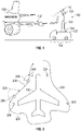
FIG. 1 depicts an example of a system for automated assessment of aircraft structure damage in conjunction with an aircraft. -
FIG. 2 depicts an example of a predetermined path around an aircraft. -
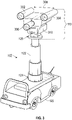
FIG. 3 depicts an example of an apparatus for automated assessment of aircraft structure damage. -
FIG. 4 depicts an example of a motorized table for an example of a system for automated assessment of aircraft structure damage. -
FIG. 5 depicts an example of a system for automated assessment of aircraft structure damage. -
FIG. 6 depicts an example of a first set of measurements taken over an exterior surface for determining a depth of a dent. -
FIG. 7 depicts an example of a second set of measurements taken over an exterior surface determining a depth of a dent. -
FIG. 8 depicts an example of a first set of measurements taken over an exterior surface for determining a width of a dent. -
FIG. 9 depicts an example of a second set of measurements taken over an exterior surface for determining a width of a dent. -
FIG. 10 depicts an example of an augmented reality image of a surface. -
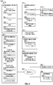
FIG. 11 is an operation flow chart for automated aircraft inspection during gate turnaround at airport. -
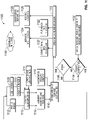
FIG. 12 is an inspection flow chart depicting an example of a method for automated assessment of aircraft structure damage. - While the disclosure is susceptible to various modifications and alternative forms, specific examples have been shown by way of example in the drawings and will be described in detail herein. However, it should be understood that the disclosure is not intended to be limited to the particular forms disclosed. Rather, the intention is to cover all modifications, equivalents and alternatives falling within the scope of the disclosure.
- Referring to
FIG. 1 , an example of asystem 100 for automated assessment of aircraft structure damage is depicted. Thesystem 100 may be used to assess anexterior surface 132 of anaircraft 130. Theexterior surface 132 of theaircraft 130 may include any externally visible portion of the aircraft that is capable of being assessed through imagery. - The
system 100 may include anapparatus 102 which may include acamera module 110 and anautonomous vehicle 120. Thecamera module 110 may be configured to capture both visible light and infrared imagery and/or videos. Theautonomous vehicle 120 may include a verticallyextendable arm 122, which may attach to theautonomous vehicle 120 at aproximal end 124 of the verticallyextendable arm 122, and which may attach to thecamera module 110 at adistal end 126 of the verticallyextendable arm 122. - During operation, the
autonomous vehicle 120 may be used to position thecamera module 110 to enable inspection of theaircraft 130. For example, theautonomous vehicle 120 may move to a position near theaircraft 130 and the verticallyextendable arm 122 may lift thecamera module 110 to a height sufficient to view theexterior surface 132 of theaircraft 130. - A benefit of the
system 100 is that ground inspections can be performed both above and below theaircraft 130. Further, since drone assisted aircraft inspections are generally prohibited at civil airports, performing a comprehensive surface inspection of the upper part ofaircraft 130 may be difficult. However, the verticallyextendable arm 122 may overcome this difficulty by enabling aerial views of theaircraft 130 similar to those that a drone may provide. Other benefits may exist as described herein. - Referring to
FIG. 2 , an example of apredetermined path 202 is depicted around anaircraft 130. Theautonomous vehicle 120, fromFIG. 1 , may be configured to move around theaircraft 130 according to thepredetermined path 202.Detectable references 204 positioned on a tarmac may assist theautonomous vehicle 120 in staying on thepredetermined path 202. For example, theautonomous vehicle 120 may include another camera and/or sensor to detect thedetectable references 204. In some cases, thecamera module 110 may be used to detect thedetectable references 204. Thedetectable references 204 may include dots, strips, reference waypoints, or combinations thereof placed on the tarmac. As an alternative to, or in addition to, thedetectable references 204, theautonomous vehicle 120 may be configured to use a stored electronic map, radar, lidar, a global positioning system, or a combination thereof to guide it along thepredetermined path 202. - While moving, the
autonomous vehicle 120 may be configured to use proximity range sensors to avoidobstacles 206. Examples of obstacles that theautonomous vehicle 120 may encounter include, but are not limited to, ground crew members, ground vehicles, and portions of theaircraft 130. Upon encountering theobstacles 206, theautonomous vehicle 120 may be configured to stop and wait until theobstacles 206 are removed or theautonomous vehicle 120 may be configured to plan and takedetour paths 208 to move around theobstacles 206. After following thedetour paths 208, theautonomous vehicle 120 may continue along thepredetermined path 202. - During the movement along the
predetermined path 202, thecamera module 110 may be configured to scan theexterior surface 132 of theaircraft 130. The scan may be used, as further described herein, to assess damage to theexterior surface 132, thereby providing a ground crew and a flight crew with sufficient data to make aircraft service and flight decisions. - Referring to
FIG. 3 , an example of anapparatus 102 for automated assessment of aircraft structure damage is depicted. Theapparatus 102 may include acamera module 110, anautomated vehicle 120, and a verticallyextendable arm 122. The verticallyextendable arm 122 may attach to theautomated vehicle 120 at aproximal end 124 of the verticallyextendable arm 122 and may attach to thecamera module 110 at adistal end 126 of the verticallyextendable arm 122. Thus, the verticallyextendable arm 122 may raise and lower thecamera module 110 as desired. - The
camera module 110 may include a firstinfrared camera 302, a secondinfrared camera 304, and a visiblelight camera 306. The firstinfrared camera 302 and the secondinfrared camera 304 may each be capable of infrared illumination using modulated continuous waves. Further, the modulated continuous waves associated with the firstinfrared camera 302 may be phase shifted to prevent interference with the modulated continuous waves associated with the secondinfrared camera 304. This may enable the first infrared camera and the second infrared camera to capture image data independent of each other. Further, the firstinfrared camera 302 and the secondinfrared camera 304 may each be capable of taking independent time-of-flight measurements using the modulated continuous waves having different phase shifts. These time-of-flight measurements may be used in generating a three-dimensional model of damaged portions of an aircraft as described further herein. - The
camera module 110 may further include a motorized table 310. The firstinfrared camera 302, the secondinfrared camera 304, and the visiblelight camera 306 may be attached to, or otherwise mounted on, the motorized table 310, such that they may be rotated in both azimuth and elevation by the motorized table 310. The firstinfrared camera 302 and the secondinfrared camera 304 may be separated by a fixeddistance 308 relative to one another to enable various measurements to be performed as described herein. - Referring to
FIG. 4 , an example of a motorized table 310 is depicted. The motorized table 310 may include a firstrotatable portion 402 to enable rotation in azimuth 0̸ and a secondrotatable portion 404 to enable rotation in elevation θ. The motorized table 310 may enable thecamera module 110 ofFIGS. 1 and3 to be directed at theexterior surface 132 from multiple directions. Changes of angles in both azimuth 0̸ and elevation θ ofFIG 4 enables thecamera module 110 to scan theexterior surface 132, or any particular area of interest. - Referring to
FIG. 5 , an example of asystem 100 for automated assessment of aircraft structure damage is depicted. As described herein, thesystem 100 may include acamera module 110 and anautonomous vehicle 120. Thecamera module 110 may include a firstinfrared camera 302, a secondinfrared camera 304, a visiblelight camera 306, and a motorized table 310. The firstinfrared camera 302 and the secondinfrared camera 304 may each be capable of infrared illumination using modulated continuous waves. For example, a first modulatedcontinuous wave 512 associated with the firstinfrared camera 302 may be phase shifted to prevent interference with a second modulated continuous wave 514 associated with the secondinfrared camera 304. In that way, the firstinfrared camera 302 and the secondinfrared camera 304 may each be capable of taking time-of-flight measurements 550 that are independent of each other. - The
autonomous vehicle 120 may include a verticallyextendable arm 122 coupled to thecamera module 110. Thevehicle 120 may further include aradar 522, alidar 524, aglobal positioning system 526, and/or combinations thereof to assist thevehicle 120 in following thepredetermined path 202 ofFIG. 2 . Theautonomous vehicle 120 may also includeproximity range sensors 528 to assist thevehicle 120 with avoiding theobstacles 206 ofFIG. 2 . - The
system 100 may include acontrol module 530 for controlling theautonomous vehicle 120 and for processing data as described herein. Thecontrol module 530 may be part of theautonomous vehicle 120, or it may be separate from theautonomous vehicle 120 and may perform control functions remotely. In some cases, thecontrol module 530 may be distributed between theautonomous vehicle 120 and one or more remote devices. - The
control module 530 may include aprocessor 532. As used herein, theprocessor 532 may include a microcontroller, a central processing unit (CPU), a graphical processing unit (GPU), a digital signal processor (DSP), a peripheral interface controller (PIC), another type of microprocessor, and/or combinations thereof. Further, theprocessor 532 may be implemented as an integrated circuit, a complementary metal-oxide-semiconductor (CMOS) metal-oxide-semiconductor field-effect-transistor (MOSFET) circuit, a very-large-scale-integrated (VLSI) circuit, a field-programmable gate array (FPGA), an application-specific integrated circuit (ASIC), a combination of logic gate circuitry, another type of digital or analog electrical design component, or combinations thereof. For purposes of this disclosure, theprocessor 532 may further comprise memory sufficient to perform the functions described herein. The memory may include memory devices such as random-access memory (RAM), read-only memory (ROM), magnetic disk memory, optical disk memory, flash memory, another type of memory capable of storing data and processor instructions, or the like, or combinations thereof. - The
system 100 may include amobile device 562 and adatabase 564 coupled to thecontrol module 530 via anetwork connection 560. Themobile device 562 may be, but is not limited to, a laptop device, a tablet device, an electronic flight book, or another type of personal computing device. Themobile device 562 may be associated with a ground crew member, a flight crew member, or another member of a group charged with assessing an aircraft. - During operation, the
processor 532 may initiate movement of theautonomous vehicle 120 around an aircraft (e.g., the aircraft 130) according to apredetermined path 202. Before initiating the movement, theprocessor 532 may plan the movement of theautonomous vehicle 120 using a storedelectronic map 534. As theautonomous vehicle 120 moves, theprocessor 532 may verify the movement of theautonomous vehicle 120 using detectable references (e.g., the detectable references 204) positioned on a tarmac. The movement may also be verified through the use of theradar 522, thelidar 524, theglobal positioning system 526, or a combination thereof. Further, theprocessor 532 may receive input from theproximity range sensors 528 to avoid obstacles (e.g., the obstacles 206) during the movement of theautonomous vehicle 120 around theaircraft 130. - While the
autonomous vehicle 120 moves around theaircraft 130, theprocessor 532 may initiate ascan 536 of anexterior surface 132 of theaircraft 130 using the firstinfrared camera 302, the secondinfrared camera 304, the visiblelight camera 306, or a combination thereof. In some cases, thescan 536 may be made using the visiblelight camera 306 and theprocessor 532 may rely on visual image processing techniques to analyze thescan 536. In this way, theprocessor 532 may determine whether a portion of theexterior surface 132 of theaircraft 130 is damaged. - In response to determining that damage exists, the
control module 530 may receive the time-of-flight measurements 550,visible image data 552, andinfrared image data 556 from thecamera module 110. Theprocessor 532 may use the time-of-flight measurements 550 to generate a three-dimensional model 542 of the damage. Theprocessor 532 may also generate an augmented reality image orvideo 544 based on the three-dimensional model 542, thevisible image data 552, theinfrared image data 556, or combinations thereof. The augmented reality image orvideo 544 may be used to aid crews in making flight decisions. - Various processes may be applied to the
visible image data 552 and theinfrared image data 556 to improve its usefulness for flight and ground crews. For example, thevisible image data 552 may initially include discrepancies due tolighting conditions 554. Theprocessor 532 may enhance thevisible image data 552 generated by the visiblelight camera 306 by using agrayscale conversion 540 to remove the discrepancies due tolighting conditions 554. As another example, theinfrared image data 556 may include an ambientbackground light component 558. Theprocessor 532 may perform adifferential measurement process 538 using thevisible image data 552 from the visiblelight camera 306 to remove the ambientbackground light component 558. Thedifferential measurement process 538 may differentiate thevisible image data 552 taken by the visiblelight camera 306 and theinfrared image data 556 and reveal infrared-only content. The resulting content is without the effects of the ambientbackground light component 558 which may contribute to errors such as bias, shift, and offset. Based on measured pixel intensity, phase angles between illumination and reflection and a distance between the imaging sensor and an object can be calculated. - The
control module 530 may be configured to provide a live image orvideo 545 from the visiblelight camera 306 to amobile device 562 via anetwork connection 560. This may enable a flight crew or a ground crew to view thescan 536 in real time. Further, thecontrol module 530 may be configured to provide the three-dimensional model 542 to themobile device 562 for rendering via thenetwork connection 560. The three-dimensional model 542 may be superimposed with the augmented reality image orvideo 544. Thecontrol module 530 may provide the three-dimensional model 542 to thedatabase 564. Thedatabase 564 may store previous three-dimensional models 568 to use for comparison. Thus, the three-dimensional model 542 may be stored for use in comparisons to future three-dimensional models. Thecontrol module 530 may further provide a damage assessment to themobile device 562 to assist a crew, an airline, or both in making flight decisions. - A benefit of the
system 100 is that aircraft inspections may be automated and efficiency of flight crews and ground crews in making damage assessments can be increased. Additionally, by maintaining thedatabase 564, more data for analytics may be generated. Other benefits may exist. - Referring to
FIG. 6 , an example of a first set of measurements taken over anexterior surface 132 for determining a depth of adent 602 is depicted. The measurements depicted may be taken in response to a determination that aportion 601 of the exterior surface 132 (e.g., of the aircraft 130) is damaged. - In order to determine the depth and/or shape of the
dent 602, abase line 610 between a first point 622 (which may be associated with the firstinfrared camera 302 ofFIGS. 3 and5 ) and a second point 624 (which may be associated with the secondinfrared camera 304 ofFIGS. 3 and5 ) may be made parallel with theportion 601 of theexterior surface 132. In order to position thebase line 610 in a parallel configuration, theautonomous vehicle 120 ofFIGS. 1 ,3 , and5 may be moved. In particular, theprocessor 532 may initiate movement of theautonomous vehicle 120. - The first
infrared camera 302 and the secondinfrared camera 304 camera may be rotated so that the firstinfrared camera 302 and the secondinfrared camera 304 are directed to astarting point 604 of thedent 602. As shown inFIG. 6 , a first angle ofazimuth 614 may be determined at thefirst point 622 based on an angle of rotation of the firstinfrared camera 302. A second angle ofazimuth 618 may be determined at thesecond point 624 based on an angle of rotation of the secondinfrared camera 304. Adistance 626 between thefirst point 622 and thesecond point 624 may be fixed. Adistance 620 between thebase line 610 and thestarting point 604 may be determined based on the following formula:
distance 620 between thebase line 610 and thepoint 604, d is thedistance 626 between thefirst point 622 and the second point 624 (e.g., between the firstinfrared camera 302 and the second infrared camera 304), α is the first angle inazimuth 614, and β is the second angle inazimuth 618. Since thedistance 626 between the two infrared cameras is known, the process may be iteratively repeated for multiple points, such as at least oneintermediate point 606, up to anending point 608. The process may be repeated along a full plane associated with theexterior surface 132 to map out depths and shape of thedent 602. - Referring to
FIG. 7 , an example of a second set of measurements taken over theportion 601 of theexterior surface 132 for determining a depth of thedent 602 is depicted. InFIG. 7 , the firstinfrared camera 302 and the secondinfrared camera 304 may be rotated so that the firstinfrared camera 302 and the secondinfrared camera 304 are directed to theintermediate point 606. In this state, the first angle inazimuth 614 at thefirst point 622 has been reduced relative toFIG. 6 and the second angle inazimuth 618 at thesecond point 624 has been increased relative toFIG. 6 . Because theintermediate point 606 is deeper within theportion 601 of theexterior surface 132, adistance 620 between thebase line 610 and theintermediate point 606 may be increased relative toFIG. 6 . Thedistance 620 may be determined as described with reference toFIG. 6 based on the first angle inazimuth 614, the second angle inazimuth 618, and the fixeddistance 626 between thefirst point 622 and thesecond point 624. - As described with respect to
FIGS. 6 and 7 , for each point (e.g., thestarting point 604, theintermediate point 606, and the ending point 608) of a set of points running along thedent 602, a first angle inazimuth 614 associated with the firstinfrared camera 302 and a second angle inazimuth 618 associated with the secondinfrared camera 304 may be determined. Distances between thebase line 610 and the points running along thedent 602 may be calculated using the first angle inazimuth 614 and the second angle inazimuth 618 for each point. This process may be repeated for incremental changes of elevation angle θ ofFIG 4 to scan the entire area of thedent 602. Distances (e.g., the distance 620) between thebase line 610 and the points may be used to generate the three-dimensional model 542 mapping out the depth and shape of thedent 602. - Referring to
FIG. 8 , an example of a first set of measurements taken over aportion 601 of anexterior surface 132 for determining awidth 840 of adent 602 is depicted. Thewidth 840 can be determined using multiple different measurements, one of which is depicted inFIG. 8 and another of which is depicted inFIG. 9 . - In
FIG. 8 , a first time-of-flight measurement may be used to determine afirst distance 812 between thefirst point 622 associated with the firstinfrared camera 302 and astarting point 802 of thedent 602. Asecond distance 828 between thefirst point 622 and anending point 804 of thedent 602 may be determined using a second time-of-flight measurement. An angle inazimuth 814 between afirst direction 813 associated with the firstinfrared camera 302 being directed at thestarting point 802 of thedent 602 and asecond direction 829 associated with the firstinfrared camera 302 being directed at theending point 804 may be determined. Thewidth 840 may be trigonometrically calculated through the law of cosines based on thefirst distance 812, thesecond distance 828, and the angle ofazimuth 814. In other words,
width 840 between thestarting point 802 and theending point 804, α is thedistance 812 between thefirst point 622 and thestarting point 802; b is thedistance 828 between thefirst point 622 and theending point 804, and γ is the angle ofazimuth 814. - The second
infrared camera 304 associated with thesecond point 624 may be used to confirm thewidth 840. For example, thewidth 840 may be trigonometrically verified based on athird distance 830 between thesecond point 624 and thestarting point 802, afourth distance 816 between thesecond point 624 and theending point 804, and another angle inazimuth 818 associated with thesecond point 624. - Referring to
FIG. 9 , an example of a second set of measurements taken over theportion 601 of theexterior surface 132 for determining thewidth 840 of thedent 602 is depicted. In the case ofFIG. 9 , the process may be performed after movement of theautonomous vehicle 120 to position the firstinfrared camera 302 and the secondinfrared camera 304 so that abase line 610 between the firstinfrared camera 302 and the secondinfrared camera 304 is parallel with theportion 601 of theexterior surface 132. - In
FIG. 9 , afirst distance 812 between thefirst point 622 associated with the firstinfrared camera 302 and astarting point 802 of thedent 602 may be determined using a first time-of-flight measurement. Asecond distance 928 between thefirst point 622 and anending point 804 of thedent 602 may be determined using a second time-of-flight measurement. Athird distance 930 between thesecond point 624 and thestarting point 802 may be determined using a third time-of-flight measurement. Afourth distance 816 between thesecond point 624 and theending point 804 may be determined using a fourth time-of-flight measurement. Under this condition that thecamera module 110 is in parallel with theportion 601, a quadrilateral based on thedistances width 840 of thedent 602 may be determined in an alternative method that is based solely on distance measurements, without azimuth angle involved.
same width 840 between thestarting point 802 and theending point 804; α is thesame distance 812 between thefirst point 622 and thestarting point 802; c is thedistance 928 between thefirst point 622 and theending point 804; g is thedistance 930 between thesecond point 624 and thestarting point 802; e is thedistance 816 between thesecond point 624 and theending point 804; f is thedistance 626 between thefirst point 622 and thesecond point 624, i.e., the separation between two infrared cameras oncamera module 110. - By scanning the
camera module 110 azimuthally at every incremental change of the elevation angles inFIG 4 , depths and widths of thedent 602 are determined, and a three-dimensional model 542 ofFIG. 5 may be generated. Further, the augmented reality image orvideo 544 may be generated based on the three-dimensional model 542. - Referring to
FIG. 10 , an example of an augmented reality image orvideo 1000 is depicted. The augmented image orvideo 1000 may include a visible image orvideo 1002 superimposed with a mesh or agrid 1004 representing damage information. For example, as depicted inFIG. 10 ,depth numbers 1006 may be present along thegrid 1004 to indicate the contour and/or shape of damage depicted in the image orvideo 1002. The augmented reality image orvideo 1000 may enable a flight crew member or a ground crew member to make an accurate assessment of the effect the damage may have on a flight. Additional flight decisions may then be made accordingly. - Referring to
FIG. 11 , an example of amethod 1100 for automated assessment of aircraft structure damage is depicted. Themethod 1100 may include performing a drive-around inspection with videos and images, at 1102. For example, theautonomous vehicle 120 may be configured to follow thepredetermined path 202 while thecamera module 110 generates photos and videos. Then, a determination as to whether damage is suspected may be made at 1104. - If no damage is suspected at 1104, then the
method 1100 may continue with the drive-around inspection, at 1102, until the inspection is done at 1106. If the inspection is done, then the results may be submitted to a crew and airline for making a flight decision, at 1118. If damage is suspected, at 1104, then images may be obtained, as described herein. Aphoto image 1112 may be obtained, for example, by using the visiblelight camera 306 ofFIGS. 3 and5 . A left infrared image may be taken at 1108 and a right infrared image may be taken at 1110. The firstinfrared camera 302 and the secondinfrared camera 304 may be used. Based on the images, damage classification may be performed, at 1113. In order to classify the damage, previously generated data (such as previous models, images, videos, etc.) may be retrieved from adatabase 1130 which may be cloud-based. Further, grayscale enhancement may be performed at 1111 to enable comparison between the photo image taken at 1112 and data from thedatabase 1130. For example, the grayscale enhancement performed at 1111 may compensate for lighting under differing lighting conditions. - After the damage has been classified at 1113, an ambient background removal process may be performed at 1114. The ambient background removal process may remove a visible light component from the infrared images taken at 1108, 1110. Once the ambient background removal has taken place at 1114, three-dimensional dimensions, such as depths and widths, of the damage may be extracted, at 1116. An augmented reality display may be generated at 1119 and combined with dimensions that were extracted at 1116. At 1118, the crew and airline decision may be made based on the augmented reality display. Examples of decisions that may be made include a conditional minimal equipment list (MEL) departure, at 1120, a service notification at 1124, or pushback and departure at 1122. This list is non-exhaustive and other decisions may be made by the crew and airline based on existing flight standards. A record may be entered into a logbook, at 1126, noting the damage and the decision made at 1118. Further, reporting of damages and findings considered confidential to airlines may be made anonymously at 1128. These items may be stored in the
database 1130 for later use. - As shown in
FIG. 11 , thesystem 100 and its associated processes may be incorporated into existing decision-making processes used by flight crews and ground crews to assist decision makers in their assignments. The automated process may ensure a more thorough inspection and better decision outcomes. Other benefits may exist. - Referring to
FIG. 12 , an example of amethod 1200 for making aircraft service decisions and incorporating automated assessment of aircraft structure damage is depicted. Themethod 1200 may include moving an autonomous vehicle around an aircraft according to a predetermined path, where the autonomous vehicle includes a vertically extendable arm, where a camera module is attached to a distal end of the vertically extendable arm, and where the camera module includes a first infrared camera, a second infrared camera, and a visible light camera, at 1202. For example, theautonomous vehicle 120 may move around theaircraft 130 according to thepredetermined path 202. - The
method 1200 may further include scanning an exterior surface of the aircraft using the first infrared camera, the second infrared camera, the visible light camera, or a combination thereof, at 1204. For example, theexterior surface 132 may be scanned using the firstinfrared camera 302, the secondinfrared camera 304, the visiblelight camera 306, or a combination thereof as theautonomous vehicle 120 moves around theaircraft 130. - The
method 1200 may also include determining whether a portion of the exterior surface of the aircraft is damaged based on the scan, at 1206. For example, theprocessor 532 may determine whether theportion 601 of theexterior surface 132 of theaircraft 130 is damaged based on thescan 536, which may be taken while theautonomous vehicle 120 moves. - The
method 1200 may also include, in response to the portion of the exterior surface of the aircraft being damaged, using the first infrared camera, the second infrared camera, and the visible light camera to generate a three-dimensional model of the portion of the exterior surface of the aircraft, at 1208. For example, the firstinfrared camera 302, the secondinfrared camera 304, and the visiblelight camera 306 may be used to generate the three-dimensional model 542 of the damage. - The
method 1200 may include additional sub-processes for generating the three-dimensional model. For example, themethod 1200 may include initiating movement of the autonomous vehicle to position the first infrared camera and the second infrared camera so that a base line between the first infrared camera and the second infrared camera is parallel with the portion of the exterior surface of the aircraft, at 1210. For example, theautonomous vehicle 120 may be positioned such that thebase line 610 between the first point 622 (associated with the first infrared camera 302) and the second point 624 (associated with the second infrared camera 304) is parallel with theportion 601 of theexterior surface 132 of theaircraft 130. - The
method 1200 may further include rotating the first infrared camera and the second infrared camera so that the first infrared camera and the second infrared camera are iteratively directed at points running along a dent in the portion of the exterior surface of the aircraft beginning at a starting point on a first side of the dent and ending at an ending point on a second side of the dent, at 1212. For example, the firstinfrared camera 302 and the secondinfrared camera 304 may be iteratively directed at thestarting point 604, theintermediate point 606, and theending point 608. Additional intermediate points may also exist. - The
method 1200 may also include, for each point of the points running along the dent, determining a first angle in azimuth associated with the first infrared camera and a second angle in azimuth associated with the second infrared camera, at 1214. For example, the first angle inazimuth 614 and the second angle inazimuth 618 may be determined. - The
method 1200 may include calculating distances between the base line and the points running along the dent using the first angle in azimuth and the second angle in azimuth for each point of the points, where the distances between the base line and the points running along the dent are used to generate the three-dimensional model of the portion of the exterior surface of the aircraft, at 1216. For example, based on the first angle inazimuth 614 and the second angle inazimuth 618, thedistance 620 between thebase line 610 and thepoints distance 626 between thefirst point 622 and thesecond point 624. - The
method 1200 may include determining a first distance between the first infrared camera and the starting point of the dent in the portion of the exterior surface of the aircraft using a first time-of-flight measurement, at 1218. For example, the firstinfrared camera 302 may use a time-of-flight measurement to determine adistance 812 between thefirst point 622 and thestarting point 802. - The
method 1200 may further include determining a second distance between the first infrared camera and the ending point of the dent using a second time-of-flight measurement, at 1220. For example, the firstinfrared camera 302 may use a time-of-flight measurement to determine adistance 828 between thefirst point 622 and theending point 804. - The
method 1200 may include calculating a width between the starting point of the dent and the ending point of the dent based at least partially on the first distance and the second distance, at 1222. For an example ofFIG 8 , thedistance 812 between thefirst point 622 and thestarting point 802 and thedistance 828 between thefirst point 622 and theending point 804 may be used, among other parameters, to determine thewidth 840 of thedent 602. In some cases, the other parameters may include the first angle inazimuth 814. In some cases, the other calculated parameters may include thedistance 816 of eitherFIGS 8 or 9 between thesecond point 624 and theending point 804, thedistance 830 inFIG 8 or thedistance 930 inFIG 9 between thesecond point 624 and thestarting point 802, and thedistance 626 inFIG 9 between thefirst point 622 and thesecond point 624. - An advantage of the
method 1200 is that by scanningcamera module 110 azimuthally at incremental change of the elevation angles inFIG 4 , with the help of computational algorithms and augmented reality, a three-dimensional model may be generated to enable a ground crew and/or flight crew to efficiently and effectively inspect an aircraft and make flight decisions based on the inspection. Other advantages may exist. - Further, the disclosure comprises examples according to the following clauses:
- Clause 1. An automated system comprising:
- a camera module comprising:
- a first infrared camera;
- a second infrared camera; and
- a visible light camera;
- an autonomous vehicle comprising a vertically extendable arm, wherein the camera module is attached to a distal end of the vertically extendable arm; and
- a processor configured to:
- initiate movement of the autonomous vehicle around an aircraft according to a predetermined path;
- initiate a scan of an exterior surface of the aircraft using the first infrared camera, the second infrared camera, the visible light camera, or a combination thereof;
- in response to the portion of the exterior surface of the aircraft being damaged, use the first infrared camera, the second infrared camera, and the visible light camera to compute dimensional parameters of damage to the exterior surface and generate a three-dimensional model of the portion of the exterior surface of the aircraft.
- a camera module comprising:
-
Clause 2. The system of Clause 1, wherein the camera module further comprises a motorized table configured to rotate in both azimuth and elevation, wherein the first infrared camera, the second infrared camera, and the visible light camera are attached to the motorized table, wherein the first infrared camera and the second infrared camera are separated by a fixed distance relative to one another, and wherein initiating the scan of the exterior surface of the aircraft comprises commanding the camera module to scan azimuthally at incremental changes of elevation angles. -
Clause 3. The system ofClauses 1 or 2, wherein the processor is further configured to:- plan the movement of the autonomous vehicle around the aircraft using a stored electronic map; and
- verify the movement of the autonomous vehicle using detectable references positioned on a tarmac, a radar, a lidar, a global positioning system, or a combination thereof.
-
Clause 4. The system of any one of Clauses 1-3, wherein the autonomous vehicle is configured to use proximity range sensors to avoid obstacles during the movement of the autonomous vehicle around the aircraft. -
Clause 5. The system of any one of Clauses 1-4, wherein the first infrared camera and the second infrared camera are each capable of infrared illumination using modulated continuous waves, wherein a modulated continuous wave associated with the first infrared camera is phase shifted to prevent interference with a modulated continuous wave associated with the second infrared camera, wherein the first infrared camera and the second infrared camera are each capable of taking independent time-of-flight measurements using the modulated continuous waves, and wherein the independent time-of-flight measurements are used in generating the three-dimensional model of the portion of the exterior surface. -
Clause 6. The system of any one of Clauses 1-5, wherein the processor is further configured to perform a differential measurement process using visible image data from the visible light camera to remove an ambient background light component from infrared image data received from the first infrared camera and the second infrared camera. - Clause 7. The system of any one of Clauses 1-6, wherein, in response to the portion of the exterior surface of the aircraft being damaged, the processor is further configured to:
- initiate movement of the autonomous vehicle to position the first infrared camera and the second infrared camera so that a base line between the first infrared camera and the second infrared camera is parallel with the portion of the exterior surface of the aircraft;
- rotate the first infrared camera and the second infrared camera so that the first infrared camera and the second infrared camera are iteratively directed at points running along a dent in the portion of the exterior surface of the aircraft beginning at a starting point on a first side of the dent and ending at an ending point on a second side of the dent;
- for each point of the points running along the dent, determine a first angle in azimuth associated with the first infrared camera and a second angle in azimuth associated with the second infrared camera; and
- calculate distances between the base line and the points running along the dent using the first angle in azimuth and the second angle in azimuth for each point of the points, wherein the distances between the base line and the points running along the dent are used to generate the three-dimensional model of the portion of the exterior surface of the aircraft.
- Clause 8. The system of any one of Clauses 1-7, wherein, in response to the portion of the exterior surface of the aircraft being damaged, the processor is further configured to:
- determine a first distance between the first infrared camera and a starting point of a dent in the portion of the exterior surface of the aircraft using a first time-of-flight measurement;
- determine a second distance between the first infrared camera and an ending point of the dent using a second time-of-flight measurement;
- determine an angle in azimuth between a first direction associated with the first infrared camera being directed at the starting point of the dent and a second direction associated with the first infrared camera being directed at the ending point; and
- calculate a width between the starting point of the dent and the ending point of the dent based on the first distance, the second distance, and the angle in azimuth.
- Clause 9. The system of Clause 8, wherein, in response to the portion of the exterior surface of the aircraft being damaged, the processor is further configured to:
use the second infrared camera to confirm the width between the starting point of the dent and the ending point of the dent. - Clause 10. The system of any one of Clauses 1-7, wherein, in response to the portion of the exterior surface of the aircraft being damaged, the processor is further configured to:
- initiate movement of the autonomous vehicle to position the first infrared camera and the second infrared camera so that a base line between the first infrared camera and the second infrared camera is parallel with the portion of the exterior surface of the aircraft;
- determine a first distance between the first infrared camera and a starting point of a dent in the portion of the exterior surface of the aircraft using a first time-of-flight measurement;
- determine a second distance between the first infrared camera and an ending point of the dent using a second time-of-flight measurement;
- determine a third distance between the second infrared camera and the starting point of the dent using a third time-of-flight measurement;
- determine a fourth distance between the second infrared camera and the ending point of the dent using a fourth time-of-flight measurement; and
- calculate a width between the starting point of the dent and the ending point of the dent based on the first distance, the second distance, the third distance, the fourth distance, and a fifth distance between the first infrared camera and the second infrared camera.
- Clause 11. The system of any one of Clauses 1-10, wherein the processor is further configured to produce an augmented reality image or video that superimposes dimensional parameters from the three-dimensional model onto an image or video of the portion of the exterior surface of the aircraft.
- Clause 12. The system of any one of Clauses 1-11, wherein the processor is further configured to enhance visible image data generated by the visible light camera by using a grayscale conversion to remove discrepancies due to lighting conditions.
- Clause 13. The system of any one of Clauses 1-12, wherein the processor is further configured to provide a live image or video from the visible light camera to a mobile device via a network connection.
- Clause 14. The system of any one of Clauses 1-13, wherein the processor is further configured to provide the three-dimensional model to a mobile device for rendering via a network connection.
- Clause 15. The system of any one of Clauses 1-14, wherein the processor is further configured to provide a damage assessment to a mobile device to assist a crew, an airline, or both in making flight decisions.
- Clause 16. The system of any one of Clauses 1-15, further comprising a database, wherein the processor is further configured to provide the three-dimensional model to the database for use in comparisons to future three-dimensional models associated with the portion of the exterior surface, to provide findings related to damage to the exterior surface to the database for documentation, or both.
- Clause 17. A method comprising:
- moving an autonomous vehicle around an aircraft according to a predetermined path, wherein the autonomous vehicle comprises a vertically extendable arm, wherein a camera module is attached to a distal end of the vertically extendable arm, and wherein the camera module comprises a first infrared camera, a second infrared camera, and a visible light camera;
- scanning an exterior surface of the aircraft using the first infrared camera, the second infrared camera, the visible light camera, or a combination thereof;
- determining whether a portion of the exterior surface of the aircraft is damaged based on the scan; and
- in response to the portion of the exterior surface of the aircraft being damaged, using the first infrared camera, the second infrared camera, and the visible light camera to generate a three-dimensional model of the portion of the exterior surface of the aircraft.
- Clause 18. The method of Clause 17, further comprising:
- initiating movement of the autonomous vehicle to position the first infrared camera and the second infrared camera so that a base line between the first infrared camera and the second infrared camera is parallel with the portion of the exterior surface of the aircraft;
- rotating the first infrared camera and the second infrared camera so that the first infrared camera and the second infrared camera are iteratively directed at points running along a dent in the portion of the exterior surface of the aircraft beginning at a starting point on a first side of the dent and ending at an ending point on a second side of the dent;
- for each point of the points running along the dent, determining a first angle in azimuth associated with the first infrared camera and a second angle in azimuth associated with the second infrared camera; and
- calculating distances between the base line and the points running along the dent using the first angle in azimuth and the second angle in azimuth for each point of the points, wherein the distances between the base line and the points running along the dent are used to generate the three-dimensional model of the portion of the exterior surface of the aircraft.
- Clause 19. The method of Clauses 17 or 18, further comprising:
- determining a first distance between the first infrared camera and a starting point of a dent in the portion of the exterior surface of the aircraft using a first time-of-flight measurement;
- determining a second distance between the first infrared camera and an ending point of the dent using a second time-of-flight measurement; and
- calculating a width between the starting point of the dent and the ending point of the dent based, at least in part, on the first distance and the second distance.
- Clause 20. An apparatus comprising:
- a camera module comprising:
- a first infrared camera;
- a second infrared camera; and
- a visible light camera; and
- an autonomous vehicle comprising a vertically extendable arm, wherein the camera module is attached to a distal end of the vertically extendable arm, wherein the autonomous vehicle is configured to move around an aircraft according to a predetermined path, and wherein the camera module is configured to scan of an exterior surface of the aircraft using the first infrared camera, the second infrared camera, the visible light camera, or a combination thereof.
- a camera module comprising:
- Although various examples have been shown and described, the present disclosure is not so limited and will be understood to include all such modifications and variations as would be apparent to one skilled in the art.
Claims (15)
- An automated system (100) comprising:a camera module (110) comprising:a first infrared camera (302);a second infrared camera (304); anda visible light camera (306);an autonomous vehicle (120) comprising a vertically extendable arm (122), wherein the camera module (110) is attached to a distal end (126) of the vertically extendable arm (122); anda processor (532) configured to:initiate movement of the autonomous vehicle (120) around an aircraft (130) according to a predetermined path (202);initiate a scan of an exterior surface (132) of the aircraft (130) using the first infrared camera (302), the second infrared camera (304), the visible light camera (306), or a combination thereof;in response to a portion (601) of the exterior surface (132) of the aircraft (130) being damaged, use the first infrared camera (302), the second infrared camera (304), and the visible light camera (306) to compute dimensional parameters of damage to the exterior surface (132) and generate a three-dimensional model of the portion (601) of the exterior surface (132) of the aircraft (130).
- The automated system (100) of claim 1, wherein the camera module (110) further comprises a motorized table (310) configured to rotate in both azimuth and elevation, wherein the first infrared camera (302), the second infrared camera (304), and the visible light camera (306) are attached to the motorized table (310), wherein the first infrared camera (302) and the second infrared camera (304) are separated by a fixed distance (308) relative to one another, and wherein initiating the scan of the exterior surface (132) of the aircraft (130) comprises commanding the camera module (110) to scan azimuthally at incremental changes of elevation angles.
- The automated system (100) of claims 1 or 2, wherein the processor (532) is further configured to:plan the movement of the autonomous vehicle (120) around the aircraft (130) using a stored electronic map (534); andverify the movement of the autonomous vehicle (120) using detectable references (204) positioned on a tarmac, a radar (522), a lidar (524), a global positioning system (526), or a combination thereof.
- The automated system (100) of any one of claims 1-3, wherein the autonomous vehicle (120) is configured to use proximity range sensors (528) to avoid obstacles (206) during the movement of the autonomous vehicle (120) around the aircraft (130).
- The automated system (100) of any one of claims 1-4, wherein the first infrared camera (302) and the second infrared camera (304) are each capable of infrared illumination using modulated continuous waves, wherein a modulated continuous wave (512) associated with the first infrared camera (302) is phase shifted to prevent interference with a modulated continuous wave (514) associated with the second infrared camera (304), wherein the first infrared camera (302) and the second infrared camera (304) are each capable of taking independent time-of-flight measurements (550) using the modulated continuous waves (512, 514), and wherein the independent time-of-flight measurements (550) are used in generating the three-dimensional model of the portion (601) of the exterior surface (132).
- The automated system (100) of any one of claims 1-5, wherein the processor (532) is further configured to perform a differential measurement process using visible image data (552) from the visible light camera (306) to remove an ambient background light component (558) from infrared image data (556) received from the first infrared camera (302) and the second infrared camera (304).
- The automated system (100) of any one of claims 1-6, wherein, in response to the portion (601) of the exterior surface (132) of the aircraft (130) being damaged, the processor (532) is further configured to:initiate movement of the autonomous vehicle (120) to position the first infrared camera (302) and the second infrared camera (304) so that a base line (610) between the first infrared camera (302) and the second infrared camera (304) is parallel with the portion (601) of the exterior surface (132) of the aircraft (130);rotate the first infrared camera (302) and the second infrared camera (304) so that the first infrared camera (302) and the second infrared camera (304) are iteratively directed at points running along a dent (602) in the portion (601) of the exterior surface (132) of the aircraft (130) beginning at a starting point (604) on a first side of the dent (602) and ending at an ending point (608) on a second side of the dent (602);for each point of the points running along the dent (602), determine a first angle in azimuth (614) associated with the first infrared camera (302) and a second angle in azimuth (618) associated with the second infrared camera (304); andcalculate distances between the base line (610) and the points running along the dent (602) using the first angle in azimuth (614) and the second angle in azimuth (618) for each point of the points, wherein the distances between the base line (610) and the points running along the dent (602) are used to generate the three-dimensional model of the portion (601) of the exterior surface (132) of the aircraft (130).
- The automated system (100) of any one of claims 1-7, wherein, in response to the portion (601) of the exterior surface (132) of the aircraft (130) being damaged, the processor (532) is further configured to:determine a first distance (812) between the first infrared camera (302) and a starting point (802) of a dent (602) in the portion (601) of the exterior surface (132) of the aircraft (130) using a first time-of-flight measurement;determine a second distance (828) between the first infrared camera (302) and an ending point (804) of the dent (602) using a second time-of-flight measurement;determine an angle in azimuth (814) between a first direction (813) associated with the first infrared camera (302) being directed at the starting point (802) of the dent (602) and a second direction (829) associated with the first infrared camera (302) being directed at the ending point (804); andcalculate a width (840) between the starting point (802) of the dent (602) and the ending point (804) of the dent (602) based on the first distance (812), the second distance (828), and the angle in azimuth (814).
- The automated system (100) of any one of claims 1-7, wherein, in response to the portion (601) of the exterior surface (132) of the aircraft (130) being damaged, the processor (532) is further configured to:initiate movement of the autonomous vehicle (120) to position the first infrared camera (302) and the second infrared camera (304) so that a base line (610) between the first infrared camera (302) and the second infrared camera (304) is parallel with the portion (601) of the exterior surface (132) of the aircraft (130);determine a first distance (812) between the first infrared camera (302) and a starting point (802) of a dent (602) in the portion (601) of the exterior surface (132) of the aircraft (130) using a first time-of-flight measurement;determine a second distance (928) between the first infrared camera (302) and an ending point (804) of the dent (602) using a second time-of-flight measurement;determine a third distance (930) between the second infrared camera (302) and the starting point (802) of the dent (602) using a third time-of-flight measurement;determine a fourth distance (816) between the second infrared camera (304) and the ending point (804) of the dent (602) using a fourth time-of-flight measurement; andcalculate a width (840) between the starting point (802) of the dent (602) and the ending point (804) of the dent (602) based on the first distance (812), the second distance (928), the third distance (930), the fourth distance (816), and a fifth distance (626) between the first infrared camera (302) and the second infrared camera (304).
- The automated system (100) of any one of claims 1-9, wherein the processor (532) is further configured to produce an augmented reality image or video (1000) that superimposes dimensional parameters from the three-dimensional model onto an image or video of the portion (601) of the exterior surface (132) of the aircraft (130).
- The automated system (100) of any one of claims 1-10, wherein the processor (532) is further configured to enhance visible image data generated by the visible light camera 306) by using a grayscale conversion (540) to remove discrepancies due to lighting conditions (554).
- A method (1200) comprising:moving an autonomous vehicle around an aircraft according to a predetermined path, wherein the autonomous vehicle comprises a vertically extendable arm, wherein a camera module is attached to a distal end of the vertically extendable arm, and wherein the camera module comprises a first infrared camera, a second infrared camera, and a visible light camera (1202);scanning an exterior surface of the aircraft using the first infrared camera, the second infrared camera, the visible light camera, or a combination thereof (1204);determining whether a portion of the exterior surface of the aircraft is damaged based on the scan (1206); andin response to the portion of the exterior surface of the aircraft being damaged, using the first infrared camera, the second infrared camera, and the visible light camera to generate a three-dimensional model of the portion of the exterior surface of the aircraft (1208).
- The method (1200) of claim 12, further comprising:initiating movement of the autonomous vehicle to position the first infrared camera and the second infrared camera so that a base line between the first infrared camera and the second infrared camera is parallel with the portion of the exterior surface of the aircraft (1210);rotating the first infrared camera and the second infrared camera so that the first infrared camera and the second infrared camera are iteratively directed at points running along a dent in the portion of the exterior surface of the aircraft beginning at a starting point on a first side of the dent and ending at an ending point on a second side of the dent (121);for each point of the points running along the dent, determining a first angle in azimuth associated with the first infrared camera and a second angle in azimuth associated with the second infrared camera (1214); andcalculating distances between the base line and the points running along the dent using the first angle in azimuth and the second angle in azimuth for each point of the points, wherein the distances between the base line and the points running along the dent are used to generate the three-dimensional model of the portion of the exterior surface of the aircraft (1216).
- The method (1200) of claims 12 or 13, further comprising:determining a first distance between the first infrared camera and a starting point of a dent in the portion of the exterior surface of the aircraft using a first time-of-flight measurement (1218);determining a second distance between the first infrared camera and an ending point of the dent using a second time-of-flight measurement (1220); andcalculating a width between the starting point of the dent and the ending point of the dent based, at least in part, on the first distance and the second distance (1222).
- An apparatus (102) comprising an automated system (100) according to any one of the claims 1 to 11, wherein the autonomous vehicle (120) of the automated system (100) is configured to move around an aircraft (130) according to a predetermined path (202), and wherein the camera module (110) is configured to scan of an exterior surface (132) of the aircraft (130) using the first infrared camera (302), the second infrared camera (304), the visible light camera (306), or a combination thereof.
Applications Claiming Priority (1)
| Application Number | Priority Date | Filing Date | Title |
|---|---|---|---|
| US202163165387P | 2021-03-24 | 2021-03-24 |
Publications (2)
| Publication Number | Publication Date |
|---|---|
| EP4063279A1 true EP4063279A1 (en) | 2022-09-28 |
| EP4063279B1 EP4063279B1 (en) | 2023-11-22 |
Family
ID=80786812
Family Applications (1)
| Application Number | Title | Priority Date | Filing Date |
|---|---|---|---|
| EP22162683.1A Active EP4063279B1 (en) | 2021-03-24 | 2022-03-17 | Automated assessment of aircraft structure damage |
Country Status (5)
| Country | Link |
|---|---|
| US (1) | US12182985B2 (en) |
| EP (1) | EP4063279B1 (en) |
| JP (1) | JP2022151763A (en) |
| CN (1) | CN115128093A (en) |
| CA (1) | CA3153114A1 (en) |
Cited By (2)
| Publication number | Priority date | Publication date | Assignee | Title |
|---|---|---|---|---|
| CN119086584A (en) * | 2023-06-05 | 2024-12-06 | 空客(北京)工程技术中心有限公司 | Automatic detection system and automatic detection method for enclosed space |
| DE102024102868A1 (en) * | 2024-02-01 | 2025-08-07 | Bayerische Motoren Werke Aktiengesellschaft | Determination device for determining a three-dimensional model of an object |
Families Citing this family (5)
| Publication number | Priority date | Publication date | Assignee | Title |
|---|---|---|---|---|
| US10699404B1 (en) | 2017-11-22 | 2020-06-30 | State Farm Mutual Automobile Insurance Company | Guided vehicle capture for virtual model generation |
| US12182985B2 (en) * | 2021-03-24 | 2024-12-31 | The Boeing Company | Automated assessment of aircraft structure damage |
| CN116443264A (en) * | 2023-03-06 | 2023-07-18 | 深圳市天巡智飞科技有限公司 | Aircraft appearance defect screening method |
| US20240383616A1 (en) * | 2023-05-18 | 2024-11-21 | The Boeing Company | Systems and methods for inspecting aircraft |
| CN117590484B (en) * | 2024-01-12 | 2024-03-19 | 中国民用航空总局第二研究所 | Airport runway foreign matter positioning method and system |
Citations (9)
| Publication number | Priority date | Publication date | Assignee | Title |
|---|---|---|---|---|
| US20160264262A1 (en) * | 2013-10-24 | 2016-09-15 | Airbus Group Sas | Collaborative robot for visually inspecting an aircraft |
| WO2016179448A1 (en) * | 2015-05-06 | 2016-11-10 | Faro Technologies, Inc. | Three-dimensional measuring device removably coupled to robotic arm on motorized mobile platform |
| WO2017153912A1 (en) * | 2016-03-10 | 2017-09-14 | Wpweb S.R.L. | Method for analysing an aircraft, corresponding system of analysis of an aircraft, and de-icing and/or anti- icing system |
| US9805261B1 (en) * | 2017-02-27 | 2017-10-31 | Loveland Innovations, LLC | Systems and methods for surface and subsurface damage assessments, patch scans, and visualization |
| CN207373187U (en) * | 2017-11-10 | 2018-05-18 | 中新红外科技(武汉)有限公司 | A kind of detection robot |
| US20180322623A1 (en) * | 2017-05-08 | 2018-11-08 | Aquifi, Inc. | Systems and methods for inspection and defect detection using 3-d scanning |
| EP3486870A1 (en) * | 2017-11-21 | 2019-05-22 | Faro Technologies, Inc. | System for surface analysis and method thereof |
| US20190256226A1 (en) * | 2018-02-19 | 2019-08-22 | The Boeing Company | Aircraft inspection systems and methods |
| US20200109937A1 (en) * | 2018-10-08 | 2020-04-09 | Faro Technologies, Inc. | System and method of defining a path and scanning an environment |
Family Cites Families (4)
| Publication number | Priority date | Publication date | Assignee | Title |
|---|---|---|---|---|
| US20190236732A1 (en) * | 2018-01-31 | 2019-08-01 | ImageKeeper LLC | Autonomous property analysis system |
| US10408606B1 (en) * | 2018-09-24 | 2019-09-10 | Faro Technologies, Inc. | Quality inspection system and method of operation |
| IL296197B2 (en) * | 2019-02-19 | 2024-05-01 | Edgy Bees Ltd | Estimating Real-Time Delay of a Video Data Stream |
| US12182985B2 (en) * | 2021-03-24 | 2024-12-31 | The Boeing Company | Automated assessment of aircraft structure damage |
-
2021
- 2021-11-29 US US17/536,512 patent/US12182985B2/en active Active
-
2022
- 2022-03-17 EP EP22162683.1A patent/EP4063279B1/en active Active
- 2022-03-18 JP JP2022044696A patent/JP2022151763A/en active Pending
- 2022-03-23 CA CA3153114A patent/CA3153114A1/en active Pending
- 2022-03-23 CN CN202210287637.8A patent/CN115128093A/en active Pending
Patent Citations (9)
| Publication number | Priority date | Publication date | Assignee | Title |
|---|---|---|---|---|
| US20160264262A1 (en) * | 2013-10-24 | 2016-09-15 | Airbus Group Sas | Collaborative robot for visually inspecting an aircraft |
| WO2016179448A1 (en) * | 2015-05-06 | 2016-11-10 | Faro Technologies, Inc. | Three-dimensional measuring device removably coupled to robotic arm on motorized mobile platform |
| WO2017153912A1 (en) * | 2016-03-10 | 2017-09-14 | Wpweb S.R.L. | Method for analysing an aircraft, corresponding system of analysis of an aircraft, and de-icing and/or anti- icing system |
| US9805261B1 (en) * | 2017-02-27 | 2017-10-31 | Loveland Innovations, LLC | Systems and methods for surface and subsurface damage assessments, patch scans, and visualization |
| US20180322623A1 (en) * | 2017-05-08 | 2018-11-08 | Aquifi, Inc. | Systems and methods for inspection and defect detection using 3-d scanning |
| CN207373187U (en) * | 2017-11-10 | 2018-05-18 | 中新红外科技(武汉)有限公司 | A kind of detection robot |
| EP3486870A1 (en) * | 2017-11-21 | 2019-05-22 | Faro Technologies, Inc. | System for surface analysis and method thereof |
| US20190256226A1 (en) * | 2018-02-19 | 2019-08-22 | The Boeing Company | Aircraft inspection systems and methods |
| US20200109937A1 (en) * | 2018-10-08 | 2020-04-09 | Faro Technologies, Inc. | System and method of defining a path and scanning an environment |
Cited By (4)
| Publication number | Priority date | Publication date | Assignee | Title |
|---|---|---|---|---|
| CN119086584A (en) * | 2023-06-05 | 2024-12-06 | 空客(北京)工程技术中心有限公司 | Automatic detection system and automatic detection method for enclosed space |
| EP4474293A1 (en) * | 2023-06-05 | 2024-12-11 | Airbus (Beijing) Engineering Centre Company Limited | Automatic detection system and automatic detection method for enclosed space |
| US12545435B2 (en) | 2023-06-05 | 2026-02-10 | Airbus (Beijing) Engineering Centre Company Limited | Automatic detection system and automatic detection method for enclosed space |
| DE102024102868A1 (en) * | 2024-02-01 | 2025-08-07 | Bayerische Motoren Werke Aktiengesellschaft | Determination device for determining a three-dimensional model of an object |
Also Published As
| Publication number | Publication date |
|---|---|
| EP4063279B1 (en) | 2023-11-22 |
| US20220309644A1 (en) | 2022-09-29 |
| CN115128093A (en) | 2022-09-30 |
| JP2022151763A (en) | 2022-10-07 |
| CA3153114A1 (en) | 2022-09-24 |
| US12182985B2 (en) | 2024-12-31 |
Similar Documents
| Publication | Publication Date | Title |
|---|---|---|
| EP4063279A1 (en) | Automated assessment of aircraft structure damage | |
| Ellenberg et al. | Bridge deck delamination identification from unmanned aerial vehicle infrared imagery | |
| US10934023B2 (en) | Image recognition for vehicle safety and damage inspection | |
| Dorafshan et al. | Challenges in bridge inspection using small unmanned aerial systems: Results and lessons learned | |
| US9886632B1 (en) | Systems and methods for autonomous perpendicular imaging of test squares | |
| Zormpas et al. | Power transmission lines inspection using properly equipped unmanned aerial vehicle (UAV) | |
| US9639960B1 (en) | Systems and methods for UAV property assessment, data capture and reporting | |
| EP2850455B1 (en) | Point cloud visualization of acceptable helicopter landing zones based on 4d lidar | |
| DE102011017564B4 (en) | Method and system for inspecting a surface for material defects | |
| Eschmann et al. | High-resolution multisensor infrastructure inspection with unmanned aircraft systems | |
| WO2022061945A1 (en) | Power line safe distance measurement method | |
| US10810426B2 (en) | Systems and methods for autonomous perpendicular imaging of test squares | |
| Chatzistamatis et al. | Fusion of TLS and UAV photogrammetry data for post-earthquake 3D modeling of a cultural heritage Church | |
| Li et al. | High‐resolution model reconstruction and bridge damage detection based on data fusion of unmanned aerial vehicles light detection and ranging data imagery | |
| Liu et al. | Framework for automated UAV-based inspection of external building façades | |
| Gillins | Unmanned aircraft systems for bridge inspection: Testing and developing end-to-end operational workflow | |
| NL2025866B1 (en) | Method of inspecting an aeroplane using an autonomous flying vehicle | |
| CN111473774B (en) | Unmanned aerial vehicle single-navigation-zone oblique photography power line obstacle inspection method | |
| CN111950456A (en) | Intelligent FOD detection method and system based on unmanned aerial vehicle | |
| Lee et al. | Feasibility assessment of suas-based automated fod detection system | |
| Cunningham et al. | UAS-based inspection of the Placer River Trail Bridge: A data-driven approach | |
| Aicardi et al. | Ice detection on airplane wings using a photogrammetric point cloud: A simulation | |
| Lee | Assessment of Foreign Object Debris Management Using Group 1 Unmanned Aerial Systems | |
| Batra et al. | A Drone Based Image Dataset Generation Methodology for Single Image Super Resolution | |
| Guo et al. | A Streamlined Bridge Inspection Framework Utilizing Unmanned Aerial Vehicles (UAVs) |
Legal Events
| Date | Code | Title | Description |
|---|---|---|---|
| PUAI | Public reference made under article 153(3) epc to a published international application that has entered the european phase |
Free format text: ORIGINAL CODE: 0009012 |
|
| STAA | Information on the status of an ep patent application or granted ep patent |
Free format text: STATUS: THE APPLICATION HAS BEEN PUBLISHED |
|
| STAA | Information on the status of an ep patent application or granted ep patent |
Free format text: STATUS: REQUEST FOR EXAMINATION WAS MADE |
|
| AK | Designated contracting states |
Kind code of ref document: A1 Designated state(s): AL AT BE BG CH CY CZ DE DK EE ES FI FR GB GR HR HU IE IS IT LI LT LU LV MC MK MT NL NO PL PT RO RS SE SI SK SM TR |
|
| 17P | Request for examination filed |
Effective date: 20220909 |
|
| RBV | Designated contracting states (corrected) |
Designated state(s): AL AT BE BG CH CY CZ DE DK EE ES FI FR GB GR HR HU IE IS IT LI LT LU LV MC MK MT NL NO PL PT RO RS SE SI SK SM TR |
|
| RAP3 | Party data changed (applicant data changed or rights of an application transferred) |
Owner name: THE BOEING COMPANY |
|
| GRAP | Despatch of communication of intention to grant a patent |
Free format text: ORIGINAL CODE: EPIDOSNIGR1 |
|
| STAA | Information on the status of an ep patent application or granted ep patent |
Free format text: STATUS: GRANT OF PATENT IS INTENDED |
|
| RIC1 | Information provided on ipc code assigned before grant |
Ipc: G01B 11/24 20060101ALI20230718BHEP Ipc: B25J 19/02 20060101ALI20230718BHEP Ipc: B25J 5/00 20060101ALI20230718BHEP Ipc: B64F 5/60 20170101AFI20230718BHEP |
|
| INTG | Intention to grant announced |
Effective date: 20230817 |
|
| GRAS | Grant fee paid |
Free format text: ORIGINAL CODE: EPIDOSNIGR3 |
|
| GRAA | (expected) grant |
Free format text: ORIGINAL CODE: 0009210 |
|
| STAA | Information on the status of an ep patent application or granted ep patent |
Free format text: STATUS: THE PATENT HAS BEEN GRANTED |
|
| AK | Designated contracting states |
Kind code of ref document: B1 Designated state(s): AL AT BE BG CH CY CZ DE DK EE ES FI FR GB GR HR HU IE IS IT LI LT LU LV MC MK MT NL NO PL PT RO RS SE SI SK SM TR |
|
| REG | Reference to a national code |
Ref country code: GB Ref legal event code: FG4D |
|
| REG | Reference to a national code |
Ref country code: CH Ref legal event code: EP |
|
| P01 | Opt-out of the competence of the unified patent court (upc) registered |
Effective date: 20231031 |
|
| REG | Reference to a national code |
Ref country code: DE Ref legal event code: R096 Ref document number: 602022001054 Country of ref document: DE |
|
| REG | Reference to a national code |
Ref country code: IE Ref legal event code: FG4D |
|
| REG | Reference to a national code |
Ref country code: LT Ref legal event code: MG9D |
|
| REG | Reference to a national code |
Ref country code: NL Ref legal event code: MP Effective date: 20231122 |
|
| PG25 | Lapsed in a contracting state [announced via postgrant information from national office to epo] |
Ref country code: GR Free format text: LAPSE BECAUSE OF FAILURE TO SUBMIT A TRANSLATION OF THE DESCRIPTION OR TO PAY THE FEE WITHIN THE PRESCRIBED TIME-LIMIT Effective date: 20240223 |
|
| PG25 | Lapsed in a contracting state [announced via postgrant information from national office to epo] |
Ref country code: IS Free format text: LAPSE BECAUSE OF FAILURE TO SUBMIT A TRANSLATION OF THE DESCRIPTION OR TO PAY THE FEE WITHIN THE PRESCRIBED TIME-LIMIT Effective date: 20240322 |
|
| PG25 | Lapsed in a contracting state [announced via postgrant information from national office to epo] |
Ref country code: LT Free format text: LAPSE BECAUSE OF FAILURE TO SUBMIT A TRANSLATION OF THE DESCRIPTION OR TO PAY THE FEE WITHIN THE PRESCRIBED TIME-LIMIT Effective date: 20231122 |
|
| REG | Reference to a national code |
Ref country code: AT Ref legal event code: MK05 Ref document number: 1633618 Country of ref document: AT Kind code of ref document: T Effective date: 20231122 |
|
| PG25 | Lapsed in a contracting state [announced via postgrant information from national office to epo] |
Ref country code: NL Free format text: LAPSE BECAUSE OF FAILURE TO SUBMIT A TRANSLATION OF THE DESCRIPTION OR TO PAY THE FEE WITHIN THE PRESCRIBED TIME-LIMIT Effective date: 20231122 |
|
| PG25 | Lapsed in a contracting state [announced via postgrant information from national office to epo] |
Ref country code: AT Free format text: LAPSE BECAUSE OF FAILURE TO SUBMIT A TRANSLATION OF THE DESCRIPTION OR TO PAY THE FEE WITHIN THE PRESCRIBED TIME-LIMIT Effective date: 20231122 |
|
| PG25 | Lapsed in a contracting state [announced via postgrant information from national office to epo] |
Ref country code: ES Free format text: LAPSE BECAUSE OF FAILURE TO SUBMIT A TRANSLATION OF THE DESCRIPTION OR TO PAY THE FEE WITHIN THE PRESCRIBED TIME-LIMIT Effective date: 20231122 |
|
| PG25 | Lapsed in a contracting state [announced via postgrant information from national office to epo] |
Ref country code: NL Free format text: LAPSE BECAUSE OF FAILURE TO SUBMIT A TRANSLATION OF THE DESCRIPTION OR TO PAY THE FEE WITHIN THE PRESCRIBED TIME-LIMIT Effective date: 20231122 Ref country code: LT Free format text: LAPSE BECAUSE OF FAILURE TO SUBMIT A TRANSLATION OF THE DESCRIPTION OR TO PAY THE FEE WITHIN THE PRESCRIBED TIME-LIMIT Effective date: 20231122 Ref country code: IS Free format text: LAPSE BECAUSE OF FAILURE TO SUBMIT A TRANSLATION OF THE DESCRIPTION OR TO PAY THE FEE WITHIN THE PRESCRIBED TIME-LIMIT Effective date: 20240322 Ref country code: GR Free format text: LAPSE BECAUSE OF FAILURE TO SUBMIT A TRANSLATION OF THE DESCRIPTION OR TO PAY THE FEE WITHIN THE PRESCRIBED TIME-LIMIT Effective date: 20240223 Ref country code: ES Free format text: LAPSE BECAUSE OF FAILURE TO SUBMIT A TRANSLATION OF THE DESCRIPTION OR TO PAY THE FEE WITHIN THE PRESCRIBED TIME-LIMIT Effective date: 20231122 Ref country code: BG Free format text: LAPSE BECAUSE OF FAILURE TO SUBMIT A TRANSLATION OF THE DESCRIPTION OR TO PAY THE FEE WITHIN THE PRESCRIBED TIME-LIMIT Effective date: 20240222 Ref country code: AT Free format text: LAPSE BECAUSE OF FAILURE TO SUBMIT A TRANSLATION OF THE DESCRIPTION OR TO PAY THE FEE WITHIN THE PRESCRIBED TIME-LIMIT Effective date: 20231122 Ref country code: PT Free format text: LAPSE BECAUSE OF FAILURE TO SUBMIT A TRANSLATION OF THE DESCRIPTION OR TO PAY THE FEE WITHIN THE PRESCRIBED TIME-LIMIT Effective date: 20240322 |
|
| PG25 | Lapsed in a contracting state [announced via postgrant information from national office to epo] |
Ref country code: SE Free format text: LAPSE BECAUSE OF FAILURE TO SUBMIT A TRANSLATION OF THE DESCRIPTION OR TO PAY THE FEE WITHIN THE PRESCRIBED TIME-LIMIT Effective date: 20231122 Ref country code: RS Free format text: LAPSE BECAUSE OF FAILURE TO SUBMIT A TRANSLATION OF THE DESCRIPTION OR TO PAY THE FEE WITHIN THE PRESCRIBED TIME-LIMIT Effective date: 20231122 Ref country code: PL Free format text: LAPSE BECAUSE OF FAILURE TO SUBMIT A TRANSLATION OF THE DESCRIPTION OR TO PAY THE FEE WITHIN THE PRESCRIBED TIME-LIMIT Effective date: 20231122 Ref country code: NO Free format text: LAPSE BECAUSE OF FAILURE TO SUBMIT A TRANSLATION OF THE DESCRIPTION OR TO PAY THE FEE WITHIN THE PRESCRIBED TIME-LIMIT Effective date: 20240222 Ref country code: LV Free format text: LAPSE BECAUSE OF FAILURE TO SUBMIT A TRANSLATION OF THE DESCRIPTION OR TO PAY THE FEE WITHIN THE PRESCRIBED TIME-LIMIT Effective date: 20231122 Ref country code: HR Free format text: LAPSE BECAUSE OF FAILURE TO SUBMIT A TRANSLATION OF THE DESCRIPTION OR TO PAY THE FEE WITHIN THE PRESCRIBED TIME-LIMIT Effective date: 20231122 |
|
| PG25 | Lapsed in a contracting state [announced via postgrant information from national office to epo] |
Ref country code: DK Free format text: LAPSE BECAUSE OF FAILURE TO SUBMIT A TRANSLATION OF THE DESCRIPTION OR TO PAY THE FEE WITHIN THE PRESCRIBED TIME-LIMIT Effective date: 20231122 |
|
| PG25 | Lapsed in a contracting state [announced via postgrant information from national office to epo] |
Ref country code: CZ Free format text: LAPSE BECAUSE OF FAILURE TO SUBMIT A TRANSLATION OF THE DESCRIPTION OR TO PAY THE FEE WITHIN THE PRESCRIBED TIME-LIMIT Effective date: 20231122 |
|
| PG25 | Lapsed in a contracting state [announced via postgrant information from national office to epo] |
Ref country code: SK Free format text: LAPSE BECAUSE OF FAILURE TO SUBMIT A TRANSLATION OF THE DESCRIPTION OR TO PAY THE FEE WITHIN THE PRESCRIBED TIME-LIMIT Effective date: 20231122 |
|
| PG25 | Lapsed in a contracting state [announced via postgrant information from national office to epo] |
Ref country code: SM Free format text: LAPSE BECAUSE OF FAILURE TO SUBMIT A TRANSLATION OF THE DESCRIPTION OR TO PAY THE FEE WITHIN THE PRESCRIBED TIME-LIMIT Effective date: 20231122 Ref country code: SK Free format text: LAPSE BECAUSE OF FAILURE TO SUBMIT A TRANSLATION OF THE DESCRIPTION OR TO PAY THE FEE WITHIN THE PRESCRIBED TIME-LIMIT Effective date: 20231122 Ref country code: RO Free format text: LAPSE BECAUSE OF FAILURE TO SUBMIT A TRANSLATION OF THE DESCRIPTION OR TO PAY THE FEE WITHIN THE PRESCRIBED TIME-LIMIT Effective date: 20231122 Ref country code: IT Free format text: LAPSE BECAUSE OF FAILURE TO SUBMIT A TRANSLATION OF THE DESCRIPTION OR TO PAY THE FEE WITHIN THE PRESCRIBED TIME-LIMIT Effective date: 20231122 Ref country code: EE Free format text: LAPSE BECAUSE OF FAILURE TO SUBMIT A TRANSLATION OF THE DESCRIPTION OR TO PAY THE FEE WITHIN THE PRESCRIBED TIME-LIMIT Effective date: 20231122 Ref country code: DK Free format text: LAPSE BECAUSE OF FAILURE TO SUBMIT A TRANSLATION OF THE DESCRIPTION OR TO PAY THE FEE WITHIN THE PRESCRIBED TIME-LIMIT Effective date: 20231122 Ref country code: CZ Free format text: LAPSE BECAUSE OF FAILURE TO SUBMIT A TRANSLATION OF THE DESCRIPTION OR TO PAY THE FEE WITHIN THE PRESCRIBED TIME-LIMIT Effective date: 20231122 |
|
| REG | Reference to a national code |
Ref country code: DE Ref legal event code: R097 Ref document number: 602022001054 Country of ref document: DE |
|
| PLBE | No opposition filed within time limit |
Free format text: ORIGINAL CODE: 0009261 |
|
| STAA | Information on the status of an ep patent application or granted ep patent |
Free format text: STATUS: NO OPPOSITION FILED WITHIN TIME LIMIT |
|
| PG25 | Lapsed in a contracting state [announced via postgrant information from national office to epo] |
Ref country code: SI Free format text: LAPSE BECAUSE OF FAILURE TO SUBMIT A TRANSLATION OF THE DESCRIPTION OR TO PAY THE FEE WITHIN THE PRESCRIBED TIME-LIMIT Effective date: 20231122 |
|
| 26N | No opposition filed |
Effective date: 20240823 |
|
| PG25 | Lapsed in a contracting state [announced via postgrant information from national office to epo] |
Ref country code: SI Free format text: LAPSE BECAUSE OF FAILURE TO SUBMIT A TRANSLATION OF THE DESCRIPTION OR TO PAY THE FEE WITHIN THE PRESCRIBED TIME-LIMIT Effective date: 20231122 |
|
| PG25 | Lapsed in a contracting state [announced via postgrant information from national office to epo] |
Ref country code: LU Free format text: LAPSE BECAUSE OF NON-PAYMENT OF DUE FEES Effective date: 20240317 |
|
| PG25 | Lapsed in a contracting state [announced via postgrant information from national office to epo] |
Ref country code: MC Free format text: LAPSE BECAUSE OF FAILURE TO SUBMIT A TRANSLATION OF THE DESCRIPTION OR TO PAY THE FEE WITHIN THE PRESCRIBED TIME-LIMIT Effective date: 20231122 |
|
| PG25 | Lapsed in a contracting state [announced via postgrant information from national office to epo] |
Ref country code: MC Free format text: LAPSE BECAUSE OF FAILURE TO SUBMIT A TRANSLATION OF THE DESCRIPTION OR TO PAY THE FEE WITHIN THE PRESCRIBED TIME-LIMIT Effective date: 20231122 Ref country code: LU Free format text: LAPSE BECAUSE OF NON-PAYMENT OF DUE FEES Effective date: 20240317 |
|
| REG | Reference to a national code |
Ref country code: BE Ref legal event code: MM Effective date: 20240331 |
|
| PG25 | Lapsed in a contracting state [announced via postgrant information from national office to epo] |
Ref country code: BE Free format text: LAPSE BECAUSE OF NON-PAYMENT OF DUE FEES Effective date: 20240331 |
|
| PG25 | Lapsed in a contracting state [announced via postgrant information from national office to epo] |
Ref country code: IE Free format text: LAPSE BECAUSE OF NON-PAYMENT OF DUE FEES Effective date: 20240317 |
|
| PG25 | Lapsed in a contracting state [announced via postgrant information from national office to epo] |
Ref country code: IE Free format text: LAPSE BECAUSE OF NON-PAYMENT OF DUE FEES Effective date: 20240317 Ref country code: BE Free format text: LAPSE BECAUSE OF NON-PAYMENT OF DUE FEES Effective date: 20240331 |
|
| PG25 | Lapsed in a contracting state [announced via postgrant information from national office to epo] |
Ref country code: CY Free format text: LAPSE BECAUSE OF FAILURE TO SUBMIT A TRANSLATION OF THE DESCRIPTION OR TO PAY THE FEE WITHIN THE PRESCRIBED TIME-LIMIT; INVALID AB INITIO Effective date: 20220317 |
|
| PG25 | Lapsed in a contracting state [announced via postgrant information from national office to epo] |
Ref country code: FI Free format text: LAPSE BECAUSE OF FAILURE TO SUBMIT A TRANSLATION OF THE DESCRIPTION OR TO PAY THE FEE WITHIN THE PRESCRIBED TIME-LIMIT Effective date: 20231122 |
|
| REG | Reference to a national code |
Ref country code: CH Ref legal event code: H13 Free format text: ST27 STATUS EVENT CODE: U-0-0-H10-H13 (AS PROVIDED BY THE NATIONAL OFFICE) Effective date: 20251023 |
|
| PG25 | Lapsed in a contracting state [announced via postgrant information from national office to epo] |
Ref country code: TR Free format text: LAPSE BECAUSE OF FAILURE TO SUBMIT A TRANSLATION OF THE DESCRIPTION OR TO PAY THE FEE WITHIN THE PRESCRIBED TIME-LIMIT Effective date: 20231122 |
|
| PG25 | Lapsed in a contracting state [announced via postgrant information from national office to epo] |
Ref country code: CH Free format text: LAPSE BECAUSE OF NON-PAYMENT OF DUE FEES Effective date: 20250331 |
|
| PGFP | Annual fee paid to national office [announced via postgrant information from national office to epo] |
Ref country code: GB Payment date: 20260327 Year of fee payment: 5 |
|
| PGFP | Annual fee paid to national office [announced via postgrant information from national office to epo] |
Ref country code: DE Payment date: 20260327 Year of fee payment: 5 |
|
| PGFP | Annual fee paid to national office [announced via postgrant information from national office to epo] |
Ref country code: FR Payment date: 20260325 Year of fee payment: 5 |