EP4063260A1 - Movable aerodynamic surface for an aircraft - Google Patents
Movable aerodynamic surface for an aircraft Download PDFInfo
- Publication number
- EP4063260A1 EP4063260A1 EP22163395.1A EP22163395A EP4063260A1 EP 4063260 A1 EP4063260 A1 EP 4063260A1 EP 22163395 A EP22163395 A EP 22163395A EP 4063260 A1 EP4063260 A1 EP 4063260A1
- Authority
- EP
- European Patent Office
- Prior art keywords
- cavity
- inboard
- outboard
- type filler
- aerodynamic surface
- Prior art date
- Legal status (The legal status is an assumption and is not a legal conclusion. Google has not performed a legal analysis and makes no representation as to the accuracy of the status listed.)
- Granted
Links
Images



Classifications
-
- B—PERFORMING OPERATIONS; TRANSPORTING
- B64—AIRCRAFT; AVIATION; COSMONAUTICS
- B64C—AEROPLANES; HELICOPTERS
- B64C1/00—Fuselages; Constructional features common to fuselages, wings, stabilising surfaces or the like
- B64C1/40—Sound or heat insulation, e.g. using insulation blankets
-
- B—PERFORMING OPERATIONS; TRANSPORTING
- B64—AIRCRAFT; AVIATION; COSMONAUTICS
- B64C—AEROPLANES; HELICOPTERS
- B64C9/00—Adjustable control surfaces or members, e.g. rudders
-
- B—PERFORMING OPERATIONS; TRANSPORTING
- B64—AIRCRAFT; AVIATION; COSMONAUTICS
- B64C—AEROPLANES; HELICOPTERS
- B64C3/00—Wings
- B64C3/26—Construction, shape, or attachment of separate skins, e.g. panels
-
- B—PERFORMING OPERATIONS; TRANSPORTING
- B64—AIRCRAFT; AVIATION; COSMONAUTICS
- B64C—AEROPLANES; HELICOPTERS
- B64C7/00—Structures or fairings not otherwise provided for
-
- B—PERFORMING OPERATIONS; TRANSPORTING
- B64—AIRCRAFT; AVIATION; COSMONAUTICS
- B64C—AEROPLANES; HELICOPTERS
- B64C9/00—Adjustable control surfaces or members, e.g. rudders
- B64C9/14—Adjustable control surfaces or members, e.g. rudders forming slots
- B64C9/16—Adjustable control surfaces or members, e.g. rudders forming slots at the rear of the wing
-
- B—PERFORMING OPERATIONS; TRANSPORTING
- B64—AIRCRAFT; AVIATION; COSMONAUTICS
- B64C—AEROPLANES; HELICOPTERS
- B64C9/00—Adjustable control surfaces or members, e.g. rudders
- B64C9/14—Adjustable control surfaces or members, e.g. rudders forming slots
- B64C9/16—Adjustable control surfaces or members, e.g. rudders forming slots at the rear of the wing
- B64C9/18—Adjustable control surfaces or members, e.g. rudders forming slots at the rear of the wing by single flaps
-
- G—PHYSICS
- G10—MUSICAL INSTRUMENTS; ACOUSTICS
- G10K—SOUND-PRODUCING DEVICES; METHODS OR DEVICES FOR PROTECTING AGAINST, OR FOR DAMPING, NOISE OR OTHER ACOUSTIC WAVES IN GENERAL; ACOUSTICS NOT OTHERWISE PROVIDED FOR
- G10K11/00—Methods or devices for transmitting, conducting or directing sound in general; Methods or devices for protecting against, or for damping, noise or other acoustic waves in general
- G10K11/16—Methods or devices for protecting against, or for damping, noise or other acoustic waves in general
- G10K11/172—Methods or devices for protecting against, or for damping, noise or other acoustic waves in general using resonance effects
-
- B—PERFORMING OPERATIONS; TRANSPORTING
- B64—AIRCRAFT; AVIATION; COSMONAUTICS
- B64C—AEROPLANES; HELICOPTERS
- B64C9/00—Adjustable control surfaces or members, e.g. rudders
- B64C2009/005—Ailerons
-
- B—PERFORMING OPERATIONS; TRANSPORTING
- B64—AIRCRAFT; AVIATION; COSMONAUTICS
- B64C—AEROPLANES; HELICOPTERS
- B64C2230/00—Boundary layer controls
- B64C2230/14—Boundary layer controls achieving noise reductions
-
- B—PERFORMING OPERATIONS; TRANSPORTING
- B64—AIRCRAFT; AVIATION; COSMONAUTICS
- B64C—AEROPLANES; HELICOPTERS
- B64C2230/00—Boundary layer controls
- B64C2230/22—Boundary layer controls by using a surface having multiple apertures of relatively small openings other than slots
Definitions
- the present invention relates to a movable aerodynamic surface for an aircraft, configured for noise reduction, in particular a high lift surface, such as a flap or a slat, or a control surface, such as an aileron, a rudder or an elevator. Further aspects of the invention relate to a wing comprising such an aerodynamic surface, and to an aircraft comprising such an aerodynamic surface and/or such a wing.
- the aerodynamic surface comprises a skin, a stiffener arrangement, and an acoustic filler arrangement.
- the skin extends in a span direction from an inboard end to an outboard end and extends in a chord direction from a leading edge to a trailing edge.
- the skin includes a first skin portion, preferably an upper skin portion, and a second skin portion, preferably a lower skin portion. Both first and second skin portions extend from the leading edge to the trailing edge and together surround an interior of the aerodynamic surface from opposite sides.
- the stiffener arrangement arranged is in the interior for stiffening the first and second skin portions and includes at least an inboard stiffener in the area of the inboard end and/or an outboard stiffener in the area of the outboard end.
- both the inboard stiffener and the outboard stiffener extend in the chord direction, preferably in a chord plane.
- an inboard cavity is formed at the inboard end between the first skin portion, the second skin portion and the inboard stiffener.
- an outboard cavity is formed at the outboard end between the first skin portion, the second skin portion and the outboard stiffener.
- the acoustic filler arrangement includes multiple filler elements and is arranged or received within the inboard cavity and/or within the outboard cavity for reducing noise generated at the inboard cavity and/or at the outboard cavity.
- the noise is usually generated by sharp lateral edges of the first and second skin portions upstream from the inboard and/or outboard cavity which cause vortices that in turn are responsible for an undesired broadband noise. Additionally, the noise is generated by resonance within the inboard and/or outboard cavity which acts as a Helmholtz resonator that may cause undesired tonal and broadband noise.
- Similar aerodynamic surfaces are known in the art, such as flaps, where various attempts have been made in the art to fill the cavities at the flap side edges in order to reduce unpleasant noise.
- the cavities have been filled by solid filler elements with a smooth outer surface.
- Such filler elements were able to reduce resonance within the cavities and the resulting noise.
- partial broadband noise still remained as the sharp lateral edges of the first and second skin portions upstream the cavities were still present.
- the cavities have been filled by foam filler elements with a porous outer surface.
- foam filler elements were able to reduce also the broadband noise by the sharp lateral edges being softened by the porous edges of the filler elements.
- the foam filler elements are difficult to produce, install and maintain at a small scale or complex shape, such as in the area of the leading edge or the trailing edge of the aerodynamic surface.
- the object of the present invention is to provide an aerodynamic surface enabling both efficient noise reduction and convenient and cost-efficient handling.
- the acoustic filler arrangement has a hybrid form including at least one first type filler element with a smooth, non-porous outer surface and at least one second type filler element with a porous outer surface.
- the term "outer surface” relates to at least the lateral surface of the filler elements facing out of the inboard cavity and/or out of the outboard cavity, i.e. the surface transverse or perpendicular to the span direction and facing laterally away from the interior of the aerodynamic surface.
- the term "outer surface” might also relate to the entire outer surface of the first and/or second type filler elements.
- the parts of the cavities that are sufficiently large and simple shaped are filled with the second type filler elements to achieve sufficient reduction of tonal and broadband noise, while the smaller and more complex shaped parts of the cavities are filled with the first type filler elements to allow cost-efficient production, installation and maintenance as well as convenient handling of the related filler elements. This allows that all noise due to resonance and most of the noise due to vortices can be widely reduced, while costs and effort are kept at a reasonable level.
- the acoustic filler arrangement includes one or more further first type filler elements and/or second type filler elements. In such a way, different parts of the cavities can be filled with different types of filler elements.
- the acoustic filler arrangement is arranged in the inboard cavity and/or in the outboard cavity in such a way that the entire inboard cavity and/or outboard cavity is filled, i.e. all parts of the inboard cavity and/or outboard cavity are filled. This leads to efficient reduction of the resonance noise.
- the acoustic filler arrangement is arranged in the inboard cavity and/or in the outboard cavity in such a way that the outer surfaces, in particular the lateral surfaces facing out of the inboard cavity and/or out of the outboard cavity, of the first and second type filler elements extend in the same plane, which is preferably the same plane in which at least some of the lateral edges of the first and second skin portions extend and which preferably extends transversely or perpendicularly to the span direction.
- the inboard cavity and/or the outboard cavity is preferably fully and continuously filled with the filler elements which form a continuous and smooth common lateral surface, preferably together with the lateral edges. This further improves noise reduction.
- the first skin portion and/or the second skin portion has at least one cut-out, i.e. a recess, in the area of the second type filler element, preferably in a central area of the inboard and/or outboard cavity.
- the lateral edge of the first and/or second skin portion does not extend in the same plane as the porous outer surface of the second type filler element but instead is recessed or setback in the span direction relative to the porous outer surface of the second type filler element.
- the cut-outs preferably have a depth, i.e. a span extension, of between 50% and 100%, preferably between 70% and 95%, most preferred about 90%, of the maximum profile thickness of the aerodynamic surface.
- the cut-outs might not extend along the entire chord extension of the second type filler element, so that there is a non-cut out area at both chord ends of the second type filler element for a better hold of the second type filler element.
- the cut-outs might have edges extending in chord direction and parallelly spaced from the lateral surface.
- the first type filler element is formed, preferably entirely formed, of a non-porous, solid material, which is preferably lightweight and resistant, such as plastic or metal, preferably aluminium, titanium or polymeric resin, which might or might not have a hollow inside.
- a non-porous, solid material which is preferably lightweight and resistant, such as plastic or metal, preferably aluminium, titanium or polymeric resin, which might or might not have a hollow inside.
- the first type filler element and/or the second type filler element can be fixed in the inboard cavity and/or in the outboard cavity by adhesive and/or by mechanical retainers, such as bolts.
- the second type filler element is formed, preferably entirely formed, of a porous material, preferably of a foam. This relates to a very simple and efficient design.
- the porous material is an acoustic noise reduction foam, such as a metal foam or a plastic foam. This material allows efficient noise reduction.
- the inboard cavity and/or the outboard cavity is divided in multiple cavity sections separated from one another by one or more cavity walls.
- Such cavity walls are provided e.g. for stiffening or as a guide rail for receiving a guide roller, such as a so-called fish mouth of a flap.
- each cavity section is filled with at least one first type filler element and/or second type filler element.
- first type filler element and/or second type filler element.
- At least one cavity is filled with both at least one first type filler element and at least one second type filler element.
- two different type filler elements are arranged in one common cavity section, which might be required, e.g., near edges or corners.
- At least one, preferably two, first type filler elements are arranged in the cavity in the area of the leading edge. At least one second type filler element is arranged in the cavity in a central area. At least one first type filler element is arranged in the cavity in the area of the trailing edge.
- the cavity comprises at least one front cavity section in the area of the leading edge and a rear cavity section in the area of the trailing edge and preferably also in a central area.
- two front cavity sections are arranged in the area of the leading edge, preferably on opposite sides of a guide rail for receiving a guide roller, such as a so-called fish mouth of a flap.
- the at least one front cavity section preferably each of the two front cavity sections, is filled with at least one first type filler element.
- the rear cavity section is filled with at least one first type filler element arranged in the area of the trailing edge and preferably having a wedge shape, and at least one second type filler element arranged upstream from the at least one first type filler element arranged in the area of the trailing edge.
- the second type filler element is arranged between at least two first type filler elements arranged at the leading edge and the trailing edge. This relates to a very simple design and effective noise reduction.
- the aerodynamic surface is formed as a high lift flap, i.e. a trailing edge flap, movably mounted to the trailing edge of a wing for an aircraft.
- the aerodynamic surface might be formed as another high lift surface, such as a slat, or as a control surface, such as an aileron, a rudder or an elevator. Reducing the noise originating from the flap side edges largely reduces the overall noise during take-off and approach of an aircraft.
- a further aspect of the invention relates to a wing for an aircraft comprising the aerodynamic surface according to any of the afore-described embodiments.
- the aerodynamic surface might be part of the vertical tail plane or the horizontal tail plane.
- a further aspect of the invention relates to an aircraft comprising the aerodynamic surface according to any of the afore-described embodiments, and/or comprising the wing according to any of the afore-described embodiments.
- the features and effects described above in connection with the aerodynamic surface and the wing apply vis-à-vis also to the aircraft.
- FIG. 1 an aircraft 1 according to the invention is illustrated.
- the aircraft 1 has a fuselage 3, wings 5, a vertical tail plane 7 and a horizontal tail plane 9.
- Each wing 5 comprises a main wing 11 and at least one movable aerodynamic surface 13 in the form of a high lift flap 14 mounted to the trailing edge of the main wing 5 movably between a retracted position and an extended position.
- the aerodynamic surface 13 comprises a skin 17, a stiffener arrangement 19, and an acoustic filler arrangement 21.
- the skin 17 extends in a span direction 20 from an inboard end 23 to an outboard end 25 and extends in a chord direction 26 from a leading edge 27 to a trailing edge 28.
- the skin 17 includes an upper, first skin portion 29 and a lower, second skin portion 31. Both first and second skin portions 29, 31 extend from the leading edge 27 to the trailing edge 28 and together surround an interior 33 of the aerodynamic surface 13 from opposite upper and lower sides.
- the stiffener arrangement 19 arranged is in the interior 33 for stiffening the first and second skin portions 29, 31 and includes an inboard stiffener 39 in the area of the inboard end 23 and an outboard stiffener (not shown) in the area of the outboard end 25. Both the inboard stiffener 39 and the outboard stiffener extend in the chord direction 26. However, only the inboard end 23 is shown in the Figures, so that the invention is described hereinafter only with reference to the inboard end 23, although the outboard end 25 might be formed in the same way as the inboard end 23. At the inboard end 23 between the first skin portion 29, the second skin portion 31 and the inboard stiffener 39 an inboard cavity 41 is formed.
- the acoustic filler arrangement 21 includes multiple filler elements 43 and is arranged within the inboard cavity 41 for reducing noise generated at the inboard cavity 41.
- the noise is usually generated by sharp lateral edges 45 of the first and second skin portions 29, 31 upstream from the inboard cavity 41 which cause vortices that in turn are responsible for an undesired broadband noise. Additionally, the noise is generated by resonance within the inboard cavity 41 which acts as a Helmholtz resonator that may cause undesired tonal and broadband noise.
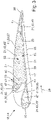
- the acoustic filler arrangement 21 has a hybrid form including three first type filler elements 43' with a non-porous, smooth outer surface 47 and one second type filler element 43" with a porous outer surface 51.
- the acoustic filler arrangement 21 is arranged in the inboard cavity 41 in such a way that the entire inboard cavity 41 is filled, i.e. all parts of the inboard cavity 41 are filled.
- the acoustic filler arrangement 21 is arranged in the inboard cavity 41 in such a way that the smooth outer surfaces 47 of the first type filler elements 43', in particular the lateral surfaces 53 facing out of the inboard cavity 41, extend in the same plane as the lateral edges 45 of the first and second skin portions 29, 31.
- the inboard cavity 41 is fully and continuously filled with the filler elements 43 which form a continuous and smooth common lateral surface 53 together with the lateral edges 45 in the area of the first type filler elements 43'.
- cut-outs 55 are provided in the first and second skin portions 29, 31 in the area of the second type filler element 43", which will be described in more detail further below.
- the first type filler element 43' is entirely formed of a non-porous, solid material, in the present embodiment aluminium, which has a hollow inside.
- the second type filler element 43" is entirely formed of a porous material in the form of an acoustic noise reduction foam, in the present embodiment a metal foam. Both first and second type filler elements 43', 43" are fixed in the inboard cavity 41 by bolts 60.
- the inboard cavity 41 is divided in multiple cavity sections 59 separated from one another by several cavity walls 61.
- Each cavity section 59 is filled with at least one first type filler element 43' or second type filler element 43".
- One cavity section 59 is filled with both one first type filler element 43' and one second type filler element 43".
- the inboard cavity 41 comprises two front cavity sections 65 in the area of the leading edge 27 which are arranged on opposite sides of a so-called fish mouth 63 of the flap 14, which refers to a guide rail for receiving a main wing based guide roller for guiding the aerodynamic surface 13 during extension or retraction movement.
- the inboard cavity 41 further comprises a rear cavity section 67 extending in the area of the trailing edge 28 and also in a central area 69.
- Each of the two front cavity sections 65 is filled with one first type filler element 43'.
- the rear cavity section 67 is filled with one first type filler element 43' arranged in the area of the trailing edge 28 and having a wedged shape, and one second type filler element 43" arranged upstream from the trailing edge 28 and the related first type filler element 43'.
- the second type filler element 43" is arranged in a central area 69 between at least two first type filler elements 43' arranged at the leading edge 27 and the trailing edge 28.
- cut-outs 55 are formed in the first and second skin portions 29, 31 in the area of the second type filler element 43", i.e. in area of the rear cavity section 67 in the central area 69 of the inboard cavity 41.
- the lateral edge 45 of the first skin portion 29 has a cut-out 55 in the area of the second type filler element 43", as shown in Fig. 4
- the lateral edge 45 of the second skin portion 31 has a cut-out 55 in the area of the second type filler element 43", as shown in Fig. 5 .
- the lateral edges 45 of the first and second skin portions 29, 31 do not extend in the same plane as the porous outer surface 51 of the second type filler element 43" and, thus, of the lateral surface 53, but instead are recessed in the span direction 20 relative to the porous outer surface 51 of the second type filler element 43", so that there are no sharp lateral edges 45 present in the area of the cut-out 55, but rather porous lateral edges of the second type filler element 43", which largely reduce vortices and thus broadband noise.
- the cut-outs have a depth, i.e. a span extension, of about 90% of the maximum profile thickness of the aerodynamic surface 13.
- the cut-outs 55 in the present embodiment do not extend along the entire chord extension of the second type filler element 43", so that there is a non-cut out area 71 at both chord ends of the second type filler element 43" for a better hold of the second type filler element 43".
- the cut-outs 55 in the present embodiment have edges extending in chord direction 26 and parallelly spaced from the lateral surface 53.
- the outboard end 25 of the aerodynamic surface 13 might be formed in the same way as the inboard end 23, including an outboard cavity (not shown) formed similar as the inboard cavity 41 and filled with an acoustic filler arrangement 21 as described above in connection with the inboard cavity 41.
- Such an aerodynamic surface 13 comprising a hybrid acoustic filler arrangement 21 combines the advantages of both first and second type filler elements 43', 43", i.e. of the smooth outer surface 47 and the porous outer surface 51.
- the parts of the inboard cavity 41 that are sufficiently large and simple shaped are filled with the second type filler elements 43" to achieve sufficient reduction of tonal and broadband noise, while the smaller and more complex shaped parts of the cavities 41 are filled with the first type filler elements 43' to allow cost-efficient production, installation and maintenance as well as convenient handling of the related filler elements 43. This allows that all noise due to resonance and most of the noise due to vortices can be widely reduced, while costs and effort are kept at a reasonable level.
Landscapes
- Engineering & Computer Science (AREA)
- Aviation & Aerospace Engineering (AREA)
- Mechanical Engineering (AREA)
- Physics & Mathematics (AREA)
- Acoustics & Sound (AREA)
- Multimedia (AREA)
- Soundproofing, Sound Blocking, And Sound Damping (AREA)
- Laminated Bodies (AREA)
Abstract
Description
- The present invention relates to a movable aerodynamic surface for an aircraft, configured for noise reduction, in particular a high lift surface, such as a flap or a slat, or a control surface, such as an aileron, a rudder or an elevator. Further aspects of the invention relate to a wing comprising such an aerodynamic surface, and to an aircraft comprising such an aerodynamic surface and/or such a wing.
- The aerodynamic surface comprises a skin, a stiffener arrangement, and an acoustic filler arrangement. The skin extends in a span direction from an inboard end to an outboard end and extends in a chord direction from a leading edge to a trailing edge. The skin includes a first skin portion, preferably an upper skin portion, and a second skin portion, preferably a lower skin portion. Both first and second skin portions extend from the leading edge to the trailing edge and together surround an interior of the aerodynamic surface from opposite sides.
- The stiffener arrangement arranged is in the interior for stiffening the first and second skin portions and includes at least an inboard stiffener in the area of the inboard end and/or an outboard stiffener in the area of the outboard end. Preferably, both the inboard stiffener and the outboard stiffener extend in the chord direction, preferably in a chord plane. At the inboard end between the first skin portion, the second skin portion and the inboard stiffener an inboard cavity is formed. Additionally or alternatively, at the outboard end between the first skin portion, the second skin portion and the outboard stiffener an outboard cavity is formed.
- The acoustic filler arrangement includes multiple filler elements and is arranged or received within the inboard cavity and/or within the outboard cavity for reducing noise generated at the inboard cavity and/or at the outboard cavity. The noise is usually generated by sharp lateral edges of the first and second skin portions upstream from the inboard and/or outboard cavity which cause vortices that in turn are responsible for an undesired broadband noise. Additionally, the noise is generated by resonance within the inboard and/or outboard cavity which acts as a Helmholtz resonator that may cause undesired tonal and broadband noise.
- Similar aerodynamic surfaces are known in the art, such as flaps, where various attempts have been made in the art to fill the cavities at the flap side edges in order to reduce unpleasant noise. In one attempt the cavities have been filled by solid filler elements with a smooth outer surface. Such filler elements were able to reduce resonance within the cavities and the resulting noise. However, partial broadband noise still remained as the sharp lateral edges of the first and second skin portions upstream the cavities were still present. Thus, in another attempt the cavities have been filled by foam filler elements with a porous outer surface. Such filler elements were able to reduce also the broadband noise by the sharp lateral edges being softened by the porous edges of the filler elements. However, the foam filler elements are difficult to produce, install and maintain at a small scale or complex shape, such as in the area of the leading edge or the trailing edge of the aerodynamic surface.
- Therefore, the object of the present invention is to provide an aerodynamic surface enabling both efficient noise reduction and convenient and cost-efficient handling.
- This object is achieved in that the acoustic filler arrangement has a hybrid form including at least one first type filler element with a smooth, non-porous outer surface and at least one second type filler element with a porous outer surface. In this connection the term "outer surface" relates to at least the lateral surface of the filler elements facing out of the inboard cavity and/or out of the outboard cavity, i.e. the surface transverse or perpendicular to the span direction and facing laterally away from the interior of the aerodynamic surface. The term "outer surface" might also relate to the entire outer surface of the first and/or second type filler elements. Such a hybrid acoustic filler arrangement combines the advantages of both types of filler elements, i.e. of the smooth outer surface and the porous outer surface. The parts of the cavities that are sufficiently large and simple shaped are filled with the second type filler elements to achieve sufficient reduction of tonal and broadband noise, while the smaller and more complex shaped parts of the cavities are filled with the first type filler elements to allow cost-efficient production, installation and maintenance as well as convenient handling of the related filler elements. This allows that all noise due to resonance and most of the noise due to vortices can be widely reduced, while costs and effort are kept at a reasonable level.
- According to a preferred embodiment, the acoustic filler arrangement includes one or more further first type filler elements and/or second type filler elements. In such a way, different parts of the cavities can be filled with different types of filler elements.
- According to a further preferred embodiment, the acoustic filler arrangement is arranged in the inboard cavity and/or in the outboard cavity in such a way that the entire inboard cavity and/or outboard cavity is filled, i.e. all parts of the inboard cavity and/or outboard cavity are filled. This leads to efficient reduction of the resonance noise.
- According to a further preferred embodiment, the acoustic filler arrangement is arranged in the inboard cavity and/or in the outboard cavity in such a way that the outer surfaces, in particular the lateral surfaces facing out of the inboard cavity and/or out of the outboard cavity, of the first and second type filler elements extend in the same plane, which is preferably the same plane in which at least some of the lateral edges of the first and second skin portions extend and which preferably extends transversely or perpendicularly to the span direction. In such a way, the inboard cavity and/or the outboard cavity is preferably fully and continuously filled with the filler elements which form a continuous and smooth common lateral surface, preferably together with the lateral edges. This further improves noise reduction.
- According to a further preferred embodiment, at the inboard end and/or at the outboard end, i.e. at the lateral edges, the first skin portion and/or the second skin portion has at least one cut-out, i.e. a recess, in the area of the second type filler element, preferably in a central area of the inboard and/or outboard cavity. I.e., the lateral edge of the first and/or second skin portion does not extend in the same plane as the porous outer surface of the second type filler element but instead is recessed or setback in the span direction relative to the porous outer surface of the second type filler element. In such a way, there are no sharp lateral edges present in the area of the cut-out, but rather porous lateral edges of the second type filler element, which largely reduce vortices and thus broadband noise. The cut-outs preferably have a depth, i.e. a span extension, of between 50% and 100%, preferably between 70% and 95%, most preferred about 90%, of the maximum profile thickness of the aerodynamic surface. The cut-outs might not extend along the entire chord extension of the second type filler element, so that there is a non-cut out area at both chord ends of the second type filler element for a better hold of the second type filler element. The cut-outs might have edges extending in chord direction and parallelly spaced from the lateral surface.
- According to a further preferred embodiment, the first type filler element is formed, preferably entirely formed, of a non-porous, solid material, which is preferably lightweight and resistant, such as plastic or metal, preferably aluminium, titanium or polymeric resin, which might or might not have a hollow inside. This relates to a very simple and efficient design. The first type filler element and/or the second type filler element can be fixed in the inboard cavity and/or in the outboard cavity by adhesive and/or by mechanical retainers, such as bolts.
- According to a further preferred embodiment, the second type filler element is formed, preferably entirely formed, of a porous material, preferably of a foam. This relates to a very simple and efficient design.
- In particular, it is preferred that the porous material is an acoustic noise reduction foam, such as a metal foam or a plastic foam. This material allows efficient noise reduction.
- According to a preferred embodiment, the inboard cavity and/or the outboard cavity is divided in multiple cavity sections separated from one another by one or more cavity walls. Such cavity walls are provided e.g. for stiffening or as a guide rail for receiving a guide roller, such as a so-called fish mouth of a flap.
- In particular, it is preferred that each cavity section is filled with at least one first type filler element and/or second type filler element. Thus, no cavity section remains unfilled which improved noise reduction.
- It is also preferred that at least one cavity is filled with both at least one first type filler element and at least one second type filler element. Thus, two different type filler elements are arranged in one common cavity section, which might be required, e.g., near edges or corners.
- According to a preferred embodiment, at least one, preferably two, first type filler elements are arranged in the cavity in the area of the leading edge. At least one second type filler element is arranged in the cavity in a central area. At least one first type filler element is arranged in the cavity in the area of the trailing edge. In such a way, the small and complex shapes at the leading edge and the trailing edge are filled with the more convenient first type filler elements, while the central area can be filled with the more complex porous second type filler element. This relates to a very simple design and effective noise reduction.
- It is preferred that the cavity comprises at least one front cavity section in the area of the leading edge and a rear cavity section in the area of the trailing edge and preferably also in a central area. Preferably, two front cavity sections are arranged in the area of the leading edge, preferably on opposite sides of a guide rail for receiving a guide roller, such as a so-called fish mouth of a flap. The at least one front cavity section, preferably each of the two front cavity sections, is filled with at least one first type filler element. The rear cavity section is filled with at least one first type filler element arranged in the area of the trailing edge and preferably having a wedge shape, and at least one second type filler element arranged upstream from the at least one first type filler element arranged in the area of the trailing edge. In such a way, the second type filler element is arranged between at least two first type filler elements arranged at the leading edge and the trailing edge. This relates to a very simple design and effective noise reduction.
- According to a preferred embodiment, the aerodynamic surface is formed as a high lift flap, i.e. a trailing edge flap, movably mounted to the trailing edge of a wing for an aircraft. Alternatively, the aerodynamic surface might be formed as another high lift surface, such as a slat, or as a control surface, such as an aileron, a rudder or an elevator. Reducing the noise originating from the flap side edges largely reduces the overall noise during take-off and approach of an aircraft.
- A further aspect of the invention relates to a wing for an aircraft comprising the aerodynamic surface according to any of the afore-described embodiments. Alternatively, the aerodynamic surface might be part of the vertical tail plane or the horizontal tail plane. The features and effects described above in connection with the aerodynamic surface apply vis-à-vis also to the wing.
- A further aspect of the invention relates to an aircraft comprising the aerodynamic surface according to any of the afore-described embodiments, and/or comprising the wing according to any of the afore-described embodiments. The features and effects described above in connection with the aerodynamic surface and the wing apply vis-à-vis also to the aircraft.
- Hereinafter, a preferred embodiment of the invention is described in more detail by means of a drawing. The drawing shows in
- Fig. 1
- a perspective view of an aircraft according to an embodiment of the invention,
- Fig. 2
- a perspective view of an aerodynamic surface in the form of a high lift flap of the aircraft shown in
Fig. 1 , with an unfilled cavity, - Fig. 3
- a cross sectional view of the high lift flap similar as the one shown in
Fig. 2 having a cavity filled with a hybrid acoustic filler arrangement according to the invention, - Fig. 4
- a perspective view from above of the high lift flap of
Fig. 3 showing the cut-out in the first skin portion, and - Fig. 5
- a perspective view from below of the high lift flap of
Fig. 3 showing the cut-out in the second skin portion. - In
Fig. 1 an aircraft 1 according to the invention is illustrated. The aircraft 1 has afuselage 3,wings 5, avertical tail plane 7 and ahorizontal tail plane 9. Eachwing 5 comprises amain wing 11 and at least one movable aerodynamic surface 13 in the form of a high lift flap 14 mounted to the trailing edge of themain wing 5 movably between a retracted position and an extended position. - As shown in
Fig. 2 , the aerodynamic surface 13 comprises askin 17, a stiffener arrangement 19, and an acoustic filler arrangement 21. Theskin 17 extends in aspan direction 20 from aninboard end 23 to anoutboard end 25 and extends in achord direction 26 from a leadingedge 27 to a trailingedge 28. Theskin 17 includes an upper,first skin portion 29 and a lower,second skin portion 31. Both first andsecond skin portions edge 27 to the trailingedge 28 and together surround an interior 33 of the aerodynamic surface 13 from opposite upper and lower sides. - The stiffener arrangement 19 arranged is in the interior 33 for stiffening the first and
second skin portions inboard end 23 and an outboard stiffener (not shown) in the area of theoutboard end 25. Both the inboard stiffener 39 and the outboard stiffener extend in thechord direction 26. However, only theinboard end 23 is shown in the Figures, so that the invention is described hereinafter only with reference to theinboard end 23, although theoutboard end 25 might be formed in the same way as theinboard end 23. At theinboard end 23 between thefirst skin portion 29, thesecond skin portion 31 and the inboard stiffener 39 an inboard cavity 41 is formed. - The acoustic filler arrangement 21 includes
multiple filler elements 43 and is arranged within the inboard cavity 41 for reducing noise generated at the inboard cavity 41. The noise is usually generated by sharplateral edges 45 of the first andsecond skin portions - As shown in
Fig. 3 , the acoustic filler arrangement 21 has a hybrid form including three first type filler elements 43' with a non-porous, smoothouter surface 47 and one secondtype filler element 43" with a porousouter surface 51. - The acoustic filler arrangement 21 is arranged in the inboard cavity 41 in such a way that the entire inboard cavity 41 is filled, i.e. all parts of the inboard cavity 41 are filled. The acoustic filler arrangement 21 is arranged in the inboard cavity 41 in such a way that the smooth
outer surfaces 47 of the first type filler elements 43', in particular the lateral surfaces 53 facing out of the inboard cavity 41, extend in the same plane as the lateral edges 45 of the first andsecond skin portions filler elements 43 which form a continuous and smooth commonlateral surface 53 together with the lateral edges 45 in the area of the first type filler elements 43'. However, cut-outs 55 are provided in the first andsecond skin portions type filler element 43", which will be described in more detail further below. - The first type filler element 43' is entirely formed of a non-porous, solid material, in the present embodiment aluminium, which has a hollow inside. The second
type filler element 43" is entirely formed of a porous material in the form of an acoustic noise reduction foam, in the present embodiment a metal foam. Both first and secondtype filler elements 43', 43" are fixed in the inboard cavity 41 bybolts 60. - The inboard cavity 41 is divided in multiple cavity sections 59 separated from one another by
several cavity walls 61. Each cavity section 59 is filled with at least one first type filler element 43' or secondtype filler element 43". One cavity section 59 is filled with both one first type filler element 43' and one secondtype filler element 43". - As shown in
Fig. 3 , the inboard cavity 41 comprises two front cavity sections 65 in the area of the leadingedge 27 which are arranged on opposite sides of a so-calledfish mouth 63 of the flap 14, which refers to a guide rail for receiving a main wing based guide roller for guiding the aerodynamic surface 13 during extension or retraction movement. The inboard cavity 41 further comprises a rear cavity section 67 extending in the area of the trailingedge 28 and also in acentral area 69. Each of the two front cavity sections 65 is filled with one first type filler element 43'. The rear cavity section 67 is filled with one first type filler element 43' arranged in the area of the trailingedge 28 and having a wedged shape, and one secondtype filler element 43" arranged upstream from the trailingedge 28 and the related first type filler element 43'. In such a way, the secondtype filler element 43" is arranged in acentral area 69 between at least two first type filler elements 43' arranged at theleading edge 27 and the trailingedge 28. - As shown in
Figs. 4 and 5 , cut-outs 55 are formed in the first andsecond skin portions type filler element 43", i.e. in area of the rear cavity section 67 in thecentral area 69 of the inboard cavity 41. Specifically, thelateral edge 45 of thefirst skin portion 29 has a cut-out 55 in the area of the secondtype filler element 43", as shown inFig. 4 , and thelateral edge 45 of thesecond skin portion 31 has a cut-out 55 in the area of the secondtype filler element 43", as shown inFig. 5 . This means, the lateral edges 45 of the first andsecond skin portions outer surface 51 of the secondtype filler element 43" and, thus, of thelateral surface 53, but instead are recessed in thespan direction 20 relative to the porousouter surface 51 of the secondtype filler element 43", so that there are no sharplateral edges 45 present in the area of the cut-out 55, but rather porous lateral edges of the secondtype filler element 43", which largely reduce vortices and thus broadband noise. The cut-outs have a depth, i.e. a span extension, of about 90% of the maximum profile thickness of the aerodynamic surface 13. The cut-outs 55 in the present embodiment do not extend along the entire chord extension of the secondtype filler element 43", so that there is a non-cut outarea 71 at both chord ends of the secondtype filler element 43" for a better hold of the secondtype filler element 43". The cut-outs 55 in the present embodiment have edges extending inchord direction 26 and parallelly spaced from thelateral surface 53. - Although not shown in the Figures, the
outboard end 25 of the aerodynamic surface 13 might be formed in the same way as theinboard end 23, including an outboard cavity (not shown) formed similar as the inboard cavity 41 and filled with an acoustic filler arrangement 21 as described above in connection with the inboard cavity 41. - Such an aerodynamic surface 13 comprising a hybrid acoustic filler arrangement 21 combines the advantages of both first and second
type filler elements 43', 43", i.e. of the smoothouter surface 47 and the porousouter surface 51. The parts of the inboard cavity 41 that are sufficiently large and simple shaped are filled with the secondtype filler elements 43" to achieve sufficient reduction of tonal and broadband noise, while the smaller and more complex shaped parts of the cavities 41 are filled with the first type filler elements 43' to allow cost-efficient production, installation and maintenance as well as convenient handling of the relatedfiller elements 43. This allows that all noise due to resonance and most of the noise due to vortices can be widely reduced, while costs and effort are kept at a reasonable level.
Claims (15)
- A movable aerodynamic surface (13) for an aircraft (1), comprisinga skin (17) extending in a span direction (20) from an inboard end (23) to an outboard end (25) and extending in a chord direction (26) from a leading edge (27) to a trailing edge (28), wherein the skin (17) includes a first skin portion (29) and a second skin portion (31) both extending from the leading edge (27) to the trailing edge (28) and together surrounding an interior (33) from opposite sides, anda stiffener arrangement (19) arranged in the interior (33) for stiffening the first and second skin portions (29, 31) and including at least an inboard stiffener (41) in the area of the inboard end (23) and/or an outboard stiffener in the area of the outboard end (25),wherein at the inboard end (23) between the first skin portion (29), the second skin portion (31) and the inboard stiffener (39) an inboard cavity (41) is formed, and/or at the outboard end (25) between the first skin portion (29), the second skin portion (31) and the outboard stiffener an outboard cavity is formed,wherein an acoustic filler arrangement (21) including multiple filler elements (21) is arranged within the inboard cavity (41) and/or the outboard cavity for reducing noise generated at the inboard cavity (41) and/or at the outboard cavity,characterized in thatthe acoustic filler arrangement (21) has a hybrid form including at least one first type filler element (43') with a smooth outer surface (47) and at least one second type filler element (43") with a porous outer surface (51).
- The aerodynamic surface (13) according to claim 1, wherein the acoustic filler arrangement (21) includes one or more further first type filler elements (43') and/or second type filler elements (43").
- The aerodynamic surface (13) according to claim 1 or 2, wherein the acoustic filler arrangement (21) is arranged in the inboard cavity (41) and/or in the outboard cavity in such a way that the entire inboard cavity (41) and/or outboard cavity is filled.
- The aerodynamic surface (13) according to any of claims 1 to 3, wherein the acoustic filler arrangement (21) is arranged in the inboard cavity (41) and/or in the outboard cavity in such a way that the outer surfaces (47, 51) of the filler elements (43) extend in the same plane as at least some of the lateral edges (45) of the first and second skin portions (29, 31).
- The aerodynamic surface (13) according to any of claims 1 to 4, wherein at the inboard end (23) and/or at the outboard end (25) the first skin portion (29) and/or the second skin portion (31) has at least one cut-out (55) in the area of the second type filler element (43").
- The aerodynamic surface (13) according to any of claims 1 to 5, wherein the first type filler element (43') is formed of a non-porous, solid material, such as plastic or metal.
- The aerodynamic surface (13) according to any of claims 1 to 6, wherein the second filler element (43") is formed of a porous material, which is preferably an acoustic noise reduction foam.
- The aerodynamic surface (13) according to any of claims 1 to 7, wherein the inboard cavity (41) and/or the outboard cavity is divided in multiple cavity sections (59) separated from one another by one or more cavity walls (61).
- The aerodynamic surface (13) according to claim 8, wherein each cavity section (59) is filled with at least one first type filler element (43') and/or second type filler element, (43").
- The aerodynamic surface (13) according to claim 8 or 9, wherein at least one cavity section (59) is filled with both at least one first type filler element (43') and at least one second type filler element, (43").
- The aerodynamic surface (13) according to any of claims 1 to 10, wherein at least one first type filler element (43') is arranged in the inboard cavity (41) and/or in the outboard cavity in the area of the leading edge (27),wherein at least one second type filler element (43") is arranged in the inboard cavity (41) and/or in the outboard cavity in a central area (69), andwherein at least one first type filler element (43') is arranged in the inboard cavity (41) and/or in the outboard cavity in the area of the trailing edge (28).
- The aerodynamic surface (13) according to any of claims 8 to 11, wherein the inboard cavity (41) and/or the outboard cavity comprises at least one front cavity section (65) in the area of the leading edge (27) and a rear cavity section (67) in the area of the trailing edge (28),wherein the at least one front cavity section (71) is filled with at least one first type filler element (43'),wherein the rear cavity section (67) is filled with at least one first type filler element (43') arranged in the area of the trailing edge (28) and at least one second type filler element (43") arranged upstream from the at least one first type filler element (43').
- The aerodynamic surface (13) according to any of claims 1 to 12, wherein the aerodynamic surface (13) is formed as a high lift flap.
- A wing (5) for an aircraft (1) comprising the aerodynamic surface (13) according to any of claims 1 to 13.
- An aircraft (1) comprising the aerodynamic surface (13) according to any of claims 1 to 13, and/or comprising the wing (5) according to claim 14.
Applications Claiming Priority (1)
| Application Number | Priority Date | Filing Date | Title |
|---|---|---|---|
| DE102021107280 | 2021-03-23 |
Publications (2)
| Publication Number | Publication Date |
|---|---|
| EP4063260A1 true EP4063260A1 (en) | 2022-09-28 |
| EP4063260B1 EP4063260B1 (en) | 2025-01-29 |
Family
ID=80930234
Family Applications (1)
| Application Number | Title | Priority Date | Filing Date |
|---|---|---|---|
| EP22163395.1A Active EP4063260B1 (en) | 2021-03-23 | 2022-03-21 | Movable aerodynamic surface for an aircraft |
Country Status (3)
| Country | Link |
|---|---|
| US (1) | US12162584B2 (en) |
| EP (1) | EP4063260B1 (en) |
| CN (1) | CN115107991A (en) |
Citations (4)
| Publication number | Priority date | Publication date | Assignee | Title |
|---|---|---|---|---|
| US9199721B2 (en) * | 2013-01-29 | 2015-12-01 | Gulfstream Aerospace Corporation | Wing flaps for aircraft and methods for making the same |
| DE102016123096A1 (en) * | 2016-11-30 | 2018-05-30 | Airbus Defence and Space GmbH | Control surface component for a buoyancy aid of an aircraft and manufacturing method thereof |
| US20200070951A1 (en) * | 2018-09-03 | 2020-03-05 | Airbus Defence and Space GmbH | Noise reduced end rib assembly for a high-lift device of an aircraft |
| US20200298953A1 (en) * | 2017-10-11 | 2020-09-24 | Fokker Aerostructures Bv | Noise attenuation panel |
Family Cites Families (4)
| Publication number | Priority date | Publication date | Assignee | Title |
|---|---|---|---|---|
| BRPI0916330A2 (en) | 2008-07-30 | 2018-06-12 | Aircelle Sa | acoustic attenuation panel for an aircraft engine nacelle, air intake structure, internal fixed structure |
| US9227719B2 (en) * | 2011-03-11 | 2016-01-05 | The United States Of America As Represented By The Administrator Of The National Aeronautics And Space Administration | Reactive orthotropic lattice diffuser for noise reduction |
| FR2976556B1 (en) | 2011-06-17 | 2013-12-27 | Airbus Operations Sas | AIR INTAKE OF AN AIRCRAFT NACELLE INCORPORATING A REINFORCED LIP WITH A JELLY EFFECT DEFROSTING SYSTEM |
| EP3233626B1 (en) | 2014-12-18 | 2019-09-25 | Bombardier Inc. | Sound absorbers for airframe components |
-
2022
- 2022-03-21 EP EP22163395.1A patent/EP4063260B1/en active Active
- 2022-03-22 CN CN202210283219.1A patent/CN115107991A/en active Pending
- 2022-03-22 US US17/701,192 patent/US12162584B2/en active Active
Patent Citations (4)
| Publication number | Priority date | Publication date | Assignee | Title |
|---|---|---|---|---|
| US9199721B2 (en) * | 2013-01-29 | 2015-12-01 | Gulfstream Aerospace Corporation | Wing flaps for aircraft and methods for making the same |
| DE102016123096A1 (en) * | 2016-11-30 | 2018-05-30 | Airbus Defence and Space GmbH | Control surface component for a buoyancy aid of an aircraft and manufacturing method thereof |
| US20200298953A1 (en) * | 2017-10-11 | 2020-09-24 | Fokker Aerostructures Bv | Noise attenuation panel |
| US20200070951A1 (en) * | 2018-09-03 | 2020-03-05 | Airbus Defence and Space GmbH | Noise reduced end rib assembly for a high-lift device of an aircraft |
Also Published As
| Publication number | Publication date |
|---|---|
| EP4063260B1 (en) | 2025-01-29 |
| US12162584B2 (en) | 2024-12-10 |
| CN115107991A (en) | 2022-09-27 |
| US20220306273A1 (en) | 2022-09-29 |
Similar Documents
| Publication | Publication Date | Title |
|---|---|---|
| US6491260B2 (en) | Noise reducing vortex generators on aircraft wing control surfaces | |
| CA2937135C (en) | High-lift device of flight vehicle | |
| EP1843942B1 (en) | Aerospace vehicle leading edge slat devices and corresponding methods | |
| BR112017002081B1 (en) | CONTROL SURFACE ELEMENT FOR AN AIRCRAFT | |
| US20150329197A1 (en) | Flow Body With A Load Introduction Element Integrated Therein, Method For Manufacturing A Flow Body, And Aircraft With Such A Flow Body | |
| US20080001036A1 (en) | Aerospace vehicle fairing systems and associated methods | |
| US9533750B2 (en) | Slat, wing of aircraft, flight control surface of aircraft, and aircraft | |
| US20130026295A1 (en) | Flow body with a base body and a leading edge | |
| US20180155006A1 (en) | Aircraft stabilizer leading edge integration with torsion box and fuselage | |
| CN116101479A (en) | Structural component for an aircraft and aircraft having such a structural component | |
| EP4063260B1 (en) | Movable aerodynamic surface for an aircraft | |
| EP2641830B1 (en) | Seal assembly for an aircraft wing | |
| US9440729B2 (en) | High-lift-device, wing, and noise reduction device for high-lift-device | |
| US20180148163A1 (en) | Control surface component for a high-lift device of an aircraft and production method therefor | |
| RU189694U1 (en) | Gondola body | |
| US6869050B1 (en) | Profiled wing unit of an aircraft | |
| EP4438466B1 (en) | Sealing strip, control surface arrangement, aircraft wing and aircraft | |
| US11919618B2 (en) | Aircraft pressurized cabin door with a structure formed by beams having a varying cross-section | |
| US10023295B2 (en) | Aircraft including a fuselage sponson | |
| US12371148B2 (en) | Aerodynamic system for an aircraft | |
| EP4438465A1 (en) | Sealing strip, control surface arrangement, aircraft wing and aircraft | |
| RU2222477C1 (en) | Amphibian aeroplane | |
| JPH05286498A (en) | aircraft | |
| CN117755476A (en) | Aircraft wing and method of operating an aircraft wing |
Legal Events
| Date | Code | Title | Description |
|---|---|---|---|
| PUAI | Public reference made under article 153(3) epc to a published international application that has entered the european phase |
Free format text: ORIGINAL CODE: 0009012 |
|
| STAA | Information on the status of an ep patent application or granted ep patent |
Free format text: STATUS: THE APPLICATION HAS BEEN PUBLISHED |
|
| AK | Designated contracting states |
Kind code of ref document: A1 Designated state(s): AL AT BE BG CH CY CZ DE DK EE ES FI FR GB GR HR HU IE IS IT LI LT LU LV MC MK MT NL NO PL PT RO RS SE SI SK SM TR |
|
| STAA | Information on the status of an ep patent application or granted ep patent |
Free format text: STATUS: REQUEST FOR EXAMINATION WAS MADE |
|
| 17P | Request for examination filed |
Effective date: 20230328 |
|
| RBV | Designated contracting states (corrected) |
Designated state(s): AL AT BE BG CH CY CZ DE DK EE ES FI FR GB GR HR HU IE IS IT LI LT LU LV MC MK MT NL NO PL PT RO RS SE SI SK SM TR |
|
| GRAP | Despatch of communication of intention to grant a patent |
Free format text: ORIGINAL CODE: EPIDOSNIGR1 |
|
| STAA | Information on the status of an ep patent application or granted ep patent |
Free format text: STATUS: GRANT OF PATENT IS INTENDED |
|
| RIC1 | Information provided on ipc code assigned before grant |
Ipc: B64C 9/18 20060101ALI20240807BHEP Ipc: B64C 9/00 20060101ALI20240807BHEP Ipc: B64C 7/00 20060101AFI20240807BHEP |
|
| INTG | Intention to grant announced |
Effective date: 20240905 |
|
| GRAS | Grant fee paid |
Free format text: ORIGINAL CODE: EPIDOSNIGR3 |
|
| GRAA | (expected) grant |
Free format text: ORIGINAL CODE: 0009210 |
|
| STAA | Information on the status of an ep patent application or granted ep patent |
Free format text: STATUS: THE PATENT HAS BEEN GRANTED |
|
| AK | Designated contracting states |
Kind code of ref document: B1 Designated state(s): AL AT BE BG CH CY CZ DE DK EE ES FI FR GB GR HR HU IE IS IT LI LT LU LV MC MK MT NL NO PL PT RO RS SE SI SK SM TR |
|
| REG | Reference to a national code |
Ref country code: GB Ref legal event code: FG4D |
|
| REG | Reference to a national code |
Ref country code: CH Ref legal event code: EP |
|
| REG | Reference to a national code |
Ref country code: DE Ref legal event code: R096 Ref document number: 602022009931 Country of ref document: DE |
|
| REG | Reference to a national code |
Ref country code: IE Ref legal event code: FG4D |
|
| PGFP | Annual fee paid to national office [announced via postgrant information from national office to epo] |
Ref country code: AT Payment date: 20250417 Year of fee payment: 4 |
|
| REG | Reference to a national code |
Ref country code: NL Ref legal event code: MP Effective date: 20250129 |
|
| PG25 | Lapsed in a contracting state [announced via postgrant information from national office to epo] |
Ref country code: NL Free format text: LAPSE BECAUSE OF FAILURE TO SUBMIT A TRANSLATION OF THE DESCRIPTION OR TO PAY THE FEE WITHIN THE PRESCRIBED TIME-LIMIT Effective date: 20250129 |
|
| PG25 | Lapsed in a contracting state [announced via postgrant information from national office to epo] |
Ref country code: RS Free format text: LAPSE BECAUSE OF FAILURE TO SUBMIT A TRANSLATION OF THE DESCRIPTION OR TO PAY THE FEE WITHIN THE PRESCRIBED TIME-LIMIT Effective date: 20250429 |
|
| PG25 | Lapsed in a contracting state [announced via postgrant information from national office to epo] |
Ref country code: FI Free format text: LAPSE BECAUSE OF FAILURE TO SUBMIT A TRANSLATION OF THE DESCRIPTION OR TO PAY THE FEE WITHIN THE PRESCRIBED TIME-LIMIT Effective date: 20250129 |
|
| PG25 | Lapsed in a contracting state [announced via postgrant information from national office to epo] |
Ref country code: PL Free format text: LAPSE BECAUSE OF FAILURE TO SUBMIT A TRANSLATION OF THE DESCRIPTION OR TO PAY THE FEE WITHIN THE PRESCRIBED TIME-LIMIT Effective date: 20250129 |
|
| PG25 | Lapsed in a contracting state [announced via postgrant information from national office to epo] |
Ref country code: ES Free format text: LAPSE BECAUSE OF FAILURE TO SUBMIT A TRANSLATION OF THE DESCRIPTION OR TO PAY THE FEE WITHIN THE PRESCRIBED TIME-LIMIT Effective date: 20250129 |
|
| REG | Reference to a national code |
Ref country code: LT Ref legal event code: MG9D |
|
| PG25 | Lapsed in a contracting state [announced via postgrant information from national office to epo] |
Ref country code: NO Free format text: LAPSE BECAUSE OF FAILURE TO SUBMIT A TRANSLATION OF THE DESCRIPTION OR TO PAY THE FEE WITHIN THE PRESCRIBED TIME-LIMIT Effective date: 20250429 Ref country code: IS Free format text: LAPSE BECAUSE OF FAILURE TO SUBMIT A TRANSLATION OF THE DESCRIPTION OR TO PAY THE FEE WITHIN THE PRESCRIBED TIME-LIMIT Effective date: 20250529 |
|
| REG | Reference to a national code |
Ref country code: AT Ref legal event code: MK05 Ref document number: 1763224 Country of ref document: AT Kind code of ref document: T Effective date: 20250129 |
|
| PG25 | Lapsed in a contracting state [announced via postgrant information from national office to epo] |
Ref country code: HR Free format text: LAPSE BECAUSE OF FAILURE TO SUBMIT A TRANSLATION OF THE DESCRIPTION OR TO PAY THE FEE WITHIN THE PRESCRIBED TIME-LIMIT Effective date: 20250129 |
|
| PG25 | Lapsed in a contracting state [announced via postgrant information from national office to epo] |
Ref country code: PT Free format text: LAPSE BECAUSE OF FAILURE TO SUBMIT A TRANSLATION OF THE DESCRIPTION OR TO PAY THE FEE WITHIN THE PRESCRIBED TIME-LIMIT Effective date: 20250529 Ref country code: LV Free format text: LAPSE BECAUSE OF FAILURE TO SUBMIT A TRANSLATION OF THE DESCRIPTION OR TO PAY THE FEE WITHIN THE PRESCRIBED TIME-LIMIT Effective date: 20250129 |
|
| PG25 | Lapsed in a contracting state [announced via postgrant information from national office to epo] |
Ref country code: BG Free format text: LAPSE BECAUSE OF FAILURE TO SUBMIT A TRANSLATION OF THE DESCRIPTION OR TO PAY THE FEE WITHIN THE PRESCRIBED TIME-LIMIT Effective date: 20250129 Ref country code: GR Free format text: LAPSE BECAUSE OF FAILURE TO SUBMIT A TRANSLATION OF THE DESCRIPTION OR TO PAY THE FEE WITHIN THE PRESCRIBED TIME-LIMIT Effective date: 20250430 |
|
| PG25 | Lapsed in a contracting state [announced via postgrant information from national office to epo] |
Ref country code: AT Free format text: LAPSE BECAUSE OF FAILURE TO SUBMIT A TRANSLATION OF THE DESCRIPTION OR TO PAY THE FEE WITHIN THE PRESCRIBED TIME-LIMIT Effective date: 20250129 |
|
| PG25 | Lapsed in a contracting state [announced via postgrant information from national office to epo] |
Ref country code: SE Free format text: LAPSE BECAUSE OF FAILURE TO SUBMIT A TRANSLATION OF THE DESCRIPTION OR TO PAY THE FEE WITHIN THE PRESCRIBED TIME-LIMIT Effective date: 20250129 |
|
| PG25 | Lapsed in a contracting state [announced via postgrant information from national office to epo] |
Ref country code: SM Free format text: LAPSE BECAUSE OF FAILURE TO SUBMIT A TRANSLATION OF THE DESCRIPTION OR TO PAY THE FEE WITHIN THE PRESCRIBED TIME-LIMIT Effective date: 20250129 |
|
| PG25 | Lapsed in a contracting state [announced via postgrant information from national office to epo] |
Ref country code: DK Free format text: LAPSE BECAUSE OF FAILURE TO SUBMIT A TRANSLATION OF THE DESCRIPTION OR TO PAY THE FEE WITHIN THE PRESCRIBED TIME-LIMIT Effective date: 20250129 |
|
| PG25 | Lapsed in a contracting state [announced via postgrant information from national office to epo] |
Ref country code: MC Free format text: LAPSE BECAUSE OF FAILURE TO SUBMIT A TRANSLATION OF THE DESCRIPTION OR TO PAY THE FEE WITHIN THE PRESCRIBED TIME-LIMIT Effective date: 20250129 |
|
| PG25 | Lapsed in a contracting state [announced via postgrant information from national office to epo] |
Ref country code: IT Free format text: LAPSE BECAUSE OF FAILURE TO SUBMIT A TRANSLATION OF THE DESCRIPTION OR TO PAY THE FEE WITHIN THE PRESCRIBED TIME-LIMIT Effective date: 20250129 |
|
| PG25 | Lapsed in a contracting state [announced via postgrant information from national office to epo] |
Ref country code: EE Free format text: LAPSE BECAUSE OF FAILURE TO SUBMIT A TRANSLATION OF THE DESCRIPTION OR TO PAY THE FEE WITHIN THE PRESCRIBED TIME-LIMIT Effective date: 20250129 Ref country code: CZ Free format text: LAPSE BECAUSE OF FAILURE TO SUBMIT A TRANSLATION OF THE DESCRIPTION OR TO PAY THE FEE WITHIN THE PRESCRIBED TIME-LIMIT Effective date: 20250129 |
|
| REG | Reference to a national code |
Ref country code: CH Ref legal event code: H13 Free format text: ST27 STATUS EVENT CODE: U-0-0-H10-H13 (AS PROVIDED BY THE NATIONAL OFFICE) Effective date: 20251023 |
|
| PG25 | Lapsed in a contracting state [announced via postgrant information from national office to epo] |
Ref country code: RO Free format text: LAPSE BECAUSE OF FAILURE TO SUBMIT A TRANSLATION OF THE DESCRIPTION OR TO PAY THE FEE WITHIN THE PRESCRIBED TIME-LIMIT Effective date: 20250129 |
|
| PG25 | Lapsed in a contracting state [announced via postgrant information from national office to epo] |
Ref country code: SK Free format text: LAPSE BECAUSE OF FAILURE TO SUBMIT A TRANSLATION OF THE DESCRIPTION OR TO PAY THE FEE WITHIN THE PRESCRIBED TIME-LIMIT Effective date: 20250129 |
|
| REG | Reference to a national code |
Ref country code: DE Ref legal event code: R097 Ref document number: 602022009931 Country of ref document: DE |
|
| PG25 | Lapsed in a contracting state [announced via postgrant information from national office to epo] |
Ref country code: LU Free format text: LAPSE BECAUSE OF NON-PAYMENT OF DUE FEES Effective date: 20250321 |
|
| PLBE | No opposition filed within time limit |
Free format text: ORIGINAL CODE: 0009261 |
|
| STAA | Information on the status of an ep patent application or granted ep patent |
Free format text: STATUS: NO OPPOSITION FILED WITHIN TIME LIMIT |
|
| 26N | No opposition filed |
Effective date: 20251030 |
|
| PG25 | Lapsed in a contracting state [announced via postgrant information from national office to epo] |
Ref country code: CH Free format text: LAPSE BECAUSE OF NON-PAYMENT OF DUE FEES Effective date: 20250331 |
|
| PG25 | Lapsed in a contracting state [announced via postgrant information from national office to epo] |
Ref country code: IE Free format text: LAPSE BECAUSE OF NON-PAYMENT OF DUE FEES Effective date: 20250321 |
|
| PGFP | Annual fee paid to national office [announced via postgrant information from national office to epo] |
Ref country code: GB Payment date: 20260324 Year of fee payment: 5 |
|
| PGFP | Annual fee paid to national office [announced via postgrant information from national office to epo] |
Ref country code: DE Payment date: 20260319 Year of fee payment: 5 |
|
| PGFP | Annual fee paid to national office [announced via postgrant information from national office to epo] |
Ref country code: BE Payment date: 20260319 Year of fee payment: 5 |
|
| PGFP | Annual fee paid to national office [announced via postgrant information from national office to epo] |
Ref country code: FR Payment date: 20260323 Year of fee payment: 5 |