EP4063258A2 - Wing for an aircraft - Google Patents
Wing for an aircraft Download PDFInfo
- Publication number
- EP4063258A2 EP4063258A2 EP22161877.0A EP22161877A EP4063258A2 EP 4063258 A2 EP4063258 A2 EP 4063258A2 EP 22161877 A EP22161877 A EP 22161877A EP 4063258 A2 EP4063258 A2 EP 4063258A2
- Authority
- EP
- European Patent Office
- Prior art keywords
- high lift
- wing
- lift body
- main wing
- link
- Prior art date
- Legal status (The legal status is an assumption and is not a legal conclusion. Google has not performed a legal analysis and makes no representation as to the accuracy of the status listed.)
- Pending
Links
- 230000000712 assembly Effects 0.000 description 4
- 238000000429 assembly Methods 0.000 description 4
- 238000005452 bending Methods 0.000 description 4
- 230000000694 effects Effects 0.000 description 3
- 230000001154 acute effect Effects 0.000 description 1
- 238000006073 displacement reaction Methods 0.000 description 1
Images



Classifications
-
- B—PERFORMING OPERATIONS; TRANSPORTING
- B64—AIRCRAFT; AVIATION; COSMONAUTICS
- B64C—AEROPLANES; HELICOPTERS
- B64C3/00—Wings
- B64C3/38—Adjustment of complete wings or parts thereof
- B64C3/44—Varying camber
- B64C3/50—Varying camber by leading or trailing edge flaps
-
- B—PERFORMING OPERATIONS; TRANSPORTING
- B64—AIRCRAFT; AVIATION; COSMONAUTICS
- B64C—AEROPLANES; HELICOPTERS
- B64C13/00—Control systems or transmitting systems for actuating flying-control surfaces, lift-increasing flaps, air brakes, or spoilers
- B64C13/24—Transmitting means
- B64C13/26—Transmitting means without power amplification or where power amplification is irrelevant
- B64C13/28—Transmitting means without power amplification or where power amplification is irrelevant mechanical
- B64C13/30—Transmitting means without power amplification or where power amplification is irrelevant mechanical using cable, chain, or rod mechanisms
-
- B—PERFORMING OPERATIONS; TRANSPORTING
- B64—AIRCRAFT; AVIATION; COSMONAUTICS
- B64C—AEROPLANES; HELICOPTERS
- B64C3/00—Wings
- B64C3/26—Construction, shape, or attachment of separate skins, e.g. panels
-
- B—PERFORMING OPERATIONS; TRANSPORTING
- B64—AIRCRAFT; AVIATION; COSMONAUTICS
- B64C—AEROPLANES; HELICOPTERS
- B64C3/00—Wings
- B64C3/28—Leading or trailing edges attached to primary structures, e.g. forming fixed slots
-
- B—PERFORMING OPERATIONS; TRANSPORTING
- B64—AIRCRAFT; AVIATION; COSMONAUTICS
- B64C—AEROPLANES; HELICOPTERS
- B64C3/00—Wings
- B64C3/38—Adjustment of complete wings or parts thereof
- B64C3/44—Varying camber
- B64C3/48—Varying camber by relatively-movable parts of wing structures
-
- B—PERFORMING OPERATIONS; TRANSPORTING
- B64—AIRCRAFT; AVIATION; COSMONAUTICS
- B64C—AEROPLANES; HELICOPTERS
- B64C9/00—Adjustable control surfaces or members, e.g. rudders
- B64C9/02—Mounting or supporting thereof
-
- B—PERFORMING OPERATIONS; TRANSPORTING
- B64—AIRCRAFT; AVIATION; COSMONAUTICS
- B64C—AEROPLANES; HELICOPTERS
- B64C9/00—Adjustable control surfaces or members, e.g. rudders
- B64C9/04—Adjustable control surfaces or members, e.g. rudders with compound dependent movements
-
- B—PERFORMING OPERATIONS; TRANSPORTING
- B64—AIRCRAFT; AVIATION; COSMONAUTICS
- B64C—AEROPLANES; HELICOPTERS
- B64C9/00—Adjustable control surfaces or members, e.g. rudders
- B64C9/14—Adjustable control surfaces or members, e.g. rudders forming slots
- B64C9/22—Adjustable control surfaces or members, e.g. rudders forming slots at the front of the wing
-
- B—PERFORMING OPERATIONS; TRANSPORTING
- B64—AIRCRAFT; AVIATION; COSMONAUTICS
- B64C—AEROPLANES; HELICOPTERS
- B64C9/00—Adjustable control surfaces or members, e.g. rudders
- B64C9/14—Adjustable control surfaces or members, e.g. rudders forming slots
- B64C9/22—Adjustable control surfaces or members, e.g. rudders forming slots at the front of the wing
- B64C9/24—Adjustable control surfaces or members, e.g. rudders forming slots at the front of the wing by single flap
Definitions
- the present invention relates to a wing for an aircraft. Further aspects of the invention relate to a leading edge high lift assembly for such a wing as well as a an aircraft comprising such a leading edge high lift assembly and/or such a wing.
- the wing comprises a main wing and a leading edge high lift assembly movable relative to the main wing to increase lift of the wing.
- the leading edge high lift assembly comprises a high lift body and a connection assembly.
- the high lift body is preferably a droop high lift body referred to as droop nose, droop leading edge, droop flap or slat, in particular sealed slat.
- the connection assembly is configured for connecting the high lift body to the main wing, in particular to the leading edge of the main wing, in such a way that the high lift body is movable relative to the main wing between a stowed position and a deployed position.
- the stowed position relates to a position where the wing profile has a lower curvature and might also be referred to as straight position, normal position, cruise position or retracted position, while the deployed position relates to a position where the wing profile has a higher curvature and might also be referred to as drooped position, landing position, on-ground position or extended position.
- the connection assembly comprises at least one rotation element, such as a rotation rod or a part of the high lift body structure, that is mounted to the high lift body and that is mounted to the main wing rotatably about an axis of rotation.
- the rotation element is mounted to the high lift body directly or indirectly and in a fixed or rotatable manner, preferably in a fixed, non-rotatable manner, e.g. by being bolted to a rib of the high lift body or by a hinge between the end of the rotation element and the high lift body and additionally by a fixing link that is hinged to the rotation element and that is hinged to the high lift body spaced apart from the rotation element, so that a relative rotation of the high lift body and the rotation element is prevented.
- the axis of rotation preferably extends in parallel to the span direction and/or in parallel to the extension of leading edge along the wing, so that the high lift body is preferably rotated about the axis of rotation when moved between the stowed position and the deployed position.
- the main wing comprises an upper skin panel for contact with an ambient flow on an upper side of the main wing, and a lower skin panel for contact with the ambient flow on a lower side of the main wing.
- the upper skin panel has a leading edge portion in the area of a leading edge of the main wing and facing the high lift body.
- the upper skin panel and the lower skin panel might be joined at the leading edge of the main wing, or might have an open end at the leading edge of the main wing, where they might be connected or supported against each other via a front spar.
- the high lift body comprises a rigid portion and a flexible skin portion configured for contact with the ambient flow.
- the rigid portion is mounted, preferably fixedly mounted, to the rotation element.
- the flexible skin portion is connected, preferably fixedly and directly connected, in particular directly attached or integrally formed, to the leading edge portion of the upper skin panel and is connected, preferably fixedly and directly connected, in particular directly attached or integrally formed, to the rigid portion of the high lift body, preferably in the area of a leading edge of the high lift body.
- the flexible skin portion is configured to be deformed, preferably elastically deformed, between a stowed deformation state and a deployed deformation state, when the high lift body is moved between the stowed position and the deployed position, so that the flexible skin portion is in the stowed deformation state when the high lift body is in the stowed position and the flexible skin portion is in the deployed deformation state when the high lift body is in the deployed position.
- Similar wings are known in the art. By increasing the curvature of the wing profile when the high lift body is moved to the deployed position, lift of the related aircraft can be increased, in particular to allow approach and landing with lower speed and on shorter runways.
- High lift assemblies with a drooping, downward rotating high lift body that is sealed to the leading edge portion of the upper skin panel, such as droop nose assemblies, relate to simple and effective high lift devices.
- form-stability of the high lift body and specifically of the flexible skin portion is important, in particular during cruise of an associated aircraft when high air loads act on the high lift body.
- the object of the present invention is to provide a simple and lightweight wing with a form-stable high lift body.
- the flexible skin portion in the stowed deformation state is pre-stressed so that it comprises a predefined stress, in particular internal stress.
- a predefined stress in particular internal stress.
- the form-stability of the flexible skin portion increases drastically even under the high air loads during cruise.
- the thickness of the flexible skin portion can be reduced and the flexible skin portion does not need to be supported between the rigid portion of the high lift body and the leading edge portion of the upper skin panel of the main wing, thereby reducing weight and complexity of the wing.
- the flexible skin portion in the stowed deformation state is pre-stressed in a chord direction so that it comprises a predefined tensile stress in the chord direction.
- the tensile stress results in a good form-stability of the flexible skin portion.
- the flexible skin portion might also be pre-stressed by bending about the span direction so that it comprises a predefined bending stress in the stowed deformation state.
- the flexible skin portion might also be pre-stressed by bending in the stowed deformation state in such a way that the flexible skin portion is relaxed, i.e. the bending stress is removed, when it is in the deployed deformation state.
- the flexible skin portion in the deployed deformation state is relaxed, i.e. in a relaxed state, so that the predefined stress is removed.
- form-stability is achieved by the higher curvature of the flexible skin portion compared to the stowed deformation state.
- the high lift body is usually in the deployed position during take-off and landing when the air loads are considerably lower as during cruise.
- the predefined stress is only partly removed from the flexible skin portion in the deployed position, so that a residual stress remains.
- the axis of rotation of the rotation element extends outside an outer mold line of the wing, i.e. outside a cross section across the span direction of the wing, preferably above the flexible skin portion, preferably near the attachment of the flexible skin portion at the upper skin panel of the main wing.
- Such a position of the axis of rotation can be achieved by a respective design or configuration of the connection assembly. By such a position of the axis of rotation it can be avoided that the flexible skin portion is stretched when the high lift body is moved into the deployed position.
- the features of this embodiment, i.e. the axis of rotation of the rotation element extending outside an outer mold line of the wing also forms an independent aspect of the present invention independent from the features relating to the flexible skin portion being pre-stressed in the stowed deformation state.
- the leading edge high lift assembly comprises a pre-stressing device for introducing and preferably also removing the predefined stress into the flexible skin portion.
- the pre-stressing device can have different forms but preferably includes a mechanism mounted between the main wing and the rotation element or the rigid portion of the high lift body. In such a way, the predefined stress can be easily and reliably introduced into the flexible skin portion.
- the pre-stressing device comprises a linkage that is rotatably mounted to the rotation element and that is rotatably mounted to the main wing.
- the linkage is movable between an extended state and a retracted state.
- the linkage is in the extended state when the flexible skin portion is in the stowed deformation state, and the linkage is in the retracted state when the flexible skin portion is in the deployed deformation state. In such a way, the flexible skin portion can be pre-stressed by bringing the linkage into the extended state.
- the linkage comprises a first link rotatably and preferably directly mounted to the rotation element, preferably by its one end, and a second link rotatably mounted to the other end of the first link by its one end and rotatably mounted to the main wing, preferably by its other end.
- the first link and the second link in the extended state of the linkage the first link and the second link enclose a larger angle, while in the retracted state of the linkage the first link and the second link enclose a smaller, i.e. more acute, angle.
- the axes of rotation of the first and second links extend in parallel to the span direction and/or to the axis of rotation about which the rotation element rotates relative to the main wing. In such a way, a very efficient linkage is provided for introducing the predefined stress.
- the first link is mounted to the second link by a rotatable joint.
- the pre-stressing device further comprises a guide element mounted to the main wing, preferably in the form of a guide roller mounted to the main wing rotatably about a fixed rotation axis, preferably parallel to the span direction and/or to the axes of rotation of the first and second links.
- the guide element guides the rotatable joint when the linkage is moved from the retracted state to the extended state of the linkage and preferably supports the rotatably joint in the extended state in a predetermined position.
- the first link slides along the guide element, when the linkage is moved from the retracted state to the extended state, until the rotatable joint meets the guide element, and thereby straightens and extends the linkage.
- a very efficient pre-stressing device is formed.
- the second link is mounted to the main wing via a third link that is rotatably and preferably directly mounted to the main wing, preferably by one end, and that is rotatably mounted to the second link, preferably by its other end.
- the axis of rotation about which the third link is mounted rotatably to the fixed wing is fixed relative to the main wing and/or extends in parallel to the span direction and/or to the axes of rotation of the first and second links.
- the third link might not have an elongate form but might have the form of e.g. a plate. This relates to a very efficient linkage.
- the third link comprises a linear guide, such as a linear displacement bearing, a sliding bearing or a sliding restraint.
- the rotation element comprises or is formed as a rod that is guided in a linearly displaceable manner by the linear guide, preferably received within the linear guide in a linearly displaceable manner, so that the rod can be linearly moved along or within the linear guide when the linkage is moved between the retracted state and the extended state.
- movement of the linkage between the retracted state and the extended state causes a linear movement of the rod along or within the linear guide.
- the direction of linear movement of the rod along or within the linear guide is perpendicular to the axis about which the third link rotates.
- the third link and linear guide allow the rotation element to linearly move which is results in the introduction or removal of the predefined stress.
- the pre-stressing device comprises a pre-stress adjuster for adjusting, in particular calibrating, the amount of predefined stress introduced into the flexible skin portion by the pre-stressing device in the stowed deformation state. This allows the pre-stressing device to be calibrated by the pre-stress adjuster.
- the pre-stress adjuster is formed by the first link being length-adjustable, preferably by a length-adjustment screw, such as a tensioning screw, bottle screw, or turnbuckle, preferably being in threaded engagement with the two opposite ends of the first link and being rotatable about the longitudinal axis of the first link for length adjustment.
- a length-adjustment screw such as a tensioning screw, bottle screw, or turnbuckle
- the leading edge high lift assembly comprises an actuator for moving the high lift body between the stowed position and the deployed position.
- the actuator might be a geared rotary actuator that is driven by a rotating drive shaft extending along the span of the wing.
- the actuator directly or indirectly causes the linkage to move between the retracted state and the extended state and thus causes the pre-stressing device to introduce or remove the predefined stress.
- the actuator is mounted, preferably fixedly mounted, to the main wing, preferably to a chordwise mounting rib connected to a front spar of the main wing.
- the actuator has a rotatable drive arm driving the high lift body preferably via a drive link that is rotatably mounted to the drive arm, preferably by its one end, and that is rotatably mounted to the rigid portion of the high lift body, preferably by its other end. In such a way, a simple, reliable and efficient actuator is formed.
- the leading edge high lift assembly comprises a further connection assembly spaced from the connection assembly in the span direction and preferably formed as the connection assembly.
- Preferably at least two spaced connection assemblies are provided to carry each high lift body.
- Each connection assembly might also comprise more than one rotation element. In such a way, a stable hold and movement of the high lift body is achieved.
- a further aspect of the present invention relates to a wing for an aircraft.
- the wing comprises a main wing and a leading edge high lift assembly.
- the leading edge high lift assembly comprises a high lift body and a connection assembly connecting the high lift body to the main wing in such a way that the high lift body is movable relative to the main wing between a stowed position and a deployed position.
- the connection assembly comprises at least one rotation element that is mounted to the high lift body and that is mounted to the main wing rotatably about an axis of rotation.
- the main wing comprises an upper skin panel and a lower skin panel, wherein the upper skin panel has a leading edge portion.
- the high lift body comprises a rigid portion and a flexible skin portion. The rigid portion is mounted to the rotation element.
- the flexible skin portion is connected to the leading edge portion of the upper skin panel and is connected to the rigid portion of the high lift body.
- the flexible skin portion is configured to be deformed between a stowed deformation state and a deployed deformation state, when the high lift body is moved between the stowed position and the deployed position.
- the axis of rotation of the rotation element extends outside an outer mold line of the wing.
- a further aspect of the invention relates to a leading edge high lift assembly for the wing according to any of the afore-described embodiments and aspects.
- the leading edge high lift assembly comprises a high lift body and a connection assembly for connecting the high lift body to a main wing in such a way that the high lift body is movable relative to the main wing between a stowed position and a deployed position.
- the connection assembly comprises a rotation element that is mounted to the high lift body and that is configured to be mounted to the main wing rotatably about an axis of rotation.
- the high lift body comprises a rigid portion and a flexible skin portion. The rigid portion is mounted to the rotation element.
- the flexible skin portion is configured to be connected to a leading edge portion of an upper skin panel of the main wing and is connected to the rigid portion of the high lift body.
- the flexible skin portion is configured to be deformed between a stowed deformation state and a deployed deformation state, when the high lift body is moved between the stowed position and the deployed position.
- the flexible skin portion In the stowed deformation state the flexible skin portion is configured to be pre-stressed so that it comprises a predefined stress.
- the leading edge high lift assembly is configured such that the axis of rotation of the rotation element extends outside an outer mold line of the wing, when the wing is in the assembled state.
- a further aspect of the invention relates to an aircraft comprising the wing according to any of the afore-described embodiments and/or comprising the leading edge high lift assembly according to any of the afore described embodiments.
- the wing according to any of the afore-described embodiments and/or comprising the leading edge high lift assembly according to any of the afore described embodiments.
- FIG. 1 an embodiment of an aircraft 1 according to the present invention is illustrated.
- the aircraft 1 comprises a fuselage 3, wings 5, a vertical tail plane 7 and a horizontal tail plane 9.
- Figs. 2 to 9 show in more detail several embodiments of the wings 5.
- Figs. 2 and 3 show an embodiment of the wing 5 according to the invention.
- the wing 5 comprises a main wing 11 and a leading edge high lift assembly 13 movable relative to the main wing 11 to increase lift of the wing 5.
- the leading edge high lift assembly 13 comprises a high lift body 15 and a connection assembly 17.
- the high lift body 15 is a droop high lift body also referred to as droop nose, droop leading edge, droop flap or slat, in particular sealed slat.
- the connection assembly 17 is configured for connecting the high lift body 15 to the leading edge of the main wing 11 in such a way that the high lift body 15 is movable relative to the main wing 11 between a stowed position and a deployed position.
- the stowed position relates to a position where the wing profile has a lower curvature
- the deployed position relates to a position where the wing profile has a higher curvature.
- the connection assembly 17 comprises at least one rotation element 19 that is mounted to the high lift body 15 and that is mounted to the main wing 11 rotatably about an axis of rotation 21.
- the rotation element 19 is mounted to the high lift body 15 in a fixed, non-rotatable manner by being bolted to a rigid rib 28 of the high lift body 15.
- the axis of rotation 21 extends in parallel to a span direction 29 and in parallel to the extension of leading edge along the wing 5, so that the high lift body 15 is rotated about the axis of rotation 21 when moved between the stowed position and the deployed position.
- the axis of rotation 21 of the rotation element 19 extends outside an outer mold line of the wing 5 above the high lift body 15.
- the main wing 11 comprises an upper skin panel 31 for contact with an ambient flow 34 on an upper side of the main wing 11, and a lower skin panel 33 for contact with the ambient flow 34 on a lower side of the main wing 11.
- the upper skin panel 31 has a leading edge portion 35 in the area of a leading edge of the main wing 11 and facing the high lift body 15.
- the upper skin panel 31 and the lower skin panel 33 are connected and supported against each other via a front spar 39.
- the high lift body 15 comprises a rigid portion 30 and a flexible skin portion 32 configured for contact with the ambient flow 34.
- the rigid portion 30 is fixedly mounted to the rotation element 19.
- the flexible skin portion 32 is fixedly and directly attached to the leading edge portion 35 of the upper skin panel 31 and is fixedly and directly attached to the rigid portion 30 of the high lift body 15 in the area of a leading edge 41 of the high lift body 15.
- the flexible skin portion 32 is configured to be elastically deformed between a stowed deformation state and a deployed deformation state, when the high lift body 15 is moved between the stowed position and the deployed position, so that the flexible skin portion 32 is in the stowed deformation state when the high lift body 15 is in the stowed position and the flexible skin portion 32 is in the deployed deformation state when the high lift body 15 is in the deployed position.
- the flexible skin portion 32 In the stowed deformation state the flexible skin portion 32 is pre-stressed in a chord direction 67 so that it comprises a predefined stress in the form of tensile stress. In the deployed deformation state the flexible skin portion 32 is relaxed so that the predefined stress is removed.
- the leading edge high lift assembly 13 comprises a pre-stressing device 43 for introducing and removing the predefined stress into the flexible skin portion 32.
- the pre-stressing device 43 comprises a linkage 45 that is rotatably mounted to the rotation element 19 and that is rotatably mounted to the main wing 11.
- the linkage 45 is movable between an extended state and a retracted state. The linkage 45 is in the extended state when the flexible skin portion 32 is in the stowed deformation state, and the linkage 45 is in the retracted state when the flexible skin portion 32 is in the deployed deformation state.
- the linkage 45 comprises a first link 47 rotatably and directly mounted to the rotation element 19 and a second link 49 rotatably and directly mounted to the first link 47 and rotatably mounted to the main wing 11.
- first link 47 and the second link 49 enclose a larger angle
- first link 47 and the second link 49 enclose a smaller angle.
- the first link 47 is mounted to the second link 49 by a rotatable joint 51.
- the pre-stressing device 43 further comprises a guide element 53 in the form of a guide roller mounted to the main wing 11 directly and rotatably about a fixed rotation axis 55.
- the guide element 53 guides the rotatable joint 51 when the linkage 45 is moved from the retracted state to the extended state of the linkage 45 and supports the rotatable joint 51 in the extended state in a predetermined position.
- the first link 47 slides along the guide element 53, when the linkage 45 is moved from the retracted state to the extended state, until the rotatable joint 51 meets the guide element 53, and thereby straightens and extends the linkage 45.
- the second link 49 is mounted to the main wing 11 via a third link 59 that is rotatably and directly mounted to the main wing 11 and that is rotatably and directly mounted to the second link 49.
- the axis of rotation 60 about which the third link 59 is mounted rotatably to the main wing is fixed relative to the main wing.
- the third link 59 comprises a linear guide 61.
- the rotation element 19 comprises a rod 63 that is received and guided in a linearly displaceable manner within the linear guide 61, so that the rod 63 can be linearly moved within the linear guide 61 when the linkage 45 is moved between the retracted state and the extended state.
- the direction of linear movement of the rod 63 within the linear guide 61 is perpendicular to the axis about which the third link 59 rotates.
- the pre-stressing device 43 comprises a pre-stress adjuster 69 for adjusting and calibrating the amount of predefined stress introduced into the flexible skin portion 32 by the pre-stressing device 69 in the stowed deformation state.
- the pre-stress adjuster 69 is formed by the first link 47 being length-adjustable by a length-adjustment screw 71 being in threaded engagement with the two opposite ends of the first link 47 and being rotatable about the longitudinal axis of the first link 47 for length adjustment.
- the leading edge high lift assembly 13 further comprises an actuator 75 for moving the high lift body 15 between the stowed position and the deployed position, as shown in Figs. 2, 3 , 6 and 7 .
- the actuator 75 is fixedly mounted to a chordwise mounting rib 77 connected to the front spar 39 of the main wing 11, as shown in Figs. 6 and 7 .
- the actuator 75 has a rotatable drive arm 79 driving the high lift body 15 via a drive link 81 that is rotatably mounted to the drive arm 79 and that is rotatably mounted to the rigid portion 30 of the high lift body 15.
- the leading edge high lift assembly 13 comprises a further connection assembly 17' spaced from the connection assembly 17 in the span direction 29 and preferably formed as the connection assembly 17. At least two spaced connection assemblies 17, 17' are provided to carry each high lift body 15. Each connection assembly 17, 17' might also comprise more than one rotation element 19.
- a wing 5 with a very efficient leading edge high lift assembly 13 can be formed.
- the form-stability of the flexible skin portion 32 increases drastically even under the high air loads during cruise.
- the thickness of the flexible skin portion 32 can be reduced and the flexible skin portion 32 does not need to be supported between the rigid portion 30 of the high lift body 15 and the leading edge portion 35 of the upper skin panel 31 of the main wing 11, thereby reducing weight and complexity of the wing 5.
Landscapes
- Engineering & Computer Science (AREA)
- Aviation & Aerospace Engineering (AREA)
- Mechanical Engineering (AREA)
- Automation & Control Theory (AREA)
- Toys (AREA)
- Structures Of Non-Positive Displacement Pumps (AREA)
- Turbine Rotor Nozzle Sealing (AREA)
Abstract
Description
- The present invention relates to a wing for an aircraft. Further aspects of the invention relate to a leading edge high lift assembly for such a wing as well as a an aircraft comprising such a leading edge high lift assembly and/or such a wing.
- The wing comprises a main wing and a leading edge high lift assembly movable relative to the main wing to increase lift of the wing. The leading edge high lift assembly comprises a high lift body and a connection assembly. The high lift body is preferably a droop high lift body referred to as droop nose, droop leading edge, droop flap or slat, in particular sealed slat. The connection assembly is configured for connecting the high lift body to the main wing, in particular to the leading edge of the main wing, in such a way that the high lift body is movable relative to the main wing between a stowed position and a deployed position. The stowed position relates to a position where the wing profile has a lower curvature and might also be referred to as straight position, normal position, cruise position or retracted position, while the deployed position relates to a position where the wing profile has a higher curvature and might also be referred to as drooped position, landing position, on-ground position or extended position.
- The connection assembly comprises at least one rotation element, such as a rotation rod or a part of the high lift body structure, that is mounted to the high lift body and that is mounted to the main wing rotatably about an axis of rotation. The rotation element is mounted to the high lift body directly or indirectly and in a fixed or rotatable manner, preferably in a fixed, non-rotatable manner, e.g. by being bolted to a rib of the high lift body or by a hinge between the end of the rotation element and the high lift body and additionally by a fixing link that is hinged to the rotation element and that is hinged to the high lift body spaced apart from the rotation element, so that a relative rotation of the high lift body and the rotation element is prevented. The axis of rotation preferably extends in parallel to the span direction and/or in parallel to the extension of leading edge along the wing, so that the high lift body is preferably rotated about the axis of rotation when moved between the stowed position and the deployed position.
- The main wing comprises an upper skin panel for contact with an ambient flow on an upper side of the main wing, and a lower skin panel for contact with the ambient flow on a lower side of the main wing. The upper skin panel has a leading edge portion in the area of a leading edge of the main wing and facing the high lift body. The upper skin panel and the lower skin panel might be joined at the leading edge of the main wing, or might have an open end at the leading edge of the main wing, where they might be connected or supported against each other via a front spar.
- The high lift body comprises a rigid portion and a flexible skin portion configured for contact with the ambient flow. The rigid portion is mounted, preferably fixedly mounted, to the rotation element. The flexible skin portion is connected, preferably fixedly and directly connected, in particular directly attached or integrally formed, to the leading edge portion of the upper skin panel and is connected, preferably fixedly and directly connected, in particular directly attached or integrally formed, to the rigid portion of the high lift body, preferably in the area of a leading edge of the high lift body. The flexible skin portion is configured to be deformed, preferably elastically deformed, between a stowed deformation state and a deployed deformation state, when the high lift body is moved between the stowed position and the deployed position, so that the flexible skin portion is in the stowed deformation state when the high lift body is in the stowed position and the flexible skin portion is in the deployed deformation state when the high lift body is in the deployed position.
- Similar wings are known in the art. By increasing the curvature of the wing profile when the high lift body is moved to the deployed position, lift of the related aircraft can be increased, in particular to allow approach and landing with lower speed and on shorter runways. High lift assemblies with a drooping, downward rotating high lift body that is sealed to the leading edge portion of the upper skin panel, such as droop nose assemblies, relate to simple and effective high lift devices. However, form-stability of the high lift body and specifically of the flexible skin portion is important, in particular during cruise of an associated aircraft when high air loads act on the high lift body. To achieve form-stability it is known to increase the thickness of the flexible skin portion or to support the flexible skin portion from the inside e.g. by a number of links. This, however, increases weight and complexity of the leading edge high lift assembly.
- Therefore, the object of the present invention is to provide a simple and lightweight wing with a form-stable high lift body.
- This object is achieved in that in the stowed deformation state the flexible skin portion is pre-stressed so that it comprises a predefined stress, in particular internal stress. By pre-stressing the flexible skin portion in the stowed deformation state the form-stability of the flexible skin portion increases drastically even under the high air loads during cruise. At the same time, the thickness of the flexible skin portion can be reduced and the flexible skin portion does not need to be supported between the rigid portion of the high lift body and the leading edge portion of the upper skin panel of the main wing, thereby reducing weight and complexity of the wing.
- According to a preferred embodiment, in the stowed deformation state the flexible skin portion is pre-stressed in a chord direction so that it comprises a predefined tensile stress in the chord direction. The tensile stress results in a good form-stability of the flexible skin portion. Alternatively, the flexible skin portion might also be pre-stressed by bending about the span direction so that it comprises a predefined bending stress in the stowed deformation state. In particular, the flexible skin portion might also be pre-stressed by bending in the stowed deformation state in such a way that the flexible skin portion is relaxed, i.e. the bending stress is removed, when it is in the deployed deformation state.
- According to a further preferred embodiment, in the deployed deformation state the flexible skin portion is relaxed, i.e. in a relaxed state, so that the predefined stress is removed. In the deployed deformation state form-stability is achieved by the higher curvature of the flexible skin portion compared to the stowed deformation state. Further, the high lift body is usually in the deployed position during take-off and landing when the air loads are considerably lower as during cruise. However, it is also possible that the predefined stress is only partly removed from the flexible skin portion in the deployed position, so that a residual stress remains.
- According to a further preferred embodiment, the axis of rotation of the rotation element extends outside an outer mold line of the wing, i.e. outside a cross section across the span direction of the wing, preferably above the flexible skin portion, preferably near the attachment of the flexible skin portion at the upper skin panel of the main wing. Such a position of the axis of rotation can be achieved by a respective design or configuration of the connection assembly. By such a position of the axis of rotation it can be avoided that the flexible skin portion is stretched when the high lift body is moved into the deployed position. The features of this embodiment, i.e. the axis of rotation of the rotation element extending outside an outer mold line of the wing, also forms an independent aspect of the present invention independent from the features relating to the flexible skin portion being pre-stressed in the stowed deformation state.
- According to a further preferred embodiment, the leading edge high lift assembly comprises a pre-stressing device for introducing and preferably also removing the predefined stress into the flexible skin portion. The pre-stressing device can have different forms but preferably includes a mechanism mounted between the main wing and the rotation element or the rigid portion of the high lift body. In such a way, the predefined stress can be easily and reliably introduced into the flexible skin portion.
- In particular, it is preferred that the pre-stressing device comprises a linkage that is rotatably mounted to the rotation element and that is rotatably mounted to the main wing. By such a linkage the predefined stress can be easily and reliably introduced into the flexible skin portion.
- It is further preferred that the linkage is movable between an extended state and a retracted state. Preferably, the linkage is in the extended state when the flexible skin portion is in the stowed deformation state, and the linkage is in the retracted state when the flexible skin portion is in the deployed deformation state. In such a way, the flexible skin portion can be pre-stressed by bringing the linkage into the extended state.
- It is also preferred that the linkage comprises a first link rotatably and preferably directly mounted to the rotation element, preferably by its one end, and a second link rotatably mounted to the other end of the first link by its one end and rotatably mounted to the main wing, preferably by its other end. Preferably, in the extended state of the linkage the first link and the second link enclose a larger angle, while in the retracted state of the linkage the first link and the second link enclose a smaller, i.e. more acute, angle. Preferably, the axes of rotation of the first and second links extend in parallel to the span direction and/or to the axis of rotation about which the rotation element rotates relative to the main wing. In such a way, a very efficient linkage is provided for introducing the predefined stress.
- In particular, it is preferred that the first link is mounted to the second link by a rotatable joint. The pre-stressing device further comprises a guide element mounted to the main wing, preferably in the form of a guide roller mounted to the main wing rotatably about a fixed rotation axis, preferably parallel to the span direction and/or to the axes of rotation of the first and second links. The guide element guides the rotatable joint when the linkage is moved from the retracted state to the extended state of the linkage and preferably supports the rotatably joint in the extended state in a predetermined position. Preferably, the first link slides along the guide element, when the linkage is moved from the retracted state to the extended state, until the rotatable joint meets the guide element, and thereby straightens and extends the linkage. In such a way, a very efficient pre-stressing device is formed.
- Further, it is preferred that the second link is mounted to the main wing via a third link that is rotatably and preferably directly mounted to the main wing, preferably by one end, and that is rotatably mounted to the second link, preferably by its other end. Preferably, the axis of rotation about which the third link is mounted rotatably to the fixed wing is fixed relative to the main wing and/or extends in parallel to the span direction and/or to the axes of rotation of the first and second links. The third link might not have an elongate form but might have the form of e.g. a plate. This relates to a very efficient linkage.
- In particular, it is preferred that the third link comprises a linear guide, such as a linear displacement bearing, a sliding bearing or a sliding restraint. The rotation element comprises or is formed as a rod that is guided in a linearly displaceable manner by the linear guide, preferably received within the linear guide in a linearly displaceable manner, so that the rod can be linearly moved along or within the linear guide when the linkage is moved between the retracted state and the extended state. In particular, movement of the linkage between the retracted state and the extended state causes a linear movement of the rod along or within the linear guide. Preferably, the direction of linear movement of the rod along or within the linear guide is perpendicular to the axis about which the third link rotates. The third link and linear guide allow the rotation element to linearly move which is results in the introduction or removal of the predefined stress.
- According to a preferred embodiment, the pre-stressing device comprises a pre-stress adjuster for adjusting, in particular calibrating, the amount of predefined stress introduced into the flexible skin portion by the pre-stressing device in the stowed deformation state. This allows the pre-stressing device to be calibrated by the pre-stress adjuster.
- In particular, it is preferred that the pre-stress adjuster is formed by the first link being length-adjustable, preferably by a length-adjustment screw, such as a tensioning screw, bottle screw, or turnbuckle, preferably being in threaded engagement with the two opposite ends of the first link and being rotatable about the longitudinal axis of the first link for length adjustment. By adjusting the length of the first link the predefined stress in the flexible skin portion can be adjusted in a simple and efficient manner.
- According to a further preferred embodiment, the leading edge high lift assembly comprises an actuator for moving the high lift body between the stowed position and the deployed position. The actuator might be a geared rotary actuator that is driven by a rotating drive shaft extending along the span of the wing. The actuator directly or indirectly causes the linkage to move between the retracted state and the extended state and thus causes the pre-stressing device to introduce or remove the predefined stress.
- In particular, it is preferred that the actuator is mounted, preferably fixedly mounted, to the main wing, preferably to a chordwise mounting rib connected to a front spar of the main wing. Preferably, the actuator has a rotatable drive arm driving the high lift body preferably via a drive link that is rotatably mounted to the drive arm, preferably by its one end, and that is rotatably mounted to the rigid portion of the high lift body, preferably by its other end. In such a way, a simple, reliable and efficient actuator is formed.
- According to a further preferred embodiment, the leading edge high lift assembly comprises a further connection assembly spaced from the connection assembly in the span direction and preferably formed as the connection assembly. Preferably at least two spaced connection assemblies are provided to carry each high lift body. Each connection assembly might also comprise more than one rotation element. In such a way, a stable hold and movement of the high lift body is achieved.
- A further aspect of the present invention relates to a wing for an aircraft. The wing comprises a main wing and a leading edge high lift assembly. The leading edge high lift assembly comprises a high lift body and a connection assembly connecting the high lift body to the main wing in such a way that the high lift body is movable relative to the main wing between a stowed position and a deployed position. The connection assembly comprises at least one rotation element that is mounted to the high lift body and that is mounted to the main wing rotatably about an axis of rotation. The main wing comprises an upper skin panel and a lower skin panel, wherein the upper skin panel has a leading edge portion. The high lift body comprises a rigid portion and a flexible skin portion. The rigid portion is mounted to the rotation element. The flexible skin portion is connected to the leading edge portion of the upper skin panel and is connected to the rigid portion of the high lift body. The flexible skin portion is configured to be deformed between a stowed deformation state and a deployed deformation state, when the high lift body is moved between the stowed position and the deployed position. The axis of rotation of the rotation element extends outside an outer mold line of the wing. The features, embodiments and effects described above in connection with the wing according to the first aspect apply vis-a-vis also to the wing according to present second aspect of the invention.
- A further aspect of the invention relates to a leading edge high lift assembly for the wing according to any of the afore-described embodiments and aspects. The leading edge high lift assembly comprises a high lift body and a connection assembly for connecting the high lift body to a main wing in such a way that the high lift body is movable relative to the main wing between a stowed position and a deployed position. The connection assembly comprises a rotation element that is mounted to the high lift body and that is configured to be mounted to the main wing rotatably about an axis of rotation. The high lift body comprises a rigid portion and a flexible skin portion. The rigid portion is mounted to the rotation element. The flexible skin portion is configured to be connected to a leading edge portion of an upper skin panel of the main wing and is connected to the rigid portion of the high lift body. The flexible skin portion is configured to be deformed between a stowed deformation state and a deployed deformation state, when the high lift body is moved between the stowed position and the deployed position. In the stowed deformation state the flexible skin portion is configured to be pre-stressed so that it comprises a predefined stress. Alternatively, the leading edge high lift assembly is configured such that the axis of rotation of the rotation element extends outside an outer mold line of the wing, when the wing is in the assembled state. Features and effects described above in connection with the wing apply vis-a-vis also to the leading edge high lift assembly.
- A further aspect of the invention relates to an aircraft comprising the wing according to any of the afore-described embodiments and/or comprising the leading edge high lift assembly according to any of the afore described embodiments. Features and effects described above in connection with the wing and in connection with the leading edge high lift assembly apply vis-a-vis also to the aircraft.
- A preferred embodiment of the present invention is explained hereinafter in more detail by means of a drawing. The drawing shows in
- Fig. 1
- a perspective view of an aircraft according to the invention,
- Fig. 2
- a cross-sectional view across the span direction of a wing according to the invention with a high lift body in the stowed position,
- Fig. 3
- the wing shown in
Fig. 2 with the high lift body in the deployed position, - Fig. 4
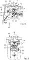
- a detailed view of the pre-stressing device of the wing shown in
Fig. 2 , - Fig. 5
- a sectional view along section A-A in
Fig. 4 , - Fig. 6
- the wing of
Fig. 2 showing details of the mounting of the actuator to the front spar, and - Fig. 7
- a sectional view along section A-A in
Fig. 6 . - In
Fig. 1 an embodiment of anaircraft 1 according to the present invention is illustrated. Theaircraft 1 comprises afuselage 3,wings 5, avertical tail plane 7 and ahorizontal tail plane 9.Figs. 2 to 9 show in more detail several embodiments of thewings 5. -
Figs. 2 and 3 show an embodiment of thewing 5 according to the invention. Thewing 5 comprises amain wing 11 and a leading edgehigh lift assembly 13 movable relative to themain wing 11 to increase lift of thewing 5. The leading edgehigh lift assembly 13 comprises ahigh lift body 15 and aconnection assembly 17. Thehigh lift body 15 is a droop high lift body also referred to as droop nose, droop leading edge, droop flap or slat, in particular sealed slat. Theconnection assembly 17 is configured for connecting thehigh lift body 15 to the leading edge of themain wing 11 in such a way that thehigh lift body 15 is movable relative to themain wing 11 between a stowed position and a deployed position. The stowed position relates to a position where the wing profile has a lower curvature, while the deployed position relates to a position where the wing profile has a higher curvature. - The
connection assembly 17 comprises at least one rotation element 19 that is mounted to thehigh lift body 15 and that is mounted to themain wing 11 rotatably about an axis ofrotation 21. The rotation element 19 is mounted to thehigh lift body 15 in a fixed, non-rotatable manner by being bolted to arigid rib 28 of thehigh lift body 15. The axis ofrotation 21 extends in parallel to aspan direction 29 and in parallel to the extension of leading edge along thewing 5, so that thehigh lift body 15 is rotated about the axis ofrotation 21 when moved between the stowed position and the deployed position. The axis ofrotation 21 of the rotation element 19 extends outside an outer mold line of thewing 5 above thehigh lift body 15. - The
main wing 11 comprises anupper skin panel 31 for contact with anambient flow 34 on an upper side of themain wing 11, and alower skin panel 33 for contact with theambient flow 34 on a lower side of themain wing 11. Theupper skin panel 31 has aleading edge portion 35 in the area of a leading edge of themain wing 11 and facing thehigh lift body 15. Theupper skin panel 31 and thelower skin panel 33 are connected and supported against each other via afront spar 39. - The
high lift body 15 comprises arigid portion 30 and aflexible skin portion 32 configured for contact with theambient flow 34. Therigid portion 30 is fixedly mounted to the rotation element 19. Theflexible skin portion 32 is fixedly and directly attached to theleading edge portion 35 of theupper skin panel 31 and is fixedly and directly attached to therigid portion 30 of thehigh lift body 15 in the area of aleading edge 41 of thehigh lift body 15. Theflexible skin portion 32 is configured to be elastically deformed between a stowed deformation state and a deployed deformation state, when thehigh lift body 15 is moved between the stowed position and the deployed position, so that theflexible skin portion 32 is in the stowed deformation state when thehigh lift body 15 is in the stowed position and theflexible skin portion 32 is in the deployed deformation state when thehigh lift body 15 is in the deployed position. - In the stowed deformation state the
flexible skin portion 32 is pre-stressed in achord direction 67 so that it comprises a predefined stress in the form of tensile stress. In the deployed deformation state theflexible skin portion 32 is relaxed so that the predefined stress is removed. - As shown in more detail in
Figs. 4 and 5 , the leading edgehigh lift assembly 13 comprises apre-stressing device 43 for introducing and removing the predefined stress into theflexible skin portion 32. Thepre-stressing device 43 comprises alinkage 45 that is rotatably mounted to the rotation element 19 and that is rotatably mounted to themain wing 11. Thelinkage 45 is movable between an extended state and a retracted state. Thelinkage 45 is in the extended state when theflexible skin portion 32 is in the stowed deformation state, and thelinkage 45 is in the retracted state when theflexible skin portion 32 is in the deployed deformation state. - The
linkage 45 comprises afirst link 47 rotatably and directly mounted to the rotation element 19 and asecond link 49 rotatably and directly mounted to thefirst link 47 and rotatably mounted to themain wing 11. In the extended state of thelinkage 45 thefirst link 47 and thesecond link 49 enclose a larger angle, while in the retracted state of thelinkage 45 thefirst link 47 and thesecond link 49 enclose a smaller angle. - The
first link 47 is mounted to thesecond link 49 by a rotatable joint 51. Thepre-stressing device 43 further comprises aguide element 53 in the form of a guide roller mounted to themain wing 11 directly and rotatably about afixed rotation axis 55. Theguide element 53 guides the rotatable joint 51 when thelinkage 45 is moved from the retracted state to the extended state of thelinkage 45 and supports the rotatable joint 51 in the extended state in a predetermined position. Thefirst link 47 slides along theguide element 53, when thelinkage 45 is moved from the retracted state to the extended state, until the rotatable joint 51 meets theguide element 53, and thereby straightens and extends thelinkage 45. - The
second link 49 is mounted to themain wing 11 via athird link 59 that is rotatably and directly mounted to themain wing 11 and that is rotatably and directly mounted to thesecond link 49. The axis ofrotation 60 about which thethird link 59 is mounted rotatably to the main wing is fixed relative to the main wing. Thethird link 59 comprises alinear guide 61. The rotation element 19 comprises arod 63 that is received and guided in a linearly displaceable manner within thelinear guide 61, so that therod 63 can be linearly moved within thelinear guide 61 when thelinkage 45 is moved between the retracted state and the extended state. The direction of linear movement of therod 63 within thelinear guide 61 is perpendicular to the axis about which thethird link 59 rotates. - As shown in
Fig. 4 , thepre-stressing device 43 comprises apre-stress adjuster 69 for adjusting and calibrating the amount of predefined stress introduced into theflexible skin portion 32 by thepre-stressing device 69 in the stowed deformation state. Thepre-stress adjuster 69 is formed by thefirst link 47 being length-adjustable by a length-adjustment screw 71 being in threaded engagement with the two opposite ends of thefirst link 47 and being rotatable about the longitudinal axis of thefirst link 47 for length adjustment. - The leading edge
high lift assembly 13 further comprises anactuator 75 for moving thehigh lift body 15 between the stowed position and the deployed position, as shown inFigs. 2, 3 ,6 and 7 . Theactuator 75 is fixedly mounted to achordwise mounting rib 77 connected to thefront spar 39 of themain wing 11, as shown inFigs. 6 and 7 . Theactuator 75 has arotatable drive arm 79 driving thehigh lift body 15 via adrive link 81 that is rotatably mounted to thedrive arm 79 and that is rotatably mounted to therigid portion 30 of thehigh lift body 15. - As shown in
Fig. 1 , the leading edgehigh lift assembly 13 comprises a further connection assembly 17' spaced from theconnection assembly 17 in thespan direction 29 and preferably formed as theconnection assembly 17. At least two spacedconnection assemblies 17, 17' are provided to carry eachhigh lift body 15. Eachconnection assembly 17, 17' might also comprise more than one rotation element 19. - By the invention as described above, a
wing 5 with a very efficient leading edgehigh lift assembly 13 can be formed. By pre-stressing theflexible skin portion 32 in the stowed deformation state the form-stability of theflexible skin portion 32 increases drastically even under the high air loads during cruise. At the same time, the thickness of theflexible skin portion 32 can be reduced and theflexible skin portion 32 does not need to be supported between therigid portion 30 of thehigh lift body 15 and theleading edge portion 35 of theupper skin panel 31 of themain wing 11, thereby reducing weight and complexity of thewing 5. - 1 aircraft
- 3 fuselage
- 5 wings
- 7 vertical tail plane
- 9 horizontal tail plane
- 11 main wing
- 13 high lift assembly
- 15 high lift body
- 17 connection assembly
- 17' further connection assembly
- 19 rotation element
- 21 axis of rotation
- 28 rigid rib
- 29 span direction
- 30 rigid portion
- 31 upper skin panel
- 32 flexible skin portion
- 33 lower skin panel
- 34 ambient flow
- 35 leading edge portion
- 39 front spar
- 41 leading edge
- 43 pre-stressing device
- 45 linkage
- 47 first link
- 49 second link
- 51 rotatable joint
- 53 guide element
- 55 fixed rotation axis
- 59 third link
- 60 axis of rotation of third link
- 61 linear guide
- 63 rod
- 67 chord direction
- 69 pre-stress adjuster
- 71 screw
- 75 actuator
- 77 mounting rib
- 79 drive arm
- 81 drive link
Claims (18)
- A wing (5) for an aircraft (1), comprisinga main wing (11), anda leading edge high lift assembly (13) comprisinga high lift body (15), anda connection assembly (17) connecting the high lift body (15) to the main wing (11) in such a way that the high lift body (15) is movable relative to the main wing (11) between a stowed position and a deployed position,wherein the connection assembly (17) comprises at least one rotation element (19) that is mounted to the high lift body (15) and that is mounted to the main wing (11) rotatably about an axis of rotation (21),wherein the main wing (11) comprises an upper skin panel (31) and a lower skin panel (33), wherein the upper skin panel (31) has a leading edge portion (35),wherein the high lift body (15) comprises a rigid portion (30) and a flexible skin portion (32),wherein the rigid portion (30) is mounted to the rotation element (19),wherein the flexible skin portion (32) is connected to the leading edge portion (35) of the upper skin panel (31) and is connected to the rigid portion (30) of the high lift body (15), andwherein the flexible skin portion (32) is configured to be deformed between a stowed deformation state and a deployed deformation state, when the high lift body (15) is moved between the stowed position and the deployed position,characterized in thatin the stowed deformation state the flexible skin portion (32) is pre-stressed so that it comprises a predefined stress.
- The wing (5) according to claim 1, wherein in the stowed deformation state the flexible skin portion (32) is pre-stressed in a chord direction (67) so that it comprises a predefined tensile stress in the chord direction (67).
- The wing (5) according to claim 1 or 2, wherein in the deployed deformation state the flexible skin portion (32) is relaxed so that the predefined stress is removed.
- The wing (5) according to any of claims 1 to 3, wherein the axis of rotation (21) of the rotation element (19) extends outside an outer mold line of the wing (5).
- The wing (5) according to any of claims 1 to 4, wherein the leading edge high lift assembly (13) comprises a pre-stressing device (43) for introducing the predefined stress into the flexible skin portion (32).
- The wing (5) according to claim 5, wherein the pre-stressing device (43) comprises a linkage (45) that is rotatably mounted to the rotation element (19) and that is rotatably mounted to the main wing (11).
- The wing (5) according to claim 6, wherein the linkage (45) is movable between an extended state and a retracted state,wherein the linkage (45) is in the extended state when the flexible skin portion (32) is in the stowed deformation state, andwherein the linkage (45) is in the retracted state when the flexible skin portion (32) is in the deployed deformation state.
- The wing (5) according to claim 6 or 7, wherein the linkage (45) comprises a first link (47) rotatably mounted to the rotation element (19), and a second link (49) rotatably mounted to the first link (47) and rotatably mounted to the main wing (11),
wherein in the extended state of the linkage (45) the first link (47) and the second link (49) enclose a larger angle, while in the retracted state of the linkage (45) the first link (47) and the second link (49) enclose a smaller angle. - The wing (5) according to claim 8, wherein the first link (47) is mounted to the second link (49) by a rotatable joint (51),wherein the pre-stressing device (43) further comprises a guide element (53) mounted to the main wing (11),wherein the guide element (53) guides the rotatable joint (51) when the linkage (45) is moved from the retracted state to the extended state of the linkage (45) and supports the rotatable joint (51)in the extended state in a predetermined position.
- The wing (5) according to claim 8 or 9, wherein the second link (49) is mounted to the main wing (11) via a third link (59) that is rotatably mounted to the main wing (11) and that is rotatably mounted to the second link (49).
- The wing (5) according to claim 10, wherein the third link (59) comprises a linear guide (61), and
wherein the rotation element (19) comprises a rod (63) that is guided in a linearly displaceable manner by the linear guide (61). - The wing (5) according to any of claims 5 to 11, wherein the pre-stressing device (43) comprises a pre-stress adjuster (69) for adjusting the amount of predefined stress introduced into the flexible skin portion (32) by the pre-stressing device (43) in the stowed deformation state.
- The wing (5) according to claim 12, wherein the pre-stress adjuster (69) is formed by the first link (47) being length-adjustable.
- The wing (5) according to any of claims 1 to 13, wherein the leading edge high lift assembly (13) comprises an actuator (75) for moving the high lift body (15) between the stowed position and the deployed position.
- The wing (5) according to claim 14, wherein the actuator (75) is mounted to the main wing (11) and has a rotatable drive arm (79) driving the high lift body (15) via a drive link (81) that is rotatably mounted to the drive arm (79) and that is rotatably mounted to the rigid portion (30) of the high lift body (15).
- A wing (5) for an aircraft (1), comprisinga main wing (11), anda leading edge high lift assembly (13) comprisinga high lift body (15), anda connection assembly (17) connecting the high lift body (15) to the main wing (11) in such a way that the high lift body (15) is movable relative to the main wing (11) between a stowed position and a deployed position,wherein the connection assembly (17) comprises at least one rotation element (19) that is mounted to the high lift body (15) and that is mounted to the main wing (11) rotatably about an axis of rotation (21),wherein the main wing (11) comprises an upper skin panel (31) and a lower skin panel (33), wherein the upper skin panel (31) has a leading edge portion (35),wherein the high lift body (15) comprises a rigid portion (30) and a flexible skin portion (32),wherein the rigid portion (30) is mounted to the rotation element (19),wherein the flexible skin portion (32) is connected to the leading edge portion (35) of the upper skin panel (31) and is connected to the rigid portion (30) of the high lift body (15), andwherein the flexible skin portion (32) is configured to be deformed between a stowed deformation state and a deployed deformation state, when the high lift body (15) is moved between the stowed position and the deployed position,characterized in thatthe axis of rotation (21) of the rotation element (19) extends outside an outer mold line of the wing (5).
- A leading edge high lift assembly (13) for the wing (5) according to any of claims 1 to 15 or for the wing according to claim 16, comprisinga high lift body (15), anda connection assembly (17) for connecting the high lift body (15) to the main wing (11) in such a way that the high lift body (15) is movable relative to the main wing (11) between a stowed position and a deployed position,wherein the connection assembly (17) comprises at least one rotation element (19) that is mounted to the high lift body (15) and that is configured to be mounted to the main wing (11) rotatably about an axis of rotation (21),wherein the high lift body (15) comprises a rigid portion (30) and a flexible skin portion (32),wherein the rigid portion (30) is mounted to the rotation element (19),wherein the flexible skin portion (32) is configured to be connected to a leading edge portion (35) of an upper skin panel (31) of the main wing (11) and is connected to the rigid portion (30) of the high lift body (15), andwherein the flexible skin portion (32) is configured to be deformed between a stowed deformation state and a deployed deformation state, when the high lift body (15) is moved between the stowed position and the deployed position,characterized in thatin the stowed deformation state the flexible skin portion (32) is configured to be pre-stressed so that it comprises a predefined stress, orthe leading edge high lift assembly (13) is configured such that the axis of rotation (21) of the rotation element (19) extends outside an outer mold line of the wing (5), when the wing (5) is in the assembled state.
- An aircraft (1) comprising the wing (5) according to any of claims 1 to 16 and/or comprising the leading edge high lift assembly (13) according to claim 17.
Applications Claiming Priority (1)
| Application Number | Priority Date | Filing Date | Title |
|---|---|---|---|
| DE102021107278 | 2021-03-23 |
Publications (2)
| Publication Number | Publication Date |
|---|---|
| EP4063258A2 true EP4063258A2 (en) | 2022-09-28 |
| EP4063258A3 EP4063258A3 (en) | 2023-02-22 |
Family
ID=80739051
Family Applications (1)
| Application Number | Title | Priority Date | Filing Date |
|---|---|---|---|
| EP22161877.0A Pending EP4063258A3 (en) | 2021-03-23 | 2022-03-14 | Wing for an aircraft |
Country Status (3)
| Country | Link |
|---|---|
| US (1) | US11840331B2 (en) |
| EP (1) | EP4063258A3 (en) |
| CN (1) | CN115107990A (en) |
Families Citing this family (3)
| Publication number | Priority date | Publication date | Assignee | Title |
|---|---|---|---|---|
| CN114728690A (en) * | 2019-11-18 | 2022-07-08 | 空中客车德国运营有限责任公司 | Slat arrangement for an aircraft wing |
| EP4613638A1 (en) * | 2024-03-08 | 2025-09-10 | Airbus Operations GmbH | Wing for an aircraft |
| EP4660074A1 (en) * | 2024-06-03 | 2025-12-10 | AIRBUS Operations GmbH | Wing for an aircraft |
Family Cites Families (19)
| Publication number | Priority date | Publication date | Assignee | Title |
|---|---|---|---|---|
| US2650047A (en) * | 1949-01-22 | 1953-08-25 | Douglas Aircraft Co Inc | Variable camber wing |
| US2763448A (en) * | 1952-01-15 | 1956-09-18 | North American Aviation Inc | Aircraft wing leading edge construction |
| US3179357A (en) * | 1962-02-27 | 1965-04-20 | Donald G Lyon | Variable shaped airfoil |
| US3332383A (en) | 1965-06-24 | 1967-07-25 | Wright Edward Morris | Variable camber airfoil |
| US3716209A (en) * | 1970-06-01 | 1973-02-13 | Mini Of Technology | Fluid dynamic lift generating or control force generating structures |
| US3941334A (en) * | 1975-03-28 | 1976-03-02 | The Boeing Company | Variable camber airfoil |
| US4171787A (en) * | 1977-07-21 | 1979-10-23 | Zapel Edwin J | Variable camber leading edge for airfoil |
| US4131253A (en) * | 1977-07-21 | 1978-12-26 | The Boeing Company | Variable camber trailing edge for airfoil |
| US4706913A (en) * | 1982-12-28 | 1987-11-17 | The Boeing Company | Variable camber leading edge assembly for an airfoil |
| US4475702A (en) * | 1982-12-28 | 1984-10-09 | The Boeing Company | Variable camber leading edge assembly for an airfoil |
| US4553722A (en) | 1982-12-30 | 1985-11-19 | The Boeing Company | Variable-camber airfoil |
| US4585192A (en) * | 1983-03-30 | 1986-04-29 | British Aerospace Public Limited Company | Leading edge arrangements for aircraft wings |
| EP0973676B8 (en) | 1997-04-10 | 2005-08-24 | Lee, John, R. | Extendable/retractable airfoil assembly for fixed wing aircraft |
| US6796534B2 (en) * | 2002-09-10 | 2004-09-28 | The Boeing Company | Method and apparatus for controlling airflow with a leading edge device having a flexible flow surface |
| US9896188B1 (en) | 2013-12-04 | 2018-02-20 | The United States Of America As Represented By The Secretary Of The Air Force | Variable camber adaptive compliant wing system |
| US9598167B2 (en) | 2014-03-04 | 2017-03-21 | The Boeing Company | Morphing airfoil leading edge |
| US9457887B2 (en) | 2014-03-05 | 2016-10-04 | Toyota Motor Engineering & Manufacturing North America, Inc. | Smart material trailing edge variable chord morphing wing |
| US9415856B2 (en) * | 2014-06-04 | 2016-08-16 | The Boeing Company | Dual-rib morphing leading edge |
| US11254414B2 (en) * | 2020-04-15 | 2022-02-22 | The Boeing Company | Aircraft wing droop leading edge apparatus and methods |
-
2022
- 2022-03-14 EP EP22161877.0A patent/EP4063258A3/en active Pending
- 2022-03-16 US US17/695,973 patent/US11840331B2/en active Active
- 2022-03-21 CN CN202210278088.8A patent/CN115107990A/en active Pending
Also Published As
| Publication number | Publication date |
|---|---|
| EP4063258A3 (en) | 2023-02-22 |
| US20220306277A1 (en) | 2022-09-29 |
| CN115107990A (en) | 2022-09-27 |
| US11840331B2 (en) | 2023-12-12 |
Similar Documents
| Publication | Publication Date | Title |
|---|---|---|
| EP4063258A2 (en) | Wing for an aircraft | |
| US8245982B2 (en) | Wing | |
| US4650140A (en) | Wind edge movable airfoil having variable camber | |
| EP4063257B1 (en) | Wing for an aircraft | |
| US6644599B2 (en) | Mechanism for at least regionally adjusting the curvature of airfoil wings | |
| US20110006155A1 (en) | Actuator Arrangement | |
| EP2755889B1 (en) | Landing flap device | |
| RU2494921C2 (en) | Aircraft wing | |
| EP4234396A1 (en) | Wing for an aircraft | |
| US20040046087A1 (en) | Method and apparatus for controlling airflow with a leading edge device having a flexible flow surface | |
| US9896188B1 (en) | Variable camber adaptive compliant wing system | |
| CN110550189B (en) | End seal for high lift device of aircraft | |
| US4880189A (en) | Device for closing and opening in the leading edge of a wing | |
| US20230064922A1 (en) | Wing for an aircraft | |
| ES2642900T3 (en) | Aircraft and associated door member diversion assembly | |
| EP3560821B1 (en) | A control surface actuation mechanism | |
| US10618644B2 (en) | System for driving a slat device of an aircraft wing | |
| US20200307760A1 (en) | Shutter door mechanism for wing leading edge slat cut-outs | |
| US20220126983A1 (en) | Actuation unit for actuating a foldable wing tip portion of a wing for an aircraft | |
| US9592904B2 (en) | Drive mechanism for a deformable structure, structural component provided therewith and flow body and lift-assisting device | |
| EP1972547A1 (en) | Wing leading edge device | |
| EP0397438A2 (en) | Flexible closing device for a wing leading edge | |
| US9815547B2 (en) | Flap system for an aircraft, method for adjusting the lift of an aircraft and aircraft comprising a main wing and at least one flap system | |
| GB2050262A (en) | Method and mechanism for changing the wingplan geometry of aeroplanes in flight | |
| US12612152B2 (en) | Wing for an aircraft |
Legal Events
| Date | Code | Title | Description |
|---|---|---|---|
| PUAI | Public reference made under article 153(3) epc to a published international application that has entered the european phase |
Free format text: ORIGINAL CODE: 0009012 |
|
| STAA | Information on the status of an ep patent application or granted ep patent |
Free format text: STATUS: THE APPLICATION HAS BEEN PUBLISHED |
|
| AK | Designated contracting states |
Kind code of ref document: A2 Designated state(s): AL AT BE BG CH CY CZ DE DK EE ES FI FR GB GR HR HU IE IS IT LI LT LU LV MC MK MT NL NO PL PT RO RS SE SI SK SM TR |
|
| PUAL | Search report despatched |
Free format text: ORIGINAL CODE: 0009013 |
|
| AK | Designated contracting states |
Kind code of ref document: A3 Designated state(s): AL AT BE BG CH CY CZ DE DK EE ES FI FR GB GR HR HU IE IS IT LI LT LU LV MC MK MT NL NO PL PT RO RS SE SI SK SM TR |
|
| RIC1 | Information provided on ipc code assigned before grant |
Ipc: B64C 9/24 20060101ALI20230113BHEP Ipc: B64C 9/02 20060101ALI20230113BHEP Ipc: B64C 3/48 20060101AFI20230113BHEP |
|
| STAA | Information on the status of an ep patent application or granted ep patent |
Free format text: STATUS: REQUEST FOR EXAMINATION WAS MADE |
|
| 17P | Request for examination filed |
Effective date: 20230822 |
|
| RBV | Designated contracting states (corrected) |
Designated state(s): AL AT BE BG CH CY CZ DE DK EE ES FI FR GB GR HR HU IE IS IT LI LT LU LV MC MK MT NL NO PL PT RO RS SE SI SK SM TR |
|
| STAA | Information on the status of an ep patent application or granted ep patent |
Free format text: STATUS: EXAMINATION IS IN PROGRESS |
|
| 17Q | First examination report despatched |
Effective date: 20240726 |