EP4063257A1 - Wing for an aircraft - Google Patents
Wing for an aircraft Download PDFInfo
- Publication number
- EP4063257A1 EP4063257A1 EP22160772.4A EP22160772A EP4063257A1 EP 4063257 A1 EP4063257 A1 EP 4063257A1 EP 22160772 A EP22160772 A EP 22160772A EP 4063257 A1 EP4063257 A1 EP 4063257A1
- Authority
- EP
- European Patent Office
- Prior art keywords
- leading edge
- high lift
- skin panel
- upper skin
- wing
- Prior art date
- Legal status (The legal status is an assumption and is not a legal conclusion. Google has not performed a legal analysis and makes no representation as to the accuracy of the status listed.)
- Granted
Links
Images


Classifications
-
- B—PERFORMING OPERATIONS; TRANSPORTING
- B64—AIRCRAFT; AVIATION; COSMONAUTICS
- B64C—AEROPLANES; HELICOPTERS
- B64C3/00—Wings
- B64C3/26—Construction, shape, or attachment of separate skins, e.g. panels
-
- B—PERFORMING OPERATIONS; TRANSPORTING
- B64—AIRCRAFT; AVIATION; COSMONAUTICS
- B64C—AEROPLANES; HELICOPTERS
- B64C13/00—Control systems or transmitting systems for actuating flying-control surfaces, lift-increasing flaps, air brakes, or spoilers
- B64C13/24—Transmitting means
- B64C13/26—Transmitting means without power amplification or where power amplification is irrelevant
- B64C13/28—Transmitting means without power amplification or where power amplification is irrelevant mechanical
- B64C13/30—Transmitting means without power amplification or where power amplification is irrelevant mechanical using cable, chain, or rod mechanisms
-
- B—PERFORMING OPERATIONS; TRANSPORTING
- B64—AIRCRAFT; AVIATION; COSMONAUTICS
- B64C—AEROPLANES; HELICOPTERS
- B64C9/00—Adjustable control surfaces or members, e.g. rudders
- B64C9/02—Mounting or supporting thereof
-
- B—PERFORMING OPERATIONS; TRANSPORTING
- B64—AIRCRAFT; AVIATION; COSMONAUTICS
- B64C—AEROPLANES; HELICOPTERS
- B64C9/00—Adjustable control surfaces or members, e.g. rudders
- B64C9/14—Adjustable control surfaces or members, e.g. rudders forming slots
- B64C9/22—Adjustable control surfaces or members, e.g. rudders forming slots at the front of the wing
- B64C9/24—Adjustable control surfaces or members, e.g. rudders forming slots at the front of the wing by single flap
-
- B—PERFORMING OPERATIONS; TRANSPORTING
- B64—AIRCRAFT; AVIATION; COSMONAUTICS
- B64C—AEROPLANES; HELICOPTERS
- B64C3/00—Wings
- B64C3/20—Integral or sandwich constructions
Definitions
- the present invention relates to a wing for an aircraft. Further aspects of the invention relate to a leading edge high lift assembly for such a wing as well as a an aircraft comprising such a leading edge high lift assembly and/or such a wing.
- the wing comprises a main wing and a leading edge high lift assembly movable relative to the main wing to increase lift of the wing.
- the leading edge high lift assembly comprises a high lift body and a connection assembly.
- the high lift body is preferably a droop high lift body referred to as droop nose, droop leading edge, droop flap or slat, in particular sealed slat.
- the connection assembly is configured for connecting the high lift body to the main wing, in particular to the leading edge of the main wing, in such a way that the high lift body is movable relative to the main wing between a stowed position and a deployed position.
- the stowed position relates to a position where the wing profile has a lower curvature and might also be referred to as straight position, normal position, cruise position or retracted position, while the deployed position relates to a position where the wing profile has a higher curvature and might also be referred to as drooped position, landing position or extended position.
- the connection assembly comprises at least one rotation element, such as a rotation rod or a part of the high lift body structure, that is mounted to the high lift body and that is mounted to the main wing rotatably about an axis of rotation.
- the rotation element is mounted to the high lift body directly or indirectly and in a fixed or rotatable manner, preferably in a fixed, non-rotatable manner, e.g. by a hinge between the end of the rotation element and the high lift body and additionally by a fixing link that is hinged to the rotation element and that is hinged to the high lift body spaced apart from the rotation element, so that a relative rotation of the high lift body and the rotation element is prevented.
- the axis of rotation is preferably arranged at a lower part of the main wing near or at a lower skin and preferably extends in parallel to the span direction and/or in parallel to the extension of leading edge along the wing, so that the high lift body is preferably rotated about the axis of rotation when moved between the stowed position and the deployed position.
- the main wing comprises an upper skin panel for contact with an ambient flow on an upper side of the main wing, and a lower skin panel for contact with an ambient flow on a lower side of the main wing.
- the upper skin panel has a leading edge portion in the area of a leading edge of the main wing and facing the high lift body.
- the upper skin panel and the lower skin panel might be joined at the leading edge of the main wing, or might have an open end at the leading edge of the main wing, where they might be connected or supported against each other via a front spar.
- the high lift body extends between a leading edge and a trailing edge, the trailing edge preferably in parallel to the axis of rotation.
- the trailing edge of the high lift body is configured to move, preferably slide, along the outer surface of the leading edge portion of the upper skin panel of the main wing, preferably in contact with the outer surface of the leading edge portion of the upper skin panel, when the high lift body is moved between the stowed position and the deployed position.
- the contact might generally seal the high lift body to the upper skin panel for essential flow, but it might also be formed such that a leakage flow is permitted.
- the trailing edge of the high lift body moves along the outer surface of the leading edge portion of the upper skin panel of the main wing out of contact with the outer surface of the leading edge portion of the upper skin panel, when the high lift body is moved between the stowed position and the deployed position, so that a defined gap is formed between the trailing edge of the high lift body and the outer surface of the leading edge portion of the upper skin panel during movement of the high lift body, thereby allowing a defined leakage flow or even essential flow through the gap.
- Similar wings are known in the art. By increasing the curvature of the wing profile when the high lift body is moved to the deployed position, lift of the related aircraft can be increased, in particular to allow approach and landing with lower speed and on shorter runways.
- some known devices cause a pressure peak in the area of the transition between the trailing edge of the high lift body and the leading edge portion of the upper skin panel.
- the object of the present invention is to provide a wing causing a smooth pressure profile along its upper skin panel.
- leading edge portion of the upper skin panel is configured to be elastically deformed, in particular bent towards the lower skin panel, when the high lift body is moved from the stowed position to the deployed position.
- a smooth transition from the trailing edge of the high lift body to the upper skin panel can be achieved avoiding small and discontinuous curvature radii. This results in a smooth pressure profile along the upper skin panel without undesired pressure peaks.
- the leading edge portion of the upper skin panel is configured to be elastically deformed, when the high lift body is moved from the stowed position to the deployed position, by at least one link element that is mounted, preferably rotatably mounted, preferably at one end, to the rotation element and that is, preferably at the other end, mounted to, preferably rotatably mounted to, the leading edge portion of the upper skin panel.
- the link element mounted to the rotation element pulls the leading edge portion of the upper skin panel downwards, too.
- the link element pushes the leading edge portion of the upper skin panel back upwards into the undeformed state.
- the curvature of the leading edge portion of the upper skin panel can be precisely adapted to form the desired pressure profile.
- the leading edge portion of the upper skin panel is configured to be elastically deformed, when the high lift body is moved from the stowed position to the deployed position, by at least one rope element that is attached, preferably at one end, to the rotation element and that is, preferably at the other end, attached to the leading edge portion of the upper skin panel.
- the rotation element rotates downwards to move the high lift body into the deployed position
- the rope element attached to the rotation element pulls the leading edge portion of the upper skin panel downwards, too.
- the elastic properties of the upper skin panel move the leading edge portion of the upper skin panel back upwards into the undeformed state.
- the leading edge portion of the upper skin panel is configured to be elastically deformed by the trailing edge of the high lift body moving along and contacting, preferably sliding over and continuously contacting, preferably pressing onto, an outer surface of the leading edge portion of the upper skin panel, when the high lift body is moved from the stowed position to the deployed position.
- the rotation element rotates downwards to move the high lift body into the deployed position, the trailing edge of the high lift body mounted in a fixed or defined position relative to the rotation element pushes the leading edge portion of the upper skin panel downwards, too.
- the trailing edge of the high lift body preferably has a defined stiffness to achieve the desired deformation of the leading edge portion of the upper skin panel.
- the wing comprises a rotating actuator for driving the rotation element about the axis of rotation.
- a rotating actuator is a simple and effective way to drive the high lift body.
- the rotary actuator is mounted, preferably fixedly mounted, to the main wing and has a rotating drive arm linked to the rotation element by a drive link that is, preferably at one end, rotatably mounted to the drive arm and that is, preferably at the other end, rotatably mounted to the rotation element.
- the rotary actuator comprises a first rotating arm and a second rotating arm rotating in opposite directions about a common axis.
- the first rotating arm is rotatably mounted to the main wing
- the second rotating arm is rotatably mounted to the rotation element or to the high lift body.
- the common axis is displaced when the actuator is actuated. This results in a simple and effective actuator.
- At least one stiffener is provided at the leading edge portion of the upper skin panel.
- the stiffener extends in a span direction, preferably in parallel to the axis of rotation and/or in parallel to the trailing edge of the high lift body.
- the stiffener is formed separately from the upper skin panel and is attached to an inner surface of the leading edge portion of the upper skin panel.
- the stiffener has an angled profile including a flange element resting against the inner surface of the leading edge portion of the upper skin panel, and a web element extending angled to the flange element and away from the inner surface of the leading edge portion of the upper skin panel.
- Such an angled profile might be an L-, C-, T-, Z-, or I-profile.
- Such a stiffener is lightweight, simple to install, and provides an effective stiffening.
- the stiffener is formed integral with the leading edge portion of the upper skin panel.
- the stiffener might be formed by bending a part of the leading edge portion of the upper skin panel made of a metal material, or might be moulded as part of the leading edge portion of the upper skin panel made of a fiber reinforced plastic material.
- Such an integral stiffener provides a simple form and requires no extra parts.
- the link element and/or the rope element is attached to the leading edge portion of the upper skin panel via the stiffener or in the area of the stiffener.
- the link element might also be attached to the link element and/or the rope element in a position spaced from the attachment or from the area of the stiffener.
- the extension of the stiffener normal to the leading edge portion of the upper skin panel varies in the span direction.
- the stiffness of the stiffener can be adapted as required in the span direction.
- the extension of the stiffener normal to the leading edge portion of the upper skin panel varies in the span direction in such a way that a maximum extension is in the area of the attachment of the link element and/or the rope element, while the extension is decreasing, preferably linearly decreasing, in the span direction with increasing distance from the area of the attachment of the link element and/or the rope element.
- a minimum extension is located between, preferably centrally between, the link elements or rope elements of each two spanwise neighboring connection assemblies or rotation elements. In such a way, the stiffness of the stiffeners is distributed in the span direction such that the highest stiffness is present in the attachment area of the link element or rope element.
- the leading edge portion of the upper skin panel has a thickness varying in a chord direction, to adapt the curvature of the leading edge portion of the upper skin panel when in the deformed state.
- the thickness of the leading edge portion of the upper skin panel can be used to tailor the curvature of the upper skin panel in the deformed state, i.e. when the high lift body is in the deployed position.
- the thickness of the leading edge portion of the upper skin panel varies analogue to the bending moment resulting from elastic deformation of the leading edge portion of the upper skin panel, preferably in such a way that the varying bending stiffness along the chord direction of the leading edge portion of the upper skin panel, resulting from the varying thickness, compensates the bending moment.
- the thickness of the leading edge portion of the upper skin panel increases linearly or essentially linearly in the chord direction downstream, preferably from the leading edge downstream.
- the bending stiffness of the leading edge portion of the upper skin panel in the chord direction can be adapted to compensate the bending moment resulting from elastic deformation of the leading edge portion of the upper skin panel.
- the leading edge portion of the upper skin panel is made of a fiber reinforced plastic having a varying laminate lay-up in the chord direction, to adapt the curvature of the leading edge portion of the upper skin panel when in the deformed state.
- the laminate lay-up of the leading edge portion of the upper skin panel can be used to tailor the curvature of the upper skin panel in the deformed state, i.e. when the high lift body is in the deployed position.
- the laminate lay-up of the leading edge portion of the upper skin panel varies analogue to the bending moment resulting from elastic deformation of the leading edge portion of the upper skin panel, preferably in such a way that the varying bending stiffness along the chord direction of the leading edge portion of the upper skin panel, resulting from the varying laminate lay-up, compensates the bending moment.
- the laminate lay-up of the leading edge portion of the upper skin panel increases linearly in the chord direction downstream, preferably from the leading edge downstream.
- the leading edge portion of the upper skin panel is provided with at least one reinforcement element, preferably attached to the inner surface of the upper skin panel, extending in the chord direction to vary the bending stiffness of the leading edge portion of the upper skin panel along the chord direction, to adapt the curvature of the leading edge portion of the upper skin panel when in the deformed state.
- the reinforcement element might itself have a bending stiffness constant or varying in the chord direction. In such a way, the reinforcement element can be used to tailor the curvature of the upper skin panel in the deformed state, i.e. when the high lift body is in the deployed position.
- the reinforcement element is configured such that the bending stiffness of the leading edge portion of the upper skin panel varies in the chord direction analogue to the bending moment resulting from elastic deformation of the leading edge portion of the upper skin panel, in order to compensate the bending moment.
- the reinforcement element is configured such that the bending stiffness of the leading edge portion of the upper skin panel increases linearly in the chord direction downstream, preferably from the leading edge downstream.
- the leading edge high lift assembly comprises a further connection assembly spaced from the connection assembly in the span direction and preferably formed as the connection assembly.
- Preferably at least two spaced connection assemblies are provided to carry each high lift body.
- Each connection assembly might also comprise more than one rotation element. In such a way, a stable hold and movement of the high lift body is achieved.
- a further aspect of the invention relates to a leading edge high lift assembly for the wing according to any of the afore-described embodiments.
- the leading edge high lift assembly comprises a high lift body and a connection assembly for connecting the high lift body to a main wing in such a way that the high lift body is movable relative to the main wing between a stowed position and a deployed position.
- the connection assembly comprises a rotation element that is mounted to the high lift body and that is configured to be mounted to the main wing rotatably about an axis of rotation.
- the high lift body extends between a leading edge and a trailing edge, wherein in an installed state the trailing edge of the high lift body is configured to move along the leading edge portion of an upper skin panel of the main wing, when the high lift body is moved between the stowed position and the deployed position.
- the leading edge high lift assembly is configured such that in an installed state the leading edge portion of the upper skin panel can be elastically deformed, when the high lift body is moved from the stowed position to the deployed position
- a further aspect of the invention relates to an aircraft comprising the wing according to any of the afore-described embodiments and/or comprising the leading edge high lift assembly according to any of the afore described embodiments.
- the wing according to any of the afore-described embodiments and/or comprising the leading edge high lift assembly according to any of the afore described embodiments.
- FIG. 1 an embodiment of an aircraft 1 according to the present invention is illustrated.
- the aircraft 1 comprises a fuselage 3, wings 5, a vertical tail plane 7 and a horizontal tail plane 9.
- Figs. 2 to 9 show in more detail several embodiments of the wings 5.
- Fig. 2 shows a first embodiment of the wing 5 according to the invention.
- the wing 5 comprises a main wing 11 and a leading edge high lift assembly 13 movable relative to the main wing 11 to increase lift of the wing 5.
- the leading edge high lift assembly 13 comprises a high lift body 15 and a connection assembly 17.
- the high lift body 15 is a droop high lift body also referred to as droop nose, droop leading edge, droop flap or slat, in particular sealed slat.
- the connection assembly 17 is configured for connecting the high lift body 15 to the leading edge of the main wing 11 in such a way that the high lift body 15 is movable relative to the main wing 11 between a stowed position and a deployed position.
- the stowed position relates to a position where the wing profile has a lower curvature
- the deployed position relates to a position where the wing profile has a higher curvature.
- the connection assembly 17 comprises at least one rotation element 19 that is mounted to the high lift body 15 and that is mounted to the main wing 11 rotatably about an axis of rotation 21.
- the rotation element 19 is mounted to the high lift body 15 in a fixed, non-rotatable manner by a hinge 25 arranged between the end of the rotation element 19 and the high lift body 15, and additionally by a fixing link 27 that is hinged to the rotation element 19 and that is hinged to the high lift body 15 spaced apart from the rotation element 19, so that a relative rotation of the high lift body 15 and the rotation element 19 is prevented.
- the axis of rotation 21 is arranged at a lower part of the main wing 11 near or at a lower skin and preferably extends in parallel to a span direction 29 and in parallel to the extension of leading edge along the wing 5, so that the high lift body 15 is rotated about the axis of rotation 21 when moved between the stowed position and the deployed position.
- the main wing 11 comprises an upper skin panel 31 for contact with an ambient flow on an upper side of the main wing 11, and a lower skin panel 33 for contact with an ambient flow on a lower side of the main wing 11.
- the upper skin panel 31 has a leading edge portion 35 in the area of a leading edge of the main wing 11 and facing the high lift body 15.
- the upper skin panel 31 and the lower skin panel 33 have an open end 37 at the leading edge of the main wing 11, where they are connected or supported against each other via a front spar 39.
- the high lift body 15 extends between a leading edge 41 and a trailing edge 43, the trailing 41 edge in parallel to the axis of rotation 21.
- the trailing edge 43 of the high lift body 15 moves in a sliding manner along the outer surface of the leading edge portion 35 of the upper skin panel 31 of the main wing 11 in contact with the outer surface of the leading edge portion 35 of the upper skin panel 31, when the high lift body 15 is moved between the stowed position and the deployed position.
- the contact generally seals the high lift body 15 to the upper skin panel 31 for essential flow, but a certain leakage flow might be permitted.
- the leading edge portion 35 of the upper skin panel 31 is configured to be elastically deformed in such a way that it is bent towards the lower skin panel 33, when the high lift body 15 is moved from the stowed position to the deployed position.
- the elastic deformation can be done in different ways according to the invention, as described hereinafter.
- the leading edge portion 35 of the upper skin panel 31 is configured to be elastically deformed, when the high lift body 15 is moved from the stowed position to the deployed position, by a link element 45 that is rotatably mounted at one end to the rotation element 19 and that is at the other end rotatably mounted to the leading edge portion 35 of the upper skin panel 31.
- the link element 45 mounted to the rotation element 19 pulls the leading edge portion 35 of the upper skin panel 31 downwards, too.
- the link element 45 pushes the leading edge portion 35 of the upper skin panel 31 back upwards into the undeformed state.
- a rope element (not shown) can be used to deform the leading edge portion 35 of the upper skin element 31. Additional to the deformation caused by the link element 45, in the embodiment of Fig. 2 the leading edge portion 35 of the upper skin panel 31 is configured to be elastically deformed by the trailing edge 43 of the high lift body 15 moving along in a sliding manner and continuously contacting and pressing onto an outer surface of the leading edge portion 35 of the upper skin panel 31, when the high lift body 15 is moved from the stowed position to the deployed position.
- Figs. 3 and 4 differ from the embodiment shown in Fig. 2 by the wing 5 comprising a rotating actuator 47 for driving the rotation element 19 about the axis of rotation 21.
- the rotary actuator 47 is fixedly mounted to the main wing 11 and has a rotating drive arm 49 linked to the rotation element 19 by a drive link 51 that is at one end rotatably mounted to the drive arm 49 and that is at the other end rotatably mounted to the rotation element 19.
- Fig. 3a shows the high lift body 15 in the stowed position
- Fig. 3b shows the high lift body 15 in the deployed position.
- the rotary actuator 47 comprises a first rotating arm 53 and a second rotating arm 55 rotating in opposite directions about a common axis 57.
- the first rotating arm 53 is rotatably mounted to the main wing 11
- the second rotating arm 55 is rotatably mounted to the rotation element 19 or to the high lift body 15, so that the common axis 57 is displaced when the actuator 47 is actuated.
- a stiffener 59 being provided at the leading edge portion 35 of the upper skin panel 31.
- the stiffener 59 extends in a span direction 29 in parallel to the axis of rotation 21 and in parallel to the trailing edge 43 of the high lift body 15.
- the stiffener 59 is formed separately from the upper skin panel 31 and is attached to an inner surface of the leading edge portion 35 of the upper skin panel 31.
- the stiffener 59 has an angled profile including a flange element 61 resting against the inner surface of the leading edge portion 35 of the upper skin panel 31, and a web element 63 extending angled to the flange element 61 and away from the inner surface of the leading edge portion 35 of the upper skin panel 31.
- the angles profile in the present embodiment is an L-profile.
- the stiffener 59 is formed integral with the leading edge portion 35 of the upper skin panel 31.
- the stiffener 59 is formed by bending a part of the leading edge portion 35 of the upper skin panel 31.
- the stiffener 59 is moulded as part of the leading edge portion 35 of the upper skin panel 31.
- the link element 45 is attached to the leading edge portion 35 of the upper skin panel 31 via the stiffener 59.
- the extension of the stiffener 59 normal to the leading edge portion 35 of the upper skin panel 31 varies in the span direction 29 in such a way that a maximum extension is in the area of the attachment of the link element 45, while the extension is linearly decreasing in the span direction 29 with increasing distance from the area of the attachment of the link element 45.
- a minimum extension is located centrally between the link elements 45 of each two spanwise neighboring connection assemblies 17.
- the embodiment shown in Fig. 9 differs from the embodiment shown in Fig. 2 by the leading edge portion 35 of the upper skin panel 31 having a thickness varying in a chord direction 67, to adjust the curvature of the leading edge portion 35 of the upper skin panel 31 when in the deformed state.
- This allows the thickness of the leading edge portion 35 of the upper skin panel 31 to be used to tailor the curvature of the upper skin panel 31 in the deformed state, i.e. when the high lift body 15 is in the deployed position.
- the thickness of the leading edge portion 35 of the upper skin panel 31 varies analogue to the bending moment resulting from elastic deformation of the leading edge portion 35 of the upper skin panel 31, in such a way that the varying bending stiffness along the chord direction 67 of the leading edge portion 35 of the upper skin panel 31, resulting from the varying thickness, compensates the bending moment.
- the thickness of the leading edge portion 35 of the upper skin panel 31 increases linearly or essentially linearly in the chord direction 67 downstream, so that a maximum thickness is reached at the downstream end 69 of the leading edge portion 35 of the upper skin panel 31.
- the linear thickness increase of the upper skin panel 31 might be implemented or assisted by the leading edge portion 35 of the upper skin panel 31 having a linearly increasing, e.g. ply-ramped, laminate lay-up (not shown) in the chord direction 67.
- one or more reinforcement elements (not shown) attached to the leading edge portion 35 of the upper skin panel 31 might be used to implement or assist an increasing bending stiffness of the leading edge portion 35 of the upper skin panel 31 in the chord direction to compensate an increasing bending moment.
- the leading edge high lift assembly 13 comprises a further connection assembly 17' spaced from the connection assembly 17 in the span direction 29 and preferably formed as the connection assembly 17. At least two spaced connection assemblies 17, 17' are provided to carry each high lift body 15. Each connection assembly 17, 17' might also comprise more than one rotation element 19.
- a smooth transition from the trailing edge 43 of the high lift body 15 to the upper skin panel 31 can be achieved avoiding small and discontinuous curvature radii. This results in a smooth pressure profile along the upper skin panel 31 without undesired pressure peaks.
Landscapes
- Engineering & Computer Science (AREA)
- Aviation & Aerospace Engineering (AREA)
- Mechanical Engineering (AREA)
- Automation & Control Theory (AREA)
- Actuator (AREA)
- Toys (AREA)
- Turbine Rotor Nozzle Sealing (AREA)
Abstract
Description
- The present invention relates to a wing for an aircraft. Further aspects of the invention relate to a leading edge high lift assembly for such a wing as well as a an aircraft comprising such a leading edge high lift assembly and/or such a wing.
- The wing comprises a main wing and a leading edge high lift assembly movable relative to the main wing to increase lift of the wing. The leading edge high lift assembly comprises a high lift body and a connection assembly. The high lift body is preferably a droop high lift body referred to as droop nose, droop leading edge, droop flap or slat, in particular sealed slat. The connection assembly is configured for connecting the high lift body to the main wing, in particular to the leading edge of the main wing, in such a way that the high lift body is movable relative to the main wing between a stowed position and a deployed position. The stowed position relates to a position where the wing profile has a lower curvature and might also be referred to as straight position, normal position, cruise position or retracted position, while the deployed position relates to a position where the wing profile has a higher curvature and might also be referred to as drooped position, landing position or extended position.
- The connection assembly comprises at least one rotation element, such as a rotation rod or a part of the high lift body structure, that is mounted to the high lift body and that is mounted to the main wing rotatably about an axis of rotation. The rotation element is mounted to the high lift body directly or indirectly and in a fixed or rotatable manner, preferably in a fixed, non-rotatable manner, e.g. by a hinge between the end of the rotation element and the high lift body and additionally by a fixing link that is hinged to the rotation element and that is hinged to the high lift body spaced apart from the rotation element, so that a relative rotation of the high lift body and the rotation element is prevented. The axis of rotation is preferably arranged at a lower part of the main wing near or at a lower skin and preferably extends in parallel to the span direction and/or in parallel to the extension of leading edge along the wing, so that the high lift body is preferably rotated about the axis of rotation when moved between the stowed position and the deployed position.
- The main wing comprises an upper skin panel for contact with an ambient flow on an upper side of the main wing, and a lower skin panel for contact with an ambient flow on a lower side of the main wing. The upper skin panel has a leading edge portion in the area of a leading edge of the main wing and facing the high lift body. The upper skin panel and the lower skin panel might be joined at the leading edge of the main wing, or might have an open end at the leading edge of the main wing, where they might be connected or supported against each other via a front spar.
- The high lift body extends between a leading edge and a trailing edge, the trailing edge preferably in parallel to the axis of rotation. The trailing edge of the high lift body is configured to move, preferably slide, along the outer surface of the leading edge portion of the upper skin panel of the main wing, preferably in contact with the outer surface of the leading edge portion of the upper skin panel, when the high lift body is moved between the stowed position and the deployed position. The contact might generally seal the high lift body to the upper skin panel for essential flow, but it might also be formed such that a leakage flow is permitted. It is also possible that the trailing edge of the high lift body moves along the outer surface of the leading edge portion of the upper skin panel of the main wing out of contact with the outer surface of the leading edge portion of the upper skin panel, when the high lift body is moved between the stowed position and the deployed position, so that a defined gap is formed between the trailing edge of the high lift body and the outer surface of the leading edge portion of the upper skin panel during movement of the high lift body, thereby allowing a defined leakage flow or even essential flow through the gap.
- Similar wings are known in the art. By increasing the curvature of the wing profile when the high lift body is moved to the deployed position, lift of the related aircraft can be increased, in particular to allow approach and landing with lower speed and on shorter runways. High lift assemblies with a drooping, downward rotating high lift body that is sealed to the leading edge portion of the upper skin panel, such as droop nose assemblies, related to simple and effective high lift devices. However, some known devices cause a pressure peak in the area of the transition between the trailing edge of the high lift body and the leading edge portion of the upper skin panel.
- Therefore, the object of the present invention is to provide a wing causing a smooth pressure profile along its upper skin panel.
- This object is achieved in that the leading edge portion of the upper skin panel is configured to be elastically deformed, in particular bent towards the lower skin panel, when the high lift body is moved from the stowed position to the deployed position. In such a way, a smooth transition from the trailing edge of the high lift body to the upper skin panel can be achieved avoiding small and discontinuous curvature radii. This results in a smooth pressure profile along the upper skin panel without undesired pressure peaks.
- According to a preferred embodiment, the leading edge portion of the upper skin panel is configured to be elastically deformed, when the high lift body is moved from the stowed position to the deployed position, by at least one link element that is mounted, preferably rotatably mounted, preferably at one end, to the rotation element and that is, preferably at the other end, mounted to, preferably rotatably mounted to, the leading edge portion of the upper skin panel. When the rotation element rotates downwards to move the high lift body into the deployed position, the link element mounted to the rotation element pulls the leading edge portion of the upper skin panel downwards, too. When the rotation element rotates upwards to move the high lift body back into the stowed position, the link element pushes the leading edge portion of the upper skin panel back upwards into the undeformed state. By such a link element the curvature of the leading edge portion of the upper skin panel can be precisely adapted to form the desired pressure profile.
- Additionally or alternatively, it is preferred that the leading edge portion of the upper skin panel is configured to be elastically deformed, when the high lift body is moved from the stowed position to the deployed position, by at least one rope element that is attached, preferably at one end, to the rotation element and that is, preferably at the other end, attached to the leading edge portion of the upper skin panel. When the rotation element rotates downwards to move the high lift body into the deployed position, the rope element attached to the rotation element pulls the leading edge portion of the upper skin panel downwards, too. When the rotation element rotates upwards to move the high lift body back into the stowed position, the elastic properties of the upper skin panel move the leading edge portion of the upper skin panel back upwards into the undeformed state. By such a rope element the curvature of the leading edge portion of the upper skin panel can be precisely adapted to form the desired pressure profile.
- Additionally or alternatively, it is preferred that the leading edge portion of the upper skin panel is configured to be elastically deformed by the trailing edge of the high lift body moving along and contacting, preferably sliding over and continuously contacting, preferably pressing onto, an outer surface of the leading edge portion of the upper skin panel, when the high lift body is moved from the stowed position to the deployed position. When the rotation element rotates downwards to move the high lift body into the deployed position, the trailing edge of the high lift body mounted in a fixed or defined position relative to the rotation element pushes the leading edge portion of the upper skin panel downwards, too. When the rotation element rotates upwards to move the high lift body back into the stowed position, the elastic properties of the upper skin panel move the leading edge portion of the upper skin panel back upwards into the undeformed state. The trailing edge of the high lift body preferably has a defined stiffness to achieve the desired deformation of the leading edge portion of the upper skin panel. By the trailing edge of the high lift body deforming the leading edge portion of the upper skin panel the curvature of the leading edge portion of the upper skin panel can be precisely adapted to form the desired pressure profile in a very simple manner.
- According to a preferred embodiment, the wing comprises a rotating actuator for driving the rotation element about the axis of rotation. Such a rotating actuator is a simple and effective way to drive the high lift body.
- In particular, it is preferred that the rotary actuator is mounted, preferably fixedly mounted, to the main wing and has a rotating drive arm linked to the rotation element by a drive link that is, preferably at one end, rotatably mounted to the drive arm and that is, preferably at the other end, rotatably mounted to the rotation element. This results in a simple and effective actuator.
- Alternatively, it is preferred that the rotary actuator comprises a first rotating arm and a second rotating arm rotating in opposite directions about a common axis. The first rotating arm is rotatably mounted to the main wing, and the second rotating arm is rotatably mounted to the rotation element or to the high lift body. In such a way, the common axis is displaced when the actuator is actuated. This results in a simple and effective actuator.
- According to a preferred embodiment, at least one stiffener is provided at the leading edge portion of the upper skin panel. The stiffener extends in a span direction, preferably in parallel to the axis of rotation and/or in parallel to the trailing edge of the high lift body. By such a spanwise stiffener deflection of the leading edge portion of the upper skin panel in the span direction can be reduced, in particular between different rotation elements or different connection assemblies in the span direction, if present.
- In particular, it is preferred that the stiffener is formed separately from the upper skin panel and is attached to an inner surface of the leading edge portion of the upper skin panel. Preferably, the stiffener has an angled profile including a flange element resting against the inner surface of the leading edge portion of the upper skin panel, and a web element extending angled to the flange element and away from the inner surface of the leading edge portion of the upper skin panel. Such an angled profile might be an L-, C-, T-, Z-, or I-profile. Such a stiffener is lightweight, simple to install, and provides an effective stiffening.
- Alternatively, it is preferred that the stiffener is formed integral with the leading edge portion of the upper skin panel. For example, the stiffener might be formed by bending a part of the leading edge portion of the upper skin panel made of a metal material, or might be moulded as part of the leading edge portion of the upper skin panel made of a fiber reinforced plastic material. Such an integral stiffener provides a simple form and requires no extra parts.
- It is also preferred that the link element and/or the rope element is attached to the leading edge portion of the upper skin panel via the stiffener or in the area of the stiffener. By the attachment to the stiffener with a defined stiffness a defined contact or gap between the trailing edge of the high lift body and the outer surface of the leading edge portion of the upper skin panel can be precisely adjusted as desired. Alternatively, the link element might also be attached to the link element and/or the rope element in a position spaced from the attachment or from the area of the stiffener.
- It is further preferred that the extension of the stiffener normal to the leading edge portion of the upper skin panel varies in the span direction. In such a way, the stiffness of the stiffener can be adapted as required in the span direction.
- In particular, it is preferred that the extension of the stiffener normal to the leading edge portion of the upper skin panel varies in the span direction in such a way that a maximum extension is in the area of the attachment of the link element and/or the rope element, while the extension is decreasing, preferably linearly decreasing, in the span direction with increasing distance from the area of the attachment of the link element and/or the rope element. Likewise, a minimum extension is located between, preferably centrally between, the link elements or rope elements of each two spanwise neighboring connection assemblies or rotation elements. In such a way, the stiffness of the stiffeners is distributed in the span direction such that the highest stiffness is present in the attachment area of the link element or rope element.
- According to a further preferred embodiment, the leading edge portion of the upper skin panel has a thickness varying in a chord direction, to adapt the curvature of the leading edge portion of the upper skin panel when in the deformed state. In such a way, the thickness of the leading edge portion of the upper skin panel can be used to tailor the curvature of the upper skin panel in the deformed state, i.e. when the high lift body is in the deployed position. Preferably, the thickness of the leading edge portion of the upper skin panel varies analogue to the bending moment resulting from elastic deformation of the leading edge portion of the upper skin panel, preferably in such a way that the varying bending stiffness along the chord direction of the leading edge portion of the upper skin panel, resulting from the varying thickness, compensates the bending moment.
- In particular, it is preferred that the thickness of the leading edge portion of the upper skin panel increases linearly or essentially linearly in the chord direction downstream, preferably from the leading edge downstream. In such a way, the bending stiffness of the leading edge portion of the upper skin panel in the chord direction can be adapted to compensate the bending moment resulting from elastic deformation of the leading edge portion of the upper skin panel.
- Additionally or alternatively, it is preferred that the leading edge portion of the upper skin panel is made of a fiber reinforced plastic having a varying laminate lay-up in the chord direction, to adapt the curvature of the leading edge portion of the upper skin panel when in the deformed state. In such a way, the laminate lay-up of the leading edge portion of the upper skin panel can be used to tailor the curvature of the upper skin panel in the deformed state, i.e. when the high lift body is in the deployed position. Preferably, the laminate lay-up of the leading edge portion of the upper skin panel varies analogue to the bending moment resulting from elastic deformation of the leading edge portion of the upper skin panel, preferably in such a way that the varying bending stiffness along the chord direction of the leading edge portion of the upper skin panel, resulting from the varying laminate lay-up, compensates the bending moment. Preferably, the laminate lay-up of the leading edge portion of the upper skin panel increases linearly in the chord direction downstream, preferably from the leading edge downstream.
- Additionally or alternatively, it is preferred that the leading edge portion of the upper skin panel is provided with at least one reinforcement element, preferably attached to the inner surface of the upper skin panel, extending in the chord direction to vary the bending stiffness of the leading edge portion of the upper skin panel along the chord direction, to adapt the curvature of the leading edge portion of the upper skin panel when in the deformed state. The reinforcement element might itself have a bending stiffness constant or varying in the chord direction. In such a way, the reinforcement element can be used to tailor the curvature of the upper skin panel in the deformed state, i.e. when the high lift body is in the deployed position. Preferably, the reinforcement element is configured such that the bending stiffness of the leading edge portion of the upper skin panel varies in the chord direction analogue to the bending moment resulting from elastic deformation of the leading edge portion of the upper skin panel, in order to compensate the bending moment. Preferably, the reinforcement element is configured such that the bending stiffness of the leading edge portion of the upper skin panel increases linearly in the chord direction downstream, preferably from the leading edge downstream.
- According to a further preferred embodiment, the leading edge high lift assembly comprises a further connection assembly spaced from the connection assembly in the span direction and preferably formed as the connection assembly. Preferably at least two spaced connection assemblies are provided to carry each high lift body. Each connection assembly might also comprise more than one rotation element. In such a way, a stable hold and movement of the high lift body is achieved.
- A further aspect of the invention relates to a leading edge high lift assembly for the wing according to any of the afore-described embodiments. The leading edge high lift assembly comprises a high lift body and a connection assembly for connecting the high lift body to a main wing in such a way that the high lift body is movable relative to the main wing between a stowed position and a deployed position. The connection assembly comprises a rotation element that is mounted to the high lift body and that is configured to be mounted to the main wing rotatably about an axis of rotation. The high lift body extends between a leading edge and a trailing edge, wherein in an installed state the trailing edge of the high lift body is configured to move along the leading edge portion of an upper skin panel of the main wing, when the high lift body is moved between the stowed position and the deployed position. The leading edge high lift assembly is configured such that in an installed state the leading edge portion of the upper skin panel can be elastically deformed, when the high lift body is moved from the stowed position to the deployed position Features and effects described above in connection with the wing apply vis-a-vis also to the leading edge high lift assembly.
- A further aspect of the invention relates to an aircraft comprising the wing according to any of the afore-described embodiments and/or comprising the leading edge high lift assembly according to any of the afore described embodiments. Features and effects described above in connection with the wing and in connection with the leading edge high lift assembly apply vis-a-vis also to the aircraft.
- Preferred embodiments of the present invention are explained hereinafter in more detail by means of a drawing. The drawing shows in
- Fig. 1
- a perspective view of an aircraft according to the invention,
- Fig. 2
- a schematic cross-sectional view across the span direction of a wing according to a first embodiment of the invention,
- Fig. 3
- a schematic cross-sectional view across the span direction of a wing according to a second embodiment of the invention,
- Fig. 4
- a schematic cross-sectional view across the span direction of a wing according to a third embodiment of the invention,
- Fig. 5
- a schematic cross-sectional view of across the span direction a wing according to a fourth embodiment of the invention,
- Fig. 6
- a schematic cross-sectional view across the span direction of a wing according to a fifth embodiment of the invention,
- Fig. 7
- a schematic cross-sectional view across the span direction of a wing according to a sixth embodiment of the invention,
- Fig. 8
- a schematic cross-sectional view across the chord direction of the wing shown in
Fig. 7 , and - Fig. 9
- a schematic cross-sectional view across the span direction of a wing according to a seventh embodiment of the invention.
- In
Fig. 1 an embodiment of anaircraft 1 according to the present invention is illustrated. Theaircraft 1 comprises afuselage 3,wings 5, avertical tail plane 7 and ahorizontal tail plane 9.Figs. 2 to 9 show in more detail several embodiments of thewings 5. -
Fig. 2 shows a first embodiment of thewing 5 according to the invention. Thewing 5 comprises amain wing 11 and a leading edgehigh lift assembly 13 movable relative to themain wing 11 to increase lift of thewing 5. The leading edgehigh lift assembly 13 comprises ahigh lift body 15 and aconnection assembly 17. Thehigh lift body 15 is a droop high lift body also referred to as droop nose, droop leading edge, droop flap or slat, in particular sealed slat. Theconnection assembly 17 is configured for connecting thehigh lift body 15 to the leading edge of themain wing 11 in such a way that thehigh lift body 15 is movable relative to themain wing 11 between a stowed position and a deployed position. The stowed position relates to a position where the wing profile has a lower curvature, while the deployed position relates to a position where the wing profile has a higher curvature. - The
connection assembly 17 comprises at least one rotation element 19 that is mounted to thehigh lift body 15 and that is mounted to themain wing 11 rotatably about an axis ofrotation 21. The rotation element 19 is mounted to thehigh lift body 15 in a fixed, non-rotatable manner by ahinge 25 arranged between the end of the rotation element 19 and thehigh lift body 15, and additionally by a fixinglink 27 that is hinged to the rotation element 19 and that is hinged to thehigh lift body 15 spaced apart from the rotation element 19, so that a relative rotation of thehigh lift body 15 and the rotation element 19 is prevented. The axis ofrotation 21 is arranged at a lower part of themain wing 11 near or at a lower skin and preferably extends in parallel to aspan direction 29 and in parallel to the extension of leading edge along thewing 5, so that thehigh lift body 15 is rotated about the axis ofrotation 21 when moved between the stowed position and the deployed position. - The
main wing 11 comprises anupper skin panel 31 for contact with an ambient flow on an upper side of themain wing 11, and alower skin panel 33 for contact with an ambient flow on a lower side of themain wing 11. Theupper skin panel 31 has aleading edge portion 35 in the area of a leading edge of themain wing 11 and facing thehigh lift body 15. Theupper skin panel 31 and thelower skin panel 33 have anopen end 37 at the leading edge of themain wing 11, where they are connected or supported against each other via afront spar 39. - The
high lift body 15 extends between aleading edge 41 and a trailingedge 43, the trailing 41 edge in parallel to the axis ofrotation 21. The trailingedge 43 of thehigh lift body 15 moves in a sliding manner along the outer surface of theleading edge portion 35 of theupper skin panel 31 of themain wing 11 in contact with the outer surface of theleading edge portion 35 of theupper skin panel 31, when thehigh lift body 15 is moved between the stowed position and the deployed position. The contact generally seals thehigh lift body 15 to theupper skin panel 31 for essential flow, but a certain leakage flow might be permitted. - The
leading edge portion 35 of theupper skin panel 31 is configured to be elastically deformed in such a way that it is bent towards thelower skin panel 33, when thehigh lift body 15 is moved from the stowed position to the deployed position. The elastic deformation can be done in different ways according to the invention, as described hereinafter. - In the embodiment shown in
Fig. 2 , the leadingedge portion 35 of theupper skin panel 31 is configured to be elastically deformed, when thehigh lift body 15 is moved from the stowed position to the deployed position, by alink element 45 that is rotatably mounted at one end to the rotation element 19 and that is at the other end rotatably mounted to theleading edge portion 35 of theupper skin panel 31. When the rotation element 19 rotates downwards to move thehigh lift body 15 into the deployed position, thelink element 45 mounted to the rotation element 19 pulls theleading edge portion 35 of theupper skin panel 31 downwards, too. When the rotation element 19 rotates upwards to move thehigh lift body 15 back into the stowed position, thelink element 45 pushes theleading edge portion 35 of theupper skin panel 31 back upwards into the undeformed state. As an alternative to thelink element 45, a rope element (not shown) can be used to deform theleading edge portion 35 of theupper skin element 31. Additional to the deformation caused by thelink element 45, in the embodiment ofFig. 2 theleading edge portion 35 of theupper skin panel 31 is configured to be elastically deformed by the trailingedge 43 of thehigh lift body 15 moving along in a sliding manner and continuously contacting and pressing onto an outer surface of theleading edge portion 35 of theupper skin panel 31, when thehigh lift body 15 is moved from the stowed position to the deployed position. When the rotation element 19 rotates downwards to move thehigh lift body 15 into the deployed position, the trailingedge 43 of thehigh lift body 15 mounted in a fixed or defined position relative to the rotation element 19 pushes theleading edge portion 35 of theupper skin panel 31 downwards, too. When the rotation element 19 rotates upwards to move thehigh lift body 15 back into the stowed position, the elastic properties of theupper skin panel 31 assist to move theleading edge portion 35 of theupper skin panel 31 back upwards into the undeformed state. In such a way, by thelink element 45 together with the trailingedge 43 of thehigh lift body 15 the curvature of theleading edge portion 35 of theupper skin panel 31 can be precisely adapted to form the desired pressure profile. - The embodiments shown in
Figs. 3 and4 differ from the embodiment shown inFig. 2 by thewing 5 comprising a rotatingactuator 47 for driving the rotation element 19 about the axis ofrotation 21. In the embodiment shown inFig. 3 , therotary actuator 47 is fixedly mounted to themain wing 11 and has arotating drive arm 49 linked to the rotation element 19 by adrive link 51 that is at one end rotatably mounted to thedrive arm 49 and that is at the other end rotatably mounted to the rotation element 19.Fig. 3a shows thehigh lift body 15 in the stowed position, whileFig. 3b shows thehigh lift body 15 in the deployed position. - In the alternative embodiment shown in
Fig. 4 , therotary actuator 47 comprises a firstrotating arm 53 and a secondrotating arm 55 rotating in opposite directions about acommon axis 57. The firstrotating arm 53 is rotatably mounted to themain wing 11, and the secondrotating arm 55 is rotatably mounted to the rotation element 19 or to thehigh lift body 15, so that thecommon axis 57 is displaced when theactuator 47 is actuated. - The embodiments shown in
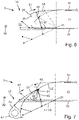
Figs. 5 to 7 differ from the embodiment shown inFig. 2 by astiffener 59 being provided at theleading edge portion 35 of theupper skin panel 31. Thestiffener 59 extends in aspan direction 29 in parallel to the axis ofrotation 21 and in parallel to the trailingedge 43 of thehigh lift body 15. - In the embodiments shown in
Fig. 5 and7 , thestiffener 59 is formed separately from theupper skin panel 31 and is attached to an inner surface of theleading edge portion 35 of theupper skin panel 31. Thestiffener 59 has an angled profile including aflange element 61 resting against the inner surface of theleading edge portion 35 of theupper skin panel 31, and aweb element 63 extending angled to theflange element 61 and away from the inner surface of theleading edge portion 35 of theupper skin panel 31. The angles profile in the present embodiment is an L-profile. - In the alternative embodiment shown in
Fig. 6 , thestiffener 59 is formed integral with theleading edge portion 35 of theupper skin panel 31. In case of theupper skin panel 31 being made of a metal material thestiffener 59 is formed by bending a part of theleading edge portion 35 of theupper skin panel 31. In case of theupper skin panel 31 being made of a fiber reinforced plastic material thestiffener 59 is moulded as part of theleading edge portion 35 of theupper skin panel 31. - In the embodiment shown in
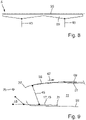
Fig. 7 , thelink element 45 is attached to theleading edge portion 35 of theupper skin panel 31 via thestiffener 59. As shown inFig. 8 , the extension of thestiffener 59 normal to theleading edge portion 35 of theupper skin panel 31 varies in thespan direction 29 in such a way that a maximum extension is in the area of the attachment of thelink element 45, while the extension is linearly decreasing in thespan direction 29 with increasing distance from the area of the attachment of thelink element 45. Likewise, a minimum extension is located centrally between thelink elements 45 of each two spanwiseneighboring connection assemblies 17. - The embodiment shown in
Fig. 9 differs from the embodiment shown inFig. 2 by theleading edge portion 35 of theupper skin panel 31 having a thickness varying in achord direction 67, to adjust the curvature of theleading edge portion 35 of theupper skin panel 31 when in the deformed state. This allows the thickness of theleading edge portion 35 of theupper skin panel 31 to be used to tailor the curvature of theupper skin panel 31 in the deformed state, i.e. when thehigh lift body 15 is in the deployed position. The thickness of theleading edge portion 35 of theupper skin panel 31 varies analogue to the bending moment resulting from elastic deformation of theleading edge portion 35 of theupper skin panel 31, in such a way that the varying bending stiffness along thechord direction 67 of theleading edge portion 35 of theupper skin panel 31, resulting from the varying thickness, compensates the bending moment. This means in the present embodiment, the thickness of theleading edge portion 35 of theupper skin panel 31 increases linearly or essentially linearly in thechord direction 67 downstream, so that a maximum thickness is reached at thedownstream end 69 of theleading edge portion 35 of theupper skin panel 31. - In case that the
leading edge portion 35 of theupper skin panel 31 being made of a fiber reinforced plastic, the linear thickness increase of theupper skin panel 31 might be implemented or assisted by theleading edge portion 35 of theupper skin panel 31 having a linearly increasing, e.g. ply-ramped, laminate lay-up (not shown) in thechord direction 67. Also, one or more reinforcement elements (not shown) attached to theleading edge portion 35 of theupper skin panel 31 might be used to implement or assist an increasing bending stiffness of theleading edge portion 35 of theupper skin panel 31 in the chord direction to compensate an increasing bending moment. - As shown in
Fig. 1 , the leading edgehigh lift assembly 13 comprises a further connection assembly 17' spaced from theconnection assembly 17 in thespan direction 29 and preferably formed as theconnection assembly 17. At least two spacedconnection assemblies 17, 17' are provided to carry eachhigh lift body 15. Eachconnection assembly 17, 17' might also comprise more than one rotation element 19. - By the invention as described above, a smooth transition from the trailing
edge 43 of thehigh lift body 15 to theupper skin panel 31 can be achieved avoiding small and discontinuous curvature radii. This results in a smooth pressure profile along theupper skin panel 31 without undesired pressure peaks. - 1
- aircraft
- 3
- fuselage
- 5
- wings
- 7
- vertical tail plane
- 9
- horizontal tail plane
- 11
- main wing
- 13
- high lift assembly
- 15
- high lift body
- 17
- connection assembly
- 17'
- further connection assembly
- 19
- rotation element
- 21
- axis of rotation
- 25
- hinge
- 27
- fixing link
- 29
- span direction
- 31
- upper skin panel
- 33
- lower skin panel
- 35
- leading edge portion
- 37
- open end
- 39
- front spar
- 41
- leading edge
- 43
- trailing edge
- 45
- link element
- 47
- actuator
- 49
- drive arm
- 51
- drive link
- 53
- first rotating arm
- 55
- second rotating arm
- 57
- common axis
- 59
- stiffener
- 61
- flange element
- 63
- web element
- 67
- chord direction
- 69
- downstream end of leding edge portion
Claims (20)
- A wing (5) for an aircraft (1), comprisinga main wing (11), anda leading edge high lift assembly (13) comprisinga high lift body (15), anda connection assembly (17) connecting the high lift body (15) to the main wing (11) in such a way that the high lift body (15) is movable relative to the main wing (11) between a stowed position and a deployed position,wherein the connection assembly (17) comprises at least one rotation element (19) that is mounted to the high lift body (15) and that is mounted to the main wing (11) rotatably about an axis of rotation (21),wherein the main wing (11) comprises an upper skin panel (31) and a lower skin panel (33), wherein the upper skin panel (31) has a leading edge portion (35),wherein the high lift body (15) extends between a leading edge (41) and a trailing edge (43), wherein the trailing edge (43) of the high lift body (15) is configured to move along the leading edge portion (35) of the upper skin panel (31) of the main wing (11), when the high lift body (15) is moved between the stowed position and the deployed position,characterized in thatthe leading edge portion (35) of the upper skin panel (31) is configured to be elastically deformed, when the high lift body (15) is moved from the stowed position to the deployed position.
- The wing (5) according to claim 1, wherein the leading edge portion (35) of the upper skin panel (31) is configured to be elastically deformed, when the high lift body (15) is moved from the stowed position to the deployed position, by at least one link element (45) rotatably mounted to the rotation element (19) and rotatably mounted to the leading edge portion (35) of the upper skin panel (31).
- The wing (5) according to claim 1 or 2, wherein the leading edge portion (35) of the upper skin panel (31) is configured to be elastically deformed, when the high lift body (15) is moved from the stowed position to the deployed position, by at least one rope element attached to the rotation element (19) and attached to the leading edge portion (35) of the upper skin panel (31).
- The wing (5) according to any of claims 1 to 3, wherein the leading edge portion (35) of the upper skin panel (31) is configured to be elastically deformed by the trailing edge (43) of the high lift body (15) moving along and contacting the leading edge portion (35) of the upper skin panel (31), when the high lift body (15) is moved from the stowed position to the deployed position.
- The wing (5) according to any of claims 1 to 4, wherein the wing (5) comprises a rotating actuator (47) for driving the rotation element (19) about the axis of rotation (21).
- The wing (5) according to claim 5, wherein the rotary actuator (47) is mounted to the main wing (11) and has a rotating drive arm (49) linked to the rotation element (19) by a drive link (51) that is rotatably mounted to the drive arm (49) and that is rotatably mounted to the rotation element (19).
- The wing (5) according to claim 5, wherein the rotary actuator (47) comprises a first rotating arm (53) and a second rotating arm (55) rotating in opposite directions about a common axis (57),wherein the first rotating arm (53) is rotatably mounted to the main wing (11), andwherein the second rotating arm (55) is rotatably mounted to the rotation element (19) or to the high lift body (15).
- The wing (5) according to any of claims 1 to 7, wherein at least one stiffener (59) is provided at the leading edge portion (35) of the upper skin panel (31),
wherein the stiffener (59) extends in a span direction (29). - The wing (5) according to claim 8, wherein the stiffener (59) is formed separately from the upper skin panel (31) and is attached to an inner surface of the leading edge portion (35) of the upper skin panel (31).
- The wing (5) according to claim 8, wherein the stiffener (59) is formed integral with the leading edge portion (35) of the upper skin panel (31).
- The wing (5) according to any of claims 8 to 10, when dependent from claim 2 or 3, wherein the link element (45) and/or the rope element is attached to the leading edge portion (35) of the upper skin panel (31)via the stiffener (59).
- The wing (5) according to any of claims 8 to 11, wherein the extension of the stiffener (59) normal to the upper skin panel (31) varies in the span direction (29).
- The wing (5) according to claim 12, when dependent from claim 2 or 3, wherein the extension of the stiffener (59) normal to the upper skin panel (31) varies in the span direction (29) in such a way that a maximum extension is in the area of the attachment of the link element (45) and/or the rope element, while the extension is decreasing in the span direction (29) with increasing distance from the area of the attachment of the link element (45) and/or the rope element.
- The wing (5) according to any of claims 1 to 13, wherein the leading edge portion (35) of the upper skin panel (31) has a thickness varying in a chord direction (67).
- The wing (5) according to claim 14, wherein the thickness of the leading edge portion (35) of the upper skin panel (31) increases linearly in the chord direction (67) downstream.
- The wing (5) according to any of claims 1 to 15, wherein the leading edge portion (35) of the upper skin panel (31) is made of a fiber reinforced plastic having a varying laminate lay-up in the chord direction (67).
- The wing (5) according to any of claims 1 to 16, wherein the leading edge portion (35) of the upper skin panel (31) is provided with at least one reinforcement element extending in the chord direction (67) to vary the bending stiffness of the leading edge portion (35) of the upper skin panel (31) along the chord direction (67).
- The wing (5) according to any of claims 1 to 17, wherein the leading edge high lift assembly (13) comprises a further connection assembly (17') spaced from the connection assembly (17) in the span direction (29).
- A leading edge high lift assembly (13) for the wing (5) according to any of claims 1 to 18, comprisinga high lift body (15), anda connection assembly (17) for connecting the high lift body (15) to a main wing (11) in such a way that the high lift body (15) is movable relative to the main wing (11) between a stowed position and a deployed position,wherein the connection assembly (17) comprises a rotation element (19) that is mounted to the high lift body (15) and that is configured to be mounted to the main wing (11) rotatably about an axis of rotation (21),wherein the high lift body (15) extends between a leading edge (41) and a trailing edge (43), wherein in an installed state the trailing edge (43) of the high lift body (15) is configured to move along the leading edge portion (35) of an upper skin panel (31) of the main wing (11), when the high lift body (15) is moved between the stowed position and the deployed position,characterized in thatthe leading edge high lift assembly (13) is configured such that in an installed state the leading edge portion (35) of the upper skin panel (31) can be elastically deformed, when the high lift body (15) is moved from the stowed position to the deployed position.
- An aircraft (1) comprising the wing (5) according to any of claims 1 to 18 and/or comprising the leading edge high lift assembly (13) according to claim 19.
Priority Applications (1)
| Application Number | Priority Date | Filing Date | Title |
|---|---|---|---|
| EP24211242.3A EP4484282A3 (en) | 2021-03-23 | 2022-03-08 | Wing for an aircraft |
Applications Claiming Priority (1)
| Application Number | Priority Date | Filing Date | Title |
|---|---|---|---|
| DE102021107277 | 2021-03-23 |
Related Child Applications (1)
| Application Number | Title | Priority Date | Filing Date |
|---|---|---|---|
| EP24211242.3A Division EP4484282A3 (en) | 2021-03-23 | 2022-03-08 | Wing for an aircraft |
Publications (2)
| Publication Number | Publication Date |
|---|---|
| EP4063257A1 true EP4063257A1 (en) | 2022-09-28 |
| EP4063257B1 EP4063257B1 (en) | 2024-11-27 |
Family
ID=80683630
Family Applications (2)
| Application Number | Title | Priority Date | Filing Date |
|---|---|---|---|
| EP22160772.4A Active EP4063257B1 (en) | 2021-03-23 | 2022-03-08 | Wing for an aircraft |
| EP24211242.3A Pending EP4484282A3 (en) | 2021-03-23 | 2022-03-08 | Wing for an aircraft |
Family Applications After (1)
| Application Number | Title | Priority Date | Filing Date |
|---|---|---|---|
| EP24211242.3A Pending EP4484282A3 (en) | 2021-03-23 | 2022-03-08 | Wing for an aircraft |
Country Status (2)
| Country | Link |
|---|---|
| US (1) | US12049314B2 (en) |
| EP (2) | EP4063257B1 (en) |
Cited By (3)
| Publication number | Priority date | Publication date | Assignee | Title |
|---|---|---|---|---|
| US20220396348A1 (en) * | 2019-11-18 | 2022-12-15 | Airbus Operations Gmbh | Slat arrangement for a wing of an aircraft |
| EP4703262A1 (en) * | 2024-08-29 | 2026-03-04 | AIRBUS Operations GmbH | Wing for an aircraft |
| DE102024130898A1 (en) | 2024-10-23 | 2026-04-23 | Airbus Operations Gmbh | SUPPORT ARRANGEMENT FOR A HIGH-LEVEL BODY, HIGH-LEVEL BODY ARRANGEMENT AS WINGS AND AIRCRAFT WITH IT |
Families Citing this family (2)
| Publication number | Priority date | Publication date | Assignee | Title |
|---|---|---|---|---|
| WO2021052908A1 (en) * | 2019-09-17 | 2021-03-25 | Airbus Operations Gmbh | Actuator arrangement for a fixed leading edge member of an aircraft, wing assembly and aircraft equipped with said actuator arrangement |
| CN119348808B (en) * | 2024-12-05 | 2025-09-30 | 中国航空工业集团公司西安飞机设计研究所 | A slat cover movement mechanism |
Citations (4)
| Publication number | Priority date | Publication date | Assignee | Title |
|---|---|---|---|---|
| US4200253A (en) * | 1977-04-06 | 1980-04-29 | British Aerospace | Aircraft wing drooping leading edge device |
| US4285482A (en) * | 1979-08-10 | 1981-08-25 | The Boeing Company | Wing leading edge high lift device |
| US5388788A (en) * | 1993-12-16 | 1995-02-14 | The Boeing Company | Hinge fairings for control surfaces |
| US20140246540A1 (en) * | 2011-06-28 | 2014-09-04 | Airbus Operations Gmbh | Airfoil with a main wing and a high-lift body and method for realizing adjusting movements of a high-lift body relative to a main wing |
Family Cites Families (10)
| Publication number | Priority date | Publication date | Assignee | Title |
|---|---|---|---|---|
| DE2907912C2 (en) * | 1979-03-01 | 1985-06-05 | Dornier Gmbh, 7990 Friedrichshafen | Transverse drive body with variable profiling, in particular nose parts of aircraft wings |
| US4553722A (en) * | 1982-12-30 | 1985-11-19 | The Boeing Company | Variable-camber airfoil |
| US5158252A (en) * | 1991-10-24 | 1992-10-27 | The Boeing Company | Three-position variable camber Krueger leading edge flap |
| DE102011001582B4 (en) | 2011-03-28 | 2016-07-28 | Deutsches Zentrum für Luft- und Raumfahrt e.V. | Adaptive slat |
| DE102011018906A1 (en) | 2011-04-28 | 2012-10-31 | Airbus Operations Gmbh | High lift system for an aircraft and method for influencing the high lift characteristics of an aircraft |
| US9598167B2 (en) * | 2014-03-04 | 2017-03-21 | The Boeing Company | Morphing airfoil leading edge |
| US20150353187A1 (en) | 2014-04-30 | 2015-12-10 | The Boeing Company | Leading edge assembly for an aircraft |
| DE102015103601A1 (en) | 2015-03-11 | 2016-09-15 | Deutsches Zentrum für Luft- und Raumfahrt e.V. | Wing with a main wing and a slat |
| CA3048431A1 (en) | 2019-07-03 | 2021-01-03 | Jaye Mangione | Deforming foil structure for bridging curved fluid-dynamic surface |
| US11420727B2 (en) | 2019-07-25 | 2022-08-23 | Airbus Operations Gmbh | Airfoil arrangement for an aircraft |
-
2022
- 2022-03-08 EP EP22160772.4A patent/EP4063257B1/en active Active
- 2022-03-08 EP EP24211242.3A patent/EP4484282A3/en active Pending
- 2022-03-21 US US17/699,312 patent/US12049314B2/en active Active
Patent Citations (4)
| Publication number | Priority date | Publication date | Assignee | Title |
|---|---|---|---|---|
| US4200253A (en) * | 1977-04-06 | 1980-04-29 | British Aerospace | Aircraft wing drooping leading edge device |
| US4285482A (en) * | 1979-08-10 | 1981-08-25 | The Boeing Company | Wing leading edge high lift device |
| US5388788A (en) * | 1993-12-16 | 1995-02-14 | The Boeing Company | Hinge fairings for control surfaces |
| US20140246540A1 (en) * | 2011-06-28 | 2014-09-04 | Airbus Operations Gmbh | Airfoil with a main wing and a high-lift body and method for realizing adjusting movements of a high-lift body relative to a main wing |
Cited By (4)
| Publication number | Priority date | Publication date | Assignee | Title |
|---|---|---|---|---|
| US20220396348A1 (en) * | 2019-11-18 | 2022-12-15 | Airbus Operations Gmbh | Slat arrangement for a wing of an aircraft |
| US12371150B2 (en) * | 2019-11-18 | 2025-07-29 | Airbus Operations Gmbh | Slat arrangement for a wing of an aircraft |
| EP4703262A1 (en) * | 2024-08-29 | 2026-03-04 | AIRBUS Operations GmbH | Wing for an aircraft |
| DE102024130898A1 (en) | 2024-10-23 | 2026-04-23 | Airbus Operations Gmbh | SUPPORT ARRANGEMENT FOR A HIGH-LEVEL BODY, HIGH-LEVEL BODY ARRANGEMENT AS WINGS AND AIRCRAFT WITH IT |
Also Published As
| Publication number | Publication date |
|---|---|
| EP4484282A3 (en) | 2025-03-19 |
| EP4063257B1 (en) | 2024-11-27 |
| EP4484282A2 (en) | 2025-01-01 |
| US20220306278A1 (en) | 2022-09-29 |
| US20240367774A1 (en) | 2024-11-07 |
| US12049314B2 (en) | 2024-07-30 |
Similar Documents
| Publication | Publication Date | Title |
|---|---|---|
| EP4484282A2 (en) | Wing for an aircraft | |
| CA2793044C (en) | Wing variable camber trailing edge tip | |
| US8245982B2 (en) | Wing | |
| US7258308B2 (en) | Method and apparatus for controlling airflow with a gapped trailing edge device having a flexible flow surface | |
| US4553722A (en) | Variable-camber airfoil | |
| US4650140A (en) | Wind edge movable airfoil having variable camber | |
| US8511611B2 (en) | Slot seal | |
| US11346446B2 (en) | Seal | |
| US10501166B2 (en) | Methods and apparatus to control a gap between movable aircraft wing components | |
| EP4140878B1 (en) | Leading edge high lift assembly and wing for an aircraft | |
| EP3461738B1 (en) | High-fowler flap actuation apparatus and related methods | |
| US6076775A (en) | Airfoil with a landing flap having a flexible trailing edge | |
| GB2186849A (en) | Leading edge arrangements for aircraft wings | |
| JP7191673B2 (en) | Seal plate for aerodynamic surfaces | |
| US12630284B2 (en) | Wing for an aircraft | |
| EP4703262A1 (en) | Wing for an aircraft | |
| EP1972547A1 (en) | Wing leading edge device | |
| US12612152B2 (en) | Wing for an aircraft | |
| US20240017817A1 (en) | Wing for an aircraft | |
| US11801930B2 (en) | Wing for aircraft | |
| EP4613637A1 (en) | Wing for an aircraft | |
| WO2021094169A1 (en) | Aircraft wings having moveable structures |
Legal Events
| Date | Code | Title | Description |
|---|---|---|---|
| PUAI | Public reference made under article 153(3) epc to a published international application that has entered the european phase |
Free format text: ORIGINAL CODE: 0009012 |
|
| STAA | Information on the status of an ep patent application or granted ep patent |
Free format text: STATUS: THE APPLICATION HAS BEEN PUBLISHED |
|
| AK | Designated contracting states |
Kind code of ref document: A1 Designated state(s): AL AT BE BG CH CY CZ DE DK EE ES FI FR GB GR HR HU IE IS IT LI LT LU LV MC MK MT NL NO PL PT RO RS SE SI SK SM TR |
|
| STAA | Information on the status of an ep patent application or granted ep patent |
Free format text: STATUS: REQUEST FOR EXAMINATION WAS MADE |
|
| 17P | Request for examination filed |
Effective date: 20230328 |
|
| RBV | Designated contracting states (corrected) |
Designated state(s): AL AT BE BG CH CY CZ DE DK EE ES FI FR GB GR HR HU IE IS IT LI LT LU LV MC MK MT NL NO PL PT RO RS SE SI SK SM TR |
|
| RIC1 | Information provided on ipc code assigned before grant |
Ipc: B64C 3/20 20060101ALN20240515BHEP Ipc: B64C 9/02 20060101ALI20240515BHEP Ipc: B64C 9/24 20060101ALI20240515BHEP Ipc: B64C 3/26 20060101AFI20240515BHEP |
|
| GRAP | Despatch of communication of intention to grant a patent |
Free format text: ORIGINAL CODE: EPIDOSNIGR1 |
|
| STAA | Information on the status of an ep patent application or granted ep patent |
Free format text: STATUS: GRANT OF PATENT IS INTENDED |
|
| RIC1 | Information provided on ipc code assigned before grant |
Ipc: B64C 3/20 20060101ALN20240613BHEP Ipc: B64C 9/02 20060101ALI20240613BHEP Ipc: B64C 9/24 20060101ALI20240613BHEP Ipc: B64C 3/26 20060101AFI20240613BHEP |
|
| INTG | Intention to grant announced |
Effective date: 20240625 |
|
| GRAS | Grant fee paid |
Free format text: ORIGINAL CODE: EPIDOSNIGR3 |
|
| GRAA | (expected) grant |
Free format text: ORIGINAL CODE: 0009210 |
|
| STAA | Information on the status of an ep patent application or granted ep patent |
Free format text: STATUS: THE PATENT HAS BEEN GRANTED |
|
| AK | Designated contracting states |
Kind code of ref document: B1 Designated state(s): AL AT BE BG CH CY CZ DE DK EE ES FI FR GB GR HR HU IE IS IT LI LT LU LV MC MK MT NL NO PL PT RO RS SE SI SK SM TR |
|
| REG | Reference to a national code |
Ref country code: GB Ref legal event code: FG4D |
|
| REG | Reference to a national code |
Ref country code: CH Ref legal event code: EP |
|
| REG | Reference to a national code |
Ref country code: IE Ref legal event code: FG4D |
|
| REG | Reference to a national code |
Ref country code: DE Ref legal event code: R096 Ref document number: 602022008049 Country of ref document: DE |
|
| REG | Reference to a national code |
Ref country code: LT Ref legal event code: MG9D |
|
| REG | Reference to a national code |
Ref country code: NL Ref legal event code: MP Effective date: 20241127 |
|
| PG25 | Lapsed in a contracting state [announced via postgrant information from national office to epo] |
Ref country code: PT Free format text: LAPSE BECAUSE OF FAILURE TO SUBMIT A TRANSLATION OF THE DESCRIPTION OR TO PAY THE FEE WITHIN THE PRESCRIBED TIME-LIMIT Effective date: 20250327 Ref country code: HR Free format text: LAPSE BECAUSE OF FAILURE TO SUBMIT A TRANSLATION OF THE DESCRIPTION OR TO PAY THE FEE WITHIN THE PRESCRIBED TIME-LIMIT Effective date: 20241127 Ref country code: IS Free format text: LAPSE BECAUSE OF FAILURE TO SUBMIT A TRANSLATION OF THE DESCRIPTION OR TO PAY THE FEE WITHIN THE PRESCRIBED TIME-LIMIT Effective date: 20250327 |
|
| PG25 | Lapsed in a contracting state [announced via postgrant information from national office to epo] |
Ref country code: FI Free format text: LAPSE BECAUSE OF FAILURE TO SUBMIT A TRANSLATION OF THE DESCRIPTION OR TO PAY THE FEE WITHIN THE PRESCRIBED TIME-LIMIT Effective date: 20241127 Ref country code: NL Free format text: LAPSE BECAUSE OF FAILURE TO SUBMIT A TRANSLATION OF THE DESCRIPTION OR TO PAY THE FEE WITHIN THE PRESCRIBED TIME-LIMIT Effective date: 20241127 |
|
| REG | Reference to a national code |
Ref country code: AT Ref legal event code: MK05 Ref document number: 1745481 Country of ref document: AT Kind code of ref document: T Effective date: 20241127 |
|
| PG25 | Lapsed in a contracting state [announced via postgrant information from national office to epo] |
Ref country code: BG Free format text: LAPSE BECAUSE OF FAILURE TO SUBMIT A TRANSLATION OF THE DESCRIPTION OR TO PAY THE FEE WITHIN THE PRESCRIBED TIME-LIMIT Effective date: 20241127 |
|
| PG25 | Lapsed in a contracting state [announced via postgrant information from national office to epo] |
Ref country code: ES Free format text: LAPSE BECAUSE OF FAILURE TO SUBMIT A TRANSLATION OF THE DESCRIPTION OR TO PAY THE FEE WITHIN THE PRESCRIBED TIME-LIMIT Effective date: 20241127 |
|
| PG25 | Lapsed in a contracting state [announced via postgrant information from national office to epo] |
Ref country code: NO Free format text: LAPSE BECAUSE OF FAILURE TO SUBMIT A TRANSLATION OF THE DESCRIPTION OR TO PAY THE FEE WITHIN THE PRESCRIBED TIME-LIMIT Effective date: 20250227 |
|
| PG25 | Lapsed in a contracting state [announced via postgrant information from national office to epo] |
Ref country code: GR Free format text: LAPSE BECAUSE OF FAILURE TO SUBMIT A TRANSLATION OF THE DESCRIPTION OR TO PAY THE FEE WITHIN THE PRESCRIBED TIME-LIMIT Effective date: 20250228 Ref country code: LV Free format text: LAPSE BECAUSE OF FAILURE TO SUBMIT A TRANSLATION OF THE DESCRIPTION OR TO PAY THE FEE WITHIN THE PRESCRIBED TIME-LIMIT Effective date: 20241127 Ref country code: AT Free format text: LAPSE BECAUSE OF FAILURE TO SUBMIT A TRANSLATION OF THE DESCRIPTION OR TO PAY THE FEE WITHIN THE PRESCRIBED TIME-LIMIT Effective date: 20241127 |
|
| PG25 | Lapsed in a contracting state [announced via postgrant information from national office to epo] |
Ref country code: PL Free format text: LAPSE BECAUSE OF FAILURE TO SUBMIT A TRANSLATION OF THE DESCRIPTION OR TO PAY THE FEE WITHIN THE PRESCRIBED TIME-LIMIT Effective date: 20241127 |
|
| PG25 | Lapsed in a contracting state [announced via postgrant information from national office to epo] |
Ref country code: RS Free format text: LAPSE BECAUSE OF FAILURE TO SUBMIT A TRANSLATION OF THE DESCRIPTION OR TO PAY THE FEE WITHIN THE PRESCRIBED TIME-LIMIT Effective date: 20250227 |
|
| PG25 | Lapsed in a contracting state [announced via postgrant information from national office to epo] |
Ref country code: SM Free format text: LAPSE BECAUSE OF FAILURE TO SUBMIT A TRANSLATION OF THE DESCRIPTION OR TO PAY THE FEE WITHIN THE PRESCRIBED TIME-LIMIT Effective date: 20241127 |
|
| PG25 | Lapsed in a contracting state [announced via postgrant information from national office to epo] |
Ref country code: DK Free format text: LAPSE BECAUSE OF FAILURE TO SUBMIT A TRANSLATION OF THE DESCRIPTION OR TO PAY THE FEE WITHIN THE PRESCRIBED TIME-LIMIT Effective date: 20241127 |
|
| PG25 | Lapsed in a contracting state [announced via postgrant information from national office to epo] |
Ref country code: EE Free format text: LAPSE BECAUSE OF FAILURE TO SUBMIT A TRANSLATION OF THE DESCRIPTION OR TO PAY THE FEE WITHIN THE PRESCRIBED TIME-LIMIT Effective date: 20241127 |
|
| PG25 | Lapsed in a contracting state [announced via postgrant information from national office to epo] |
Ref country code: RO Free format text: LAPSE BECAUSE OF FAILURE TO SUBMIT A TRANSLATION OF THE DESCRIPTION OR TO PAY THE FEE WITHIN THE PRESCRIBED TIME-LIMIT Effective date: 20241127 |
|
| PG25 | Lapsed in a contracting state [announced via postgrant information from national office to epo] |
Ref country code: SK Free format text: LAPSE BECAUSE OF FAILURE TO SUBMIT A TRANSLATION OF THE DESCRIPTION OR TO PAY THE FEE WITHIN THE PRESCRIBED TIME-LIMIT Effective date: 20241127 |
|
| PG25 | Lapsed in a contracting state [announced via postgrant information from national office to epo] |
Ref country code: CZ Free format text: LAPSE BECAUSE OF FAILURE TO SUBMIT A TRANSLATION OF THE DESCRIPTION OR TO PAY THE FEE WITHIN THE PRESCRIBED TIME-LIMIT Effective date: 20241127 |
|
| PG25 | Lapsed in a contracting state [announced via postgrant information from national office to epo] |
Ref country code: IT Free format text: LAPSE BECAUSE OF FAILURE TO SUBMIT A TRANSLATION OF THE DESCRIPTION OR TO PAY THE FEE WITHIN THE PRESCRIBED TIME-LIMIT Effective date: 20241127 |
|
| REG | Reference to a national code |
Ref country code: DE Ref legal event code: R097 Ref document number: 602022008049 Country of ref document: DE |
|
| PG25 | Lapsed in a contracting state [announced via postgrant information from national office to epo] |
Ref country code: SE Free format text: LAPSE BECAUSE OF FAILURE TO SUBMIT A TRANSLATION OF THE DESCRIPTION OR TO PAY THE FEE WITHIN THE PRESCRIBED TIME-LIMIT Effective date: 20241127 |
|
| PLBE | No opposition filed within time limit |
Free format text: ORIGINAL CODE: 0009261 |
|
| STAA | Information on the status of an ep patent application or granted ep patent |
Free format text: STATUS: NO OPPOSITION FILED WITHIN TIME LIMIT |
|
| REG | Reference to a national code |
Ref country code: CH Ref legal event code: L10 Free format text: ST27 STATUS EVENT CODE: U-0-0-L10-L00 (AS PROVIDED BY THE NATIONAL OFFICE) Effective date: 20251008 |
|
| PG25 | Lapsed in a contracting state [announced via postgrant information from national office to epo] |
Ref country code: MC Free format text: LAPSE BECAUSE OF FAILURE TO SUBMIT A TRANSLATION OF THE DESCRIPTION OR TO PAY THE FEE WITHIN THE PRESCRIBED TIME-LIMIT Effective date: 20241127 |
|
| REG | Reference to a national code |
Ref country code: CH Ref legal event code: H13 Free format text: ST27 STATUS EVENT CODE: U-0-0-H10-H13 (AS PROVIDED BY THE NATIONAL OFFICE) Effective date: 20251023 |
|
| 26N | No opposition filed |
Effective date: 20250828 |
|
| PG25 | Lapsed in a contracting state [announced via postgrant information from national office to epo] |
Ref country code: LU Free format text: LAPSE BECAUSE OF NON-PAYMENT OF DUE FEES Effective date: 20250308 |
|
| REG | Reference to a national code |
Ref country code: BE Ref legal event code: MM Effective date: 20250331 |
|
| PG25 | Lapsed in a contracting state [announced via postgrant information from national office to epo] |
Ref country code: BE Free format text: LAPSE BECAUSE OF NON-PAYMENT OF DUE FEES Effective date: 20250331 |
|
| PG25 | Lapsed in a contracting state [announced via postgrant information from national office to epo] |
Ref country code: CH Free format text: LAPSE BECAUSE OF NON-PAYMENT OF DUE FEES Effective date: 20250331 |
|
| PG25 | Lapsed in a contracting state [announced via postgrant information from national office to epo] |
Ref country code: IE Free format text: LAPSE BECAUSE OF NON-PAYMENT OF DUE FEES Effective date: 20250308 |
|
| PGFP | Annual fee paid to national office [announced via postgrant information from national office to epo] |
Ref country code: GB Payment date: 20260324 Year of fee payment: 5 |
|
| PGFP | Annual fee paid to national office [announced via postgrant information from national office to epo] |
Ref country code: DE Payment date: 20260319 Year of fee payment: 5 |
|
| PGFP | Annual fee paid to national office [announced via postgrant information from national office to epo] |
Ref country code: FR Payment date: 20260323 Year of fee payment: 5 |