EP4063248A1 - Car seat adaptor - Google Patents
Car seat adaptor Download PDFInfo
- Publication number
- EP4063248A1 EP4063248A1 EP22163760.6A EP22163760A EP4063248A1 EP 4063248 A1 EP4063248 A1 EP 4063248A1 EP 22163760 A EP22163760 A EP 22163760A EP 4063248 A1 EP4063248 A1 EP 4063248A1
- Authority
- EP
- European Patent Office
- Prior art keywords
- car seat
- spring
- support
- adaptor according
- seat adaptor
- Prior art date
- Legal status (The legal status is an assumption and is not a legal conclusion. Google has not performed a legal analysis and makes no representation as to the accuracy of the status listed.)
- Withdrawn
Links
Images


Classifications
-
- B—PERFORMING OPERATIONS; TRANSPORTING
- B60—VEHICLES IN GENERAL
- B60N—SEATS SPECIALLY ADAPTED FOR VEHICLES; VEHICLE PASSENGER ACCOMMODATION NOT OTHERWISE PROVIDED FOR
- B60N2/00—Seats specially adapted for vehicles; Arrangement or mounting of seats in vehicles
- B60N2/24—Seats specially adapted for vehicles; Arrangement or mounting of seats in vehicles for particular purposes or particular vehicles
- B60N2/26—Seats specially adapted for vehicles; Arrangement or mounting of seats in vehicles for particular purposes or particular vehicles for children
- B60N2/28—Seats readily mountable on, and dismountable from, existing seats or other parts of the vehicle
- B60N2/2842—Seats readily mountable on, and dismountable from, existing seats or other parts of the vehicle adapted to carry the child, when dismounted from the vehicle
- B60N2/2845—Seats readily mountable on, and dismountable from, existing seats or other parts of the vehicle adapted to carry the child, when dismounted from the vehicle having handles
-
- B—PERFORMING OPERATIONS; TRANSPORTING
- B60—VEHICLES IN GENERAL
- B60N—SEATS SPECIALLY ADAPTED FOR VEHICLES; VEHICLE PASSENGER ACCOMMODATION NOT OTHERWISE PROVIDED FOR
- B60N2/00—Seats specially adapted for vehicles; Arrangement or mounting of seats in vehicles
- B60N2/24—Seats specially adapted for vehicles; Arrangement or mounting of seats in vehicles for particular purposes or particular vehicles
- B60N2/26—Seats specially adapted for vehicles; Arrangement or mounting of seats in vehicles for particular purposes or particular vehicles for children
- B60N2/28—Seats readily mountable on, and dismountable from, existing seats or other parts of the vehicle
- B60N2/2821—Seats readily mountable on, and dismountable from, existing seats or other parts of the vehicle having a seat and a base part
-
- B—PERFORMING OPERATIONS; TRANSPORTING
- B60—VEHICLES IN GENERAL
- B60N—SEATS SPECIALLY ADAPTED FOR VEHICLES; VEHICLE PASSENGER ACCOMMODATION NOT OTHERWISE PROVIDED FOR
- B60N2/00—Seats specially adapted for vehicles; Arrangement or mounting of seats in vehicles
- B60N2/24—Seats specially adapted for vehicles; Arrangement or mounting of seats in vehicles for particular purposes or particular vehicles
- B60N2/26—Seats specially adapted for vehicles; Arrangement or mounting of seats in vehicles for particular purposes or particular vehicles for children
- B60N2/28—Seats readily mountable on, and dismountable from, existing seats or other parts of the vehicle
- B60N2/2842—Seats readily mountable on, and dismountable from, existing seats or other parts of the vehicle adapted to carry the child, when dismounted from the vehicle
- B60N2/2848—Seats readily mountable on, and dismountable from, existing seats or other parts of the vehicle adapted to carry the child, when dismounted from the vehicle being convertible or adaptable to a preambulator, e.g. a baby-carriage or a push-chair
-
- B—PERFORMING OPERATIONS; TRANSPORTING
- B62—LAND VEHICLES FOR TRAVELLING OTHERWISE THAN ON RAILS
- B62J—CYCLE SADDLES OR SEATS; AUXILIARY DEVICES OR ACCESSORIES SPECIALLY ADAPTED TO CYCLES AND NOT OTHERWISE PROVIDED FOR, e.g. ARTICLE CARRIERS OR CYCLE PROTECTORS
- B62J1/00—Saddles or other seats for cycles; Arrangement thereof; Component parts
- B62J1/08—Frames for saddles; Connections between saddle frames and seat pillars; Seat pillars
-
- B—PERFORMING OPERATIONS; TRANSPORTING
- B62—LAND VEHICLES FOR TRAVELLING OTHERWISE THAN ON RAILS
- B62J—CYCLE SADDLES OR SEATS; AUXILIARY DEVICES OR ACCESSORIES SPECIALLY ADAPTED TO CYCLES AND NOT OTHERWISE PROVIDED FOR, e.g. ARTICLE CARRIERS OR CYCLE PROTECTORS
- B62J1/00—Saddles or other seats for cycles; Arrangement thereof; Component parts
- B62J1/14—Separate pillions
- B62J1/16—Separate pillions for children
-
- B—PERFORMING OPERATIONS; TRANSPORTING
- B62—LAND VEHICLES FOR TRAVELLING OTHERWISE THAN ON RAILS
- B62K—CYCLES; CYCLE FRAMES; CYCLE STEERING DEVICES; RIDER-OPERATED TERMINAL CONTROLS SPECIALLY ADAPTED FOR CYCLES; CYCLE AXLE SUSPENSIONS; CYCLE SIDECARS, FORECARS, OR THE LIKE
- B62K7/00—Freight- or passenger-carrying cycles
-
- B—PERFORMING OPERATIONS; TRANSPORTING
- B62—LAND VEHICLES FOR TRAVELLING OTHERWISE THAN ON RAILS
- B62B—HAND-PROPELLED VEHICLES, e.g. HAND CARTS OR PERAMBULATORS; SLEDGES
- B62B7/00—Carriages for children; Perambulators, e.g. dolls' perambulators
- B62B7/04—Carriages for children; Perambulators, e.g. dolls' perambulators having more than one wheel axis; Steering devices therefor
- B62B7/14—Carriages for children; Perambulators, e.g. dolls' perambulators having more than one wheel axis; Steering devices therefor with detachable or rotatably-mounted body
- B62B7/142—Means for securing the body to the frame
-
- B—PERFORMING OPERATIONS; TRANSPORTING
- B62—LAND VEHICLES FOR TRAVELLING OTHERWISE THAN ON RAILS
- B62B—HAND-PROPELLED VEHICLES, e.g. HAND CARTS OR PERAMBULATORS; SLEDGES
- B62B7/00—Carriages for children; Perambulators, e.g. dolls' perambulators
- B62B7/04—Carriages for children; Perambulators, e.g. dolls' perambulators having more than one wheel axis; Steering devices therefor
- B62B7/14—Carriages for children; Perambulators, e.g. dolls' perambulators having more than one wheel axis; Steering devices therefor with detachable or rotatably-mounted body
- B62B7/145—Carriages for children; Perambulators, e.g. dolls' perambulators having more than one wheel axis; Steering devices therefor with detachable or rotatably-mounted body the body being a rigid seat, e.g. a shell
Definitions
- the invention relates to a car seat adaptor, e.g., for coupling a portable car seat to a cargo bike or similar vehicle.
- Portable car seats such as Maxi-Cosi ® car seats, have universal connector interfaces for engaging adaptors for use on a pram, a pushchair, a cargo bike or similar vehicle.
- WO 2017/013577 discloses such a car seat adaptor mounted in the cargo box of a cargo bike.
- This prior art car seat adaptor comprises two standing supports with top ends having fasteners adapted to engage the connector elements of the car seat. Increasing robustness of such an adaptor will reduce its shock absorbing capacity, making it safer but less comfortable for a child using the car seat.
- a car seat adaptor comprising a support frame with two parallel supports and a pair of couplers, both supports being provided with one of the couplers, with a spring suspension between the coupler and the respective support.
- the couplers can be provided with the universal car seat connection means used for most portable child car seats, e.g., latches providing a snap-fit connection.
- the carrier supports the car seat at two positions with a spring suspension. This significantly improves driving comfort for a child seated in the car seat.
- the parallel supports have tubular parts, for example at the top ends.
- the spring suspensions can comprise:
- the spring is a tension spring that can be tensioned in a tension direction
- the coupler, the core and the tubular part of the respective support form a sliding guide that allows sliding movement of the coupler relative to the support only in said tension direction.
- the cores of the spring suspensions guide sliding movement of the couplers relative to the support in a sliding direction coinciding with the longitudinal direction of the supports, contributing to improved damping of this relative movement.
- the spring allows balancing of the child's weight and impact loads during transport.
- the spring rate or spring stiffness of the spring can for example be in the range of about 1 to about 2 N/mm.
- the spring can be pretensioned, in particular to provide a substantially constant spring rate over the working range of the spring at least during normal use of the car seat adaptor. This controls movement of the child and the car seat and limits movement to a spring expansion of about 40 mm.
- the cores have a hollow, e.g., C-shaped cross section enclosing the respective spring.
- the core and the spring may for example have a length extending in longitudinal direction of the tubular support.
- the cores may for example comprise a slot, while the support comprises a shaft, such as a bolt, extending through the slot.
- the spring can be suspended to the shaft.
- the shaft can for example radially cross the tubular end of the support.
- the shaft can for example have an outer end forming the stop for limiting sliding movement of the coupler, the stop being slidable in the sliding direction within a chamber of the coupler. To this end the chamber will have a length in the sliding direction which is shorter than the length of the slot in the core of the spring suspension.
- This shaft can for example be a bolt with one end carrying a nut forming the stop.
- both couplers have a lower end slidably receiving the top end of the associated support and a top end comprising connection elements functionally matching with connecting elements of a car seat.
- the lower ends of the couplers may for example comprise two sections jointly fitting around the top end of the associated support. Covering the tubular ends provides an integrated design and contributes to a stable guiding of the sliding movement. Guiding of the sliding movement can be further improved if one of the sections of the coupler has an annular part slidably receiving the tubular top end of the respective support.
- the couplers can for example be of a suitable plastic, the sections being joint by means of a snap-fit.
- the support frame can a tubular frame.
- the two supports can be tubular over their full length and be bridged at their lower ends by a transversal tube of a length corresponding to the width of the car seat.
- the support frame can be an integral or bolted part of a vehicle, e.g., of an inner wall of a cargo box of a cargo bike.
- bolts can be used having a head with a lower edge received in a matching recess of a washer, to shield sharp edges of the bolt and to increase child safety.
- the washer can be a saddle washer, with a lower side following the contour of the respective support tube.
- the car seat carrier is particularly useful for coupling a car seat in a cargo box of a cargo bike, a normal bike or trike, or a similar vehicle, such as a pram or pushchair.
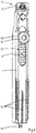
- Figure 1 shows a car seat adaptor 1 comprising a tubular support frame 2 with two parallel and symmetrically arranged upstanding tubular supports 3.
- the tubular supports 3 have lower ends bridged by a transversal tube 4.
- the top ends of the two supports 3 are capped by respective couplers 5 configured to connect to a universal connection mechanism used with most child car seats, such as those of Maxi-Cosi ® .
- the car seat adaptor 1 has a symmetrical build-up so the two couplers 5 have similar but mirrored configurations, just as the two supports 3.
- the two couplers 5 are connected to the supports 3 by means of a spring suspension 6, as shown in Figures 2 , 3 and 4 .
- the spring suspension 6 comprises a core 7 and a tension spring 8, jointly received within the tubular top end of the support 3.
- the top end of the core 7 is fixed to the respective coupler 5 by means of a bolt 9 at an inner side of the coupler 5.
- the lower end of the core 7 has a hook 10. Between the bolt 9 and the hook 10, the core 7 has a substantially C-shaped cross section with an open side 11 ( Figure 3 ) providing access for positioning the spring 8.
- the core 7 is also provided with a slot 12 ( Figure 4 ) opposite to the open side 11 and extending in a longitudinal direction of the core 7 between a point near the bolt 9 and a point about halfway the length of the core 7.
- Vertically extending ribs 13 space the core 7 from the inner wall of the tubular support 3 and serve to provide a low clearance sliding guide.
- the spring 8 is contained in the C-shaped cross section of the core 7.
- the spring 8 has a lower end with a loop 14 hooked to the hook 10 of the core 7 and a top end with a loop 15 suspended to a bolt 16 extending radially through bores 17 ( Figure 2 ) in the tubular support 3 crossing the slot 12 of the core 7.
- the bolt 16 has a bolt head 18 at one side of the support 3, and a threaded part carrying a nut 19 at an opposite side of the support 3.
- the spring can be balanced with the child's weight and impact loads during transport.
- Spring rate and pretension can for example be selected to limit spring expansion to about 40 mm.
- the nut 19 is slidably contained in a closed chamber 20 of the coupler 5, visible as a protruding box part on the outside of the coupler 5.
- the length of the chamber 20 is slightly shorter than the length of the slot 12, so the nut 19 serves as a stop or a sliding limiter.
- Both couplers 5 have a lower end slidably receiving the tubular top end of the associated support 3 with the nut 19, and a top end comprising universal connection elements 21 matching with the usual connecting elements of a car seat.
- the couplers 5 comprise two sections 22, 23 jointly fitting around the top end of the associated support 3.
- the two sections 22, 23 are coupled by a snap fit connection extending along a vertical plane and are typically made of an injection moulded plastic.
- the two sections 22, 23 include a main section 22 with the connection elements 21, and a cap section 23.
- the main section 22 is fixed to the core 7 and contains the chamber 20 covering the nut 19.
- the cap section 23 connects to a lower half of the main section 22 in order to cover the top end of the tubular support 3 and the bolt head 19, so as to hide these from view.
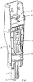
- the main section 23 has an annular part 24 ( Figure 5 ) slidably receiving the tubular top end of the respective support 3, so as to provide further guiding for proper joint sliding movement of the two couplers 5.
- the cap sections 23 of the couplers 5 face each other, just as the universal connection elements 21, while the protruding chambers 20 encasing the nuts 19 point away from each other.
- a car seat provided with the matching universal connection means can easily be clicked onto the couplers 5.
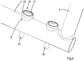
- the support frame 2 can be bolted to a vehicle, e.g., to an inner wall of a cargo box 25 of a cargo bike, as shown in Figure 7 .
- the frame 2 is mounted using a number of allen screw bolts 26, shown in detail in Figure 6 .
- each allen screw bolt 26 has a head 27 with a lower edge received in a matching recess 28 of a saddle washer 29.
- the saddle washer 29 has a lower edge 30 following the surface curvature of the tubular support 3.
- the saddle washer 29 can for example be made of an elastomeric or plastic material.
- the two supports 3 of the tubular frame 2 are slightly kinked at an obtuse angle.
- the car seat adaptor 1 is mounted in the cargo box 25 in a position that the lower ends 31 of the supports 3 are substantially vertical, while the kinked upper ends 32 are directed slightly forward, e.g., slightly towards a steer of the cargo bike. In this position a car seat can easily be clicked upon the car seat adaptor 1 with the sitting child facing the driver.
Landscapes
- Engineering & Computer Science (AREA)
- Mechanical Engineering (AREA)
- Health & Medical Sciences (AREA)
- Child & Adolescent Psychology (AREA)
- General Health & Medical Sciences (AREA)
- Aviation & Aerospace Engineering (AREA)
- Transportation (AREA)
- Seats For Vehicles (AREA)
Abstract
Description
- The invention relates to a car seat adaptor, e.g., for coupling a portable car seat to a cargo bike or similar vehicle.
- Portable car seats, such as Maxi-Cosi® car seats, have universal connector interfaces for engaging adaptors for use on a pram, a pushchair, a cargo bike or similar vehicle.
WO 2017/013577 discloses such a car seat adaptor mounted in the cargo box of a cargo bike. This prior art car seat adaptor comprises two standing supports with top ends having fasteners adapted to engage the connector elements of the car seat. Increasing robustness of such an adaptor will reduce its shock absorbing capacity, making it safer but less comfortable for a child using the car seat. - It is an object of the invention to provide a car seat adaptor allowing to couple a car seat to a vehicle with increased safety and driving comfort.
- The object of the invention is achieved with a car seat adaptor comprising a support frame with two parallel supports and a pair of couplers, both supports being provided with one of the couplers, with a spring suspension between the coupler and the respective support. The couplers can be provided with the universal car seat connection means used for most portable child car seats, e.g., latches providing a snap-fit connection. The carrier supports the car seat at two positions with a spring suspension. This significantly improves driving comfort for a child seated in the car seat.
- In a specific embodiment, the parallel supports have tubular parts, for example at the top ends. In such an embodiment, the spring suspensions can comprise:
- a core slidably received in the tubular part of the respective support, the core being mounted to the respective coupler; and
- a spring with a lower end connected to the core and an upper end fixed relative to the associated support. The weight of a child in the car seat will load the spring, for instance in addition to a possible pretension load.
- In a specific embodiment, the spring is a tension spring that can be tensioned in a tension direction, and the coupler, the core and the tubular part of the respective support form a sliding guide that allows sliding movement of the coupler relative to the support only in said tension direction. The cores of the spring suspensions guide sliding movement of the couplers relative to the support in a sliding direction coinciding with the longitudinal direction of the supports, contributing to improved damping of this relative movement.
- The spring allows balancing of the child's weight and impact loads during transport. The spring rate or spring stiffness of the spring can for example be in the range of about 1 to about 2 N/mm.
- Optionally, the spring can be pretensioned, in particular to provide a substantially constant spring rate over the working range of the spring at least during normal use of the car seat adaptor. This controls movement of the child and the car seat and limits movement to a spring expansion of about 40 mm.
- A compact arrangement is achieved if the cores have a hollow, e.g., C-shaped cross section enclosing the respective spring. The core and the spring may for example have a length extending in longitudinal direction of the tubular support.
- The cores may for example comprise a slot, while the support comprises a shaft, such as a bolt, extending through the slot. The spring can be suspended to the shaft. The shaft can for example radially cross the tubular end of the support. The shaft can for example have an outer end forming the stop for limiting sliding movement of the coupler, the stop being slidable in the sliding direction within a chamber of the coupler. To this end the chamber will have a length in the sliding direction which is shorter than the length of the slot in the core of the spring suspension. This shaft can for example be a bolt with one end carrying a nut forming the stop.
- In a specific embodiment, both couplers have a lower end slidably receiving the top end of the associated support and a top end comprising connection elements functionally matching with connecting elements of a car seat. To cover the support ends, the lower ends of the couplers may for example comprise two sections jointly fitting around the top end of the associated support. Covering the tubular ends provides an integrated design and contributes to a stable guiding of the sliding movement. Guiding of the sliding movement can be further improved if one of the sections of the coupler has an annular part slidably receiving the tubular top end of the respective support.
- The couplers can for example be of a suitable plastic, the sections being joint by means of a snap-fit.
- In a specific embodiment, the support frame can a tubular frame. For example the two supports can be tubular over their full length and be bridged at their lower ends by a transversal tube of a length corresponding to the width of the car seat. The support frame can be an integral or bolted part of a vehicle, e.g., of an inner wall of a cargo box of a cargo bike. To this end, bolts can be used having a head with a lower edge received in a matching recess of a washer, to shield sharp edges of the bolt and to increase child safety. The washer can be a saddle washer, with a lower side following the contour of the respective support tube.
- The car seat carrier is particularly useful for coupling a car seat in a cargo box of a cargo bike, a normal bike or trike, or a similar vehicle, such as a pram or pushchair.
- The invention will now be further explained with reference to the accompanying drawings, showing an exemplary embodiment of a car seat adaptor.
- Figure 1:
- shows a car seat adaptor according to the invention in perspective view;
- Figure 2:
- shows one of the couplers of the car seat adaptor in exploded view;
- Figure 3:
- shows a spring suspension of the coupler of
Figure 2 ; - Figure 4:
- shows the spring suspension of
Figure 3 from another viewing angle; - Figure 5:
- shows the coupler with one section broken away;
- Figure 6:
- shows in detail the connection to a vehicle;
- Figure 7:
- shows a cargo bike comprising the car seat adaptor.
-
Figure 1 shows acar seat adaptor 1 comprising atubular support frame 2 with two parallel and symmetrically arranged upstandingtubular supports 3. Thetubular supports 3 have lower ends bridged by atransversal tube 4. The top ends of the twosupports 3 are capped byrespective couplers 5 configured to connect to a universal connection mechanism used with most child car seats, such as those of Maxi-Cosi®. Thecar seat adaptor 1 has a symmetrical build-up so the twocouplers 5 have similar but mirrored configurations, just as the two supports 3. - The two
couplers 5 are connected to thesupports 3 by means of aspring suspension 6, as shown inFigures 2 ,3 and4 . Thespring suspension 6 comprises acore 7 and atension spring 8, jointly received within the tubular top end of thesupport 3. The top end of thecore 7 is fixed to therespective coupler 5 by means of abolt 9 at an inner side of thecoupler 5. The lower end of thecore 7 has ahook 10. Between thebolt 9 and thehook 10, thecore 7 has a substantially C-shaped cross section with an open side 11 (Figure 3 ) providing access for positioning thespring 8. Thecore 7 is also provided with a slot 12 (Figure 4 ) opposite to theopen side 11 and extending in a longitudinal direction of thecore 7 between a point near thebolt 9 and a point about halfway the length of thecore 7. Vertically extending ribs 13 (Figure 4 ) space thecore 7 from the inner wall of thetubular support 3 and serve to provide a low clearance sliding guide. - The
spring 8 is contained in the C-shaped cross section of thecore 7. Thespring 8 has a lower end with aloop 14 hooked to thehook 10 of thecore 7 and a top end with aloop 15 suspended to abolt 16 extending radially through bores 17 (Figure 2 ) in thetubular support 3 crossing theslot 12 of thecore 7. Thebolt 16 has abolt head 18 at one side of thesupport 3, and a threaded part carrying anut 19 at an opposite side of thesupport 3. - With this construction, the lower end of the
spring 8 moves with thecore 7 and thecoupler 5, while the top end of thespring 8 is fixed relative to thesupport 3. As a result, thecouplers 5 can resiliently move up and down relative to thesupport 3. - The spring can be balanced with the child's weight and impact loads during transport. Spring rate and pretension can for example be selected to limit spring expansion to about 40 mm.
- The
nut 19 is slidably contained in aclosed chamber 20 of thecoupler 5, visible as a protruding box part on the outside of thecoupler 5. The length of thechamber 20 is slightly shorter than the length of theslot 12, so thenut 19 serves as a stop or a sliding limiter. - Both
couplers 5 have a lower end slidably receiving the tubular top end of the associatedsupport 3 with thenut 19, and a top end comprisinguniversal connection elements 21 matching with the usual connecting elements of a car seat. At their lower ends, thecouplers 5 comprise twosections support 3. The twosections sections main section 22 with theconnection elements 21, and acap section 23. Themain section 22 is fixed to thecore 7 and contains thechamber 20 covering thenut 19. Thecap section 23 connects to a lower half of themain section 22 in order to cover the top end of thetubular support 3 and thebolt head 19, so as to hide these from view. - The
main section 23 has an annular part 24 (Figure 5 ) slidably receiving the tubular top end of therespective support 3, so as to provide further guiding for proper joint sliding movement of the twocouplers 5. - In the assembled state, the
cap sections 23 of thecouplers 5 face each other, just as theuniversal connection elements 21, while the protrudingchambers 20 encasing the nuts 19 point away from each other. In this position of thecouplers 5, a car seat provided with the matching universal connection means can easily be clicked onto thecouplers 5. - The
support frame 2 can be bolted to a vehicle, e.g., to an inner wall of acargo box 25 of a cargo bike, as shown inFigure 7 . Theframe 2 is mounted using a number ofallen screw bolts 26, shown in detail inFigure 6 . To optimize child safety, eachallen screw bolt 26 has ahead 27 with a lower edge received in amatching recess 28 of asaddle washer 29. Thesaddle washer 29 has alower edge 30 following the surface curvature of thetubular support 3. Thesaddle washer 29 can for example be made of an elastomeric or plastic material. - The two
supports 3 of thetubular frame 2 are slightly kinked at an obtuse angle. Thecar seat adaptor 1 is mounted in thecargo box 25 in a position that the lower ends 31 of thesupports 3 are substantially vertical, while the kinked upper ends 32 are directed slightly forward, e.g., slightly towards a steer of the cargo bike. In this position a car seat can easily be clicked upon thecar seat adaptor 1 with the sitting child facing the driver. - The terms "upward", "downward", "below", "above", "top", "lower", "vertical" and the like relate to the position of the respective parts in an assembled state of the
car seat adaptor 1 during normal use.
Claims (16)
- Car seat adaptor (1) comprising a support frame (2) with two parallel supports (3), and a pair of couplers (5), both supports being provided with one of the couplers and with a spring suspension (6) between the coupler and the respective support.
- Car seat adaptor according to claim 1, wherein at least one of the spring suspensions comprises:- a core (7) slidably received in a tubular part of the respective support, the core being mounted to the respective coupler; and- a spring (8) with one end (14) connected to the core and an opposite end (15) fixed relative to the associated support (3).
- Car seat adaptor according to claim 2, wherein the spring is a tension spring that can be tensioned in a tension direction, and wherein the coupler (5), the core (7) and the tubular part of the respective support (3) form a sliding guide that allows sliding movement of the coupler (5) relative to the support only in said tension direction.
- Car seat adaptor according to claim 3, wherein the tension spring has a spring rate or stiffness of about 1 to about 2 N/mm.
- Car seat adaptor according to claim 4, wherein the spring is pretensioned.
- Car seat adaptor according to claim 2, 3, 4 or 5, further comprising a stop (19, 20) limiting sliding movement of the coupler (5) relative to the support (3).
- Car seat adaptor according to claim 2, 3, 4, 5 or 6, wherein the core (7) has a hollow, e.g., C-shaped cross section at least partly enclosing the spring (8).
- Car seat adaptor according to claim 7, wherein the core (7) has a slot (12) and the support comprises a shaft (16), such as a bolt, extending through the slot (12), and wherein the spring (8) is suspended to the shaft (16).
- Car seat according to claim 8, wherein the shaft (16) crosses the support (3) and has an outer end forming the stop (19) for limiting sliding movement of the coupler (5), the stop being slidably encased in a chamber (20) of the coupler (5).
- Car seat adaptor according to claim 9, the shaft being a bolt (16) and the stop being a nut (19).
- Car seat adaptor according to any one of the preceding claims, wherein both couplers (5) have a lower end receiving and guiding the associated support (3), and a top end comprising connection elements (21) functionally matching with connecting elements of a car seat.
- Car seat adaptor according to claim 11, wherein the couplers (5) comprise two sections (22, 23) jointly fitting around the top end of the associated support (3).
- Car seat adaptor according to claim 12, wherein one of the sections (22, 23) of the coupler (5) has an annular part (24) slidably receiving the tubular top end of the respective support (3).
- Car seat adaptor according to any one of the preceding claims, wherein the support frame (2) is an integral or bolted part of a vehicle, e.g., of an inner wall of a cargo box (25) of a cargo bike.
- Car seat adaptor according to claim 14, wherein the support frame is bolted by means of fasteners, each fastener having a head with a lower edge received in a matching recess (28) of a washer (29), in particular a saddle washer.
- Cargo bike with a cargo box (25) provided with a car seat adaptor according to any one of the preceding claims.
Applications Claiming Priority (1)
| Application Number | Priority Date | Filing Date | Title |
|---|---|---|---|
| NL2027845A NL2027845B1 (en) | 2021-03-26 | 2021-03-26 | Car seat adaptor |
Publications (1)
| Publication Number | Publication Date |
|---|---|
| EP4063248A1 true EP4063248A1 (en) | 2022-09-28 |
Family
ID=76035094
Family Applications (1)
| Application Number | Title | Priority Date | Filing Date |
|---|---|---|---|
| EP22163760.6A Withdrawn EP4063248A1 (en) | 2021-03-26 | 2022-03-23 | Car seat adaptor |
Country Status (3)
| Country | Link |
|---|---|
| US (1) | US20220305967A1 (en) |
| EP (1) | EP4063248A1 (en) |
| NL (1) | NL2027845B1 (en) |
Citations (3)
| Publication number | Priority date | Publication date | Assignee | Title |
|---|---|---|---|---|
| GB2418225A (en) * | 2004-09-16 | 2006-03-22 | Ford Global Tech Llc | A bayonet type releasable fastening for a child car seat |
| KR20100025835A (en) * | 2008-08-28 | 2010-03-10 | 유영숙 | Stroller with a separable seat |
| WO2017013577A2 (en) | 2015-07-21 | 2017-01-26 | Taga Bikes Ltd | Cargo cycle with passenger seats |
Family Cites Families (4)
| Publication number | Priority date | Publication date | Assignee | Title |
|---|---|---|---|---|
| DE19521889C2 (en) * | 1995-06-16 | 1997-07-03 | Daimler Benz Ag | Device for quick attachment of a child seat |
| US5794951A (en) * | 1996-10-25 | 1998-08-18 | Century Products Company | Child's stroller with manually operable accessory latch assembly |
| FR2878814A1 (en) * | 2004-12-07 | 2006-06-09 | Profil Style Automobile Soc Pa | Equipment module e.g. armrest, fixing device for passenger transport motor vehicle, has connection bar with angle bracket and units fixed to rod, where bracket has arm extending from bar and having opening for fixation to module |
| US7401834B2 (en) * | 2005-07-13 | 2008-07-22 | Gm Global Technology Operations, Inc. | Child seat anchor assembly and methods of use |
-
2021
- 2021-03-26 NL NL2027845A patent/NL2027845B1/en active
-
2022
- 2022-02-28 US US17/682,798 patent/US20220305967A1/en not_active Abandoned
- 2022-03-23 EP EP22163760.6A patent/EP4063248A1/en not_active Withdrawn
Patent Citations (3)
| Publication number | Priority date | Publication date | Assignee | Title |
|---|---|---|---|---|
| GB2418225A (en) * | 2004-09-16 | 2006-03-22 | Ford Global Tech Llc | A bayonet type releasable fastening for a child car seat |
| KR20100025835A (en) * | 2008-08-28 | 2010-03-10 | 유영숙 | Stroller with a separable seat |
| WO2017013577A2 (en) | 2015-07-21 | 2017-01-26 | Taga Bikes Ltd | Cargo cycle with passenger seats |
Also Published As
| Publication number | Publication date |
|---|---|
| US20220305967A1 (en) | 2022-09-29 |
| NL2027845B1 (en) | 2022-10-10 |
Similar Documents
| Publication | Publication Date | Title |
|---|---|---|
| US7963541B2 (en) | Bicycle assembly with rear shock | |
| US6857674B2 (en) | Device and system for filtering vibrational movements of a passenger support, and passenger support equipped with such a system | |
| US8439383B2 (en) | Bicycle shock with extension arms | |
| US7784809B2 (en) | Motorcycle having a front wheel suspension | |
| US8485541B2 (en) | Suspension for a tricycle | |
| EP1631474B1 (en) | Low profile seat suspension | |
| US20100244405A1 (en) | Light Transport Vehicle | |
| US4779893A (en) | Strut type vehicle wheel suspension | |
| EP1987969A2 (en) | Shackle assembly | |
| WO2017021181A1 (en) | Pneumatic axle suspension for a rear axle of a vehicle | |
| AU2019202006B2 (en) | Suspension system for stroller | |
| MXPA96002393A (en) | Connector system for mounting an exhaust pipe to a truck cab. | |
| EP3121036B1 (en) | Pneumatic axle suspension for a rear axle of a vehicle | |
| US20110037300A1 (en) | Shock-absorbing seat system | |
| US20200377169A1 (en) | Bicycle Suspension | |
| US4523659A (en) | Rear suspension for a motorcycle | |
| AU2017201727B2 (en) | Seat attachment structure of saddle riding vehicle | |
| EP4063248A1 (en) | Car seat adaptor | |
| EP2819911B1 (en) | Connecting device for connecting a vehicle sub-frame and a vehicle body and vehicle comprising the same | |
| US7516971B2 (en) | Bicycle fork, bicycle frame and method for producing a bicycle frame | |
| US7837261B2 (en) | Seat arrangement | |
| CN220594566U (en) | Vehicle suspension device | |
| IT202100021803A1 (en) | Frame Assembly, Frame and Motor Assembly, Electric Bicycle | |
| GB2405623A (en) | Front wheel suspension and steering system for motorcycles and other vehicles | |
| KR102201633B1 (en) | Suspension of forklift seat |
Legal Events
| Date | Code | Title | Description |
|---|---|---|---|
| PUAI | Public reference made under article 153(3) epc to a published international application that has entered the european phase |
Free format text: ORIGINAL CODE: 0009012 |
|
| STAA | Information on the status of an ep patent application or granted ep patent |
Free format text: STATUS: THE APPLICATION HAS BEEN PUBLISHED |
|
| AK | Designated contracting states |
Kind code of ref document: A1 Designated state(s): AL AT BE BG CH CY CZ DE DK EE ES FI FR GB GR HR HU IE IS IT LI LT LU LV MC MK MT NL NO PL PT RO RS SE SI SK SM TR |
|
| STAA | Information on the status of an ep patent application or granted ep patent |
Free format text: STATUS: REQUEST FOR EXAMINATION WAS MADE |
|
| 17P | Request for examination filed |
Effective date: 20230118 |
|
| RBV | Designated contracting states (corrected) |
Designated state(s): AL AT BE BG CH CY CZ DE DK EE ES FI FR GB GR HR HU IE IS IT LI LT LU LV MC MK MT NL NO PL PT RO RS SE SI SK SM TR |
|
| STAA | Information on the status of an ep patent application or granted ep patent |
Free format text: STATUS: EXAMINATION IS IN PROGRESS |
|
| 17Q | First examination report despatched |
Effective date: 20230424 |
|
| REG | Reference to a national code |
Ref country code: DE Ref legal event code: R079 Free format text: PREVIOUS MAIN CLASS: B62K0007020000 Ipc: B62J0001080000 |
|
| GRAP | Despatch of communication of intention to grant a patent |
Free format text: ORIGINAL CODE: EPIDOSNIGR1 |
|
| STAA | Information on the status of an ep patent application or granted ep patent |
Free format text: STATUS: GRANT OF PATENT IS INTENDED |
|
| RIC1 | Information provided on ipc code assigned before grant |
Ipc: B62B 7/14 20060101ALI20240307BHEP Ipc: B60N 2/28 20060101ALI20240307BHEP Ipc: B62K 7/00 20060101ALI20240307BHEP Ipc: B62J 1/16 20060101ALI20240307BHEP Ipc: B62J 1/08 20060101AFI20240307BHEP |
|
| INTG | Intention to grant announced |
Effective date: 20240405 |
|
| STAA | Information on the status of an ep patent application or granted ep patent |
Free format text: STATUS: THE APPLICATION IS DEEMED TO BE WITHDRAWN |
|
| 18D | Application deemed to be withdrawn |
Effective date: 20240806 |