EP4063214A1 - Method and device for collision avoidance control in automatic lane change, vehicle, and storage medium - Google Patents
Method and device for collision avoidance control in automatic lane change, vehicle, and storage medium Download PDFInfo
- Publication number
- EP4063214A1 EP4063214A1 EP21830010.1A EP21830010A EP4063214A1 EP 4063214 A1 EP4063214 A1 EP 4063214A1 EP 21830010 A EP21830010 A EP 21830010A EP 4063214 A1 EP4063214 A1 EP 4063214A1
- Authority
- EP
- European Patent Office
- Prior art keywords
- current vehicle
- time period
- detection time
- vehicle
- safety detection
- Prior art date
- Legal status (The legal status is an assumption and is not a legal conclusion. Google has not performed a legal analysis and makes no representation as to the accuracy of the status listed.)
- Granted
Links
Images


Classifications
-
- B—PERFORMING OPERATIONS; TRANSPORTING
- B60—VEHICLES IN GENERAL
- B60W—CONJOINT CONTROL OF VEHICLE SUB-UNITS OF DIFFERENT TYPE OR DIFFERENT FUNCTION; CONTROL SYSTEMS SPECIALLY ADAPTED FOR HYBRID VEHICLES; ROAD VEHICLE DRIVE CONTROL SYSTEMS FOR PURPOSES NOT RELATED TO THE CONTROL OF A PARTICULAR SUB-UNIT
- B60W30/00—Purposes of road vehicle drive control systems not related to the control of a particular sub-unit, e.g. of systems using conjoint control of vehicle sub-units
- B60W30/08—Active safety systems predicting or avoiding probable or impending collision or attempting to minimise its consequences
- B60W30/09—Taking automatic action to avoid collision, e.g. braking and steering
-
- B—PERFORMING OPERATIONS; TRANSPORTING
- B60—VEHICLES IN GENERAL
- B60W—CONJOINT CONTROL OF VEHICLE SUB-UNITS OF DIFFERENT TYPE OR DIFFERENT FUNCTION; CONTROL SYSTEMS SPECIALLY ADAPTED FOR HYBRID VEHICLES; ROAD VEHICLE DRIVE CONTROL SYSTEMS FOR PURPOSES NOT RELATED TO THE CONTROL OF A PARTICULAR SUB-UNIT
- B60W30/00—Purposes of road vehicle drive control systems not related to the control of a particular sub-unit, e.g. of systems using conjoint control of vehicle sub-units
- B60W30/18—Propelling the vehicle
- B60W30/18009—Propelling the vehicle related to particular drive situations
- B60W30/18163—Lane change; Overtaking manoeuvres
-
- B—PERFORMING OPERATIONS; TRANSPORTING
- B60—VEHICLES IN GENERAL
- B60W—CONJOINT CONTROL OF VEHICLE SUB-UNITS OF DIFFERENT TYPE OR DIFFERENT FUNCTION; CONTROL SYSTEMS SPECIALLY ADAPTED FOR HYBRID VEHICLES; ROAD VEHICLE DRIVE CONTROL SYSTEMS FOR PURPOSES NOT RELATED TO THE CONTROL OF A PARTICULAR SUB-UNIT
- B60W30/00—Purposes of road vehicle drive control systems not related to the control of a particular sub-unit, e.g. of systems using conjoint control of vehicle sub-units
- B60W30/08—Active safety systems predicting or avoiding probable or impending collision or attempting to minimise its consequences
- B60W30/095—Predicting travel path or likelihood of collision
-
- B—PERFORMING OPERATIONS; TRANSPORTING
- B60—VEHICLES IN GENERAL
- B60W—CONJOINT CONTROL OF VEHICLE SUB-UNITS OF DIFFERENT TYPE OR DIFFERENT FUNCTION; CONTROL SYSTEMS SPECIALLY ADAPTED FOR HYBRID VEHICLES; ROAD VEHICLE DRIVE CONTROL SYSTEMS FOR PURPOSES NOT RELATED TO THE CONTROL OF A PARTICULAR SUB-UNIT
- B60W30/00—Purposes of road vehicle drive control systems not related to the control of a particular sub-unit, e.g. of systems using conjoint control of vehicle sub-units
- B60W30/08—Active safety systems predicting or avoiding probable or impending collision or attempting to minimise its consequences
- B60W30/095—Predicting travel path or likelihood of collision
- B60W30/0953—Predicting travel path or likelihood of collision the prediction being responsive to vehicle dynamic parameters
-
- B—PERFORMING OPERATIONS; TRANSPORTING
- B60—VEHICLES IN GENERAL
- B60W—CONJOINT CONTROL OF VEHICLE SUB-UNITS OF DIFFERENT TYPE OR DIFFERENT FUNCTION; CONTROL SYSTEMS SPECIALLY ADAPTED FOR HYBRID VEHICLES; ROAD VEHICLE DRIVE CONTROL SYSTEMS FOR PURPOSES NOT RELATED TO THE CONTROL OF A PARTICULAR SUB-UNIT
- B60W30/00—Purposes of road vehicle drive control systems not related to the control of a particular sub-unit, e.g. of systems using conjoint control of vehicle sub-units
- B60W30/08—Active safety systems predicting or avoiding probable or impending collision or attempting to minimise its consequences
- B60W30/095—Predicting travel path or likelihood of collision
- B60W30/0956—Predicting travel path or likelihood of collision the prediction being responsive to traffic or environmental parameters
-
- B—PERFORMING OPERATIONS; TRANSPORTING
- B60—VEHICLES IN GENERAL
- B60W—CONJOINT CONTROL OF VEHICLE SUB-UNITS OF DIFFERENT TYPE OR DIFFERENT FUNCTION; CONTROL SYSTEMS SPECIALLY ADAPTED FOR HYBRID VEHICLES; ROAD VEHICLE DRIVE CONTROL SYSTEMS FOR PURPOSES NOT RELATED TO THE CONTROL OF A PARTICULAR SUB-UNIT
- B60W40/00—Estimation or calculation of non-directly measurable driving parameters for road vehicle drive control systems not related to the control of a particular sub unit, e.g. by using mathematical models
- B60W40/02—Estimation or calculation of non-directly measurable driving parameters for road vehicle drive control systems not related to the control of a particular sub unit, e.g. by using mathematical models related to ambient conditions
-
- B—PERFORMING OPERATIONS; TRANSPORTING
- B60—VEHICLES IN GENERAL
- B60W—CONJOINT CONTROL OF VEHICLE SUB-UNITS OF DIFFERENT TYPE OR DIFFERENT FUNCTION; CONTROL SYSTEMS SPECIALLY ADAPTED FOR HYBRID VEHICLES; ROAD VEHICLE DRIVE CONTROL SYSTEMS FOR PURPOSES NOT RELATED TO THE CONTROL OF A PARTICULAR SUB-UNIT
- B60W40/00—Estimation or calculation of non-directly measurable driving parameters for road vehicle drive control systems not related to the control of a particular sub unit, e.g. by using mathematical models
- B60W40/10—Estimation or calculation of non-directly measurable driving parameters for road vehicle drive control systems not related to the control of a particular sub unit, e.g. by using mathematical models related to vehicle motion
- B60W40/105—Speed
-
- B—PERFORMING OPERATIONS; TRANSPORTING
- B60—VEHICLES IN GENERAL
- B60W—CONJOINT CONTROL OF VEHICLE SUB-UNITS OF DIFFERENT TYPE OR DIFFERENT FUNCTION; CONTROL SYSTEMS SPECIALLY ADAPTED FOR HYBRID VEHICLES; ROAD VEHICLE DRIVE CONTROL SYSTEMS FOR PURPOSES NOT RELATED TO THE CONTROL OF A PARTICULAR SUB-UNIT
- B60W40/00—Estimation or calculation of non-directly measurable driving parameters for road vehicle drive control systems not related to the control of a particular sub unit, e.g. by using mathematical models
- B60W40/10—Estimation or calculation of non-directly measurable driving parameters for road vehicle drive control systems not related to the control of a particular sub unit, e.g. by using mathematical models related to vehicle motion
- B60W40/107—Longitudinal acceleration
-
- B—PERFORMING OPERATIONS; TRANSPORTING
- B60—VEHICLES IN GENERAL
- B60W—CONJOINT CONTROL OF VEHICLE SUB-UNITS OF DIFFERENT TYPE OR DIFFERENT FUNCTION; CONTROL SYSTEMS SPECIALLY ADAPTED FOR HYBRID VEHICLES; ROAD VEHICLE DRIVE CONTROL SYSTEMS FOR PURPOSES NOT RELATED TO THE CONTROL OF A PARTICULAR SUB-UNIT
- B60W40/00—Estimation or calculation of non-directly measurable driving parameters for road vehicle drive control systems not related to the control of a particular sub unit, e.g. by using mathematical models
- B60W40/10—Estimation or calculation of non-directly measurable driving parameters for road vehicle drive control systems not related to the control of a particular sub unit, e.g. by using mathematical models related to vehicle motion
- B60W40/109—Lateral acceleration
-
- B—PERFORMING OPERATIONS; TRANSPORTING
- B60—VEHICLES IN GENERAL
- B60W—CONJOINT CONTROL OF VEHICLE SUB-UNITS OF DIFFERENT TYPE OR DIFFERENT FUNCTION; CONTROL SYSTEMS SPECIALLY ADAPTED FOR HYBRID VEHICLES; ROAD VEHICLE DRIVE CONTROL SYSTEMS FOR PURPOSES NOT RELATED TO THE CONTROL OF A PARTICULAR SUB-UNIT
- B60W50/00—Details of control systems for road vehicle drive control not related to the control of a particular sub-unit, e.g. process diagnostic or vehicle driver interfaces
- B60W50/0097—Predicting future conditions
-
- B—PERFORMING OPERATIONS; TRANSPORTING
- B60—VEHICLES IN GENERAL
- B60W—CONJOINT CONTROL OF VEHICLE SUB-UNITS OF DIFFERENT TYPE OR DIFFERENT FUNCTION; CONTROL SYSTEMS SPECIALLY ADAPTED FOR HYBRID VEHICLES; ROAD VEHICLE DRIVE CONTROL SYSTEMS FOR PURPOSES NOT RELATED TO THE CONTROL OF A PARTICULAR SUB-UNIT
- B60W50/00—Details of control systems for road vehicle drive control not related to the control of a particular sub-unit, e.g. process diagnostic or vehicle driver interfaces
- B60W50/0098—Details of control systems ensuring comfort, safety or stability not otherwise provided for
-
- B—PERFORMING OPERATIONS; TRANSPORTING
- B60—VEHICLES IN GENERAL
- B60W—CONJOINT CONTROL OF VEHICLE SUB-UNITS OF DIFFERENT TYPE OR DIFFERENT FUNCTION; CONTROL SYSTEMS SPECIALLY ADAPTED FOR HYBRID VEHICLES; ROAD VEHICLE DRIVE CONTROL SYSTEMS FOR PURPOSES NOT RELATED TO THE CONTROL OF A PARTICULAR SUB-UNIT
- B60W60/00—Drive control systems specially adapted for autonomous road vehicles
- B60W60/001—Planning or execution of driving tasks
- B60W60/0015—Planning or execution of driving tasks specially adapted for safety
-
- B—PERFORMING OPERATIONS; TRANSPORTING
- B60—VEHICLES IN GENERAL
- B60W—CONJOINT CONTROL OF VEHICLE SUB-UNITS OF DIFFERENT TYPE OR DIFFERENT FUNCTION; CONTROL SYSTEMS SPECIALLY ADAPTED FOR HYBRID VEHICLES; ROAD VEHICLE DRIVE CONTROL SYSTEMS FOR PURPOSES NOT RELATED TO THE CONTROL OF A PARTICULAR SUB-UNIT
- B60W60/00—Drive control systems specially adapted for autonomous road vehicles
- B60W60/001—Planning or execution of driving tasks
- B60W60/0015—Planning or execution of driving tasks specially adapted for safety
- B60W60/0017—Planning or execution of driving tasks specially adapted for safety of other traffic participants
-
- B—PERFORMING OPERATIONS; TRANSPORTING
- B60—VEHICLES IN GENERAL
- B60W—CONJOINT CONTROL OF VEHICLE SUB-UNITS OF DIFFERENT TYPE OR DIFFERENT FUNCTION; CONTROL SYSTEMS SPECIALLY ADAPTED FOR HYBRID VEHICLES; ROAD VEHICLE DRIVE CONTROL SYSTEMS FOR PURPOSES NOT RELATED TO THE CONTROL OF A PARTICULAR SUB-UNIT
- B60W2520/00—Input parameters relating to overall vehicle dynamics
- B60W2520/10—Longitudinal speed
-
- B—PERFORMING OPERATIONS; TRANSPORTING
- B60—VEHICLES IN GENERAL
- B60W—CONJOINT CONTROL OF VEHICLE SUB-UNITS OF DIFFERENT TYPE OR DIFFERENT FUNCTION; CONTROL SYSTEMS SPECIALLY ADAPTED FOR HYBRID VEHICLES; ROAD VEHICLE DRIVE CONTROL SYSTEMS FOR PURPOSES NOT RELATED TO THE CONTROL OF A PARTICULAR SUB-UNIT
- B60W2520/00—Input parameters relating to overall vehicle dynamics
- B60W2520/10—Longitudinal speed
- B60W2520/105—Longitudinal acceleration
-
- B—PERFORMING OPERATIONS; TRANSPORTING
- B60—VEHICLES IN GENERAL
- B60W—CONJOINT CONTROL OF VEHICLE SUB-UNITS OF DIFFERENT TYPE OR DIFFERENT FUNCTION; CONTROL SYSTEMS SPECIALLY ADAPTED FOR HYBRID VEHICLES; ROAD VEHICLE DRIVE CONTROL SYSTEMS FOR PURPOSES NOT RELATED TO THE CONTROL OF A PARTICULAR SUB-UNIT
- B60W2520/00—Input parameters relating to overall vehicle dynamics
- B60W2520/12—Lateral speed
- B60W2520/125—Lateral acceleration
-
- B—PERFORMING OPERATIONS; TRANSPORTING
- B60—VEHICLES IN GENERAL
- B60W—CONJOINT CONTROL OF VEHICLE SUB-UNITS OF DIFFERENT TYPE OR DIFFERENT FUNCTION; CONTROL SYSTEMS SPECIALLY ADAPTED FOR HYBRID VEHICLES; ROAD VEHICLE DRIVE CONTROL SYSTEMS FOR PURPOSES NOT RELATED TO THE CONTROL OF A PARTICULAR SUB-UNIT
- B60W2552/00—Input parameters relating to infrastructure
- B60W2552/10—Number of lanes
-
- B—PERFORMING OPERATIONS; TRANSPORTING
- B60—VEHICLES IN GENERAL
- B60W—CONJOINT CONTROL OF VEHICLE SUB-UNITS OF DIFFERENT TYPE OR DIFFERENT FUNCTION; CONTROL SYSTEMS SPECIALLY ADAPTED FOR HYBRID VEHICLES; ROAD VEHICLE DRIVE CONTROL SYSTEMS FOR PURPOSES NOT RELATED TO THE CONTROL OF A PARTICULAR SUB-UNIT
- B60W2552/00—Input parameters relating to infrastructure
- B60W2552/53—Road markings, e.g. lane marker or crosswalk
-
- B—PERFORMING OPERATIONS; TRANSPORTING
- B60—VEHICLES IN GENERAL
- B60W—CONJOINT CONTROL OF VEHICLE SUB-UNITS OF DIFFERENT TYPE OR DIFFERENT FUNCTION; CONTROL SYSTEMS SPECIALLY ADAPTED FOR HYBRID VEHICLES; ROAD VEHICLE DRIVE CONTROL SYSTEMS FOR PURPOSES NOT RELATED TO THE CONTROL OF A PARTICULAR SUB-UNIT
- B60W2554/00—Input parameters relating to objects
- B60W2554/40—Dynamic objects, e.g. animals, windblown objects
- B60W2554/404—Characteristics
- B60W2554/4041—Position
-
- B—PERFORMING OPERATIONS; TRANSPORTING
- B60—VEHICLES IN GENERAL
- B60W—CONJOINT CONTROL OF VEHICLE SUB-UNITS OF DIFFERENT TYPE OR DIFFERENT FUNCTION; CONTROL SYSTEMS SPECIALLY ADAPTED FOR HYBRID VEHICLES; ROAD VEHICLE DRIVE CONTROL SYSTEMS FOR PURPOSES NOT RELATED TO THE CONTROL OF A PARTICULAR SUB-UNIT
- B60W2554/00—Input parameters relating to objects
- B60W2554/40—Dynamic objects, e.g. animals, windblown objects
- B60W2554/404—Characteristics
- B60W2554/4042—Longitudinal speed
-
- B—PERFORMING OPERATIONS; TRANSPORTING
- B60—VEHICLES IN GENERAL
- B60W—CONJOINT CONTROL OF VEHICLE SUB-UNITS OF DIFFERENT TYPE OR DIFFERENT FUNCTION; CONTROL SYSTEMS SPECIALLY ADAPTED FOR HYBRID VEHICLES; ROAD VEHICLE DRIVE CONTROL SYSTEMS FOR PURPOSES NOT RELATED TO THE CONTROL OF A PARTICULAR SUB-UNIT
- B60W2554/00—Input parameters relating to objects
- B60W2554/40—Dynamic objects, e.g. animals, windblown objects
- B60W2554/404—Characteristics
- B60W2554/4043—Lateral speed
-
- B—PERFORMING OPERATIONS; TRANSPORTING
- B60—VEHICLES IN GENERAL
- B60W—CONJOINT CONTROL OF VEHICLE SUB-UNITS OF DIFFERENT TYPE OR DIFFERENT FUNCTION; CONTROL SYSTEMS SPECIALLY ADAPTED FOR HYBRID VEHICLES; ROAD VEHICLE DRIVE CONTROL SYSTEMS FOR PURPOSES NOT RELATED TO THE CONTROL OF A PARTICULAR SUB-UNIT
- B60W2554/00—Input parameters relating to objects
- B60W2554/80—Spatial relation or speed relative to objects
Definitions
- Embodiments of the present invention relate to the technical field of autonomous driving control, and in particular to a method and apparatus for collision avoidance control of automatic lane change, a vehicle, and a storage medium.
- An autonomous driving function of a vehicle is in full swing. With the autonomous driving function, a driver can be liberated from driving with hands, feet and eyes looking ahead. Once a navigation destination is set, the driver even does not have to take charge of the vehicle.
- An autonomous vehicle has multiple autonomous decision-making and control tasks, including autonomous control of centering, autonomous control of lane changing, autonomous navigation path planning, etc. It is necessary to take essential measures for various abnormal working conditions during autonomous driving to minimize risks, so as to ensure safety of autonomous driving.
- a vehicle can change a lane is determined by detecting whether there is a target affecting lane change in an adjacent lane. For example, with a collision avoidance threshold of lane change danger set, in response to a distance between the target in the adjacent lane and the present vehicle being detected to be less than the threshold, the vehicle stops changing the lane and continues traveling in an original lane.
- At least some embodiments of the present invention provide a method and apparatus for collision avoidance control of automatic lane change, a vehicle and a storage medium, so as at least to realize collision avoidance control of a vehicle when the vehicle encounters a lane change abnormality during lane change, decrease a possibility of a collision when the vehicle encounters an automatic lane change abnormality, reduce severity of a collision when a collision is inevitable, and improve driving safety of the vehicle.
- An embodiment of the present invention provides a method for collision avoidance control of automatic lane change.
- the method includes: acquiring driving parameters of a current vehicle, driving parameters of at least one target vehicle, and road information in response to the current vehicle executing a lane change operation; determining a travel collision safety detection time period, a return collision safety detection time period, and lane change virtual action lines according to the driving parameters of the current vehicle, the driving parameters of the at least one target vehicle, and the road information; and determining, in response to a lane change abnormality being detected, a collision avoidance strategy according to a positional relation between the current vehicle and the lane change virtual action lines, the travel collision safety detection time period, and the return collision safety detection time period to control the current vehicle to execute the collision avoidance strategy, and the at least one target vehicle includes at least one vehicle before and behind the current vehicle in an original lane and at least one vehicle before and behind the current vehicle in a target lane.
- the apparatus for collision avoidance control of automatic lane change includes: an information acquisition module configured to acquire driving parameters of a current vehicle, driving parameters of at least one target vehicle, and road information in response to the current vehicle executing a lane change operation; an information determination module configured to determine a travel collision safety detection time period, a return collision safety detection time period, and lane change virtual action lines according to the driving parameters of the current vehicle, the driving parameters of the at least one target vehicle, and the road information; and a collision avoidance strategy determination module configured to determine, in response to a lane change abnormality being detected, a collision avoidance strategy according to a positional relation between the current vehicle and the lane change virtual action lines, the travel collision safety detection time period, and the return collision safety detection time period to control the current vehicle to execute the collision avoidance strategy, and the at least one target vehicle includes at least one vehicle before and behind the current vehicle in an original lane and at least one vehicle before and behind the current vehicle in a target
- the vehicle includes: at least one controller; and a storage apparatus configured to store at least one program, and at least one controller implement the method for collision avoidance control of automatic lane change provided in any one of the embodiments of the present invention in response to executing at least one program.
- Another embodiment of the present invention further provides a storage medium including at least one computer executable instruction, where the computer executable instruction is configured to execute the method for collision avoidance control of automatic lane change provided in any one of the embodiments of the present invention in response to being executed by a computer processor.
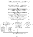
- Fig. 1 is a flowchart of a method for collision avoidance control of automatic lane change provided in Embodiment One of the present invention.
- the embodiment is applicable to the situation of determining a collision avoidance strategy in response to a vehicle encountering a lane change abnormality during automatic lane change.
- the method may be executed by an apparatus for collision avoidance control of automatic lane change, the apparatus for collision avoidance control of automatic lane change may be implemented by software and/or hardware, and the apparatus for collision avoidance control of automatic lane change may be configured on a computing device.
- the method includes the following steps.
- step S101 driving parameters of a current vehicle, driving parameters of at least one target vehicle, and road information are acquired in response to the current vehicle executing a lane change operation.
- the driving parameters of the current vehicle may be understood as feature values used for indicating a driving state of the current vehicle at a current moment.
- the driving parameters of the current vehicle may include a longitudinal velocity of the current vehicle, a longitudinal acceleration of the current vehicle, a lateral velocity of the current vehicle, a lateral acceleration of the current vehicle, a position of the current vehicle, etc.
- the driving parameters of the current vehicle may be acquired by an electronic stability program (ESP) and multiple cameras and radars which are mounted on a vehicle body.
- ESP electronic stability program
- At least one target vehicle may be understood as at least one vehicle that may pose a collision threat to the current vehicle during automatic lane change.
- the at least one target vehicle may include at least one vehicle before and behind the current vehicle in an original lane in response to the current vehicle not changing a lane and at least one vehicle before and behind the current vehicle in a target lane that the current vehicle is expected to after lane change.
- the driving parameters of the at least one target vehicle may be understood as feature values used for indicating a driving state of the at least one target vehicle at a current moment.
- the driving parameters of the target vehicle may include a longitudinal velocity of the at least one target vehicle, a longitudinal acceleration of the at least one target vehicle, a lateral velocity of the at least one target vehicle, a lateral acceleration of the at least one target vehicle, a position of the at least one target vehicle, etc.
- the driving parameters of the at least one target vehicle may be acquired by multiple cameras and radars which are mounted on the vehicle body of the current vehicle.
- the road information may be understood as road surface information of a lane where the current vehicle is located and the target lane that the current vehicle is expected to enter after lane change, which is acquired by the current vehicle.
- the road information may include lane line information of the original lane and the target lane.
- the road information may be acquired by multiple cameras that are mounted on the vehicle body of the current vehicle.
- the lateral and longitudinal velocities and the lateral and longitudinal accelerations of the current vehicle are acquired by the ESP of the current vehicle.
- the position of the current vehicle is determined by multiple cameras and radars which are mounted on the vehicle body, and the acquired parameters are used as the driving parameters of the current vehicle.
- lateral velocities, longitudinal velocities, lateral accelerations, longitudinal accelerations, and positions of target vehicles that are located before and behind the current vehicle in a lane where the current vehicle is located and before and behind the current vehicle in the target lane are acquired by multiple cameras and radars which are mounted on the vehicle body of the current vehicle.
- the acquired parameters are used as the driving parameters of the target vehicle.
- the lane line information of the lane where the current vehicle is located and the target lane that the current vehicle is expected to after lane change is acquired by multiple cameras that are mounted on the vehicle body of the current vehicle, and the information is used as the road information.
- step S102 a travel collision safety detection time period, a return collision safety detection time period, and lane change virtual action lines are determined according to the driving parameters of the current vehicle, the driving parameters of the at least one target vehicle, and the road information.
- the travel collision safety detection time period may be understood as the shortest time period of a collision between the current vehicle and the at least one target vehicle in the target lane in response to the current vehicle executing the lane change operation with a current travel velocity unchanged.
- the return collision safety detection time period may be understood as the shortest time period of a collision between the current vehicle and at least one target vehicle in the original lane in response to the current vehicle returning from a current position to the original lane with the current travel velocity of the current vehicle unchanged.
- the lane change virtual action lines may be understood as virtual action lines on two sides of an overlapping lane line, which are determined according to a position of the overlapping lane line (namely a lane line shared by the target lane and the original lane) of the target lane and the original lane, and may be configured to assist in determining the current position of the current vehicle and danger of travel and return.
- the collision safety detection time period of each target vehicle and the current vehicle is computed according to the longitudinal velocity and the longitudinal acceleration of the current vehicle, the longitudinal velocity and the longitudinal acceleration of this target vehicle, as well as a longitudinal relative distance between this target vehicle and the current vehicle.
- the minimum collision safety detection time period is determined from collision safety detection time periods corresponding to all target vehicles in the target lane, and the minimum collision safety detection time period is determined as the travel collision safety detection time period.
- the minimum collision safety detection time period is determined from collision safety detection time periods corresponding to all target vehicles in the original lane of the current vehicle, and the minimum collision safety detection time period is determined as the return collision safety detection time period.
- the lane line shifts to an original lane side where a vehicle is located by a first preset distance so as to determine a virtual action line as a return allowing action line
- the lane line shifts to a target lane side that the current vehicle is expected to after lane change by a second preset distance so as to determine a virtual action line as a return prohibiting action line
- the return allowing action line and the return prohibiting action line are used as the lane change virtual action lines.
- step S103 in response to the lane change abnormality being detected, a collision avoidance strategy is determined according to a positional relation between the current vehicle and the lane change virtual action lines, the travel collision safety detection time period, and the return collision safety detection time period, and the current vehicle is controlled to execute the collision avoidance strategy.
- the lane change abnormality may be understood as a situation that the current vehicle cannot continue changing a lane according to a pre-computed lane change track.
- the lane change abnormality may include a lane change stop actively triggered by a driver of the current vehicle, a lane change stop in response to the current vehicle detecting a collision risk during lane change, a lane change stop caused by some conditions of the current vehicle, etc.
- the collision avoidance strategy may be understood as planning of a driving strategy to avoid a collision for the current vehicle during lane change, and may include the return strategy of returning to the original lane and the travel strategy of continuing changing a lane for driving.
- a relative positional relation between the current vehicle and the original lane as well as the target lane during lane-changing driving is determined, according to a relative positional relation between the current position of the current vehicle and the lane change virtual action lines.
- collision risks under a current positional relation are determined, according to the travel collision safety detection time period and the return collision safety detection time period, to obtain a determination result.
- a driving strategy with a low collision risk is selected, according to the determination result, as a collision avoidance strategy, and the current vehicle is controlled to execute the collision avoidance strategy so as to travel in a manner with a low risk.
- the driving parameters of the current vehicle, the driving parameters of the at least one target vehicle, and the road information are acquired in response to the current vehicle executing the lane change operation.
- the travel collision safety detection time period, the return collision safety detection time period, and the lane change virtual action lines are determined according to the driving parameters of the current vehicle, the driving parameters of the at least one target vehicle, and the road information.
- the collision avoidance strategy is determined according to the positional relation between the current vehicle and the lane change virtual action lines, the travel collision safety detection time period, and the return collision safety detection time period to control the current vehicle to execute the collision avoidance strategy.
- the at least one target vehicle includes at least one vehicle before and behind the current vehicle in the original lane and at least one vehicle before and behind the current vehicle in the target lane.
- the travel collision safety detection time period, the return collision safety detection time period, and the lane change virtual action lines are determined according to the driving parameters of the current vehicle, the driving parameters of the at least one target vehicle, and the road information.
- the collision risks for the current vehicle continuing changing a lane and returning to the original lane may be determined according to the position of the current vehicle in the lane at the current moment, the travel collision safety detection time period and the return collision safety detection time period to obtain a determination result.
- a solution with a lowest risk is selected as the collision avoidance strategy, so that the current vehicle travels according to the collision avoidance strategy.
- the method solves a problem in the related art that it is difficult to determine the collision avoidance strategy with the lowest risk in response to a vehicle encountering the lane change abnormality during automatic lane change, decreases a possibility of collisions in response to the vehicle encountering an automatic lane change abnormality, avoids responsibility of the vehicle to the maximum extent in response to a collision being inevitable, reduces severity of a collision in response to collision being inevitable, and improves driving safety of the vehicle.
- Fig. 2 is a flowchart of a method for control of automatic lane change provided in Embodiment Two of the present invention.
- the technical solution of the embodiment is described on the basis of the above technical solution, and the method includes the steps as follows.
- step S201 driving parameters of a current vehicle, driving parameters of at least one target vehicle, and road information are acquired in response to the current vehicle executing a lane change operation.
- a collision safety detection time period between each target vehicle and the current vehicle is determined according to a longitudinal velocity of the current vehicle, a longitudinal acceleration of the current vehicle, a longitudinal velocity of each target vehicle, a longitudinal acceleration of each target vehicle, and a longitudinal relative distance between each target vehicle and the current vehicle.
- the longitudinal velocity of the current vehicle is indicated as Vsv
- the longitudinal acceleration of the current vehicle is indicated as a SV
- the longitudinal velocity of the target vehicle is indicated as V TV
- the longitudinal acceleration of the target vehicle is indicated as a TV
- the longitudinal relative distance is indicated as X c
- ETTC longitudinal ⁇ V TV ⁇ V SV ⁇ V TV ⁇ V SV 2 ⁇ 2 ⁇ a TV ⁇ a SV ⁇ X c a TV ⁇ a SV
- step S203 the minimum collision safety detection time period is determined from collision safety detection time periods of all target vehicles in a target lane and the current vehicle and the minimum collision safety detection time period is determined as the travel collision safety detection time period.
- Collision safety detection time period corresponding to multiple target vehicles that possibly collide with the current vehicle in the target lane is acquired, the collision safety detection time periods indicate collision time periods of the current vehicle with the multiple target vehicles that possibly collide with the current vehicle in response to the current vehicle changing a lane at a current velocity, the minimum collision safety detection time period is selected from the collision safety detection time periods and the minimum collision safety detection time period is determined as the travel collision safety detection time period, which indicates a collision risk that the current vehicle has in response to changing a lane and traveling to the target lane at a current moment.
- step S204 the minimum collision safety detection time period is determined from collision safety detection time periods of all target vehicles in an original lane and the current vehicle is determined as return collision safety detection time period.
- Collision safety detection time periods corresponding to multiple target vehicles that possibly collide with the current vehicle in the original lane where the current vehicle is located in response to the current vehicle not changing a lane is acquired, the collision safety detection time periods indicate collision time periods of the current vehicle with the multiple target vehicles that possibly collide with the current vehicle in response to the current vehicle returning to the original lane at the current velocity, the minimum collision safety detection time period is selected from the acquired collision safety detection time periods, and the minimum collision safety detection time period is determined as the return collision safety detection time period, which indicates a collision risk that the current vehicle has in response to giving up changing a lane and returning to the original lane at the current moment.
- step S205 lane change virtual action lines are determined according to a position of the current vehicle and a position of a lane line shared by the target lane and the original lane.
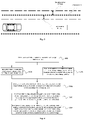
- Fig. 3 is a diagram of an example of a lane change virtual action lines provided in an embodiment of the present invention.
- a vehicle coordinate system is created by taking a vehicle center of the current vehicle as an origin, Y as a lateral distance, leftward as positive, X as a longitudinal distance and forward as positive. It may be seen from Fig.
- the return allowing action line and the return prohibiting action line are used as the lane change virtual action lines.
- step S206 a positional relation between the current vehicle and each lane change virtual action line is determined in response to a lane change abnormality being detected.
- the lane change abnormality may include a lane change stop actively triggered by a driver of the current vehicle, a lane change stop in response to the current vehicle detecting a collision risk during lane change, a lane change stop caused by conditions of the current vehicle, etc.
- the lane change stop actively triggered by the driver may include: actively turning off a turn light by a driver, reversely turning a steering wheel by the driver, actively decelerating to a lane change critical velocity or below by the driver, actively accelerating to the lane change critical velocity or above by the driver, etc..
- the lane change stop in response to the collision risk being detected may include: sudden rapid deceleration of vehicles before the target lane, sudden rapid acceleration of vehicles behind the target lane, sudden cutting of a vehicle on a third lane into the lane (which is the lane where the current lane is located), sudden rapid deceleration of vehicles before the lane, sudden rapid acceleration of vehicles behind the lane, etc..
- the lane change stop caused by the conditions of the current vehicle may include: following a preceding vehicle and decelerating to a critical velocity or below by the current vehicle, following the preceding vehicle and accelerating to the critical velocity or above by the current vehicle, etc.
- the positional relation between the current vehicle and each of the lane change virtual action lines is determined according to cameras mounted on a vehicle body, so as to determine a collision risk of travel and return of the current vehicle according to the positional relation.
- the positional relation between the current vehicle and each of the lane change virtual action lines may be divided into: 1) a front wheel of the current vehicle does not pass the return allowing action line, that is, lane change of the current vehicle is just started and the current vehicle is not deviated from the original lane; 2) the front wheel of the current vehicle is located between the return allowing action line and the return prohibiting action line, that is, the lane change of the current vehicle is executed for a certain time period, and the current vehicle is in a process of passing the lane line from the original lane to the target lane; and 3) a rear wheel of the current vehicle passes the return prohibiting action line, that is, the lane change of the current vehicle comes to an end, and a whole vehicle basically completely enters the target lane.
- step S207 whether the travel collision safety detection time period is less than a first preset threshold is determined in response to a front wheel of the current vehicle not passing the return allowing action line.
- the current vehicle does not leave the original lane.
- the travel collision safety detection time period is compared with the first preset threshold.
- the first preset threshold is time data set according to an empirical value. In response to the travel collision safety detection time period being less than the first preset threshold, it is considered that a probability of a collision of the current vehicle during longitudinal traveling into the target lane is high.
- the first preset threshold may be set in advance. Different empirical values may be set for different vehicles, which are not limited by the embodiment of the present invention.
- step S208 the collision avoidance strategy is determined as a return strategy.
- step S209 the collision avoidance strategy is determined as a travel strategy.
- step S210 in response to the front wheel of the current vehicle being located between the return allowing action line and the return prohibiting action line, the collision avoidance strategy is determined according to a magnitude relation among the travel collision safety detection time period, the return collision safety detection time period, the first preset threshold and a second preset threshold.
- the position of the current vehicle is on the lane line shared by the target lane and the original lane and is in a state of passing the lane line.
- a vehicle in the original lane and at least one vehicle in the target lane possibly cause great danger to the current vehicle, so it is necessary to comprehensively consider the travel collision safety detection time period and the return collision safety detection time period, so as to determine the collision avoidance strategy according to the magnitude relation among the travel collision safety detection time period, the return collision safety detection time period, the first preset threshold and the second preset threshold.
- the second preset threshold and the first preset threshold are similar and are time data set according to the empirical value. In response to the return collision safety detection time period being less than the second preset threshold, it is considered that a probability of a collision during longitudinal traveling in returning to the original lane is high.
- the second preset threshold may be set in advance. Different empirical values may be set for different vehicles, which are not limited by the embodiment of the present invention.
- the operation that the collision avoidance strategy is determined according to the magnitude relation among the travel collision safety detection time period, the return collision safety detection time period, the first preset threshold and the second preset threshold includes the steps as follows.
- step S2101 in response to the travel collision safety detection time period being greater than the first preset threshold, the collision avoidance strategy is determined as a driving strategy; and in response to the travel collision safety detection time period being less than or equal to the first preset threshold, whether the return collision safety detection time period is less than the second preset threshold is determined.
- the collision avoidance strategy may be determined as the driving strategy for continuous lane change.
- the travel collision safety detection time being less than the first preset threshold, it may be considered that there is a large possibility of a collision under the condition that the current vehicle continues changing a lane to the target lane.
- step S2102 in response to the return collision safety detection time period being less than the second preset threshold, the current vehicle is controlled to travel on a lane line and give an alarm.
- the current vehicle In response to the return collision safety detection time being less than the second preset threshold, it may be considered that there is a large possibility of a collision under the condition that the current vehicle returns to the original lane. Meanwhile, there is a large possibility of a collision in response to the current vehicle changing a lane to the target lane. In this case, it is difficult to select an appropriate collision avoidance strategy to make automatic lane change continue, which requires a driver to intervene and select an appropriate driving mode to reduce a possibility of a collision. To avoid a lateral and longitudinal runaway of the current vehicle before the driver takes charge of the current vehicle, the current vehicle is controlled to travel across a line along the overlapping lane line shared by the original lane and the target lane, and give an alarm by turning on double flashing warning lights. Optionally, exiting may be executed after traveling for 2 second across a line, or the driver may manually exit a mode of traveling across a line after taking charge of the current vehicle.
- the operation that the current vehicle is controlled to travel across a line includes the following steps. According to a lateral distance between a center line of the current vehicle and a closest lane line, the current vehicle is controlled to travel along a track, with the lateral distance smaller than a preset deviation.
- the position of the current vehicle is on a lane line adjacent to the target lane and the original lane, so the closest lane line is a shared lane line.
- a lateral distance between a center of the current vehicle and the lane line may be understood as a lateral deviation between the current vehicle and the lane line.
- the current vehicle is controlled to travel along the lane line according to the track having the lateral distance smaller than the preset deviation, so as to travel on the shared lane line.
- step S2103 in response to the return collision safety detection time being greater than the second preset threshold, the collision avoidance strategy is determined according to the travel collision safety detection time period and the return collision safety detection time period.
- the collision avoidance strategy is determined as the travel strategy.
- the possibility of the collision under the condition that the current vehicle continues changing a lane to the target lane is greater than the possibility of the collision in response to the current vehicle returning to the original lane in the current driving state, so the collision avoidance strategy is determined as the return strategy.
- a "safety responsibility model” may further be created.
- ETTC(mov) travel collision safety detection time period
- ETTC(ret) return collision safety detection time period
- ETTC is a collision time period of realizing a final lane change safety state
- ⁇ is a lane change travel risk factor
- ⁇ is a lane change return risk factor.
- ETTC may be understood as the collision time period in response to a vehicle changing a lane at the current velocity and has a closest distance from a vehicle in the target lane as a safe distance D safe after completing lane change, may be computed according to a longitudinal distance between the current vehicle and the target vehicle, the safe distance and a vehicle driving velocity, and may be considered as a set threshold for determining a lane change risk.
- the travel collision safety detection time period and the return collision safety detection time period are normalized by means of risk factors. It may be understood that, in response to ETTC(mov)>ETTC(ret), a risk factor (namely weight factor) in the corresponding safety responsibility model satisfies ⁇ ⁇ ⁇ , which indicates that in this case, a lane change travel risk is less than a lane change return risk, and it may be determined that it is safer for the current vehicle to continue changing a lane.
- a risk factor (namely weight factor) in the corresponding safety responsibility model satisfies ⁇ > ⁇ , which indicates that in this case, a lane change travel risk is greater than a lane change return risk, and it may be determined that it is safer for the current vehicle to return to the original lane.
- step S211 the collision avoidance strategy is determined as the travel strategy in response to the rear wheel of the current vehicle passing the return prohibiting action line.
- the collision avoidance strategy is determined as the travel strategy.
- the current vehicle In response to a target vehicle before the current vehicle being detected to have a sudden collision danger, the current vehicle is controlled to be subjected to following control after the target vehicle decelerates. In response to deceleration of the target vehicle causing the current vehicle to trigger an emergency braking function, the current vehicle exits automatic lane change and gives an alarm, and then the driver takes charge of the current vehicle.
- step S212 the current vehicle is controlled to execute the collision avoidance strategy.
- a return track is planned for the current vehicle, and the current vehicle is controlled to return to the original lane along the return track.
- the collision avoidance strategy is the travel strategy
- a new lane change track is planned for the current vehicle, and the current vehicle is controlled to continue changing a lane to the target lane and travel along the new lane change track.
- a lane change state is determined according to the lane change virtual action lines determined by means of the lane line shared by the original lane and the target lane and the position of the current vehicle.
- possibilities of collisions under the conditions that the current vehicle continues changing a lane and returns to the original lane are determined by means of the travel collision safety detection time period and the return collision safety detection time period, the driving strategy with a low collision probability is selected as the collision avoidance strategy, and the current vehicle is controlled to travel according to the collision avoidance strategy.
- the current vehicle exits automatic lane change control in time, then the driver takes charge of the current vehicle, and the current vehicle is kept traveling across a line before being taken charge of, so as to minimize a possibility of a collision and improve driving safety of the current vehicle.
- Fig. 4 is a flowchart of a method for collision avoidance control of automatic lane change provided in Embodiment Three of the present invention.
- the technical solution of the embodiment is described on the basis of the above technical solution.
- the method includes the steps as follows.
- step S301 whether a current vehicle satisfies an automatic lane change condition is determined.
- the automatic lane change condition includes that lateral movement risk collision time period is greater than a third preset threshold, and the travel collision safety detection time period of the current vehicle is greater than a first preset threshold.
- whether there is a vehicle having a lateral overlap with the current vehicle is determined by means of radars mounted on a vehicle body.
- the vehicle is taken as the target vehicle, a lateral velocity and a lateral acceleration of the vehicle as well as a lateral relative distance between the vehicle and the current vehicle are acquired, and a lateral velocity and a lateral acceleration of the current vehicle are acquired.
- the lateral movement risk collision time period is determined according to the acquired parameters.
- V TV ′ may be indicated as a lateral velocity of a target vehicle
- V SV ′ may be indicated as the lateral velocity of the current vehicle
- a TV ′ may be indicated as a lateral acceleration of the target vehicle
- a SV ′ may be indicated as the lateral acceleration of the current vehicle
- X c ′ may be indicated as a lateral distance between the target vehicle and the current vehicle.
- step S302 In response to the current vehicle satisfying the automatic lane change condition, step S302 is executed, and in response to the current vehicle not meeting the automatic lane change condition, step S303 is executed.
- the third preset threshold is time data set according to an empirical value, which is not limited by the embodiment of the present invention.
- step S302 the current vehicle is controlled to automatically change a lane according to a lane change track.
- the operation that the lane change track is determined includes the following steps. A velocity, a yaw velocity, a lateral distance between a center of a vehicle head and a lane line shared by the target lane and an original lane, and an angle of the current vehicle relative to a center line of the target lane at a current moment of the current vehicle are acquired. The above parameters are substituted into a lane line equation so as to obtain the lane change track, and the current vehicle is controlled to enter an automatic lane change process according to the lane change track.
- a vehicle coordinate system is created by taking a vehicle center of the current vehicle as an origin, Y as a lateral distance, leftward as positive, X as a longitudinal distance and forward as positive, ⁇ s is the yaw velocity of the current vehicle, V x is the velocity at the current moment of the current vehicle, ⁇ is the angle of the current vehicle relative to the center line of the target lane, and Co is the lateral distance between the center of the vehicle head and the lane line shared with the original lane in the target lane.
- step S303 the current vehicle is controlled to decelerate and update the lane change track to further determine whether the current vehicle satisfies the automatic lane change condition.
- the current vehicle has at least one of two problems that there is a vehicle in a lateral direction of the current vehicle and a vehicle velocity of the current vehicle is too high.
- the existence of a vehicle in the lateral direction of the current vehicle cannot be controlled by the current vehicle.
- the current vehicle is controlled to decelerate, the lane change track is computed again according to driving parameters of the current vehicle after deceleration to update the lane change track. Whether current driving parameters of the current vehicle meet the automatic lane change condition is determined.
- the current vehicle In response to the current vehicle satisfying the automatic lane change condition, the current vehicle is controlled to automatically change a lane according to the updated lane change track, and in response to the current vehicle not meeting the automatic lane change condition, the step is executed again so as to update the lane change track.
- step S304 driving parameters of the current vehicle, driving parameters of at least one target vehicle, and road information are acquired in response to the current vehicle executing a lane change operation.
- step S305 the travel collision safety detection time period, the return collision safety detection time period, and lane change virtual action lines are determined according to the driving parameters of the current vehicle, the driving parameters of the at least one target vehicle, and the road information.
- step S306 in response to a lane change abnormality being detected, a collision avoidance strategy is determined according to a positional relation between the current vehicle and each lane change virtual action line, the travel collision safety detection time period, and the return collision safety detection time period to control the current vehicle to execute the collision avoidance strategy.
- the lateral movement risk collision time period of the target vehicle having a lateral overlap with the current vehicle and the travel collision safety detection time period of the target vehicle in the target lane are computed before the current vehicle enters an automatic lane change mode.
- the lane change track is determined according to the driving parameters of the current vehicle at the current moment.
- the current vehicle is enabled to automatically change a lane and travel according to the lane change track, thereby reducing a possibility of a collision in response to the current vehicle automatically changing a lane and improving driving safety of the current vehicle.
- Fig. 5 is a structural schematic diagram of an apparatus for collision avoidance control of automatic lane change provided in Embodiment Four of the present invention.
- the apparatus for collision avoidance control of automatic lane change includes: an information acquisition module 41, an information determination module 42 and a collision avoidance strategy determination module 43.
- the information acquisition module 41 is configured to acquire driving parameters of a current vehicle, driving parameters of at least one target vehicle, and road information in response to the current vehicle executing a lane change operation.
- the information determination module 42 is configured to determine a travel collision safety detection time period, a return collision safety detection time period, and lane change virtual action lines according to the driving parameters of the current vehicle, the driving parameters of the at least one target vehicle, and the road information.
- the collision avoidance strategy determination module 43 is configured to determine, in response to a lane change abnormality being detected, a collision avoidance strategy according to a positional relation between the current vehicle and the lane change virtual action lines, the travel collision safety detection time period, and the return collision safety detection time period to control the current vehicle to execute the collision avoidance strategy.
- a problem that it is difficult to determine the collision avoidance strategy with a lowest risk in response to the current vehicle encountering the lane change abnormality during automatic lane change is solved, a possibility of a collision in response to the current vehicle encountering an automatic lane change abnormality is decreased, severity of a collision in response to a collision being inevitable is reduced, and driving safety of the current vehicle is improved.
- the at least one target vehicle includes at least one vehicle before and behind the current vehicle in an original lane and at least one vehicle before and behind the current vehicle in a target lane.
- the driving parameters of the current vehicle at least include a longitudinal velocity of the current vehicle, a longitudinal acceleration of the current vehicle and a position of the current vehicle.
- the driving parameters of the at least one target vehicle at least include a longitudinal velocity of each target vehicle, a longitudinal acceleration of each target vehicle and a position of each target vehicle.
- the lane change virtual action lines include a return allowing action line and a return prohibiting action line.
- the information determination module 42 includes: a safety detection time determination unit configured to determine the collision safety detection time period of each target vehicle and the current vehicle according to the longitudinal velocity of the current vehicle, the longitudinal acceleration of the current vehicle, the longitudinal velocity of each target vehicle, the longitudinal acceleration of each target vehicle, a longitudinal relative distance between each target vehicle and the current vehicle; and a virtual action line determination unit configured to determine the lane change virtual action lines according to the position of the current vehicle and a position of a lane line shared by the target lane and the original lane.
- the safety detection time determination unit is configured to determine the minimum collision safety detection time period from collision safety detection time periods of all target vehicles in the target lane and the current vehicle as the travel collision safety detection time period; and to determine the minimum collision safety detection time period from collision safety detection time periods of all target vehicles in the original lane and the current vehicle as the return collision safety detection time period.
- the collision avoidance strategy determination module 43 is configured to: determine whether the travel collision safety detection time period is less than a first preset threshold in response to a front wheel of the current vehicle not passing the return allowing action line, determine the collision avoidance strategy as a return strategy in response to the travel collision safety detection time period being less than the first preset threshold, and determine the collision avoidance strategy as a travel strategy in response to the travel collision safety detection time period being greater than or equal to the first preset threshold; determine, in response to the front wheel of the current vehicle being located between the return allowing action line and the return prohibiting action line, the collision avoidance strategy according to a magnitude relation among the travel collision safety detection time period, the return collision safety detection time period, the first preset threshold and a second preset threshold; and determine the collision avoidance strategy as the travel strategy in response to a rear wheel of the current vehicle passing the return prohibiting action line.
- the determining the collision avoidance strategy according to a magnitude relation among the travel collision safety detection time period, the return collision safety detection time period, the first preset threshold and a second preset threshold includes: determining the collision avoidance strategy as the travel strategy in response to the travel collision safety detection time period being greater than the first preset threshold; determining whether the return collision safety detection time period is less than the second preset threshold in response to the travel collision safety detection time period being less than or equal to the first preset threshold, and controlling the current vehicle to travel across a line and give an alarm in response to the return collision safety detection time period being less than the second preset threshold; and determining, in response to the return collision safety detection time period being greater than or equal to the second preset threshold, the collision avoidance strategy according to the travel collision safety detection time period and the return collision safety detection time period.
- An operation of determining the collision avoidance strategy according to the travel collision safety detection time period and the return collision safety detection time period includes the following steps.
- the collision avoidance strategy is determined as the travel strategy in response to the travel collision safety detection time period being greater than the return collision safety detection time period.
- the collision avoidance strategy is determined as the return strategy in response to the travel collision safety detection time period being less than the return collision safety detection time period.
- the apparatus further includes: a lane change track determination module configured to determine whether the current vehicle satisfies an automatic lane change condition; control the current vehicle to automatically change a lane according to a lane change track in response to the current vehicle satisfying the automatic lane change condition; and control the current vehicle to decelerate and update the lane change track in response to the current vehicle not meeting the automatic lane change condition to further determine whether the current vehicle satisfies the automatic lane change condition.
- the automatic lane change condition includes a lateral movement risk collision time period being greater than a third preset threshold, and the travel collision safety detection time period of the current vehicle being greater than the first preset threshold.
- the operation that the lane change track is determined includes the following steps.
- a velocity, a yaw velocity, a lateral distance between a center of a vehicle head and a lane line shared by the target lane and the original lane, and an angle of the current vehicle relative to a center line of the target lane at a current moment of the current vehicle are acquired.
- the velocity, the yaw velocity, the lateral distance between the center of the vehicle head and the lane line shared with the original lane in the target lane, and the angle of the current vehicle relative to the center line of the target lane at the current moment of the current vehicle are substituted into a lane line equation so as to determine the lane change track.
- the apparatus for collision avoidance control of automatic lane change provided in the embodiment of the present invention may execute the method for collision avoidance control of automatic lane change provided in any embodiment of the present invention, and has corresponding functional modules upon execution of the method.
- Fig. 6 is a structural schematic diagram of a vehicle provided in Embodiment Five of the present invention.
- the vehicle includes a controller 51, a storage apparatus 52, an input device 53 and an output device 54.
- the controller 51, the storage apparatus 52, the input device 53 and the output device 54 in the vehicle may be connected by means of buses or in other ways. Bus connection is taken as an example in Fig. 6 .
- the storage apparatus 52 may be set as a storage software program, a computer executable program and a module, such as a program instruction/module corresponding to the method for collision avoidance control of automatic lane change in the embodiments of the present invention (such as an information acquisition module 41, an information determination module 42 and a collision avoidance strategy determination module 43).
- the controller 51 executes various functional applications of the vehicle and data processing by traveling a software program, an instruction and a module stored in the storage apparatus 52, thereby implementing the method for collision avoidance control of automatic lane change.
- the storage apparatus 52 may mainly include a program storage area and a data storage area, where the program storage area may store an operating system and an application program required for at least one function; and the data storage area may store data, etc. created according to usage of a terminal.
- the storage apparatus 52 may include a high-velocity random access memory, and may further include a non-volatile memory, for example, at least one magnetic disk memory device, a flash memory device, or other non-volatile solid-state memory devices.
- the storage apparatus 52 may include a memory remotely set with respect to the controller 51, and the remote memories may be connected with the vehicle by means of a network. Examples of the networks include, but are not limited to, the Internet, enterprise intranets, local area networks, mobile communication networks, and combinations thereof.
- the input device 53 may be set to receive input digital or character information and generate key signal input related to user settings and function control of the vehicle.
- the output device 54 may include display devices such as a display screen.
- Embodiment Six of the present invention further provides a storage medium including at least one computer executable instruction, and the at least one computer executable instruction is configured to execute a method for collision avoidance control of automatic lane change in response to being executed by a computer processor.
- the method includes the following steps that: driving parameters of a current vehicle, driving parameters of at least one target vehicle, and road information are acquired in response to the current vehicle executing a lane change operation; a travel collision safety detection time period, a return collision safety detection time period, and lane change virtual action lines are determined according to the driving parameters of the current vehicle, the driving parameters of the at least one target vehicle, and the road information; and in response to a lane change abnormality being detected, a collision avoidance strategy is determined according to a positional relation between the current vehicle and the lane change virtual action lines, the travel collision safety detection time period, and the return collision safety detection time period to control the current vehicle to execute the collision avoidance strategy.
- the at least one target vehicle includes at least one vehicle before and behind the current vehicle in an original
- the computer executable instruction is not limited by method operations described above, and may further execute related operations in the method for collision avoidance control of automatic lane change provided in any embodiment of the present invention.
- the present invention may be implemented by means of software and general hardware, and may be certainly implemented by hardware. Based on such understanding, the technical solution of the present invention may be embodied in the form of software products in essence or in part that contributes to related technologies, the computer software products may be stored in the computer readable storage medium, such as a floppy disk, a read-only memory (ROM), a random access memory (RAM), a flash memory, a hard disk and an optical disk of a computer, and several instructions are included to make a computer device (which may be a personal computer, a server, a network device, etc.) execute the method described in multiple embodiments of the present invention.
- a computer device which may be a personal computer, a server, a network device, etc.
Landscapes
- Engineering & Computer Science (AREA)
- Automation & Control Theory (AREA)
- Transportation (AREA)
- Mechanical Engineering (AREA)
- Human Computer Interaction (AREA)
- Physics & Mathematics (AREA)
- Mathematical Physics (AREA)
- Traffic Control Systems (AREA)
Abstract
Description
- The present invention claims the priority of
Chinese Patent Application No. 202010591875.9, filed to the Chinese Patent Office on June 24, 2020 - Embodiments of the present invention relate to the technical field of autonomous driving control, and in particular to a method and apparatus for collision avoidance control of automatic lane change, a vehicle, and a storage medium.
- The development of an autonomous driving function of a vehicle is in full swing. With the autonomous driving function, a driver can be liberated from driving with hands, feet and eyes looking ahead. Once a navigation destination is set, the driver even does not have to take charge of the vehicle. An autonomous vehicle has multiple autonomous decision-making and control tasks, including autonomous control of centering, autonomous control of lane changing, autonomous navigation path planning, etc. It is necessary to take essential measures for various abnormal working conditions during autonomous driving to minimize risks, so as to ensure safety of autonomous driving.
- For active and safe collision prevention in automatic vehicle lane change, firstly whether a vehicle can change a lane is determined by detecting whether there is a target affecting lane change in an adjacent lane. For example, with a collision avoidance threshold of lane change danger set, in response to a distance between the target in the adjacent lane and the present vehicle being detected to be less than the threshold, the vehicle stops changing the lane and continues traveling in an original lane.
- However, during automatic lane change, information such as an operating state of a driver and a state and a posture of a vehicle tends to affect lane change decision-making. Further, during lane change, in response to the present vehicle directly stopping changing the lane and returns to the original lane, it also possibly collides with another vehicle in the original lane, resulting in greater danger.
- At least some embodiments of the present invention provide a method and apparatus for collision avoidance control of automatic lane change, a vehicle and a storage medium, so as at least to realize collision avoidance control of a vehicle when the vehicle encounters a lane change abnormality during lane change, decrease a possibility of a collision when the vehicle encounters an automatic lane change abnormality, reduce severity of a collision when a collision is inevitable, and improve driving safety of the vehicle.
- An embodiment of the present invention provides a method for collision avoidance control of automatic lane change. The method includes: acquiring driving parameters of a current vehicle, driving parameters of at least one target vehicle, and road information in response to the current vehicle executing a lane change operation; determining a travel collision safety detection time period, a return collision safety detection time period, and lane change virtual action lines according to the driving parameters of the current vehicle, the driving parameters of the at least one target vehicle, and the road information; and determining, in response to a lane change abnormality being detected, a collision avoidance strategy according to a positional relation between the current vehicle and the lane change virtual action lines, the travel collision safety detection time period, and the return collision safety detection time period to control the current vehicle to execute the collision avoidance strategy, and the at least one target vehicle includes at least one vehicle before and behind the current vehicle in an original lane and at least one vehicle before and behind the current vehicle in a target lane.
- Another embodiment of the present invention further provides an apparatus for collision avoidance control of automatic lane change. The apparatus for collision avoidance control of automatic lane change includes: an information acquisition module configured to acquire driving parameters of a current vehicle, driving parameters of at least one target vehicle, and road information in response to the current vehicle executing a lane change operation; an information determination module configured to determine a travel collision safety detection time period, a return collision safety detection time period, and lane change virtual action lines according to the driving parameters of the current vehicle, the driving parameters of the at least one target vehicle, and the road information; and a collision avoidance strategy determination module configured to determine, in response to a lane change abnormality being detected, a collision avoidance strategy according to a positional relation between the current vehicle and the lane change virtual action lines, the travel collision safety detection time period, and the return collision safety detection time period to control the current vehicle to execute the collision avoidance strategy, and the at least one target vehicle includes at least one vehicle before and behind the current vehicle in an original lane and at least one vehicle before and behind the current vehicle in a target lane.
- Another embodiment of the present invention further provides a vehicle. The vehicle includes: at least one controller; and a storage apparatus configured to store at least one program, and at least one controller implement the method for collision avoidance control of automatic lane change provided in any one of the embodiments of the present invention in response to executing at least one program.
- Another embodiment of the present invention further provides a storage medium including at least one computer executable instruction, where the computer executable instruction is configured to execute the method for collision avoidance control of automatic lane change provided in any one of the embodiments of the present invention in response to being executed by a computer processor.
-
-
Fig. 1 is a flowchart of a method for collision avoidance control of automatic lane change in Embodiment One of the present invention. -
Fig. 2 is a flowchart of a method for collision avoidance control of automatic lane change in Embodiment Two of the present invention. -
Fig. 3 is a diagram of an example of lane change virtual action lines in Embodiment Two of the present invention. -
Fig. 4 is a flowchart of a method for collision avoidance control of automatic lane change in Embodiment Three of the present invention. -
Fig. 5 is a structural schematic diagram of an apparatus for collision avoidance control of automatic lane change in Embodiment Four of the present invention. -
Fig. 6 is a structural schematic diagram of a vehicle in Embodiment Five of the present invention. - The present invention will be described below with reference to accompanying drawings and in conjunction with embodiments. It may be understood that embodiments described herein are used for explaining the present invention, but not limit the present invention. Moreover, it should be noted that, for convenience of description, some rather than all of structures related to the present invention are shown in the accompanying drawings.
-
Fig. 1 is a flowchart of a method for collision avoidance control of automatic lane change provided in Embodiment One of the present invention. The embodiment is applicable to the situation of determining a collision avoidance strategy in response to a vehicle encountering a lane change abnormality during automatic lane change. The method may be executed by an apparatus for collision avoidance control of automatic lane change, the apparatus for collision avoidance control of automatic lane change may be implemented by software and/or hardware, and the apparatus for collision avoidance control of automatic lane change may be configured on a computing device. The method includes the following steps. - In step S101, driving parameters of a current vehicle, driving parameters of at least one target vehicle, and road information are acquired in response to the current vehicle executing a lane change operation.
- The driving parameters of the current vehicle may be understood as feature values used for indicating a driving state of the current vehicle at a current moment. Optionally, the driving parameters of the current vehicle may include a longitudinal velocity of the current vehicle, a longitudinal acceleration of the current vehicle, a lateral velocity of the current vehicle, a lateral acceleration of the current vehicle, a position of the current vehicle, etc. The driving parameters of the current vehicle may be acquired by an electronic stability program (ESP) and multiple cameras and radars which are mounted on a vehicle body.
- At least one target vehicle may be understood as at least one vehicle that may pose a collision threat to the current vehicle during automatic lane change. Optionally, the at least one target vehicle may include at least one vehicle before and behind the current vehicle in an original lane in response to the current vehicle not changing a lane and at least one vehicle before and behind the current vehicle in a target lane that the current vehicle is expected to after lane change. The driving parameters of the at least one target vehicle may be understood as feature values used for indicating a driving state of the at least one target vehicle at a current moment. Optionally, the driving parameters of the target vehicle may include a longitudinal velocity of the at least one target vehicle, a longitudinal acceleration of the at least one target vehicle, a lateral velocity of the at least one target vehicle, a lateral acceleration of the at least one target vehicle, a position of the at least one target vehicle, etc. The driving parameters of the at least one target vehicle may be acquired by multiple cameras and radars which are mounted on the vehicle body of the current vehicle.
- The road information may be understood as road surface information of a lane where the current vehicle is located and the target lane that the current vehicle is expected to enter after lane change, which is acquired by the current vehicle. Optionally, the road information may include lane line information of the original lane and the target lane. The road information may be acquired by multiple cameras that are mounted on the vehicle body of the current vehicle.
- The lateral and longitudinal velocities and the lateral and longitudinal accelerations of the current vehicle, in response to the current vehicle executing the lane change operation, are acquired by the ESP of the current vehicle. The position of the current vehicle is determined by multiple cameras and radars which are mounted on the vehicle body, and the acquired parameters are used as the driving parameters of the current vehicle. Moreover, lateral velocities, longitudinal velocities, lateral accelerations, longitudinal accelerations, and positions of target vehicles that are located before and behind the current vehicle in a lane where the current vehicle is located and before and behind the current vehicle in the target lane are acquired by multiple cameras and radars which are mounted on the vehicle body of the current vehicle. The acquired parameters are used as the driving parameters of the target vehicle. The lane line information of the lane where the current vehicle is located and the target lane that the current vehicle is expected to after lane change is acquired by multiple cameras that are mounted on the vehicle body of the current vehicle, and the information is used as the road information.
- In step S102, a travel collision safety detection time period, a return collision safety detection time period, and lane change virtual action lines are determined according to the driving parameters of the current vehicle, the driving parameters of the at least one target vehicle, and the road information.
- The travel collision safety detection time period may be understood as the shortest time period of a collision between the current vehicle and the at least one target vehicle in the target lane in response to the current vehicle executing the lane change operation with a current travel velocity unchanged. The return collision safety detection time period may be understood as the shortest time period of a collision between the current vehicle and at least one target vehicle in the original lane in response to the current vehicle returning from a current position to the original lane with the current travel velocity of the current vehicle unchanged. The lane change virtual action lines may be understood as virtual action lines on two sides of an overlapping lane line, which are determined according to a position of the overlapping lane line (namely a lane line shared by the target lane and the original lane) of the target lane and the original lane, and may be configured to assist in determining the current position of the current vehicle and danger of travel and return.
- The collision safety detection time period of each target vehicle and the current vehicle is computed according to the longitudinal velocity and the longitudinal acceleration of the current vehicle, the longitudinal velocity and the longitudinal acceleration of this target vehicle, as well as a longitudinal relative distance between this target vehicle and the current vehicle. The minimum collision safety detection time period is determined from collision safety detection time periods corresponding to all target vehicles in the target lane, and the minimum collision safety detection time period is determined as the travel collision safety detection time period. The minimum collision safety detection time period is determined from collision safety detection time periods corresponding to all target vehicles in the original lane of the current vehicle, and the minimum collision safety detection time period is determined as the return collision safety detection time period. According to the position of the acquired overlapping lane line of the target lane and the original lane in the road information, the lane line shifts to an original lane side where a vehicle is located by a first preset distance so as to determine a virtual action line as a return allowing action line, the lane line shifts to a target lane side that the current vehicle is expected to after lane change by a second preset distance so as to determine a virtual action line as a return prohibiting action line, and the return allowing action line and the return prohibiting action line are used as the lane change virtual action lines.
- In step S103, in response to the lane change abnormality being detected, a collision avoidance strategy is determined according to a positional relation between the current vehicle and the lane change virtual action lines, the travel collision safety detection time period, and the return collision safety detection time period, and the current vehicle is controlled to execute the collision avoidance strategy.
- The lane change abnormality may be understood as a situation that the current vehicle cannot continue changing a lane according to a pre-computed lane change track. Optionally, the lane change abnormality may include a lane change stop actively triggered by a driver of the current vehicle, a lane change stop in response to the current vehicle detecting a collision risk during lane change, a lane change stop caused by some conditions of the current vehicle, etc.
- The collision avoidance strategy may be understood as planning of a driving strategy to avoid a collision for the current vehicle during lane change, and may include the return strategy of returning to the original lane and the travel strategy of continuing changing a lane for driving.
- In response to the current vehicle determining that a driver expects to stop changing a lane according to an operation received from the driver, or determining that there is a collision risk of lane change by means of detection devices such as the ESP, a camera and a radar, a relative positional relation between the current vehicle and the original lane as well as the target lane during lane-changing driving is determined, according to a relative positional relation between the current position of the current vehicle and the lane change virtual action lines. In response to the current vehicle continues changing a lane and returns to the original lane, collision risks under a current positional relation are determined, according to the travel collision safety detection time period and the return collision safety detection time period, to obtain a determination result. A driving strategy with a low collision risk is selected, according to the determination result, as a collision avoidance strategy, and the current vehicle is controlled to execute the collision avoidance strategy so as to travel in a manner with a low risk.
- According to the technical solution of the embodiment, the driving parameters of the current vehicle, the driving parameters of the at least one target vehicle, and the road information are acquired in response to the current vehicle executing the lane change operation. The travel collision safety detection time period, the return collision safety detection time period, and the lane change virtual action lines are determined according to the driving parameters of the current vehicle, the driving parameters of the at least one target vehicle, and the road information. In response to the lane change abnormality being detected, the collision avoidance strategy is determined according to the positional relation between the current vehicle and the lane change virtual action lines, the travel collision safety detection time period, and the return collision safety detection time period to control the current vehicle to execute the collision avoidance strategy. The at least one target vehicle includes at least one vehicle before and behind the current vehicle in the original lane and at least one vehicle before and behind the current vehicle in the target lane. The travel collision safety detection time period, the return collision safety detection time period, and the lane change virtual action lines are determined according to the driving parameters of the current vehicle, the driving parameters of the at least one target vehicle, and the road information. In response to the current vehicle detecting the lane change abnormality, the collision risks for the current vehicle continuing changing a lane and returning to the original lane may be determined according to the position of the current vehicle in the lane at the current moment, the travel collision safety detection time period and the return collision safety detection time period to obtain a determination result. According to the determination result, a solution with a lowest risk is selected as the collision avoidance strategy, so that the current vehicle travels according to the collision avoidance strategy. The method solves a problem in the related art that it is difficult to determine the collision avoidance strategy with the lowest risk in response to a vehicle encountering the lane change abnormality during automatic lane change, decreases a possibility of collisions in response to the vehicle encountering an automatic lane change abnormality, avoids responsibility of the vehicle to the maximum extent in response to a collision being inevitable, reduces severity of a collision in response to collision being inevitable, and improves driving safety of the vehicle.
-
Fig. 2 is a flowchart of a method for control of automatic lane change provided in Embodiment Two of the present invention. The technical solution of the embodiment is described on the basis of the above technical solution, and the method includes the steps as follows. - In step S201, driving parameters of a current vehicle, driving parameters of at least one target vehicle, and road information are acquired in response to the current vehicle executing a lane change operation.
- In step S202, a collision safety detection time period between each target vehicle and the current vehicle is determined according to a longitudinal velocity of the current vehicle, a longitudinal acceleration of the current vehicle, a longitudinal velocity of each target vehicle, a longitudinal acceleration of each target vehicle, and a longitudinal relative distance between each target vehicle and the current vehicle.
- The longitudinal velocity of the current vehicle is indicated as Vsv, the longitudinal acceleration of the current vehicle is indicated as aSV, the longitudinal velocity of the target vehicle is indicated as VTV, the longitudinal acceleration of the target vehicle is indicated as aTV, and the longitudinal relative distance is indicated as Xc, so the collision safety detection time period may be indicated as

- In step S203, the minimum collision safety detection time period is determined from collision safety detection time periods of all target vehicles in a target lane and the current vehicle and the minimum collision safety detection time period is determined as the travel collision safety detection time period.
- Collision safety detection time period corresponding to multiple target vehicles that possibly collide with the current vehicle in the target lane is acquired, the collision safety detection time periods indicate collision time periods of the current vehicle with the multiple target vehicles that possibly collide with the current vehicle in response to the current vehicle changing a lane at a current velocity, the minimum collision safety detection time period is selected from the collision safety detection time periods and the minimum collision safety detection time period is determined as the travel collision safety detection time period, which indicates a collision risk that the current vehicle has in response to changing a lane and traveling to the target lane at a current moment.
- In step S204, the minimum collision safety detection time period is determined from collision safety detection time periods of all target vehicles in an original lane and the current vehicle is determined as return collision safety detection time period.
- Collision safety detection time periods corresponding to multiple target vehicles that possibly collide with the current vehicle in the original lane where the current vehicle is located in response to the current vehicle not changing a lane is acquired, the collision safety detection time periods indicate collision time periods of the current vehicle with the multiple target vehicles that possibly collide with the current vehicle in response to the current vehicle returning to the original lane at the current velocity, the minimum collision safety detection time period is selected from the acquired collision safety detection time periods, and the minimum collision safety detection time period is determined as the return collision safety detection time period, which indicates a collision risk that the current vehicle has in response to giving up changing a lane and returning to the original lane at the current moment.
- In step S205, lane change virtual action lines are determined according to a position of the current vehicle and a position of a lane line shared by the target lane and the original lane.
- For example,
Fig. 3 is a diagram of an example of a lane change virtual action lines provided in an embodiment of the present invention. A vehicle coordinate system is created by taking a vehicle center of the current vehicle as an origin, Y as a lateral distance, leftward as positive, X as a longitudinal distance and forward as positive. It may be seen fromFig. 3 that a distance between the vehicle center of the current vehicle and the lane line is Co, the lane line shifts to an original lane side where the current vehicle is located by a first preset distance offset1 so as to determine a virtual action line as a return allowing action line, and a distance

- The lane line shifts to a target lane side that the current vehicle is expected to after lane change by a second preset distance offset2 so as to determine a virtual action line as a return prohibiting action line, and a distance


- The return allowing action line and the return prohibiting action line are used as the lane change virtual action lines.
- In step S206, a positional relation between the current vehicle and each lane change virtual action line is determined in response to a lane change abnormality being detected.
- Optionally, the lane change abnormality may include a lane change stop actively triggered by a driver of the current vehicle, a lane change stop in response to the current vehicle detecting a collision risk during lane change, a lane change stop caused by conditions of the current vehicle, etc. Optionally, the lane change stop actively triggered by the driver may include: actively turning off a turn light by a driver, reversely turning a steering wheel by the driver, actively decelerating to a lane change critical velocity or below by the driver, actively accelerating to the lane change critical velocity or above by the driver, etc.. The lane change stop in response to the collision risk being detected may include: sudden rapid deceleration of vehicles before the target lane, sudden rapid acceleration of vehicles behind the target lane, sudden cutting of a vehicle on a third lane into the lane (which is the lane where the current lane is located), sudden rapid deceleration of vehicles before the lane, sudden rapid acceleration of vehicles behind the lane, etc.. The lane change stop caused by the conditions of the current vehicle may include: following a preceding vehicle and decelerating to a critical velocity or below by the current vehicle, following the preceding vehicle and accelerating to the critical velocity or above by the current vehicle, etc.
- In response to the current vehicle detects any of the above situations, it is considered that a lane is changed abnormally. In this case, the positional relation between the current vehicle and each of the lane change virtual action lines is determined according to cameras mounted on a vehicle body, so as to determine a collision risk of travel and return of the current vehicle according to the positional relation. The positional relation between the current vehicle and each of the lane change virtual action lines may be divided into: 1) a front wheel of the current vehicle does not pass the return allowing action line, that is, lane change of the current vehicle is just started and the current vehicle is not deviated from the original lane; 2) the front wheel of the current vehicle is located between the return allowing action line and the return prohibiting action line, that is, the lane change of the current vehicle is executed for a certain time period, and the current vehicle is in a process of passing the lane line from the original lane to the target lane; and 3) a rear wheel of the current vehicle passes the return prohibiting action line, that is, the lane change of the current vehicle comes to an end, and a whole vehicle basically completely enters the target lane.
- In step S207, whether the travel collision safety detection time period is less than a first preset threshold is determined in response to a front wheel of the current vehicle not passing the return allowing action line.
- In response to the front wheel of the current vehicle not passing the return allowing action line, it may be considered that the current vehicle does not leave the original lane. In this case, in response to the lane change operation being canceled, it is less dangerous for the current vehicle to continue traveling in the original lane, so it is unnecessary to determine the return collision safety detection time period. The travel collision safety detection time period is compared with the first preset threshold. In response to the travel collision safety detection time period being less than the first preset threshold, it is considered that there is a large possibility of a collision in response to the current vehicle continuing changing a lane to the target lane, and then S208 is executed; and in response to the travel collision safety detection time period being greater than the first preset threshold, it is considered that there is a small possibility of a collision in response to the current vehicle continuing changing a lane to the target lane, and then S209 is executed.
- The first preset threshold is time data set according to an empirical value. In response to the travel collision safety detection time period being less than the first preset threshold, it is considered that a probability of a collision of the current vehicle during longitudinal traveling into the target lane is high. The first preset threshold may be set in advance. Different empirical values may be set for different vehicles, which are not limited by the embodiment of the present invention.
- In step S208, the collision avoidance strategy is determined as a return strategy.
- In step S209, the collision avoidance strategy is determined as a travel strategy.
- In step S210, in response to the front wheel of the current vehicle being located between the return allowing action line and the return prohibiting action line, the collision avoidance strategy is determined according to a magnitude relation among the travel collision safety detection time period, the return collision safety detection time period, the first preset threshold and a second preset threshold.
- In response to the front wheel of the current vehicle being located between the return allowing action line and the return prohibiting action line, it may be considered that the position of the current vehicle is on the lane line shared by the target lane and the original lane and is in a state of passing the lane line. In this case, in response to the lane change operation being canceled, a vehicle in the original lane and at least one vehicle in the target lane possibly cause great danger to the current vehicle, so it is necessary to comprehensively consider the travel collision safety detection time period and the return collision safety detection time period, so as to determine the collision avoidance strategy according to the magnitude relation among the travel collision safety detection time period, the return collision safety detection time period, the first preset threshold and the second preset threshold. The second preset threshold and the first preset threshold are similar and are time data set according to the empirical value. In response to the return collision safety detection time period being less than the second preset threshold, it is considered that a probability of a collision during longitudinal traveling in returning to the original lane is high. The second preset threshold may be set in advance. Different empirical values may be set for different vehicles, which are not limited by the embodiment of the present invention.
- The operation that the collision avoidance strategy is determined according to the magnitude relation among the travel collision safety detection time period, the return collision safety detection time period, the first preset threshold and the second preset threshold includes the steps as follows.
- In step S2101, in response to the travel collision safety detection time period being greater than the first preset threshold, the collision avoidance strategy is determined as a driving strategy; and in response to the travel collision safety detection time period being less than or equal to the first preset threshold, whether the return collision safety detection time period is less than the second preset threshold is determined.
- In response to the travel collision safety detection time period being greater than the first preset threshold, it may be considered that there is a small possibility of a collision under the condition that the current vehicle continues changing a lane to the target lane. In this case, the collision avoidance strategy may be determined as the driving strategy for continuous lane change. In response to the travel collision safety detection time being less than the first preset threshold, it may be considered that there is a large possibility of a collision under the condition that the current vehicle continues changing a lane to the target lane. In this case, it is necessary to determine a possibility of a collision in response to the current vehicle returning to the original lane according to the return collision safety detection time period and compare a possibility of a collision during travel with a possibility of a collision during return so as to determine the collision avoidance strategy with a low risk.
- In step S2102, in response to the return collision safety detection time period being less than the second preset threshold, the current vehicle is controlled to travel on a lane line and give an alarm.
- In response to the return collision safety detection time being less than the second preset threshold, it may be considered that there is a large possibility of a collision under the condition that the current vehicle returns to the original lane. Meanwhile, there is a large possibility of a collision in response to the current vehicle changing a lane to the target lane. In this case, it is difficult to select an appropriate collision avoidance strategy to make automatic lane change continue, which requires a driver to intervene and select an appropriate driving mode to reduce a possibility of a collision. To avoid a lateral and longitudinal runaway of the current vehicle before the driver takes charge of the current vehicle, the current vehicle is controlled to travel across a line along the overlapping lane line shared by the original lane and the target lane, and give an alarm by turning on double flashing warning lights. Optionally, exiting may be executed after traveling for 2 second across a line, or the driver may manually exit a mode of traveling across a line after taking charge of the current vehicle.
- The operation that the current vehicle is controlled to travel across a line includes the following steps. According to a lateral distance between a center line of the current vehicle and a closest lane line, the current vehicle is controlled to travel along a track, with the lateral distance smaller than a preset deviation.
- The position of the current vehicle is on a lane line adjacent to the target lane and the original lane, so the closest lane line is a shared lane line. A lateral distance between a center of the current vehicle and the lane line may be understood as a lateral deviation between the current vehicle and the lane line. The current vehicle is controlled to travel along the lane line according to the track having the lateral distance smaller than the preset deviation, so as to travel on the shared lane line.
- In step S2103, in response to the return collision safety detection time being greater than the second preset threshold, the collision avoidance strategy is determined according to the travel collision safety detection time period and the return collision safety detection time period.
- In response to the travel collision safety detection time being greater than the return collision safety detection time period, it may be considered that a possibility of a collision under the condition that the current vehicle returns to the original lane is greater than a possibility of a collision in response to the current vehicle continues changing a lane to the target lane in a current driving state, so the collision avoidance strategy is determined as the travel strategy. In response to the travel collision safety detection time being less than the return collision safety detection time period, it may be considered that the possibility of the collision under the condition that the current vehicle continues changing a lane to the target lane is greater than the possibility of the collision in response to the current vehicle returning to the original lane in the current driving state, so the collision avoidance strategy is determined as the return strategy.
- In response to determining the collision avoidance strategy, a "safety responsibility model" may further be created. The safety responsibility model indicates an implementation solution for realizing a lane change safety state by means of a certain weight factor, and sets weights of the travel collision safety detection time period and the return collision safety detection time period respectively, which are indicated as follows:


- ETTC(mov) is travel collision safety detection time period, ETTC(ret) is return collision safety detection time period, ETTC is a collision time period of realizing a final lane change safety state, α is a lane change travel risk factor, and β is a lane change return risk factor.
- ETTC may be understood as the collision time period in response to a vehicle changing a lane at the current velocity and has a closest distance from a vehicle in the target lane as a safe distance Dsafe after completing lane change, may be computed according to a longitudinal distance between the current vehicle and the target vehicle, the safe distance and a vehicle driving velocity, and may be considered as a set threshold for determining a lane change risk.
- The travel collision safety detection time period and the return collision safety detection time period are normalized by means of risk factors. It may be understood that, in response to ETTC(mov)>ETTC(ret), a risk factor (namely weight factor) in the corresponding safety responsibility model satisfies α<β, which indicates that in this case, a lane change travel risk is less than a lane change return risk, and it may be determined that it is safer for the current vehicle to continue changing a lane. In response to ETTC(mov)<ETTC(ret), a risk factor (namely weight factor) in the corresponding safety responsibility model satisfies α>β, which indicates that in this case, a lane change travel risk is greater than a lane change return risk, and it may be determined that it is safer for the current vehicle to return to the original lane.
- In step S211, the collision avoidance strategy is determined as the travel strategy in response to the rear wheel of the current vehicle passing the return prohibiting action line.
- In response to the rear wheel of the current vehicle passing the return prohibiting action line, it may be considered that the current vehicle completely enters the target lane. In this case, it is dangerous for the current vehicle to cancel the lane change operation, return to the original lane and travel, but it is less dangerous for the current vehicle to continue traveling in the target lane, so the collision avoidance strategy is determined as the travel strategy.
- In response to a target vehicle before the current vehicle being detected to have a sudden collision danger, the current vehicle is controlled to be subjected to following control after the target vehicle decelerates. In response to deceleration of the target vehicle causing the current vehicle to trigger an emergency braking function, the current vehicle exits automatic lane change and gives an alarm, and then the driver takes charge of the current vehicle.
- In step S212, the current vehicle is controlled to execute the collision avoidance strategy.
- In response to the collision avoidance strategy being the return strategy, a return track is planned for the current vehicle, and the current vehicle is controlled to return to the original lane along the return track. In response to the collision avoidance strategy is the travel strategy, a new lane change track is planned for the current vehicle, and the current vehicle is controlled to continue changing a lane to the target lane and travel along the new lane change track.
- In the technical solution of the embodiment, in response to the lane change abnormality being existed during the lane change operation, a lane change state is determined according to the lane change virtual action lines determined by means of the lane line shared by the original lane and the target lane and the position of the current vehicle. In different lane change states, possibilities of collisions under the conditions that the current vehicle continues changing a lane and returns to the original lane are determined by means of the travel collision safety detection time period and the return collision safety detection time period, the driving strategy with a low collision probability is selected as the collision avoidance strategy, and the current vehicle is controlled to travel according to the collision avoidance strategy. Moreover, in response to a collision cannot be avoided, the current vehicle exits automatic lane change control in time, then the driver takes charge of the current vehicle, and the current vehicle is kept traveling across a line before being taken charge of, so as to minimize a possibility of a collision and improve driving safety of the current vehicle.
-
Fig. 4 is a flowchart of a method for collision avoidance control of automatic lane change provided in Embodiment Three of the present invention. The technical solution of the embodiment is described on the basis of the above technical solution. In the embodiment, conditions before a vehicle enters an automatic lane change mode are described, and the method includes the steps as follows. - In step S301, whether a current vehicle satisfies an automatic lane change condition is determined.
- The automatic lane change condition includes that lateral movement risk collision time period is greater than a third preset threshold, and the travel collision safety detection time period of the current vehicle is greater than a first preset threshold.
- In response to determining that the current vehicle automatically changes a lane, whether there is a vehicle having a lateral overlap with the current vehicle is determined by means of radars mounted on a vehicle body. In response to a vehicle having a lateral overlap with the current vehicle, the vehicle is taken as the target vehicle, a lateral velocity and a lateral acceleration of the vehicle as well as a lateral relative distance between the vehicle and the current vehicle are acquired, and a lateral velocity and a lateral acceleration of the current vehicle are acquired. The lateral movement risk collision time period is determined according to the acquired parameters. The lateral movement risk collision time period may be indicated as:


- In response to the lateral movement risk collision time period being greater than the third preset threshold, it may be considered that the vehicle having the lateral overlap with the current vehicle cannot pose a collision threat to lane change of the current vehicle. In response to the travel collision safety detection time period being greater than the first preset threshold, it may be considered that a vehicle in a target lane to which the current vehicle is expected to change a lane and travel cannot pose a collision threat to the current vehicle, thus when the above two conditions are met, it is considered that the current vehicle satisfies the automatic lane change condition. In response to the current vehicle satisfying the automatic lane change condition, step S302 is executed, and in response to the current vehicle not meeting the automatic lane change condition, step S303 is executed.
- The third preset threshold is time data set according to an empirical value, which is not limited by the embodiment of the present invention.
- In step S302, the current vehicle is controlled to automatically change a lane according to a lane change track.
- The operation that the lane change track is determined includes the following steps. A velocity, a yaw velocity, a lateral distance between a center of a vehicle head and a lane line shared by the target lane and an original lane, and an angle of the current vehicle relative to a center line of the target lane at a current moment of the current vehicle are acquired. The above parameters are substituted into a lane line equation so as to obtain the lane change track, and the current vehicle is controlled to enter an automatic lane change process according to the lane change track.
- For example, the lane line equation may be indicated as:

- A vehicle coordinate system is created by taking a vehicle center of the current vehicle as an origin, Y as a lateral distance, leftward as positive, X as a longitudinal distance and forward as positive, ωs is the yaw velocity of the current vehicle, Vx is the velocity at the current moment of the current vehicle, ϕ is the angle of the current vehicle relative to the center line of the target lane, and Co is the lateral distance between the center of the vehicle head and the lane line shared with the original lane in the target lane.
- In step S303, the current vehicle is controlled to decelerate and update the lane change track to further determine whether the current vehicle satisfies the automatic lane change condition.
- In response to the current vehicle not meeting the automatic lane change condition, it may be considered that the current vehicle has at least one of two problems that there is a vehicle in a lateral direction of the current vehicle and a vehicle velocity of the current vehicle is too high. The existence of a vehicle in the lateral direction of the current vehicle cannot be controlled by the current vehicle. In response to the vehicle velocity is too high, the current vehicle is controlled to decelerate, the lane change track is computed again according to driving parameters of the current vehicle after deceleration to update the lane change track. Whether current driving parameters of the current vehicle meet the automatic lane change condition is determined. In response to the current vehicle satisfying the automatic lane change condition, the current vehicle is controlled to automatically change a lane according to the updated lane change track, and in response to the current vehicle not meeting the automatic lane change condition, the step is executed again so as to update the lane change track.
- In step S304, driving parameters of the current vehicle, driving parameters of at least one target vehicle, and road information are acquired in response to the current vehicle executing a lane change operation.
- In step S305, the travel collision safety detection time period, the return collision safety detection time period, and lane change virtual action lines are determined according to the driving parameters of the current vehicle, the driving parameters of the at least one target vehicle, and the road information.
- In step S306, in response to a lane change abnormality being detected, a collision avoidance strategy is determined according to a positional relation between the current vehicle and each lane change virtual action line, the travel collision safety detection time period, and the return collision safety detection time period to control the current vehicle to execute the collision avoidance strategy.
- In the technical solution of the embodiment, before the current vehicle enters an automatic lane change mode, the lateral movement risk collision time period of the target vehicle having a lateral overlap with the current vehicle and the travel collision safety detection time period of the target vehicle in the target lane are computed. In response to all the above parameters meeting the automatic lane change condition, the lane change track is determined according to the driving parameters of the current vehicle at the current moment. The current vehicle is enabled to automatically change a lane and travel according to the lane change track, thereby reducing a possibility of a collision in response to the current vehicle automatically changing a lane and improving driving safety of the current vehicle.
-
Fig. 5 is a structural schematic diagram of an apparatus for collision avoidance control of automatic lane change provided in Embodiment Four of the present invention. The apparatus for collision avoidance control of automatic lane change includes: aninformation acquisition module 41, aninformation determination module 42 and a collision avoidancestrategy determination module 43. - The
information acquisition module 41 is configured to acquire driving parameters of a current vehicle, driving parameters of at least one target vehicle, and road information in response to the current vehicle executing a lane change operation. Theinformation determination module 42 is configured to determine a travel collision safety detection time period, a return collision safety detection time period, and lane change virtual action lines according to the driving parameters of the current vehicle, the driving parameters of the at least one target vehicle, and the road information. The collision avoidancestrategy determination module 43 is configured to determine, in response to a lane change abnormality being detected, a collision avoidance strategy according to a positional relation between the current vehicle and the lane change virtual action lines, the travel collision safety detection time period, and the return collision safety detection time period to control the current vehicle to execute the collision avoidance strategy. - In the technical solution of the embodiment, a problem that it is difficult to determine the collision avoidance strategy with a lowest risk in response to the current vehicle encountering the lane change abnormality during automatic lane change is solved, a possibility of a collision in response to the current vehicle encountering an automatic lane change abnormality is decreased, severity of a collision in response to a collision being inevitable is reduced, and driving safety of the current vehicle is improved.
- The at least one target vehicle includes at least one vehicle before and behind the current vehicle in an original lane and at least one vehicle before and behind the current vehicle in a target lane. The driving parameters of the current vehicle at least include a longitudinal velocity of the current vehicle, a longitudinal acceleration of the current vehicle and a position of the current vehicle. The driving parameters of the at least one target vehicle at least include a longitudinal velocity of each target vehicle, a longitudinal acceleration of each target vehicle and a position of each target vehicle. The lane change virtual action lines include a return allowing action line and a return prohibiting action line.
- Optionally, the
information determination module 42 includes: a safety detection time determination unit configured to determine the collision safety detection time period of each target vehicle and the current vehicle according to the longitudinal velocity of the current vehicle, the longitudinal acceleration of the current vehicle, the longitudinal velocity of each target vehicle, the longitudinal acceleration of each target vehicle, a longitudinal relative distance between each target vehicle and the current vehicle; and a virtual action line determination unit configured to determine the lane change virtual action lines according to the position of the current vehicle and a position of a lane line shared by the target lane and the original lane. - The safety detection time determination unit is configured to determine the minimum collision safety detection time period from collision safety detection time periods of all target vehicles in the target lane and the current vehicle as the travel collision safety detection time period; and to determine the minimum collision safety detection time period from collision safety detection time periods of all target vehicles in the original lane and the current vehicle as the return collision safety detection time period.
- Optionally, the collision avoidance
strategy determination module 43 is configured to: determine whether the travel collision safety detection time period is less than a first preset threshold in response to a front wheel of the current vehicle not passing the return allowing action line, determine the collision avoidance strategy as a return strategy in response to the travel collision safety detection time period being less than the first preset threshold, and determine the collision avoidance strategy as a travel strategy in response to the travel collision safety detection time period being greater than or equal to the first preset threshold; determine, in response to the front wheel of the current vehicle being located between the return allowing action line and the return prohibiting action line, the collision avoidance strategy according to a magnitude relation among the travel collision safety detection time period, the return collision safety detection time period, the first preset threshold and a second preset threshold; and determine the collision avoidance strategy as the travel strategy in response to a rear wheel of the current vehicle passing the return prohibiting action line. - The determining the collision avoidance strategy according to a magnitude relation among the travel collision safety detection time period, the return collision safety detection time period, the first preset threshold and a second preset threshold includes: determining the collision avoidance strategy as the travel strategy in response to the travel collision safety detection time period being greater than the first preset threshold; determining whether the return collision safety detection time period is less than the second preset threshold in response to the travel collision safety detection time period being less than or equal to the first preset threshold, and controlling the current vehicle to travel across a line and give an alarm in response to the return collision safety detection time period being less than the second preset threshold; and determining, in response to the return collision safety detection time period being greater than or equal to the second preset threshold, the collision avoidance strategy according to the travel collision safety detection time period and the return collision safety detection time period. An operation of determining the collision avoidance strategy according to the travel collision safety detection time period and the return collision safety detection time period includes the following steps. The collision avoidance strategy is determined as the travel strategy in response to the travel collision safety detection time period being greater than the return collision safety detection time period. The collision avoidance strategy is determined as the return strategy in response to the travel collision safety detection time period being less than the return collision safety detection time period.
- Optionally, the apparatus further includes: a lane change track determination module configured to determine whether the current vehicle satisfies an automatic lane change condition; control the current vehicle to automatically change a lane according to a lane change track in response to the current vehicle satisfying the automatic lane change condition; and control the current vehicle to decelerate and update the lane change track in response to the current vehicle not meeting the automatic lane change condition to further determine whether the current vehicle satisfies the automatic lane change condition. The automatic lane change condition includes a lateral movement risk collision time period being greater than a third preset threshold, and the travel collision safety detection time period of the current vehicle being greater than the first preset threshold.
- The operation that the lane change track is determined includes the following steps. A velocity, a yaw velocity, a lateral distance between a center of a vehicle head and a lane line shared by the target lane and the original lane, and an angle of the current vehicle relative to a center line of the target lane at a current moment of the current vehicle are acquired. The velocity, the yaw velocity, the lateral distance between the center of the vehicle head and the lane line shared with the original lane in the target lane, and the angle of the current vehicle relative to the center line of the target lane at the current moment of the current vehicle are substituted into a lane line equation so as to determine the lane change track.
- The apparatus for collision avoidance control of automatic lane change provided in the embodiment of the present invention may execute the method for collision avoidance control of automatic lane change provided in any embodiment of the present invention, and has corresponding functional modules upon execution of the method.
-
Fig. 6 is a structural schematic diagram of a vehicle provided in Embodiment Five of the present invention. As shown inFig. 6 , the vehicle includes acontroller 51, astorage apparatus 52, aninput device 53 and anoutput device 54. There may be at least onecontroller 51 in the vehicle, and acontroller 51 is taken as an example inFig. 6 . Thecontroller 51, thestorage apparatus 52, theinput device 53 and theoutput device 54 in the vehicle may be connected by means of buses or in other ways. Bus connection is taken as an example inFig. 6 . - As a computer readable storage medium, the
storage apparatus 52 may be set as a storage software program, a computer executable program and a module, such as a program instruction/module corresponding to the method for collision avoidance control of automatic lane change in the embodiments of the present invention (such as aninformation acquisition module 41, aninformation determination module 42 and a collision avoidance strategy determination module 43). Thecontroller 51 executes various functional applications of the vehicle and data processing by traveling a software program, an instruction and a module stored in thestorage apparatus 52, thereby implementing the method for collision avoidance control of automatic lane change. - The
storage apparatus 52 may mainly include a program storage area and a data storage area, where the program storage area may store an operating system and an application program required for at least one function; and the data storage area may store data, etc. created according to usage of a terminal. Thestorage apparatus 52 may include a high-velocity random access memory, and may further include a non-volatile memory, for example, at least one magnetic disk memory device, a flash memory device, or other non-volatile solid-state memory devices. In some examples, thestorage apparatus 52 may include a memory remotely set with respect to thecontroller 51, and the remote memories may be connected with the vehicle by means of a network. Examples of the networks include, but are not limited to, the Internet, enterprise intranets, local area networks, mobile communication networks, and combinations thereof. - The
input device 53 may be set to receive input digital or character information and generate key signal input related to user settings and function control of the vehicle. Theoutput device 54 may include display devices such as a display screen. - Embodiment Six of the present invention further provides a storage medium including at least one computer executable instruction, and the at least one computer executable instruction is configured to execute a method for collision avoidance control of automatic lane change in response to being executed by a computer processor. The method includes the following steps that: driving parameters of a current vehicle, driving parameters of at least one target vehicle, and road information are acquired in response to the current vehicle executing a lane change operation; a travel collision safety detection time period, a return collision safety detection time period, and lane change virtual action lines are determined according to the driving parameters of the current vehicle, the driving parameters of the at least one target vehicle, and the road information; and in response to a lane change abnormality being detected, a collision avoidance strategy is determined according to a positional relation between the current vehicle and the lane change virtual action lines, the travel collision safety detection time period, and the return collision safety detection time period to control the current vehicle to execute the collision avoidance strategy. The at least one target vehicle includes at least one vehicle before and behind the current vehicle in an original lane and at least one vehicle before and behind the current vehicle in a target lane.
- Obviously, in the storage medium including the computer executable instruction provided in the embodiment of the present invention, the computer executable instruction is not limited by method operations described above, and may further execute related operations in the method for collision avoidance control of automatic lane change provided in any embodiment of the present invention.
- From the description of the embodiments, it may be clearly understood by those skilled in the art that the present invention may be implemented by means of software and general hardware, and may be certainly implemented by hardware. Based on such understanding, the technical solution of the present invention may be embodied in the form of software products in essence or in part that contributes to related technologies, the computer software products may be stored in the computer readable storage medium, such as a floppy disk, a read-only memory (ROM), a random access memory (RAM), a flash memory, a hard disk and an optical disk of a computer, and several instructions are included to make a computer device (which may be a personal computer, a server, a network device, etc.) execute the method described in multiple embodiments of the present invention.
- It is worth noting that multiple units and modules included in an embodiment of a searching device are divided according to a functional logic, but are not limited to the above division, as long as the corresponding functions may be realized. Moreover, names of multiple functional units are for the convenience of mutual distinguishing, and are not used for limiting the protection scope of the present invention.
Claims (10)
- A method for collision avoidance control of automatic lane change, comprising:acquiring driving parameters of a current vehicle, driving parameters of at least one target vehicle, and road information in response to the current vehicle executing a lane change operation;determining a travel collision safety detection time period, a return collision safety detection time period, and lane change virtual action lines according to the driving parameters of the current vehicle, the driving parameters of the at least one target vehicle, and the road information; anddetermining, in response to a lane change abnormality being detected, a collision avoidance strategy according to a positional relation between the current vehicle and the lane change virtual action lines, the travel collision safety detection time period, and the return collision safety detection time period to control the current vehicle to execute the collision avoidance strategy;wherein the at least one target vehicle comprises at least one vehicle before and behind the current vehicle in an original lane and at least one vehicle before and behind the current vehicle in a target lane; the travel collision safety detection time period indicates the shortest time period of a collision between the current vehicle and each target vehicle in the target lane in response to the current vehicle executing the lane change operation with a current velocity of the current vehicle unchanged; the return collision safety detection time period indicates the shortest time period of a collision between the current vehicle and each target vehicle in the original lane in response to the current vehicle returning from a current position of the current vehicle to the original lane with the current velocity of the current vehicle unchanged; the lane change virtual action lines are determined according to a position of a lane line shared by the target lane and the original lane, and the lane change virtual action lines are a virtual action line on a first side of the shared lane line and a virtual action line on a second side of the shared lane line.
- The method as claimed in claim 1, wherein the driving parameters of the current vehicle at least comprise a longitudinal velocity of the current vehicle, a longitudinal acceleration of the current vehicle and a position of the current vehicle; the driving parameters of the at least one target vehicle at least comprise a longitudinal velocity of each target vehicle, a longitudinal acceleration of each target vehicle and a position of each target vehicle; and
determining the travel collision safety detection time period, the return collision safety detection time period, and the lane change virtual action lines according to the driving parameters of the current vehicle, the driving parameters of the at least one target vehicle, and the road information comprises:determining a collision safety detection time period between each target vehicle and the current vehicle according to the longitudinal velocity of the current vehicle, the longitudinal acceleration of the current vehicle, the longitudinal velocity of each target vehicle, the longitudinal acceleration of each target vehicle, and a longitudinal relative distance between each target vehicle and the current vehicle;determining the minimum collision safety detection time period from collision safety detection time periods of all target vehicles in the target lane and the current vehicle as the travel collision safety detection time period;determining the minimum collision safety detection time period from collision safety detection time periods of all target vehicles in the original lane and the current vehicle as the return collision safety detection time period; anddetermining the lane change virtual action lines according to the position of the current vehicle and the position of the lane line shared by the target lane and the original lane. - The method as claimed in claim 2, wherein the lane change virtual action lines comprises a return allowing action line and a return prohibiting action line, and determining the collision avoidance strategy according to the positional relation between the current vehicle and the lane change virtual action lines, the travel collision safety detection time period, and the return collision safety detection time period comprises:determining whether the travel collision safety detection time period is less than a first preset threshold in response to a front wheel of the current vehicle not passing the return allowing action line, determining the collision avoidance strategy as a return strategy in response to determining that the travel collision safety detection time period is less than the first preset threshold, and determining the collision avoidance strategy as a travel strategy in response to determining that the travel collision safety detection time period is greater than or equal to the first preset threshold;determining, in response to the front wheel of the current vehicle being located between the return allowing action line and the return prohibiting action line, the collision avoidance strategy according to a magnitude relation among the travel collision safety detection time period, the return collision safety detection time period, the first preset threshold and a second preset threshold; anddetermining the collision avoidance strategy as the travel strategy in response to a rear wheel of the current vehicle passing the return prohibiting action line.
- The method as claimed in claim 3, wherein determining the collision avoidance strategy according to the magnitude relation among the travel collision safety detection time period, the return collision safety detection time period, the first preset threshold and a second preset threshold comprises:determining the collision avoidance strategy as the travel strategy in response to the travel collision safety detection time period being greater than the first preset threshold;determining whether the return collision safety detection time period is less than the second preset threshold in response to the travel collision safety detection time period being less than or equal to the first preset threshold, and controlling the current vehicle to travel on a lane line and give an alarm in response to determining the return collision safety detection time period being less than the second preset threshold; anddetermining the collision avoidance strategy according to the travel collision safety detection time period and the return collision safety detection time period in response to determining that the return collision safety detection time period is greater than or equal to the second preset threshold,wherein determining the collision avoidance strategy according to the travel collision safety detection time period and the return collision safety detection time period comprises: determining the collision avoidance strategy as the travel strategy in response to the travel collision safety detection time period being greater than the return collision safety detection time period; and determining the collision avoidance strategy as the return strategy in response to the travel collision safety detection time period being less than the return collision safety detection time period.
- The method as claimed in claim 4, wherein the controlling the current vehicle to travel on a lane line comprises:
controlling, according to a lateral distance between a center line of the current vehicle and a closest lane line, the current vehicle to travel along a track, with the lateral distance smaller than a preset deviation. - The method as claimed in claim 1, wherein before executing the lane change operation, the method further comprises:determining whether the current vehicle satisfies an automatic lane change condition;controlling the current vehicle to automatically change a lane according to a lane change track in response to determining that the current vehicle satisfies the automatic lane change condition; andcontrolling the current vehicle to decelerate and update the lane change track in response to determining that the current vehicle does not satisfy the automatic lane change condition to further determine whether the current vehicle satisfies the automatic lane change condition,wherein the automatic lane change condition comprises a lateral movement risk collision time period being greater than a third preset threshold, and travel collision safety detection time period of the current vehicle being greater than the first preset threshold.
- The method as claimed in claim 6, wherein determining the lane change track comprises:acquiring a velocity, a yaw velocity, a lateral distance between a center of a vehicle head and the shared lane line, and an angle of the current vehicle relative to a center line of the target lane at a current moment of the current vehicle; andsubstituting the velocity, the yaw velocity, the lateral distance between the center of the vehicle head and the shared lane line, and the angle of the current vehicle relative to the center line of the target lane at the current moment of the current vehicle into a lane line equation to determine the lane change track.
- An apparatus for collision avoidance control of automatic lane change, comprising:an information acquisition module configured to acquire driving parameters of a current vehicle, driving parameters of at least one target vehicle, and road information in response to the current vehicle executing a lane change operation;an information determination module configured to determine a travel collision safety detection time period, a return collision safety detection time period, and lane change virtual action lines according to the driving parameters of the current vehicle, the driving parameters of the at least one target vehicle, and the road information; anda collision avoidance strategy determination module configured to determine, in response to a lane change abnormality being detected, a collision avoidance strategy according to a positional relation between the current vehicle and the lane change virtual action lines, the travel collision safety detection time period, and the return collision safety detection time period to control the current vehicle to execute the collision avoidance strategy;wherein the at least one target vehicle comprises at least one vehicle before and behind the current vehicle in an original lane and at least one vehicle before and behind the current vehicle in a target lane.
- A vehicle, comprising:at least one controller; anda storage apparatus configured to store at least one program,wherein the at least one controller implements the method for collision avoidance control of automatic lane change as claimed in any one of claims 1-7 in response to executing the at least one program.
- A storage medium comprising at least one computer executable instruction, wherein the at least one computer executable instruction is configured to execute the method for collision avoidance control of automatic lane change as claimed in any one of claims 1-7 in response to being executed by a computer processor.
Applications Claiming Priority (2)
| Application Number | Priority Date | Filing Date | Title |
|---|---|---|---|
| CN202010591875.9A CN111717199B (en) | 2020-06-24 | 2020-06-24 | Automatic lane changing collision avoidance control method and device, vehicle and storage medium |
| PCT/CN2021/101525 WO2021259257A1 (en) | 2020-06-24 | 2021-06-22 | Method and device for collision avoidance control in automatic lane change, vehicle, and storage medium |
Publications (4)
| Publication Number | Publication Date |
|---|---|
| EP4063214A1 true EP4063214A1 (en) | 2022-09-28 |
| EP4063214A4 EP4063214A4 (en) | 2024-01-10 |
| EP4063214C0 EP4063214C0 (en) | 2024-12-18 |
| EP4063214B1 EP4063214B1 (en) | 2024-12-18 |
Family
ID=72568929
Family Applications (1)
| Application Number | Title | Priority Date | Filing Date |
|---|---|---|---|
| EP21830010.1A Active EP4063214B1 (en) | 2020-06-24 | 2021-06-22 | Method and device for collision avoidance control in automatic lane change, vehicle, and storage medium |
Country Status (3)
| Country | Link |
|---|---|
| EP (1) | EP4063214B1 (en) |
| CN (1) | CN111717199B (en) |
| WO (1) | WO2021259257A1 (en) |
Cited By (2)
| Publication number | Priority date | Publication date | Assignee | Title |
|---|---|---|---|---|
| US20240400100A1 (en) * | 2023-05-30 | 2024-12-05 | Gm Cruise Holdings Llc | Tuning parameters used for generating simulated driving tests |
| EP4574602A1 (en) * | 2023-12-19 | 2025-06-25 | Continental Autonomous Mobility Germany GmbH | Method and system for collision warning of a vehicle |
Families Citing this family (44)
| Publication number | Priority date | Publication date | Assignee | Title |
|---|---|---|---|---|
| CN111717199B (en) * | 2020-06-24 | 2021-09-17 | 中国第一汽车股份有限公司 | Automatic lane changing collision avoidance control method and device, vehicle and storage medium |
| CN112606838B (en) * | 2020-12-15 | 2022-07-01 | 东风汽车集团有限公司 | A vehicle lane change anti-collision control method and device |
| CN115107762B (en) * | 2021-03-18 | 2025-08-15 | 上海汽车集团股份有限公司 | Vehicle following lane change control method and related device of traffic jam auxiliary system |
| CN113147784A (en) * | 2021-04-13 | 2021-07-23 | 银隆新能源股份有限公司 | Control method and control device for unmanned vehicle and unmanned vehicle |
| EP4360976A4 (en) * | 2021-07-29 | 2024-10-02 | Huawei Technologies Co., Ltd. | INTELLIGENT DRIVING DECISION MAKING METHOD, VEHICLE MOTION CONTROL METHOD, APPARATUS AND VEHICLE |
| CN113799776A (en) * | 2021-10-14 | 2021-12-17 | 苏州挚途科技有限公司 | Vehicle lane changing method and device and electronic equipment |
| CN114291076B (en) * | 2021-11-22 | 2024-04-16 | 理工雷科智途(泰安)汽车科技有限公司 | Linear road pedestrian collision avoidance method based on intelligent control of commercial vehicle and single vehicle |
| CN114103956B (en) * | 2021-12-02 | 2023-11-24 | 腾讯科技(深圳)有限公司 | Vehicle control method, apparatus and computer program product |
| CN114435395B (en) * | 2021-12-31 | 2024-12-10 | 赛可智能科技(上海)有限公司 | Automatic driving method, device, equipment, medium and computer program product |
| CN114506317B (en) * | 2022-01-12 | 2023-07-25 | 岚图汽车科技有限公司 | Safety processing method, device, equipment and readable storage medium for automatic lane change |
| CN116513180A (en) * | 2022-01-20 | 2023-08-01 | 上海汽车集团股份有限公司 | Motor vehicle lane change prediction control method and system |
| CN114559942B (en) * | 2022-03-21 | 2024-04-26 | 合众新能源汽车股份有限公司 | Vehicle lane change warning method, device and computer readable medium |
| CN114763135B (en) * | 2022-04-14 | 2024-10-29 | 上海主线科技有限公司 | Vehicle running control method and device, electronic equipment and storage medium |
| CN115071695B (en) * | 2022-05-17 | 2024-05-28 | 岚图汽车科技有限公司 | A vehicle automatic emergency braking control method and control system |
| CN115123234B (en) * | 2022-05-26 | 2024-07-12 | 重庆长安汽车股份有限公司 | Lane changing method and apparatus for vehicle, vehicle and storage medium |
| CN115230733B (en) * | 2022-06-24 | 2024-06-04 | 一汽解放汽车有限公司 | Automatic driving method, device, computer equipment and storage medium for vehicle |
| CN114987557B (en) * | 2022-07-19 | 2025-11-21 | 东软睿驰汽车技术(上海)有限公司 | Vehicle anti-collision control method and device |
| CN115257725A (en) * | 2022-07-20 | 2022-11-01 | 湖北秉正讯腾科技有限公司 | Vehicle collision early warning method, device, equipment and storage medium |
| CN115056783A (en) * | 2022-08-01 | 2022-09-16 | 国汽智控(北京)科技有限公司 | Vehicle lane changing method, device and equipment |
| CN115339445A (en) * | 2022-08-02 | 2022-11-15 | 中国第一汽车股份有限公司 | Following target determination method and device and storage medium |
| CN115320581B (en) * | 2022-08-15 | 2024-07-12 | 中南大学 | Real-time vehicle lane change risk assessment method, computer equipment and computer storage medium |
| CN115366103A (en) * | 2022-08-29 | 2022-11-22 | 中国银行股份有限公司 | Intelligent agent control method and device, electronic equipment and storage medium |
| CN115257721B (en) * | 2022-08-30 | 2024-06-18 | 重庆长安汽车股份有限公司 | Intelligent driving scenario safe driving method, device, electronic equipment and storage medium |
| CN115631653B (en) * | 2022-09-30 | 2024-09-13 | 中国第一汽车股份有限公司 | Channel change time interval determining method and device, storage medium and electronic device |
| CN115320589B (en) * | 2022-10-13 | 2023-02-10 | 青岛慧拓智能机器有限公司 | Following speed planning method, device, chip, terminal, electronic equipment and medium |
| CN115691220B (en) * | 2022-10-28 | 2024-06-14 | 江苏必安仕安防科技有限公司 | Rear-going vehicle anti-collision early warning system and method based on Internet of things |
| CN115817460B (en) * | 2022-11-07 | 2024-04-05 | 苏州大学 | Intelligent network linkage vehicle active coordination collision avoidance method under mixed flow condition |
| CN115805942B (en) * | 2022-11-24 | 2026-02-13 | 驭势科技(北京)有限公司 | Lane-changing decision-making methods, devices, equipment, media, and vehicles |
| CN115892071A (en) * | 2022-11-30 | 2023-04-04 | 重庆长安汽车股份有限公司 | Vehicle lane change control method, device, equipment and storage medium |
| CN115743102B (en) * | 2022-12-15 | 2026-06-23 | 华人运通(上海)自动驾驶科技有限公司 | Active avoidance method, medium, equipment and system for preventing side collision |
| CN116080648B (en) * | 2022-12-15 | 2026-01-23 | 宁波均胜智能汽车技术研究院有限公司 | Transverse lane changing method considering multi-vehicle interaction, intelligent vehicle and storage medium |
| CN115923795B (en) * | 2022-12-20 | 2026-02-24 | 苏州万集车联网技术有限公司 | Vehicle lane change control method, device, computer equipment and storage medium |
| CN116279445B (en) * | 2023-03-10 | 2025-07-11 | 岚图汽车科技有限公司 | A method, device and equipment for controlling vehicle starting and changing lanes |
| CN116434608A (en) * | 2023-04-12 | 2023-07-14 | 浙江极氪智能科技有限公司 | Vehicle control method, device, device and storage medium |
| CN116749962B (en) * | 2023-05-18 | 2026-06-09 | 深蓝汽车科技有限公司 | Vehicle lane change anti-collision method, device, equipment and storage medium |
| CN116504088B (en) | 2023-05-24 | 2024-03-26 | 合肥工业大学 | Expressway vehicle lane change decision method considering safety risk in networking environment |
| CN116729384B (en) * | 2023-06-27 | 2024-01-09 | 广州小鹏自动驾驶科技有限公司 | Detour planning method and device in lane keeping state and vehicle |
| CN116811866B (en) * | 2023-06-29 | 2026-06-19 | 东风汽车有限公司东风日产乘用车公司 | Vehicle lane change control method, device, equipment and storage medium |
| CN116901946B (en) * | 2023-08-29 | 2025-04-15 | 东风商用车有限公司 | A lane change suppression determination method and device for intelligent driving commercial vehicles |
| CN117962882A (en) * | 2024-01-08 | 2024-05-03 | 智道网联科技(北京)有限公司 | Vehicle control method, device and system |
| CN117950404A (en) * | 2024-01-08 | 2024-04-30 | 重庆长安汽车股份有限公司 | Obstacle-avoiding driving method, device, electronic device and storage medium |
| CN121224698B (en) * | 2024-06-28 | 2026-07-24 | 魔门塔(苏州)科技有限公司 | Vehicle lane change control methods, devices, electronic equipment and media |
| CN119160176B (en) * | 2024-09-12 | 2025-10-28 | 重庆赛力斯凤凰智创科技有限公司 | Vehicle lane change control method and device, electronic equipment and readable storage medium |
| CN119305548B (en) * | 2024-11-06 | 2025-11-18 | 天翼视联科技股份有限公司 | A lane change assist method and system |
Family Cites Families (14)
| Publication number | Priority date | Publication date | Assignee | Title |
|---|---|---|---|---|
| US9174672B2 (en) * | 2013-10-28 | 2015-11-03 | GM Global Technology Operations LLC | Path planning for evasive steering maneuver in presence of target vehicle and surrounding objects |
| US9457807B2 (en) * | 2014-06-05 | 2016-10-04 | GM Global Technology Operations LLC | Unified motion planning algorithm for autonomous driving vehicle in obstacle avoidance maneuver |
| JP5961821B2 (en) * | 2014-07-02 | 2016-08-02 | パナソニックIpマネジメント株式会社 | Driving assistance device |
| CN104527638A (en) * | 2014-12-03 | 2015-04-22 | 杭州奥腾电子有限公司 | Curve false-alarm eliminating method and false-alarm eliminating device for active collision avoidance of automobile |
| JP6470039B2 (en) * | 2014-12-26 | 2019-02-13 | 日立オートモティブシステムズ株式会社 | Vehicle control system |
| JP6477529B2 (en) * | 2016-02-02 | 2019-03-06 | 株式会社デンソー | Driving support device |
| US20190016339A1 (en) * | 2016-02-16 | 2019-01-17 | Honda Motor Co., Ltd. | Vehicle control device, vehicle control method, and vehicle control program |
| JP6380766B2 (en) * | 2016-03-14 | 2018-08-29 | 本田技研工業株式会社 | Vehicle control device, vehicle control method, and vehicle control program |
| DE102016009763A1 (en) * | 2016-08-11 | 2018-02-15 | Trw Automotive Gmbh | Control system and control method for determining a trajectory and generating associated signals or control commands |
| CN108313054B (en) * | 2018-01-05 | 2019-08-02 | 北京智行者科技有限公司 | The autonomous lane-change decision-making technique of automatic Pilot and device and automatic driving vehicle |
| EP3758998A4 (en) * | 2018-04-05 | 2021-12-01 | TuSimple, Inc. | SYSTEM AND PROCESS FOR AUTOMATED LANE CHANGE CONTROL FOR AUTONOMOUS VEHICLES |
| CN110614994B (en) * | 2018-12-29 | 2021-01-22 | 长城汽车股份有限公司 | Control method and control system for lane changing during automatic driving of vehicle and vehicle |
| CN110239550B (en) * | 2019-05-28 | 2021-01-19 | 浙江吉利控股集团有限公司 | A method for automatic lane changing of vehicles |
| CN111717199B (en) * | 2020-06-24 | 2021-09-17 | 中国第一汽车股份有限公司 | Automatic lane changing collision avoidance control method and device, vehicle and storage medium |
-
2020
- 2020-06-24 CN CN202010591875.9A patent/CN111717199B/en active Active
-
2021
- 2021-06-22 EP EP21830010.1A patent/EP4063214B1/en active Active
- 2021-06-22 WO PCT/CN2021/101525 patent/WO2021259257A1/en not_active Ceased
Cited By (3)
| Publication number | Priority date | Publication date | Assignee | Title |
|---|---|---|---|---|
| US20240400100A1 (en) * | 2023-05-30 | 2024-12-05 | Gm Cruise Holdings Llc | Tuning parameters used for generating simulated driving tests |
| US12509116B2 (en) * | 2023-05-30 | 2025-12-30 | Gm Cruise Holdings Llc | Tuning parameters used for generating simulated driving tests |
| EP4574602A1 (en) * | 2023-12-19 | 2025-06-25 | Continental Autonomous Mobility Germany GmbH | Method and system for collision warning of a vehicle |
Also Published As
| Publication number | Publication date |
|---|---|
| CN111717199B (en) | 2021-09-17 |
| EP4063214A4 (en) | 2024-01-10 |
| EP4063214C0 (en) | 2024-12-18 |
| EP4063214B1 (en) | 2024-12-18 |
| CN111717199A (en) | 2020-09-29 |
| WO2021259257A1 (en) | 2021-12-30 |
Similar Documents
| Publication | Publication Date | Title |
|---|---|---|
| EP4063214B1 (en) | Method and device for collision avoidance control in automatic lane change, vehicle, and storage medium | |
| US11173904B2 (en) | Travel control device | |
| US11427166B2 (en) | Adaptive AEB system considering steerable path and control method thereof | |
| US11186275B2 (en) | Vehicle control system | |
| US9272710B2 (en) | Apparatus and method for preventing vehicle collision | |
| EP3134888B1 (en) | False warning reduction using location data | |
| US20220176992A1 (en) | Vehicle control system, autonomous driving vehicle, and vehicle control method | |
| CN116039623A (en) | A control method, device, storage medium and vehicle for automatic emergency collision avoidance | |
| US9352747B2 (en) | Vehicle travel control system | |
| EP3305620A1 (en) | Vehicle control device and vehicle control method | |
| KR20160023193A (en) | Method and Apparatus of Predicting Collision Emergency for Omnidirectional Application in Emergency Brake System | |
| CN109795508B (en) | Safe driving control method and device | |
| EP4446189B1 (en) | Determination method and determination device for vehicle traffic efficiency, and vehicle | |
| EP3527450A1 (en) | Vehicle control apparatus | |
| EP3597511A1 (en) | Method and system for providing a steering guidance to a driver of a host vehicle | |
| EP3418152B1 (en) | Vehicle control device | |
| CN115743102A (en) | Active avoidance method, medium, equipment and system for preventing lateral collision | |
| CN115230685A (en) | A vehicle collision protection control method and an advanced driving assistance system | |
| US20250206294A1 (en) | Accident prevention system | |
| KR20250016712A (en) | Method for second collision avoidance of autonomous vehcile | |
| JP7714702B2 (en) | How to drive a vehicle | |
| CN119527251B (en) | Vehicle emergency collision avoidance control method and system | |
| JP2019001451A (en) | Driving support device, driving support system, driving support method and program | |
| JP7769906B2 (en) | Vehicle driving control device | |
| US11269339B2 (en) | Method and control unit for controlling a vehicle during a collision |
Legal Events
| Date | Code | Title | Description |
|---|---|---|---|
| STAA | Information on the status of an ep patent application or granted ep patent |
Free format text: STATUS: THE INTERNATIONAL PUBLICATION HAS BEEN MADE |
|
| PUAI | Public reference made under article 153(3) epc to a published international application that has entered the european phase |
Free format text: ORIGINAL CODE: 0009012 |
|
| STAA | Information on the status of an ep patent application or granted ep patent |
Free format text: STATUS: REQUEST FOR EXAMINATION WAS MADE |
|
| 17P | Request for examination filed |
Effective date: 20220620 |
|
| AK | Designated contracting states |
Kind code of ref document: A1 Designated state(s): AL AT BE BG CH CY CZ DE DK EE ES FI FR GB GR HR HU IE IS IT LI LT LU LV MC MK MT NL NO PL PT RO RS SE SI SK SM TR |
|
| DAV | Request for validation of the european patent (deleted) | ||
| DAX | Request for extension of the european patent (deleted) | ||
| A4 | Supplementary search report drawn up and despatched |
Effective date: 20231207 |
|
| RIC1 | Information provided on ipc code assigned before grant |
Ipc: B60W 50/00 20060101ALN20231201BHEP Ipc: B60W 30/18 20120101ALN20231201BHEP Ipc: B60W 60/00 20200101ALI20231201BHEP Ipc: B60W 40/109 20120101ALI20231201BHEP Ipc: B60W 40/107 20120101ALI20231201BHEP Ipc: B60W 40/105 20120101ALI20231201BHEP Ipc: B60W 30/095 20120101AFI20231201BHEP |
|
| GRAP | Despatch of communication of intention to grant a patent |
Free format text: ORIGINAL CODE: EPIDOSNIGR1 |
|
| STAA | Information on the status of an ep patent application or granted ep patent |
Free format text: STATUS: GRANT OF PATENT IS INTENDED |
|
| RIC1 | Information provided on ipc code assigned before grant |
Ipc: B60W 50/00 20060101ALN20240625BHEP Ipc: B60W 30/18 20120101ALN20240625BHEP Ipc: B60W 60/00 20200101ALI20240625BHEP Ipc: B60W 40/109 20120101ALI20240625BHEP Ipc: B60W 40/107 20120101ALI20240625BHEP Ipc: B60W 40/105 20120101ALI20240625BHEP Ipc: B60W 30/095 20120101AFI20240625BHEP |
|
| INTG | Intention to grant announced |
Effective date: 20240717 |
|
| GRAS | Grant fee paid |
Free format text: ORIGINAL CODE: EPIDOSNIGR3 |
|
| GRAA | (expected) grant |
Free format text: ORIGINAL CODE: 0009210 |
|
| STAA | Information on the status of an ep patent application or granted ep patent |
Free format text: STATUS: THE PATENT HAS BEEN GRANTED |
|
| AK | Designated contracting states |
Kind code of ref document: B1 Designated state(s): AL AT BE BG CH CY CZ DE DK EE ES FI FR GB GR HR HU IE IS IT LI LT LU LV MC MK MT NL NO PL PT RO RS SE SI SK SM TR |
|
| REG | Reference to a national code |
Ref country code: CH Ref legal event code: EP |
|
| REG | Reference to a national code |
Ref country code: DE Ref legal event code: R096 Ref document number: 602021023681 Country of ref document: DE |
|
| REG | Reference to a national code |
Ref country code: IE Ref legal event code: FG4D |
|
| U01 | Request for unitary effect filed |
Effective date: 20250117 |
|
| U07 | Unitary effect registered |
Designated state(s): AT BE BG DE DK EE FI FR IT LT LU LV MT NL PT RO SE SI Effective date: 20250123 |
|
| PG25 | Lapsed in a contracting state [announced via postgrant information from national office to epo] |
Ref country code: HR Free format text: LAPSE BECAUSE OF FAILURE TO SUBMIT A TRANSLATION OF THE DESCRIPTION OR TO PAY THE FEE WITHIN THE PRESCRIBED TIME-LIMIT Effective date: 20241218 |
|
| PG25 | Lapsed in a contracting state [announced via postgrant information from national office to epo] |
Ref country code: GR Free format text: LAPSE BECAUSE OF FAILURE TO SUBMIT A TRANSLATION OF THE DESCRIPTION OR TO PAY THE FEE WITHIN THE PRESCRIBED TIME-LIMIT Effective date: 20250319 |
|
| PG25 | Lapsed in a contracting state [announced via postgrant information from national office to epo] |
Ref country code: RS Free format text: LAPSE BECAUSE OF FAILURE TO SUBMIT A TRANSLATION OF THE DESCRIPTION OR TO PAY THE FEE WITHIN THE PRESCRIBED TIME-LIMIT Effective date: 20250318 |
|
| PG25 | Lapsed in a contracting state [announced via postgrant information from national office to epo] |
Ref country code: SM Free format text: LAPSE BECAUSE OF FAILURE TO SUBMIT A TRANSLATION OF THE DESCRIPTION OR TO PAY THE FEE WITHIN THE PRESCRIBED TIME-LIMIT Effective date: 20241218 |
|
| PG25 | Lapsed in a contracting state [announced via postgrant information from national office to epo] |
Ref country code: PL Free format text: LAPSE BECAUSE OF FAILURE TO SUBMIT A TRANSLATION OF THE DESCRIPTION OR TO PAY THE FEE WITHIN THE PRESCRIBED TIME-LIMIT Effective date: 20241218 |
|
| PG25 | Lapsed in a contracting state [announced via postgrant information from national office to epo] |
Ref country code: ES Free format text: LAPSE BECAUSE OF FAILURE TO SUBMIT A TRANSLATION OF THE DESCRIPTION OR TO PAY THE FEE WITHIN THE PRESCRIBED TIME-LIMIT Effective date: 20241218 |
|
| PG25 | Lapsed in a contracting state [announced via postgrant information from national office to epo] |
Ref country code: IS Free format text: LAPSE BECAUSE OF FAILURE TO SUBMIT A TRANSLATION OF THE DESCRIPTION OR TO PAY THE FEE WITHIN THE PRESCRIBED TIME-LIMIT Effective date: 20250418 |
|
| PG25 | Lapsed in a contracting state [announced via postgrant information from national office to epo] |
Ref country code: SK Free format text: LAPSE BECAUSE OF FAILURE TO SUBMIT A TRANSLATION OF THE DESCRIPTION OR TO PAY THE FEE WITHIN THE PRESCRIBED TIME-LIMIT Effective date: 20241218 |
|
| PG25 | Lapsed in a contracting state [announced via postgrant information from national office to epo] |
Ref country code: CZ Free format text: LAPSE BECAUSE OF FAILURE TO SUBMIT A TRANSLATION OF THE DESCRIPTION OR TO PAY THE FEE WITHIN THE PRESCRIBED TIME-LIMIT Effective date: 20241218 |
|
| U20 | Renewal fee for the european patent with unitary effect paid |
Year of fee payment: 5 Effective date: 20250623 |
|
| PLBE | No opposition filed within time limit |
Free format text: ORIGINAL CODE: 0009261 |
|
| STAA | Information on the status of an ep patent application or granted ep patent |
Free format text: STATUS: NO OPPOSITION FILED WITHIN TIME LIMIT |
|
| REG | Reference to a national code |
Ref country code: CH Ref legal event code: L10 Free format text: ST27 STATUS EVENT CODE: U-0-0-L10-L00 (AS PROVIDED BY THE NATIONAL OFFICE) Effective date: 20251029 |
|
| 26N | No opposition filed |
Effective date: 20250919 |
|
| REG | Reference to a national code |
Ref country code: CH Ref legal event code: H13 Free format text: ST27 STATUS EVENT CODE: U-0-0-H10-H13 (AS PROVIDED BY THE NATIONAL OFFICE) Effective date: 20260127 |
|
| PG25 | Lapsed in a contracting state [announced via postgrant information from national office to epo] |
Ref country code: MC Free format text: LAPSE BECAUSE OF FAILURE TO SUBMIT A TRANSLATION OF THE DESCRIPTION OR TO PAY THE FEE WITHIN THE PRESCRIBED TIME-LIMIT Effective date: 20241218 |
|
| GBPC | Gb: european patent ceased through non-payment of renewal fee |
Effective date: 20250622 |
|
| PG25 | Lapsed in a contracting state [announced via postgrant information from national office to epo] |
Ref country code: GB Free format text: LAPSE BECAUSE OF NON-PAYMENT OF DUE FEES Effective date: 20250622 |
|
| PG25 | Lapsed in a contracting state [announced via postgrant information from national office to epo] |
Ref country code: IE Free format text: LAPSE BECAUSE OF NON-PAYMENT OF DUE FEES Effective date: 20250622 |
|
| PG25 | Lapsed in a contracting state [announced via postgrant information from national office to epo] |
Ref country code: CH Free format text: LAPSE BECAUSE OF NON-PAYMENT OF DUE FEES Effective date: 20250630 |
|
| PGFP | Annual fee paid to national office [announced via postgrant information from national office to epo] |
Ref country code: NO Payment date: 20260630 Year of fee payment: 6 |
|
| U20 | Renewal fee for the european patent with unitary effect paid |
Year of fee payment: 6 Effective date: 20260626 |
|
| PG25 | Lapsed in a contracting state [announced via postgrant information from national office to epo] |
Ref country code: CY Free format text: LAPSE BECAUSE OF FAILURE TO SUBMIT A TRANSLATION OF THE DESCRIPTION OR TO PAY THE FEE WITHIN THE PRESCRIBED TIME-LIMIT Effective date: 20241218 |