EP4063155A1 - An electrical drive axle for a vehicle - Google Patents
An electrical drive axle for a vehicle Download PDFInfo
- Publication number
- EP4063155A1 EP4063155A1 EP22164068.3A EP22164068A EP4063155A1 EP 4063155 A1 EP4063155 A1 EP 4063155A1 EP 22164068 A EP22164068 A EP 22164068A EP 4063155 A1 EP4063155 A1 EP 4063155A1
- Authority
- EP
- European Patent Office
- Prior art keywords
- clutch
- vehicle axle
- clutches
- drive shaft
- axle according
- Prior art date
- Legal status (The legal status is an assumption and is not a legal conclusion. Google has not performed a legal analysis and makes no representation as to the accuracy of the status listed.)
- Granted
Links
Images


Classifications
-
- B—PERFORMING OPERATIONS; TRANSPORTING
- B60—VEHICLES IN GENERAL
- B60B—VEHICLE WHEELS; CASTORS; AXLES FOR WHEELS OR CASTORS; INCREASING WHEEL ADHESION
- B60B35/00—Axle units; Parts thereof ; Arrangements for lubrication of axles
- B60B35/12—Torque-transmitting axles
-
- F—MECHANICAL ENGINEERING; LIGHTING; HEATING; WEAPONS; BLASTING
- F16—ENGINEERING ELEMENTS AND UNITS; GENERAL MEASURES FOR PRODUCING AND MAINTAINING EFFECTIVE FUNCTIONING OF MACHINES OR INSTALLATIONS; THERMAL INSULATION IN GENERAL
- F16H—GEARING
- F16H48/00—Differential gearings
- F16H48/36—Differential gearings characterised by intentionally generating speed difference between outputs
-
- B—PERFORMING OPERATIONS; TRANSPORTING
- B60—VEHICLES IN GENERAL
- B60B—VEHICLE WHEELS; CASTORS; AXLES FOR WHEELS OR CASTORS; INCREASING WHEEL ADHESION
- B60B35/00—Axle units; Parts thereof ; Arrangements for lubrication of axles
- B60B35/12—Torque-transmitting axles
- B60B35/121—Power-transmission from drive shaft to hub
-
- B—PERFORMING OPERATIONS; TRANSPORTING
- B60—VEHICLES IN GENERAL
- B60B—VEHICLE WHEELS; CASTORS; AXLES FOR WHEELS OR CASTORS; INCREASING WHEEL ADHESION
- B60B35/00—Axle units; Parts thereof ; Arrangements for lubrication of axles
- B60B35/12—Torque-transmitting axles
- B60B35/18—Arrangement of bearings
-
- B—PERFORMING OPERATIONS; TRANSPORTING
- B60—VEHICLES IN GENERAL
- B60K—ARRANGEMENT OR MOUNTING OF PROPULSION UNITS OR OF TRANSMISSIONS IN VEHICLES; ARRANGEMENT OR MOUNTING OF PLURAL DIVERSE PRIME-MOVERS IN VEHICLES; AUXILIARY DRIVES FOR VEHICLES; INSTRUMENTATION OR DASHBOARDS FOR VEHICLES; ARRANGEMENTS IN CONNECTION WITH COOLING, AIR INTAKE, GAS EXHAUST OR FUEL SUPPLY OF PROPULSION UNITS IN VEHICLES
- B60K1/00—Arrangement or mounting of electrical propulsion units
-
- B—PERFORMING OPERATIONS; TRANSPORTING
- B60—VEHICLES IN GENERAL
- B60K—ARRANGEMENT OR MOUNTING OF PROPULSION UNITS OR OF TRANSMISSIONS IN VEHICLES; ARRANGEMENT OR MOUNTING OF PLURAL DIVERSE PRIME-MOVERS IN VEHICLES; AUXILIARY DRIVES FOR VEHICLES; INSTRUMENTATION OR DASHBOARDS FOR VEHICLES; ARRANGEMENTS IN CONNECTION WITH COOLING, AIR INTAKE, GAS EXHAUST OR FUEL SUPPLY OF PROPULSION UNITS IN VEHICLES
- B60K17/00—Arrangement or mounting of transmissions in vehicles
- B60K17/02—Arrangement or mounting of transmissions in vehicles characterised by arrangement, location, or kind of clutch
-
- B—PERFORMING OPERATIONS; TRANSPORTING
- B60—VEHICLES IN GENERAL
- B60K—ARRANGEMENT OR MOUNTING OF PROPULSION UNITS OR OF TRANSMISSIONS IN VEHICLES; ARRANGEMENT OR MOUNTING OF PLURAL DIVERSE PRIME-MOVERS IN VEHICLES; AUXILIARY DRIVES FOR VEHICLES; INSTRUMENTATION OR DASHBOARDS FOR VEHICLES; ARRANGEMENTS IN CONNECTION WITH COOLING, AIR INTAKE, GAS EXHAUST OR FUEL SUPPLY OF PROPULSION UNITS IN VEHICLES
- B60K17/00—Arrangement or mounting of transmissions in vehicles
- B60K17/04—Arrangement or mounting of transmissions in vehicles characterised by arrangement, location or kind of gearing
- B60K17/16—Arrangement or mounting of transmissions in vehicles characterised by arrangement, location or kind of gearing of differential gearing
-
- B—PERFORMING OPERATIONS; TRANSPORTING
- B60—VEHICLES IN GENERAL
- B60K—ARRANGEMENT OR MOUNTING OF PROPULSION UNITS OR OF TRANSMISSIONS IN VEHICLES; ARRANGEMENT OR MOUNTING OF PLURAL DIVERSE PRIME-MOVERS IN VEHICLES; AUXILIARY DRIVES FOR VEHICLES; INSTRUMENTATION OR DASHBOARDS FOR VEHICLES; ARRANGEMENTS IN CONNECTION WITH COOLING, AIR INTAKE, GAS EXHAUST OR FUEL SUPPLY OF PROPULSION UNITS IN VEHICLES
- B60K23/00—Arrangement or mounting of control devices for vehicle transmissions, or parts thereof, not otherwise provided for
- B60K23/04—Arrangement or mounting of control devices for vehicle transmissions, or parts thereof, not otherwise provided for for differential gearing
-
- B—PERFORMING OPERATIONS; TRANSPORTING
- B60—VEHICLES IN GENERAL
- B60K—ARRANGEMENT OR MOUNTING OF PROPULSION UNITS OR OF TRANSMISSIONS IN VEHICLES; ARRANGEMENT OR MOUNTING OF PLURAL DIVERSE PRIME-MOVERS IN VEHICLES; AUXILIARY DRIVES FOR VEHICLES; INSTRUMENTATION OR DASHBOARDS FOR VEHICLES; ARRANGEMENTS IN CONNECTION WITH COOLING, AIR INTAKE, GAS EXHAUST OR FUEL SUPPLY OF PROPULSION UNITS IN VEHICLES
- B60K6/00—Arrangement or mounting of plural diverse prime-movers for mutual or common propulsion, e.g. hybrid propulsion systems comprising electric motors and internal combustion engines
- B60K6/20—Arrangement or mounting of plural diverse prime-movers for mutual or common propulsion, e.g. hybrid propulsion systems comprising electric motors and internal combustion engines the prime-movers consisting of electric motors and internal combustion engines, e.g. HEVs
- B60K6/22—Arrangement or mounting of plural diverse prime-movers for mutual or common propulsion, e.g. hybrid propulsion systems comprising electric motors and internal combustion engines the prime-movers consisting of electric motors and internal combustion engines, e.g. HEVs characterised by apparatus, components or means specially adapted for HEVs
- B60K6/26—Arrangement or mounting of plural diverse prime-movers for mutual or common propulsion, e.g. hybrid propulsion systems comprising electric motors and internal combustion engines the prime-movers consisting of electric motors and internal combustion engines, e.g. HEVs characterised by apparatus, components or means specially adapted for HEVs characterised by the motors or the generators
-
- B—PERFORMING OPERATIONS; TRANSPORTING
- B60—VEHICLES IN GENERAL
- B60K—ARRANGEMENT OR MOUNTING OF PROPULSION UNITS OR OF TRANSMISSIONS IN VEHICLES; ARRANGEMENT OR MOUNTING OF PLURAL DIVERSE PRIME-MOVERS IN VEHICLES; AUXILIARY DRIVES FOR VEHICLES; INSTRUMENTATION OR DASHBOARDS FOR VEHICLES; ARRANGEMENTS IN CONNECTION WITH COOLING, AIR INTAKE, GAS EXHAUST OR FUEL SUPPLY OF PROPULSION UNITS IN VEHICLES
- B60K6/00—Arrangement or mounting of plural diverse prime-movers for mutual or common propulsion, e.g. hybrid propulsion systems comprising electric motors and internal combustion engines
- B60K6/20—Arrangement or mounting of plural diverse prime-movers for mutual or common propulsion, e.g. hybrid propulsion systems comprising electric motors and internal combustion engines the prime-movers consisting of electric motors and internal combustion engines, e.g. HEVs
- B60K6/22—Arrangement or mounting of plural diverse prime-movers for mutual or common propulsion, e.g. hybrid propulsion systems comprising electric motors and internal combustion engines the prime-movers consisting of electric motors and internal combustion engines, e.g. HEVs characterised by apparatus, components or means specially adapted for HEVs
- B60K6/38—Arrangement or mounting of plural diverse prime-movers for mutual or common propulsion, e.g. hybrid propulsion systems comprising electric motors and internal combustion engines the prime-movers consisting of electric motors and internal combustion engines, e.g. HEVs characterised by apparatus, components or means specially adapted for HEVs characterised by the driveline clutches
- B60K6/387—Actuated clutches, i.e. clutches engaged or disengaged by electric, hydraulic or mechanical actuating means
-
- B—PERFORMING OPERATIONS; TRANSPORTING
- B60—VEHICLES IN GENERAL
- B60K—ARRANGEMENT OR MOUNTING OF PROPULSION UNITS OR OF TRANSMISSIONS IN VEHICLES; ARRANGEMENT OR MOUNTING OF PLURAL DIVERSE PRIME-MOVERS IN VEHICLES; AUXILIARY DRIVES FOR VEHICLES; INSTRUMENTATION OR DASHBOARDS FOR VEHICLES; ARRANGEMENTS IN CONNECTION WITH COOLING, AIR INTAKE, GAS EXHAUST OR FUEL SUPPLY OF PROPULSION UNITS IN VEHICLES
- B60K6/00—Arrangement or mounting of plural diverse prime-movers for mutual or common propulsion, e.g. hybrid propulsion systems comprising electric motors and internal combustion engines
- B60K6/20—Arrangement or mounting of plural diverse prime-movers for mutual or common propulsion, e.g. hybrid propulsion systems comprising electric motors and internal combustion engines the prime-movers consisting of electric motors and internal combustion engines, e.g. HEVs
- B60K6/42—Arrangement or mounting of plural diverse prime-movers for mutual or common propulsion, e.g. hybrid propulsion systems comprising electric motors and internal combustion engines the prime-movers consisting of electric motors and internal combustion engines, e.g. HEVs characterised by the architecture of the hybrid electric vehicle
- B60K6/44—Series-parallel type
- B60K6/445—Differential gearing distribution type
-
- F—MECHANICAL ENGINEERING; LIGHTING; HEATING; WEAPONS; BLASTING
- F16—ENGINEERING ELEMENTS AND UNITS; GENERAL MEASURES FOR PRODUCING AND MAINTAINING EFFECTIVE FUNCTIONING OF MACHINES OR INSTALLATIONS; THERMAL INSULATION IN GENERAL
- F16D—COUPLINGS FOR TRANSMITTING ROTATION; CLUTCHES; BRAKES
- F16D25/00—Fluid-actuated clutches
- F16D25/10—Clutch systems with a plurality of fluid-actuated clutches
-
- F—MECHANICAL ENGINEERING; LIGHTING; HEATING; WEAPONS; BLASTING
- F16—ENGINEERING ELEMENTS AND UNITS; GENERAL MEASURES FOR PRODUCING AND MAINTAINING EFFECTIVE FUNCTIONING OF MACHINES OR INSTALLATIONS; THERMAL INSULATION IN GENERAL
- F16D—COUPLINGS FOR TRANSMITTING ROTATION; CLUTCHES; BRAKES
- F16D25/00—Fluid-actuated clutches
- F16D25/12—Details not specific to one of the before-mentioned types
- F16D25/14—Fluid pressure control
-
- F—MECHANICAL ENGINEERING; LIGHTING; HEATING; WEAPONS; BLASTING
- F16—ENGINEERING ELEMENTS AND UNITS; GENERAL MEASURES FOR PRODUCING AND MAINTAINING EFFECTIVE FUNCTIONING OF MACHINES OR INSTALLATIONS; THERMAL INSULATION IN GENERAL
- F16H—GEARING
- F16H48/00—Differential gearings
- F16H48/20—Arrangements for suppressing or influencing the differential action, e.g. locking devices
- F16H48/22—Arrangements for suppressing or influencing the differential action, e.g. locking devices using friction clutches or brakes
-
- B—PERFORMING OPERATIONS; TRANSPORTING
- B60—VEHICLES IN GENERAL
- B60B—VEHICLE WHEELS; CASTORS; AXLES FOR WHEELS OR CASTORS; INCREASING WHEEL ADHESION
- B60B2380/00—Bearings
- B60B2380/10—Type
-
- B—PERFORMING OPERATIONS; TRANSPORTING
- B60—VEHICLES IN GENERAL
- B60B—VEHICLE WHEELS; CASTORS; AXLES FOR WHEELS OR CASTORS; INCREASING WHEEL ADHESION
- B60B2900/00—Purpose of invention
- B60B2900/10—Reduction of
- B60B2900/111—Weight
-
- B—PERFORMING OPERATIONS; TRANSPORTING
- B60—VEHICLES IN GENERAL
- B60B—VEHICLE WHEELS; CASTORS; AXLES FOR WHEELS OR CASTORS; INCREASING WHEEL ADHESION
- B60B2900/00—Purpose of invention
- B60B2900/10—Reduction of
- B60B2900/112—Costs
-
- B—PERFORMING OPERATIONS; TRANSPORTING
- B60—VEHICLES IN GENERAL
- B60B—VEHICLE WHEELS; CASTORS; AXLES FOR WHEELS OR CASTORS; INCREASING WHEEL ADHESION
- B60B2900/00—Purpose of invention
- B60B2900/10—Reduction of
- B60B2900/114—Size
-
- B—PERFORMING OPERATIONS; TRANSPORTING
- B60—VEHICLES IN GENERAL
- B60B—VEHICLE WHEELS; CASTORS; AXLES FOR WHEELS OR CASTORS; INCREASING WHEEL ADHESION
- B60B2900/00—Purpose of invention
- B60B2900/10—Reduction of
- B60B2900/115—Complexity
-
- B—PERFORMING OPERATIONS; TRANSPORTING
- B60—VEHICLES IN GENERAL
- B60K—ARRANGEMENT OR MOUNTING OF PROPULSION UNITS OR OF TRANSMISSIONS IN VEHICLES; ARRANGEMENT OR MOUNTING OF PLURAL DIVERSE PRIME-MOVERS IN VEHICLES; AUXILIARY DRIVES FOR VEHICLES; INSTRUMENTATION OR DASHBOARDS FOR VEHICLES; ARRANGEMENTS IN CONNECTION WITH COOLING, AIR INTAKE, GAS EXHAUST OR FUEL SUPPLY OF PROPULSION UNITS IN VEHICLES
- B60K17/00—Arrangement or mounting of transmissions in vehicles
- B60K17/34—Arrangement or mounting of transmissions in vehicles for driving both front and rear wheels, e.g. four wheel drive vehicles
- B60K17/348—Arrangement or mounting of transmissions in vehicles for driving both front and rear wheels, e.g. four wheel drive vehicles having differential means for driving one set of wheels, e.g. the front, at one speed and the other set, e.g. the rear, at a different speed
-
- B—PERFORMING OPERATIONS; TRANSPORTING
- B60—VEHICLES IN GENERAL
- B60K—ARRANGEMENT OR MOUNTING OF PROPULSION UNITS OR OF TRANSMISSIONS IN VEHICLES; ARRANGEMENT OR MOUNTING OF PLURAL DIVERSE PRIME-MOVERS IN VEHICLES; AUXILIARY DRIVES FOR VEHICLES; INSTRUMENTATION OR DASHBOARDS FOR VEHICLES; ARRANGEMENTS IN CONNECTION WITH COOLING, AIR INTAKE, GAS EXHAUST OR FUEL SUPPLY OF PROPULSION UNITS IN VEHICLES
- B60K1/00—Arrangement or mounting of electrical propulsion units
- B60K2001/001—Arrangement or mounting of electrical propulsion units one motor mounted on a propulsion axle for rotating right and left wheels of this axle
-
- B—PERFORMING OPERATIONS; TRANSPORTING
- B60—VEHICLES IN GENERAL
- B60K—ARRANGEMENT OR MOUNTING OF PROPULSION UNITS OR OF TRANSMISSIONS IN VEHICLES; ARRANGEMENT OR MOUNTING OF PLURAL DIVERSE PRIME-MOVERS IN VEHICLES; AUXILIARY DRIVES FOR VEHICLES; INSTRUMENTATION OR DASHBOARDS FOR VEHICLES; ARRANGEMENTS IN CONNECTION WITH COOLING, AIR INTAKE, GAS EXHAUST OR FUEL SUPPLY OF PROPULSION UNITS IN VEHICLES
- B60K23/00—Arrangement or mounting of control devices for vehicle transmissions, or parts thereof, not otherwise provided for
- B60K23/04—Arrangement or mounting of control devices for vehicle transmissions, or parts thereof, not otherwise provided for for differential gearing
- B60K2023/043—Control means for varying left-right torque distribution, e.g. torque vectoring
-
- F—MECHANICAL ENGINEERING; LIGHTING; HEATING; WEAPONS; BLASTING
- F16—ENGINEERING ELEMENTS AND UNITS; GENERAL MEASURES FOR PRODUCING AND MAINTAINING EFFECTIVE FUNCTIONING OF MACHINES OR INSTALLATIONS; THERMAL INSULATION IN GENERAL
- F16D—COUPLINGS FOR TRANSMITTING ROTATION; CLUTCHES; BRAKES
- F16D25/00—Fluid-actuated clutches
- F16D25/08—Fluid-actuated clutches with fluid-actuated member not rotating with a clutching member
- F16D25/082—Fluid-actuated clutches with fluid-actuated member not rotating with a clutching member the line of action of the fluid-actuated members co-inciding with the axis of rotation
-
- F—MECHANICAL ENGINEERING; LIGHTING; HEATING; WEAPONS; BLASTING
- F16—ENGINEERING ELEMENTS AND UNITS; GENERAL MEASURES FOR PRODUCING AND MAINTAINING EFFECTIVE FUNCTIONING OF MACHINES OR INSTALLATIONS; THERMAL INSULATION IN GENERAL
- F16H—GEARING
- F16H48/00—Differential gearings
- F16H48/36—Differential gearings characterised by intentionally generating speed difference between outputs
- F16H2048/364—Differential gearings characterised by intentionally generating speed difference between outputs using electric or hydraulic motors
-
- F—MECHANICAL ENGINEERING; LIGHTING; HEATING; WEAPONS; BLASTING
- F16—ENGINEERING ELEMENTS AND UNITS; GENERAL MEASURES FOR PRODUCING AND MAINTAINING EFFECTIVE FUNCTIONING OF MACHINES OR INSTALLATIONS; THERMAL INSULATION IN GENERAL
- F16H—GEARING
- F16H57/00—General details of gearing
- F16H57/04—Features relating to lubrication or cooling or heating
- F16H57/045—Lubricant storage reservoirs, e.g. reservoirs in addition to a gear sump for collecting lubricant in the upper part of a gear case
Definitions
- the present invention relates to an electrical drive axle for a vehicle.
- the present invention relates to an electrical axle allowing torque vectoring between the left and right wheel.
- One suggested electric driveline is to have separately driven axles in order to allow for selective two-wheel drive and four-wheel drive, where in particular the rear axle of the vehicle is electrically driven.
- the rear axle may be provided with torque vectoring functionality, i.e. the possibility to control the individual torque acting on the left and right wheel, respectively.
- the drive torque for the rear axle is provided by means of an electrical machine which applies the desired driving torque as input to a differential having a first drive shaft connected to the left rear wheel, and a second drive shaft connected to the right rear wheel.
- additional gear trains are added to the differential in order to shuffle torque between the first and second drive shafts.
- Another solution for allowing torque vectoring to an electrically driven rear axle is to have a first electrical machine driving the first drive shaft, and a second electrical machine driving the second drive shaft. By independent control of these two electrical machines it is possible to adjust the drive torque supplied to the respective wheels.
- the need for two electrical machines greatly increases complexity and cost.
- the present invention preferably seeks to mitigate, alleviate or eliminate one or more of the above-identified deficiencies in the art and disadvantages singly or in any combination and solves at least the above-mentioned problems by providing a vehicle axle according to the appended claims.
- an electrically driven vehicle axle comprising an electrical machine, a left drive shaft, a right drive shaft, a first clutch connecting the electrical machine to the left drive shaft and a second clutch connecting the electrical machine to the right drive shaft.
- the first and second clutches are arranged concentrically.
- the first and second clutches may be axially overlapping.
- the first and second clutches may be arranged at different radius.
- the first and second clutches may be axially overlapping, but radially separated. This allows for a very compact solution, especially in the axial direction of the vehicle axle. Hence, more axial space is available for other vehicle axle components, such as the electrical machine.
- the first and second clutches may be hydraulically actuated disc clutches. This is advantageous in that it provides for improved torque control, increased response time and superior accuracy.
- Each disc clutch may be actuated by a respective piston.
- each piston is radially aligned with the associated clutch, i.e. arranged at a radius coinciding with a radius of the clutch.
- the radial extension of the clutch is greater than the radial extension of the associated piston.
- the piston extends between an inner radius and an outer radius, and the clutch extends between an inner radius and an outer radius. At least the outer radius of the piston is arranged radially outwards of the inner radius of the clutch.
- the inner radius of the clutch is smaller than the inner radius of the piston, and the outer radius of the clutch is greater than the outer radius of the piston.
- the pistons may be axially overlapping.
- the pistons may be radially separated.
- the pistons may be axially overlapping, but radially separated.
- the disc clutches may be axially supported by at least one bearing.
- the bearing may be radially aligned with the associated clutch, i.e .arranged at a radius coinciding with a radius of the clutch.
- the radial extension of the clutch is greater than the radial extension of the associated bearing.
- the bearing extends between an inner radius and an outer radius
- the clutch extends between an inner radius and an outer radius.
- At least the outer radius of the bearing is arranged radially outwards of the inner radius of the clutch.
- the inner radius of the clutch is smaller than the inner radius of the bearing, and the outer radius of the clutch is greater than the outer radius of the bearing.
- Radial aligning of the pistons and/or axial bearings with the clutches reduces the risk for deflections of the vehicle axle assembly, which are due to the high forces required for the desired torque transfer. It has also been proven that the concept of radial alignment of axial bearings and/or actuation pistons reduces weight and response time.
- the vehicle axle may further comprise an input shaft being provided with a first set of discs arranged radially inwards to form discs of the first clutch, and a second set of discs arranged radially outwards to form discs of the second clutch.
- the electrical machine may be in driving connection with said input shaft. This allows for concentric mounting of the electrical machine onto the vehicle axle, reducing the need for additional gear trains.
- Each clutch may be provided with a return spring for disconnecting the left and right drive shaft from the electrical machine. Automatic disc separation is thereby achieved for both clutches.
- Each clutch may be controlled by a separate hydraulic actuator. This enables individual torque control for each clutch which allows for efficient and accurate torque vectoring of the vehicle axle.
- the first and second clutches may be arranged in a common housing. This is advantageous in that all high pressure hydraulics may be arranged in a single housing, thereby reducing the complexity of the vehicle axle.
- the housing may be in fluid connection with an external oil reservoir. It is thus possible to control the amount of hydraulic fluid inside the common housing for reducing losses during disconnect mode of the clutches.
- the oil reservoir may be provided with an oil inlet receiving oil from the first and second clutches, and an oil outlet for distributing oil to the first and second clutches. Efficient distribution to and from the clutches is thereby achieved.
- the oil outlet may be provided with a shut-off valve for automatically closing said oil outlet when the first and second clutches are in a disconnected mode. Automatic drainage of the housing is thereby provided
- a vehicle comprising a vehicle axle according to the first aspect.
- a method for controlling the drive torque to a vehicle axle comprises i) determining a desired torque to a left drive shaft and a right drive shaft of the vehicle axle, ii) activating an electrical machine of the vehicle axle, and iii) actuating a first clutch of the vehicle axle by applying a pressure corresponding to the desired torque of the left drive shaft and actuating a second clutch of the vehicle axle by applying a pressure corresponding to the desired torque of the right drive shaft.
- a vehicle 1 is schematically shown.
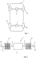
- the vehicle 1 is provided with a front axle 2 which is configured to provide drive torque to left and right front wheels 2a-b, and a rear axle 4 which is configured to provide drive torque to left and right rear wheels 4a-b.
- the front axle 2 may be driven by a combustion engine (not shown) or by an electrical machine (not shown).
- the rear axle 4 is also capable of providing torque vectoring.
- the general construction of the rear axle 4 is shown schematically in Fig. 2 .
- the vehicle axle 4 comprises an electrical machine 6, preferably arranged concentrically on the vehicle axle 4.
- the electrical machine 6 has an output shaft 8 which rotates upon activation of the electrical machine 6.
- a reduction gear (not shown) is provided to reduce the rotational speed of the output shaft 8.
- the output shaft 8 forms an input shaft to two clutches 10, 20.
- the first clutch 10 has an output shaft 12 which is connected to a left drive shaft 14.
- the left drive shaft 14 is providing drive torque to the left rear wheel 4a (see Fig. 1 ).
- the second clutch 20 has an output shaft 22 which is connected to a right drive shaft 24.
- the right drive shaft 24 is providing drive torque to the right rear wheel 4b (see Fig. 1 ).
- FIG. 3 an example of parts of vehicle axle 4 is shown.
- the electrical machine 6 is driving the shaft 8 which forms an output shaft of the electrical machine 6, as well as a common input shaft for both clutches 10, 20.
- Each clutch 10, 20 comprises an output shaft 12, 22 which is selectively connected to the input shaft 8 by a set of hydraulically actuated discs 16, 26.
- the set of discs 16 Upon actuation of the first clutch 10, the set of discs 16 is compressed such that torque from the input shaft 8 is transferred to the output shaft 12.
- the set of discs 26 upon actuation of the second clutch 20, the set of discs 26 is compressed such that torque from the input shaft 8 is transferred to the output shaft 26.
- the input shaft 8 is hollow in order to allow the output shaft 22 of the second clutch 20 to extend through towards the right wheel 4b.
- the output shaft 12 of the first clutch 10 extends in the opposite direction towards the left wheel 4a.
- the first and second clutches 10, 20 are arranged concentrically, radially outwards the output shafts 12, 22.
- the set of discs 16 of the first clutch 10 is arranged radially outwards of the set of discs 26 of the second clutch 20.
- the set of discs 16 of the first clutch 10 is arranged radially outside the input shaft 8
- the set of discs 26 of the second clutch 20 is arranged radially inside the input shaft 8.
- the clutches 10, 20, and in particular the set of discs 16 of the first clutch 10 and the set of discs 26 of the second clutch 20 overlap in the axial direction, preferably by at least 50%.
- the first clutch 10 comprises a piston 17 and a return spring 18.
- the piston 17 compresses the set of discs 16 upon application of a hydraulic pressure.
- the return spring 18 acts against the force of the piston 17, causing automatic separation of the set of discs 16 when the piston 17 is idle.
- the second clutch 20 comprises a piston 27 and a return spring 28.
- the piston 27 compresses the set of discs 26 upon application of a hydraulic pressure.
- the return spring 28 acts against the force of the piston 27, causing automatic separation of the set of discs 26 when the piston 27 is idle.
- the pressure being applied to the pistons 17, 27 is controlled by two separate actuators 30 (only one actuator is shown in Fig. 3 ).
- the first clutch 10 and the second clutch 20 are arranged in a common housing 40.
- the housing 40 accommodates the required high pressure hydraulics for both clutches 20, 30.
- each piston 17, 27 is radially aligned with the associated clutch 10, 20, and in particular with the set of discs 16, 26 of the respective clutch 10, 20.
- each piston 17, 27 is arranged at a radius coinciding with a radius of the clutch.
- the clutch 10, 20 is radially overlapping the associated piston 17, 27.
- at least an outer radius of the piston 17, 27 is arranged radially outwards of an inner radius of the clutch 10, 20.
- the inner radius of the clutch is smaller than the inner radius of the piston, and the outer radius of the clutch is greater than the outer radius of the piston.
- the pistons 17, 27 are axially overlapping, but radially separated.
- the input shaft 8 is axially supported by a bearing 50, positioned between the housing 40 and the input shaft 8.
- the axial bearing 50 allows the input shaft 8 to rotate relative the housing 40, and accommodates the axial forces transmitted through the clutches 10, 20.
- the disc clutches are axially supported by the bearing 50.
- the axial bearing 50 is radially positioned somewhere between the outer radius of the first clutch 10, and the inner radius of the second clutch 20. Hence, the axial bearing 50 is radially aligned with the clutches 10, 20.
- a vehicle axle 4 Further details of a vehicle axle 4 is shown in Fig. 4 .
- the input shaft 8, the clutches 10, 20, and the output shafts 12, 22 are all concentrically arranged around a central axis R1.
- the housing 40 surrounds the clutches 10, 20, and is in fluid communication with a reservoir 50 arranged radially outside the housing 40.
- Clutch fluid such as cooling and lubrication oil, is allowed to flow to and from the reservoir 50.
- rotation of the set of disc 16, 26 will throw the clutch fluid by a centrifugal force.
- the clutch fluid will exit the housing 40 through an open channel 52 that is arranged at the upper part of the housing 40.
- the open channel 52 extends into the reservoir 50, which thereby receives the clutch fluid from the housing 40.
- a valve 54 is arranged at the bottom part of the reservoir 50.
- the valve 54 is a shut-off valve which opens automatically when the clutches 10, 20 are in a connected mode such that during normal operation, clutch fluid will circulate from the housing 40 to the reservoir 50 via the channel 52, and back to the housing 40 through the open valve 54.
- the fluid level inside the reservoir 50 during normal operation is indicated by the level L1.
- valve 54 When the clutches 10, 20 are disengaged the valve 54 is automatically closed, such that clutch fluid in the reservoir 50 is prevented from returning to the housing 40. As the discs will still rotate the clutch fluid inside the housing 40 will be thrown back to the reservoir 50 whereby the housing will be drained. The fluid level of the reservoir 50 will thereby increase, as indicated by level L2. This automatic drainage reduces drag losses during disconnect mode.
- each clutch 10, 20 is controlled by a separate actuator 30.
- actuator 30 For the embodiments described above, requiring two actuators 30, these are preferably identical.
- the actuator 30 comprises an electronic control unit 32, an electrical motor 34, and a pump 36. All these components are assembled as a fully integrated device.
- the electronic control unit 32 is configured to control the operation of the electrical motor 34 according to functional safety requirements and preferably by applying cyber security and encryption of all control signals.
- the electrical motor preferably in the form of an BLDC is driving the pump 36, preferably in the form of a centrifugal pump.
- a method 100 for controlling the drive torque to a vehicle axle 4 comprises a first step 102 of determining a desired torque to a left drive shaft 14 and a right drive shaft 24 of the vehicle axle 4. This step 102 is preferably performed by monitoring driving characteristics of the associated vehicle 1, and to calculate optimum torque amount.
- a step 104 which in normal conditions is performed simultaneously as step 102, the electrical machine 6 of the vehicle axle 4 is controlled to a desired speed.
- step a first clutch 10 of the vehicle axle 4 is actuated by applying a pressure corresponding to the desired torque of the left drive shaft 14 and a second clutch 20 of the vehicle axle 4 is actuated by applying a pressure corresponding to the desired torque of the right drive shaft 24.
Landscapes
- Engineering & Computer Science (AREA)
- Mechanical Engineering (AREA)
- Chemical & Material Sciences (AREA)
- Combustion & Propulsion (AREA)
- Transportation (AREA)
- General Engineering & Computer Science (AREA)
- Fluid Mechanics (AREA)
- Physics & Mathematics (AREA)
- Hydraulic Clutches, Magnetic Clutches, Fluid Clutches, And Fluid Joints (AREA)
- Retarders (AREA)
- Motor Power Transmission Devices (AREA)
- Hybrid Electric Vehicles (AREA)
- Arrangement And Mounting Of Devices That Control Transmission Of Motive Force (AREA)
Abstract
Description
- The present invention relates to an electrical drive axle for a vehicle. In particular, the present invention relates to an electrical axle allowing torque vectoring between the left and right wheel.
- In the global effort to develop electrically driven vehicles numerous solutions have been presented addressing various objects such as reduced power consumption, compactness, improved driving performance, cost reduction, to name a few.
- One suggested electric driveline is to have separately driven axles in order to allow for selective two-wheel drive and four-wheel drive, where in particular the rear axle of the vehicle is electrically driven. To improve yaw control during acceleration and deceleration of the vehicle the rear axle may be provided with torque vectoring functionality, i.e. the possibility to control the individual torque acting on the left and right wheel, respectively.
- The drive torque for the rear axle is provided by means of an electrical machine which applies the desired driving torque as input to a differential having a first drive shaft connected to the left rear wheel, and a second drive shaft connected to the right rear wheel. In order to enable torque vectoring, additional gear trains are added to the differential in order to shuffle torque between the first and second drive shafts.
- Another solution for allowing torque vectoring to an electrically driven rear axle is to have a first electrical machine driving the first drive shaft, and a second electrical machine driving the second drive shaft. By independent control of these two electrical machines it is possible to adjust the drive torque supplied to the respective wheels. However, the need for two electrical machines greatly increases complexity and cost.
- In view of the above-mentioned examples of prior art there is need for an improved electrically driven axle which requires a single electrical machine without the need for additional gear trains.
- Accordingly, the present invention preferably seeks to mitigate, alleviate or eliminate one or more of the above-identified deficiencies in the art and disadvantages singly or in any combination and solves at least the above-mentioned problems by providing a vehicle axle according to the appended claims.
- According to a first aspect an electrically driven vehicle axle is provided. The vehicle axle comprises an electrical machine, a left drive shaft, a right drive shaft, a first clutch connecting the electrical machine to the left drive shaft and a second clutch connecting the electrical machine to the right drive shaft. The first and second clutches are arranged concentrically.
- The first and second clutches may be axially overlapping. The first and second clutches may be arranged at different radius. The first and second clutches may be axially overlapping, but radially separated. This allows for a very compact solution, especially in the axial direction of the vehicle axle. Hence, more axial space is available for other vehicle axle components, such as the electrical machine.
- The first and second clutches may be hydraulically actuated disc clutches. This is advantageous in that it provides for improved torque control, increased response time and superior accuracy.
- Each disc clutch may be actuated by a respective piston. Preferably, each piston is radially aligned with the associated clutch, i.e. arranged at a radius coinciding with a radius of the clutch. Generally, the radial extension of the clutch is greater than the radial extension of the associated piston. Preferably, the piston extends between an inner radius and an outer radius, and the clutch extends between an inner radius and an outer radius. At least the outer radius of the piston is arranged radially outwards of the inner radius of the clutch. Preferably, the inner radius of the clutch is smaller than the inner radius of the piston, and the outer radius of the clutch is greater than the outer radius of the piston.
- The pistons may be axially overlapping. The pistons may be radially separated. Preferably, the pistons may be axially overlapping, but radially separated.
- The disc clutches may be axially supported by at least one bearing. The bearing may be radially aligned with the associated clutch, i.e .arranged at a radius coinciding with a radius of the clutch. Generally, the radial extension of the clutch is greater than the radial extension of the associated bearing. Preferably, the bearing extends between an inner radius and an outer radius, and the clutch extends between an inner radius and an outer radius. At least the outer radius of the bearing is arranged radially outwards of the inner radius of the clutch. Preferably, the inner radius of the clutch is smaller than the inner radius of the bearing, and the outer radius of the clutch is greater than the outer radius of the bearing.
- Radial aligning of the pistons and/or axial bearings with the clutches reduces the risk for deflections of the vehicle axle assembly, which are due to the high forces required for the desired torque transfer. It has also been proven that the concept of radial alignment of axial bearings and/or actuation pistons reduces weight and response time.
- The vehicle axle may further comprise an input shaft being provided with a first set of discs arranged radially inwards to form discs of the first clutch, and a second set of discs arranged radially outwards to form discs of the second clutch. By using a common input shaft for the two clutches the complexity of the vehicle axle is greatly reduced.
- The electrical machine may be in driving connection with said input shaft. This allows for concentric mounting of the electrical machine onto the vehicle axle, reducing the need for additional gear trains.
- Each clutch may be provided with a return spring for disconnecting the left and right drive shaft from the electrical machine. Automatic disc separation is thereby achieved for both clutches.
- Each clutch may be controlled by a separate hydraulic actuator. This enables individual torque control for each clutch which allows for efficient and accurate torque vectoring of the vehicle axle.
- The first and second clutches may be arranged in a common housing. This is advantageous in that all high pressure hydraulics may be arranged in a single housing, thereby reducing the complexity of the vehicle axle.
- The housing may be in fluid connection with an external oil reservoir. It is thus possible to control the amount of hydraulic fluid inside the common housing for reducing losses during disconnect mode of the clutches.
- The oil reservoir may be provided with an oil inlet receiving oil from the first and second clutches, and an oil outlet for distributing oil to the first and second clutches. Efficient distribution to and from the clutches is thereby achieved.
- The oil outlet may be provided with a shut-off valve for automatically closing said oil outlet when the first and second clutches are in a disconnected mode. Automatic drainage of the housing is thereby provided
- According to a second aspect a vehicle is provided. The vehicle comprises a vehicle axle according to the first aspect.
- According to a third aspect a method for controlling the drive torque to a vehicle axle is provided. The method comprises i) determining a desired torque to a left drive shaft and a right drive shaft of the vehicle axle, ii) activating an electrical machine of the vehicle axle, and iii) actuating a first clutch of the vehicle axle by applying a pressure corresponding to the desired torque of the left drive shaft and actuating a second clutch of the vehicle axle by applying a pressure corresponding to the desired torque of the right drive shaft.
- The invention will be described in further detail below with reference to the accompanying drawings, in which
-
Fig. 1 is a schematic view of a vehicle according to an embodiment; -
Fig. 2 is a schematic view of a vehicle axle according to an embodiment; -
Fig. 3 is a cross-sectional view of parts of a vehicle axle according to an embodiment; -
Fig. 4 is another cross-sectional view of a vehicle axle according to an embodiment; -
Fig. 5 is a cross-sectional view of an actuator of a vehicle axle according to an embodiment; and -
Fig. 6 is a schematic view of a method for controlling drive torque according to an embodiment. - Several embodiments of the present invention will be described in more detail below with reference to the accompanying drawings in order for those skilled in the art to be able to carry out the invention. The invention may, however, be embodied in many different forms and should not be construed as limited to the embodiments set forth herein. Rather, these embodiments are provided so that this disclosure will be thorough and complete, and will fully convey the scope of the invention to those skilled in the art. The embodiments do not limit the invention, but the invention is only limited by the appended claims. Furthermore, the terminology used in the detailed description of the particular embodiments illustrated in the accompanying drawings is not intended to be limiting of the invention.
- Starting in
Fig. 1 , a vehicle 1 is schematically shown. The vehicle 1 is provided with afront axle 2 which is configured to provide drive torque to left and rightfront wheels 2a-b, and arear axle 4 which is configured to provide drive torque to left and rightrear wheels 4a-b. Although not described further herein, thefront axle 2 may be driven by a combustion engine (not shown) or by an electrical machine (not shown). - As will be explained in the following, by activation of the
rear axle 4 four-wheel drive, AWD, or rear-wheel drive, RWD, of the vehicle 1 is provided. Therear axle 4 is also capable of providing torque vectoring. - The general construction of the
rear axle 4 is shown schematically inFig. 2 . Thevehicle axle 4 comprises anelectrical machine 6, preferably arranged concentrically on thevehicle axle 4. Theelectrical machine 6 has anoutput shaft 8 which rotates upon activation of theelectrical machine 6. Optionally, a reduction gear (not shown) is provided to reduce the rotational speed of theoutput shaft 8. - The
output shaft 8 forms an input shaft to twoclutches output shaft 12 which is connected to aleft drive shaft 14. Theleft drive shaft 14 is providing drive torque to the leftrear wheel 4a (seeFig. 1 ). The second clutch 20 has anoutput shaft 22 which is connected to aright drive shaft 24. Theright drive shaft 24 is providing drive torque to the rightrear wheel 4b (seeFig. 1 ). - Now turning to
Fig. 3 , an example of parts ofvehicle axle 4 is shown. Although not shown inFig. 3 , theelectrical machine 6 is driving theshaft 8 which forms an output shaft of theelectrical machine 6, as well as a common input shaft for bothclutches - Each clutch 10, 20 comprises an
output shaft input shaft 8 by a set of hydraulically actuateddiscs discs 16 is compressed such that torque from theinput shaft 8 is transferred to theoutput shaft 12. In a similar manner, upon actuation of the second clutch 20, the set ofdiscs 26 is compressed such that torque from theinput shaft 8 is transferred to theoutput shaft 26. - The
input shaft 8 is hollow in order to allow theoutput shaft 22 of the second clutch 20 to extend through towards theright wheel 4b. Theoutput shaft 12 of the first clutch 10 extends in the opposite direction towards theleft wheel 4a. - The first and
second clutches output shafts discs 16 of the first clutch 10 is arranged radially outwards of the set ofdiscs 26 of thesecond clutch 20. As can be seen inFig. 3 the set ofdiscs 16 of the first clutch 10 is arranged radially outside theinput shaft 8, while the set ofdiscs 26 of the second clutch 20 is arranged radially inside theinput shaft 8. Theclutches discs 16 of the first clutch 10 and the set ofdiscs 26 of the second clutch 20 overlap in the axial direction, preferably by at least 50%. - The first clutch 10 comprises a
piston 17 and areturn spring 18. Thepiston 17 compresses the set ofdiscs 16 upon application of a hydraulic pressure. Thereturn spring 18 acts against the force of thepiston 17, causing automatic separation of the set ofdiscs 16 when thepiston 17 is idle. - In a similar manner the second clutch 20 comprises a
piston 27 and areturn spring 28. Thepiston 27 compresses the set ofdiscs 26 upon application of a hydraulic pressure. Thereturn spring 28 acts against the force of thepiston 27, causing automatic separation of the set ofdiscs 26 when thepiston 27 is idle. - The pressure being applied to the
pistons Fig. 3 ). - The first clutch 10 and the second clutch 20 are arranged in a
common housing 40. Thehousing 40 accommodates the required high pressure hydraulics for bothclutches - As can be seen in
Fig. 3 eachpiston discs piston piston piston Fig. 3 the inner radius of the clutch is smaller than the inner radius of the piston, and the outer radius of the clutch is greater than the outer radius of the piston. - The
pistons - As is further shown in
Fig. 3 theinput shaft 8 is axially supported by abearing 50, positioned between thehousing 40 and theinput shaft 8. Theaxial bearing 50 allows theinput shaft 8 to rotate relative thehousing 40, and accommodates the axial forces transmitted through theclutches bearing 50. For improved force accommodation theaxial bearing 50 is radially positioned somewhere between the outer radius of the first clutch 10, and the inner radius of thesecond clutch 20. Hence, theaxial bearing 50 is radially aligned with theclutches - Further details of a
vehicle axle 4 is shown inFig. 4 . Theinput shaft 8, theclutches output shafts housing 40 surrounds theclutches reservoir 50 arranged radially outside thehousing 40. Clutch fluid, such as cooling and lubrication oil, is allowed to flow to and from thereservoir 50. During operation of thevehicle axle 4, i.e. when theclutches disc housing 40 through anopen channel 52 that is arranged at the upper part of thehousing 40. Theopen channel 52 extends into thereservoir 50, which thereby receives the clutch fluid from thehousing 40. Avalve 54 is arranged at the bottom part of thereservoir 50. Thevalve 54 is a shut-off valve which opens automatically when theclutches housing 40 to thereservoir 50 via thechannel 52, and back to thehousing 40 through theopen valve 54. The fluid level inside thereservoir 50 during normal operation is indicated by the level L1. - When the
clutches valve 54 is automatically closed, such that clutch fluid in thereservoir 50 is prevented from returning to thehousing 40. As the discs will still rotate the clutch fluid inside thehousing 40 will be thrown back to thereservoir 50 whereby the housing will be drained. The fluid level of thereservoir 50 will thereby increase, as indicated by level L2. This automatic drainage reduces drag losses during disconnect mode. - Now turning to
Fig. 5 details of theactuators 30 will be described. As explained earlier, each clutch 10, 20 is controlled by aseparate actuator 30. For the embodiments described above, requiring twoactuators 30, these are preferably identical. - The
actuator 30 comprises anelectronic control unit 32, anelectrical motor 34, and apump 36. All these components are assembled as a fully integrated device. Theelectronic control unit 32 is configured to control the operation of theelectrical motor 34 according to functional safety requirements and preferably by applying cyber security and encryption of all control signals. The electrical motor, preferably in the form of an BLDC is driving thepump 36, preferably in the form of a centrifugal pump. - Now turning to
Fig. 6 , amethod 100 for controlling the drive torque to avehicle axle 4 is provided. The method comprises afirst step 102 of determining a desired torque to aleft drive shaft 14 and aright drive shaft 24 of thevehicle axle 4. Thisstep 102 is preferably performed by monitoring driving characteristics of the associated vehicle 1, and to calculate optimum torque amount. In astep 104, which in normal conditions is performed simultaneously asstep 102, theelectrical machine 6 of thevehicle axle 4 is controlled to a desired speed. In step 106 afirst clutch 10 of thevehicle axle 4 is actuated by applying a pressure corresponding to the desired torque of theleft drive shaft 14 and asecond clutch 20 of thevehicle axle 4 is actuated by applying a pressure corresponding to the desired torque of theright drive shaft 24. - It should be mentioned that the inventive concept is by no means limited to the embodiments described herein, and several modifications are feasible without departing from the scope of the invention as defined in the appended claims.
Claims (15)
- An electrically driven vehicle axle (4), comprising an electrical machine (6), a left drive shaft (14), a right drive shaft (24), a first clutch (10) connecting the electrical machine (6) to the left drive shaft (14) and a second clutch (20) connecting the electrical machine (6) to the right drive shaft (24), wherein the first and second clutches (10, 20) are arranged concentrically.
- The vehicle axle according to claim 1, wherein the first and second clutches (10, 20) are axially overlapping, and/or wherein the first and second clutches (10, 20) are arranged at different radius.
- The vehicle axle according to any of the preceding claims, wherein the first and second clutches (10, 20) are hydraulically actuated disc clutches.
- The vehicle axle according to any of the preceding claims, further comprising two pistons (17, 27), wherein each clutch (10, 20) is actuated by a respective piston (17, 27), optionally wherein each piston (17, 27) is radially aligned with the associated clutch (10, 20).
- The vehicle axle according to claim 4, wherein the pistons (17, 27) are axially overlapping.
- The vehicle axle according to any of claims 4 or 5, wherein the pistons (17, 27) are arranged at different radius.
- The vehicle axle according to any of the preceding claims, wherein the clutches (10, 20) are axially supported by at least one bearing (50), optionally wherein the at least one bearing (50) is radially aligned with at least one of the clutches (10, 20).
- The vehicle axle according to any of the preceding claims, further comprising an input shaft (8) being provided with a first set of discs (216) arranged radially inwards to form discs of the first clutch (10), and a second set of discs (26) arranged radially outwards to form discs of the second clutch (20), optionally wherein the electrical machine (6) is in driving connection with said input shaft (8).
- The vehicle axle according to any of the preceding claims, wherein each clutch (10, 20) is provided with a return spring (18, 28) for disconnecting the left and right drive shaft (14, 24) from the electrical machine (6).
- The vehicle axle according to any of the preceding claims, wherein each clutch (10, 20) is controlled by a separate hydraulic actuator (30).
- The vehicle axle according to any of the preceding claims, wherein the first and second clutches (10, 20) are arranged in a common housing (40), optionally wherein said housing (40) is in fluid connection with an external oil reservoir (50).
- The vehicle axle according to claim 11, wherein said oil reservoir (50) is provided with an oil inlet (52) receiving oil from the first and second clutches (10, 20), and an oil outlet (54) for distributing oil to the first and second clutches (10, 20).
- The vehicle axle according to claim 12, wherein the oil outlet (54) is formed by a shut-off valve (54) for automatically closing when the first and second clutches (10, 20) are in a disconnected mode.
- A vehicle, comprising a vehicle axle (4) according to any of the preceding claims.
- A method for controlling the drive torque to a vehicle axle, comprising:determining a desired torque to a left drive shaft and a right drive shaft of the vehicle axle,activating an electrical machine, andactuating a first clutch by applying a pressure corresponding to the desired torque of the left drive shaft and actuating a second clutch by applying a pressure corresponding to the desired torque of the right drive shaft.
Applications Claiming Priority (1)
| Application Number | Priority Date | Filing Date | Title |
|---|---|---|---|
| SE2150344A SE546942C2 (en) | 2021-03-24 | 2021-03-24 | An electrical drive axle for a vehicle, a vehicle, and a method for controlling the axle |
Publications (2)
| Publication Number | Publication Date |
|---|---|
| EP4063155A1 true EP4063155A1 (en) | 2022-09-28 |
| EP4063155B1 EP4063155B1 (en) | 2025-12-24 |
Family
ID=80933423
Family Applications (1)
| Application Number | Title | Priority Date | Filing Date |
|---|---|---|---|
| EP22164068.3A Active EP4063155B1 (en) | 2021-03-24 | 2022-03-24 | An electrical drive axle for a vehicle |
Country Status (5)
| Country | Link |
|---|---|
| US (1) | US11981193B2 (en) |
| EP (1) | EP4063155B1 (en) |
| JP (1) | JP2022151820A (en) |
| CN (1) | CN115122825A (en) |
| SE (1) | SE546942C2 (en) |
Cited By (2)
| Publication number | Priority date | Publication date | Assignee | Title |
|---|---|---|---|---|
| WO2024074485A1 (en) * | 2022-10-03 | 2024-04-11 | Borgwarner Sweden Ab | A vehicle, and a control method for such vehicle |
| DE102024101588A1 (en) * | 2024-01-19 | 2025-07-24 | Schaeffler Technologies AG & Co. KG | Drive arrangement for a motor vehicle and drive for an electric motor vehicle |
Families Citing this family (1)
| Publication number | Priority date | Publication date | Assignee | Title |
|---|---|---|---|---|
| EP4088961B1 (en) * | 2021-05-12 | 2024-11-13 | Transmisiones Y Equipos Mecánicos, S.A. de C.V. | Drive system for variable distribution of torque to wheels of a vehicle |
Citations (4)
| Publication number | Priority date | Publication date | Assignee | Title |
|---|---|---|---|---|
| US20030037977A1 (en) * | 2001-08-27 | 2003-02-27 | Honda Giken Kogyo Kabushiki Kaisha | Drive force distribution apparatus for hybrid vehicle |
| DE102004058984A1 (en) * | 2004-12-08 | 2006-06-14 | Linde Ag | Driving axle e.g. industrial truck driving axle has hydraulic pump with electric motor which stays in drive connection or it can be placed in drive connection and detachable coupling is downstream in differential exits and brakes |
| DE102008040172A1 (en) * | 2008-07-04 | 2010-01-07 | Zf Friedrichshafen Ag | Multiple clutch device i.e. dual clutch device, for torque transmission in drive train of e.g. lorry, between drive arrangement and transmission arrangement, has outer disk carriers connected to outlet elements, respectively |
| US9657826B1 (en) * | 2016-08-17 | 2017-05-23 | Borgwarner Inc. | Electric motor with coaxial clutch packs that provide differential and torque vectoring |
Family Cites Families (18)
| Publication number | Priority date | Publication date | Assignee | Title |
|---|---|---|---|---|
| JPH02296041A (en) * | 1989-05-10 | 1990-12-06 | Aisin Aw Co Ltd | Clutch device of automatic transmission |
| US5310388A (en) * | 1993-02-10 | 1994-05-10 | Asha Corporation | Vehicle drivetrain hydraulic coupling |
| US5964126A (en) * | 1998-09-02 | 1999-10-12 | Mclaren Automotive Group, Inc. | Hydraulic coupling for auxiliary drive axle of a vehicle drivetrain |
| DE10004189C5 (en) * | 1999-09-30 | 2015-05-21 | Volkswagen Ag | Multiple clutch device |
| US7267627B2 (en) * | 2004-05-24 | 2007-09-11 | Magna Powertrain Usa, Inc. | Torque vectoring axle assembly |
| DE102010023840B4 (en) * | 2010-06-09 | 2022-12-01 | Magna Pt B.V. & Co. Kg | Friction clutch arrangement for a motor vehicle drive train |
| CN103917397A (en) * | 2011-11-10 | 2014-07-09 | 丰田自动车株式会社 | Electric drive device for vehicle |
| EP2888125B1 (en) * | 2012-08-27 | 2018-05-02 | GKN Automotive Ltd. | Mechanical and electric drive train of a motor vehicle and motor vehicle with mechanical and electric drive train |
| US9353846B2 (en) * | 2013-08-23 | 2016-05-31 | American Axle & Manufacturing, Inc. | Power transmitting component with torque transfer device configured with fluid evacuation and lubrication system |
| US9868349B2 (en) * | 2015-01-19 | 2018-01-16 | Borgwarner Inc. | E-assist with torque vectoring |
| US10113630B2 (en) * | 2016-01-08 | 2018-10-30 | Dana Automotive Systems Group, Llc | Drive unit for shifting a torque balance |
| DE102016218264A1 (en) * | 2016-09-22 | 2018-03-22 | Zf Friedrichshafen Ag | Triple clutch assembly, powertrain and motor vehicle |
| FR3060680B1 (en) * | 2016-12-21 | 2019-11-08 | Valeo Embrayages | TORQUE TRANSMISSION MODULE FOR EQUIPPING MOTOR VEHICLE TRANSMISSION |
| JP6410854B2 (en) * | 2017-01-24 | 2018-10-24 | 本田技研工業株式会社 | Hydraulic clutch device |
| DE102018124034A1 (en) * | 2018-01-24 | 2019-07-25 | Schaeffler Technologies AG & Co. KG | Coupling device and drive train with the coupling device and electrical axle for a vehicle |
| DE102018117939A1 (en) * | 2018-07-25 | 2020-01-30 | Schaeffler Technologies AG & Co. KG | Electric drive with cooled oil supply device |
| DE102018008912B3 (en) * | 2018-11-12 | 2020-01-09 | Daimler Ag | Hybrid dual-clutch transmission |
| JP2021067357A (en) * | 2019-10-28 | 2021-04-30 | 株式会社ジェイテクト | Vehicle drive system |
-
2021
- 2021-03-24 SE SE2150344A patent/SE546942C2/en unknown
-
2022
- 2022-03-22 US US17/701,111 patent/US11981193B2/en active Active
- 2022-03-23 JP JP2022047581A patent/JP2022151820A/en active Pending
- 2022-03-24 EP EP22164068.3A patent/EP4063155B1/en active Active
- 2022-03-24 CN CN202210301212.8A patent/CN115122825A/en active Pending
Patent Citations (4)
| Publication number | Priority date | Publication date | Assignee | Title |
|---|---|---|---|---|
| US20030037977A1 (en) * | 2001-08-27 | 2003-02-27 | Honda Giken Kogyo Kabushiki Kaisha | Drive force distribution apparatus for hybrid vehicle |
| DE102004058984A1 (en) * | 2004-12-08 | 2006-06-14 | Linde Ag | Driving axle e.g. industrial truck driving axle has hydraulic pump with electric motor which stays in drive connection or it can be placed in drive connection and detachable coupling is downstream in differential exits and brakes |
| DE102008040172A1 (en) * | 2008-07-04 | 2010-01-07 | Zf Friedrichshafen Ag | Multiple clutch device i.e. dual clutch device, for torque transmission in drive train of e.g. lorry, between drive arrangement and transmission arrangement, has outer disk carriers connected to outlet elements, respectively |
| US9657826B1 (en) * | 2016-08-17 | 2017-05-23 | Borgwarner Inc. | Electric motor with coaxial clutch packs that provide differential and torque vectoring |
Cited By (2)
| Publication number | Priority date | Publication date | Assignee | Title |
|---|---|---|---|---|
| WO2024074485A1 (en) * | 2022-10-03 | 2024-04-11 | Borgwarner Sweden Ab | A vehicle, and a control method for such vehicle |
| DE102024101588A1 (en) * | 2024-01-19 | 2025-07-24 | Schaeffler Technologies AG & Co. KG | Drive arrangement for a motor vehicle and drive for an electric motor vehicle |
Also Published As
| Publication number | Publication date |
|---|---|
| CN115122825A (en) | 2022-09-30 |
| US20220305893A1 (en) | 2022-09-29 |
| US11981193B2 (en) | 2024-05-14 |
| EP4063155B1 (en) | 2025-12-24 |
| JP2022151820A (en) | 2022-10-07 |
| SE2150344A1 (en) | 2022-09-25 |
| SE546942C2 (en) | 2025-03-11 |
Similar Documents
| Publication | Publication Date | Title |
|---|---|---|
| US11981193B2 (en) | Electrical drive axle for a vehicle | |
| EP2137422B1 (en) | Idle-able power transfer unit | |
| US8961369B2 (en) | Torque transfer unit with integrated electric drive motor | |
| US8596436B2 (en) | Idle-able auxiliary drive system | |
| EP2359018B1 (en) | Idle-able auxiliary drive system | |
| CN102606705A (en) | Torque converter with lock-up clutch | |
| US7534193B2 (en) | Coupling assembly | |
| JP2019529229A (en) | Integrated twin clutch system and dual action piston | |
| WO2010038148A1 (en) | Rear drive module wheel disconnect | |
| CN103133556B (en) | Clutch apparatus for vehicle drive train | |
| US11353097B2 (en) | Electric machine with fluid coupling | |
| JP4006148B2 (en) | Coupling | |
| JP4580877B2 (en) | Differential device | |
| JPH0840103A (en) | Left and right driving force adjustment device for vehicles | |
| JPH06193648A (en) | Multi-plate friction hydraulic clutch | |
| JP2000291687A (en) | Clutch device and differential device using the same |
Legal Events
| Date | Code | Title | Description |
|---|---|---|---|
| PUAI | Public reference made under article 153(3) epc to a published international application that has entered the european phase |
Free format text: ORIGINAL CODE: 0009012 |
|
| STAA | Information on the status of an ep patent application or granted ep patent |
Free format text: STATUS: THE APPLICATION HAS BEEN PUBLISHED |
|
| AK | Designated contracting states |
Kind code of ref document: A1 Designated state(s): AL AT BE BG CH CY CZ DE DK EE ES FI FR GB GR HR HU IE IS IT LI LT LU LV MC MK MT NL NO PL PT RO RS SE SI SK SM TR |
|
| STAA | Information on the status of an ep patent application or granted ep patent |
Free format text: STATUS: REQUEST FOR EXAMINATION WAS MADE |
|
| 17P | Request for examination filed |
Effective date: 20230328 |
|
| RBV | Designated contracting states (corrected) |
Designated state(s): AL AT BE BG CH CY CZ DE DK EE ES FI FR GB GR HR HU IE IS IT LI LT LU LV MC MK MT NL NO PL PT RO RS SE SI SK SM TR |
|
| GRAP | Despatch of communication of intention to grant a patent |
Free format text: ORIGINAL CODE: EPIDOSNIGR1 |
|
| STAA | Information on the status of an ep patent application or granted ep patent |
Free format text: STATUS: GRANT OF PATENT IS INTENDED |
|
| INTG | Intention to grant announced |
Effective date: 20250722 |
|
| GRAS | Grant fee paid |
Free format text: ORIGINAL CODE: EPIDOSNIGR3 |
|
| GRAA | (expected) grant |
Free format text: ORIGINAL CODE: 0009210 |
|
| STAA | Information on the status of an ep patent application or granted ep patent |
Free format text: STATUS: THE PATENT HAS BEEN GRANTED |
|
| AK | Designated contracting states |
Kind code of ref document: B1 Designated state(s): AL AT BE BG CH CY CZ DE DK EE ES FI FR GB GR HR HU IE IS IT LI LT LU LV MC MK MT NL NO PL PT RO RS SE SI SK SM TR |
|
| REG | Reference to a national code |
Ref country code: CH Ref legal event code: F10 Free format text: ST27 STATUS EVENT CODE: U-0-0-F10-F00 (AS PROVIDED BY THE NATIONAL OFFICE) Effective date: 20251224 Ref country code: GB Ref legal event code: FG4D |
|
| REG | Reference to a national code |
Ref country code: DE Ref legal event code: R096 Ref document number: 602022027266 Country of ref document: DE |
|
| PGFP | Annual fee paid to national office [announced via postgrant information from national office to epo] |
Ref country code: GB Payment date: 20260310 Year of fee payment: 5 |
|
| REG | Reference to a national code |
Ref country code: LT Ref legal event code: MG9D |
|
| PG25 | Lapsed in a contracting state [announced via postgrant information from national office to epo] |
Ref country code: NO Free format text: LAPSE BECAUSE OF FAILURE TO SUBMIT A TRANSLATION OF THE DESCRIPTION OR TO PAY THE FEE WITHIN THE PRESCRIBED TIME-LIMIT Effective date: 20260324 |
|
| PGFP | Annual fee paid to national office [announced via postgrant information from national office to epo] |
Ref country code: DE Payment date: 20260310 Year of fee payment: 5 |
|
| PG25 | Lapsed in a contracting state [announced via postgrant information from national office to epo] |
Ref country code: FI Free format text: LAPSE BECAUSE OF FAILURE TO SUBMIT A TRANSLATION OF THE DESCRIPTION OR TO PAY THE FEE WITHIN THE PRESCRIBED TIME-LIMIT Effective date: 20251224 Ref country code: HR Free format text: LAPSE BECAUSE OF FAILURE TO SUBMIT A TRANSLATION OF THE DESCRIPTION OR TO PAY THE FEE WITHIN THE PRESCRIBED TIME-LIMIT Effective date: 20251224 |
|
| PGFP | Annual fee paid to national office [announced via postgrant information from national office to epo] |
Ref country code: AT Payment date: 20260301 Year of fee payment: 5 |
|
| PG25 | Lapsed in a contracting state [announced via postgrant information from national office to epo] |
Ref country code: RS Free format text: LAPSE BECAUSE OF FAILURE TO SUBMIT A TRANSLATION OF THE DESCRIPTION OR TO PAY THE FEE WITHIN THE PRESCRIBED TIME-LIMIT Effective date: 20260324 |
|
| PGFP | Annual fee paid to national office [announced via postgrant information from national office to epo] |
Ref country code: FR Payment date: 20260310 Year of fee payment: 5 |
|
| PG25 | Lapsed in a contracting state [announced via postgrant information from national office to epo] |
Ref country code: LV Free format text: LAPSE BECAUSE OF FAILURE TO SUBMIT A TRANSLATION OF THE DESCRIPTION OR TO PAY THE FEE WITHIN THE PRESCRIBED TIME-LIMIT Effective date: 20251224 |