EP4063131A1 - Liquid discharging apparatus - Google Patents
Liquid discharging apparatus Download PDFInfo
- Publication number
- EP4063131A1 EP4063131A1 EP22164165.7A EP22164165A EP4063131A1 EP 4063131 A1 EP4063131 A1 EP 4063131A1 EP 22164165 A EP22164165 A EP 22164165A EP 4063131 A1 EP4063131 A1 EP 4063131A1
- Authority
- EP
- European Patent Office
- Prior art keywords
- less
- liquid
- inner diameter
- reservoir
- nozzle
- Prior art date
- Legal status (The legal status is an assumption and is not a legal conclusion. Google has not performed a legal analysis and makes no representation as to the accuracy of the status listed.)
- Granted
Links
Images






Classifications
-
- B—PERFORMING OPERATIONS; TRANSPORTING
- B41—PRINTING; LINING MACHINES; TYPEWRITERS; STAMPS
- B41J—TYPEWRITERS; SELECTIVE PRINTING MECHANISMS, i.e. MECHANISMS PRINTING OTHERWISE THAN FROM A FORME; CORRECTION OF TYPOGRAPHICAL ERRORS
- B41J2/00—Typewriters or selective printing mechanisms characterised by the printing or marking process for which they are designed
- B41J2/005—Typewriters or selective printing mechanisms characterised by the printing or marking process for which they are designed characterised by bringing liquid or particles selectively into contact with a printing material
- B41J2/01—Ink jet
- B41J2/17—Ink jet characterised by ink handling
- B41J2/175—Ink supply systems ; Circuit parts therefor
- B41J2/17503—Ink cartridges
- B41J2/17513—Inner structure
-
- B—PERFORMING OPERATIONS; TRANSPORTING
- B41—PRINTING; LINING MACHINES; TYPEWRITERS; STAMPS
- B41J—TYPEWRITERS; SELECTIVE PRINTING MECHANISMS, i.e. MECHANISMS PRINTING OTHERWISE THAN FROM A FORME; CORRECTION OF TYPOGRAPHICAL ERRORS
- B41J2/00—Typewriters or selective printing mechanisms characterised by the printing or marking process for which they are designed
- B41J2/005—Typewriters or selective printing mechanisms characterised by the printing or marking process for which they are designed characterised by bringing liquid or particles selectively into contact with a printing material
- B41J2/01—Ink jet
- B41J2/135—Nozzles
- B41J2/14—Structure thereof only for on-demand ink jet heads
-
- B—PERFORMING OPERATIONS; TRANSPORTING
- B41—PRINTING; LINING MACHINES; TYPEWRITERS; STAMPS
- B41J—TYPEWRITERS; SELECTIVE PRINTING MECHANISMS, i.e. MECHANISMS PRINTING OTHERWISE THAN FROM A FORME; CORRECTION OF TYPOGRAPHICAL ERRORS
- B41J2/00—Typewriters or selective printing mechanisms characterised by the printing or marking process for which they are designed
- B41J2/005—Typewriters or selective printing mechanisms characterised by the printing or marking process for which they are designed characterised by bringing liquid or particles selectively into contact with a printing material
- B41J2/01—Ink jet
- B41J2/135—Nozzles
- B41J2/14—Structure thereof only for on-demand ink jet heads
- B41J2/14201—Structure of print heads with piezoelectric elements
-
- B—PERFORMING OPERATIONS; TRANSPORTING
- B41—PRINTING; LINING MACHINES; TYPEWRITERS; STAMPS
- B41J—TYPEWRITERS; SELECTIVE PRINTING MECHANISMS, i.e. MECHANISMS PRINTING OTHERWISE THAN FROM A FORME; CORRECTION OF TYPOGRAPHICAL ERRORS
- B41J2/00—Typewriters or selective printing mechanisms characterised by the printing or marking process for which they are designed
- B41J2/005—Typewriters or selective printing mechanisms characterised by the printing or marking process for which they are designed characterised by bringing liquid or particles selectively into contact with a printing material
- B41J2/01—Ink jet
- B41J2/17—Ink jet characterised by ink handling
- B41J2/175—Ink supply systems ; Circuit parts therefor
- B41J2/17503—Ink cartridges
-
- B—PERFORMING OPERATIONS; TRANSPORTING
- B41—PRINTING; LINING MACHINES; TYPEWRITERS; STAMPS
- B41J—TYPEWRITERS; SELECTIVE PRINTING MECHANISMS, i.e. MECHANISMS PRINTING OTHERWISE THAN FROM A FORME; CORRECTION OF TYPOGRAPHICAL ERRORS
- B41J2/00—Typewriters or selective printing mechanisms characterised by the printing or marking process for which they are designed
- B41J2/005—Typewriters or selective printing mechanisms characterised by the printing or marking process for which they are designed characterised by bringing liquid or particles selectively into contact with a printing material
- B41J2/01—Ink jet
- B41J2/17—Ink jet characterised by ink handling
- B41J2/175—Ink supply systems ; Circuit parts therefor
- B41J2/17503—Ink cartridges
- B41J2/1752—Mounting within the printer
Definitions
- the present invention relates to a liquid discharging apparatus having a head configured to discharge a liquid supplied from a reservoir.
- an ink-jet pen As an apparatus which discharges an ink stored in a tank from a nozzle so as to perform recording of an image, an ink-jet pen is known (see Patent Literature 1).
- a liquid surface of the ink stored in an ink cartridge is positioned above an opening of the nozzle.
- a gas layer is not communicated with outside, or a valve is provided on a gas channel which communicates the gas layer to the outside.
- Patent Literature 1 Japanese Patent Application Laid-Open No. JP S55-65560
- the present invention has been made in view of the above-described situation, and an object of the present invention is to provide means for maintaining the meniscus formed in the opening of the nozzle in a state that a reservoir in which a liquid is stored is communicated with the outside of the reservoir by an atmosphere port.
- An inner diameter d of the nozzle and a head difference h satisfy the expression of phd / ⁇ cos ⁇ ⁇ 4 / g, provided that ⁇ is a specific weight of the liquid, ⁇ is a surface tension of the liquid, ⁇ is a contact angle of the liquid in the nozzle and g is gravitational acceleration, the head difference h being a difference in height between a meniscus formed in the opening of the nozzle and the liquid surface in the state that the reservoir stores the liquid of the maximum storable amount.
- the meniscus formed in the opening of the nozzle is maintained in a state that the reservoir in which the liquid is stored is communicated with the outside of the reservoir by the atmosphere port.
- the meniscus formed in the opening of the nozzle is maintained in a state that the reservoir in which the liquid is stored is communicated with the outside of the reservoir by the atmosphere port.
- a front-rear direction 8 is defined, with a side on which an opening 13 is provided being defined as a front surface 23; and a left-right direction 9 is defined, with the multifunction peripheral 10 as seen from the front side.
- the up-down direction 7, the front-rear direction 8, and the left-right direction 9 are orthogonal to one another.
- the multifunction peripheral 10 (an example of a "liquid discharging apparatus") has a casing (housing) 14 which has a substantially rectangular parallelepiped shape.
- a printer part 11 is provided at a lower part of the casing 14.
- the multifunction peripheral 10 has a various kinds of functions such as a facsimile function, a print function, etc.
- the multifunction peripheral 10 has a function, as the print function, of recording an image on one surface of a sheet 12 (paper sheet 12; see FIG. 2 ) in an ink-jet system. Note that the multifunction peripheral 10 may also be configured to record an image on both surfaces of the sheet 12.
- An operating part 17 is provided on an upper part of the casing 14.
- the operating part 17 is constructed of a button configured to be operated for instructing the image recording, for performing a various kinds of settings, etc., a liquid crystal display configured to display a various kinds of information thereon, and the like.
- the operating part 17 is constructed of a touch panel having both of the function of the button and the function of the liquid crystal display.
- the printer part 11 has a feed tray 20, a feeding part 16, an outer guide member 18, an inner guide member 19, a conveying roller pair 59, a discharging roller pair 44, a platen 42, a recording part 24, an encoder 35 (see FIG. 4 ), a rotary encoder 75 (see FIG. 4 ), a controller 130 (see FIG. 4 ) and a memory 140 (see FIG. 4 ) which are arranged inside the casing 14.
- a various kinds of state sensors (not depicted in the drawings), which are configured to detect the state of the multifunction peripheral 10 and to output a signal in accordance with a result of detection, are arranged.
- an opening 13 is formed in the front surface 23 of the printer part 11.
- the feed tray 20 is insertable and removable with respect to the casing 14 via the opening 13, by moving in the front-rear direction 8.
- the feed tray 20 is movable between a feeding position (a position depicted in FIGs. 1 and 2 ) at which the feed tray 20 is installed in the casing 14, and a non-feeding position at which the feed tray 20 is removed (detached) from the casing 14.
- the feed tray 20 is inserted rearward with respect to the casing 14 to be moved to the feeding position, and the feed tray 20 is pulled frontward with respect to the casing 14 to be moved to the non-feeding position.
- the feed tray 20 is a member having a box-like shape of which upper part is opened, and is configured to store a sheet 12. As depicted in FIG. 2 , a plurality of pieces of the sheet 12 are supported by a bottom plate 22 of the feed tray 20 in a state that the sheets 12 are overlaid on each other.
- the discharge tray 21 is arranged at a location which is above a front part of the feed tray 20. A sheet 12 on which image recording has been performed by the recording part 24 and which is discharged is supported by an upper surface of the discharge tray 21. In a case that the feed tray 20 is at the feeding position, the sheet 12 supported by the feed tray 20 is allowed to be fed to a conveying route 65.
- the feeding part 16 is arranged at a location below the recording part 24 and above the bottom plate 22 of the feed tray 20.
- the feeding part 16 is provided with a feeding roller 25, a feeding arm 26, a driving transmitting mechanism 27 and a shaft 28.
- the feeding roller 25 is supported rotatably at a forward end part of the feeding arm 26.
- the feeding arm 26 rotates in a direction of an arrow 29, with the shaft 28 provided on a base part of the feeding arm 26 as the center of rotation. With this, the feeding roller 25 is capable of making contact with and separating away from the feed tray 20 or the sheet 12 which is supported by the feed tray 20.
- the feeding roller 25 rotates by a driving force, of a feeding motor 102 (see FIG. 4 ), which is transmitted to the feeding roller 25 by the driving transmitting mechanism 27 constructed of a plurality of gears meshed with each other. With this, among the sheets 12 supported by the bottom plate 22 of the feed tray 20 at the feeding position, an uppermost sheet 12 which makes contact with the feeding roller 25 is fed to the conveying route 65.
- the driving transmitting mechanism 27 is not limited to or restricted by the aspect in which the plurality of gears are meshed with each other; for example, the driving transmitting mechanism 27 may be a belt which is stretched or spanned between the shaft 28 and the shaft of the feeding roller 25.
- the conveying route 65 is extended from a rear end part of the feed tray 20.
- the conveying route 65 includes a curved part 33 and a straight part 34.
- the curved part 33 extends toward the upper side while making a U-turn from the rear side to the front side.
- the straight part 34 extends substantially along the front-rear direction 8.
- the curved part 33 is formed by the outer guide member 18 and the inner guide member 19 which face or are opposite to each other, with a predetermined spacing distance therebetween.
- the outer guide member 18 and the inner guide member 19 are provided to extend in the left-right direction 9.
- the straight part 34 is formed by the recording part 24 and the platen 42 which face each other with a predetermined spacing distance therebetween.
- the sheet 12 supported by the feed tray 20 is conveyed in the curved part 33 by the feeding roller 25, and reaches the conveying roller pair 59.
- the sheet 12 pinched or held by the conveying roller pair 59 is conveyed frontward in the straight part 34 toward the recording part 24.
- the recording part 24 records an image on the sheet 12 which has reached a location immediately below the recording part 24.
- the sheet 12 having the image recorded thereon is conveyed frontward in the straight part 34, and is discharged to the discharge tray 21.
- the sheet 12 is conveyed along a conveying orientation 15 which is indicated by an arrow of an alternate long and short dash line in FIG. 2 .
- the conveying roller pair 59 is arranged in the straight part 34.
- the discharging roller pair 44 is arranged, in the straight part 34, on the downstream side in the conveying orientation 15 with respect to the conveying roller pair 59.
- the conveying roller pair 59 includes a conveying roller 60 and a pinch roller 61 which is arranged at a location below the conveying roller 60 so as to face the conveying roller 60.
- the pinch roller 61 is pressed toward the conveying roller 60 by an elastic member (not depicted in the drawings) such as a coil spring, etc.
- the conveying roller pair 59 is capable of pinching or holding the sheet 12 therebetween.
- the discharging roller pair 44 includes a discharging roller 62 and a spur roller 63 which is arranged at a location above the discharging roller 62 so as to face the discharging roller 62.
- the spur roller 63 is pressed toward the discharging roller 62 by an elastic member (not depicted in the drawings) such as a coil spring, etc.
- the discharging roller pair 44 is capable of pinching or holding the sheet 12 therebetween.
- the conveying roller 60 and the discharging roller 62 rotate in a case that a driving force is applied to the conveying roller 60 and the discharging roller 62 from the conveying motor 101 (see FIG. 4 ).
- the conveying roller 60 rotates in a state that the sheet 12 is pinched by the conveying roller pair 59
- the sheet 12 is conveyed in the conveying orientation 15 by the conveying roller pair 59, and is conveyed onto the platen 42.
- the discharging roller 62 rotates in a state that the sheet 12 is pinched by the discharging roller pair 44
- the sheet 12 is conveyed in the conveying orientation 15 by the discharging roller pair 44, and is discharged onto the discharge tray 21.
- a common motor may be used as the conveying motor 101 and the feeding motor 102. In such a case, there is provided a configuration wherein a driving transmitting route from the common motor to each of the rollers is switchable.
- a mechanism or member configured to convey the sheet 12 is not limited to the roller pairs as described above.
- a conveying belt is arranged, instead of the conveying roller pair 59 and the discharging roller pair 44.
- the platen 42 is arranged in the straight part 34 of the conveying route 65.
- the platen 42 faces the recording part 24 in the up-down direction 7.
- the platen 42 supports the sheet 12 which is being conveyed in the conveying route 65 from therebelow.
- the sheet 12 which is being conveyed in the conveying route 65 passes an area between a right end and a left end of the platen 42 in the left-right direction 9 (hereinafter referred to as a "medium passing area").
- the recording part 24 is arranged at a location above the platen 42 so as to face the platen 42.
- the recording part 24 is provided with a carriage 40, a head 38 and a reservoir (storing part, storage) 80.
- the carriage 40 is supported to be movable in the left-right direction 9 (an example of a "scanning direction") which is orthogonal to the conveying orientation 15, by two guide rails 56 and 57 which are arranged in the front-rear direction 8 with a spacing distance therebetween.
- the carriage 40 is movable, in the left-right direction 9, between a position on the right side with respect to the medium passing area and a position on the left side with respect to the medium passing area.
- the moving direction of the carriage 40 is not limited to the left-right direction 9, and the moving direction may be a direction crossing the conveying orientation 15.
- the guide rail 56 is arranged on the upstream side in the conveying orientation 15 with respect to the head 38.
- the guide rail 57 is arranged on the downstream side in the conveying orientation 15 with respect to the head 38.
- the guide rails 56 and 57 are supported by a pair of side frames (not depicted in the drawings) which are arranged, in the left-right direction 9, at the outside of the straight part 34 of the conveying route 65.
- the carriage 40 is moved in a case that a driving force is applied to the carriage 40 from a carriage driving motor 103 (see FIG. 4 ).
- the encoder 35 (see FIG. 4 ) is arranged in the guide rail 56 or the guide rail 57.
- the encoder 35 includes an encoder strip extending in the left-right direction 9, and an optical sensor which is provided, on the carriage 40, at a location facing the encoder strip.
- a pattern, in which light transmitting parts each configured to allow a light to transmit therethrough and light shielding parts each configured to shield the light are alternately arranged at an equal pitch in the left-right direction 9, is formed in the encoder strip.
- the optical sensor detects the light transmitting parts and the light shielding parts, thereby detecting a pulse signal.
- the pulse signal is a signal in accordance with the position in the left-right direction 9 of the carriage 40.
- the pulse signal is outputted to the controller 130 (see FIG. 4 ).
- the head 38 is supported by the carriage 40. A lower surface 68 of the head 38 is exposed downward, and faces the platen 42.
- the head 38 is provided with a plurality of nozzles 39, an ink channel 37 and a piezoelectric element 45 (see FIG. 4 ).
- the plurality of nozzles 39 are opened in the lower surface 68 of the head 38.
- the ink channel 37 connects or links the reservoir 80 and the plurality of nozzles 39.
- the piezoelectric element 45 deforms a part of the ink channel 37 to thereby cause a droplet of an ink (ink droplet) to be discharged or ejected downward from the nozzles 39.
- the piezoelectric element 45 is driven or activated by an electric supply from the controller 130 (see FIG. 4 ). In such a manner, the head 38 has the plurality of nozzles 39 which discharges or ejects an ink (an example of a "liquid").
- the reservoir 80 is supported by the carriage 40 in a state that the reservoir 80 is installed in the carriage 40.
- the reservoir 80 has an internal space 81.
- An ink 90 is stored in the internal space 81.
- the recording part 24 includes one reservoir 80.
- An ink 90 of the black color (black ink) is stored in this one reservoir 80. Note that the color of the ink 90 stored in the reservoir 80 is not limited to the black color.
- the reservoir 80 is positioned above the head 38. Note that, although the entirety of the reservoir 80 is located above the head 38 in the present embodiment, it is also allowable that a part of the reservoir 80 is located above the head 38, and another part, of the reservoir 80, which is different from the part is located at a height equal to or lower than the height of the head 38.
- the internal space 81 of the reservoir 80 is communicated with the plurality of nozzle 39 via the ink channel 37. With this, the ink 90 is suppled from the internal space 81 to the plurality of nozzles 39.
- An inlet port 83 via which the ink 90 is poured or supplied to the internal space 81 is provided in an upper wall 82 of the reservoir 80.
- the inlet port 83 penetrates the upper wall 82 in a thickness direction of the upper wall 82 so as to communicate (connect) the internal space 81 with the outside of the reservoir 80.
- a projected wall 84 (see FIG. 3 ) is provided in a surrounding of the inlet port 83 in the upper surface of the upper wall 82.
- a lid 85 is fitted to the projected wall 84, thereby closing the inlet port 83. In a case that the lid 85 is removed or detached from the projected wall 84, the inlet port 83 is exposed to the outside.
- a bottle (not depicted in the drawings) is inserted into the inlet port 83, and the ink 90 is poured from the bottle into the internal space 81 via the inlet port 83.
- the inlet port 83 may be provided at another position which is different from the upper wall 82, provided that at the another position, an upper part of the internal space 81 is allowed to communicate with the outside.
- an atmosphere opening port (atmosphere port) 88 is provided on the upper wall 82 of the reservoir 80.
- the part, of the internal space 81, into which the air has been entered is referred to as a gas layer.
- the atmosphere opening port 88 communicates (connects) the gas layer of the reservoir 80 with the outside of the reservoir 80.
- the rotary encoder 75 depicted in FIG. 4 is constructed of an encoder disk which is provided on a shaft of the conveying motor 101 (see FIG. 4 ) and which is configured to rotate together with the conveying motor 101, and an optical sensor.
- a pulse signal is generated each time the transmitting part and the non-transmitting part are detected by the optical sensor. The generated pulse signal is outputted to the controller 130 (see FIG. 4 ).
- the controller 130 calculates a rotating amount of the conveying motor 101 based on the pulse signal.
- the rotary encoder 75 may be provided on a location which is different from the conveying motor 101, for example, on the feeding motor 102, the conveying roller 60, etc.
- the controller 130 is configured to control the entire operation of the multifunction peripheral 10.
- the controller 130 is provided with a CPU 131 and an ASIC 135.
- the memory 140 is provided with a ROM 132, a RAM 133 and an EEPROM 134.
- the CPU 131, the ASIC 135, the ROM 132, the RAM 133 and the EEPROM 134 are connected to one another by an internal bus 137.
- the ROM 132 stores therein a program for causing the CPU 131 to control a various kinds of operations, etc.
- the RAM 133 is used as a storage area temporarily storing data and/or a signal to be used in a case that the CPU 131 executes the program, or as a working area for data processing.
- the EEPROM 134 stores a setting and/or a flag, etc., to be held or stored even after the power source is switched off.
- the conveying motor 101, the feeding motor 102 and the carriage driving motor 103 are connected to the ASIC 135.
- Driving circuit each of which controls one of the respective motors are installed in the ASIC 135.
- the CPU 131 outputs driving signals each of which is for rotating one of the respective motors to one of the driving circuits corresponding to one of the respective motors.
- Each of the driving circuits outputs a driving current, in accordance with the driving signal obtained from the CPU 131, to one of the motors corresponding thereto. With this, the corresponding motor is rotated.
- the controller 130 controls the feeding motor 102 to cause the feeding part 16 to feed the sheet 12.
- the controller 130 controls the conveying motor 101 to cause the conveying roller pair 59 and the discharging roller pair 44 to convey the sheet 12.
- the controller 130 controls the carriage driving motor 103 to move the carriage 40.
- the optical sensor of the rotary encoder 75 is connected to the ASIC 135.
- the controller 130 calculates the rotating amount of the conveying motor 101 based on the electric signal received from the optical sensor of the rotary encoder 75.
- the encoder 35 is connected to the ASIC 135. The controller 130 recognizes the position of the carriage 40 and/or the presence or absence of the movement of the carriage 40, based on the pulse signal received from the encoder 35.
- the piezoelectric element 45 is connected to the ASIC 135.
- the piezoelectric element 45 is driven or activated by the electric supply from the controller 130 via a non-illustrated drive circuit.
- the controller 130 controls the electric supply to the piezoelectric element 45 so as to selectively discharge or eject an ink droplet from the plurality of nozzles 39.
- a state sensor (not depicted in the drawings) is connected to the ASIC 135.
- the controller 130 performs an image recording processing, an abnormality processing, etc., which will be described later on, based on a signal received from the state sensor.
- the controller 130 In a case that the controller 130 performs recording of an image on the sheet 12, the controller 130 alternately executes a conveying processing and a printing processing.
- the conveying processing is a processing of causing the conveying roller pair 59 and the discharging roller pair 44 to convey the sheet 12 only by a predetermined line feed amount.
- the controller 130 controls the conveying motor 101 to thereby cause the conveying roller pair 59 and the discharging roller pair 44 to execute the conveying processing.
- the printing processing is a processing of controlling the electric supply to the piezoelectric element 45 while moving the carriage 40 along the left-right direction 9 to thereby cause the head 38 to discharge the ink droplet from the nozzle 39.
- the carriage 40 is positioned in the medium passing area (an area between the right end and the left end of the platen 42), and faces or is opposite to the platen 42.
- the controller 130 stops the sheet 12 for a predetermined period of time. Further, the controller 130 executes the printing processing during the period of time for which the sheet 12 is stopped. Namely, in the printing processing, the controller 130 executes one pass for causing the ink droplets to be discharged from the nozzles 39 while causing the carriage 40 to move leftward or rightward. With this, an image recording for the one pass is executed with respect to the sheet 12.
- the controller 130 is capable of recording an image on an entire area, of the sheet 12, in which an image is recordable, by alternately and repeatedly executing the conveying processing and the printing processing. Namely, the controller 130 records an image on one piece of the sheet 12 with a plurality of passes (a pass performed for a plurality of times). In such a manner, in the multifunction peripheral 10, the carriage 40 moves with the head 38 and the reservoir 80 mounted thereon. The carriage 40 moves in the left-right direction 9, and the head 38 discharges the ink(s) while the carriage 40 is moving in the left-right direction 9.
- controller 130 is not limited to or restricted by the controller 130 as described above.
- the controller 130 may be configured such that only the CPU 131 performs the various kinds of processing or that only the ASIC 135 performs the various kinds of processing, or that the CPU 131 and the ASIC 135 perform the various kinds of processing in a cooperative manner.
- the controller 130 may be configured such that one CPU 131 singly performs the processing, or that a plurality of pieces of the CPU 131 perform the processing in a sharing manner.
- the controller 130 may be configured such that one ASIC 135 singly performs the processing, or that a plurality of pieces of the ASIC 135 perform the processing in a sharing manner.
- a series of image recording controls by which the sheet 12 is conveyed and an image is recorded on the conveyed sheet 12 is executed by the controller 130.
- the image recording control by the controller 130 will be explained, with reference to a flowchart depicted in FIG. 5 .
- the carriage 40 In a case that the image recording control is not executed, the carriage 40 is located at the outside of the medium passing area in the left-right direction 9 (this position is referred to as a "maintenance position"), and the carriage 40 does not face the platen 42.
- a print command is transmitted, to the controller 130, from the operating part 17 (see FIG. 1 ) of the multifunction peripheral 10 and/or an external apparatus or device connected to the multifunction peripheral 10.
- the print command includes a command of starting the image recording control, information regarding the size of the sheet 12, and print data of image recording to be performed on the sheet 12.
- step S10 the controller 130 obtains the print command (step S10: YES)
- step S20 the controller 130 executes feeding of a sheet 12 supported by the feed tray 20 (step S20).
- step S20 the controller 130 drives the feeding motor 102. With this, the feeding roller 25 feeds the sheet 12 supported by the feed tray 20 to the conveying route 65. Further, the controller 130 drives the conveying motor 101. With this, in a case that a forward end of the sheet 12 fed to the conveying route 65 by the feeding roller 25 reaches the conveying roller pair 59, the conveying roller pair 59 conveys the sheet 12 in the conveying orientation 15.
- the controller 130 drives the carriage driving motor 103 to thereby move the carriage 40 from the maintenance position to a start position.
- the start position is a moving start position of the carriage 40 in a case that the printing processing (step S30) is executed, and is determined based on the print data.
- step S20 a feeding operation of the sheet 12 and a moving operation of the carriage 40 are executed in parallel.
- step S30 the controller 130 executes the printing processing (step S30).
- the controller 130 executes one pass. Namely, the controller 130 causes the ink droplets to be discharged from the nozzles 39, while moving the carriage 40 to move from the start position. Note that, it is allowable that the carriage 40 which has started moving from the maintenance position in step S20 does not stop at the start position, and keeps moving for the print processing. Of course, it is allowable that the carriage 40 temporarily stops at the start position.
- the controller 130 determines whether or not the image recording on a current sheet 12 is ended, based on the information regarding the size of the sheet 12 and/or the print data included in the print command (step S40).
- step S50 the conveying processing is executed (step S50).
- the controller 130 drives the conveying motor 101 to thereby cause the conveying roller pair 59 and the discharging roller pair 44 to convey the sheet 12 by a predetermined line feed amount. Afterwards, the control by the controller 130 proceeds to step S30.
- step S40 in a case that the image recording on the current sheet 12 is ended (step S40: YES), the controller 130 causes the conveying roller pair 59 and the discharging roller pair 44 to convey the sheet 12 in the conveying orientation 15 to thereby discharge the sheet 12 to the discharge tray 21 (step S60).
- the controller 130 determines whether or not there still is image data which is included in the print command and which has not been recorded on the sheet 12, namely, whether or not there is image recording to be performed on a next page (step S70).
- step S70 the control by the controller 130 proceeds to step S20.
- the controller 130 feeds a succeeding sheet 12 from the feed tray 20 to the conveying route 65 (step S20). Note that the feeding of the succeeding sheet 12 (step S20) may be executed in parallel with the discharging of the preceding sheet 12 (step S60).
- step S70: NO the controller 130 ends the series of image recording controls.
- controller 130 performs the image recording normally has been explained here, it is also allowable that the controller 130 executes a processing of detecting an abnormality and a processing to be executed in a case that an abnormality has been detected (each of these processing is not depicted in the drawings), while performing the image recording.
- FIG. 6A the reservoir 80 and the nozzle 39 are schematically depicted. Although one piece of the nozzle 39 is depicted in FIG. 6A in order that the drawings are easily understood, the plurality of nozzles 39 are actually present.
- the ink 90 is stored in the reservoir 80 while forming a liquid surface LS.
- the liquid surface LS when the ink 90 of a maximum storable amount (that is, a maximum amount of the ink 90 storable in the reservoir 80) is stored in the reservoir 80 is depicted by dotted line with the reference sign of LS max .
- the maximum storable amount corresponds to an amount when the ink 90 fills the internal space 81 and the liquid surface LS of the ink 90 is coplanar with the upper end of the atmosphere opening port 88 (or upper surface 80u of the reservoir 80).
- the height of the liquid surface LS is located above the opening of the nozzle 39 (that is, located at a position higher than the position of the opening of the nozzle 39).
- the atmosphere opening port 88 communicates (connects) the gas layer of the reservoir 80 (a part, in the internal space 81, in which the ink 90 is not present) and the outside.
- a meniscus having a downwardly projected or convex shape is formed by the ink 90 in the opening of the nozzle 39.
- a gravity F1 acting downward and a surface tension F2 acting upward due to a contact between the ink 90 and the inner surface of the nozzle 39 act on the ink 90 in the vicinity of the opening of the nozzle 39.
- the surface tension F2 is not less than the gravity F1
- the meniscus formed in the opening of the nozzle 39 is maintained.
- an inner diameter of the nozzle 39 is (d)
- a head difference (waterhead difference) which is a difference in height between the meniscus (that is, the position of the base portion of the meniscus, or the position of the opening of the nozzle 39) formed in the opening of the nozzle 39 and the liquid surface LS in the maxim amount (maximum storable amount) of the ink 90 storable in the reservoir 80 is (h)
- a specific weight (specific gravity) of the ink 90 is ( ⁇ )
- a surface tension of the ink 90 is ( ⁇ )
- a contact angle defined between the ink 90 and the inner surface of the nozzle 39 is ( ⁇ )
- gravitational acceleration is (g).
- the gravity F1 acting downward on the ink in the vicinity of the opening of the nozzle 39 is given by: ⁇ d 2 / 4 x pgh.
- the surface tension F2 acting upward on the ink in the vicinity of the opening of the nozzle 39 is given by: ⁇ d ⁇ cos ⁇ .
- F1 ⁇ F2 the following expression (1) is obtained: ⁇ hd / ⁇ cos ⁇ ⁇ 4 / g .
- the inner diameter (d) of the nozzle 39 and the head difference (h) are determined so as to satisfy the expression (1).
- a range satisfying the expression (1) is a left lower side (hatched part) of a curved line indicated in FIG. 7 .
- the meniscus formed in the opening of the nozzle 39 is maintained.
- the viscosity of the ink used in a printer of the ink-jet system is, for example, not less than 2 cps and less than 11 cps.
- the ink for example, a water-based ink which contains not less than 50% and not more than 70% of water is used.
- the specific weight ( ⁇ ) of the ink is, for example, not less than 1.03 g/cm 3 and not more than 1.13 g/cm 3 .
- the surface tension ⁇ of the ink is, for example, not less than 25 mN/m and not more than 37 mN/m.
- the contact angle ( ⁇ ) defined between the inner surface of the nozzle and the ink is, for example, not less than 25° and not more than 50°.
- the surface tension ( ⁇ ) of the ink is obtained, for example, by using the Wilhelmy method.
- the contact angle ( ⁇ ) defined between the inner surface of the nozzle and the ink is obtained by measuring a contact angle defined in a case of dripping the ink onto a plate formed of a same material as that of the nozzle by, for example, using the ⁇ /2 method (half-angle method).
- a set of conditions of "the specific weight ( ⁇ ) of the ink is 1.03 g/cm 3 ", "the surface tension ( ⁇ ) of the ink is 37 mN/m” and “the contact angle ( ⁇ ) defined between the inner surface of the nozzle and the ink is 25°” is referred to as a "first condition”
- a set of conditions of "the specific weight ( ⁇ ) of the ink is 1.13 g/cm 3 ", “the surface tension ( ⁇ ) of the ink is 25 mN/m” and “the contact angle ( ⁇ ) defined between the inner surface of the nozzle and the ink is 50°” is referred to as a "second condition”.
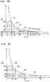
- the range satisfying the expression (1) is a left lower side of a curved line indicated in FIGs. 8A and 8B .
- eight areas 211 to 218 are set on the left lower side of the curved line.
- four areas 221 to 224 are set on the left lower side of the curved line.
- the area 211 indicated in FIG. 8A is an area in which the inner diameter (d) is not less than 5 ⁇ m and less than 20 ⁇ m, and the head difference (h) is not more than 664 mm.
- the inner diameter (d) is not less than 5 ⁇ m and less than 20 ⁇ m
- the head difference (h) is not more than 664 mm.
- the area 212 is an area in which the inner diameter (d) is not less than 20 ⁇ m and less than 30 ⁇ m, and the head difference (h) is not more than 443 mm.
- the inner diameter (d) is not less than 20 ⁇ m and less than 30 ⁇ m
- the expression (1) is satisfied and the meniscus formed in the opening of the nozzle 39 is maintained.
- the area 213 is an area in which the inner diameter (d) is not less than 30 ⁇ m and less than 50 ⁇ m, and the head difference (h) is not more than 266 mm.
- the inner diameter (d) is not less than 30 ⁇ m and less than 50 ⁇ m
- the expression (1) is satisfied and the meniscus formed in the opening of the nozzle 39 is maintained.
- the area 214 is an area in which the inner diameter (d) is not less than 50 ⁇ m and less than 80 ⁇ m, and the head difference (h) is not more than 166 mm.
- the inner diameter (d) is not less than 50 ⁇ m and less than 80 ⁇ m
- the expression (1) is satisfied and the meniscus formed in the opening of the nozzle 39 is maintained.
- the area 215 is an area in which the inner diameter (d) is not less than 80 ⁇ m and less than 90 ⁇ m, and the head difference (h) is not more than 148 mm.
- the inner diameter (d) is not less than 80 ⁇ m and less than 90 ⁇ m
- the expression (1) is satisfied and the meniscus formed in the opening of the nozzle 39 is maintained.
- the area 216 is an area in which the inner diameter (d) is not less than 90 ⁇ m and less than 100 ⁇ m, and the head difference (h) is not more than 133 mm.
- the inner diameter (d) is not less than 90 ⁇ m and less than 100 ⁇ m
- the expression (1) is satisfied and the meniscus formed in the opening of the nozzle 39 is maintained.
- the area 217 is an area in which the inner diameter (d) is not less than 100 ⁇ m and less than 110 ⁇ m, and the head difference (h) is not more than 121 mm.
- the inner diameter (d) is not less than 100 ⁇ m and less than 110 ⁇ m
- the expression (1) is satisfied and the meniscus formed in the opening of the nozzle 39 is maintained.
- the area 218 is an area in which the inner diameter (d) is not less than 110 ⁇ m and less than 120 ⁇ m, and the head difference (h) is not more than 111 mm.
- the inner diameter (d) is not less than 110 ⁇ m and less than 120 ⁇ m
- the expression (1) is satisfied and the meniscus formed in the opening of the nozzle 39 is maintained.
- the area 221 depicted in FIG. 8B is an area in which the inner diameter (d) is not less than 1 ⁇ m and less than 133 ⁇ m, and the head difference (h) is not more than 100mm.
- the expression (1) is satisfied and the meniscus formed in the opening of the nozzle 39 is maintained.
- the area 222 is an area in which the inner diameter (d) is not less than 1 ⁇ m and less than 66 ⁇ m, and the head difference (h) is greater than 100 mm and not more than 200 mm.
- the head difference (h) is greater than 100 mm and not more than 200 mm
- the expression (1) is satisfied and the meniscus formed in the opening of the nozzle 39 is maintained.
- the area 223 is an area in which the inner diameter (d) is not less than 1 ⁇ m and less than 33 ⁇ m, and the head difference (h) is greater than 200 mm and not more than 400 mm.
- the head difference (h) is greater than 200 mm and not more than 400 mm, by making the inner diameter (d) to be not less than 1 ⁇ m and less than 33 ⁇ m, the expression (1) is satisfied and the meniscus formed in the opening of the nozzle 39 is maintained.
- the area 224 is an area in which the inner diameter (d) is not less than 1 ⁇ m and less than 22 ⁇ m, and the head difference (h) is greater than 400 mm and not more than 600 mm.
- the head difference (h) is greater than 400 mm and not more than 600 mm
- the expression (1) is satisfied and the meniscus formed in the opening of the nozzle 39 is maintained.
- the reason by which the inner diameter (d) of the nozzle 39 is made to be not less than 1 ⁇ m is that if the inner diameter (d) is smaller than 1 ⁇ m, clogging of the ink may occur frequently.
- a condition for maintaining the meniscus formed in the opening of the nozzle 39 is as follows. That is: in a case that the inner diameter (d) is not less than 5 ⁇ m and less than 20 ⁇ m, the head difference (h) is required to be not more than 290 mm; in a case that the inner diameter (d) is not less than 20 ⁇ m and less than 30 ⁇ m, the head difference (h) is required to be not more than 193 mm; in a case that the inner diameter (d) is not less than 30 ⁇ m and less than 50 ⁇ m, the head difference (h) is required to be not more than 116 mm; in a case that the inner diameter (d) is not less than 50 ⁇ m and less than 80 ⁇ m, the head difference (h) is required to be not more than 73 mm; in a case that the inner diameter (d) is not less than 80 ⁇ m and less than 90 ⁇ m, the head difference (h) is required
- a condition for maintaining the meniscus formed in the opening of the nozzle 39 is as follows. That is: in a case that the head difference (h) is not more than 100mm, the inner diameter (d) is required to be not less than 1 ⁇ m and less than 58 ⁇ m; in a case that the head difference (h) is greater than 100 mm and not more than 200mm, the inner diameter (d) is required to be not less than 1 ⁇ m and less than 29 ⁇ m; in a case that the head difference (h) is greater than 200 mm and not more than 400mm, the inner diameter (d) is required to be not less than 1 ⁇ m and less than 14 ⁇ m; and in a case that the head difference (h) is greater than 400 mm and not more than 600mm, the inner diameter (d) is required to be not less than 1 ⁇ m and less than 9 ⁇ m.
- the specific weight ( ⁇ ) of the ink is not less than 1.03 g/cm 3 and not more than 1.13 g/cm 3
- the surface tension ( ⁇ ) of the ink is not less than 25 mN/m and not more than 37 mN/m
- the contact angle ⁇ defined between the inner surface of the nozzle and the ink is not less than 25° and not more than 50°
- the expression (1) is satisfied and the meniscus formed in the opening of the nozzle 39 is maintained, by determining the head difference (h) depending on the inner diameter (d), or by determining the inner diameter (d) depending on the head difference (h), in a similar manner as the case that the second condition is satisfied in the multifunction peripheral 10.
- the surface tension F2 acting upward on the ink in the vicinity of the opening of the nozzle 39 is made to be not less than the gravity F1 acting downward on the ink in the vicinity of the opening of the nozzle 39. Accordingly, in the state that the gas layer of the reservoir 80 is communicated with the outside, the meniscus of the nozzle 39 can be maintained.
- the inner diameter (d) of the nozzle 39 and the head difference (h) are determined under the condition that the maximum storable amount corresponds to the amount when the liquid surface LS of the ink 90 is coplanar with the upper end of the atmosphere opening port 88.
- the maximum storable amount can be set to be any amount not larger than the amount when the liquid surface LS of the ink 90 is coplanar with the upper end of the atmosphere opening port 88.
- the maximum storable amount may be set to be an amount not larger than the amount when the liquid surface LS of the ink 90 is coplanar with the upper end of the atmosphere opening port 88 and not smaller than the amount when the liquid surface LS of the ink 90 is positioned at the height of the mark.
- the inner diameter (d) of the nozzle 39 and the head difference (h) are determined based on the set maximum storable amount, and the position of the maximum liquid surface LS max corresponding to the set maximum storable amount.
- the mark may be formed to indicate the height of the ink surface corresponding to the indicated maximum storable amount to the user of the multifunction peripheral 10. Note that, the indicated maximum storable amount is different from the maximum storable amount used for determining the inner diameter (d) etc. For fail-safe design, the indicated maximum storable amount may be smaller than the maximum storable amount and the mark may be formed at a height lower than the maximum liquid surface LS max of the maximum storable amount.
- the recording part 24 may be provided with four reservoirs 80C, 80M, 80Y and 80B.
- a cyan ink (not depicted in the drawings) is stored in the reservoir 80C.
- a magenta ink (not depicted in the drawings) is stored in the reservoir 80M.
- a yellow ink (not depicted in the drawings) is stored in the reservoir 80Y.
- a black ink (not depicted in the drawings) is stored in the reservoir 80B.
- the reservoirs 80C, 80M, 80Y and 80B are arranged side by side in the left-right direction 9.
- the atmosphere opening port 88 is provided on each of the reservoirs 80C, 80M, 80Y and 80B. Note that the reservoirs 80C, 80M, 80Y and 80B may be arranged side by side in a direction different from the left-right direction 9, for example, in the front-rear direction 8.
- the order of arrangement of the reservoirs 80C, 80M, 80Y and 80B are not limited to the order depicted in FIG. 9 .
- the sizes of the respective reservoirs 80C, 80M, 80Y and 80B may be same as one another or different from one another.
- the system by which the head 38 records an image on the sheet 12 is of the serial head type in which the head 38 records the image on the sheet 12 while the head 38 is being moved by the carriage 40. It is allowable, however, that the system by which the head 38 records an image on the sheet 12 is of a line head type in which the recording part 24 is not provided with the carriage 40 and the head 38 records the image on the sheet 12 without moving.
- the head 38 is provided to span from the right end to the left end of the medium passing area.
- the conveying operation and the printing operation are executed in parallel and in a continuous manner. Namely, the ink droplets are continuously discharged from the nozzles 39 while the sheet 12 is (being) conveyed.
- the head 38 is supported by a frame of the casing 14.
- the reservoir 80 is installed in the carriage 40, and the ink is replenished by pouring the ink from the inlet port 83.
- the reservoir 80 is not limited to such a configuration.
- the reservoir 80 may be a cartridge which is attachable and detachable with respect to the carriage 40. In such a case, if the amount of the ink stored in the cartridge becomes small, or if the ink is used up, the cartridge is replaced by a new cartridge.
- the reservoir 80 is supported by the carriage 40, it is allowable that the reservoir 80 is not supported by the carriage 40.
- the reservoir 80 is arranged at a location, which is different from the carriage 40, in the multifunction peripheral 10.
- the reservoir 80 and the head 38 are connected to each other by a tube 151 (an example of a "liquid channel"); the ink 90 stored in the reservoir 80 is supplied to the head 38 via the tube 151, etc.
- at least a part of the reservoir 80 is located above the head 38.
- the carriage 40 moves while having the head 38 mounted thereon, the reservoir 80 is not mounted on the carriage 40, and the reservoir 80 and the head 38 are connected to each other by the tube 151, etc.
- an atmosphere communicating channel 161 (an example of a "gas channel") which is continued to the atmosphere opening port 88 is further provided on the upper wall 82 of the reservoir 80, as depicted in FIGs. 11A and 11B .
- the atmosphere communicating channel 161 is formed to have a groove shape in the upper wall 82 of the reservoir 80, and an upper side of the atmosphere communicating channel 161 is closed by a film 162.
- One end of the atmosphere communicating channel 161 is communicated with the gas layer of the reservoir 80 via an opening 163.
- the other end of the atmosphere communicating channel 161 is communicated with the outside via the atmosphere opening port 88 formed in the upper wall 82.
- the atmosphere communicating channel 161 has a labyrinth structure 164 which extends along the left-right direction 9 while repeating a U-turn in the front-rear direction 8.
- a semipermeable membrane 165 which closes the atmosphere opening port 88 is adhered to the atmosphere opening port 88 communicating with the other end of the atmosphere communicating channel 161.
- the semipermeable membrane 165 is a porous membrane having minute holes blocking passage of the ink and allowing passage of the gas.
- the semipermeable membrane 165 is formed of a fluorine resin (fluoro-resin) such as a polytetrafluoroethylene, a polychlorotrifluoroethylene, a tetrafluoroethylene-hexafluoropropylene copolymer, a tetrafluoroethylene-perfluoroalkyl vinyl ether copolymer, a tetrafluoroethylene-ethylene copolymer, etc.
- a fluorine resin fluoro-resin
- fluoro-resin such as a polytetrafluoroethylene, a polychlorotrifluoroethylene, a tetrafluoroethylene-hexafluoropropylene copolymer, a tetrafluoroethylene-perfluoroalkyl vinyl ether copolymer, a tetrafluoroethylene-ethylene copolymer, etc.
- the atmosphere communicating channel 161 may have a configuration having the semipermeable membrane 165 blocking the atmosphere opening port 88 but not having the labyrinth structure 164. As described above, the atmosphere communicating channel 161 may be configured to have at least either one of the labyrinth structure 164 and the semipermeable membrane 165.
- any valve unit is not provided on the atmosphere opening port 88, it is allowable that a valve unit is provided on the atmosphere opening port 88.
- the valve unit is configured to switch the gas layer of the reservoir 80 and the outside between a communicated state and a blocked state.
- the inner diameter (d) of the nozzle 39 and the head difference (h) are determined so as to satisfy the expression (1), the meniscus formed in the opening of the nozzle 39 is maintained in a case that the valve unit is in an opened state.
Landscapes
- Ink Jet (AREA)
- Particle Formation And Scattering Control In Inkjet Printers (AREA)
Abstract
Description
- The present invention relates to a liquid discharging apparatus having a head configured to discharge a liquid supplied from a reservoir.
- As an apparatus which discharges an ink stored in a tank from a nozzle so as to perform recording of an image, an ink-jet pen is known (see Patent Literature 1). In this ink-jet pen, a liquid surface of the ink stored in an ink cartridge is positioned above an opening of the nozzle. In the ink cartridge, a gas layer is not communicated with outside, or a valve is provided on a gas channel which communicates the gas layer to the outside.
- [Patent Literature 1] Japanese Patent Application Laid-Open No.
JP S55-65560 - In a case that the gas layer of the ink cartridge is not communicated with the outside and that the ink is consumed, the pressure of the gas layer is lowered. As a result, there is a fear that a meniscus formed in the opening of the nozzle might be broken or destroyed. Further, in a case that the valve, etc., is provided so as to maintain the pressure of the gas layer of the ink cartridge to be constant while communicating the gas layer with the outside, the structure of the ink-jet head might become complex, or the size of the ink-jet head might become great. On the other hand, in a case that the gas layer of the ink cartridge is always communicated with the outside, there is such a fear that the meniscus formed in the opening of the nozzle might be destroyed due to the head difference (waterhead difference).
- The present invention has been made in view of the above-described situation, and an object of the present invention is to provide means for maintaining the meniscus formed in the opening of the nozzle in a state that a reservoir in which a liquid is stored is communicated with the outside of the reservoir by an atmosphere port.
-
- (1) A liquid discharging apparatus of the present invention includes:
- a head having a nozzle configured to discharge a liquid;
- a reservoir configured to store the liquid such that the liquid has a liquid surface, and such that the liquid surface is positioned higher than an opening of the nozzle in a state that the reservoir stores the liquid of a maximum storable amount, the maximum storable amount being a maximum amount of the liquid capable of being stored in the reservoir; and
- an atmosphere port connecting a gas layer of the reservoir and outside of the reservoir.
- An inner diameter d of the nozzle and a head difference h satisfy the expression of phd / σcosθ ≤ 4 / g, provided that ρ is a specific weight of the liquid, σ is a surface tension of the liquid, θ is a contact angle of the liquid in the nozzle and g is gravitational acceleration, the head difference h being a difference in height between a meniscus formed in the opening of the nozzle and the liquid surface in the state that the reservoir stores the liquid of the maximum storable amount.
- According to the liquid discharging apparatus, the meniscus formed in the opening of the nozzle is maintained in a state that the reservoir in which the liquid is stored is communicated with the outside of the reservoir by the atmosphere port.
- (2) It is preferred that the inner diameter d is not less than 5 µm and is less than 20 µm; and
the head difference h is not more than 664 mm. - (3) It is preferred that the inner diameter d is not less than 20 µm and is less than 30 µm; and
the head difference h is not more than 443 mm. - (4) It is preferred that the inner diameter d is not less than 30 µm and is less than 50 µm; and
the head difference h is not more than 266 mm. - (5) It is preferred that the inner diameter d is not less than 50 µm and is less than 80 µm; and the head difference h is not more than 166 mm.
- (6) It is preferred that the inner diameter d is not less than 80 µm and is less than 90 µm; and
the head difference h is not more than 148 mm. - (7) It is preferred that the inner diameter d is not less than 90 µm and is less than 100 µm; and
the head difference h is not more than 133 mm. - (8) It is preferred that the inner diameter d is not less than 100 µm and is less than 110 µm; and
the head difference h is not more than 121 mm. - (9) It is preferred that the inner diameter d is not less than 110 µm and is less than 120 µm; and
the head difference h is not more than 111 mm. - (10) It is preferred that the inner diameter d is not less than 1 µm and is less than 133 µm; and
the head difference h is not more than 100 mm. - (11) It is preferred that the inner diameter d is not less than 1 µm and is less than 66 µm; and
the head difference h is greater than 100 mm and is not more than 200 mm. - (12) It is preferred that the inner diameter d is not less than 1 µm and is less than 33 µm; and
the head difference h is greater than 200 mm and is not more than 400 mm. - (13) It is preferred that the inner diameter d is not less than 1 µm and is less than 22 µm; and
the head difference h is greater than 400 mm and is not more than 600 mm. - (14) It is preferred that a viscosity of the liquid is not less than 2 cps and is less than 11 cps.
- (15) It is preferred that the liquid discharge apparatus further includes a carriage configured to move in a state that the head and the reservoir are mounted on the carriage.
- (16) It is preferred that the liquid discharging apparatus further includes a carriage configured to move in a state that the head is mounted on the carriage,
- wherein the reservoir is not mounted on the carriage; and
- the reservoir and the head are connected by a liquid channel.
- (17) It is preferred that the carriage is configured to move in a scanning direction; and
the head is configured to discharge the liquid in a case that the carriage is moving in the scanning direction. - (18) It is preferred that the liquid discharging apparatus further includes a gas channel continued to the atmosphere port,
wherein the gas channel has at least either one of a labyrinth structure and a semipermeable membrane. - According to the present invention, the meniscus formed in the opening of the nozzle is maintained in a state that the reservoir in which the liquid is stored is communicated with the outside of the reservoir by the atmosphere port.
-
-
FIG. 1 is a perspective view of a multifunction peripheral 10 as an example of an embodiment of the present invention. -
FIG. 2 is a vertical cross-sectional view schematically depicting the internal structure of aprinter part 11. -
FIG. 3 is a vertical cross-sectional view depicting a cross section of arecording part 24 as being cut by a plane orthogonal to a front-rear direction 8. -
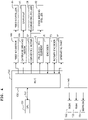
FIG. 4 is a functional block diagram of the multifunction peripheral 10. -
FIG. 5 is a flowchart for explaining image recording control by the multifunction peripheral 10. -
FIGs. 6A and 6B are each a view for explaining maintaining of a meniscus formed in an opening of anozzle 39, whereinFIG. 6A is a view schematically depicting areservoir 80 and thenozzle 39, andFIG. 6B is a view depicting a state that the meniscus is formed in the opening of thenozzle 39. -
FIG. 7 is a view depicting a range in which an inner diameter (d) and a head difference (h) satisfy an expression (1). -
FIGs. 8A and 8B are each a view depicting a specific example of the range in which the inner diameter (d) and the head difference (h) satisfy the expression (1), whereinFIG. 8A is a view depicting a range of the head difference (h) with respect to each of ranges of the inner diameter (d) andFIG. 8B is a view depicting a range of the inter diameter (d) with respect to each of ranges of the head difference (h). -
FIG. 9 is a vertical cross-sectional view of a cross section of arecording part 24, according to a modification, as being cut by a plane orthogonal to the front-rear direction 8. -
FIG. 10 is a schematic view indicating an arrangement position of areservoir 80 according to a modification. -
FIGs. 11A and 11B are each a perspective view depicting anupper wall 82 of areservoir 80 according to a modification, whereinFIG. 11A is a perspective view of a case that anatmosphere communicating channel 161 has alabyrinth structure 164, andFIG. 11B is a perspective view of a case that theatmosphere communicating channel 161 has thelabyrinth structure 164 and asemipermeable membrane 165. - In the following, an embodiment of the present invention will be explained. Note that the embodiment which is to be explained below is merely an example of the present invention; it is needless to say that the embodiment can be appropriately changed without changing the gist of the present invention. Further, in the following explanation, advancement or movement (progress) directed from a starting point to an end point of an arrow is expressed as an "orientation", and going forth and back on a line connecting the starting point and the end point of the arrow is expressed as a "direction". Furthermore, in the following description, an up-down
direction 7 is defined, with a state in which a multifunction peripheral 10 is operably installed (the state ofFig. 1 ) as the reference; a front-rear direction 8 is defined, with a side on which anopening 13 is provided being defined as afront surface 23; and a left-right direction 9 is defined, with the multifunction peripheral 10 as seen from the front side. The up-downdirection 7, the front-rear direction 8, and the left-right direction 9 are orthogonal to one another. - As depicted in
FIG. 1 , the multifunction peripheral 10 (an example of a "liquid discharging apparatus") has a casing (housing) 14 which has a substantially rectangular parallelepiped shape. Aprinter part 11 is provided at a lower part of thecasing 14. The multifunction peripheral 10 has a various kinds of functions such as a facsimile function, a print function, etc. The multifunction peripheral 10 has a function, as the print function, of recording an image on one surface of a sheet 12 (paper sheet 12; seeFIG. 2 ) in an ink-jet system. Note that the multifunction peripheral 10 may also be configured to record an image on both surfaces of thesheet 12. An operatingpart 17 is provided on an upper part of thecasing 14. The operatingpart 17 is constructed of a button configured to be operated for instructing the image recording, for performing a various kinds of settings, etc., a liquid crystal display configured to display a various kinds of information thereon, and the like. In the embodiment, the operatingpart 17 is constructed of a touch panel having both of the function of the button and the function of the liquid crystal display. - As depicted in
FIG. 2 , theprinter part 11 has afeed tray 20, a feedingpart 16, anouter guide member 18, aninner guide member 19, a conveyingroller pair 59, a dischargingroller pair 44, aplaten 42, arecording part 24, an encoder 35 (seeFIG. 4 ), a rotary encoder 75 (seeFIG. 4 ), a controller 130 (seeFIG. 4 ) and a memory 140 (seeFIG. 4 ) which are arranged inside thecasing 14. In the inside of thecasing 14, a various kinds of state sensors (not depicted in the drawings), which are configured to detect the state of the multifunction peripheral 10 and to output a signal in accordance with a result of detection, are arranged. - As depicted in
FIG. 1 , anopening 13 is formed in thefront surface 23 of theprinter part 11. Thefeed tray 20 is insertable and removable with respect to thecasing 14 via theopening 13, by moving in the front-rear direction 8. Thefeed tray 20 is movable between a feeding position (a position depicted inFIGs. 1 and2 ) at which thefeed tray 20 is installed in thecasing 14, and a non-feeding position at which thefeed tray 20 is removed (detached) from thecasing 14. Thefeed tray 20 is inserted rearward with respect to thecasing 14 to be moved to the feeding position, and thefeed tray 20 is pulled frontward with respect to thecasing 14 to be moved to the non-feeding position. - The
feed tray 20 is a member having a box-like shape of which upper part is opened, and is configured to store asheet 12. As depicted inFIG. 2 , a plurality of pieces of thesheet 12 are supported by abottom plate 22 of thefeed tray 20 in a state that thesheets 12 are overlaid on each other. Thedischarge tray 21 is arranged at a location which is above a front part of thefeed tray 20. Asheet 12 on which image recording has been performed by therecording part 24 and which is discharged is supported by an upper surface of thedischarge tray 21. In a case that thefeed tray 20 is at the feeding position, thesheet 12 supported by thefeed tray 20 is allowed to be fed to a conveyingroute 65. - As depicted in
FIG. 2 , the feedingpart 16 is arranged at a location below therecording part 24 and above thebottom plate 22 of thefeed tray 20. The feedingpart 16 is provided with a feedingroller 25, afeeding arm 26, adriving transmitting mechanism 27 and ashaft 28. The feedingroller 25 is supported rotatably at a forward end part of thefeeding arm 26. The feedingarm 26 rotates in a direction of anarrow 29, with theshaft 28 provided on a base part of thefeeding arm 26 as the center of rotation. With this, the feedingroller 25 is capable of making contact with and separating away from thefeed tray 20 or thesheet 12 which is supported by thefeed tray 20. - The feeding
roller 25 rotates by a driving force, of a feeding motor 102 (seeFIG. 4 ), which is transmitted to the feedingroller 25 by the drivingtransmitting mechanism 27 constructed of a plurality of gears meshed with each other. With this, among thesheets 12 supported by thebottom plate 22 of thefeed tray 20 at the feeding position, anuppermost sheet 12 which makes contact with the feedingroller 25 is fed to the conveyingroute 65. Note that the drivingtransmitting mechanism 27 is not limited to or restricted by the aspect in which the plurality of gears are meshed with each other; for example, the drivingtransmitting mechanism 27 may be a belt which is stretched or spanned between theshaft 28 and the shaft of the feedingroller 25. - As depicted in
FIG. 2 , the conveyingroute 65 is extended from a rear end part of thefeed tray 20. The conveyingroute 65 includes acurved part 33 and astraight part 34. Thecurved part 33 extends toward the upper side while making a U-turn from the rear side to the front side. Thestraight part 34 extends substantially along the front-rear direction 8. - The
curved part 33 is formed by theouter guide member 18 and theinner guide member 19 which face or are opposite to each other, with a predetermined spacing distance therebetween. Theouter guide member 18 and theinner guide member 19 are provided to extend in the left-right direction 9. At a position wherein therecording part 24 is arranged, thestraight part 34 is formed by therecording part 24 and theplaten 42 which face each other with a predetermined spacing distance therebetween. - The
sheet 12 supported by thefeed tray 20 is conveyed in thecurved part 33 by the feedingroller 25, and reaches the conveyingroller pair 59. Thesheet 12 pinched or held by the conveyingroller pair 59 is conveyed frontward in thestraight part 34 toward therecording part 24. Therecording part 24 records an image on thesheet 12 which has reached a location immediately below therecording part 24. Thesheet 12 having the image recorded thereon is conveyed frontward in thestraight part 34, and is discharged to thedischarge tray 21. As described above, thesheet 12 is conveyed along a conveyingorientation 15 which is indicated by an arrow of an alternate long and short dash line inFIG. 2 . - As depicted in
FIG. 2 , the conveyingroller pair 59 is arranged in thestraight part 34. The dischargingroller pair 44 is arranged, in thestraight part 34, on the downstream side in the conveyingorientation 15 with respect to the conveyingroller pair 59. - The conveying
roller pair 59 includes a conveyingroller 60 and apinch roller 61 which is arranged at a location below the conveyingroller 60 so as to face the conveyingroller 60. Thepinch roller 61 is pressed toward the conveyingroller 60 by an elastic member (not depicted in the drawings) such as a coil spring, etc. The conveyingroller pair 59 is capable of pinching or holding thesheet 12 therebetween. - The discharging
roller pair 44 includes a dischargingroller 62 and aspur roller 63 which is arranged at a location above the dischargingroller 62 so as to face the dischargingroller 62. Thespur roller 63 is pressed toward the dischargingroller 62 by an elastic member (not depicted in the drawings) such as a coil spring, etc. The dischargingroller pair 44 is capable of pinching or holding thesheet 12 therebetween. - The conveying
roller 60 and the dischargingroller 62 rotate in a case that a driving force is applied to the conveyingroller 60 and the dischargingroller 62 from the conveying motor 101 (seeFIG. 4 ). In a case that the conveyingroller 60 rotates in a state that thesheet 12 is pinched by the conveyingroller pair 59, thesheet 12 is conveyed in the conveyingorientation 15 by the conveyingroller pair 59, and is conveyed onto theplaten 42. In a case that the dischargingroller 62 rotates in a state that thesheet 12 is pinched by the dischargingroller pair 44, thesheet 12 is conveyed in the conveyingorientation 15 by the dischargingroller pair 44, and is discharged onto thedischarge tray 21. Note that a common motor may be used as the conveyingmotor 101 and the feedingmotor 102. In such a case, there is provided a configuration wherein a driving transmitting route from the common motor to each of the rollers is switchable. - Note that a mechanism or member configured to convey the
sheet 12 is not limited to the roller pairs as described above. For example, it is allowable that a conveying belt is arranged, instead of the conveyingroller pair 59 and the dischargingroller pair 44. - As depicted in
FIG. 2 , theplaten 42 is arranged in thestraight part 34 of the conveyingroute 65. Theplaten 42 faces therecording part 24 in the up-downdirection 7. Theplaten 42 supports thesheet 12 which is being conveyed in the conveyingroute 65 from therebelow. Thesheet 12 which is being conveyed in the conveyingroute 65 passes an area between a right end and a left end of theplaten 42 in the left-right direction 9 (hereinafter referred to as a "medium passing area"). - As depicted in
FIG. 2 , therecording part 24 is arranged at a location above theplaten 42 so as to face theplaten 42. Therecording part 24 is provided with acarriage 40, ahead 38 and a reservoir (storing part, storage) 80. - The
carriage 40 is supported to be movable in the left-right direction 9 (an example of a "scanning direction") which is orthogonal to the conveyingorientation 15, by twoguide rails rear direction 8 with a spacing distance therebetween. Thecarriage 40 is movable, in the left-right direction 9, between a position on the right side with respect to the medium passing area and a position on the left side with respect to the medium passing area. Note that the moving direction of thecarriage 40 is not limited to the left-right direction 9, and the moving direction may be a direction crossing the conveyingorientation 15. - The
guide rail 56 is arranged on the upstream side in the conveyingorientation 15 with respect to thehead 38. Theguide rail 57 is arranged on the downstream side in the conveyingorientation 15 with respect to thehead 38. The guide rails 56 and 57 are supported by a pair of side frames (not depicted in the drawings) which are arranged, in the left-right direction 9, at the outside of thestraight part 34 of the conveyingroute 65. Thecarriage 40 is moved in a case that a driving force is applied to thecarriage 40 from a carriage driving motor 103 (seeFIG. 4 ). - The encoder 35 (see
FIG. 4 ) is arranged in theguide rail 56 or theguide rail 57. Theencoder 35 includes an encoder strip extending in the left-right direction 9, and an optical sensor which is provided, on thecarriage 40, at a location facing the encoder strip. A pattern, in which light transmitting parts each configured to allow a light to transmit therethrough and light shielding parts each configured to shield the light are alternately arranged at an equal pitch in the left-right direction 9, is formed in the encoder strip. The optical sensor detects the light transmitting parts and the light shielding parts, thereby detecting a pulse signal. The pulse signal is a signal in accordance with the position in the left-right direction 9 of thecarriage 40. The pulse signal is outputted to the controller 130 (seeFIG. 4 ). - The
head 38 is supported by thecarriage 40. Alower surface 68 of thehead 38 is exposed downward, and faces theplaten 42. Thehead 38 is provided with a plurality ofnozzles 39, anink channel 37 and a piezoelectric element 45 (seeFIG. 4 ). - The plurality of
nozzles 39 are opened in thelower surface 68 of thehead 38. Theink channel 37 connects or links thereservoir 80 and the plurality ofnozzles 39. The piezoelectric element 45 (seeFIG. 4 ) deforms a part of theink channel 37 to thereby cause a droplet of an ink (ink droplet) to be discharged or ejected downward from thenozzles 39. Thepiezoelectric element 45 is driven or activated by an electric supply from the controller 130 (seeFIG. 4 ). In such a manner, thehead 38 has the plurality ofnozzles 39 which discharges or ejects an ink (an example of a "liquid"). - The
reservoir 80 is supported by thecarriage 40 in a state that thereservoir 80 is installed in thecarriage 40. Thereservoir 80 has aninternal space 81. Anink 90 is stored in theinternal space 81. In the present embodiment, therecording part 24 includes onereservoir 80. Anink 90 of the black color (black ink) is stored in this onereservoir 80. Note that the color of theink 90 stored in thereservoir 80 is not limited to the black color. - The
reservoir 80 is positioned above thehead 38. Note that, although the entirety of thereservoir 80 is located above thehead 38 in the present embodiment, it is also allowable that a part of thereservoir 80 is located above thehead 38, and another part, of thereservoir 80, which is different from the part is located at a height equal to or lower than the height of thehead 38. Theinternal space 81 of thereservoir 80 is communicated with the plurality ofnozzle 39 via theink channel 37. With this, theink 90 is suppled from theinternal space 81 to the plurality ofnozzles 39. - An
inlet port 83 via which theink 90 is poured or supplied to theinternal space 81 is provided in anupper wall 82 of thereservoir 80. Theinlet port 83 penetrates theupper wall 82 in a thickness direction of theupper wall 82 so as to communicate (connect) theinternal space 81 with the outside of thereservoir 80. A projected wall 84 (seeFIG. 3 ) is provided in a surrounding of theinlet port 83 in the upper surface of theupper wall 82. Alid 85 is fitted to the projectedwall 84, thereby closing theinlet port 83. In a case that thelid 85 is removed or detached from the projectedwall 84, theinlet port 83 is exposed to the outside. In this state, a bottle (not depicted in the drawings) is inserted into theinlet port 83, and theink 90 is poured from the bottle into theinternal space 81 via theinlet port 83. Note that theinlet port 83 may be provided at another position which is different from theupper wall 82, provided that at the another position, an upper part of theinternal space 81 is allowed to communicate with the outside. - As depicted in
FIG. 3 , an atmosphere opening port (atmosphere port) 88 is provided on theupper wall 82 of thereservoir 80. In theinternal space 81 of thereservoir 80, air enters into a part, of theinternal space 81, in which theink 90 is not present. The part, of theinternal space 81, into which the air has been entered is referred to as a gas layer. Theatmosphere opening port 88 communicates (connects) the gas layer of thereservoir 80 with the outside of thereservoir 80. - The
rotary encoder 75 depicted inFIG. 4 is constructed of an encoder disk which is provided on a shaft of the conveying motor 101 (seeFIG. 4 ) and which is configured to rotate together with the conveyingmotor 101, and an optical sensor. A pattern, in which transmitting parts each configured to allow a light to transmit therethrough and non-transmitting parts each configured not to allow the light transmit therethrough are alternately arranged at an equal pitch in a circumferential direction of the encoder disk, is formed in the encoder disk. In a case that the encoder disk rotates, a pulse signal is generated each time the transmitting part and the non-transmitting part are detected by the optical sensor. The generated pulse signal is outputted to the controller 130 (seeFIG. 4 ). Thecontroller 130 calculates a rotating amount of the conveyingmotor 101 based on the pulse signal. Note that therotary encoder 75 may be provided on a location which is different from the conveyingmotor 101, for example, on the feedingmotor 102, the conveyingroller 60, etc. - In the following, the configurations of the
controller 130 and thememory 140 will be explained, with reference toFIG. 4 . Thecontroller 130 is configured to control the entire operation of the multifunction peripheral 10. Thecontroller 130 is provided with aCPU 131 and anASIC 135. Thememory 140 is provided with aROM 132, aRAM 133 and anEEPROM 134. TheCPU 131, theASIC 135, theROM 132, theRAM 133 and theEEPROM 134 are connected to one another by aninternal bus 137. - The
ROM 132 stores therein a program for causing theCPU 131 to control a various kinds of operations, etc. TheRAM 133 is used as a storage area temporarily storing data and/or a signal to be used in a case that theCPU 131 executes the program, or as a working area for data processing. TheEEPROM 134 stores a setting and/or a flag, etc., to be held or stored even after the power source is switched off. - The conveying
motor 101, the feedingmotor 102 and thecarriage driving motor 103 are connected to theASIC 135. Driving circuit each of which controls one of the respective motors are installed in theASIC 135. TheCPU 131 outputs driving signals each of which is for rotating one of the respective motors to one of the driving circuits corresponding to one of the respective motors. Each of the driving circuits outputs a driving current, in accordance with the driving signal obtained from theCPU 131, to one of the motors corresponding thereto. With this, the corresponding motor is rotated. Namely, thecontroller 130 controls the feedingmotor 102 to cause the feedingpart 16 to feed thesheet 12. Further, thecontroller 130 controls the conveyingmotor 101 to cause the conveyingroller pair 59 and the dischargingroller pair 44 to convey thesheet 12. Furthermore, thecontroller 130 controls thecarriage driving motor 103 to move thecarriage 40. - Moreover, the optical sensor of the
rotary encoder 75 is connected to theASIC 135. Thecontroller 130 calculates the rotating amount of the conveyingmotor 101 based on the electric signal received from the optical sensor of therotary encoder 75. Further, theencoder 35 is connected to theASIC 135. Thecontroller 130 recognizes the position of thecarriage 40 and/or the presence or absence of the movement of thecarriage 40, based on the pulse signal received from theencoder 35. - Further, the
piezoelectric element 45 is connected to theASIC 135. Thepiezoelectric element 45 is driven or activated by the electric supply from thecontroller 130 via a non-illustrated drive circuit. Thecontroller 130 controls the electric supply to thepiezoelectric element 45 so as to selectively discharge or eject an ink droplet from the plurality ofnozzles 39. Furthermore, a state sensor (not depicted in the drawings) is connected to theASIC 135. Thecontroller 130 performs an image recording processing, an abnormality processing, etc., which will be described later on, based on a signal received from the state sensor. - In a case that the
controller 130 performs recording of an image on thesheet 12, thecontroller 130 alternately executes a conveying processing and a printing processing. The conveying processing is a processing of causing the conveyingroller pair 59 and the dischargingroller pair 44 to convey thesheet 12 only by a predetermined line feed amount. Thecontroller 130 controls the conveyingmotor 101 to thereby cause the conveyingroller pair 59 and the dischargingroller pair 44 to execute the conveying processing. The printing processing is a processing of controlling the electric supply to thepiezoelectric element 45 while moving thecarriage 40 along the left-right direction 9 to thereby cause thehead 38 to discharge the ink droplet from thenozzle 39. During the printing processing, thecarriage 40 is positioned in the medium passing area (an area between the right end and the left end of the platen 42), and faces or is opposite to theplaten 42. - During a period of time (time interval) between the conveying processing which is currently being executed (current conveying processing) and the conveying processing which is to be executed next (a next conveying processing), the
controller 130 stops thesheet 12 for a predetermined period of time. Further, thecontroller 130 executes the printing processing during the period of time for which thesheet 12 is stopped. Namely, in the printing processing, thecontroller 130 executes one pass for causing the ink droplets to be discharged from thenozzles 39 while causing thecarriage 40 to move leftward or rightward. With this, an image recording for the one pass is executed with respect to thesheet 12. - The
controller 130 is capable of recording an image on an entire area, of thesheet 12, in which an image is recordable, by alternately and repeatedly executing the conveying processing and the printing processing. Namely, thecontroller 130 records an image on one piece of thesheet 12 with a plurality of passes (a pass performed for a plurality of times). In such a manner, in the multifunction peripheral 10, thecarriage 40 moves with thehead 38 and thereservoir 80 mounted thereon. Thecarriage 40 moves in the left-right direction 9, and thehead 38 discharges the ink(s) while thecarriage 40 is moving in the left-right direction 9. - Note that the
controller 130 is not limited to or restricted by thecontroller 130 as described above. Thecontroller 130 may be configured such that only theCPU 131 performs the various kinds of processing or that only theASIC 135 performs the various kinds of processing, or that theCPU 131 and theASIC 135 perform the various kinds of processing in a cooperative manner. Alternatively, thecontroller 130 may be configured such that oneCPU 131 singly performs the processing, or that a plurality of pieces of theCPU 131 perform the processing in a sharing manner. Still alternatively, thecontroller 130 may be configured such that oneASIC 135 singly performs the processing, or that a plurality of pieces of theASIC 135 perform the processing in a sharing manner. - In the
printer part 11 configured as described above, a series of image recording controls by which thesheet 12 is conveyed and an image is recorded on the conveyedsheet 12 is executed by thecontroller 130. In the following, the image recording control by thecontroller 130 will be explained, with reference to a flowchart depicted inFIG. 5 . - In a case that the image recording control is not executed, the
carriage 40 is located at the outside of the medium passing area in the left-right direction 9 (this position is referred to as a "maintenance position"), and thecarriage 40 does not face theplaten 42. - A print command is transmitted, to the
controller 130, from the operating part 17 (seeFIG. 1 ) of the multifunction peripheral 10 and/or an external apparatus or device connected to the multifunction peripheral 10. The print command includes a command of starting the image recording control, information regarding the size of thesheet 12, and print data of image recording to be performed on thesheet 12. - In a case that the
controller 130 obtains the print command (step S10: YES), thecontroller 130 executes feeding of asheet 12 supported by the feed tray 20 (step S20). - In step S20, the
controller 130 drives the feedingmotor 102. With this, the feedingroller 25 feeds thesheet 12 supported by thefeed tray 20 to the conveyingroute 65. Further, thecontroller 130 drives the conveyingmotor 101. With this, in a case that a forward end of thesheet 12 fed to the conveyingroute 65 by the feedingroller 25 reaches the conveyingroller pair 59, the conveyingroller pair 59 conveys thesheet 12 in the conveyingorientation 15. - Next, the
controller 130 drives thecarriage driving motor 103 to thereby move thecarriage 40 from the maintenance position to a start position. The start position is a moving start position of thecarriage 40 in a case that the printing processing (step S30) is executed, and is determined based on the print data. In step S20, a feeding operation of thesheet 12 and a moving operation of thecarriage 40 are executed in parallel. - Next, the
controller 130 executes the printing processing (step S30). In the printing processing in step S30, thecontroller 130 executes one pass. Namely, thecontroller 130 causes the ink droplets to be discharged from thenozzles 39, while moving thecarriage 40 to move from the start position. Note that, it is allowable that thecarriage 40 which has started moving from the maintenance position in step S20 does not stop at the start position, and keeps moving for the print processing. Of course, it is allowable that thecarriage 40 temporarily stops at the start position. - Next, the
controller 130 determines whether or not the image recording on acurrent sheet 12 is ended, based on the information regarding the size of thesheet 12 and/or the print data included in the print command (step S40). - In a case that, in step S40, the image recording on the
current sheet 12 is not ended (step S40: NO), the conveying processing is executed (step S50). In the conveying processing in step S50, thecontroller 130 drives the conveyingmotor 101 to thereby cause the conveyingroller pair 59 and the dischargingroller pair 44 to convey thesheet 12 by a predetermined line feed amount. Afterwards, the control by thecontroller 130 proceeds to step S30. - In step S40, in a case that the image recording on the
current sheet 12 is ended (step S40: YES), thecontroller 130 causes the conveyingroller pair 59 and the dischargingroller pair 44 to convey thesheet 12 in the conveyingorientation 15 to thereby discharge thesheet 12 to the discharge tray 21 (step S60). - Next, the
controller 130 determines whether or not there still is image data which is included in the print command and which has not been recorded on thesheet 12, namely, whether or not there is image recording to be performed on a next page (step S70). - In a case that there is image recording to be performed on the next page (step S70: YES), the control by the
controller 130 proceeds to step S20. In this case, thecontroller 130 feeds a succeedingsheet 12 from thefeed tray 20 to the conveying route 65 (step S20). Note that the feeding of the succeeding sheet 12 (step S20) may be executed in parallel with the discharging of the preceding sheet 12 (step S60). In a case that there is not any image recording to be performed on the next page (step S70: NO), thecontroller 130 ends the series of image recording controls. - Note that although a case that the
controller 130 performs the image recording normally has been explained here, it is also allowable that thecontroller 130 executes a processing of detecting an abnormality and a processing to be executed in a case that an abnormality has been detected (each of these processing is not depicted in the drawings), while performing the image recording. - In the following, regarding a case that the multifunction peripheral 10 performs the image recording, a condition for maintaining the meniscus of the
nozzle 39 of thehead 38 will be explained. InFIG. 6A , thereservoir 80 and thenozzle 39 are schematically depicted. Although one piece of thenozzle 39 is depicted inFIG. 6A in order that the drawings are easily understood, the plurality ofnozzles 39 are actually present. - As depicted in
FIG. 6A , theink 90 is stored in thereservoir 80 while forming a liquid surface LS. InFIG. 6A , the liquid surface LS when theink 90 of a maximum storable amount (that is, a maximum amount of theink 90 storable in the reservoir 80) is stored in thereservoir 80 is depicted by dotted line with the reference sign of LSmax. In the present embodiment, the maximum storable amount corresponds to an amount when theink 90 fills theinternal space 81 and the liquid surface LS of theink 90 is coplanar with the upper end of the atmosphere opening port 88 (orupper surface 80u of the reservoir 80). In a case that theink 90 of the maxim storable amount is stored in thereservoir 80, the height of the liquid surface LS is located above the opening of the nozzle 39 (that is, located at a position higher than the position of the opening of the nozzle 39). Theatmosphere opening port 88 communicates (connects) the gas layer of the reservoir 80 (a part, in theinternal space 81, in which theink 90 is not present) and the outside. - As depicted in
FIG. 6B , a meniscus having a downwardly projected or convex shape is formed by theink 90 in the opening of thenozzle 39. A gravity F1 acting downward and a surface tension F2 acting upward due to a contact between theink 90 and the inner surface of thenozzle 39 act on theink 90 in the vicinity of the opening of thenozzle 39. In a case that the surface tension F2 is not less than the gravity F1, the meniscus formed in the opening of thenozzle 39 is maintained. - It is provided that: an inner diameter of the
nozzle 39 is (d), a head difference (waterhead difference) which is a difference in height between the meniscus (that is, the position of the base portion of the meniscus, or the position of the opening of the nozzle 39) formed in the opening of thenozzle 39 and the liquid surface LS in the maxim amount (maximum storable amount) of theink 90 storable in thereservoir 80 is (h), a specific weight (specific gravity) of theink 90 is (ρ), a surface tension of theink 90 is (σ), a contact angle defined between theink 90 and the inner surface of thenozzle 39 is (θ), and gravitational acceleration is (g). The gravity F1 acting downward on the ink in the vicinity of the opening of thenozzle 39 is given by: πd2 / 4 x pgh. The surface tension F2 acting upward on the ink in the vicinity of the opening of thenozzle 39 is given by: πdσcosθ. In a case that these formulae are substituted for and arranged in a relational expression: F1 ≤ F2, the following expression (1) is obtained:
- In the multifunction peripheral 10, in a case that the specific weight (ρ) of the
ink 90, the surface tension (σ) of theink 90, the contact angle (θ) defined between theink 90 and the inner surface of thenozzle 39 are provided, the inner diameter (d) of thenozzle 39 and the head difference (h) are determined so as to satisfy the expression (1). In a case that the inner diameter (d) is made to be the horizontal axis and that the head difference (h) is made to be the vertical axis, a range satisfying the expression (1) is a left lower side (hatched part) of a curved line indicated inFIG. 7 . In a case that the combination of the value of the inner diameter (d) and the value of the head difference (h) is in the inside of the hatched part indicated inFIG. 7 , the meniscus formed in the opening of thenozzle 39 is maintained. - In the following, a specific example of the range in which the inner diameter (d) of the
nozzle 39 and the head difference (h) satisfy the expression (1) will be explained. The viscosity of the ink used in a printer of the ink-jet system, such as the multifunction peripheral 10, etc., is, for example, not less than 2 cps and less than 11 cps. As the ink, for example, a water-based ink which contains not less than 50% and not more than 70% of water is used. The specific weight (ρ) of the ink is, for example, not less than 1.03 g/cm3 and not more than 1.13 g/cm3. The surface tension σ of the ink is, for example, not less than 25 mN/m and not more than 37 mN/m. The contact angle (θ) defined between the inner surface of the nozzle and the ink is, for example, not less than 25° and not more than 50°. - The surface tension (σ) of the ink is obtained, for example, by using the Wilhelmy method. The contact angle (θ) defined between the inner surface of the nozzle and the ink is obtained by measuring a contact angle defined in a case of dripping the ink onto a plate formed of a same material as that of the nozzle by, for example, using the θ/2 method (half-angle method).
- In the following, a set of conditions of "the specific weight (ρ) of the ink is 1.03 g/cm3", "the surface tension (σ) of the ink is 37 mN/m" and "the contact angle (θ) defined between the inner surface of the nozzle and the ink is 25°" is referred to as a "first condition", and a set of conditions of "the specific weight (ρ) of the ink is 1.13 g/cm3", "the surface tension (σ) of the ink is 25 mN/m" and "the contact angle (θ) defined between the inner surface of the nozzle and the ink is 50°" is referred to as a "second condition".
- In a case that the first condition is satisfied in the multifunction peripheral 10, the range satisfying the expression (1) is a left lower side of a curved line indicated in
FIGs. 8A and 8B . As indicated inFIG 8A , eightareas 211 to 218 are set on the left lower side of the curved line. As indicated inFIG. 8B , fourareas 221 to 224 are set on the left lower side of the curved line. In a case that the combination of the value of the inner diameter (d) and the value of the head difference (h) is within any one of theareas 211 to 218 and theareas 221 to 224, the expression (1) is satisfied and the meniscus formed in the opening of thenozzle 39 is maintained. - The
area 211 indicated inFIG. 8A is an area in which the inner diameter (d) is not less than 5 µm and less than 20 µm, and the head difference (h) is not more than 664 mm. In a case that the inner diameter (d) is not less than 5 µm and less than 20 µm, by making the head difference (h) to be not more than 664 mm, the expression (1) is satisfied and the meniscus formed in the opening of thenozzle 39 is maintained - The
area 212 is an area in which the inner diameter (d) is not less than 20 µm and less than 30 µm, and the head difference (h) is not more than 443 mm. In a case that the inner diameter (d) is not less than 20 µm and less than 30 µm, by making the head difference (h) to be not more than 443 mm, the expression (1) is satisfied and the meniscus formed in the opening of thenozzle 39 is maintained. - The
area 213 is an area in which the inner diameter (d) is not less than 30 µm and less than 50 µm, and the head difference (h) is not more than 266 mm. In a case that the inner diameter (d) is not less than 30 µm and less than 50 µm, by making the head difference (h) to be not more than 266 mm, the expression (1) is satisfied and the meniscus formed in the opening of thenozzle 39 is maintained. - The
area 214 is an area in which the inner diameter (d) is not less than 50 µm and less than 80 µm, and the head difference (h) is not more than 166 mm. In a case that the inner diameter (d) is not less than 50 µm and less than 80 µm, by making the head difference (h) to be not more than 166 mm, the expression (1) is satisfied and the meniscus formed in the opening of thenozzle 39 is maintained. - The
area 215 is an area in which the inner diameter (d) is not less than 80 µm and less than 90 µm, and the head difference (h) is not more than 148 mm. In a case that the inner diameter (d) is not less than 80 µm and less than 90 µm, by making the head difference (h) to be not more than 148 mm, the expression (1) is satisfied and the meniscus formed in the opening of thenozzle 39 is maintained. - The
area 216 is an area in which the inner diameter (d) is not less than 90 µm and less than 100 µm, and the head difference (h) is not more than 133 mm. In a case that the inner diameter (d) is not less than 90 µm and less than 100 µm, by making the head difference (h) to be not more than 133 mm, the expression (1) is satisfied and the meniscus formed in the opening of thenozzle 39 is maintained. - The
area 217 is an area in which the inner diameter (d) is not less than 100 µm and less than 110 µm, and the head difference (h) is not more than 121 mm. In a case that the inner diameter (d) is not less than 100 µm and less than 110 µm, by making the head difference (h) to be not more than 121 mm, the expression (1) is satisfied and the meniscus formed in the opening of thenozzle 39 is maintained. - The
area 218 is an area in which the inner diameter (d) is not less than 110 µm and less than 120 µm, and the head difference (h) is not more than 111 mm. In a case that the inner diameter (d) is not less than 110 µm and less than 120 µm, by making the head difference (h) to be not more than 111 mm, the expression (1) is satisfied and the meniscus formed in the opening of thenozzle 39 is maintained. - The
area 221 depicted inFIG. 8B is an area in which the inner diameter (d) is not less than 1 µm and less than 133 µm, and the head difference (h) is not more than 100mm. In a case that the head difference (h) is not more than 100 mm, by making the inner diameter (d) to be not less than 1 µm and less than 133 µm, the expression (1) is satisfied and the meniscus formed in the opening of thenozzle 39 is maintained. - The
area 222 is an area in which the inner diameter (d) is not less than 1 µm and less than 66 µm, and the head difference (h) is greater than 100 mm and not more than 200 mm. In a case that the head difference (h) is greater than 100 mm and not more than 200 mm, by making the inner diameter (d) to be not less than 1 µm and less than 66 µm, the expression (1) is satisfied and the meniscus formed in the opening of thenozzle 39 is maintained. - The
area 223 is an area in which the inner diameter (d) is not less than 1 µm and less than 33 µm, and the head difference (h) is greater than 200 mm and not more than 400 mm. In a case that the head difference (h) is greater than 200 mm and not more than 400 mm, by making the inner diameter (d) to be not less than 1 µm and less than 33 µm, the expression (1) is satisfied and the meniscus formed in the opening of thenozzle 39 is maintained. - The
area 224 is an area in which the inner diameter (d) is not less than 1 µm and less than 22 µm, and the head difference (h) is greater than 400 mm and not more than 600 mm. In a case that the head difference (h) is greater than 400 mm and not more than 600 mm, by making the inner diameter (d) to be not less than 1 µm and less than 22 µm, the expression (1) is satisfied and the meniscus formed in the opening of thenozzle 39 is maintained. Note that the reason by which the inner diameter (d) of thenozzle 39 is made to be not less than 1 µm is that if the inner diameter (d) is smaller than 1 µm, clogging of the ink may occur frequently. - In a case that the second condition is satisfied in the multifunction peripheral 10, a condition for maintaining the meniscus formed in the opening of the
nozzle 39 is as follows. That is: in a case that the inner diameter (d) is not less than 5 µm and less than 20 µm, the head difference (h) is required to be not more than 290 mm; in a case that the inner diameter (d) is not less than 20 µm and less than 30 µm, the head difference (h) is required to be not more than 193 mm; in a case that the inner diameter (d) is not less than 30 µm and less than 50 µm, the head difference (h) is required to be not more than 116 mm; in a case that the inner diameter (d) is not less than 50 µm and less than 80 µm, the head difference (h) is required to be not more than 73 mm; in a case that the inner diameter (d) is not less than 80 µm and less than 90 µm, the head difference (h) is required to be not more than 64 mm; in a case that the inner diameter (d) is not less than 90 µm and less than 100 µm, the head difference (h) is required to be not more than 58 mm; in a case that the inner diameter (d) is not less than 100 µm and less than 110 µm, the head difference (h) is required to be not more than 53 mm; and in a case that the inner diameter (d) is not less than 110 µm and less than 120 µm, the head difference (h) is required to be not more than 48 mm. - In a case that the second condition is satisfied in the multifunction peripheral 10, a condition for maintaining the meniscus formed in the opening of the
nozzle 39 is as follows. That is: in a case that the head difference (h) is not more than 100mm, the inner diameter (d) is required to be not less than 1 µm and less than 58 µm; in a case that the head difference (h) is greater than 100 mm and not more than 200mm, the inner diameter (d) is required to be not less than 1 µm and less than 29 µm; in a case that the head difference (h) is greater than 200 mm and not more than 400mm, the inner diameter (d) is required to be not less than 1 µm and less than 14 µm; and in a case that the head difference (h) is greater than 400 mm and not more than 600mm, the inner diameter (d) is required to be not less than 1 µm and less than 9 µm. - In a case that in the multifunction peripheral 10, the specific weight (ρ) of the ink is not less than 1.03 g/cm3 and not more than 1.13 g/cm3, the surface tension (σ) of the ink is not less than 25 mN/m and not more than 37 mN/m, and the contact angle θ defined between the inner surface of the nozzle and the ink is not less than 25° and not more than 50°, the expression (1) is satisfied and the meniscus formed in the opening of the
nozzle 39 is maintained, by determining the head difference (h) depending on the inner diameter (d), or by determining the inner diameter (d) depending on the head difference (h), in a similar manner as the case that the second condition is satisfied in the multifunction peripheral 10. - According to the present embodiment, since the inner diameter (d) of the
nozzle 39 and the head difference (h) satisfy the expression (1), the surface tension F2 acting upward on the ink in the vicinity of the opening of thenozzle 39 is made to be not less than the gravity F1 acting downward on the ink in the vicinity of the opening of thenozzle 39. Accordingly, in the state that the gas layer of thereservoir 80 is communicated with the outside, the meniscus of thenozzle 39 can be maintained. - In the above-describe embodiment, the inner diameter (d) of the
nozzle 39 and the head difference (h) are determined under the condition that the maximum storable amount corresponds to the amount when the liquid surface LS of theink 90 is coplanar with the upper end of theatmosphere opening port 88. However, there is no limitation thereto. The maximum storable amount can be set to be any amount not larger than the amount when the liquid surface LS of theink 90 is coplanar with the upper end of theatmosphere opening port 88. - For example, in a case that any mark (for example. drawn line, projection, and the like) is formed (on a
sidewall 80s of thereservoir 80, for example), the maximum storable amount may be set to be an amount not larger than the amount when the liquid surface LS of theink 90 is coplanar with the upper end of theatmosphere opening port 88 and not smaller than the amount when the liquid surface LS of theink 90 is positioned at the height of the mark. In such a case, the inner diameter (d) of thenozzle 39 and the head difference (h) are determined based on the set maximum storable amount, and the position of the maximum liquid surface LSmax corresponding to the set maximum storable amount. - The mark may be formed to indicate the height of the ink surface corresponding to the indicated maximum storable amount to the user of the multifunction peripheral 10. Note that, the indicated maximum storable amount is different from the maximum storable amount used for determining the inner diameter (d) etc. For fail-safe design, the indicated maximum storable amount may be smaller than the maximum storable amount and the mark may be formed at a height lower than the maximum liquid surface LSmax of the maximum storable amount.
- In the above-described embodiment, although only one piece of the
reservoir 80 is provided on therecording part 24, it is allowable that a plurality ofreservoirs 80 are provided on therecording part 24. For example, as depicted inFIG. 9 , therecording part 24 may be provided with fourreservoirs - A cyan ink (not depicted in the drawings) is stored in the
reservoir 80C. A magenta ink (not depicted in the drawings) is stored in thereservoir 80M. A yellow ink (not depicted in the drawings) is stored in thereservoir 80Y. A black ink (not depicted in the drawings) is stored in thereservoir 80B. Thereservoirs right direction 9. Theatmosphere opening port 88 is provided on each of thereservoirs reservoirs right direction 9, for example, in the front-rear direction 8. Further, the order of arrangement of thereservoirs FIG. 9 . Furthermore, the sizes of therespective reservoirs - In the above-described embodiment, the system by which the
head 38 records an image on thesheet 12 is of the serial head type in which thehead 38 records the image on thesheet 12 while thehead 38 is being moved by thecarriage 40. It is allowable, however, that the system by which thehead 38 records an image on thesheet 12 is of a line head type in which therecording part 24 is not provided with thecarriage 40 and thehead 38 records the image on thesheet 12 without moving. In the case of the line head type, thehead 38 is provided to span from the right end to the left end of the medium passing area. Further, the conveying operation and the printing operation are executed in parallel and in a continuous manner. Namely, the ink droplets are continuously discharged from thenozzles 39 while thesheet 12 is (being) conveyed. Further, in the case of the line head type, thehead 38 is supported by a frame of thecasing 14. - In the embodiment, the
reservoir 80 is installed in thecarriage 40, and the ink is replenished by pouring the ink from theinlet port 83. Thereservoir 80, however, is not limited to such a configuration. For example, thereservoir 80 may be a cartridge which is attachable and detachable with respect to thecarriage 40. In such a case, if the amount of the ink stored in the cartridge becomes small, or if the ink is used up, the cartridge is replaced by a new cartridge. - In the embodiment, although the
reservoir 80 is supported by thecarriage 40, it is allowable that thereservoir 80 is not supported by thecarriage 40. For example, as depicted inFIG. 10 , it is allowable that thereservoir 80 is arranged at a location, which is different from thecarriage 40, in the multifunction peripheral 10. In such a case, thereservoir 80 and thehead 38 are connected to each other by a tube 151 (an example of a "liquid channel"); theink 90 stored in thereservoir 80 is supplied to thehead 38 via thetube 151, etc. In this case also, at least a part of thereservoir 80 is located above thehead 38. In this modification, thecarriage 40 moves while having thehead 38 mounted thereon, thereservoir 80 is not mounted on thecarriage 40, and thereservoir 80 and thehead 38 are connected to each other by thetube 151, etc. - In the embodiment, although only the
atmosphere opening port 88 is provided on theupper wall 82 of thereservoir 80, it is allowable that an atmosphere communicating channel 161 (an example of a "gas channel") which is continued to theatmosphere opening port 88 is further provided on theupper wall 82 of thereservoir 80, as depicted inFIGs. 11A and 11B . - In an example depicted in
FIG. 11A , theatmosphere communicating channel 161 is formed to have a groove shape in theupper wall 82 of thereservoir 80, and an upper side of theatmosphere communicating channel 161 is closed by afilm 162. One end of theatmosphere communicating channel 161 is communicated with the gas layer of thereservoir 80 via anopening 163. The other end of theatmosphere communicating channel 161 is communicated with the outside via theatmosphere opening port 88 formed in theupper wall 82. Theatmosphere communicating channel 161 has alabyrinth structure 164 which extends along the left-right direction 9 while repeating a U-turn in the front-rear direction 8. - In an example depicted in
FIG. 11B , asemipermeable membrane 165 which closes theatmosphere opening port 88 is adhered to theatmosphere opening port 88 communicating with the other end of theatmosphere communicating channel 161. Thesemipermeable membrane 165 is a porous membrane having minute holes blocking passage of the ink and allowing passage of the gas. For example, thesemipermeable membrane 165 is formed of a fluorine resin (fluoro-resin) such as a polytetrafluoroethylene, a polychlorotrifluoroethylene, a tetrafluoroethylene-hexafluoropropylene copolymer, a tetrafluoroethylene-perfluoroalkyl vinyl ether copolymer, a tetrafluoroethylene-ethylene copolymer, etc. With this, theink 90 stored in theinternal space 81 of thereservoir 80 is blocked by thesemipermeable membrane 165, and thus does not outflow to the outside of thereservoir 80 via theatmosphere communicating channel 161 and theatmosphere opening port 88. On the other hand, the air is capable of freely moving between the gas layer of thereservoir 80 and the outside. - The
atmosphere communicating channel 161 may have a configuration having thesemipermeable membrane 165 blocking theatmosphere opening port 88 but not having thelabyrinth structure 164. As described above, theatmosphere communicating channel 161 may be configured to have at least either one of thelabyrinth structure 164 and thesemipermeable membrane 165. - In the embodiment, although any valve unit is not provided on the
atmosphere opening port 88, it is allowable that a valve unit is provided on theatmosphere opening port 88. The valve unit is configured to switch the gas layer of thereservoir 80 and the outside between a communicated state and a blocked state. In this modification, in a case that the inner diameter (d) of thenozzle 39 and the head difference (h) are determined so as to satisfy the expression (1), the meniscus formed in the opening of thenozzle 39 is maintained in a case that the valve unit is in an opened state. - 10: multifunction peripheral (liquid discharging apparatus), 38: head, 39: nozzle, 40 carriage, 80 reservoir, 88 atmosphere opening port (atmosphere port), 90: ink (liquid), 151: tube (liquid channel), 161: atmosphere communicating channel (gas channel), 164: labyrinth structure, 165: semipermeable membrane
Claims (15)
- A liquid discharging apparatus comprising:a head having a nozzle configured to discharge a liquid;a reservoir configured to store the liquid such that the liquid has a liquid surface, and such that the liquid surface is positioned higher than an opening of the nozzle in a state that the reservoir stores the liquid of a maximum storable amount, the maximum storable amount being a maximum amount of the liquid capable of being stored in the reservoir; andan atmosphere port connecting a gas layer of the reservoir and outside of the reservoir,wherein an inner diameter d of the nozzle and a head difference h satisfy the expression of phd / σcosθ ≤ 4 / g, provided that ρ is a specific weight of the liquid, σ is a surface tension of the liquid, θ is a contact angle of the liquid in the nozzle and g is gravitational acceleration, the head difference h being a difference in height between a meniscus formed in the opening of the nozzle and the liquid surface in the state that the reservoir stores the liquid of the maximum storable amount.
- The liquid discharging apparatus according to claim 1, wherein the inner diameter d is not less than 5 µm and is less than 20 µm; and
the head difference h is not more than 664 mm. - The liquid discharging apparatus according to claim 1, wherein the inner diameter d is not less than 20 µm and is less than 30 µm; and
the head difference h is not more than 443 mm. - The liquid discharging apparatus according to claim 1, wherein the inner diameter d is not less than 30 µm and is less than 50 µm; and
the head difference h is not more than 266 mm. - The liquid discharging apparatus according to claim 1, wherein the inner diameter d is not less than 50 µm and is less than 80 µm; and
the head difference h is not more than 166 mm. - The liquid discharging apparatus according to claim 1, wherein the inner diameter d is not less than 80 µm and is less than 90 µm; and
the head difference h is not more than 148 mm. - The liquid discharging apparatus according to claim 1, wherein the inner diameter d is not less than 90 µm and is less than 100 µm; and
the head difference h is not more than 133 mm. - The liquid discharging apparatus according to claim 1, wherein the inner diameter d is not less than 100 µm and is less than 110 µm; and
the head difference h is not more than 121 mm. - The liquid discharging apparatus according to claim 1, wherein the inner diameter d is not less than 110 µm and is less than 120 µm; and
the head difference h is not more than 111 mm. - The liquid discharging apparatus according to claim 1, wherein the inner diameter d is not less than 1 µm and is less than 133 µm; and
the head difference h is not more than 100 mm. - The liquid discharging apparatus according to claim 1, wherein the inner diameter d is not less than 1 µm and is less than 66 µm; and
the head difference h is greater than 100 mm and is not more than 200 mm. - The liquid discharging apparatus according to claim 1, wherein the inner diameter d is not less than 1 µm and is less than 33 µm; and
the head difference h is greater than 200 mm and is not more than 400 mm. - The liquid discharging apparatus according to claim 1, wherein the inner diameter d is not less than 1 µm and is less than 22 µm; and
the head difference h is greater than 400 mm and is not more than 600 mm. - The liquid discharging apparatus according to any one of claims 1 to 13, wherein a viscosity of the liquid is not less than 2 cps and is less than 11 cps.
- The liquid discharging apparatus according to any one of claims 1 to 14, further comprising a carriage configured to move in a state that the head and the reservoir are mounted on the carriage.
Applications Claiming Priority (1)
| Application Number | Priority Date | Filing Date | Title |
|---|---|---|---|
| JP2021053838A JP7676870B2 (en) | 2021-03-26 | 2021-03-26 | liquid discharge device |
Publications (2)
| Publication Number | Publication Date |
|---|---|
| EP4063131A1 true EP4063131A1 (en) | 2022-09-28 |
| EP4063131B1 EP4063131B1 (en) | 2024-10-23 |
Family
ID=80933794
Family Applications (1)
| Application Number | Title | Priority Date | Filing Date |
|---|---|---|---|
| EP22164165.7A Active EP4063131B1 (en) | 2021-03-26 | 2022-03-24 | Liquid discharging apparatus |
Country Status (4)
| Country | Link |
|---|---|
| US (1) | US12202271B2 (en) |
| EP (1) | EP4063131B1 (en) |
| JP (1) | JP7676870B2 (en) |
| CN (1) | CN115122777B (en) |
Citations (5)
| Publication number | Priority date | Publication date | Assignee | Title |
|---|---|---|---|---|
| JPS5565560A (en) | 1978-11-10 | 1980-05-17 | Yokogawa Hokushin Electric Corp | Ink jet pen |
| JP2000334965A (en) * | 1999-05-28 | 2000-12-05 | Ricoh Co Ltd | Nozzle forming member, inkjet head, and method of manufacturing nozzle forming member |
| JP2004122760A (en) * | 2002-08-01 | 2004-04-22 | Konica Minolta Holdings Inc | Inkjet recorder |
| JP2006315232A (en) * | 2005-05-11 | 2006-11-24 | Konica Minolta Holdings Inc | Liquid ejector |
| JP2008246785A (en) * | 2007-03-29 | 2008-10-16 | Fujifilm Corp | Nozzle plate and liquid discharge device |
Family Cites Families (16)
| Publication number | Priority date | Publication date | Assignee | Title |
|---|---|---|---|---|
| JPH0781079A (en) * | 1993-09-20 | 1995-03-28 | Canon Inc | Inkjet recording device |
| US5745138A (en) * | 1996-05-16 | 1998-04-28 | Ostermeier; Bruce H. | Ink chamber with pressure relief chamber having pressure relief aperture and microparticles to exert capilliary action on ink |
| US6461812B2 (en) * | 1998-09-09 | 2002-10-08 | Agilent Technologies, Inc. | Method and multiple reservoir apparatus for fabrication of biomolecular arrays |
| JP2000168103A (en) | 1998-12-10 | 2000-06-20 | Toshiba Tec Corp | Driving method and driving device for inkjet head |
| JP4277551B2 (en) * | 2002-07-26 | 2009-06-10 | ブラザー工業株式会社 | PRESSURE GENERATOR, INK JET PRINTER EQUIPPED WITH THE PRESSURE GENERATOR, AND METHOD FOR CONTROLLING AIR PUMP DRIVE MOTOR OF PRESSURE GENERATOR |
| US6908167B2 (en) | 2002-08-01 | 2005-06-21 | Konica Corporation | Ink-jet recording apparatus |
| JP2005161635A (en) | 2003-12-02 | 2005-06-23 | Canon Inc | Ink tank and ink supply device |
| JP4441336B2 (en) * | 2004-06-11 | 2010-03-31 | 日本碍子株式会社 | Manufacturing method of microarray |
| JP4105135B2 (en) * | 2004-08-30 | 2008-06-25 | シャープ株式会社 | Ink jet head device, ink jet device, and ink supply method for ink jet head device |
| US7845784B2 (en) * | 2006-12-28 | 2010-12-07 | Kabushiki Kaisha Toshiba | Ink supplying mechanism and ink supplying method |
| JP2010149456A (en) | 2008-12-26 | 2010-07-08 | Jit Kk | Ink storage container |
| JP2010234615A (en) * | 2009-03-31 | 2010-10-21 | Brother Ind Ltd | Liquid container |
| JP6528478B2 (en) * | 2015-03-12 | 2019-06-12 | セイコーエプソン株式会社 | tank |
| US20170087850A1 (en) * | 2015-09-25 | 2017-03-30 | Dover Europe Sàrl | Passive Meniscus Pressure Stabilization During Shutdown Of An Ink Jet Printing System |
| CN109318596B (en) | 2017-07-31 | 2021-04-30 | 兄弟工业株式会社 | Liquid consumption device and liquid consumption system |
| JP7035649B2 (en) * | 2018-03-13 | 2022-03-15 | 株式会社リコー | Droplet forming device and droplet forming method |
-
2021
- 2021-03-26 JP JP2021053838A patent/JP7676870B2/en active Active
-
2022
- 2022-03-24 EP EP22164165.7A patent/EP4063131B1/en active Active
- 2022-03-25 US US17/704,570 patent/US12202271B2/en active Active
- 2022-03-25 CN CN202210299420.9A patent/CN115122777B/en active Active
Patent Citations (5)
| Publication number | Priority date | Publication date | Assignee | Title |
|---|---|---|---|---|
| JPS5565560A (en) | 1978-11-10 | 1980-05-17 | Yokogawa Hokushin Electric Corp | Ink jet pen |
| JP2000334965A (en) * | 1999-05-28 | 2000-12-05 | Ricoh Co Ltd | Nozzle forming member, inkjet head, and method of manufacturing nozzle forming member |
| JP2004122760A (en) * | 2002-08-01 | 2004-04-22 | Konica Minolta Holdings Inc | Inkjet recorder |
| JP2006315232A (en) * | 2005-05-11 | 2006-11-24 | Konica Minolta Holdings Inc | Liquid ejector |
| JP2008246785A (en) * | 2007-03-29 | 2008-10-16 | Fujifilm Corp | Nozzle plate and liquid discharge device |
Also Published As
| Publication number | Publication date |
|---|---|
| US12202271B2 (en) | 2025-01-21 |
| EP4063131B1 (en) | 2024-10-23 |
| JP7676870B2 (en) | 2025-05-15 |
| US20220305799A1 (en) | 2022-09-29 |
| JP2022150983A (en) | 2022-10-07 |
| CN115122777B (en) | 2026-04-14 |
| CN115122777A (en) | 2022-09-30 |
Similar Documents
| Publication | Publication Date | Title |
|---|---|---|
| EP3351391B1 (en) | Recording apparatus | |
| US9108410B2 (en) | Printing apparatus and control method | |
| CN115413259A (en) | inkjet recording device | |
| US12017451B2 (en) | Inkjet recording device including controller controlling valve to close air communication opening formed in ink storage portion in case of occurrence of abnormality | |
| JP7204462B2 (en) | Ink supply system and inkjet printer | |
| JP7388487B2 (en) | image recording device | |
| EP4063131B1 (en) | Liquid discharging apparatus | |
| EP2605912B1 (en) | Image forming apparatus | |
| JP7306839B2 (en) | inkjet printer | |
| JP7183786B2 (en) | Controller and program | |
| JP5299099B2 (en) | Inkjet recording head unit and inkjet recording apparatus | |
| US11865847B2 (en) | Liquid discharge apparatus | |
| JP7043443B2 (en) | Cap unit status determination method for inkjet printers and inkjet printers | |
| JP7215167B2 (en) | Controller and program | |
| JP7729082B2 (en) | liquid discharge device | |
| EP4124458A1 (en) | Liquid ejecting device and liquid reservoir | |
| JP7707599B2 (en) | Image Recording Device | |
| JP2023046474A (en) | Liquid discharge device | |
| JP2022184305A (en) | Liquid ejector | |
| JP2022151116A (en) | Liquid ejector | |
| JP2023015578A (en) | Ink jet printer | |
| JP2020108921A (en) | Control device |
Legal Events
| Date | Code | Title | Description |
|---|---|---|---|
| PUAI | Public reference made under article 153(3) epc to a published international application that has entered the european phase |
Free format text: ORIGINAL CODE: 0009012 |
|
| STAA | Information on the status of an ep patent application or granted ep patent |
Free format text: STATUS: THE APPLICATION HAS BEEN PUBLISHED |
|
| AK | Designated contracting states |
Kind code of ref document: A1 Designated state(s): AL AT BE BG CH CY CZ DE DK EE ES FI FR GB GR HR HU IE IS IT LI LT LU LV MC MK MT NL NO PL PT RO RS SE SI SK SM TR |
|
| STAA | Information on the status of an ep patent application or granted ep patent |
Free format text: STATUS: REQUEST FOR EXAMINATION WAS MADE |
|
| 17P | Request for examination filed |
Effective date: 20230322 |
|
| RBV | Designated contracting states (corrected) |
Designated state(s): AL AT BE BG CH CY CZ DE DK EE ES FI FR GB GR HR HU IE IS IT LI LT LU LV MC MK MT NL NO PL PT RO RS SE SI SK SM TR |
|
| P01 | Opt-out of the competence of the unified patent court (upc) registered |
Effective date: 20230529 |
|
| GRAP | Despatch of communication of intention to grant a patent |
Free format text: ORIGINAL CODE: EPIDOSNIGR1 |
|
| STAA | Information on the status of an ep patent application or granted ep patent |
Free format text: STATUS: GRANT OF PATENT IS INTENDED |
|
| INTG | Intention to grant announced |
Effective date: 20240712 |
|
| GRAS | Grant fee paid |
Free format text: ORIGINAL CODE: EPIDOSNIGR3 |
|
| GRAA | (expected) grant |
Free format text: ORIGINAL CODE: 0009210 |
|
| STAA | Information on the status of an ep patent application or granted ep patent |
Free format text: STATUS: THE PATENT HAS BEEN GRANTED |
|
| AK | Designated contracting states |
Kind code of ref document: B1 Designated state(s): AL AT BE BG CH CY CZ DE DK EE ES FI FR GB GR HR HU IE IS IT LI LT LU LV MC MK MT NL NO PL PT RO RS SE SI SK SM TR |
|
| REG | Reference to a national code |
Ref country code: GB Ref legal event code: FG4D |
|
| REG | Reference to a national code |
Ref country code: CH Ref legal event code: EP |
|
| REG | Reference to a national code |
Ref country code: DE Ref legal event code: R096 Ref document number: 602022006957 Country of ref document: DE |
|
| REG | Reference to a national code |
Ref country code: IE Ref legal event code: FG4D |
|
| REG | Reference to a national code |
Ref country code: LT Ref legal event code: MG9D |
|
| REG | Reference to a national code |
Ref country code: NL Ref legal event code: MP Effective date: 20241023 |
|
| REG | Reference to a national code |
Ref country code: AT Ref legal event code: MK05 Ref document number: 1734542 Country of ref document: AT Kind code of ref document: T Effective date: 20241023 |
|
| PG25 | Lapsed in a contracting state [announced via postgrant information from national office to epo] |
Ref country code: NL Free format text: LAPSE BECAUSE OF FAILURE TO SUBMIT A TRANSLATION OF THE DESCRIPTION OR TO PAY THE FEE WITHIN THE PRESCRIBED TIME-LIMIT Effective date: 20241023 |
|
| PG25 | Lapsed in a contracting state [announced via postgrant information from national office to epo] |
Ref country code: NL Free format text: LAPSE BECAUSE OF FAILURE TO SUBMIT A TRANSLATION OF THE DESCRIPTION OR TO PAY THE FEE WITHIN THE PRESCRIBED TIME-LIMIT Effective date: 20241023 |
|
| PG25 | Lapsed in a contracting state [announced via postgrant information from national office to epo] |
Ref country code: HR Free format text: LAPSE BECAUSE OF FAILURE TO SUBMIT A TRANSLATION OF THE DESCRIPTION OR TO PAY THE FEE WITHIN THE PRESCRIBED TIME-LIMIT Effective date: 20241023 Ref country code: PT Free format text: LAPSE BECAUSE OF FAILURE TO SUBMIT A TRANSLATION OF THE DESCRIPTION OR TO PAY THE FEE WITHIN THE PRESCRIBED TIME-LIMIT Effective date: 20250224 Ref country code: IS Free format text: LAPSE BECAUSE OF FAILURE TO SUBMIT A TRANSLATION OF THE DESCRIPTION OR TO PAY THE FEE WITHIN THE PRESCRIBED TIME-LIMIT Effective date: 20250223 |
|
| PG25 | Lapsed in a contracting state [announced via postgrant information from national office to epo] |
Ref country code: FI Free format text: LAPSE BECAUSE OF FAILURE TO SUBMIT A TRANSLATION OF THE DESCRIPTION OR TO PAY THE FEE WITHIN THE PRESCRIBED TIME-LIMIT Effective date: 20241023 |
|
| PG25 | Lapsed in a contracting state [announced via postgrant information from national office to epo] |
Ref country code: BG Free format text: LAPSE BECAUSE OF FAILURE TO SUBMIT A TRANSLATION OF THE DESCRIPTION OR TO PAY THE FEE WITHIN THE PRESCRIBED TIME-LIMIT Effective date: 20241023 |
|
| PG25 | Lapsed in a contracting state [announced via postgrant information from national office to epo] |
Ref country code: ES Free format text: LAPSE BECAUSE OF FAILURE TO SUBMIT A TRANSLATION OF THE DESCRIPTION OR TO PAY THE FEE WITHIN THE PRESCRIBED TIME-LIMIT Effective date: 20241023 |
|
| PG25 | Lapsed in a contracting state [announced via postgrant information from national office to epo] |
Ref country code: NO Free format text: LAPSE BECAUSE OF FAILURE TO SUBMIT A TRANSLATION OF THE DESCRIPTION OR TO PAY THE FEE WITHIN THE PRESCRIBED TIME-LIMIT Effective date: 20250123 |
|
| PG25 | Lapsed in a contracting state [announced via postgrant information from national office to epo] |
Ref country code: LV Free format text: LAPSE BECAUSE OF FAILURE TO SUBMIT A TRANSLATION OF THE DESCRIPTION OR TO PAY THE FEE WITHIN THE PRESCRIBED TIME-LIMIT Effective date: 20241023 Ref country code: AT Free format text: LAPSE BECAUSE OF FAILURE TO SUBMIT A TRANSLATION OF THE DESCRIPTION OR TO PAY THE FEE WITHIN THE PRESCRIBED TIME-LIMIT Effective date: 20241023 Ref country code: GR Free format text: LAPSE BECAUSE OF FAILURE TO SUBMIT A TRANSLATION OF THE DESCRIPTION OR TO PAY THE FEE WITHIN THE PRESCRIBED TIME-LIMIT Effective date: 20250124 |
|
| PG25 | Lapsed in a contracting state [announced via postgrant information from national office to epo] |
Ref country code: PL Free format text: LAPSE BECAUSE OF FAILURE TO SUBMIT A TRANSLATION OF THE DESCRIPTION OR TO PAY THE FEE WITHIN THE PRESCRIBED TIME-LIMIT Effective date: 20241023 |
|
| PG25 | Lapsed in a contracting state [announced via postgrant information from national office to epo] |
Ref country code: RS Free format text: LAPSE BECAUSE OF FAILURE TO SUBMIT A TRANSLATION OF THE DESCRIPTION OR TO PAY THE FEE WITHIN THE PRESCRIBED TIME-LIMIT Effective date: 20250123 |
|
| PG25 | Lapsed in a contracting state [announced via postgrant information from national office to epo] |
Ref country code: SM Free format text: LAPSE BECAUSE OF FAILURE TO SUBMIT A TRANSLATION OF THE DESCRIPTION OR TO PAY THE FEE WITHIN THE PRESCRIBED TIME-LIMIT Effective date: 20241023 |
|
| PG25 | Lapsed in a contracting state [announced via postgrant information from national office to epo] |
Ref country code: DK Free format text: LAPSE BECAUSE OF FAILURE TO SUBMIT A TRANSLATION OF THE DESCRIPTION OR TO PAY THE FEE WITHIN THE PRESCRIBED TIME-LIMIT Effective date: 20241023 |
|
| PG25 | Lapsed in a contracting state [announced via postgrant information from national office to epo] |
Ref country code: EE Free format text: LAPSE BECAUSE OF FAILURE TO SUBMIT A TRANSLATION OF THE DESCRIPTION OR TO PAY THE FEE WITHIN THE PRESCRIBED TIME-LIMIT Effective date: 20241023 |
|
| PG25 | Lapsed in a contracting state [announced via postgrant information from national office to epo] |
Ref country code: RO Free format text: LAPSE BECAUSE OF FAILURE TO SUBMIT A TRANSLATION OF THE DESCRIPTION OR TO PAY THE FEE WITHIN THE PRESCRIBED TIME-LIMIT Effective date: 20241023 |
|
| REG | Reference to a national code |
Ref country code: DE Ref legal event code: R097 Ref document number: 602022006957 Country of ref document: DE |
|
| PG25 | Lapsed in a contracting state [announced via postgrant information from national office to epo] |
Ref country code: SK Free format text: LAPSE BECAUSE OF FAILURE TO SUBMIT A TRANSLATION OF THE DESCRIPTION OR TO PAY THE FEE WITHIN THE PRESCRIBED TIME-LIMIT Effective date: 20241023 |
|
| PG25 | Lapsed in a contracting state [announced via postgrant information from national office to epo] |
Ref country code: CZ Free format text: LAPSE BECAUSE OF FAILURE TO SUBMIT A TRANSLATION OF THE DESCRIPTION OR TO PAY THE FEE WITHIN THE PRESCRIBED TIME-LIMIT Effective date: 20241023 |
|
| PG25 | Lapsed in a contracting state [announced via postgrant information from national office to epo] |
Ref country code: IT Free format text: LAPSE BECAUSE OF FAILURE TO SUBMIT A TRANSLATION OF THE DESCRIPTION OR TO PAY THE FEE WITHIN THE PRESCRIBED TIME-LIMIT Effective date: 20241023 |
|
| PLBE | No opposition filed within time limit |
Free format text: ORIGINAL CODE: 0009261 |
|
| STAA | Information on the status of an ep patent application or granted ep patent |
Free format text: STATUS: NO OPPOSITION FILED WITHIN TIME LIMIT |
|
| PG25 | Lapsed in a contracting state [announced via postgrant information from national office to epo] |
Ref country code: SE Free format text: LAPSE BECAUSE OF FAILURE TO SUBMIT A TRANSLATION OF THE DESCRIPTION OR TO PAY THE FEE WITHIN THE PRESCRIBED TIME-LIMIT Effective date: 20241023 |
|
| 26N | No opposition filed |
Effective date: 20250724 |
|
| PG25 | Lapsed in a contracting state [announced via postgrant information from national office to epo] |
Ref country code: MC Free format text: LAPSE BECAUSE OF FAILURE TO SUBMIT A TRANSLATION OF THE DESCRIPTION OR TO PAY THE FEE WITHIN THE PRESCRIBED TIME-LIMIT Effective date: 20241023 |
|
| REG | Reference to a national code |
Ref country code: CH Ref legal event code: H13 Free format text: ST27 STATUS EVENT CODE: U-0-0-H10-H13 (AS PROVIDED BY THE NATIONAL OFFICE) Effective date: 20251024 |
|
| PG25 | Lapsed in a contracting state [announced via postgrant information from national office to epo] |
Ref country code: LU Free format text: LAPSE BECAUSE OF NON-PAYMENT OF DUE FEES Effective date: 20250324 |
|
| REG | Reference to a national code |
Ref country code: BE Ref legal event code: MM Effective date: 20250331 |
|
| PG25 | Lapsed in a contracting state [announced via postgrant information from national office to epo] |
Ref country code: BE Free format text: LAPSE BECAUSE OF NON-PAYMENT OF DUE FEES Effective date: 20250331 |
|
| PG25 | Lapsed in a contracting state [announced via postgrant information from national office to epo] |
Ref country code: CH Free format text: LAPSE BECAUSE OF NON-PAYMENT OF DUE FEES Effective date: 20250331 |
|
| PG25 | Lapsed in a contracting state [announced via postgrant information from national office to epo] |
Ref country code: IE Free format text: LAPSE BECAUSE OF NON-PAYMENT OF DUE FEES Effective date: 20250324 |
|
| PGFP | Annual fee paid to national office [announced via postgrant information from national office to epo] |
Ref country code: GB Payment date: 20260211 Year of fee payment: 5 |
|
| PGFP | Annual fee paid to national office [announced via postgrant information from national office to epo] |
Ref country code: DE Payment date: 20260213 Year of fee payment: 5 |
|
| PGFP | Annual fee paid to national office [announced via postgrant information from national office to epo] |
Ref country code: FR Payment date: 20260209 Year of fee payment: 5 |
|
| PG25 | Lapsed in a contracting state [announced via postgrant information from national office to epo] |
Ref country code: CY Free format text: LAPSE BECAUSE OF FAILURE TO SUBMIT A TRANSLATION OF THE DESCRIPTION OR TO PAY THE FEE WITHIN THE PRESCRIBED TIME-LIMIT Effective date: 20241023 |
|
| PG25 | Lapsed in a contracting state [announced via postgrant information from national office to epo] |
Ref country code: LT Free format text: LAPSE BECAUSE OF FAILURE TO SUBMIT A TRANSLATION OF THE DESCRIPTION OR TO PAY THE FEE WITHIN THE PRESCRIBED TIME-LIMIT Effective date: 20241023 |
|
| PG25 | Lapsed in a contracting state [announced via postgrant information from national office to epo] |
Ref country code: TR Free format text: LAPSE BECAUSE OF FAILURE TO SUBMIT A TRANSLATION OF THE DESCRIPTION OR TO PAY THE FEE WITHIN THE PRESCRIBED TIME-LIMIT Effective date: 20241023 |