EP4063059A1 - Foreign substance capturing apparatus and electrical steel sheet manufacturing facility comprising same - Google Patents
Foreign substance capturing apparatus and electrical steel sheet manufacturing facility comprising same Download PDFInfo
- Publication number
- EP4063059A1 EP4063059A1 EP20888835.4A EP20888835A EP4063059A1 EP 4063059 A1 EP4063059 A1 EP 4063059A1 EP 20888835 A EP20888835 A EP 20888835A EP 4063059 A1 EP4063059 A1 EP 4063059A1
- Authority
- EP
- European Patent Office
- Prior art keywords
- magnetic
- capturing device
- foreign object
- object capturing
- nonmagnetic
- Prior art date
- Legal status (The legal status is an assumption and is not a legal conclusion. Google has not performed a legal analysis and makes no representation as to the accuracy of the status listed.)
- Pending
Links
Images



Classifications
-
- B—PERFORMING OPERATIONS; TRANSPORTING
- B01—PHYSICAL OR CHEMICAL PROCESSES OR APPARATUS IN GENERAL
- B01D—SEPARATION
- B01D46/00—Filters or filtering processes specially modified for separating dispersed particles from gases or vapours
- B01D46/0027—Filters or filtering processes specially modified for separating dispersed particles from gases or vapours with additional separating or treating functions
- B01D46/0034—Filters or filtering processes specially modified for separating dispersed particles from gases or vapours with additional separating or treating functions using magnetic forces to remove particles
-
- B—PERFORMING OPERATIONS; TRANSPORTING
- B23—MACHINE TOOLS; METAL-WORKING NOT OTHERWISE PROVIDED FOR
- B23K—SOLDERING OR UNSOLDERING; WELDING; CLADDING OR PLATING BY SOLDERING OR WELDING; CUTTING BY APPLYING HEAT LOCALLY, e.g. FLAME CUTTING; WORKING BY LASER BEAM
- B23K26/00—Working by laser beam, e.g. welding, cutting or boring
- B23K26/36—Removing material
- B23K26/362—Laser etching
- B23K26/364—Laser etching for making a groove or trench, e.g. for scribing a break initiation groove
-
- B—PERFORMING OPERATIONS; TRANSPORTING
- B03—SEPARATION OF SOLID MATERIALS USING LIQUIDS OR USING PNEUMATIC TABLES OR JIGS; MAGNETIC OR ELECTROSTATIC SEPARATION OF SOLID MATERIALS FROM SOLID MATERIALS OR FLUIDS; SEPARATION BY HIGH-VOLTAGE ELECTRIC FIELDS
- B03C—MAGNETIC OR ELECTROSTATIC SEPARATION OF SOLID MATERIALS FROM SOLID MATERIALS OR FLUIDS; SEPARATION BY HIGH-VOLTAGE ELECTRIC FIELDS
- B03C1/00—Magnetic separation
- B03C1/02—Magnetic separation acting directly on the substance being separated
- B03C1/035—Open gradient magnetic separators, i.e. separators in which the gap is unobstructed, characterised by the configuration of the gap
-
- B—PERFORMING OPERATIONS; TRANSPORTING
- B03—SEPARATION OF SOLID MATERIALS USING LIQUIDS OR USING PNEUMATIC TABLES OR JIGS; MAGNETIC OR ELECTROSTATIC SEPARATION OF SOLID MATERIALS FROM SOLID MATERIALS OR FLUIDS; SEPARATION BY HIGH-VOLTAGE ELECTRIC FIELDS
- B03C—MAGNETIC OR ELECTROSTATIC SEPARATION OF SOLID MATERIALS FROM SOLID MATERIALS OR FLUIDS; SEPARATION BY HIGH-VOLTAGE ELECTRIC FIELDS
- B03C1/00—Magnetic separation
- B03C1/02—Magnetic separation acting directly on the substance being separated
- B03C1/28—Magnetic plugs and dipsticks
- B03C1/284—Magnetic plugs and dipsticks with associated cleaning means, e.g. retractable non-magnetic sleeve
-
- B—PERFORMING OPERATIONS; TRANSPORTING
- B03—SEPARATION OF SOLID MATERIALS USING LIQUIDS OR USING PNEUMATIC TABLES OR JIGS; MAGNETIC OR ELECTROSTATIC SEPARATION OF SOLID MATERIALS FROM SOLID MATERIALS OR FLUIDS; SEPARATION BY HIGH-VOLTAGE ELECTRIC FIELDS
- B03C—MAGNETIC OR ELECTROSTATIC SEPARATION OF SOLID MATERIALS FROM SOLID MATERIALS OR FLUIDS; SEPARATION BY HIGH-VOLTAGE ELECTRIC FIELDS
- B03C1/00—Magnetic separation
- B03C1/02—Magnetic separation acting directly on the substance being separated
- B03C1/28—Magnetic plugs and dipsticks
- B03C1/286—Magnetic plugs and dipsticks disposed at the inner circumference of a recipient, e.g. magnetic drain bolt
-
- B—PERFORMING OPERATIONS; TRANSPORTING
- B08—CLEANING
- B08B—CLEANING IN GENERAL; PREVENTION OF FOULING IN GENERAL
- B08B15/00—Preventing escape of dirt or fumes from the area where they are produced; Collecting or removing dirt or fumes from that area
- B08B15/04—Preventing escape of dirt or fumes from the area where they are produced; Collecting or removing dirt or fumes from that area from a small area, e.g. a tool
-
- B—PERFORMING OPERATIONS; TRANSPORTING
- B23—MACHINE TOOLS; METAL-WORKING NOT OTHERWISE PROVIDED FOR
- B23K—SOLDERING OR UNSOLDERING; WELDING; CLADDING OR PLATING BY SOLDERING OR WELDING; CUTTING BY APPLYING HEAT LOCALLY, e.g. FLAME CUTTING; WORKING BY LASER BEAM
- B23K26/00—Working by laser beam, e.g. welding, cutting or boring
- B23K26/08—Devices involving relative movement between laser beam and workpiece
- B23K26/083—Devices involving movement of the workpiece in at least one axial direction
- B23K26/0838—Devices involving movement of the workpiece in at least one axial direction by using an endless conveyor belt
-
- B—PERFORMING OPERATIONS; TRANSPORTING
- B23—MACHINE TOOLS; METAL-WORKING NOT OTHERWISE PROVIDED FOR
- B23K—SOLDERING OR UNSOLDERING; WELDING; CLADDING OR PLATING BY SOLDERING OR WELDING; CUTTING BY APPLYING HEAT LOCALLY, e.g. FLAME CUTTING; WORKING BY LASER BEAM
- B23K26/00—Working by laser beam, e.g. welding, cutting or boring
- B23K26/12—Working by laser beam, e.g. welding, cutting or boring in a special environment or atmosphere, e.g. in an enclosure
- B23K26/127—Working by laser beam, e.g. welding, cutting or boring in a special environment or atmosphere, e.g. in an enclosure in an enclosure
-
- B—PERFORMING OPERATIONS; TRANSPORTING
- B23—MACHINE TOOLS; METAL-WORKING NOT OTHERWISE PROVIDED FOR
- B23K—SOLDERING OR UNSOLDERING; WELDING; CLADDING OR PLATING BY SOLDERING OR WELDING; CUTTING BY APPLYING HEAT LOCALLY, e.g. FLAME CUTTING; WORKING BY LASER BEAM
- B23K26/00—Working by laser beam, e.g. welding, cutting or boring
- B23K26/16—Removal of by-products, e.g. particles or vapours produced during treatment of a workpiece
-
- B—PERFORMING OPERATIONS; TRANSPORTING
- B23—MACHINE TOOLS; METAL-WORKING NOT OTHERWISE PROVIDED FOR
- B23K—SOLDERING OR UNSOLDERING; WELDING; CLADDING OR PLATING BY SOLDERING OR WELDING; CUTTING BY APPLYING HEAT LOCALLY, e.g. FLAME CUTTING; WORKING BY LASER BEAM
- B23K26/00—Working by laser beam, e.g. welding, cutting or boring
- B23K26/36—Removing material
- B23K26/40—Removing material taking account of the properties of the material involved
-
- B—PERFORMING OPERATIONS; TRANSPORTING
- B03—SEPARATION OF SOLID MATERIALS USING LIQUIDS OR USING PNEUMATIC TABLES OR JIGS; MAGNETIC OR ELECTROSTATIC SEPARATION OF SOLID MATERIALS FROM SOLID MATERIALS OR FLUIDS; SEPARATION BY HIGH-VOLTAGE ELECTRIC FIELDS
- B03C—MAGNETIC OR ELECTROSTATIC SEPARATION OF SOLID MATERIALS FROM SOLID MATERIALS OR FLUIDS; SEPARATION BY HIGH-VOLTAGE ELECTRIC FIELDS
- B03C2201/00—Details of magnetic or electrostatic separation
- B03C2201/20—Magnetic separation of bulk or dry particles in mixtures
-
- B—PERFORMING OPERATIONS; TRANSPORTING
- B03—SEPARATION OF SOLID MATERIALS USING LIQUIDS OR USING PNEUMATIC TABLES OR JIGS; MAGNETIC OR ELECTROSTATIC SEPARATION OF SOLID MATERIALS FROM SOLID MATERIALS OR FLUIDS; SEPARATION BY HIGH-VOLTAGE ELECTRIC FIELDS
- B03C—MAGNETIC OR ELECTROSTATIC SEPARATION OF SOLID MATERIALS FROM SOLID MATERIALS OR FLUIDS; SEPARATION BY HIGH-VOLTAGE ELECTRIC FIELDS
- B03C2201/00—Details of magnetic or electrostatic separation
- B03C2201/28—Parts being designed to be removed for cleaning purposes
-
- B—PERFORMING OPERATIONS; TRANSPORTING
- B23—MACHINE TOOLS; METAL-WORKING NOT OTHERWISE PROVIDED FOR
- B23K—SOLDERING OR UNSOLDERING; WELDING; CLADDING OR PLATING BY SOLDERING OR WELDING; CUTTING BY APPLYING HEAT LOCALLY, e.g. FLAME CUTTING; WORKING BY LASER BEAM
- B23K2101/00—Articles made by soldering, welding or cutting
- B23K2101/18—Sheet panels
-
- B—PERFORMING OPERATIONS; TRANSPORTING
- B23—MACHINE TOOLS; METAL-WORKING NOT OTHERWISE PROVIDED FOR
- B23K—SOLDERING OR UNSOLDERING; WELDING; CLADDING OR PLATING BY SOLDERING OR WELDING; CUTTING BY APPLYING HEAT LOCALLY, e.g. FLAME CUTTING; WORKING BY LASER BEAM
- B23K2103/00—Materials to be soldered, welded or cut
- B23K2103/02—Iron or ferrous alloys
- B23K2103/04—Steel or steel alloys
Definitions
- the present disclosure relates to a foreign object capturing device and a facility for manufacturing an electrical steel sheet including the same.
- a directional electrical steel sheet having magnetic characteristics of low iron loss and high magnetic flux density is required to reduce loss of power and improve efficiency of an electrical device such as a transformer.
- an electrical device such as a transformer.
- a process for manufacturing a magnetic domain refinement product of a directional electrical sheet that is, a magnetic domain refinement process of reducing iron loss by forming grooves in the surface of a directional electrical steel sheet by applying a high-power continuous wave laser beam for forming grooves.
- a capture apparatus and method should be designed in consideration of the characteristics of spatters and fumes in order to capture and remove foreign objects such as spatters and fumes.
- a spatter has a substantially spherical shape, has a diameter in the range of hundreds of nm to tens of nm, is composed of Fe, Si, C, and O, and contains magnetic foreign objects, so it is a matter to remove a spatter.
- An objective of the present disclosure is to provide a foreign object capturing device that can remove foreign objects, and a facility for manufacturing an electrical steel sheet including the foreign object capturing device.
- Another objective of the present disclosure is to provide a foreign object capturing device that can easily detach magnetic foreign objects, which are attached by magnetism, when removing the foreign objects, and a facility for manufacturing an electrical steel sheet including the foreign object capturing device.
- a foreign object capturing device of the preset disclosure may include: a captured body unit having an inlet through which air containing magnetic foreign objects enters and an outlet through which air with magnetic foreign objects removed is discharged; and a magnetic separation unit including magnetic members, which are linked to the captured body unit and separate magnetic foreign objects from air flowing in the captured body unit using attraction, and having a nonmagnetic member surrounding the magnetic members.
- the nonmagnetic member of the foreign object capturing device may include a nonmagnetic plate portion coupled to the captured body unit and made of a nonmagnetic material; and a reception pipe portion coupled to the nonmagnetic plate portion, provided as a plurality of pipe members to correspond to the magnetic members provided as a plurality of columns, and made of a nonmagnetic material.
- the reception pipe portion of the foreign object capturing device may be disposed such that gaps of adjacent reception pipe portion are smaller than at least 30mm.
- reception pipe portion of the foreign object capturing device may have an anti-drag tap formed to protrude formed circumferentially on an external surface of the reception pipe portion.
- the anti-drag tap of the foreign object capturing device may be perpendicularly coupled to the reception pipe portion in a toroidal disc shape.
- nonmagnetic member of the foreign object capturing device may be disposed such that gaps between reception pipe portion of a first line disposed at an upstream side in a direction of air flow are larger than gaps between reception pipe portion of a second line disposed at a downstream side in the direction of air flow.
- the magnetic separation unit of the foreign object capturing device may include a driving member coupled to the magnetic members and providing a driving force for inserting or removing the magnetic members into or out of the nonmagnetic member coupled to the captured body unit.
- the captured body unit of the foreign object capturing device may include: a connection pipe member that has the inlet and the outlet and to which the nonmagnetic member is coupled; and an under-box member coupled to a lower portion of the connection pipe member and receiving magnetic foreign objects dropping from the connection pipe member.
- the foreign object capturing device may include a shower unit disposed adjacent to the nonmagnetic member and spraying fluid to the nonmagnetic member.
- the shower unit of the foreign object capturing device may spray the fluid downward at an angle.
- a facility for manufacturing an electrical steel sheet may include: a laser chamber into which an electrical steel sheet is fed; a laser device disposed in the laser chamber and forming grooves in a surface of the electrical steel sheet by radiating a laser; and the foreign object capturing device of any one of claims linked to a hood member, suctioning foreign objects scattered from the surface of the electrical steel sheet, and that receiving air containing magnetic foreign objects.
- the foreign object capturing device of the preset disclosure and the facility for manufacturing an electrical steel sheet including the foreign object capturing device have an effect of being able to remove foreign objects.
- the foreign object capturing device of the preset disclosure and the facility for manufacturing an electrical steel sheet including the foreign object capturing device have an advantage that it is possible to easily detach magnetic foreign object attached by magnetism when removing foreign objects.
- the present disclosure relates to a foreign object capturing device 1 and a facility for manufacturing an electrical steel sheet including the foreign object capturing device 1, which an remove foreign objects, and in another respect, can easily detach magnetic foreign objects, which are attached by magnetism, when removing the foreign objects.
- FIG. 1 is a configuration view of the foreign object capturing device 1 of the present disclosure.
- the foreign object capturing device 1 includes: a captured body unit 100 having an inlet 111 through which air containing magnetic foreign objects enters and an outlet 112 through which air with magnetic foreign objects removed is discharged; and a magnetic separation unit 200 including magnetic members 210, which are linked to the captured body unit 100 and separate magnetic foreign objects from the air flowing in the captured body unit 100 using attraction, and including a nonmagnetic member 220 surrounding the magnetic members 210.
- the foreign object capturing device 1 of the present disclosure can separate magnetic foreign objects by including the magnetic members 210 that separate magnetic foreign objects using magnetism in the magnetic separation unit 200. Further, magnetic foreign objects are not directly attached to the magnetic members 210 by the nonmagnetic member 220 surrounding the magnetic members 210, so it is possible to easily separate magnetic foreign objects.
- the captured body unit 100 functions as the body of the apparatus including the magnetic separation unit 200, etc., and may have the inlet 111 and the outlet 112 to receive air containing magnetic foreign objects and discharge air with magnetic foreign objects removed through the magnetic separation unit 200 to the outside.
- a shower unit 300 to be described below may also be disposed at the captured body unit 100, whereby it is possible to more effectively detach magnetic foreign objects attached to the magnetic separation unit 200. This configuration will be described in detail below with reference to FIG. 6 .
- the captured body unit 100 may include an under-box member 120 that collects magnetic foreign objects detached by the magnetic separation unit 200, whereby it is possible to more easily handle the separated magnetic foreign objects.
- the foreign object capturing device 1 may include a connection pipe member 110 that has the inlet 111 and the outlet 112 and to which the nonmagnetic member 220 is coupled, and an under-box member 120 coupled to the lower portion of the connection pipe member 110 and receiving magnetic foreign objects dropping from the connection pipe member 110.
- connection pipe member 110 functions as a passage through which air flows. That is, since the inlet 111 and the outlet 112 are formed at the connection pipe member 110, air flows.
- connection pipe member 110 is equipped with the magnetic separation unit 200, magnetic foreign objects are separated and removed from the air passing through the connection pipe member 110.
- connection pipe member 110 may be equipped also the shower unit 300, whereby it is possible to more effectively detach magnetic foreign objects attached to the magnetic separation unit 200.
- the under-box member 120 collects the magnetic foreign objects.
- the under-box member 120 may be coupled to the lower portion of the connection pipe member 110 equipped with the magnetic separation unit 200. Further, the under-box member 120 may communicate with the lower portion of the connection pipe member 110 to collect dropping magnetic foreign objects.
- the magnetic separation unit 200 serves to separate and remove magnetic foreign objects from air containing the magnetic foreign objects.
- the magnetic separation unit 200 may include the magnetic members 210 linked to the captured body unit 100 and separating magnetic foreign objects using attraction, and the nonmagnetic member 220 surrounding the magnetic members 210 to prevent magnetic foreign objects from being directly attached to the magnetic members 210.
- Magnetic foreign objects separated by the magnetic members 210 and attached to the external surface of the nonmagnetic member 220 by the magnetism of the magnetic members 210 can be detached while the magnetic members 210 come out of the nonmagnetic member 220, which will be described in detail below with reference to FIGS. 2 to 4 .
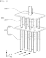
- FIG. 2 is a perspective view showing the magnetic separation unit 200 of the foreign object capturing device 1 of the present disclosure
- FIG. 3 is a plan view showing an embodiment in which the gaps I of reception pipe portion 222 of the magnetic separation unit 200 have been adjusted in the foreign object capturing device 1 of the present disclosure
- FIG. 4 is a front view showing an embodiment in which the foreign object capturing device 1 of the present disclosure is equipped with a plurality of magnetic separation units 200 disposed across an airflow direction.
- the nonmagnetic member 220 of the foreign object capturing device 1 may include a nonmagnetic plate portion 221 coupled to the captured body unit 100 and made of a nonmagnetic material, and reception pipe portion 222 coupled to the nonmagnetic plate portion 221, provided as a plurality of pipe members to correspond to the magnetic members 210 provided as a plurality of columns, and made of a nonmagnetic material.
- the nonmagnetic member 220 includes the nonmagnetic plate portion 221 and the reception pipe portion 222, magnetic foreign objects attached to the external surface of the nonmagnetic member 220 can be selected by the magnetism of the magnetic members 210 while the magnetic member 210 come out of the nonmagnetic member 220.
- reception pipe portion 222 may be provided in pipe member shapes and the magnetic members 210 may be provided in column shapes that can be inserted in the pipe member-shaped reception pipe portion 222.
- the nonmagnetic plate portion 221 is coupled to the captured body unit 100 and has the reception pipe portion 222.
- the reception pipe portion 222 are coupled to the captured body unit 100 through the nonmagnetic plate portion 221 or may be directly coupled to the captured body unit 100 without the nonmagnetic plate portion 221.
- the magnetic members 210 are inserted into or separated out of the reception pipe portion 222.
- magnetic foreign objects are attached to the external surfaces of the reception pipe portion 222 by the attraction of the magnetic members 210 attracting the magnetic foreign objects, and then when the magnetic members 210 are separated out of the reception pipe portion 222, the magnetic foreign objects attached to the external surfaces of the reception pipe portion 222 are detached and dropped.
- the reception pipe portion 222 have pipe member shapes corresponding to the columns of the magnetic members 210. Further, the magnetic members 210 may be connected to a driving member 230 to be described below to be inserted into or separated out of the reception pipe portion 222.
- the magnetic separation unit 200 of the foreign object capturing device 1 may include a driving member 230 coupled to the magnetic members 210 and providing a driving force for inserting or removing the magnetic members 210 into or out of the nonmagnetic member 220 coupled to the captured body unit 100.
- the driving member 230 may be a stretchable hydraulic or pneumatic cylinder that stretches and contracts, or an electric motor.
- the driving motor 230 configured in this way provides a driving force for moving the magnetic members 210, whereby the magnetic members 210 can be operated to be inserted into or separated out of the reception pipe portion 222.
- reception pipe portion 222 may be open at the top and closed at the bottom, and the magnetic members 210 may be connected to the driving member 230 that stretches and contracts so that the magnetic members 210 are moved down from the tops of the reception pipe portion 222 and inserted into the reception pipe portion 222 and are moved up and separated out of the reception pipe portion 222.
- reception pipe portion 222 of the foreign object capturing device 1 may be characterized to be disposed such that gaps I of adjacent reception pipe portion 222 are smaller than at least 30mm.
- Limiting the gaps I of the plurality of reception pipe portion 222 in this way is for separating magnetic foreign objects from the air flowing between the reception pipe portion 222.
- the gaps I between reception pipe portion 222 adjacent to each other is larger than 30mm, the ratio of capturing magnetic foreign objects from air remarkably decreases, so the gaps I between the reception pipe portion 222 limited.
- the nonmagnetic member 220 of the foreign object capturing device 1 may be characterized in that the gaps between the reception pipe portion 222 of a first line L1 disposed at the upstream side in the airflow direction are larger than the gaps I between the reception pipe portion 222 of a second line L2 disposed at the downstream side in the airflow direction.
- reception pipe portion 222 are disposed in this way, it is possible to more effectively remove magnetic foreign objects in the air passing through the captured body unit 100.
- the reception pipe portion 222 of the first line L1 disposed at the upstream side in the airflow direction come into contact with air earlier than the reception pipe portion 222 of the second line L2 disposed at the downstream side in the airflow direction. Since the gaps I between the reception pipe portion 222 of the first line L1 are relatively wide, magnetic foreign objects are primarily separated while problems interfering with the flow of air are minimized. Further, the reception pipe portion 222 of the second line L2 that come into contact with air later than the reception pipe portion 222 of the first line L1 remove magnetic foreign objects with a larger contact ratio with air with magnetic foreign objects primarily removed, so they remove more magnetic foreign objects.
- the reception pipe portion 222 of the second line L2 are disposed between the reception pipe portion 222 of the first line L1 across the airflow direction, so magnetic foreign objects are more effectively removed.
- nonmagnetic member 220 of the foreign object capturing device 1 may be characterized by being provided as a plurality of parts across the airflow direction.
- the magnetic member that is inserted in the nonmagnetic member 220 and the driving member 230 moving the magnetic member may also be provided as a plurality of parts.
- FIG. 5 is a side view showing an embodiment in which an anti-drag tap 222a is formed on a reception pipe 222 of the magnetic separation unit 200 of the foreign object capturing device 1 of the present disclosure.
- reception pipe 222 Since the reception pipe 222 has the anti-drag tap 222a, it is possible to prevent the problem that when the magnetic member 210 is separated out of the reception pipe 222, magnetic foreign objects attached to the external surface of the reception pipe 222 is also moved up.
- the reason that magnetic foreign objects are attached to the external surface of the reception pipe 222 is the magnetism of the magnetic member 210, so there is a problem that when the magnetic member 210 is moved, magnetic foreign objects are also moved.
- the anti-drag tap 222a Since the anti-drag tap 222a protrudes from the external surface of the reception pipe 222, the anti-drag tap 222a functions as an obstacle when magnetic foreign objects are moved on the external surface of the reception pipe 222.
- the anti-drag tap 222a may have a disc shape with a hole at the center through which the reception pipe 222 can be disposed.
- the anti-drag tap 222a of the foreign object capturing device 1 may be characterized by being perpendicularly coupled to the reception pipe 222 in a toroidal disc shape.
- the anti-drag tap 222a is perpendicularly coupled to the external surface of the reception pipe 222, magnetic foreign objects are further blocked by the anti-drag tap 222a, whereby it is possible to increase the ratio that magnetic foreign objects are detached without moving along the magnetic member 210.
- FIG. 6 is a side view showing an embodiment in which a shower unit 300 sprays fluid downward at an angle in the foreign object capturing device 1 of the present disclosure.
- the foreign object capturing device 1 may include a shower unit 300 disposed adjacent to the nonmagnetic member 220 and spraying fluid to the nonmagnetic member 220.
- shower unit 300 to be described below may also be disposed at the captured body unit 100, whereby it is possible to more effectively separate magnetic foreign objects attached to the magnetic separation unit 200.
- magnetic foreign objects can be attached to the nonmagnetic member 220 by the magnetic members 210, but may be attached by adhesive force to the external surface of the nonmagnetic member 220 even after the magnetic members 210 are separated out of the nonmagnetic member 220. Accordingly, the shower unit 300 detaches magnetic foreign objects attached as described above to the external surface of the nonmagnetic member 220.
- the shower unit 300 can spray fluid toward the nonmagnetic member 220.
- the fluid for example, may be gas such as air and may be liquid such as water.
- the shower unit 300 of the foreign object capturing device 1 may be characterized by spraying fluid downward at an angle.
- the direction in which the shower unit 300 sprays fluid is for more effectively collecting magnetic foreign objects when the under-box member 120 is provided at the lower portion of the captured body unit 100.
- the shower unit 300 sprays fluid downward at an angle to spray the fluid downward and toward the nonmagnetic member 220 such that the fluid hits against the nonmagnetic member 220.
- FIG. 7 is a configuration view showing a facility for manufacturing an electrical steel sheet.
- a facility for manufacturing an electrical steel sheet according to another embodiment of the present disclosure may include a laser chamber 2 to which an electrical steel sheet S is fed, a laser device 3 disposed in the laser chamber 2 and forming grooves in the surface of the electrical steel sheet S by radiating a laser, and the foreign object capturing device 1 linked to a hood member 2a, suctioning foreign objects scattered from the surface of the electrical steel sheet S, and receiving air containing magnetic foreign objects.
- the facility for manufacturing an electrical steel sheet S includes the laser device 3 to product a magnetic domain refinement product by forming grooves in a directional electrical steel sheet S, and includes the foreign object capturing device 1 described above that removes magnetic foreign objects of foreign objects such as spatters and fumes that are produced when grooves are formed by the laser device 3.
- the laser device 3 and the hood member 2a that transmits air containing foreign objects to the foreign object capturing device 1 are disposed in the laser chamber 2. Further, the electrical steel sheet S is fed to the laser chamber 2.
- the laser chamber 2 may have air curtains 2c at an inlet and an outlet for the electrical steel sheet S for sealing from the outside, and may have robbers 2b for supporting the electrical steel sheet S that is being moved.
- the laser device is configured to radiate a laser to from grooves on the electrical steel sheet S.
- the laser device 3 is composed of an on-off controller, a laser generator, and an optical system, and the on-off controller can turn on the generator under a normal work condition and can automatically turn off the generator in accordance with the amount of serpentine movement of the steel sheet.
Landscapes
- Engineering & Computer Science (AREA)
- Physics & Mathematics (AREA)
- Optics & Photonics (AREA)
- Plasma & Fusion (AREA)
- Mechanical Engineering (AREA)
- Chemical & Material Sciences (AREA)
- Chemical Kinetics & Catalysis (AREA)
- Cleaning In General (AREA)
- Manufacturing Of Steel Electrode Plates (AREA)
Abstract
Description
- The present disclosure relates to a foreign object capturing device and a facility for manufacturing an electrical steel sheet including the same.
- A directional electrical steel sheet having magnetic characteristics of low iron loss and high magnetic flux density is required to reduce loss of power and improve efficiency of an electrical device such as a transformer. To this end, there is a need for a process for manufacturing a magnetic domain refinement product of a directional electrical sheet, that is, a magnetic domain refinement process of reducing iron loss by forming grooves in the surface of a directional electrical steel sheet by applying a high-power continuous wave laser beam for forming grooves.
- As an example of the magnetic domain refinement process of an electrical steel sheet, there has been proposed a technology of securing an improvement ratio of iron loss after heat treatment of a directional electrical steel sheet by forming grooves through vaporization of a substance by radiation of a pulse laser, etc.
- However, such methods for permanent magnetic domain refinement are supposed to form grooves in the surface of a steel sheet, but various types of foreign objects such as particles chips, spatters, and fumes are produced on the surface of a steel sheet.
- Such foreign objects should be removed immediately with production, and if they are not removed immediately with production, there is a problem that they contaminate surrounding facilities and make a surrounding work environment worse.
- In particular, when an optical system that transmits a laser to a steel sheet is contaminated, the performance is rapidly deteriorated, so there is a problem that it is difficult to secure quality and productivity in machining of grooves.
- Accordingly, it is required to capture such foreign objects to completely remove them. Further, a capture apparatus and method should be designed in consideration of the characteristics of spatters and fumes in order to capture and remove foreign objects such as spatters and fumes.
- A spatter has a substantially spherical shape, has a diameter in the range of hundreds of nm to tens of nm, is composed of Fe, Si, C, and O, and contains magnetic foreign objects, so it is a matter to remove a spatter.
- Further, there is a defect that it is difficult to detach and collect magnetic foreign objects after the magnetic foreign objects are attached to a magnetic member.
- Accordingly, there is a need for a study of a foreign object capturing device that can improve the problems and limits described above, and a facility for manufacturing an electrical steel sheet including the foreign object capturing device.
- An objective of the present disclosure is to provide a foreign object capturing device that can remove foreign objects, and a facility for manufacturing an electrical steel sheet including the foreign object capturing device.
- Another objective of the present disclosure is to provide a foreign object capturing device that can easily detach magnetic foreign objects, which are attached by magnetism, when removing the foreign objects, and a facility for manufacturing an electrical steel sheet including the foreign object capturing device.
- A foreign object capturing device of the preset disclosure may include: a captured body unit having an inlet through which air containing magnetic foreign objects enters and an outlet through which air with magnetic foreign objects removed is discharged; and a magnetic separation unit including magnetic members, which are linked to the captured body unit and separate magnetic foreign objects from air flowing in the captured body unit using attraction, and having a nonmagnetic member surrounding the magnetic members.
- In detail, the nonmagnetic member of the foreign object capturing device according to an embodiment of the present disclosure may include a nonmagnetic plate portion coupled to the captured body unit and made of a nonmagnetic material; and a reception pipe portion coupled to the nonmagnetic plate portion, provided as a plurality of pipe members to correspond to the magnetic members provided as a plurality of columns, and made of a nonmagnetic material.
- In this configuration, the reception pipe portion of the foreign object capturing device according to an embodiment of the present disclosure may be disposed such that gaps of adjacent reception pipe portion are smaller than at least 30mm.
- Further, reception pipe portion of the foreign object capturing device according to an embodiment of the present disclosure may have an anti-drag tap formed to protrude formed circumferentially on an external surface of the reception pipe portion.
- In this configuration, the anti-drag tap of the foreign object capturing device according to an embodiment of the present disclosure may be perpendicularly coupled to the reception pipe portion in a toroidal disc shape.
- Further, the nonmagnetic member of the foreign object capturing device according to an embodiment of the present disclosure may be disposed such that gaps between reception pipe portion of a first line disposed at an upstream side in a direction of air flow are larger than gaps between reception pipe portion of a second line disposed at a downstream side in the direction of air flow.
- Further, the magnetic separation unit of the foreign object capturing device according to an embodiment of the present disclosure may include a driving member coupled to the magnetic members and providing a driving force for inserting or removing the magnetic members into or out of the nonmagnetic member coupled to the captured body unit.
- Further, the captured body unit of the foreign object capturing device according to an embodiment of the present disclosure may include: a connection pipe member that has the inlet and the outlet and to which the nonmagnetic member is coupled; and an under-box member coupled to a lower portion of the connection pipe member and receiving magnetic foreign objects dropping from the connection pipe member.
- Further, the foreign object capturing device according to an embodiment of the present disclosure may include a shower unit disposed adjacent to the nonmagnetic member and spraying fluid to the nonmagnetic member.
- In this configuration, the shower unit of the foreign object capturing device according to an embodiment may spray the fluid downward at an angle.
- A facility for manufacturing an electrical steel sheet according to another embodiment of the present disclosure may include: a laser chamber into which an electrical steel sheet is fed; a laser device disposed in the laser chamber and forming grooves in a surface of the electrical steel sheet by radiating a laser; and the foreign object capturing device of any one of claims linked to a hood member, suctioning foreign objects scattered from the surface of the electrical steel sheet, and that receiving air containing magnetic foreign objects.
- The foreign object capturing device of the preset disclosure and the facility for manufacturing an electrical steel sheet including the foreign object capturing device have an effect of being able to remove foreign objects.
- In another aspect, the foreign object capturing device of the preset disclosure and the facility for manufacturing an electrical steel sheet including the foreign object capturing device have an advantage that it is possible to easily detach magnetic foreign object attached by magnetism when removing foreign objects.
- However, various and useful advantages and effects of the present disclosure are not limited to those described above and may be more easily understood in the process of describing detailed embodiments of the present disclosure.
-
-
FIG. 1 is a configuration view showing a foreign object capturing device of the present disclosure. -
FIG. 2 is a perspective view showing a magnetic separation unit of the foreign object capturing device of the present disclosure. -
FIG. 3 is a plan view showing an embodiment in which the gaps of reception pipe portion of the magnetic separation unit have been adjusted in the foreign object capturing device of the present disclosure. -
FIG. 4 is a front view showing an embodiment in which the foreign object capturing device of the present disclosure is equipped with a plurality of magnetic separation units disposed across an airflow direction. -
FIG. 5 is a side view showing an embodiment in which an anti-drag tap is formed on a reception pipe of the magnetic separation unit of the foreign object capturing device of the present disclosure. -
FIG. 6 is a side view showing an embodiment in which a shower unit sprays fluid downward at an angle in the foreign object capturing device of the present disclosure. -
FIG. 7 is a configuration view showing a facility for manufacturing an electrical steel sheet. - Hereinafter, exemplary embodiments of the present disclosure will be described in detail with reference to the accompanying drawings. However, such embodiments of the present disclosure may be modified in various ways and the scope of the present disclosure is not limited to the embodiments to be described below. Embodiments of the present disclosure are provided to more completely explain the present disclosure to those skilled in the art. The shapes and sizes of the components in the drawings may be exaggerated for more clear explanation.
- Further, a singular expression includes a plural expression unless clearly stated otherwise in the contexts in the specification, and same or similar reference numerals indicate same or similar components throughout the specification.
- The present disclosure relates to a foreign object capturing
device 1 and a facility for manufacturing an electrical steel sheet including the foreign object capturingdevice 1, which an remove foreign objects, and in another respect, can easily detach magnetic foreign objects, which are attached by magnetism, when removing the foreign objects. - The present disclosure is described in detail with reference to drawings.
FIG. 1 is a configuration view of the foreign object capturingdevice 1 of the present disclosure. Referring to the figure, the foreign object capturingdevice 1 includes: a capturedbody unit 100 having aninlet 111 through which air containing magnetic foreign objects enters and anoutlet 112 through which air with magnetic foreign objects removed is discharged; and amagnetic separation unit 200 includingmagnetic members 210, which are linked to the capturedbody unit 100 and separate magnetic foreign objects from the air flowing in the capturedbody unit 100 using attraction, and including anonmagnetic member 220 surrounding themagnetic members 210. - As described above, the foreign object capturing
device 1 of the present disclosure can separate magnetic foreign objects by including themagnetic members 210 that separate magnetic foreign objects using magnetism in themagnetic separation unit 200. Further, magnetic foreign objects are not directly attached to themagnetic members 210 by thenonmagnetic member 220 surrounding themagnetic members 210, so it is possible to easily separate magnetic foreign objects. - The captured
body unit 100 functions as the body of the apparatus including themagnetic separation unit 200, etc., and may have theinlet 111 and theoutlet 112 to receive air containing magnetic foreign objects and discharge air with magnetic foreign objects removed through themagnetic separation unit 200 to the outside. - Further, a
shower unit 300 to be described below may also be disposed at the capturedbody unit 100, whereby it is possible to more effectively detach magnetic foreign objects attached to themagnetic separation unit 200. This configuration will be described in detail below with reference toFIG. 6 . - Further, the captured
body unit 100 may include an under-box member 120 that collects magnetic foreign objects detached by themagnetic separation unit 200, whereby it is possible to more easily handle the separated magnetic foreign objects. - That is, the foreign object capturing
device 1 according to an embodiment of the present disclosure may include aconnection pipe member 110 that has theinlet 111 and theoutlet 112 and to which thenonmagnetic member 220 is coupled, and an under-box member 120 coupled to the lower portion of theconnection pipe member 110 and receiving magnetic foreign objects dropping from theconnection pipe member 110. - In this configuration, the
connection pipe member 110 functions as a passage through which air flows. That is, since theinlet 111 and theoutlet 112 are formed at theconnection pipe member 110, air flows. - Further, since the
connection pipe member 110 is equipped with themagnetic separation unit 200, magnetic foreign objects are separated and removed from the air passing through theconnection pipe member 110. - Further, the
connection pipe member 110 may be equipped also theshower unit 300, whereby it is possible to more effectively detach magnetic foreign objects attached to themagnetic separation unit 200. - When magnetic foreign objects separated by the
magnetic separation unit 200 are detached and dropped from themagnetic separation unit 200, the under-box member 120 collects the magnetic foreign objects. - To this end, the under-
box member 120 may be coupled to the lower portion of theconnection pipe member 110 equipped with themagnetic separation unit 200. Further, the under-box member 120 may communicate with the lower portion of theconnection pipe member 110 to collect dropping magnetic foreign objects. - The
magnetic separation unit 200 serves to separate and remove magnetic foreign objects from air containing the magnetic foreign objects. To this end, themagnetic separation unit 200 may include themagnetic members 210 linked to the capturedbody unit 100 and separating magnetic foreign objects using attraction, and thenonmagnetic member 220 surrounding themagnetic members 210 to prevent magnetic foreign objects from being directly attached to themagnetic members 210. - Magnetic foreign objects separated by the
magnetic members 210 and attached to the external surface of thenonmagnetic member 220 by the magnetism of themagnetic members 210 can be detached while themagnetic members 210 come out of thenonmagnetic member 220, which will be described in detail below with reference toFIGS. 2 to 4 . -
FIG. 2 is a perspective view showing themagnetic separation unit 200 of the foreignobject capturing device 1 of the present disclosure,FIG. 3 is a plan view showing an embodiment in which the gaps I ofreception pipe portion 222 of themagnetic separation unit 200 have been adjusted in the foreignobject capturing device 1 of the present disclosure, andFIG. 4 is a front view showing an embodiment in which the foreignobject capturing device 1 of the present disclosure is equipped with a plurality ofmagnetic separation units 200 disposed across an airflow direction. - Referring to the figures, the
nonmagnetic member 220 of the foreignobject capturing device 1 according to an embodiment of the present disclosure may include anonmagnetic plate portion 221 coupled to the capturedbody unit 100 and made of a nonmagnetic material, andreception pipe portion 222 coupled to thenonmagnetic plate portion 221, provided as a plurality of pipe members to correspond to themagnetic members 210 provided as a plurality of columns, and made of a nonmagnetic material. - As described above, since the
nonmagnetic member 220 includes thenonmagnetic plate portion 221 and thereception pipe portion 222, magnetic foreign objects attached to the external surface of thenonmagnetic member 220 can be selected by the magnetism of themagnetic members 210 while themagnetic member 210 come out of thenonmagnetic member 220. - In other words, the
reception pipe portion 222 may be provided in pipe member shapes and themagnetic members 210 may be provided in column shapes that can be inserted in the pipe member-shapedreception pipe portion 222. - The
nonmagnetic plate portion 221 is coupled to the capturedbody unit 100 and has thereception pipe portion 222. - The
reception pipe portion 222 are coupled to the capturedbody unit 100 through thenonmagnetic plate portion 221 or may be directly coupled to the capturedbody unit 100 without thenonmagnetic plate portion 221. - The
magnetic members 210 are inserted into or separated out of thereception pipe portion 222. When themagnetic members 210 are inserted in thereception pipe portion 222, magnetic foreign objects are attached to the external surfaces of thereception pipe portion 222 by the attraction of themagnetic members 210 attracting the magnetic foreign objects, and then when themagnetic members 210 are separated out of thereception pipe portion 222, the magnetic foreign objects attached to the external surfaces of thereception pipe portion 222 are detached and dropped. - To this end, the
reception pipe portion 222 have pipe member shapes corresponding to the columns of themagnetic members 210. Further, themagnetic members 210 may be connected to a drivingmember 230 to be described below to be inserted into or separated out of thereception pipe portion 222. - That is, the
magnetic separation unit 200 of the foreignobject capturing device 1 according to an embodiment of the present disclosure may include a drivingmember 230 coupled to themagnetic members 210 and providing a driving force for inserting or removing themagnetic members 210 into or out of thenonmagnetic member 220 coupled to the capturedbody unit 100. - In this configuration, the driving
member 230 may be a stretchable hydraulic or pneumatic cylinder that stretches and contracts, or an electric motor. - The driving
motor 230 configured in this way provides a driving force for moving themagnetic members 210, whereby themagnetic members 210 can be operated to be inserted into or separated out of thereception pipe portion 222. - For example,
reception pipe portion 222 may be open at the top and closed at the bottom, and themagnetic members 210 may be connected to the drivingmember 230 that stretches and contracts so that themagnetic members 210 are moved down from the tops of thereception pipe portion 222 and inserted into thereception pipe portion 222 and are moved up and separated out of thereception pipe portion 222. - Further, the
reception pipe portion 222 of the foreignobject capturing device 1 according to an embodiment of the present disclosure may be characterized to be disposed such that gaps I of adjacentreception pipe portion 222 are smaller than at least 30mm. - Limiting the gaps I of the plurality of
reception pipe portion 222 in this way is for separating magnetic foreign objects from the air flowing between thereception pipe portion 222. - That is, if the gaps I between
reception pipe portion 222 adjacent to each other is larger than 30mm, the ratio of capturing magnetic foreign objects from air remarkably decreases, so the gaps I between thereception pipe portion 222 limited. - Further, the
nonmagnetic member 220 of the foreignobject capturing device 1 according to an embodiment of the present disclosure may be characterized in that the gaps between thereception pipe portion 222 of a first line L1 disposed at the upstream side in the airflow direction are larger than the gaps I between thereception pipe portion 222 of a second line L2 disposed at the downstream side in the airflow direction. - Since the
reception pipe portion 222 are disposed in this way, it is possible to more effectively remove magnetic foreign objects in the air passing through the capturedbody unit 100. - That is, the
reception pipe portion 222 of the first line L1 disposed at the upstream side in the airflow direction come into contact with air earlier than thereception pipe portion 222 of the second line L2 disposed at the downstream side in the airflow direction. Since the gaps I between thereception pipe portion 222 of the first line L1 are relatively wide, magnetic foreign objects are primarily separated while problems interfering with the flow of air are minimized. Further, thereception pipe portion 222 of the second line L2 that come into contact with air later than thereception pipe portion 222 of the first line L1 remove magnetic foreign objects with a larger contact ratio with air with magnetic foreign objects primarily removed, so they remove more magnetic foreign objects. - Further, according to this disposition, the
reception pipe portion 222 of the second line L2 are disposed between thereception pipe portion 222 of the first line L1 across the airflow direction, so magnetic foreign objects are more effectively removed. - Further, the
nonmagnetic member 220 of the foreignobject capturing device 1 according to an embodiment of the present disclosure may be characterized by being provided as a plurality of parts across the airflow direction. - Accordingly, the magnetic member that is inserted in the
nonmagnetic member 220 and the drivingmember 230 moving the magnetic member may also be provided as a plurality of parts. - Accordingly, it is possible to remove magnetic foreign objects only at a portion across the airflow direction, so it is possible to adjust the degree of capturing magnetic foreign objects.
-
FIG. 5 is a side view showing an embodiment in which ananti-drag tap 222a is formed on areception pipe 222 of themagnetic separation unit 200 of the foreignobject capturing device 1 of the present disclosure. - Since the
reception pipe 222 has theanti-drag tap 222a, it is possible to prevent the problem that when themagnetic member 210 is separated out of thereception pipe 222, magnetic foreign objects attached to the external surface of thereception pipe 222 is also moved up. - In other words, the reason that magnetic foreign objects are attached to the external surface of the
reception pipe 222 is the magnetism of themagnetic member 210, so there is a problem that when themagnetic member 210 is moved, magnetic foreign objects are also moved. - Since the
anti-drag tap 222a protrudes from the external surface of thereception pipe 222, theanti-drag tap 222a functions as an obstacle when magnetic foreign objects are moved on the external surface of thereception pipe 222. - Accordingly, magnetic foreign objects are blocked and separated by the
anti-drag tap 222a without moving along themagnetic member 210. - In more detail, the
anti-drag tap 222a may have a disc shape with a hole at the center through which thereception pipe 222 can be disposed. - That is, the
anti-drag tap 222a of the foreignobject capturing device 1 according to an embodiment of the present disclosure may be characterized by being perpendicularly coupled to thereception pipe 222 in a toroidal disc shape. - Since the
anti-drag tap 222a is perpendicularly coupled to the external surface of thereception pipe 222, magnetic foreign objects are further blocked by theanti-drag tap 222a, whereby it is possible to increase the ratio that magnetic foreign objects are detached without moving along themagnetic member 210. -
FIG. 6 is a side view showing an embodiment in which ashower unit 300 sprays fluid downward at an angle in the foreignobject capturing device 1 of the present disclosure. Referring to the figure, the foreignobject capturing device 1 according to an embodiment may include ashower unit 300 disposed adjacent to thenonmagnetic member 220 and spraying fluid to thenonmagnetic member 220. - That is, the
shower unit 300 to be described below may also be disposed at the capturedbody unit 100, whereby it is possible to more effectively separate magnetic foreign objects attached to themagnetic separation unit 200. - In other words, magnetic foreign objects can be attached to the
nonmagnetic member 220 by themagnetic members 210, but may be attached by adhesive force to the external surface of thenonmagnetic member 220 even after themagnetic members 210 are separated out of thenonmagnetic member 220. Accordingly, theshower unit 300 detaches magnetic foreign objects attached as described above to the external surface of thenonmagnetic member 220. - To this end, the
shower unit 300 can spray fluid toward thenonmagnetic member 220. The fluid, for example, may be gas such as air and may be liquid such as water. - In this configuration, the
shower unit 300 of the foreignobject capturing device 1 according to an embodiment of the present disclosure may be characterized by spraying fluid downward at an angle. - As described above, the direction in which the
shower unit 300 sprays fluid is for more effectively collecting magnetic foreign objects when the under-box member 120 is provided at the lower portion of the capturedbody unit 100. - That is, the
shower unit 300 sprays fluid downward at an angle to spray the fluid downward and toward thenonmagnetic member 220 such that the fluid hits against thenonmagnetic member 220. -
FIG. 7 is a configuration view showing a facility for manufacturing an electrical steel sheet. Referring to the figure, a facility for manufacturing an electrical steel sheet according to another embodiment of the present disclosure may include a laser chamber 2 to which an electrical steel sheet S is fed, alaser device 3 disposed in the laser chamber 2 and forming grooves in the surface of the electrical steel sheet S by radiating a laser, and the foreignobject capturing device 1 linked to ahood member 2a, suctioning foreign objects scattered from the surface of the electrical steel sheet S, and receiving air containing magnetic foreign objects. - As described above, the facility for manufacturing an electrical steel sheet S includes the
laser device 3 to product a magnetic domain refinement product by forming grooves in a directional electrical steel sheet S, and includes the foreignobject capturing device 1 described above that removes magnetic foreign objects of foreign objects such as spatters and fumes that are produced when grooves are formed by thelaser device 3. - In this configuration, the
laser device 3 and thehood member 2a that transmits air containing foreign objects to the foreignobject capturing device 1 are disposed in the laser chamber 2. Further, the electrical steel sheet S is fed to the laser chamber 2. - The laser chamber 2 may have
air curtains 2c at an inlet and an outlet for the electrical steel sheet S for sealing from the outside, and may haverobbers 2b for supporting the electrical steel sheet S that is being moved. - The laser device is configured to radiate a laser to from grooves on the electrical steel sheet S. For example, the
laser device 3 is composed of an on-off controller, a laser generator, and an optical system, and the on-off controller can turn on the generator under a normal work condition and can automatically turn off the generator in accordance with the amount of serpentine movement of the steel sheet. - Although embodiments of the present disclosure were described above, it would be apparent to those skilled in the art that the scope of the present disclosure is not limited thereto and the present disclosure may be changed and modified in various ways without departing from the spirit of the present disclosure described in claims.
Claims (11)
- A foreign object capturing device comprising:a captured body unit having an inlet through which air containing magnetic foreign objects enters and an outlet through which air with magnetic foreign objects removed is discharged; anda magnetic separation unit including magnetic members, which are linked to the captured body unit and separate magnetic foreign objects from air flowing in the captured body unit using attraction, and having a nonmagnetic member surrounding the magnetic members.
- The foreign object capturing device of claim 1, wherein the nonmagnetic member includes:a nonmagnetic plate portion coupled to the captured body unit and made of a nonmagnetic material; anda reception pipe portion coupled to the nonmagnetic plate portion, provided as a plurality of pipe members to correspond to the magnetic members provided as a plurality of columns, and made of a nonmagnetic material.
- The foreign object capturing device of claim 2, wherein the reception pipe portion are disposed such that gaps of adjacent reception pipe portion are smaller than at least 30mm.
- The foreign object capturing device of claim 2, wherein the reception pipe portion have an anti-drag tap formed to protrude circumferentially on an external surface of the reception pipe portion.
- The foreign object capturing device of claim 4, wherein the anti-drag tap is perpendicularly coupled to the reception pipe portion in a toroidal disc shape.
- The foreign object capturing device of claim 2, wherein the nonmagnetic member is disposed such that gaps between reception pipe portion of a first line disposed at an upstream side in a direction of air flow are larger than gaps between reception pipe portion of a second line disposed at a downstream side in the direction of air flow.
- The foreign object capturing device of claim 1, wherein the magnetic separation unit includes a driving member coupled to the magnetic members and providing a driving force for inserting or removing the magnetic members into or out of the nonmagnetic member coupled to the captured body unit.
- The foreign object capturing device of claim 1, wherein the captured body unit includes:a connection pipe member that has the inlet and the outlet and to which the nonmagnetic member is coupled; andan under-box member coupled to a lower portion of the connection pipe member and receiving magnetic foreign objects dropping from the connection pipe member.
- The foreign object capturing device of claim 1, comprising a shower unit disposed adjacent to the nonmagnetic member and spraying fluid to the nonmagnetic member.
- The foreign object capturing device of claim 9, wherein the shower unit sprays the fluid downward at an angle.
- A facility for manufacturing an electrical steel sheet, the facility comprising:a laser chamber into which an electrical steel sheet is fed;a laser device disposed in the laser chamber and forming grooves in a surface of the electrical steel sheet by radiating a laser; andthe foreign object capturing device of any one of claims 1 to 10 that is linked to a hood member, suctioning foreign objects scattered from the surface of the electrical steel sheet, and that receives air containing magnetic foreign objects.
Applications Claiming Priority (2)
| Application Number | Priority Date | Filing Date | Title |
|---|---|---|---|
| KR1020190147864A KR102348569B1 (en) | 2019-11-18 | 2019-11-18 | Alien substance capturing apparatus and electrical steel sheet manufacturing facility having thereof |
| PCT/KR2020/016149 WO2021101206A1 (en) | 2019-11-18 | 2020-11-17 | Foreign substance capturing apparatus and electrical steel sheet manufacturing facility comprising same |
Publications (2)
| Publication Number | Publication Date |
|---|---|
| EP4063059A1 true EP4063059A1 (en) | 2022-09-28 |
| EP4063059A4 EP4063059A4 (en) | 2023-01-11 |
Family
ID=75980882
Family Applications (1)
| Application Number | Title | Priority Date | Filing Date |
|---|---|---|---|
| EP20888835.4A Pending EP4063059A4 (en) | 2019-11-18 | 2020-11-17 | Foreign substance capturing apparatus and electrical steel sheet manufacturing facility comprising same |
Country Status (6)
| Country | Link |
|---|---|
| US (1) | US12239931B2 (en) |
| EP (1) | EP4063059A4 (en) |
| JP (1) | JP7461474B2 (en) |
| KR (1) | KR102348569B1 (en) |
| CN (1) | CN114728375B (en) |
| WO (1) | WO2021101206A1 (en) |
Family Cites Families (18)
| Publication number | Priority date | Publication date | Assignee | Title |
|---|---|---|---|---|
| KR0135456Y1 (en) | 1994-09-01 | 1999-03-20 | 김무수 | Rotary type filter device |
| NL1001427C2 (en) * | 1995-10-16 | 1997-04-17 | Paulus Wolfs | Device for removing magnetizable parts. |
| KR200259782Y1 (en) * | 2001-08-22 | 2002-01-09 | 이건국 | The Structure of CO2 Welding Fume Suction Torch with in Flexible Suction Pipe and Fume Collector use of magnet |
| KR20070098967A (en) | 2007-08-29 | 2007-10-08 | 김원준 | Secondary coolant tank for microchip removal |
| JP5799580B2 (en) | 2011-05-23 | 2015-10-28 | 日立化成株式会社 | Magnetic separator, method for removing magnetic impurities, and method for manufacturing lithium ion secondary battery |
| KR101397277B1 (en) * | 2012-05-16 | 2014-05-21 | 삼성전기주식회사 | Apparatus for removing dust and method for removing dust by using the same |
| US8636907B1 (en) | 2013-05-09 | 2014-01-28 | Amt International, Inc. | Sealed magnetic filter for hazardous operations and easy clean service |
| KR102362753B1 (en) * | 2015-07-24 | 2022-02-11 | 주식회사 포스코 | Dust collector and appratus for refining magnetic domains in grain-oriented electrical steel sheet with the same |
| US9352331B1 (en) | 2015-09-26 | 2016-05-31 | Allnew Chemical Technology Company | Filters for paramagnetic and diamagnetic substances |
| KR101739868B1 (en) | 2016-01-22 | 2017-05-25 | 주식회사 포스코 | Method and apparatus for refining magnetic domains grain-oriented electrical steel |
| KR101739870B1 (en) * | 2016-01-22 | 2017-05-25 | 주식회사 포스코 | Method and apparatus for refining magnetic domains grain-oriented electrical steel |
| JP6663254B2 (en) | 2016-03-08 | 2020-03-11 | 富士電機株式会社 | Wastewater treatment apparatus and wastewater treatment method |
| NL2017443B1 (en) | 2016-09-09 | 2018-03-15 | Mhd Tech B V | Device and method for magnetic separation |
| KR102501548B1 (en) | 2016-09-23 | 2023-02-20 | 한국식품연구원 | A composition for improving, preventing and treating of fatty liver diseases comprising leek extract |
| GB201616947D0 (en) | 2016-10-05 | 2016-11-23 | Romar International Limited | Apparatus and method for removing magnetic particles from liquids and slurries |
| KR101988792B1 (en) | 2018-03-05 | 2019-09-30 | 건국대학교 산학협력단 | Dust collecting device using magnetic force |
| KR101906495B1 (en) | 2018-03-21 | 2018-10-10 | (주)청도이엔피 | Apparatus of Coarsening Particulate Matter and Method for Removing Particulate Matter Using Thereof |
| CN110201792B (en) | 2019-06-15 | 2024-06-07 | 李泽 | Fluid deironing method and device |
-
2019
- 2019-11-18 KR KR1020190147864A patent/KR102348569B1/en active Active
-
2020
- 2020-11-17 WO PCT/KR2020/016149 patent/WO2021101206A1/en not_active Ceased
- 2020-11-17 CN CN202080079947.XA patent/CN114728375B/en active Active
- 2020-11-17 US US17/777,471 patent/US12239931B2/en active Active
- 2020-11-17 EP EP20888835.4A patent/EP4063059A4/en active Pending
- 2020-11-17 JP JP2022528716A patent/JP7461474B2/en active Active
Also Published As
| Publication number | Publication date |
|---|---|
| KR20210060165A (en) | 2021-05-26 |
| WO2021101206A1 (en) | 2021-05-27 |
| CN114728375A (en) | 2022-07-08 |
| JP7461474B2 (en) | 2024-04-03 |
| US12239931B2 (en) | 2025-03-04 |
| EP4063059A4 (en) | 2023-01-11 |
| JP2023501833A (en) | 2023-01-19 |
| CN114728375B (en) | 2023-11-24 |
| US20230027665A1 (en) | 2023-01-26 |
| KR102348569B1 (en) | 2022-01-06 |
Similar Documents
| Publication | Publication Date | Title |
|---|---|---|
| EP3509753B1 (en) | Apparatus and method for magnetic separation | |
| WO2014182424A1 (en) | Sealed magnetic filter for hazardous operations and easy clean-up service | |
| FI74412C (en) | Device for purifying a particle-loaded liquid. | |
| JP2005021835A (en) | Magnetic particle recovery apparatus | |
| US12239931B2 (en) | Foreign substance capture apparatus and facility for manufacturing electrical steel sheet including same | |
| EP2308578A1 (en) | Filtering device | |
| US12138709B2 (en) | Foreign substance collecting apparatus and electrical steel sheet manufacturing facility including same | |
| JP4898182B2 (en) | Filtration device | |
| JP2007281203A (en) | Joining method and joining apparatus for joining two workpieces | |
| JP2011212601A (en) | Magnetic particle removing apparatus and cleaning system for fluid to be treated | |
| JP7215853B2 (en) | METAL REMOVAL APPARATUS, SUBSTRATE PROCESSING APPARATUS, AND SUBSTRATE PROCESSING METHOD | |
| DE202017101871U1 (en) | Body workstation for machining vehicle bodies | |
| JP2008304424A (en) | Magnetic particle inspection liquid ejection device | |
| WO1993008919A1 (en) | Magnetic disc separator | |
| JPH11342349A (en) | Magnetic separation device | |
| CN222818064U (en) | Processing equipment for surface treatment of parts | |
| CN210559666U (en) | Alloy scale remover | |
| RU2372135C1 (en) | Device for extraction of magnetic particles from liquid medium | |
| JPH10286740A (en) | Coolant purifier of machine tool | |
| RU2079374C1 (en) | Electromagnetic separator | |
| JPS60232219A (en) | Filter apparatus | |
| KR20010001094A (en) | Aaaaa | |
| JPS6026582B2 (en) | High gradient magnetic separator |
Legal Events
| Date | Code | Title | Description |
|---|---|---|---|
| STAA | Information on the status of an ep patent application or granted ep patent |
Free format text: STATUS: THE INTERNATIONAL PUBLICATION HAS BEEN MADE |
|
| PUAI | Public reference made under article 153(3) epc to a published international application that has entered the european phase |
Free format text: ORIGINAL CODE: 0009012 |
|
| STAA | Information on the status of an ep patent application or granted ep patent |
Free format text: STATUS: REQUEST FOR EXAMINATION WAS MADE |
|
| 17P | Request for examination filed |
Effective date: 20220617 |
|
| AK | Designated contracting states |
Kind code of ref document: A1 Designated state(s): AL AT BE BG CH CY CZ DE DK EE ES FI FR GB GR HR HU IE IS IT LI LT LU LV MC MK MT NL NO PL PT RO RS SE SI SK SM TR |
|
| A4 | Supplementary search report drawn up and despatched |
Effective date: 20221214 |
|
| RIC1 | Information provided on ipc code assigned before grant |
Ipc: B08B 15/04 20060101ALI20221208BHEP Ipc: B23K 26/364 20140101ALI20221208BHEP Ipc: B23K 26/16 20060101AFI20221208BHEP |
|
| DAV | Request for validation of the european patent (deleted) | ||
| DAX | Request for extension of the european patent (deleted) | ||
| STAA | Information on the status of an ep patent application or granted ep patent |
Free format text: STATUS: EXAMINATION IS IN PROGRESS |
|
| 17Q | First examination report despatched |
Effective date: 20250408 |